table of contents - faculty.kutztown.edufaculty.kutztown.edu/tan/csc354/datafiles/new/354/browser...
TRANSCRIPT

High Level DesignVersion 2.6
Browser Team
Mamadou Diallo
Tamara Jennings
Alexander Posipanko
Jordy Then
David Vera
Perrillen Zuniga
CSC 354
Dr. Tan

High Level Design December 5, 2018
Table of ContentsTable of Contents….….….….….….….….….….….….….….….….….….….….….….….….….….….….….….….….….….….….…. i
REVISION HISTORY….….….….….….….….….….….….….….….….….….….….….….….….….….….….….….….….….….….….. ii
1.0 INTRODUCTION….….….….….….….….….….….….….….….….….….….….….….….….….….….….….….….….….….….…. 1
1.1 Purpose of Document….….….….….….….….….….….….….….….….….….….….….….….….….….….….….….….….. 1
1.2 What are System Sequence Diagrams….….….….….….….….….….….….….….….….….….….….….….….….….… 1
1.3 Explanatory Material: Acronyms & Meanings….….….….….….….….….….….….….….….….….….….….…...…. 1
2.0 SYSTEM ARCHITECTURE DESIGN….….….….….….….….….….….….….….….….….….….….….….….….….….….….…. 2
3.0 UML NOTATION….….….….….….….….….….….….….….….….….….….….….….….….….….….….….….….….….….……. 3
4.0 SYSTEM SEQUENCE DIAGRAMS….….….….….….….….….….….….….….….….….….….….….….….….….….….….….. 5
4.1 CNO Assigns a Task to a Patient….….….….….….….….….….….….….….….….….….….….….….….….….….….…. 5
4.2 CNO Creates a Task….….….….….….….….….….….….….….….….….….….….….….….….….….….….….….….….….. 6
4.3 Director Creates a Staff Portfolio….….….….….….….….….….….….….….….….….….….….….….….….….….….. 7
4.4 Director Uploads Center Schedule….….….….….….….….….….….….….….….….….….….….….….….….….…… 8
4.5 Director Submits Feedback….….….….….….….….….….….….….….….….….….….….….….….….….….….….…… 9

High Level Design December 5, 2018
REVISION HISTORYThe up-to-date revision history is listed in Table 1. As changes to this document are made, the table will be edited to reflect them.
Version Date Description Editor
1.0 11/12/2018 Created Document Tamara Jennings
1.1 11/13/2018 Wrote:
Section 1.0 Introduction
Section 1.1 Purpose of Document
Section 1.2 What are System Sequence Diagrams
Mamadou Diallo
Wrote:
Section 3.0 UML Notation
Edited:
Section 1.4 Acronyms & References
Jordy Then
1.2 11/14/2018 Wrote:
Section 4.1 Assign a Task
Section 4.2 Create a Task
Section 4.3 Create Staff Portfolio
Section 4.4 Upload new Schedule
Section 4.5 Submit Feedback
Alexander Posipanko
1.3 11/15/2018 Edited:
Section 1.0 Introduction
Section 1.1 Purpose of Document
Section 1.2 What are System Sequence Diagrams
Section 1.3 Explanatory Material
Perrillen Zuniga

High Level Design December 5, 2018
Edited:
Section 4.1 Assign a Task
Section 4.2 Create a Task
Section 4.3 Create Staff Portfolio
Section 4.4 Upload new Schedule
Section 4.5 Submit Feedback
Alexander Posipanko
Edited:
Section 4.0 System Sequence Diagram
Section 4.1 Assign a Task
Section 4.2 Create a Task
Section 4.3 Create Staff Portfolio
Section 4.4 Upload new Schedule
Section 4.5 Submit Feedback
David Vera
Wrote:
Section 2.0 System Architecture Design
Tamara Jennings
1.4 11/16/2018 Edited:
Page Numbers
Table of Contents
Section 1.1 Purpose of Document
Section 1.2 What are System Sequence Diagrams
Tamara Jennings
2.0 11/28/2018 Edited:
Section 1.0 Introduction
Section 1.2 What are System Sequence Diagrams
Section 1.4 Acronyms & Meanings
Mamadou Diallo
2.1 11/29/2018 Edited: Tamara Jennings

High Level Design December 5, 2018
Section 1.1 Purpose of Document
Section 1.2 What are System Sequence Diagrams
Edited:
Section 3.0 UML Notations
Jordy Then
2.2 11/30/2018 Edited:
Section 4.0 System Sequence Diagrams
Section 4.1 CNO Assigns Task to a Patient
David Vera
2.3 12/3/2018 Edited:
Section 4.2 CNO Creates a Task
Section 4.3 Director Creates a Staff Portfolio
Section 4.4 Director Uploads New Schedule
Section 4.5 Director Submits Feedback
David Vera
Edited:
1.0 Introduction
1.1 Purpose of Document
1.2 What are System Sequence Diagrams
2.0 System Architecture Design
3.0 UML Notation
4.3 Director Creates a Staff Portfolio
Perrillen Zuniga
2.4 12/4/2018 Edited:
4.1 CNO Assigns a task to a patient
4.2 CNO Creates a Task
4.3 Director Creates a Staff Portfolio
Alexander Posipanko
Edited:
2.0 System Architecture Design
David Vera
Edited: Tamara Jennings

High Level Design December 5, 2018
4.4 Director Uploads Center Schedule
2.5 12/6/2018 Edited:
3.0: UML Notation
Table of Contents
Perrillen Zuniga
Edited:
4.4 Director Uploads Center Schedule
4.5 Director Submits Feedback
Alexander Posipanko
Edited:
3.0: UML Notation
Jordy Then
2.6 12/7/2018 Edited:
1.3 Acronyms & Meanings
2.0 System Architecture Design
Tamara Jennings
Table 1: Revision History

High Level Design December 5, 2018
1.0 INTRODUCTIONHigh-level design (HLD) provides a view of the Long Term Care Task Management System (LTC-TMS) at an abstract level. It shows how the major pieces of the finished system will fit together and interact with each other. A high-level design should also specify assumptions about the environment in which the finished system will run. For example, it should describe the hardware and software the browser team will be using to develop the web application, and the hardware that will eventually run the program.
1.1 Purpose of Document LTC-TMS is a task management system intended for use in long-term care facilities to assist Directors and chief nursing officers (CNO) with maintaining patients’ health and personal data as well as staff administration. It will allow certified nurse assistants (CNA) to maintain patients’ health data. The system will also allow patients and approved family members to view their health and personal data. The purpose of this document is to describe the structure and behavior of the system using diagrams, specifically the system architecture design diagram detailed in Section 2.0 and the system sequence diagrams provided in Section 4.0. It will detail the architectural design of the system, that is, the main components of the system and their relationships with each other.
1.2 What are System Sequence DiagramsA system sequence diagram (SSD) is, as the name suggests, a type of sequence diagram developed using the Unified Modeling Language (UML). These diagrams depict scenarios in which the user triggers an event on the system and the system responds to that event. SSDs are based on the functional requirements outlined by the client in the Software Requirements Specification document.
1.3 Explanatory Material: Acronyms & MeaningsThe acronyms and terms listed in Table 2 are used throughout this document.
Acronym Full Name
CNA Certified Nurse Assistant: a staff member that works directly with patients
CNO Chief Nursing Officer: an administrative staff member in charge of CNAs
HLD High-level design
SSD System Sequence Diagram
UML Unified Modeling Language
LTC-TMS Long Term Care Task Management System
Raspberry Pi A computer used to take in data gathered by sensors and send it to the database
Micro:bit Computing system used to collect data from the sensors to be sent to the database
Table 2: Acronyms & Meanings

High Level Design December 5, 2018
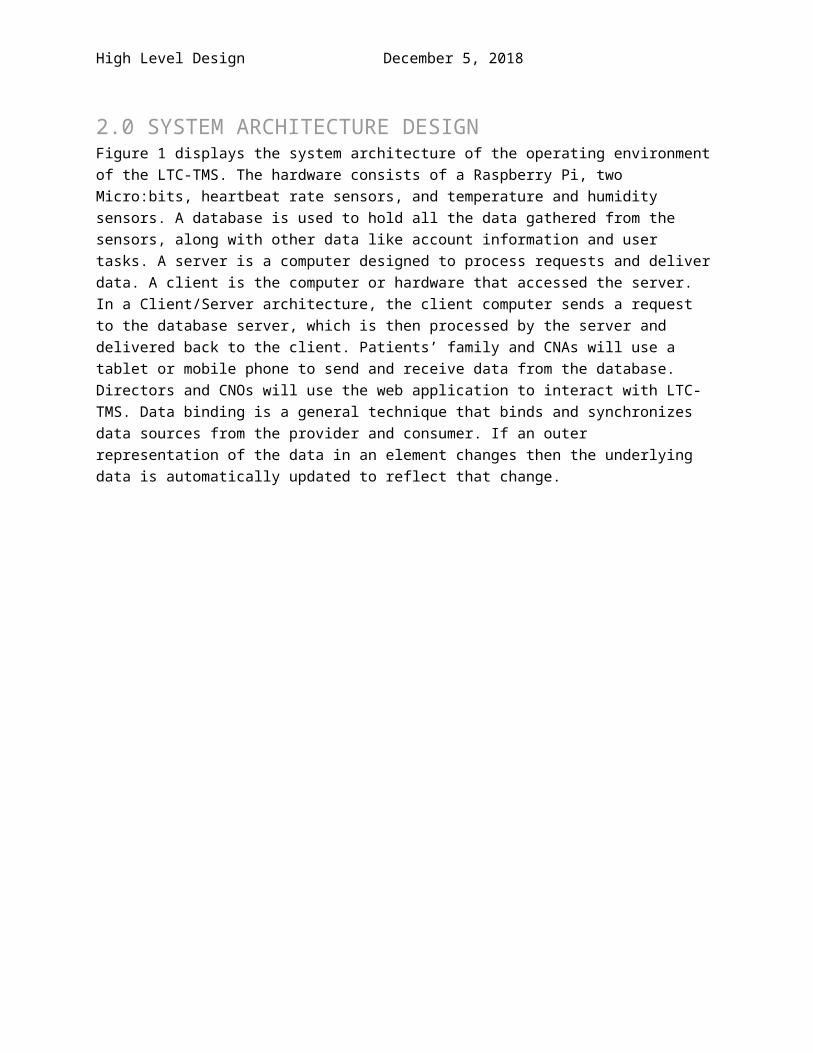
2.0 SYSTEM ARCHITECTURE DESIGNFigure 1 displays the system architecture of the operating environment of the LTC-TMS. The hardware consists of a Raspberry Pi, two Micro:bits, heartbeat rate sensors, and temperature and humidity sensors. A database is used to hold all the data gathered from the sensors, along with other data like account information and user tasks. A server is a computer designed to process requests and deliver data. A client is the computer or hardware that accessed the server. In a Client/Server architecture, the client computer sends a request to the database server, which is then processed by the server and delivered back to the client. Patients’ family and CNAs will use a tablet or mobile phone to send and receive data from the database. Directors and CNOs will use the web application to interact with LTC-TMS. Data binding is a general technique that binds and synchronizes data sources from the provider and consumer. If an outer representation of the data in an element changes then the underlying data is automatically updated to reflect that change.
Figure 1: System Architecture Design

High Level Design December 5, 2018
3.0 UML NOTATIONThis section explains the symbols and notations for the System Sequence Diagrams in Section 4.0. Table 3 demonstrates symbols, along with a description of the symbol to help guide readers to understand the UML notations of the SSD.
Symbol Description
The stick figure represents an actor/user that will be interacting with the system. The symbol will have a name beneath it that identifies their role in the scenario of the SSD. The symbol is located on the top left position of the diagram.
This symbol indicates a rectangular box with the word “:system” inside. The symbol represents the entire LTC-TMS system as a black box and is adjacent to the stick figure.
This symbol indicates a vertical dotted line that extrudes below the actor and the system. The symbol designates the object’s lifeline. It emphasizes chronological order of the sequence of messages being passed between the actor and system in the scenario.
A solid-line with an arrow head pointing to the right represents an input message from the actor to the system. The symbol includes a message above the arrow that specifies a requests from the actor. The message may take parameters, depending on the message and action.
A dotted-line with an arrow head pointing to the left represents the returned value from the system to the actor. The symbol includes a response message or action below the dotted line that shows what the system have processed regarding the requests from the actor.
High Level Design December 5, 2018
Symbols DescriptionThis symbol indicates a box with a fold on the top right corner. The symbol represents a note. One of the purpose of this symbol is to elaborate on the returned value. It is used as an extension of a message that may not fit in the diagram. Also, another purpose of this symbol is to indicate assumptions and/or constraints of the scenario.This symbol indicates a box that surrounds an actor and system interactions with a loop condition on the top left of the box. This is the traditional notation to represent looping in the SSD. The box surrounds a series of input messages and system responses that specifies what section is going to be iterated until the condition is met.
This symbol indicates a solid arrow to the right with a condition statement and system response above the arrow, along with a parameter statement below the arrow which is the user input. The symbol is an alternate notation to represent looping in the SSD. The asterisk and square brackets will hold a condition for the parameter. The message on top of the line is the return value of the loop statement and the message on bottom of the line is the input statement for the server. As long as the condition is true, the statement will loop.This symbol indicates 2 boxes that surrounds an actor and system interactions with an if statement condition on the top left of the first box and an else statement on the top left of the second box. The symbol represents an if, else statement in the SSD. When the condition of the if statement is true, the system will provide a response to the actor’s request. When the condition of the if statement is false, the system will provide an error message to the actor.
Table 3: UML Notation

High Level Design December 5, 2018
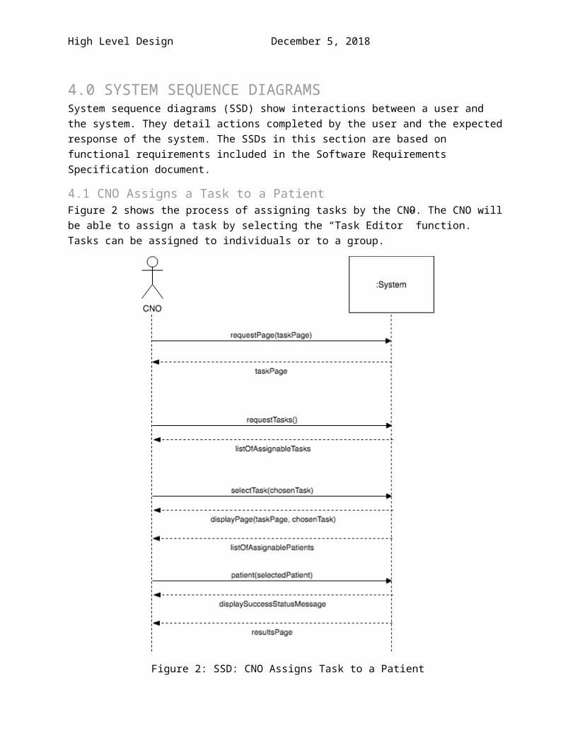
4.0 SYSTEM SEQUENCE DIAGRAMSSystem sequence diagrams (SSD) show interactions between a user and the system. They detail actions completed by the user and the expected response of the system. The SSDs in this section are based on functional requirements included in the Software Requirements Specification document.
4.1 CNO Assigns a Task to a PatientFigure 2 shows the process of assigning tasks by the CNO. The CNO will be able to assign a task by selecting the “Task Editor” function. Tasks can be assigned to individuals or to a group.
Figure 2: SSD: CNO Assigns Task to a Patient

High Level Design December 5, 2018
4.2 CNO Creates a TaskFigure 3 shows the sequence for creating a task. Task creation can be done by both the Director and CNO. Once a task is created, it will be published to a library of tasks.
Figure 3: SSD: CNO Creates a Task

High Level Design December 5, 2018
4.3 Director Creates a Staff PortfolioFigure 4 shows the steps that will be taken to create staff portfolios. The Director will be allowed to create staff portfolios for each staff member. After the Director creates a new portfolio, they will be required to input information about the staff. This information will then be displayed as part of the portfolio and then the portfolio will be uploaded to the LTC-TMS database.
Figure 4: SSD: Director Creates a Staff Portfolio

High Level Design December 5, 2018
4.4 Director Uploads Center ScheduleThe director is given the ability to upload schedules. A center schedule will contain information about events at the center and can be viewed by all staff members. As shown in Figure 5, an “Upload New Schedule” button will be displayed for the director to press to add a new center schedule.
Figure 5: SSD: Director Uploads a Center Schedule
High Level Design December 5, 2018
4.5 Director Submits FeedbackDirector will be able to submit feedback on the system. The “Add Feedback” button will be located on the Help and Support page. Once a feedback is added, the system will output either a success or a failure message. If the outputted message is a success then the feedback will be uploaded to the database as shown in Figure 6.
Figure 6: SSD: Director Submits Feedback