table of contents - world banksiteresources.worldbank.org/afghanistanextn/resources/305984...table...
TRANSCRIPT

HILL INTERNATIONAL, INC. AFG/0361/TF 030397 EVALUATION OF INVESTMENT OPTIONS FOR THE DEVELOPMENT PROJECT NO. PAG238/R. BORHAN/ AUGUST 15, 2004 OF OIL AND GAS INFRASTRUCTURE IN AFGHANISTAN TASK 1B: REHABILITATION OF GAS PROCESSING AND FERTILIZER FACILITIES
PAGE 1
TABLE OF CONTENTS
TABLE OF CONTENTS...................................................................................................................................... 1 LIST OF TABLES AND FIGURES.................................................................................................................... 3 LIST OF ANNEXES............................................................................................................................................. 4 ACRONYMS AND ABBREVIATIONS ............................................................................................................. 5 TABLE OF CONVERSION FACTORS............................................................................................................. 8 1.0 EXECUTIVE SUMMARY .................................................................................................................... 9
1.1 HIGHLIGHTS AND RECOMMENDATIONS ................................................................................................ 9 1.1.1 Khwaja Gogerdak and Jarquduk Processing Plants....................................................................... 9 1.1.2 Kud Bergh Fertilizer Plant near Mazar-E-Sharif ......................................................................... 10 1.1.3 Power Plant at Kud Bergh ............................................................................................................ 11 1.1.4 Training and Capacity Building.................................................................................................... 12 1.1.5 Private Sector Investment.............................................................................................................. 13 1.1.6 Summary Matrix............................................................................................................................ 13
1.2 OVERVIEW.......................................................................................................................................... 15 1.3 GAS PROCESSING FACILITIES.............................................................................................................. 15
1.3.1 Khwaja Gogerdak Gas Processing Plant...................................................................................... 16 1.3.1.1 Overview ............................................................................................................................................. 16 1.3.1.2 Key Findings and Recommendations .................................................................................................. 16
1.3.2 Jarquduk Gas Processing Plant .................................................................................................... 18 1.3.2.1 Overview ............................................................................................................................................. 18 1.3.2.2 Key Findings and Recommendations .................................................................................................. 19
1.3.3 Plant Rehabilitation or Replacement Options............................................................................... 21 1.4 KUD BERGH FERTILIZER PLANT AT QALA JANGI................................................................................ 23
1.4.2 Overview ....................................................................................................................................... 23 1.4.3 Plant Status ................................................................................................................................... 23
1.4.3.1 Overall ................................................................................................................................................. 23 1.4.3.2 Spare Parts........................................................................................................................................... 23 1.4.3.3 Management, Housekeeping and Safety Practices............................................................................... 24
1.4.4 Plant Rehabilitation Options......................................................................................................... 25 1.4.5 Economic Analysis of Fertilizer Plant Options ............................................................................. 26
1.4.5.1 Methodology for the Economic Analysis ............................................................................................ 28 1.4.5.2 Summary of Results ............................................................................................................................ 29
1.5 POWER PLANT AT KUD BERGH ........................................................................................................... 31 1.5.1 Overview ....................................................................................................................................... 31 1.5.2 Plant Status ................................................................................................................................... 31 1.5.3 Plant Rehabilitation Options......................................................................................................... 32
1.6 INSTITUTIONAL AND ORGANIZATIONAL ISSUES .................................................................................. 32 1.7 PRODUCT PRICING POLICY ................................................................................................................. 33
1.7.1 Fertilizer Product Pricing............................................................................................................. 33 1.8 FINANCING OPTIONS........................................................................................................................... 34
2.0 SCOPE OF WORK .............................................................................................................................. 36 3.0 GAS PROCESSING FACILITIES ..................................................................................................... 41
3.1 CURRENT PLANT TECHNICAL AND OPERATIONAL CONDITION ........................................................... 43 3.1.1 Khwaja Gogerdak Processing Plant ............................................................................................. 43
3.1.1.1 Background ........................................................................................................................................ 43 3.1.1.2 Overall Plant Condition....................................................................................................................... 44 3.1.1.3 Physical Inspection Report .................................................................................................................. 45 3.1.1.4 Key Findings ....................................................................................................................................... 53

HILL INTERNATIONAL, INC. AFG/0361/TF 030397 EVALUATION OF INVESTMENT OPTIONS FOR THE DEVELOPMENT PROJECT NO. PAG238/R. BORHAN/ AUGUST 15, 2004 OF OIL AND GAS INFRASTRUCTURE IN AFGHANISTAN TASK 1B: REHABILITATION OF GAS PROCESSING AND FERTILIZER FACILITIES
PAGE 2
3.1.2 Jarquduk Processing Plant ........................................................................................................... 54 3.1.2.1 Background ........................................................................................................................................ 54 3.1.2.2 Overall Plant Condition....................................................................................................................... 54 3.1.2.3 Physical Inspection Report ................................................................................................................. 55 3.1.2.4 Key Findings ....................................................................................................................................... 66
3.2 OPTIONS FOR REHABILITATION OR REPLACEMENT............................................................................. 66 3.4 NEW GAS PROCESSING PLANT OPTIONS ............................................................................................. 70
3.4.1 Khwaja Gogerdak Gas Processing Plant...................................................................................... 70 3.4.2 Jarquduk Gas Processing Plant .................................................................................................... 70
3.4.2.1 Design Basis and Assumed Conditions ............................................................................................... 70 3.4.2.2 General Feasibility of Reviving the Existing Jarquduk Gas Complex / Sweetening Unit ................... 71 3.4.2.3 Iron Sponge Gas Treatment Option ..................................................................................................... 72 3.4.2.4 Amine Gas Treatment Option.............................................................................................................. 73 3.4.2.5 Iron Redox Gas Treatment Option....................................................................................................... 74 3.4.2.6 General Cost Estimates for Gas Treating Options ............................................................................... 75
3.5 COST ESTIMATES ................................................................................................................................ 78 3.6 RECOMMENDATIONS........................................................................................................................... 83 3.7 PROGRAM FOR TRAINING AFGHANIS IN OPERATIONS AND MANAGEMENT......................................... 85
4.0 FERTILIZER PLANT AT QALA JANGI......................................................................................... 88 4.1 BACKGROUND.................................................................................................................................... 88 4.2 OVERALL PLANT CONDITION............................................................................................................. 88 4.3 PHYSICAL INSPECTION REPORT ......................................................................................................... 88 4.4 KEY FINDINGS ................................................................................................................................. 100
4.4.1 Antiquated Process...................................................................................................................... 100 4.4.2 Unavailability of Spare Parts...................................................................................................... 100 4.4.3 Poor Management, Housekeeping and Safety Practices............................................................. 101 4.4.4 Inadequate Laboratory Facilities................................................................................................ 102
4.5 OPTIONS FOR REHABILITATION OR REPLACEMENT........................................................................... 102 4.6 FERTILIZER DEMAND........................................................................................................................ 104
4.6.1 Background ................................................................................................................................. 104 4.6.2 Fertilizer Consumption ............................................................................................................... 104
4.7 FERTILIZER PRICING ......................................................................................................................... 109 4.7.1 Background ................................................................................................................................. 109 4.7.2 Urea Prices ................................................................................................................................. 110
4.8 NEW AND RETROFITTED FERTILIZER PLANT OPTIONS ...................................................................... 111 4.8.1 Existing Facility Option .............................................................................................................. 111 4.8.2 Technology Selection (Existing Plant Retrofit) ........................................................................... 112 4.8.3 Utilize Components of Existing Plant ......................................................................................... 113 4.8.4 New Plant .................................................................................................................................... 114 4.8.5 Used Fertilizer Plant................................................................................................................... 115 4.8.6 Schedule ...................................................................................................................................... 115 4.8.7 Required Supporting Offsite Facilities........................................................................................ 116
4.9 FINANCIAL AND ECONOMIC ANALYSIS ............................................................................................. 116 4.9.1 Methodology for the Economic Analysis..................................................................................... 117 4.9.2 Summary of Results ..................................................................................................................... 118
4.10 STAFFING AND TRAINING ................................................................................................................. 126 5.0 POWER PLANT AT KUD BERGH ................................................................................................. 129
5.1 CURRENT TECHNICAL AND OPERATIONAL CONDITION .................................................................... 129 5.1.1 Overall Plant Condition .............................................................................................................. 129 5.1.2 Plant Inspection Report............................................................................................................... 129 5.1.3 Summary of Findings .................................................................................................................. 143
5.2 OPTIONS FOR REHABILITATION OR REPLACEMENT........................................................................... 144 6.0 FINANCING OPTIONS .................................................................................................................... 149

HILL INTERNATIONAL, INC. AFG/0361/TF 030397 EVALUATION OF INVESTMENT OPTIONS FOR THE DEVELOPMENT PROJECT NO. PAG238/R. BORHAN/ AUGUST 15, 2004 OF OIL AND GAS INFRASTRUCTURE IN AFGHANISTAN TASK 1B: REHABILITATION OF GAS PROCESSING AND FERTILIZER FACILITIES
PAGE 3
List of Tables and Figures
Figure 1-1: Three Fields’ Likely Production Profile – Sweet vs. Sour Gas Figure 1-2: Gas Sweetening Plant Breakeven Curve, $/MSCF vs. Gas Volume MMSCFD Figure 1-3: Indicative Production Profile 2005-2026, Discovered Afghan Fields Figure 1-4: Ammonia and Urea Plant Pricing, $MM//MT Figure 3-1: Typical Gas Processing Schematic Figure 3-2: Sketches of Gas Treating Options
Iron Sponge System Amine System Iron Redox System
Figure 4-1: Afghanistan – Production, Import and Consumption for Fertilizers Figure 4-2: Afghanistan – Projected Annual Urea Demand Figure 4-3: World Urea Prices, Monthly Averages, 1994-2003 Figure 4-4: EPC Duration – 300,000 MT/year Ammonia/Urea Plant Figure 4-5: Ammonia and Urea Plant Pricing, $MM//MT
Table 1-A: Options for Kud Bergh Power Plant Replacement/Rehabilitation Table 1-B: Summary Gas Processing Matrix Table 4-A: Afghanistan – Fertilizer Supply and Market Afghanistan Fertilizer Data Table 4-B: Afghanistan – Estimates of Fertilizer Consumption by Province (2002-2003) Table 4-C: Afghanistan Fertilizer Pricing Table 4-D: Representative Training Course for Fertilizer Plant Senior and Junior Plant
Managers and Technicians Table 4-E: Representative Training Course for Gas Processing Plant Senior and Junior
Plant Managers and Technicians

HILL INTERNATIONAL, INC. AFG/0361/TF 030397 EVALUATION OF INVESTMENT OPTIONS FOR THE DEVELOPMENT PROJECT NO. PAG238/R. BORHAN/ AUGUST 15, 2004 OF OIL AND GAS INFRASTRUCTURE IN AFGHANISTAN TASK 1B: REHABILITATION OF GAS PROCESSING AND FERTILIZER FACILITIES
PAGE 4
List of Annexes
Annex 1.4.5.2-1: SUMMARY TABLE - FINANCIAL ANALYSIS OF FERTILIZER PLANT CASES Annex 3.1.1-1: KHWAJA GOGERDAK GAS PROCESSING PLANT – Critical Equipment Plan Annex 3.1.1-2: KHWAJA GOGERDAK GAS PROCESSING PLANT – Inspection Report Annex 3.1.1-3: KHWAJA GOGERDAK GAS PROCESSING PLANT – Pictures Annex 3.1.2-1: JARQUDUK GAS PROCESSING PLANT – Plot Plan Annex 3.1.2-2: JARQUDUK GAS PROCESSING PLANT – Sulfur Separation Process Annex 3.1.2-3: JARQUDUK GAS PROCESSING PLANT – Inspection Report Annex 3.1.2-4: JARQUDUK GAS PROCESSING PLANT – Pictures Annex 4.3-1: FERTILIZER PLANT – Ammonia Plant inspection Reports Annex 4.3-2: FERTILIZER PLANT – Compressor Inspection Reports Annex 4.3-3: FERTILIZER PLANT – Pictures Annex 4.5.2-1: Summary Table - High and Low Urea and Gas Pricing Scenario Results by
Case Annex 4.5.2-2: Fertilizer Plant Case Listings Annex 5.1.2-1: POWER PLANT AT KUD BERGH - Turbo Generator Inspection Reports Annex 5.1.2-2: POWER PLANT AT KUD BERGH - Boiler Inspection Reports Annex 5.1.2-3: POWER PLANT AT KUD BERGH - Pictures
n.b. The annexes for this report have been placed within the text of the report itself for easy reference.

HILL INTERNATIONAL, INC. AFG/0361/TF 030397 EVALUATION OF INVESTMENT OPTIONS FOR THE DEVELOPMENT PROJECT NO. PAG238/R. BORHAN/ AUGUST 15, 2004 OF OIL AND GAS INFRASTRUCTURE IN AFGHANISTAN TASK 1B: REHABILITATION OF GAS PROCESSING AND FERTILIZER FACILITIES
PAGE 5
Acronyms and Abbreviations
Afs Afghani (Afghan Currency Unit, 49 Afs = 1 USD) $, USD United States Dollar $ MM US Dollars, Millions ADB Asian Development Bank AEAI Advanced Engineering Associates International, Inc. AOFP Absolute Open Flow Potential ASME American Society for Mechanical Engineers ASTM American Society for Testing and Materials ATM Atmospheres Bank The World Bank BCF Billion Cubic Feet BCM Billion Cubic Meters BOPD Barrels of Oil per Day BPD Barrels per Day BPSD Barrels per Stream Day BTU British Thermal Unit Consultant Hill International, Inc. CSO Central Statistics Office DAP DiAmmonium Phosphate DEG DiEthyleneGlycol EPC Engineering, Procurement and Construction FSU Former Soviet Union
GTZ Deutsche Gesellschaft für Technische Zusammenarbeit (German Technical Assistance)
GW Gigawatt GWh Gigawatt-Hour Hill Hill International Inc. HSFO High Sulfur Fuel Oil
IBRD The International Bank for Reconstruction and Development (World Bank)
IFDC International Fertilizer Development Center IFI International Financial Institution IOC International Oil Company IRR Internal Rate of Return ISBL Inside Battery Limits KG Kilogram Km Kilometer kW Kilowatt kWh Kilowatt-hour M3 Cubic Meters

HILL INTERNATIONAL, INC. AFG/0361/TF 030397 EVALUATION OF INVESTMENT OPTIONS FOR THE DEVELOPMENT PROJECT NO. PAG238/R. BORHAN/ AUGUST 15, 2004 OF OIL AND GAS INFRASTRUCTURE IN AFGHANISTAN TASK 1B: REHABILITATION OF GAS PROCESSING AND FERTILIZER FACILITIES
PAGE 6
MMBO Million Barrels of Oil MMBTU Million British Thermal Units MMCF Million Cubic Feet MMCM Million Cubic Meters MMI Ministry of Mines and Industry MMSCF Million Standard Cubic Feet MMSCFD Million Standard Cubic Feet per Day MSCF Thousand Standard Cubic Feet MT Metric Ton MW Megawatt MWh Megawatt-Hour NGO Non-Governmental Organization O&M Operation and Maintenance OSBL Outside Battery Limits P&ID Piping and Instrumentation Diagram PFD Process Flow Diagram PPA Power Purchase Agreement PPM Parts Per Million PRRP Priority Reform and Restructuring Program SCFD Standard Cubic Feet per Day SCMD Standard Cubic Meter per Day TA Technical Assistance TAP Turkmenistan-Afghanistan-Pakistan Gas Pipeline TCF Trillion Cubic Feet TIC Total Installed Cost TOE Ton of Oil Equivalent TOR Terms of Reference TPY Tons Per Year USAID United States Agency for International Development USGS United States Geological Survey USTDA United States Trade and Development Agency WACC Weighted Average Cost of Capital WBEAG World Bank Environmental Assessment Guidelines
DABM Da Afghanistan Breshna Moassesa (Afghanistan Electricity Utility)
GT Gas Turbine HPP Hydro Power Plant ICB International Competitive Bidding KfW Kreditanstalt für Wiederaufbau LPG Liquefied Petroleum Gas MWP Ministry of Water and Power n.a Not applicable p.a. Per annum

HILL INTERNATIONAL, INC. AFG/0361/TF 030397 EVALUATION OF INVESTMENT OPTIONS FOR THE DEVELOPMENT PROJECT NO. PAG238/R. BORHAN/ AUGUST 15, 2004 OF OIL AND GAS INFRASTRUCTURE IN AFGHANISTAN TASK 1B: REHABILITATION OF GAS PROCESSING AND FERTILIZER FACILITIES
PAGE 7
p.u. Per unit USD / USc United States Dollars / cents

HILL INTERNATIONAL, INC. AFG/0361/TF 030397 EVALUATION OF INVESTMENT OPTIONS FOR THE DEVELOPMENT PROJECT NO. PAG238/R. BORHAN/ AUGUST 15, 2004 OF OIL AND GAS INFRASTRUCTURE IN AFGHANISTAN TASK 1B: REHABILITATION OF GAS PROCESSING AND FERTILIZER FACILITIES
PAGE 8
Table of Conversion Factors
1 atmosphere 10,333 kgs/sq meter 1 atmosphere 14.70 pounds per square inch 1 Bar 0.987 atmospheres 1 Barrel (bbl) 159 liters or 35 imperial gallons 1 BCF 109 Cubic Feet 1 BCM 109 Cubic Meters 1 MMCF 106 Cubic Feet 1 MMCM 106 Cubic Meters 1 Normal Cubic Meter per day (NM3/d) 37.33 standard cubic feet per day (SCFD) 1 Standard Cubic Foot (SCF) 1000 BTU 1 Standard Cubic Meter (SCM) 35.3 Standard Cubic Feet (SCF) 1 TCF 1012 Cubic Feet 1 USD 49 new Afghanis

HILL INTERNATIONAL, INC. AFG/0361/TF 030397 EVALUATION OF INVESTMENT OPTIONS FOR THE DEVELOPMENT PROJECT NO. PAG238/R. BORHAN/ AUGUST 15, 2004 OF OIL AND GAS INFRASTRUCTURE IN AFGHANISTAN TASK 1B: REHABILITATION OF GAS PROCESSING AND FERTILIZER FACILITIES
PAGE 9
1.0 Executive Summary
1.1 Highlights and Recommendations
1.1.1 Khwaja Gogerdak and Jarquduk Processing Plants
• The Khwaja Gogerdak Processing Plant (capacity 6 MMCM/day (or 210 MMSCFD) of sweet gas) should not be rehabilitated. It is in extremely poor physical condition, is vastly oversized and thus not a suitable processing plant for either current or projected gas streams from the Khwaja Gogerdak field.
• The Jarquduk Gas Processing Plant (capacity 6 MMCM/day (or 210 MMSCFD) of sour gas) has been reasonably well maintained, operated only 8 years before being shut down, and can potentially be rehabilitated to process Gas from both Jarquduk and Yatimtaq fields, and perhaps sour gas from Khwaja Gogerdak as well. Blending the various gases (sweet and sour, different fields) may be a means of reaching acceptable pressure, volume and turn down conditions.
• Availability of spares and equipment, however, is a critical issue that may make rehabilitation difficult. (Technical Assistance proposed under Task 1A addresses this issue.)
• The Consultant does not recommend a major effort to rehabilitate this processing unit until the quality, pressure, volume and other parameters of the gas to be processed are known. These gas processing plants were designed and built for particular gas input conditions and pressure. It is therefore very likely that a new gas stream may need a new Gas Processing Plant.
• A detailed investigation of all Jarquduk, Khwaja Gogerdak and Yatimtaq gas reservoirs should be undertaken to better understand the production potential and recoverable reserves from both shallower sweet gas formations and deeper Jurassic sour gas producing formations (see Task 1A recommendations).
• However if the volumes and characteristics of both sweet and sour gas reserves from the three fields do not justify such a plant, then the plant should be decommissioned and the government consider using modular processing plants designed, sized and adapted to the specific quality and quantity of the gas to be produced. The consultant has therefore, in the meantime, evaluated several alternate gas sweetening options for various production rates and levels of sulfur.
• The Total Installed Cost of an amine unit to process 25-35 MMSCFD of 1% wt H2S content sour gas is estimated at $10.7 M without elemental sulfur recovery and $15.5 M with a sulfur recovery unit. The TIC of a similar LO-CAT system with sulfur recovery is estimated at $15.9 M. The additional premium for recovery of elemental sulfur as opposed to flaring the H2S gas is approximately $4.5 M. The environmental requirements for advanced sulfur

HILL INTERNATIONAL, INC. AFG/0361/TF 030397 EVALUATION OF INVESTMENT OPTIONS FOR THE DEVELOPMENT PROJECT NO. PAG238/R. BORHAN/ AUGUST 15, 2004 OF OIL AND GAS INFRASTRUCTURE IN AFGHANISTAN TASK 1B: REHABILITATION OF GAS PROCESSING AND FERTILIZER FACILITIES
PAGE 10
recovery should be re-examined when details of the gas to be treated are known. It is likely that at lower H2S levels (<1% wt) a recovery unit may not be necessary and the H2S can be flared as Sox.
• It should be emphasized that the gas volume and sulfur content that the plant will process are critical to determining whether plant investment is economically justified. At an average volume of 6 MMSFCD, the breakeven cost of sweetening the gas at a $15M investment cost is approximately $2.33 per MSCF. At an average volume of 28 MMSFCD, the cost per MSCF drops to $0.40 per MSCF.
1.1.2 Kud Bergh Fertilizer Plant near Mazar-E-Sharif
• The Kud Bergh Fertilizer Plant cannot be rehabilitated to produce fertilizer effectively and at a reasonable price due to its inefficient and obsolete design, high operating cost, extensive cannibalization of equipment and machinery, and unavailability of spare parts.
• Various options including do nothing, rehabilitation of the existing plant, and building new 100,000 TPY and 300,000 TPY plants were evaluated. . None of the options involving the current plant are economically viable.
• Among the various replacement options evaluated (including a new grass root 300,000TPY or a pre-owned similar sized fertilizer plant from Europe or USA),a new 300,000 TPY fertilizer plant at an estimated cost of $250million, will only be viable under special conditions of low gas prices (about $1.50/MMBTU) and low cost of capital (<5%) both of which implies significant government subsidies. Even then, the IRR is only 12% assuming the forecast urea price of $250 per ton. If the gas price is about $2.0/MMBTU, the project return is lower at 9.4% IRR.
• While subsidized price of gas for fertilizer production is not uncommon in developing countries that want to promote local production of fertilizer (such as neighboring Pakistan’s gas pricing structure1 in which the fertilizer industry pays the lowest consumer gas prices in the country, ranging from $0.67 to $1.22 per MMBTU), from an economic point of view, a subsidized gas pricing is not recommended for Afghanistan for fertilizer production. Hence, the current subsidized Afghan gas tariffs of $0.30/MMBTU for fertilizer plants and $0.45/MMBTU for power plants and domestic customers are not economic and sustainable.
• However, for Afghanistan, there are several short-term considerations in deciding whether to continue importing urea or build a new fertilizer plant:
Afghanistan has not yet developed a reliable, stable demand pattern for urea. Demand growth at current year-on-year rates may justify a 600,000 TPY year in a few years.
1Government of Pakistan website, 2003 prices, http://www.pakistan.gov.pk/petroleum-division/infoservices/gasprices.jsp
HILL INTERNATIONAL, INC. AFG/0361/TF 030397 EVALUATION OF INVESTMENT OPTIONS FOR THE DEVELOPMENT PROJECT NO. PAG238/R. BORHAN/ AUGUST 15, 2004 OF OIL AND GAS INFRASTRUCTURE IN AFGHANISTAN TASK 1B: REHABILITATION OF GAS PROCESSING AND FERTILIZER FACILITIES
PAGE 11
It is expected that transportation infrastructure improvements will reduce the cost of transport, and hence imported urea, over the next 2-3 years.
Turkmenistan is in the process of building two large fertilizer plants, due to operate in late 2004 and 2007, respectively, that will make it the largest basic fertilizer producer in the region. This will undoubtedly affect urea prices in the region.
In addition to the above, local production of fertilizer should be considered only if there is excess gas supply and no demand from higher priced gas consumers.
• Based on the above discussions, the Consultant recommends that:
Afghanistan continue to import urea in the short term
The Fertilizer Plant continue to operate in the short term (with minimal investment of about $2-3 million for absolutely necessary spare parts and equipment) until other gas customers such as gas-fired power plants are brought online in 2-3 years because designing and implementing a staff redeployment plan is likely to take that length of time.
Since the viability of the alternative option of procuring an adequately sized pre-owned and good conditioned fertilizer plant from either the US or Europe, will also be dependent on subsidized price of gas and government subsidy, investment for a new or pre-owned fertilizer plant to replace the old one is not recommended. However, the viability of local production of fertilizer could be revisited at a later date when the economic conditions have improved, and there is a better knowledge of the gas reserves.
1.1.3 Power Plant at Kud Bergh
• Although the prospects of rehabilitating the Power Plant are considered reasonably good, as the boilers and the turbine generators which would need to be replaced are standard items of equipment that should not face spares availability issues, it should be noted that 100% rated capacity will likely never be reached. For indicative purpose only, the consultant has estimated the costs of complete overhaul and rehabilitation to bring the plant up to 40-44 MW rated capacity at $11 MM including 30% contingency ($8.5 MM without contingency).

HILL INTERNATIONAL, INC. AFG/0361/TF 030397 EVALUATION OF INVESTMENT OPTIONS FOR THE DEVELOPMENT PROJECT NO. PAG238/R. BORHAN/ AUGUST 15, 2004 OF OIL AND GAS INFRASTRUCTURE IN AFGHANISTAN TASK 1B: REHABILITATION OF GAS PROCESSING AND FERTILIZER FACILITIES
PAGE 12
• However, there are several options that should be considered with regard to the future of this Power Plant, and these should be addressed as part of the overall power sector master plan, and are not in the scope of this report. For indicative purposes only, a few options are presented and approximately priced in Table 1-A.
Table 1-A: Options for Kud Bergh Power Plant Replacement/Rehabilitation
Option Estimated Cost
Effective Capacity
(MW)
Efficiency Rating
Useful Life
Rehabilitating the Plant $11 M 40-44 20% 20 years
New 48 MW Open Cycle Gas Turbine (or several turbines)
$20 M 48 30-35% 30 years
Rehabilitated Plant/Gas Turbine CC $40+ 60-70 35-40% 20 years
• Furthermore, the Consultant believes that through the secondary market, new or almost-new turbines (or several smaller turbines in parallel) can be acquired to produce 48 MW of power for under $10 MM. As an example, GE offers an LM 6000 SPRINT which is rated at approximately 49 MW and will cost approximately $10 MM. A new LM6000 is currently available from a US equipment broker for $8MM. (The estimates in the table above include all of the ancillaries and supporting systems and installation in Mazar-E-Sharif, at a total of $20MM for a new 48 MW unit.)
• However, in light of the proposed gas power plant of 150 MW capacity to be built in Sheberghan, as part of the power sector development master plan, the consultant considers that the full rehabilitation or replacement of this plant is not prudent. Rather, it is recommended that the plant is kept running for the next 2-3 years (with minimal investment of about $2-3 million for absolutely necessary spare parts and equipment) and then decommission the plant once the 150 MW gas power plant is built in Sherberghan.
1.1.4 Training and Capacity Building
• It is likely that the Jarquduk Processing Plant, the Fertilizer Plant, and its associated Power Plant will continue to operate for an additional 18-30 months, until alternate gas processing and disposition options such as new sweetening plants, power plants or other facilities are brought online. The Consultant therefore recommends that a team of local engineers, under the supervision of a team of 3-4 expatriate process, piping and instrumentation engineers, spend approximately 3-4 months onsite at the three facilities and prepare P&IDs, PFDs and perform a more detailed inspection of major machinery. Additionally, the expatriate team can begin sourcing and pricing spares and consumables for the equipment from the former Soviet Union much more effectively than the Afghans currently can.

HILL INTERNATIONAL, INC. AFG/0361/TF 030397 EVALUATION OF INVESTMENT OPTIONS FOR THE DEVELOPMENT PROJECT NO. PAG238/R. BORHAN/ AUGUST 15, 2004 OF OIL AND GAS INFRASTRUCTURE IN AFGHANISTAN TASK 1B: REHABILITATION OF GAS PROCESSING AND FERTILIZER FACILITIES
PAGE 13
• The Consultant’s previous experience in the FSU with procuring old Soviet equipment and spare parts for process and power plants has shown that there exist several remnants of former Soviet export clearing houses in Russia which can cost-effectively procure this equipment.
• The benefits of this activity would be more efficient plant utilization in the short term, and better prospects for salvage or reuse of equipment once the plants are retired. As an example, the gas compressors and generator at the Jarquduk Plant may be used in other locations if they are rehabilitated.
1.1.5 Private Sector Investment
• The Consultant believes that there are limited short term opportunities for private sector participation in fertilizer plant projects or gas processing projects. Lack of gas sector transmission and distribution infrastructure, an uncertain regulatory and institutional framework, political risk and security concerns, uncertainly over Afghanistan’s sustainability, combined with the lack of modern and accurate data on gas reserves and production potential implies that initial infrastructure investments will have to be made with donor funding until the political and investment climate is improved enough to attract private sector investment. The first step in accomplishing this is through a determination of Afghanistan’s gas reserves and production potential, and is addressed in more detail in the Task 1A report on Gas Supply.
1.1.6 Summary Matrix
• The following page depicts a likely production profile based on the fast-track production study in Task 1A for all fields, broken down by sweet and sour gas, showing the short and longer term gas production levels, sources, processing means, and disposition options. Sour gas production ramp-up has been purposely delayed to Year 3 as demand is not projected to increase in years 1-2 from current users, allowing time for sweetening options to be evaluated. This gas production forecast is depicted in Figure 1-1 below.

HILL INTERNATIONAL, INC. AFG/0361/TF 030397 EVALUATION OF INVESTMENT OPTIONS FOR THE DEVELOPMENT PROJECT NO. PAG238/R. BORHAN/ AUGUST 15, 2004 OF OIL AND GAS INFRASTRUCTURE IN AFGHANISTAN TASK 1B: REHABILITATION OF GAS PROCESSING AND FERTILIZER FACILITIES
PAGE 14
Figure 1-1: Three Fields’ Likely Production Profile – Sweet vs. Sour Gas
Table 1-B: Summary Gas Processing Matrix
Khwaja Gogerdak, Yatimtaq and Jarquduk Fields - Sweet Gas
Scenario Description Production
Rate Cost Gas Processed at
Year 1 Delineation, Workovers, Start Production
20 MMSCFD Production Cost + $2 MM for skid-mounted processing plant
New Skid-mounted Liquid Knockout Plant, to Kud Bergh
Year 2 Buildup 20-35 MMSCFD Production Cost New Skid-mounted Liquid
Knockout Plant, to Kud Bergh
Years 3-20 Plateau 40 MMSCFD Production Cost New Skid-mounted Liquid Knockout Plant, to New Users
Khwaja Gogerdak, Yatimtaq and Jarquduk Fields -Sour Gas
Scenario Description Production
Rate Cost Gas Processed at
Year 1
Delineations, Workovers, Gas Quality and Sulfur Content
< 1 MMSCFD Production Cost Only + < $1 MM, evaluate Jarquduk suitability
NA – test production only
Year 2
Delineations, Workovers, Gas Quality and Sulfur Content
<5 MMSCFD
Production Cost+ < $2 MM, evaluate Jarquduk suitability
New small skid-mounted <10 MMSFCD Sweetening Plant
Years 3-20 Plateau 35 MMSCFD Production Cost+ $15 MM
New Small <35 MMSFCD Sweetening Plant or Jarquduk rehab if feasible, to new users

HILL INTERNATIONAL, INC. AFG/0361/TF 030397 EVALUATION OF INVESTMENT OPTIONS FOR THE DEVELOPMENT PROJECT NO. PAG238/R. BORHAN/ AUGUST 15, 2004 OF OIL AND GAS INFRASTRUCTURE IN AFGHANISTAN TASK 1B: REHABILITATION OF GAS PROCESSING AND FERTILIZER FACILITIES
PAGE 15
1.2 Overview
The objective of this task study is to evaluate the viability of rehabilitating both the Jarquduk gas processing plant near Sheberghan and the Kud Bergh fertilizer plant at Qala Jangi, near Mazar-E-Sharif, and to prepare the technical and financial analysis to support the rehabilitation or to propose alternate options - such as construction of new facilities - for natural gas processing and use.
During the course of carrying out the study, a number of developments of note occurred, which are listed here in no order of priority:
• Inspection of the second Gas Processing Facility at Khwaja Gogerdak was also added to the scope of the study with no change in the Contract
• Inspection of the Power Plant at the Fertilizer Facility was also added to the scope of the study with no change in the Contract
• There was considerable unrest in the North during the course of the study, which ran from January through April of 2004. This resulted in delays to project implementation. Nevertheless, the consultant’s staff carried out five separate missions to Afghanistan during this period, each lasting 10-14 days. Both Sheberghan and Mazar-E-Sharif were visited on each of these occasions.
• Availability and quality of data proved to be a very difficult and time-consuming issue, notwithstanding the security concerns. No plant documentation of any kind was available at any of the facilities. Operating Manuals, Piping and Instrumentation Diagrams (P&IDs), Process Flow Diagrams (PFDs), as-builts or any other drawings, and major equipment documentation were all missing at each facility. The effort was further hampered by lack of technical ability amongst the personnel at each facility, and the dismal state of equipment and plant. The consultant’s team spent considerable time developing as much information as possible in order to be able to undertake the study.
The Consultant would like to thank the many personnel, both at the MMI and at the individual plants, who worked hard to provide information and knowledge under very trying conditions. Thanks are also extended to the expatriate team members who undertook the task of building a database of information on these plants. A full acknowledgments section is part of the overall final report for the project.
1.3 Gas Processing Facilities
The Terms of Reference for this task calls for the assessment of the Gas Processing Facilities for the Jarquduk Field only. There is additionally a second Gas Processing Facility at Khwaja Gogerdak, now shut down for several years, which the Consultant has also inspected and included in this report. This latter plant was used to process Khwaja Gogerdak sweet gas for export to the Soviet Union, and consists of 1) a water and hydrocarbon dew point suppression plant, 2) a hydrocarbon condensate stabilizing plant, and 3) a gas compression plant for pipeline transmission.

HILL INTERNATIONAL, INC. AFG/0361/TF 030397 EVALUATION OF INVESTMENT OPTIONS FOR THE DEVELOPMENT PROJECT NO. PAG238/R. BORHAN/ AUGUST 15, 2004 OF OIL AND GAS INFRASTRUCTURE IN AFGHANISTAN TASK 1B: REHABILITATION OF GAS PROCESSING AND FERTILIZER FACILITIES
PAGE 16
1.3.1 Khwaja Gogerdak Gas Processing Plant
1.3.1.1 Overview
The Khwaja Gogerdak gas field was discovered in 1960. In all, 53 wells were drilled, of which 39 were produced. Currently, 25 wells are producing although the well-head pressure has declined significantly. The gas is received in the plant from two gathering stations which are connected to the individual producing wells. The gas from this field is sweet and contains 0.6mg/M3 (0.84 ppm) of H2S. Initially, the well-head gas pressure was 245 atm, but this has declined to 12-14 atm. The peak production of the gas reached 8 million M3 per day in 1975. 86% of the gas was exported to the Soviet Union under an 18 year agreement which ended in 1987. The current production averages 320,000 M3 per day.
The plant was designed to process 6 MMCM per day of sweet gas. The main task of the plant was to remove the liquids (water and liquid hydrocarbons) using the traditionally-designed separators, followed by a DiEthyleneGlycol (DEG) wash to remove moisture from the gas to avoid formation of gas hydrates in the pipeline (dewpoint suppression). The processed gas was then sent by pipeline to the Soviet Union and to the Kud Bergh Fertilizer and Power Plants near Mazar-e-Sharif. As the gas pressure declined, a compressor station was added to the facilities in 1984.
Since 1988, the DEG wash unit and the compressors have not been used and are in very poor condition. All the auxiliary equipment related to these units is also in a state of decay. The liquid-separation facilities are being operated, processing 320,000 M3 (approximately 11 MMSCFD) of gas, which is the total current production from the Khwaja Gogerdak field. The processed gas is transported to Kud Bergh (Fertilizer and Power Plants) near Qala Jangi, 89 km away, by a 325mm (12”) pipeline. Theft and transmission losses result in as much as 30-40% of this gas not reaching Kud Bergh.
1.3.1.2 Key Findings and Recommendations
The Key Findings and Recommendations regarding the Gas Processing Plant at Khwaja Gogerdak are as follows:
The physical condition of the plant is very poor. It is currently used only to separate free water and hydrocarbon condensates. Given the decline in production of the Khwaja Gogerdak field’s sweet gas producing formations, rehabilitation of such a large, oversized facility in such poor condition would cost significantly more than processing the gas using a smaller skid-mounted unit. Furthermore, under both current (0.3 million M3/day or 5% of plant capacity) and projected (< 1 million M3/day or 15% of plant capacity) gas volumes and pressure, this plant is no longer a suitable processing plant. The plant should therefore not be rehabilitated.
A detailed investigation of the Hauterivian, Albian, and Aptian reservoirs of Khwaja Gogerdak should be undertaken to better

HILL INTERNATIONAL, INC. AFG/0361/TF 030397 EVALUATION OF INVESTMENT OPTIONS FOR THE DEVELOPMENT PROJECT NO. PAG238/R. BORHAN/ AUGUST 15, 2004 OF OIL AND GAS INFRASTRUCTURE IN AFGHANISTAN TASK 1B: REHABILITATION OF GAS PROCESSING AND FERTILIZER FACILITIES
PAGE 17
understand the production potential and recoverable reserves from these shallower sweet gas formations. The program should include detailed geologic mapping, and a production program designed to include workovers, stimulation, compression and new drilling in these reservoirs. The current fast track production estimates from the Task 1A report are an average 10-year plateau production of 12 MMSCFD with no changes and an additional 12 MMSCFD with stimulation, compression and new drilling.
A detailed investigation of the Kogitan reservoirs, beginning with reactivation of the six existing wells and geologic mapping of the reservoir should be undertaken to better understand the production potential, recoverable reserves and sulfur content from these deeper sour gas formations. Current fast track production estimates from the Task 1A report indicate an average 10-year plateau production of approximately 6 MMSCFD.
Once volumes and characteristics of both sweet and sour gas reserves from the various formations of Khwaja Gogerdak are confirmed, an appropriate gas processing solution can be recommended. Assuming only 6 MMSCFD of high sulfur (3.5%+) sour gas and 24 MMSCFD of sweet gas, A LO-CAT system ($15.9 M) or amine sweetening plant ($10.7 M without sulfur recovery, $15.5M with a sulfur recovery unit) for the sour gas would be recommended. An iron sponge unit is not recommended at these levels of sulfur. The additional premium for recovery of elemental sulfur as opposed to flaring it is approximately $4.5 M.
The breakeven curve in Figure 1-2 shows the required gas processing cost/MSCF versus volume of gas processed, for a plant investment of $15M, assuming 70/30 debt to equity and 11.5% WACC over 10 years. As the figure shows, determining the gas volume that the sweetening plant will process is critical to determining whether plant investment is economically justified.

HILL INTERNATIONAL, INC. AFG/0361/TF 030397 EVALUATION OF INVESTMENT OPTIONS FOR THE DEVELOPMENT PROJECT NO. PAG238/R. BORHAN/ AUGUST 15, 2004 OF OIL AND GAS INFRASTRUCTURE IN AFGHANISTAN TASK 1B: REHABILITATION OF GAS PROCESSING AND FERTILIZER FACILITIES
PAGE 18
Figure 1-2: Gas Sweetening Plant Breakeven Curve, $/MSCF vs. Gas Volume MMSCFD
1.3.2 Jarquduk Gas Processing Plant
1.3.2.1 Overview
The Jarquduk gas field was discovered in 1971. In all, 60 wells were drilled, of which 33 produced. Currently, 15 gas wells are producing. The gas from this field is sour and contains between 0.02% and 0.71% H2S, depending on the formation. The sample test available to the Consultant indicated a Sulfur level of 0.18% wt. The gas is piped from the gas wells to the Processing Plant, which was put in service in 1980 to process gas from Jarquduk as well as Yatimtaq.
The facilities of this plant were used for only 8 years and, except for the liquid separation units, the plant has been shut down since 1988 with the departure of Soviet personnel. In particular, the DiEthylAmine scrubbing facility for the removal of hydrogen sulfide is being by-passed and sulfur-containing gas is being piped partly to Kud Bergh and partly to the city of Sheberghan.
The plant was designed to process 6 million M3 per day (210 MMSCFD) of sour gas. The plant facilities comprise of separators and heat exchangers for removal of water and hydrocarbon condensate and a unit for removal of H2S gas consisting of two absorber and two stripper towers for DiEthylAmine (DEA) wash of gas, together with pumps, motors, steam-generating facilities (boilers etc.),

HILL INTERNATIONAL, INC. AFG/0361/TF 030397 EVALUATION OF INVESTMENT OPTIONS FOR THE DEVELOPMENT PROJECT NO. PAG238/R. BORHAN/ AUGUST 15, 2004 OF OIL AND GAS INFRASTRUCTURE IN AFGHANISTAN TASK 1B: REHABILITATION OF GAS PROCESSING AND FERTILIZER FACILITIES
PAGE 19
heat exchangers and cooling facilities (fin-fan coolers). The processed gas was sent to Keleft in the Soviet Union by a pipeline. Like the Khwaja Gogerdak Processing Plant, as the gas pressure declined, a Compressor Station was being added to the facilities. However, before the completion of this unit in 1988, the Soviet personnel withdrew and the 95% complete station is standing unused.
Since the departure of the Soviet personnel in 1988, only the liquid separators are in use. The gas sweetening unit, consisting of the DEA wash towers and related facilities, is not operational. Currently, the small production of sour gas from the 15 wells is being sent to Mazar-e-Sharif, untreated.
1.3.2.2 Key Findings and Recommendations
The Key Findings regarding the Gas Processing Plant at Jarquduk are as follows:
• The plant, although shut down for a number of years, was only operated for 8 years, and has been well maintained, with little obvious deterioration or corrosion of the externally visible components.
• The Plant can potentially be rehabilitated assuming that gas supply can be increased sufficiently to meet the Plant’s turn down requirements (reported at 2) and equipment and spare parts can be sourced. If so, the Jarquduk Gas Processing Plant may be renovated to effectively process all Gas from Jarquduk and Yatimtaq fields. Blending the various gases (sweet and sour, different fields) may be a means of reaching acceptable operating conditions.
• Should the rehabilitation of the plant be deemed uneconomic, then the plant should be decommissioned and many of the components of the plant, such as the workshops, compressors, office spaces and power plant, might be usefully be engaged in other activities, such as power generation and distribution to the town of Sheberghan (for a new facility), offices and warehousing for private sector contractors that might be engaged in the future to operate this and other fields in the vicinity.
• It should be noted that these Gas Processing Plants were designed and built for particular gas input conditions and pressure. It is therefore very likely that a new field development may need a new Gas Processing Plant, based on volumes, pressures and other characteristics of the new gas stream. This, however, cannot be determined until gas characteristics are determined from all producing wells. The Consultant does not recommend a major project to rehabilitate this processing unit until the quality, pressure, volume and other parameters of the gas to be processed are known.
• The Consultant has evaluated several options with regard to processing of sour gas in the meantime.
• Iron Oxide Sponge Units are not recommended for the assumed gas characteristics, and are only suitable for sulfur levels of up to 0.03 wt %. Therefore, alternate technologies including Amine and Lo-Cat units capable of processing 15-35 MMSCFD were priced and evaluated. The respective TIC for these is $10.7 M and $15.9 M, respectively. A more detailed comparison can be seen in Section 3.4. It should be noted that adding advanced sulfur

HILL INTERNATIONAL, INC. AFG/0361/TF 030397 EVALUATION OF INVESTMENT OPTIONS FOR THE DEVELOPMENT PROJECT NO. PAG238/R. BORHAN/ AUGUST 15, 2004 OF OIL AND GAS INFRASTRUCTURE IN AFGHANISTAN TASK 1B: REHABILITATION OF GAS PROCESSING AND FERTILIZER FACILITIES
PAGE 20
recovery to the amine unit brings the cost approximately equal to the LO-CAT system.
• Should the rehabilitation of the existing Jarquduk Plant be undertaken, then the H2S Removal Units priced in these two options, without ISBL and OSBL elements, can be used at the existing plant. The units are priced at $3.3 and $3.8 million for the amine and Lo-Cat Units, respectively. A factor of 50% should be added to these figures for transportation, installation, retrofitting and other related costs, resulting in costs of $4.9 and $5.7 Million, respectively, installed at Jarquduk.
• In the absence of specific gas production volumes, and based on the Consultant’s analysis, a reasonable production profile depicted in Figure 1-3 below was developed as an achievable forecast for planning infrastructure development in Afghanistan.
Figure 1-3: Indicative Production Profile 2005-2026, Discovered Afghan Fields
• Following an initial period of 2-3 years, during which gas production is initially limited to sweet gas for current users at slightly above current levels, a production plateau of 70 MMSCFD per day is reached, consisting of 50% sweet gas and 50% sour gas.
• There are several assumptions that have been made for this analysis:
i. Short Term Production (Years 1-2) is focused on maximizing sweet gas production from Khwaja Gogerdak to continue providing gas to the fertilizer plant, power plant and consumers in the North, as there are no other gas users currently in the market.

HILL INTERNATIONAL, INC. AFG/0361/TF 030397 EVALUATION OF INVESTMENT OPTIONS FOR THE DEVELOPMENT PROJECT NO. PAG238/R. BORHAN/ AUGUST 15, 2004 OF OIL AND GAS INFRASTRUCTURE IN AFGHANISTAN TASK 1B: REHABILITATION OF GAS PROCESSING AND FERTILIZER FACILITIES
PAGE 21
ii. During years 1-3, well workovers and new production well drilling should be undertaken to allow confirmation of gas characteristics, production level and H2S content of all fields.
iii. Upon confirmation of gas characteristics, installation of additional new skid-mounted gas processing facilities, or rehabilitation of the Jarquduk Processing Plant and installation of a sulfur recovery system can occur to process additional sour gas.
iv. A fast-track rehabilitation program of the gas transmission and distribution network, including the supply pipeline to Mazar-E-Sharif should also be undertaken in years 1-3.
v. A small skid-mounted gas sweetening plant can initially be brought in to process sour gas up to 10 MMSCFD at an estimated cost of $2 M. A longer term gas processing solution can be selected after Year 2, when gas characteristics are better known.
vi. Medium-Term Production (Years 4-10) would focus on producing from all other producing field sources, including new formations, with the intent of increasing production to a plateau level of 100 MMSCFD by Year 4, assuming availability of consumers. The gas composition is estimated to be 50% sweet/50% sour.
vii. New gas users, including a 150 MW gas-fired Combined Cycle Plant at Sheberghan, increased consumer usage in the North a potential replacement for the fertilizer plant, and a gas supply line to Kabul are assumed to enter the market during Years 5-10 (2010-2015).
viii. As these additional gas users enter the market, gas from discovered yet unproduced fields would be added to the supply.
1.3.3 Plant Rehabilitation or Replacement Options
The primary issue that presents difficulties in recommending a firm course of action for gas processing plant facilities in Afghanistan is the lack of a definitive projection of gas production capability of the existing and future production fields to realistically define the target production rates, as well as incoming gas quality and specifications.
Despite these issues, the Consultant has, using best available information, made assumptions as to the production profile (outlined in section 3.3 of this report) and physical condition (based on plant inspections, sections 3.1.1 and 3.1.2 of this report) in order to present a realistic yet flexible set of recommendations on how to proceed with the task of gas processing in Afghanistan.
It should be noted that the Consultant has assumed a very conservative H2S content of 1% for the combined, blended gas output from all of the fields. This figure is most likely on the high side, given Afghan and Soviet data currently available, although some inconsistencies in this data have led the Consultant to consider this a reasonable figure for planning and conceptual design purposes.

HILL INTERNATIONAL, INC. AFG/0361/TF 030397 EVALUATION OF INVESTMENT OPTIONS FOR THE DEVELOPMENT PROJECT NO. PAG238/R. BORHAN/ AUGUST 15, 2004 OF OIL AND GAS INFRASTRUCTURE IN AFGHANISTAN TASK 1B: REHABILITATION OF GAS PROCESSING AND FERTILIZER FACILITIES
PAGE 22
The Consultant recommends a graduated, flexible program for gas processing consisting of the following options, all of which are priced and described in further detail in section 3.4 of this report :
• For a short term production rate of 15 to 35 MMSCFD with a 0.03 wt. % H2S content or lower, i.e. if the sulfur removal rate is limited to only around 250 Kg/day, a new iron sponge unit can be considered.
• For a short term production rate of 15 to 35 MMSCFD, but at worst case H2S level of up to 1 wt. %, an iron redox type unit such as the Lo Cat H2S Removal System can be considered. For higher future gas flow rates, an additional iron redox train could be installed to accommodate the increased flow/production.
• For the anticipated medium-term production rate of 70-100 MMSCFD, the two options are a new Amine gas treating system including sulfur recovery, or a partial rehabilitation of the existing Jarquduk gas plant treating unit, with a new elemental sulfur recovery unit installed. Given the reasonable state of the existing Jarquduk Plant, and assuming plant turndown capability is met, the consultant believes it is unlikely that a grass roots plant will be justified or necessary.
• The requirement for advanced sulfur recovery should be re-examined when details of the gas to be treated are known. It is likely that at lower H2S levels than assumed here a recovery unit may not be necessary and the H2S can be flared as Sox.

HILL INTERNATIONAL, INC. AFG/0361/TF 030397 EVALUATION OF INVESTMENT OPTIONS FOR THE DEVELOPMENT PROJECT NO. PAG238/R. BORHAN/ AUGUST 15, 2004 OF OIL AND GAS INFRASTRUCTURE IN AFGHANISTAN TASK 1B: REHABILITATION OF GAS PROCESSING AND FERTILIZER FACILITIES
PAGE 23
1.4 Kud Bergh Fertilizer Plant at Qala Jangi
The TOR calls for the evaluation of rehabilitation or replacement options for the fertilizer plant at Qala Jangi. The Consultant has additionally elected to perform an inspection of the Kud Bergh Power Plant, which is part of the Kud Bergh complex. As the two are separate facilities, this analysis is presented in a separate section of the report.
1.4.2 Overview
The Kud Bergh Fertilizer Plant was built by the Soviet Union during the period from 1967 to 1973. It has a rated capacity of 200 MT per day of ammonia (through two lines of 100 MT/day) and 300 MT per day of urea (through three lines of 100 MT/day).
Annual design production capacity of urea is 105,000 MT, and the plant has historically exceeded this capacity. However, due to gas shortages and the deteriorating condition of the plant, the current annual production level is at only 40,000 MT, utilizing only one line of ammonia and one line of urea. Due to shortage of spares, many pieces of machinery and equipment have been cannibalized.
The Fertilizer Plant uses a process technology that was abandoned in the 1950s using air separation for the production of nitrogen, while hydrogen is produced by low pressure steam reforming. The nitrogen and hydrogen so produced are synthesized to produce ammonia, which is then reacted with the carbon dioxide by-product to produce urea.
1.4.3 Plant Status
1.4.3.1 Overall
The Plant’s Process Design and Equipment are of antiquated technology and use excessive power for production of urea. Equipment and machinery is in extremely poor shape throughout the plant. The overall status of the plant can best be described as critical.
1.4.3.2 Spare Parts
Due to the unavailability of spares, one Urea Reactor and other related equipment are not in operation. Spares are being cannibalized. Out of six Carbamate pumps only two are working. In order to keep the plant in operation, only one line of Ammonia and two lines of Urea are in operation. The condition of Pressure Vessels, Heat Exchangers is very poor. Vital spare parts for machinery are not available and very difficult to obtain.
The procedure for procuring the spare parts is difficult and time-consuming, and seldom successful. When the need for spares is established by the plant, the

HILL INTERNATIONAL, INC. AFG/0361/TF 030397 EVALUATION OF INVESTMENT OPTIONS FOR THE DEVELOPMENT PROJECT NO. PAG238/R. BORHAN/ AUGUST 15, 2004 OF OIL AND GAS INFRASTRUCTURE IN AFGHANISTAN TASK 1B: REHABILITATION OF GAS PROCESSING AND FERTILIZER FACILITIES
PAGE 24
requisition is sent to the Ministry of Mines and Industry (MMI) in Kabul with the description of the spares and of the machinery for which they are required. This is in itself a difficult task since no drawings and manuals are available. With the limited information at its disposal, the MMI contacts a number of Trading Houses and asks them to procure the spares from their contacts in Eastern Europe and former Soviet Republics. Sometimes they are successful in obtaining the parts from old warehouses or from a mothballed or closed factory. This takes an inordinately long period. Should the spare parts not be available, the unit that needs the part is either shut down or the spare installed machinery is cannibalized, since some production lines are not operating. Several examples of this situation were observed at the plant.
Most engineering companies in the West have discontinued manufacturing the machinery and equipment used in plants built with this outdated technology. In the case of the Kud Bergh Fertilizer Plant, built under the centralized Soviet system, the various pieces of machinery were manufactured at monopolistic factories within different republics of Soviet Union, which are now sovereign states. With limited demand in their own economies and little likelihood of exports, most of those factories are no longer in business or have gone on to more modern designs for plants and machinery, based on Western technology. They are therefore no longer making the spares required by the Kud Bergh Fertilizer Plant.
The plant runs without proper drawings and manuals. It is reported that the Soviet engineers either destroyed them or took them away when they left.
1.4.3.3 Management, Housekeeping and Safety Practices
Another significant reason for the poor performance and condition of the plant is the sub-standard quality of management and technical manpower. Afghanistan went through 23 years of turmoil and conflicts. The area where the plant is located saw several changes of leadership. Under these conditions, those that could leave either went to safer locations within Afghanistan or emigrated. Also, until 1988, many of the senior technical positions were held by Soviet engineers who left without any orderly transfer of responsibility. The vacuum created by these losses at senior levels was filled from within without any regard to the technical or leadership quality.
Nearly all of the employees currently working in the plant were recruited during the construction and start-up period and are either in their early or mid-fifties. They were hired and trained by the Soviet engineers and lack management skills. Except for a few, none have been exposed to technical seminars or training.
The standard of management of any chemical plant can best be judged by the observance of safety procedures and general housekeeping in the plant areas. The Fertilizer plant has a manpower variously reported as between 2700 and 3000. Yet nearly all the plant areas were littered with components of equipment and machinery and scrap material. Many of these items were salvageable and should have been reconditioned for the plant, which is perpetually short of spares and funds to procure them.

HILL INTERNATIONAL, INC. AFG/0361/TF 030397 EVALUATION OF INVESTMENT OPTIONS FOR THE DEVELOPMENT PROJECT NO. PAG238/R. BORHAN/ AUGUST 15, 2004 OF OIL AND GAS INFRASTRUCTURE IN AFGHANISTAN TASK 1B: REHABILITATION OF GAS PROCESSING AND FERTILIZER FACILITIES
PAGE 25
On the issue of safety, no one wears safety hats or safety shoes. In operating areas, workers were roaming about in open sandals. Smoking by employees and supervisors was observed in plant areas. The litter lying all over the plant is also a safety hazard. The green areas are overgrown and the entire plant compound has a shabby, rundown look.
With regard to the workforce (operators and technicians), again the quality is lacking. It was difficult to see a worker in the plant younger than 50. Most of the employees were hired during the construction phase of the plant by the Soviet team and were then given some training to work under Soviet foremen. Most do not have any educational background or formal technical training. They were trained to perform tasks under direction and close supervision. During the past 16 years (since when the Soviet personnel left) they have done the best they can do to keep the declining number of equipment running. However they are unsuited to be trained to work in a modern design plant employing advanced technology.
1.4.4 Plant Rehabilitation Options
A careful review of the Fertilizer Plant has been made to see if it can be rehabilitated to perform at levels for which it was designed. This study is especially critical due to the sharp increase in the demand for urea fertilizer by the agricultural community, and the high price of imported fertilizer.
The Consultant is of the opinion that the Fertilizer Plant cannot be rehabilitated to produce fertilizer effectively and at a reasonable price for the following reasons, which are further elaborated upon and quantified in the economic analysis section of this report:
• The design of the plant is so obsolete that even if all other constraints are overcome, it will continue to be an extremely inefficient and difficult plant to run. The route of air-separation and low-pressure reforming was abandoned in the 1950s due to very large pieces of moving equipment involved, consuming excessive amount of power and requiring high and costly maintenance. This would continue to be true even with complete upgrading of the control systems. To highlight this point, the Kud Bergh fertilizer plant has a total of 20 compressors, 14 of which are reciprocating. These compressors consume heavy electrical power and require heavy maintenance. A plant built with Western technology in the late sixties (the same period when the Kud Bergh plant was built), used centrifugal compressors and high-pressure reforming. Such a plant uses only 4-5 compact centrifugal compressors, requiring low energy and low maintenance.
• A second weakness of the plant is the number of process lines both in the Ammonia and Urea units of the plant. The ammonia unit which is designed to produce 200 tons of ammonia employs two lines of 100 Tons per day. This plant was built at a time when single lines of 600 Tons per day were being installed. Similarly, the urea unit has three lines of 100 Tons per day, whereas the norm at that time was 1000 Tons per day. This has resulted in 2 to 3 times

HILL INTERNATIONAL, INC. AFG/0361/TF 030397 EVALUATION OF INVESTMENT OPTIONS FOR THE DEVELOPMENT PROJECT NO. PAG238/R. BORHAN/ AUGUST 15, 2004 OF OIL AND GAS INFRASTRUCTURE IN AFGHANISTAN TASK 1B: REHABILITATION OF GAS PROCESSING AND FERTILIZER FACILITIES
PAGE 26
the equipment to produce less than one third the quantity of urea, with excessive maintenance workload.
• These inefficiencies can be best quantified by observing that the fertilizer plant is currently producing 40,000 tons of urea fertilizer per year, consuming 81 MMBTUs of energy per ton of urea produced. Modern plants use 24 to 26 MMBTUs of energy per ton of urea. Even at a modest gas price of $3.00 per MMBTU, only the differential of over 55 MMBTU per ton results in a difference of $165 per ton of urea. This can be compared with the FOB price of bulk Urea in the Middle East which is in the range of $130 to $150 per ton.
• The Fertilizer Plant is over 30 years old. It was built by a Soviet Export Clearing House which procured all the machinery and equipment from the centrally-planned economy units within Soviet Union. Due to the break-up of Soviet Union, various republics that supplied the numerous components of the plant have their own agenda for their industries. As a result, many of the factories that supplied equipment have either closed down or have moved on to newer technologies, abandoning the designs and manufacturing facilities for the components of the plant. The prospect of obtaining the large number of machinery components and spares necessary to rehabilitate the plant is therefore most unlikely, if not impossible.
• The Kud Bergh plant is facing serious problems in purchasing spares and has cannibalized the plant extensively. It is the Consultant’s opinion that even if full gas supply is restored to the plant, it will not be able to run the plant at anything close to full load. In the Air Separation Plant, four reciprocating compressors are installed to compress air for liquefaction. Out of the four units, only one is currently running. This compressor requires several critical spares that are not available. As a result, the compressor is unable to raise the air pressure to design levels. The four stages of the compressor are designed to raise the pressure from an inlet pressure of 6 atm. to 17, 50, 110 and 220 atm. Instead, it can only take the pressures up to 11, 40, 65, and 135 atm through the four stages. The condition of the other three compressors in similar service which are currently inoperative is even worse.
• There are no manuals or drawings available to refer to when a crisis situation arises. The engineers who have been working in the plant since its construction and start-up use their memory and ingenuity to continue running the plant even at the reduced rate. During the last site visit in April, several instances of these problems were brought to notice, relating to some important and critical equipment that have been rendered inoperable due to lack of spares and failure to find the source of original equipment.
1.4.5 Economic Analysis of Fertilizer Plant Options
The Consultant has evaluated several new ammonia/urea plant options in this report, including replacement 100,000 TPY and 300,000 TPY facilities. An economic analysis has been performed comparing these options to keeping the plant as is, or rehabilitating it to design capacity.

HILL INTERNATIONAL, INC. AFG/0361/TF 030397 EVALUATION OF INVESTMENT OPTIONS FOR THE DEVELOPMENT PROJECT NO. PAG238/R. BORHAN/ AUGUST 15, 2004 OF OIL AND GAS INFRASTRUCTURE IN AFGHANISTAN TASK 1B: REHABILITATION OF GAS PROCESSING AND FERTILIZER FACILITIES
PAGE 27
The results of the analysis indicate that none of the fertilizer plant options are economically justifiable as compared to importing urea.
It should be mentioned that Turkmenistan is in the process of building two large fertilizer plants, due to operate in late 2004 and 2007, respectively, that will make it the largest basic fertilizer producer in the region2,3. The Consultant recommends that various options, including barter arrangements such as oil for fertilizer, be explored at the government level.
The Consultant developed a Financial Analysis Model to evaluate various fertilizer plant scenarios against one another.
The options analyzed include the following:
1) Continuing to operate the current plant at current levels, namely 40,000 MT per year. No additional investment will be made in the plant.
2) Upgrading the current plant to its nameplate capacity with enough improvement in efficiency to reduce the energy usage per ton of urea to 45 MMBTU versus the current 81 MMBTU. A minimal investment cost of $30 M has been estimated, approximately equal to one third of a grassroots facility, although the likely cost of such an upgrade will more likely be higher than this figure, and can only be determined after detailed disassembly and inspection of equipment and a thorough inventory to determine the extent of cannibalization, as well as determination of availability and prices of various spare parts and/or pieces of major equipment.
3) A new fertilizer plant of 100,000 MT per year at an investment cost of $88 M.
4) A new fertilizer plant of 300,000 MT per year at an investment cost of $230 M.
For each of the four cases, two urea sales price scenarios and two gas price scenarios have been run. These were $200/$250 per MT and $2.00/$4.00 per MMBTU.
2 A fertilizer factory in Tejen district of Turkmenistan with annual production capacity of 350000 tons of Carbamide – Urea - will come into operation in 2004. Gap Inshaat we Tijarat of Turkey, owned by Ahmet Chalyk, is building the factory on turnkey basis. Spread over an area of 60 hectares, this would be the second largest chemical factory of Turkmenistan. Turkmendokunkhimia (Turkmen Agro-Chemicals) is responsible for overseeing the work of the contractor. German, Dutch and American machinery and technology is being used for the production plant. A warehouse for storage of 30000 tons of fertilizer along with direct loading facility into railway wagons is also being built for safekeeping and speedy handling of Urea. 3 Czech firm Etif is doing reconstruction work at a fertilizer plant in Turkmenistan to increase Urea and Ammonia production capacity. Total cost of the project is $ 210 million. Etif would add new units to Mary Azot, a fertilizer plant in the Mary province of Turkmenistan. The new units would be capable of producing 400000 tons of Urea (Carbamide) and 200000 tons of Ammonia annually. With the introduction of these units Turkmenistan would become the largest producer of basic fertilizers in Central Asia. The project is designed to pay back its own cost in the sense that Etif would get to export almost all the production of the units until the agreed cost is recovered. At present Etif is negotiating with some banks for exporting Urea and Ammonia from this plant

HILL INTERNATIONAL, INC. AFG/0361/TF 030397 EVALUATION OF INVESTMENT OPTIONS FOR THE DEVELOPMENT PROJECT NO. PAG238/R. BORHAN/ AUGUST 15, 2004 OF OIL AND GAS INFRASTRUCTURE IN AFGHANISTAN TASK 1B: REHABILITATION OF GAS PROCESSING AND FERTILIZER FACILITIES
PAGE 28
Figure 1-4: Ammonia and Urea Plant Pricing, $MM//MT
It should be noted that the investment numbers selected above are extremely aggressive. We have selected lower end numbers assuming creative procurement, a mix of used and new equipment, and low cost labor. A conservative estimate would add at least 30% to the above numbers. The estimates above are of a +/- 30% accuracy. The figure below shows where our estimate fits as compared with recently completed new ammonia and ammonia+urea facilities.
1.4.5.1 Methodology for the Economic Analysis
The following are the key assumptions behind the methodology used to compare the various fertilizer plant cases:
1 In the case of the 300,000 TPY plant, where initial supply exceeded initial demand, the export price for Urea at Mazar-E-Sharif was set at the sales price of Urea minus a $75 per MT transportation cost, resulting in prices of $125 and $175 per MT under the $200 and $250 sales price scenarios. It is likely, given the large fertilizer production plants that exist or planned in Pakistan and Turkmenistan, that actual export prices will be even lower than those we have assumed.
2 90% uptime was assumed for each plant
3 For Case 2, current plant rehabilitated, a $30 M investment was assumed to rehabilitate or replace enough equipment to bring the energy usage per ton of urea down to 40 MMBTU from 81. However, a higher operating cost than a new facility was used to reflect the partial rehabilitation.

HILL INTERNATIONAL, INC. AFG/0361/TF 030397 EVALUATION OF INVESTMENT OPTIONS FOR THE DEVELOPMENT PROJECT NO. PAG238/R. BORHAN/ AUGUST 15, 2004 OF OIL AND GAS INFRASTRUCTURE IN AFGHANISTAN TASK 1B: REHABILITATION OF GAS PROCESSING AND FERTILIZER FACILITIES
PAGE 29
4 The Weighted Average Cost (WACC) of capital was taken at 11.5% (Equity at 15% for 15 years and debt at 10% for 10 years) for all cases.
5 A 30%/70% debt to equity split was assumed.
6 All projections and DCF calculations were performed assuming a 15-year investment life.
7 The IRR and cash flow streams for each case were calculated.
1.4.5.2 Summary of Results
The results from the financial model developed for this project are shown in the Table on the following page. The table shows, for each case, the fertilizer plant characteristics, including size, capital investment and operating expenditures, and then proceeds to analyze each pricing case (base and high pricing).
Individual case listings for each of the sixteen (16) cases follow the summary table. Each case listing shows, in addition to the assumptions for the case, 15-year average revenue and cost figures, and a 15-year average net annual profit before taxes. Project Internal Rates of Return (IRR) are also given for each case. Taxes are assumed to be zero for all cases.
A review of the results of the financial model shows that:
• None of the options meet the project hurdle rate.
• The best Project IRR is equal to 9.4%, corresponding to case 4 - a new 300,000 TPY plant with $2/MMBTU Gas Price and high urea pricing.
• None of the current plant scenarios are economically feasible, including running the plant as it is currently.
• Although none of the options evaluated meet the project hurdle rate of 11.5%; the 300,000 TPY fertilizer plant, under a slightly lower $1.50/MMBTU gas purchase price and current Afghan market prices for urea ($250-270 per ton) meets this hurdle rate.
• Only under a subsidized gas pricing, will a 300 TPY New Ammonia/Urea Plant at an investment cost of $230 MM become economically viable. (n.b. current subsidized Afghan gas tariffs are $0.30/MMBTU for fertilizer plants and $0.45/MMBTU for power plants and domestic customers, are considered unsustainable.)

Summary Table - Financial Analysis of Fertilizer Plant Cases
Case Current Plant @ 40MT/yr Current Plant @ 100MT/yr New Plant @ 100MT/yr NewPlant @ 300MT/yr1 2 3 4
DescriptionGas Price @
$2/MMbtuGas Price @
$4/MMbtuGas Price @
$2/MMbtuGas Price @
$4/MMbtuGas Price @
$2/MMbtuGas Price @
$4/MMbtuGas Price @
$2/MMbtuGas Price @
$4/MMbtu
Capacity, MT/ year 40,000 40,000 100,000 100,000 100,000 100,000 300,000 300,000Investment, $MM 0 0 30 30 88 88 230 230Opex, $MM 9 9 9 9 7 7 18 18
1) Low Urea Pricing Scenario
Urea price for Kabul, $/MT 200Urea Price for export sales, $/MT 125Project IRR (15-year period) <-30% <-30% <-30% <-30% -9.4% <-30% -1.1% <-30%
2) High Urea Pricing Scenario
Urea price for Kabul, $/MT 250Urea Price for export sales, $/MT 175Project IRR (15-year period) <-30% <-30% <-30% <-30% 4.2% <-30% 9.4% -2.0%

HILL INTERNATIONAL, INC. AFG/0361/TF 030397 EVALUATION OF INVESTMENT OPTIONS FOR THE DEVELOPMENT PROJECT NO. PAG238/R. BORHAN/ AUGUST 15, 2004 OF OIL AND GAS INFRASTRUCTURE IN AFGHANISTAN TASK 1B: REHABILITATION OF GAS PROCESSING AND FERTILIZER FACILITIES
PAGE 31
1.5 Power Plant at Kud Bergh
1.5.1 Overview
The Kud Bergh Power Plant was built at the same time as the Fertilizer Plant during the 1967-74 period, mainly to provide power to the large number of compressors and pumps that the old design Fertilizer Plant employs. It has a rated capacity to generate 48 MW of power from four turbine generators of 12 MW each. The steam for the turbines is supplied by five water tube boilers run on gas. The plant is currently only producing 18 MW of power, of which 16 MW is used to run the fertilizer plant.
1.5.2 Plant Status
The steam boilers are in a poor state. From the inspection carried out inside one of the boilers, it was discovered that nearly 40% of the tubes are plugged. Of the tubes in service, many have repair patches welded on to them (a very unsafe practice). It was reported by the Power Plant supervisors that the condition of the other four boilers is no better. To rehabilitate the Power Plant, all the boilers will have to be re-tubed to render them safe for reliable operation. This will increase steam production. Full steam production can be utilized for full rated power generation of 48 MW.
The general condition of other auxiliary areas of the boilers is also not satisfactory. Refractory and insulation are in poor condition and require major repairs and replacement. Cleaning and inspection of steam-drums and mud-drums also needs to be carried out. The instruments are obsolete and mostly uncalibrated for a long time and many are non-functional. The boilers employ a combination of induced and forced –draft fans that require thorough inspection and servicing. However, no major replacement of any components of these appears to be necessary.
The turbine generators are in a poor state of maintenance. However, whereas the poor condition of the boilers seems to be the result of lack of funds and poor standards of workmanship, the turbines have likely suffered due to the failure of the plant management to procure critical spare parts. Like elsewhere in Kud Bergh, there are no manuals and drawings available to help in the procurement of spares.
Currently, three of the four turbo generators are running with varied loads, generating a total of 18 MW of power. Turbo generator #2 is out of service due to lack of spare parts. It appeared that the shut-down unit has been cannibalized to keep the other units running. The condition of the operating turbo generator units is also not very satisfactory. Turbo generator unit #4 has high vibrations and its generation is restricted to about 4.5 MW. The cause of the high vibration was given as US bombing in the area in late 2001. The other two turbo generators are also running at reduced load due to low power demand from the Fertilizer Plant. The Turbine Generators should be overhauled for generation of rated capacity.
HILL INTERNATIONAL, INC. AFG/0361/TF 030397 EVALUATION OF INVESTMENT OPTIONS FOR THE DEVELOPMENT PROJECT NO. PAG238/R. BORHAN/ AUGUST 15, 2004 OF OIL AND GAS INFRASTRUCTURE IN AFGHANISTAN TASK 1B: REHABILITATION OF GAS PROCESSING AND FERTILIZER FACILITIES
PAGE 32
1.5.3 Plant Rehabilitation Options
Although the prospects for the rehabilitation of the Power Plant are considered reasonably good, it should be noted that 100% rated capacity will likely never be reached. The plant can be rehabilitated to produce power at a capacity of approximately 40-44 MW. The rehabilitation program would involve re-tubing the entire boiler and overhauling all machinery, including all four turbine generators. The result is an additional 25-27 MW of generating capacity at a cost of approximately $11 M, including contingencies, and an efficiency increase of 5-10%. The schedule for the rehabilitation is estimated at 6-9 months.
1.6 Institutional and Organizational Issues
The TOR for this task calls for “(ii) carry out an onsite inspection of the plant to ascertain if it is financially and economically justifiable to rehabilitate the plant”; and if so, recommend the necessary technical and operational changes that are needed to bring the existing plant operations up to full name plate rated capacity. This will include the defining of spare part needs and costs, changes in management, training of staff and any other institutional changes needed to ensure efficient operation and management of the plant;
In a separate agreement with the World Bank, the Consultant was asked to provide a more detailed analysis of the institutional framework and organizational issues not only for the Fertilizer Plant and Gas Processing Facilities, but for the entire Ministry of Mines and Industries organization. The Consultant undertook this additional task as part of the contracted scope of work, and has submitted a separate Task Report entitled “Oil and Gas Sector Institutional Assessment.”

HILL INTERNATIONAL, INC. AFG/0361/TF 030397 EVALUATION OF INVESTMENT OPTIONS FOR THE DEVELOPMENT PROJECT NO. PAG238/R. BORHAN/ AUGUST 15, 2004 OF OIL AND GAS INFRASTRUCTURE IN AFGHANISTAN TASK 1B: REHABILITATION OF GAS PROCESSING AND FERTILIZER FACILITIES
PAGE 33
1.7 Product Pricing Policy
1.7.1 Fertilizer Product Pricing
The issue of government product pricing policy has, in some sense, already been resolved in Afghanistan through a reasonably well-functioning market for fertilizer products. The current system yields prices that offer little scope for arbitrage within the country; a workable definition of market efficiency.
Unlike the situations typical of many developing countries, fertilizer products in Afghanistan are already sold on the basis of import market price plus freight basis. The exception to this is in the case of the existing fertilizer plant, which purchases gas at the subsidized price of approximately $0.30 / MMBTU. Some of these savings are passed on to consumers, in the form of lower prices for domestic fertilizer. Despite this, the fertilizer plant is unable to pay its bills to the Afghan Gas Company.
The private fertilizer distributors and dealers handle the distribution and sale of the bulk of Afghanistan’s fertilizer products. In addition, small quantities are also procured and distributed by several NGOs.
The wholesalers and distributors make their own arrangements for the purchase of fertilizers. The transactions are in U.S. dollars or local/ regional currency or as barter against commodities such as fruits. There is a widespread, vibrant, and active distributor and dealer network, which has led not only to a strengthening of democratic institutions and improved governance at the community level but also at the sub-regional level. Although the importers/distributors are few in number and located in large towns, the dealers or retailers are found everywhere. There are 2-3 retailers in small towns and 10-20 retailers in large towns selling from as little as 50-100 bags to 5,000 and more bags per year. They obtain supplies from the importers/distributors mainly against cash payments although a few have developed good business relationships with the distributors and are able to obtain a few days’ credit. Most of them have outlets located near each other, and the competitive pressure controls prices. The margins and levels of profits are reasonable in this open market situation. The dealers sell to the farmers on a cash basis and few, if any, extend any credit.
With the ready availability of imports from a variety of sources, several market-distorting features of product pricing around the world have become essentially impossible in Afghanistan.
If the government wishes to raise significant funds from the gas sector, this goal is better achieved at the production end. In particular, the government may want to look at its royalty and tax options for gas production and at income taxation of the gas production entity.
In closing, the Consultant recommends that the government not attempt to control or otherwise manipulate the prices paid for fertilizer products.

HILL INTERNATIONAL, INC. AFG/0361/TF 030397 EVALUATION OF INVESTMENT OPTIONS FOR THE DEVELOPMENT PROJECT NO. PAG238/R. BORHAN/ AUGUST 15, 2004 OF OIL AND GAS INFRASTRUCTURE IN AFGHANISTAN TASK 1B: REHABILITATION OF GAS PROCESSING AND FERTILIZER FACILITIES
PAGE 34
1.8 Financing Options
Previous analysis of Afghanistan’s energy sector4 has made an effort to identify potential sources of funding for energy sector investments. As noted in the previous work, almost all of the committed funding for reconstruction in the country has a specific humanitarian purpose. Investments in energy infrastructure, identified in the current report as well as in other studies, remain largely unimplemented.
There is no natural monopoly argument that can be made to apply comprehensively to these conversion projects, though in a small economy there may not be enough plants to constitute a competitive market for some years to come. Regulation of this sector can usually be accomplished through contractual means, including power purchase agreements (PPAs) and off take purchase agreements.
There is no generalized formula that can automatically create an optimal investment plan for each type of energy investment. However, in Afghanistan, it may be possible to make distinctions among the three types of potential investments according to:
• How attractive such investments will prove to private sector sources of financing;
• The relative risk of each investment;
• The essentiality of the investment; and
• The profitability of the investment.
In the first instance, if an investment is both profitable (high rate of return) and attractive (relatively low risk) then private monies can generally be found to build up such projects. On the other hand, a lack of profitability usually translates into a need for either operating or capital subsidies or state ownership.
The essentiality of an investment gets to the heart of the “chicken and egg” problem that must be resolved to bring private investments into the country. Simply put, without some adequate and efficient method of moving the energy produced or transformed, few investors will be willing to put money into fertilizer plants, gas processing plants, oil refineries or upstream energy production.
A final consideration is whether and to what extent such energy infrastructure investments are the proper province of the private or public sectors. There is no firmly established doctrine in this regard. In some countries, including the USA and Chile, among others, most of the investment in the entire energy value chain comes from private sources. Other countries, including France, use public funds for most energy infrastructure investment. Such neighboring countries as Pakistan and India have moved away from the state model to a mixed system of private and public financing.
The Consultant has assumed the following in recommending whether private sector participation in the sector is realistic:
4 See Sofregaz, Energy Sector Review and Gas Development Master Plan, Activity 1(iv) Report Sources of Project Financing. 2003

HILL INTERNATIONAL, INC. AFG/0361/TF 030397 EVALUATION OF INVESTMENT OPTIONS FOR THE DEVELOPMENT PROJECT NO. PAG238/R. BORHAN/ AUGUST 15, 2004 OF OIL AND GAS INFRASTRUCTURE IN AFGHANISTAN TASK 1B: REHABILITATION OF GAS PROCESSING AND FERTILIZER FACILITIES
PAGE 35
• Large volumes of public funds are unlikely to be available over the long term for Afghanistan’s energy infrastructure needs;
• Operating subsidies for energy companies are beyond the fiscal ability of the central government;
• Certain funds from bilateral and multilateral agencies will become available more quickly than will private funds;
• Local funding is limited and can play a role primarily in civil works and other labor intensive phases of each investment; and
• Commercial banks, private investors and export credit agencies will not become major players in the energy sector until infrastructure improvement is under way.
Investments in expanded infrastructure capacity are the commitments that must be secured before other investors and lenders will come in to pay for energy conversion projects. There is a strong argument, therefore, for using public sector funds to move the network infrastructure along as quickly as possible. Once there some assurance of successful funding of the network infrastructure, investors may be able to summon the necessary resources to build power plants and refineries. In both cases, the country would need to make sure that it did not provide disincentives by controlling prices and otherwise making long term off take purchase or PPAs unattractive.
The Consultant believes that there are limited short term opportunities for private sector participation in fertilizer plant projects or gas processing projects. Lack of gas sector transmission and distribution infrastructure, an uncertain regulatory and institutional framework, political risk and security concerns, uncertainly over Afghanistan’s sustainability, combined with the lack of recent data on gas reserves and production potential implies that initial infrastructure investments will have to be made with donor funding until the political and investment climate is improved enough to attract private sector investment. The first step in accomplishing this is through a determination of Afghanistan’s gas reserves and production potential, and is addressed in more detail in the Task 1A report on Gas Supply.

HILL INTERNATIONAL, INC. AFG/0361/TF 030397 EVALUATION OF INVESTMENT OPTIONS FOR THE DEVELOPMENT PROJECT NO. PAG238/R. BORHAN/ AUGUST 15, 2004 OF OIL AND GAS INFRASTRUCTURE IN AFGHANISTAN TASK 1B: REHABILITATION OF GAS PROCESSING AND FERTILIZER FACILITIES
PAGE 36
2.0 Scope of Work
AFGHANISTAN EVALUATION OF INVESTMENT OPTIONS FOR THE
DEVELOPMENT OF OIL AND GAS INFRASTRUCTURE Terms of Reference for Consulting Services (TF 030397)
A. Rehabilitation of Natural Gas Processing and Fertilizer Facilities. Background A 1. Afghanistan has several geologic basins from which significant deposits of oil and gas have been discovered. Gas discoveries have been made in about 8 fields but only three of them have been developed and are currently being produced. About 16 gas wells are producing from the three gas fields at the cumulative rate of 50,000 M3/day (equivalent to 2 million cubic feet/day). The gas reserves (proven) are estimated at about 120-200 billion M3 (about 5-7 trillion cubic feet), at shallow depths (<3000meters), and about an additional 400 billion M3 in deeper horizons. A 2. Between 1970-1987, the production of gas peaked at about 8 million M3/ day (2.4 billion M3/year), and most of this gas (about 86 %) was exported to the Soviet Union, via a pipeline link through Uzbekistan, under an 18 year agreement which ended in 1987. The raw gas was processed in a large gas processing plant that was built in Sheberghan. This plant had the capability of processing about 2.5 billion cubic meters (bcm) per year. In addition to export, some of the gas was used locally to produce fertilizer (105,000 tons/year of urea) in a small fertilizer plant situated at about 25 kms from Mazar-E-Sharif; generate power for the Sheberghan area (about 21 MW); and as fuel by domestic and commercial consumers in the area. A 3. Due to the several decades of wars and political disturbances both the gas processing plant and the fertilizer plant have suffered from poor management and maintenance, and currently function at less than their name plate capacities. Furthermore, the level of gas production has fallen drastically to less than 10% of the peak level thereby reducing the amount of gas that is locally available. The demand for gas in the Sheberghan and Mazar-E-Sharif areas (including the fertilizer plant) is estimated at about 50-75 million cubic feet/day, which is more than the current level of production. In order to satisfy this demand of gas, for fertilizer production and other uses, it would be necessary to not only increase the level of gas production but also to improve the operational efficiency of both the gas processing and the fertilizer plants, either by rehabilitating these facilities or by replacing them with modern facilities. Current Status of the facilities: (a) Natural Gas Processing Facility at Sheberghan A 4. The natural gas processing plant which was constructed near Sheberghan in the mid 1970s, is of Russian design. The plant was configured to treat the gas being produced from both the Djar Kuduk and Khodak- Guderdag fields. Although gas has been discovered in other fields, only these fields have been developed. The plant process configuration consists

HILL INTERNATIONAL, INC. AFG/0361/TF 030397 EVALUATION OF INVESTMENT OPTIONS FOR THE DEVELOPMENT PROJECT NO. PAG238/R. BORHAN/ AUGUST 15, 2004 OF OIL AND GAS INFRASTRUCTURE IN AFGHANISTAN TASK 1B: REHABILITATION OF GAS PROCESSING AND FERTILIZER FACILITIES
PAGE 37
of gas condensate and water knockout and drying and H2S removal using an amine wash facility. Gas compression capability was later added due to decline in reservoir pressures. A 5. The original plant had a design capability of 2.5 bcm/year (equivalent to about 70 billion cubic feet/year) when fed with both sweet gas from the Djar Kuduk fields and, high H2S content gas from the Khojak and Guderdag fields ( with 0.35 percent H2S). The chemical composition of the gas from the Khodak and Gudergag fields consists of Methane (94.5%); CO2 (3.5%); H2S (0.35%); C2H6 (0.2%); C3H8 (0.3%) and Water (H20) at 5 grams / M3. A 6. The gas treatment plant was closed by the Russians in 1988, and has not been fully operated for over 15 years. However, the Afghanistan Gas Company in Sheberghan, an agency of the Ministry of Mines and Industries (MMI), has kept part of the plant operating primarily as a gas condensate and water knockout facility. The amine wash facilities have not been restarted due to the lack of spare parts and technical expertise to operate the plant. A 7. The plant currently treats gas from both the sweet and sour gas sources. Gas supply to the fertilizer production facility is currently limited by H2S specification for the plant, and hence, the sour gas is blended in with the sweet gas to the extent possible while respecting the maximum H2S limitation of 10mg per M3 dictated by the fertilizer plant ammonia loop catalyst sensitivity. However, the natural gas dispatched for local fuel usage is untreated and contains approximately 0.35 percent H2S. No apparent ill effects is said to have been reported from the use of sour gas by the residential consumers. Similarly there have been no reports of adverse corrosion of the gas distribution systems on account of the high H2S content. (b) Fertilizer Production Facility A 8. The fertilizer facility produces ammonia and urea from natural gas, and the plant is located at Qala Jangi some 25 kilometers south of Mazar-e-Sharif. This facility is owned and operated by the Ministry of Mines and Industry (MMI) of the Government of Afghanistan. The facility was constructed by the Russians and commenced operation in 1974 and has continued operating to this day, though at reduced capacity. The design of the plant and much of its equipment however dates back to the mid-sixties. A 9. The plant production capability at full capacity is rated at 105,000 tons per year of urea, but is currently operating at less than 50 percent of capacity, and producing about 40,000 tons of Urea per annum. The estimate of urea fertilizer demand in Afghanistan is of the order of 160,000 tons per annum. The deficit between the plant output and national demand is imported from surrounding countries, primarily Pakistan. The local urea production from the facility is sold mainly to the Ministry of Agriculture at an equivalent of about $130 per ton. A 10. The plant consists of two parallel ammonia synthesis loops followed by urea production and prilling facility. The facility is self-contained and generates power from gas for its own use. This includes a 48-megawatt power station (4x12 megawatts capacity) for internal needs (16 megawatts) and sells the balance to the surrounding region of Mazar-E-Sharif. A 11. The plant is fed with natural gas from the Sheberghan natural gas fields through a dedicated 18-inch gas main. The current feedstock usage is about 7 million M3/year (or 250 mmcf/y). The gas feed is limited to a maximum H2S content of 10mg per M3 dictated by ammonia synloop catalyst sensitivity. Currently, the feedstock is a blend of sweet gas from

HILL INTERNATIONAL, INC. AFG/0361/TF 030397 EVALUATION OF INVESTMENT OPTIONS FOR THE DEVELOPMENT PROJECT NO. PAG238/R. BORHAN/ AUGUST 15, 2004 OF OIL AND GAS INFRASTRUCTURE IN AFGHANISTAN TASK 1B: REHABILITATION OF GAS PROCESSING AND FERTILIZER FACILITIES
PAGE 38
the Charcaduc deposits blended with sour gas (0.35% H2S) from the Khodak, Guderdag and Yatimtag fields, having a blended H2S content of 7 mg per M3. A 12. The plant currently has about 2700 employees (including ancillary social and support personnel), of which 59 are classified as Chemical Engineers, 350 as Power Engineers and 2291 as Administrative and General labor staff. . Objective of Study: A 13. The objective of the proposed study to be undertaken, with the assistance of an internationally reputable company, is to evaluate the viability of rehabilitating both the gas processing plant and the fertilizer plant; and establish the technical, financial and environmental requirements for the rehabilitation. The consultant firm would be expected to design a framework and strategy for promoting the rehabilitation program to the private sector. The justification for rehabilitating the facilities should be compared with the costs of constructing new facilities adequate to meet the demand for gas and fertilizer in the country, at least, over the next ten years. . Scope of Assignment: A 14. (a) Gas Treatment Plant: The scope of the study includes:
• ??Evaluation of the current technical and operational condition of the natural gas processing plant;
• Evaluation of the material and financial requirements to rehabilitate the plant to process natural gas to the industry standard and quality required for fertilizer production, and domestic usage;
• Analysis of the longer term needs for gas processing to meet gas demand in Afghanistan.
• Evaluation of the replacement cost of a new plant, adequate to meet the gas demand for fertilizer and domestic uses
• Justification of the rehabilitation of the plant based on the comparative cost analysis of a new adequately sized gas processing plant
PROPOSED METHODOLOGY FOR THE STUDY A 15. Specifically, the consultant will be required to: (i) Review the pattern for the demand /supply of gas and level of quality required in order to determine the gas treatment loads required from the plant. This shall include the potential options of expanding production from new or existing gas fields and the longer-term potential of supplying natural gas to the Kabul region; (ii) Carry out a comprehensive onsite inspection and evaluation of the technical capability of the current assets of the plant processing facilities and define the requirements and costs needed for rehabilitating the plant to operate in a manner consistent with acceptable international standards and at a capacity adequate for the longer term gas consumption needs of the country.

HILL INTERNATIONAL, INC. AFG/0361/TF 030397 EVALUATION OF INVESTMENT OPTIONS FOR THE DEVELOPMENT PROJECT NO. PAG238/R. BORHAN/ AUGUST 15, 2004 OF OIL AND GAS INFRASTRUCTURE IN AFGHANISTAN TASK 1B: REHABILITATION OF GAS PROCESSING AND FERTILIZER FACILITIES
PAGE 39
(iii) Compare the economics and financial options of replacing the plant with a new adequately sized plant with the option of rehabilitating the processing plant; (iv) Provide a framework for encouraging private sector financing of the most viable option. (v) Design and cost a program for training local Afghanis in the sustainable operation and management of the recommended plant. (vi) Provide a report summarizing the results of the analysis and recommendations including estimated costs of the options. (b) Fertilizer Plant A 16. The scope of the study would include:
• ??Evaluating of the current operational status of the plant; • determining the materials and costs required for rehabilitating the plant to bring
production up to the rated capacity of 105,000 tons per year of urea and operated in a manner consistent with acceptable international standards;
• ??ascertaining the longer term needs for sustainable operations of the plant to satisfy the country’s fertilizer needs; and
• ??justifying the rehabilitation program on the comparison cost of fertilizer imports and the efficiency gains of constructing a new plant.
Proposed methodology for the study. A 17. Specifically, the consultant will be expected to: (i) evaluate the fertilizer need of the country and the economics of satisfying this demand through local production as compared to imports; (ii) Carry out an onsite inspection of the plant to ascertain if it is financially and economically justifiable to rehabilitate the plant; and if so, recommend the necessary technical and operational changes that are needed to bring the existing plant operations up to full name plate rated capacity. This will include the defining of spare part needs and costs, changes in management, training of staff and any other institutional changes needed to ensure efficient operation and management of the plant; (iii) Review, analyze and compare the cost for rehabilitation with the option of constructing a new plant capable of meeting the demand for fertilizer in the country; (iv) Prepare a final report summarizing the details of the results of the above analysis including options for both the short and longer-term requirement for fertilizer production in the country; and evaluate options for encouraging private sector financing of the recommended options.

HILL INTERNATIONAL, INC. AFG/0361/TF 030397 EVALUATION OF INVESTMENT OPTIONS FOR THE DEVELOPMENT PROJECT NO. PAG238/R. BORHAN/ AUGUST 15, 2004 OF OIL AND GAS INFRASTRUCTURE IN AFGHANISTAN TASK 1B: REHABILITATION OF GAS PROCESSING AND FERTILIZER FACILITIES
PAGE 40
Final Output Required: A 18. The consultant would be expected to provide in English and Dari languages, the following reports, summarizing the results of the analysis and recommendations of options for improving the performance of the facilities. The reports include:
• ?Justification for the rehabilitation of the plants (Gas Processing and Fertilizer plants); • Cost comparison of rehabilitation with replacing the plants with new modern plants
capable of meeting the gas processing and fertilizer requirements; • Comparison of cost, security and availability of imports with local production of
fertilizer; • Materials and services and costs for the rehabilitation; • Options for promoting the rehabilitation and management of the plants to the private
sector; and • Timeline for completing the rehabilitation or construction of new facilities.

HILL INTERNATIONAL, INC. AFG/0361/TF 030397 EVALUATION OF INVESTMENT OPTIONS FOR THE DEVELOPMENT PROJECT NO. PAG238/R. BORHAN/ AUGUST 15, 2004 OF OIL AND GAS INFRASTRUCTURE IN AFGHANISTAN TASK 1B: REHABILITATION OF GAS PROCESSING AND FERTILIZER FACILITIES
PAGE 41
3.0 Gas Processing Facilities
Natural gas from high-pressure wells is usually passed through field separators at the well to remove hydrocarbon condensate and water. Natural gasoline, butane, and propane are usually present in the gas, and gas processing plants are required for the recovery of these liquefiable constituents. Natural gas is considered "sour" if hydrogen sulfide (H2S) is present in amounts greater than 5.7 milligrams per normal M3 (mg/NM3) (0.25 grains per 100 standard cubic feet [gr/100 scf]). The H2S must be removed (called "sweetening" the gas) before the gas can be utilized. If H2S is present, the gas is usually sweetened by absorption of the H2S in an amine solution. Amine processes are used for over 95 percent of all gas sweetening in the United States. Other methods, such as carbonate processes, solid bed absorbents, and physical absorption, are employed in the other sweetening plants.
Many chemical processes are available for sweetening natural gas. At present, the amine process (also known as the Girdler process), is the most widely used method for H2S removal. The process is summarized in the reaction below:
2 RNH2 +H2S à (RNH3)2S
where: R = mono, di, or tri-ethanol N = nitrogen H = hydrogen S = sulfur
The recovered hydrogen sulfide gas stream may be: (1) vented, (2) flared in waste gas flares or modern smokeless flares, (3) incinerated, or (4) utilized for the production of elemental sulfur or sulfuric acid. If the recovered H2S gas stream is not to be utilized as a feedstock for commercial applications, the gas is usually passed to a tail gas incinerator in which the H2S is oxidized to SO and is then passed to the atmosphere out a stack. Figure 3.0-1 below shows an overview of the various steps in gas processing.
The Terms of Reference for this task calls for the assessment of the Gas Processing Facilities for the Jarquduk Field only. There is additionally a second Gas Processing Facility at Khwaja Gogerdak, now shut down for several years, which the Consultant has also inspected and included in this report. This latter plant was used to process Khwaja Gogerdak sweet gas for export to the Soviet Union, and is basically a DiEthylene Glycol dew point reduction process plant to treat gas before it enters the pipeline.

HILL INTERNATIONAL, INC. AFG/0361/TF 030397 EVALUATION OF INVESTMENT OPTIONS FOR THE DEVELOPMENT PROJECT NO. PAG238/R. BORHAN/ AUGUST 15, 2004 OF OIL AND GAS INFRASTRUCTURE IN AFGHANISTAN TASK 1B: REHABILITATION OF GAS PROCESSING AND FERTILIZER FACILITIES
PAGE 42
Figure 3-1: Typical Gas Processing Schematic
FLARE (only during well testing and completion)
EMERGENCY FLARE OR VENT
GAS, OIL, AND WATER
PIPELINE REINJECTION IF SWEET
WATER HYDROCARBON CONDENSATES
SEPARATORS AND DEHYDRATORS
REINJECTION
GAS SWEETENING PLANT
GAS PROCESSING PLANT
SOUR GAS
SWEET GAS
EMERGENCY FLARE
ACID GAS C02 & H2S
SWEET GAS
HIGHER HYDROCARBONS (C5+ HEAVIER)
EMERGENCY FLARE OR VENT
FLARE OR INCINERATOR
SOUR GAS FEEDSTOCK TO CHEMICAL PLANTS
LIQUIDFIED PETROLEUM GAS (C3+C4)
NATURAL GAS (C1+C2)
FLARE OR INCINERATOR
SULFUR RECOVERY PLANT
ELEMENTAL SULFUR

HILL INTERNATIONAL, INC. AFG/0361/TF 030397 EVALUATION OF INVESTMENT OPTIONS FOR THE DEVELOPMENT PROJECT NO. PAG238/R. BORHAN/ AUGUST 15, 2004 OF OIL AND GAS INFRASTRUCTURE IN AFGHANISTAN TASK 1B: REHABILITATION OF GAS PROCESSING AND FERTILIZER FACILITIES
PAGE 43
3.1 Current Plant Technical and Operational Condition
3.1.1 Khwaja Gogerdak Processing Plant
3.1.1.1 Background
The Khwaja Gogerdak gas field was discovered in 1960. In all, 53 wells were drilled, of which 39 were produced. Currently, 25 wells are producing although the well-head pressure has declined significantly. The gas is received in the plant from two gathering stations which are connected to the individual producing wells. The gas from this field is sweet and contains 0.6mg/M3 (0.84 ppm) of H2S. Initially, the well-head gas pressure was 245 atm, but this has declined to 12-14 atm. The peak production of the gas was 8 million M3 per day, of which 86% was exported to Soviet Union under an 18 year agreement which ended in 1987. The current production is 320,000 M3 per day.
The plant was designed to process 6 million M3 per day of sweet gas. The main task of the plant was to remove the liquids (water and liquid hydrocarbons) using the traditionally-designed separators, followed by a DiEthyleneGlycol (DEG) wash to remove moisture from the gas to avoid formation of gas hydrates in the pipeline. The processed gas was then sent by pipeline to the Soviet Union and to the Kud Bergh Fertilizer and Power Plants near Mazar-e-Sharif. As the gas pressure declined, a compressor station was added to the facilities in 1984.
Since 1988, the DEG wash unit and the compressors have not been used and are in a poor state. All the auxiliary equipment related to these units is also in a state of decay. The liquid-separation facilities are being operated, processing 320,000 M3 of gas (total current production from the Khwaja Gogerdak field). The processed gas is transported to Kud Bergh (Fertilizer and Power Plants) near Qila Jangi, 89 km away, by a 325mm (12”) pipeline.
The Consultant made several attempts to locate the drawings and manuals for the plant in order to study the details and internals of the vessels and towers. However, none were available either at the plant site or at the Afghan Gas offices in Sheberghan. It is suspected that at the time of departure, the Soviet personnel either took them back or destroyed them.
The plant has the following facilities:
• Liquid knock-out facilities for removal of gas condensates and water.
• A DiEthylene Glycol drying unit for further drying of gas (dew-point reduction) to eliminate the danger of hydrate formation in pipelines during transmission. (Tri-ethylene glycol is normally used in the United States as it can dehydrate the gas to a lower dew-point.)

HILL INTERNATIONAL, INC. AFG/0361/TF 030397 EVALUATION OF INVESTMENT OPTIONS FOR THE DEVELOPMENT PROJECT NO. PAG238/R. BORHAN/ AUGUST 15, 2004 OF OIL AND GAS INFRASTRUCTURE IN AFGHANISTAN TASK 1B: REHABILITATION OF GAS PROCESSING AND FERTILIZER FACILITIES
PAGE 44
• Pumps and motors for Glycol circulation
• A Steam boiler of 15 Ton/hr capacity, to produce process steam at 10 atm for regenerating glycol.
• A Compressor Hall, housing three reciprocating compressors, which are gas-engine driven. These were installed in early eighties when the gas pressure started falling. These were designed to raise pressure from 22 atm to 40 atm and operated from 1984 to 1988. As the gas pressure fell further, equipment was brought in to boost inlet pressure in 1988. The Russians left shortly thereafter, however, and a large quantity of equipment is still in crates lying in the Compressor Hall.
• Cooling facilities for gas-interstage cooling, consisting of fin-fan coolers.
• A lubricating oil regeneration unit
• A power plant with a 1-MW gas engine, which was installed in 1967 and shut down in 1982.
3.1.1.2 Overall Plant Condition
The overall condition of the plant and machinery is poor. The exterior condition of vessels and pipelines shows strong evidence of rust and lack of general upkeep. The insulation is damaged and paint is in poor condition. Inspection personnel have conducted thickness and surface hardness measurements of pipelines and vessels, which are included later in this report. The plant definitely shows a lack of management attention and interest to keep the plant facilities in good condition.
The more critical equipment such as the power generator, the boiler and the cooling towers are in a totally neglected state. Most of these will have to be replaced should rehabilitation be undertaken. Most of the valves and fittings are also suffering due to lack of attention and servicing. Each individual valve will have to be opened up and checked, and may be rehabilitated.
The prospects of rehabilitating the Compressors are not good, since obtaining spares for the compressors and the gas-engines driving them will be very difficult due to the break-up of Soviet Union. These reciprocating compressors are also very inefficient and the gas-engines driving them will consume large amounts of gas. In any case, these units were designed and built to meet specific conditions of pressures (inlet and outlet) and gas quantity. Without re-servicing the wells and further drilling, it is not possible to speculate how much and at what pressure the gas will have to be compressed, if compression is at all necessary.
During the period prior to 1988, the plant had a staff of 350 Afghans and 60 Soviet engineers. Currently, less than 200 Afghan employees are taking care of the plant and are running the condensate knock-out facilities. The compressors and glycol facilities are not operational.
The liquid knock-out facilities and glycol unit are generic in nature and can be easily serviced and adapted for different conditions. The pumps and motors in the glycol unit are also in fair condition. However, should they require replacement

HILL INTERNATIONAL, INC. AFG/0361/TF 030397 EVALUATION OF INVESTMENT OPTIONS FOR THE DEVELOPMENT PROJECT NO. PAG238/R. BORHAN/ AUGUST 15, 2004 OF OIL AND GAS INFRASTRUCTURE IN AFGHANISTAN TASK 1B: REHABILITATION OF GAS PROCESSING AND FERTILIZER FACILITIES
PAGE 45
the new units will neither be difficult nor costly in the overall scheme of rehabilitation.
3.1.1.3 Physical Inspection Report
The summary inspection report of the Gas Processing Plant at Khwaja Gogerdak is presented in this section.

HILL INTERNATIONAL, INC. AFG/0361/TF 030397 EVALUATION OF INVESTMENT OPTIONS FOR THE DEVELOPMENT PROJECT NO. PAG238/R. BORHAN/ AUGUST 15, 2004 OF OIL AND GAS INFRASTRUCTURE IN AFGHANISTAN TASK 1B: REHABILITATION OF GAS PROCESSING AND FERTILIZER FACILITIES
PAGE 46
SUMMARY INSPECTION REPORT OF GAS PROCESSING PLANT AT KHWAJA GOGERDAK
Plant Detail
Location of Plant 25 km from City of Sheberghan Plant Commissioned 1967 Plant Shutdown 1988 Plant design capacity 6 million M3/day Plant operating capacity in 1988 3.2 million M3/day Quality of gas being processed Sweet Location of gas wells supplying gas to plant 25 km, radius around Khwaja Gogerdak Total number of wells drilled 39 Nos. Total number of wells in production 26 Nos. Total Staff employed in plant until 1988 350 Afghans, 60 Russians Gas Processing Technology DiEthylene Glycol (DEG) for dew point
reduction (moisture reduction) Operating Manuals and Technical Literature Not available
Detail of Major Equipment and Machinery
− Power Generating unit 1x1 MW − Steam Boiler Capacity 15 Ton / Hour, Operating pressure 10 atms. − Reciprocating Gas Compressors having gas engine as prime movers. The compressors
were installed in 1984 and shutdown in 1988. The compressors were shutdown due to loss in suction gas pressure from gas wells. Total compressor 3 Nos.
− Cooling tower, 2 cells for gas process plant and 6 cells for gas compressors. − Glycol pumps − Mechanical Workshop for repair, overhauling of Equipment and Machinery. − Gas Compressor Lubricating oil regeneration units for the removal of moisture and
sediments. − Gas pipeline going to Fertilizer and Power Plant 1x O 325 mm − Gas pipeline coming from gas fields 3x O 200 mm − Gas pipeline going to Uzbekistan 1x O 820 mm
(Not in use since 1988)
Present Status of Gas Processing Plant
Since 1988 when the Russian left Afghanistan, this plant has been shutdown. The sweet gas, after removal of moisture at the gas collection stations, is being supplied to gas processing plant and then directly sent to Fertilizer and Power Plant, which are located at a distance of 89 km.
Condition of Equipment and Machinery
Pressure Vessel and Absorption Towers
External condition of Vessels and absorption towers is poor, showing indications of corrosion and damaged insulation covering. The protective layers of paint are also

HILL INTERNATIONAL, INC. AFG/0361/TF 030397 EVALUATION OF INVESTMENT OPTIONS FOR THE DEVELOPMENT PROJECT NO. PAG238/R. BORHAN/ AUGUST 15, 2004 OF OIL AND GAS INFRASTRUCTURE IN AFGHANISTAN TASK 1B: REHABILITATION OF GAS PROCESSING AND FERTILIZER FACILITIES
PAGE 47
damaged. Few vessels and absorber tower were checked for shell thickness and surface hardness.
A few vessels and absorber towers were checked for shell thickness and surface hardness.
Internal inspection of vessels for corrosion, pitting and repair, and replacement if needed is recommended, as well as painting of primer coat and re-application of insulation covering of vessel shells.
Piping
The insulation covering and painting layers were damaged at various locations. The piping surface also has corrosion and pitting. Some portion of the piping needs replacement.
All process piping loops are to be flushed and pressure tested and badly corroded pipe portions to be replaced.
External cleaning of piping, application of primer coat and re-apply of insulation covering should be performed.
Valves, Fitting, Flanges Joints
Most valves have corrosion on the body due to excessive gland leakages. These valves have to be replaced and all other valves are to be repacked for fresh gland packing.
Pipe flanges have gasket leakage at various locations and this might have damaged the gasket sealing faces. It is recommended to replace these flanges.
Heat Exchangers and Coolers
The external condition of Heat Exchangers and shell surface thickness suggest that all Heat Exchangers be pressure tested and if leaking tubes are more than 10% of total tubes than exchangers should be replaced or re-tubed.
The air finned type coolers are also in bad condition. These finned coolers need to be pressure tested and cleaning of fins is also required.
The cooling water side of exchanger tubes is to be cleaned by brushing or with high pressure water jetting machine. This will improve the heat transfer rate of the heat exchanger.
Cooling Towers
There are two cooling towers:
§ Cooling of jacket water of the Gas Compressor and Engine. (6 cells)
§ Cooling of water in gas processing Heat Exchangers (2 cells)
The fans of both cooling towers, and the stacks and gear drives are damaged or cannibalized for spare parts requirements. Both cooling towers are to be replaced with new towers.

HILL INTERNATIONAL, INC. AFG/0361/TF 030397 EVALUATION OF INVESTMENT OPTIONS FOR THE DEVELOPMENT PROJECT NO. PAG238/R. BORHAN/ AUGUST 15, 2004 OF OIL AND GAS INFRASTRUCTURE IN AFGHANISTAN TASK 1B: REHABILITATION OF GAS PROCESSING AND FERTILIZER FACILITIES
PAGE 48
Reciprocating Gas Compressors
The Reciprocating Compressors and gas engine are in bad shape. These units require complete overhauling by contacting the original equipment manufactures (OEM).
The operating manual and drawings were not available. The sourcing of spares for this machinery is essential for operation of these compressors.
Steam Boiler
The condition of steam boilers is very bad. The boiler tubes may need complete replacement.
Power Generating Unit
The single 1 MW power generator unit is in poor condition. This unit needs complete overhauling by sourcing for spares.
Control Room Instruments and Field Control Valves
All instrument loops need inspection and re-calibration. The field control valves need overhauling and testing.
Overall
The overall condition at Gas Processing plant is very poor and the plant needs major rehabilitation of vessels and towers. Inspection, overhauling and alignment checking are recommended for rotating machinery i.e. pumps and electrical motors.
As the manuals or drawings and technical literature of the plant are not available, a thorough internal inspection of vessels and rotary equipment would have been performed after opening this equipment. Based on this inspection, data would have to be developed for the equipment. It would also be recommended to develop as built process flow diagram, piping and instrumentation diagram for the plant.

Annex 3.1.1-1
CRITICAL EQUIPMENT PLAN: KHWAJA GOGERDAK GAS PROCESSING PLANT
T = 10.7mm T = 11.8mm T = 12.2mm First Shell T = 4.5mm First Shell T = 4.4mm
H = 187HB H = 237HB H = 193HB Second Shell T = 4.4mm Second Shell T = 4.4mm
Glycol Exchanger
Shell Dishend
T (mm) H (HB) T (mm) H (HB)
1 6.2 202 7.1 195
2 5.9 192 6.8 197
3 5.9 188 8.6 159
4 6.0 183 8.8 176
Legend T = Wall Thickness
H = Hardness (HB = Brinell Hardness)
T = 55mmH = 395HB
Separator N 1
T = 54.9mmH = 325HB
Separator N 2
T = 16.7mmH = 236HB
Stablizer N 1
T = 17.2mmH = 169HB
Stablizer N 2 Horizantal Separator VesselWater Tank
2
1
2
4
3
2
Condensate Glycol Exchanger
2
1
2
4
3
2
6
5
2
Water Condensate Separation Tank
Horizontal Vessels (Insulated)
Heat Exchangers
Insulated
Insulated Insulated
Non-Insulated
Non-Insulated
Condensate Tank No. 1 Condensate Tank No. 2
T = 11mmH = 225HB

Annex 3.1.1-2
Operating Pressure Calculations for Vessels at Khwaja Gogerdak Gas Processing Plant(Operating Pressure Calculated Based on Diameter, Wall Thickness and Hardness)
Sr. No. Description Outer Dia. (mm) Wall Thickness
(mm)
Calculated Operating Pressure suitability
(kg/cm²)Remarks (Note 1 & 2)
1 Absorber N1 1500.00 55.00 198 395HB, Operating Temp. 149 °C, Mat. SA 516-70
2 Absorber N2 1500.00 54.90 198 395HB, Operating Temp. 149 °C, Mat. SA 516-70
3 Regenerator N1 1500.00 16.70 58 395HB, Operating Temp. 149 °C, Mat. SA 516-70
4 Regenerator N2 1500.00 17.20 58 395HB, Operating Temp. 149 °C, Mat. SA 516-70
Note 1Reference Code for Presure Calculations:ASME Sec. VIII. Div - 1Note 2Operating Temperature and Material assumed based on Surface Hardness Readings.

KHWAJA GOGERDAK GAS PROCESSING PLANT
DiEthyline Glycol (DEG) Towers
Piping Network of DiEthylene Glycol (DEG) Towers
Heat Exchangers
Heat Exchangers

Condensate Tank
KHWAJA GOGERDAK GAS PROCESSING PLANT
Horizontal Vessel
Heat Exchangers

HILL INTERNATIONAL, INC. AFG/0361/TF 030397 EVALUATION OF INVESTMENT OPTIONS FOR THE DEVELOPMENT PROJECT NO. PAG238/R. BORHAN/ AUGUST 15, 2004 OF OIL AND GAS INFRASTRUCTURE IN AFGHANISTAN TASK 1B: REHABILITATION OF GAS PROCESSING AND FERTILIZER FACILITIES
PAGE 53
3.1.1.4 Key Findings
The Key Findings regarding the Gas Processing Plant at Khwaja Gogerdak are as follows:
Given the very poor condition of the Gas Processing Plant, and the decline in production of the Khwaja Gogerdak sweet gas producing formations, it is recommended that this Plant not be rehabilitated.
The plant should be scrapped and any equipment that can be used at other facilities, even as short-term fixes, be disposed of in this manner.
The remaining sweet gas from the producing formations can continue to be piped to Mazar-E-Sharif for interim Fertilizer Plant and Power Plant usage, until a new pipeline is constructed.
Should sour gas reserves from the Khwaja Gogerdak Plant, from the deeper Jurassic formations, prove to be recoverable in sufficient quantities, and then the gas from these fields could be piped to the Jarquduk Processing Plant (existing or replacement) and processed there.
If sweet gas reserves are proven to be sufficient to justify it, then a small skid mounted DEG dew point reduction plant may be considered for the remaining sweet gas reserves, although current information does not suggest that this is likely.

HILL INTERNATIONAL, INC. AFG/0361/TF 030397 EVALUATION OF INVESTMENT OPTIONS FOR THE DEVELOPMENT PROJECT NO. PAG238/R. BORHAN/ AUGUST 15, 2004 OF OIL AND GAS INFRASTRUCTURE IN AFGHANISTAN TASK 1B: REHABILITATION OF GAS PROCESSING AND FERTILIZER FACILITIES
PAGE 54
3.1.2 Jarquduk Processing Plant
3.1.2.1 Background
The Jarquduk gas field was discovered in 1971. In all, 60 wells were drilled of which 33 produced. Currently, 15 wells are producing. The gas from this field is sour and contains between 0.02% and 0.71% hydrogen sulfide, depending on the formation. The sample test available to the Consultant indicated a Sulfur level of 0.18% wt. The gas is piped from the gas wells to the Processing Plant which was put in service in 1980 to process gas from Jarquduk as well as Yatimtaq. Although pipeline was built connecting Yatimtaq to the plant, gas was not received from that field and the plant was used only to process gas from Jarquduk field.
The facilities of this plant were used for only 8 years and except for the liquid separation units, the plant has been shut down since 1988 with the departure of Soviet personnel. In particular, the DiEthylAmine scrubbing facility for the removal of hydrogen sulfide is being by-passed and sulfur-containing gas is piped partly to Kud Bergh and partly to the city of Sheberghan.
The plant was designed to process 6 million M3 per day of sour gas. The plant facilities comprise of separators and heat exchangers for removal of water and hydrocarbon condensate and a unit for removal of H2S gas consisting of two absorber and two stripper towers for DiEthylAmine (DEA) wash of gas, together with pumps, motors, steam-generating facilities (boilers etc.), heat exchangers and cooling facilities (fin-fan coolers). The processed gas was sent to Soviet Union by a pipeline. Like the Khwaja Gogerdak Processing Plant, as the gas pressure declined, a Compressor Station was being added to the facilities. However, before the completion of this unit in 1988, the Soviet personnel withdrew and the 95% complete station is standing unused.
After the departure of the Soviet personnel in 1988, only liquid separators are in use. The gas sweetening unit consisting of the DEA wash-towers and related facilities are not operational. Currently, the small production of sour gas from 15 wells is being sent to Mazar-e-Sharif, untreated.
3.1.2.2 Overall Plant Condition
The overall condition of this plant is much better than the plant processing Khwaja Gogerdak field gas. The general appearance of the vessels and piping is much better. The external corrosion of the equipment is light. Internal corrosion is a serious concern due to the corrosive nature of the gas, and the danger to the outside from a leak from the hydrogen sulfide. The condition of the cladding of exchangers and vessels is also not bad. The insulation wrapping of the cables is satisfactory. The engineer accompanying us informed that the rotating equipment (pumps and motors) in the DEA circulation system are rotated regularly. The boilers were pressure tested to 10 atm in 1996 and personnel report that “they are ready to run”. The units that are not operational (the incomplete compressors and

HILL INTERNATIONAL, INC. AFG/0361/TF 030397 EVALUATION OF INVESTMENT OPTIONS FOR THE DEVELOPMENT PROJECT NO. PAG238/R. BORHAN/ AUGUST 15, 2004 OF OIL AND GAS INFRASTRUCTURE IN AFGHANISTAN TASK 1B: REHABILITATION OF GAS PROCESSING AND FERTILIZER FACILITIES
PAGE 55
the DEA wash unit) have been left without proper mothballing procedure being followed. The plant has an abandoned look with overgrown vegetation and decaying concrete.
The plant has the following facilities:
• Separators and heat exchangers for water and condensate removal
• DiEthylAmine Absorption and Stripping Towers for removal of H2S gas and regeneration of the solution
• Flare system for burning of H2S gas
• Pumps and motors for the circulation of the amine
• Fin-Fan coolers for cooling amine solution
• 5 Boilers of 20 Tons/Hr capacity for generating process steam at a pressure of 9 atm and 160degC for the stripping of amine solution
• Water storage facility for 1000 M3 of water. Water is brought in from Qarakanat Dam located 10 km from the plant
• Grid Station for drawing power from the overhead power lines from Turkmenistan.
The plant also has a large Compressor Hall which was in an advanced stage of installation in 1988 when Soviet personnel left Afghanistan. This hall has five large gas-driven reciprocating compressors, consisting of 4-single stage cylinders, capable of handling 38,000-180,000 M3/Hr of gas, raising the pressure from 1.86 megaPascal to 5.49 megaPascal pressure. It has all the related equipment such as control panels, fin-fan coolers and manifold. The compressor hall has an overhead crane. The entire system is 95% complete.
At the time of their departure in 1988, there were about 100 Russian engineers (understandable, since they were completing the installation of the compressors) and 450 Afghan employees. Currently there are a total of 215 employees.
At both the processing plants, attempts were made to look at drawings, P&IDs and operating manuals. None were available. It is suspected that the Soviet engineers, while leaving Afghanistan, either took away all documents or destroyed them.
The lack of piping and instrumentation diagrams (P&IDs), manuals, equipment information, etc. means that Process Safety Analyses (PSM) as now required throughout the Western world are simply not possible. This is a serious deficiency and the plant is much more dangerous than desirable.
3.1.2.3 Physical Inspection Report
The summary inspection report of the Gas Processing Plant at Khwaja Gogerdak is presented in this section.

HILL INTERNATIONAL, INC. AFG/0361/TF 030397 EVALUATION OF INVESTMENT OPTIONS FOR THE DEVELOPMENT PROJECT NO. PAG238/R. BORHAN/ AUGUST 15, 2004 OF OIL AND GAS INFRASTRUCTURE IN AFGHANISTAN TASK 1B: REHABILITATION OF GAS PROCESSING AND FERTILIZER FACILITIES
PAGE 56
SUMMARY INSPECTION REPORT OF GAS PROCESSING PLANT AT JARQUDUK
Plant Detail
Location 20km from city of Sheberghan Plant Commissioned 1977 Plant Shutdown 1988 Plant Design Capacity 7 million M3 / Day Plant Operating Capacity when shutdown 3 million M3 / Day in 1988 Quality of gas being processed Sour Location of gas fields supplying gas 30 km, radius around Jarquduk Total number of wells drilled 60 Nos Total number of wells in production 33 Nos Total number of wells in production now 15 Nos Total staff employed at plant till 1998 450 Afghans and 100 Russians Current Manpower 215 Nos Gas Processing Technology Removal of Water, Condensate and H2S gas. H2S Removal System DiEthylAmine (DEA) Operating Manuals and Technical Literature Not Available
Detail of Major Equipment and Machinery
− Steam boilers 5 Nos. capacity 20 Tons/Hour, Operating Pressure 9 atms, Operating temperature 160 °C
− Cooling Towers 2 Nos. − Reciprocating Compressors 5 Nos having gas engines as prime movers − Centrifugal pumps 4 Nos for DEA circulation − Mechanical workshop for repair, overhauling of Equipment and Machinery − H2S Removal System (DEA Absorbers, Strippers) − Water Storage Capacity 1000 M3 − Primary Separators − Secondary Separators − Heat Exchangers − 4 Pumps Electric Driven − Fin-Fan Coolers
Condition of Equipment and Machinery
Pressure Vessels and Absorption Towers
External condition of pressure vessels and towers is in good condition except for few in DEA area, which need repair due to corrosion. A few vessels and towers were checked for shell thickness and surface hardness.
The thickness readings and hardness values are attached to this report.
HILL INTERNATIONAL, INC. AFG/0361/TF 030397 EVALUATION OF INVESTMENT OPTIONS FOR THE DEVELOPMENT PROJECT NO. PAG238/R. BORHAN/ AUGUST 15, 2004 OF OIL AND GAS INFRASTRUCTURE IN AFGHANISTAN TASK 1B: REHABILITATION OF GAS PROCESSING AND FERTILIZER FACILITIES
PAGE 57
Piping and Fittings
The external condition of the piping system in the gas processing plant seems to be in good condition. There was no major indication of corrosion of piping. The insulation covering the piping was in fair condition. Piping wall thickness and Hardness values were measured at selected locations and operating pressures tabulated at the end of this report.
Valves
As the plant has been out of operation since 1988, it is recommended that servicing of manual and motor operated valves be arranged as follows:
• Gland Repack
• Greasing of valve stems and checking operation of valves by opening and closing several times. The hand operated valves are to be dismantled and overhauled and re-assembled.
• The critical valves, i.e., isolation valves at inlet and outlet equipment and machinery to be checked last in sequence for seat leakage rectification.
Heat Exchangers and Coolers
The DEA exchanger tubes need cleaning using pneumatic driven brushes as well as chemical descaling of deposits inside tubes. Pressure testing of the tube side of heat exchanger is recommended and leaking tubes are to be plugged or replaced with new tubes. The cooling water tubes are to be cleaned by using high pressure water jetting equipment.
Finned Type Air Coolers
The finned tubes need cleaning, using suitable solvent, because the air passages are choked with scale and dirt.
Cooling Tower
The cooling tower wooden fills need replacement. Fan stocks are also to be replaced. Overhauling of gear box and electrical motors is recommended. Machinery manufacturers should be contacted for spares requirements for overhauling.
Electrical Cables and Trays
The insulation covering of electrical cables is in satisfactory condition. The underground cable to be meggered for checking ground short circuiting.
Centrifugal Pumps
Complete overhauling of pumps including replacement of bearings and oil seal is recommended. Checking the condition of couplings and correction of alignment is recommended. It is also suggested to locate original pump manufacturers for arranging pump manuals, drawings, and spares.

HILL INTERNATIONAL, INC. AFG/0361/TF 030397 EVALUATION OF INVESTMENT OPTIONS FOR THE DEVELOPMENT PROJECT NO. PAG238/R. BORHAN/ AUGUST 15, 2004 OF OIL AND GAS INFRASTRUCTURE IN AFGHANISTAN TASK 1B: REHABILITATION OF GAS PROCESSING AND FERTILIZER FACILITIES
PAGE 58
Gas Compressors
The installation work on five Gas Compressors has not been completed. These compressors were to be utilized for boosting gas pressure to supply gas to the former USSR. As compressors are standing idle since 1988, it is recommended to overhaul these compressors and to complete remaining installation works if, after servicing of gas wells and additional drilling, the gas pressure still stays low.
Steam Boilers
Chemical cleaning of the insides of boiler tubes is to be done and subsequently pressure testing of the boiler and re-calibration of pressure relief valve is recommended.
Instrumentation
The field and control room instruments are to be re-calibrated. Due to obsolescence of control room instruments and virtual impossibility of getting spares, it is recommended to replace these with electronic instruments in order to improve the on-stream reliability of plant operation.
Control Valve
It is recommended to repack glands of all field installed Control Valves and critical loop Control Valves. These are to be overhauled for operability and rectification of seat leakages.
Insulation and Painting
All insulation covering of piping and vessels to be replaced where needed. Painting of un-insulated portion of piping, pipe supports, and pipe racks is to be carried out.
Concrete Structures
Most of the structure is structurally sound. Some evidence of decay was observed but can be repaired. Some walkway is badly eroded.
Overall
As the manuals or drawings and technical literature of the plant are not available, it is proposed that a thorough internal inspection of vessels and rotary equipment should be performed after opening this equipment. Based on this inspection, data should be developed for this equipment. It is also recommended to develop as-built process flow diagrams (PFDs) and piping and instrumentation diagrams (P&IDs) for the plant.
When well data on gas pressure, composition and liquid carry over is available, the data developed can be analyzed quickly for the effective utilization of available equipment for gas processing.

Annex 3.1.2-1
PLOT PLAN : JARQUDUK GAS PROCESSING PLANT
Pipe Rack
18" 14" 2"18"6"
2
Unit No. 3Heat Exchanger
1
3
Vessel
Unit No. 3Heat Exchanger
1 2
Vessels 3 4
SEPARATION UNIT
26
5 4 1
9
3
8 7
COOLING TOWER
AIR COOLED
HEAT
EXCHANGER
SULPHUR SEPARATION UNIT
VESSEL VESSEL VESSEL VESSEL
GLY
CO
L C
ON
TAC
TOR
UN
IT
AIR
CO
OLE
D H
EA
T E
XC
HA
NG
ER
Unit No. 2Heat Exchanger
1 2
Vessels 3 4
Unit No. 1Heat Exchanger
1 2
Vessels 3 4
2
Unit No. 2Heat Exchanger
1
3
Vessel
2
Unit No. 1Heat Exchanger
1
3
Vessel
SOCKET WELD
INLET GAS LINES (FROM WELLS)
1
2
3
4
5
6
7
8
9
10
11
12
13
14
15
16
17
18
19
20
21
SALES GAS LINE ø10"

Annex 3.1.2-2
JARQUDUK GAS PROCESSING PLANT
SULPHUR SEPARATION PROCESS
Sweet Gas
Condensate Vessels
20-C-2
Gas
20K
-1 D
EM
20C Water Separation Vessel
Water
Heat Exchanger 10T-2
Heat Exchanger 10T-1
10C-1/2
10C-1/2
Sulphur to Flare
Heat Exchanger
30C
-1
Condensate Vessel
Cooling of Natural Gas Using Ammonia

Annex 3.1.2-3 JARQUDUK GAS PROCESSING PLANT
Critical Equipment Detail with Ultrasonic Wall Thickness and Hardness Measurements
Area No. Description Pipe Dia. (in)
Thickness (mm)
Hardness (HB) Remarks
6 12.6 262
6 12.1 337
4 15.6, 15.7 196
i Inlet Gas Line
4 8.0 167
Total Line 22, Pressure 0~100kg/cm²
ii Sale Gas Line (Inside Plant) 10 9.8 220
01
iii Sale Gas Line (Outside Plant) 10 12.6, 13.2 217 Pressure 2.8kg/cm²
i Heat Exchanger 10T-2/3 - 75.5 225 Pressure 86 Atmospheric, Capacity 3.88Tons
ii Pipe Exchanger to Vessel 12 18.3 175
02
iii Exchanger 10C-101 - - - Pressure 60kg/cm², Capacity 3Tons
i Purification Unit Vessel 30C-1/2 - 48.0 260 Temp. 100 °C, Pressure 61kg/cm², Capacity 3Tons
ii Purification Unit Vessel 30C-2/2 - - - Temp. 100 °C, Pressure 61kg/cm²
iii Purification Unit Vessel 30C-1/3 - 48.0 - Pressure 61kg/cm², Capacity 3Tons
Iv Purification Unit Exchanger - - - Pressure 61kg/cm², Capacity 3Tons, Insulated
03
v Purification Unit Vessel - - - Horizontal Vessel Total 9, Insulated
Pipe Rack Line 01 6 6.1 230
Pipe Rack Line 02 18 14.7 229
Pipe Rack Line 03 18 16.7 215
Pipe Rack Line 04 14 14.7 240
04
Pipe Rack Line 05 2 4.4 185
-
- - - i 4 Horizontal Vessels all Insulated, Pressure 2kg/cm²
05
Separation Unit
- - - ii 8 Horizontal Vessels
06 Air Cooled Heat Exchanger, Pipeline 8 6.5 192 26 Motors / Fan Coolers
07 Polishing Unit with Air Cooled Heat Exchanger 4 Vertical Vessels
Notes: Area No. 2 Total Heat Exchanger Unit 03, Every Unit has 03 Heat Exchangers and 01 Vertical Vessel.
Area No. 3 Total Heat Exchanger Unit 03, Every Unit has 04 Heat Exchangers and 02 Vertical Vessels.

DiEthylAmine (DEA) Towers
Plant Piping Network
Heat Exchangers
JARQUDUQ GAS PROCESSING PLANT
Plant Piping Network

Gas Transmission Lines from Well Heads
JARQUDUQ GAS PROCESSING PLANT
Insulated Horizontal Vessels
Gas Distribution Line from Plant
Control Room

Separation Vessels
Cooling Tower
Plant Piping Network
Control Room
JARQUDUQ GAS PROCESSING PLANT

Cannibalized Instruments
Horizontal Vessels
Plant Piping Network with Control Valve
JARQUDUQ GAS PROCESSING PLANT
Cannibalized Instruments
HILL INTERNATIONAL, INC. AFG/0361/TF 030397 EVALUATION OF INVESTMENT OPTIONS FOR THE DEVELOPMENT PROJECT NO. PAG238/R. BORHAN/ AUGUST 15, 2004 OF OIL AND GAS INFRASTRUCTURE IN AFGHANISTAN TASK 1B: REHABILITATION OF GAS PROCESSING AND FERTILIZER FACILITIES
PAGE 66
3.1.2.4 Key Findings
The Key Findings regarding the Gas Processing Plant at Jarquduk are as follows:
• The plant, although shut down for a number of years, has been well maintained with little obvious deterioration or corrosion of the externally visible components.
• Although It is likely that more efficient and cost effective means of fluids and sulfur removal can be installed rather than renovating the existing plant, the incremental investment may be too high to justify, and may not be technically necessary. Assuming that gas supply can be increased sufficiently to meet the Plant’s turn down requirements (reported at 50%), then the Jarquduk Gas Processing Plant may be renovated to effectively process all produced Gas from Afghan fields. Blending the various field gases (sweet and sour) may be a means of reaching conditions that would make the Jarquduk Plant operable.
• Should the above prove not to be the case, many of the components of the plant, such as the workshops, office spaces and power plant, might be usefully be engaged in other activities, such as power generation and distribution to the town of Sheberghan (for a new facility), offices and warehousing for private sector contractors that might be engaged in the future to operate this and other fields in the vicinity.
• It should be noted that the Gas Processing Plants were designed and built for a particular gas input conditions and pressure. It is therefore possible that a new field development will most likely need a new Gas Processing Plant. This, however, cannot be determined until gas characteristics are determined from all producing wells. The Consultant addresses several options in the following chapter with regard to alternate processing of sour gas.
3.2 Options for Rehabilitation or Replacement
The visit to the two gas processing plants was carried out with three Plant Inspectors specialized in non-destructive testing and inspection of petroleum, gas and chemical plants. The inspectors carried with them the necessary tools to check metal thickness and surface hardness of metals as well as vibration checks of machinery (which could not be utilized since no machinery was in operation). This report provides the results of their observations and measurements as well as their own assessment from physical appearance of the plants.
The two gas processing plants at Khwaja Gogerdak and Jarquduk were designed for the condition of the gas from the respective fields and the requirements of the delivery system to which the processed gas had to be fed. Both the plants are therefore different in design in terms of the type and number of separators, heat-exchangers and piping configuration. Furthermore, the Khwaja Gogerdak plant which handles sweet gas does not have a DEA washing unit. It does have a DEG washing unit though, because of the requirement of the gas delivery system, which had a more stringent dew point requirement to safeguard the pipeline going to Soviet Union, to avoid the formation of gas hydrate. Because of these

HILL INTERNATIONAL, INC. AFG/0361/TF 030397 EVALUATION OF INVESTMENT OPTIONS FOR THE DEVELOPMENT PROJECT NO. PAG238/R. BORHAN/ AUGUST 15, 2004 OF OIL AND GAS INFRASTRUCTURE IN AFGHANISTAN TASK 1B: REHABILITATION OF GAS PROCESSING AND FERTILIZER FACILITIES
PAGE 67
reasons, the Khwaja Gogerdak plant is generally unsuitable to process the gas from Jarquduk gas field and vice-versa.
On the subject of rehabilitation of these facilities, there are two distinct issues to be considered:
• The first relates to a thorough checking of the machinery and equipment and working out a detailed plan to bring them up to a level of integrity and operability to perform for the purpose they were designed and built. This will take several months and considerable manpower; as such an assessment will require opening up the various vessels (separators, heat-exchangers, cooling towers etc.) and rotating equipment to thoroughly check their condition in terms of wear and corrosion. The plants have been inoperative for about 16 years and it is feared that as the Soviet engineers left in a hurry, and with a hostile bent of mind, they did not prepare the machinery and equipment for an orderly and methodic “mothballing”.
• The physical rehabilitation of these facilities will require the following activities:
1. Opening up all the vessels and towers and carrying out a thorough inspection of their internals. There is strong reason to believe that the internal surfaces and any steel fittings inside (deflectors in the separators and trays in the towers etc.) will be badly corroded because they were not prepared for long idle time. They should be cleaned up and any parts in bad condition should either be repaired or replaced.
2. All heat exchangers should be opened up, thoroughly cleaned, pressure tested and any leaking tubes to be plugged. If the number of leaking tubes exceeds 15%, the exchangers should be retubed.
3. Carry out thickness measurements and metallographic studies of the shells and pipes to learn how much damage has already occurred to the equipment due to corrosion and aging.
4. Carry out dye-penetrant and radiographic tests of at least 10% of the welds to see if corrosion has done damage to the welded areas.
5. Carry out a detailed inspection of boilers and subject them to pressure test at levels prescribed for pressure vessels.
6. Strip all the pumps and motors and check their rotors, bearings, couplings and seals. It is likely that most of these will have to be replaced.
7. All pipes are to be tested for wall thickness, and the thicknesses are to be compared with the data for new pipes for the remaining life left.
8. All pipe flanges are to be opened up and gaskets replaced.
9. All electric cables are to be tested for the condition of their insulation.
10. All electric switchgear has to be serviced and if their reliability is doubtful, they should be replaced.
11. All the traditional cooling towers are to be rehabilitated. The fin-fan coolers are to be cleaned up and pressure tested.

HILL INTERNATIONAL, INC. AFG/0361/TF 030397 EVALUATION OF INVESTMENT OPTIONS FOR THE DEVELOPMENT PROJECT NO. PAG238/R. BORHAN/ AUGUST 15, 2004 OF OIL AND GAS INFRASTRUCTURE IN AFGHANISTAN TASK 1B: REHABILITATION OF GAS PROCESSING AND FERTILIZER FACILITIES
PAGE 68
12. It would be strongly suggested that Process Safety Analyses (PSM) as now required throughout the Western world be performed to the extent possible. These analyses (HAZOP’s or Hazardous Operations Analyses) are excellent teaching tools for new operators and plant personnel.
• Once such a study has been completed, Design and Maintenance Engineers will have to study and prepare plans and drawings for repairs and replacements of the defective and worn-out equipment. As pointed out earlier there are no drawings or manuals available in either of the two plants. Rough piping and instrumentation diagrams (P&ID’s) should be prepared. Interviews can be held with the operators to get some information that normally is found in manuals, equipment information, etc.
• The cost of opening up the equipment and carrying out the inspection can be currently estimated. However the cost of actual rehabilitation cannot be estimated at this stage since it is not possible to know in what condition the internals of the equipment are.
• The second issue which is overriding and may likely render the above exercise unnecessary is whether such rehabilitation is advisable without knowing the future conditions of the incoming and outgoing gas. The gas-processing units are designed and built to meet the specific needs of each gas field. Once a gas field is discovered and production wells are drilled, providing the basic parameters of the production, the surface facilities (processing plants) are designed, which are specific to those set of wells. These parameters are:
The volume of gas to be handled
Pressure at which gas is coming to a collection point
The composition of gas, particularly the presence and percentage of hydrogen sulfide gas
The quantity and composition of the liquids (water and hydrocarbons) coming with the gas
The requirements of the pipeline system to which the gas is to be fed (composition, moisture limit, H2S limit, pressure)
To conclude, the Consultant does not recommend a major project to rehabilitate these processing units until the quality, pressure, volume and other parameters of the gas to be processed in these units is known. It is likely that a number of actions will be considered to increase the gas production of Afghanistan. These will be:
• Servicing of existing wells
• Drilling additional wells in the producing formations of these fields
• Drilling in deeper non-producing Jurassic formations of these fields, which generally contain sour gas
• Drilling in new areas where geological and geophysical prospects are encouraging

HILL INTERNATIONAL, INC. AFG/0361/TF 030397 EVALUATION OF INVESTMENT OPTIONS FOR THE DEVELOPMENT PROJECT NO. PAG238/R. BORHAN/ AUGUST 15, 2004 OF OIL AND GAS INFRASTRUCTURE IN AFGHANISTAN TASK 1B: REHABILITATION OF GAS PROCESSING AND FERTILIZER FACILITIES
PAGE 69
Once new discoveries are made, and pressure and composition as well as liquid carry-over data becomes available, it may be possible to decide whether the existing equipment and machinery can be utilized. If gas characteristics and pressure levels are satisfactory, a technical and economic study should be carried out to decide whether such a modification is viable. The location of new gas fields will also have a bearing on the decision since the cost of a long pipeline may negate the benefits of salvaging the existing equipment and machinery.
Perhaps the costliest items of equipment at the two locations are the large reciprocating compressors. These are heavy and energy inefficient pieces of machinery. It is unlikely that these compressors can ever be utilized since their maintenance will also be a serious problem due to the break-up of the Soviet Union. There are no manuals or any other information available to find information of their place of manufacture. The present trend is for centrifugal compressors due to their energy efficiency and ease of maintenance. A possibility to consider in this case is the use of leased compressors.

HILL INTERNATIONAL, INC. AFG/0361/TF 030397 EVALUATION OF INVESTMENT OPTIONS FOR THE DEVELOPMENT PROJECT NO. PAG238/R. BORHAN/ AUGUST 15, 2004 OF OIL AND GAS INFRASTRUCTURE IN AFGHANISTAN TASK 1B: REHABILITATION OF GAS PROCESSING AND FERTILIZER FACILITIES
PAGE 70
3.4 New Gas Processing Plant Options
3.4.1 Khwaja Gogerdak Gas Processing Plant
Given the very poor condition of the Gas Processing Plant, and the decline in production of the Khwaja Gogerdak sweet gas producing formations, it is recommended that this Plant not be rehabilitated.
The plant should be scrapped and any equipment that can be used at other facilities, even as short-term fixes, be disposed of in this manner.
The remaining sweet gas from the producing formations can continue to be piped to Mazar-E-Sharif for interim Fertilizer Plant and Power Plant usage, until a new pipeline is constructed.
Should sour gas reserves from the Khwaja Gogerdak Plant, from the deeper Jurassic formations, prove to be recoverable in sufficient quantities, and then the gas from these fields can be processed and sweetened using a new small sweetening plant.
3.4.2 Jarquduk Gas Processing Plant
Several options for alternate gas processing are presented in this section.
3.4.2.1 Design Basis and Assumed Conditions
3.4.2.1.1 Gas Flow Rate and Composition
For the purpose of this study, the gas flow and composition, the gas design flow was set at 35 MMSCFD, with a provision to consider/plan for future expansion up to 100 MMSCFD. The composition and gas gravity were selected to reflect the range from the various fields, with the sulfur (H2S) content set at 1% wt. as the worst-case level.
The gas pressure was specified as ranging from 12 bars to 60 bars, with a maximum temperature at 85° C.
The treated gas specification was based on U.S. Pipeline Quality Natural Gas specifications/standards taken from the Gas Processors Association. The U.S. Pipeline Quality Natural Gas specification is more stringent than any regional specification required for Afghanistan.
The above gas design basis will need to be confirmed once actual data is available to assure that the above production rates and composition, including the H2S level, represents a realistic assessment of both the gas reservoirs and the future production needs. The above design data will need to be adjusted accordingly for any further or future studies and reviews.

HILL INTERNATIONAL, INC. AFG/0361/TF 030397 EVALUATION OF INVESTMENT OPTIONS FOR THE DEVELOPMENT PROJECT NO. PAG238/R. BORHAN/ AUGUST 15, 2004 OF OIL AND GAS INFRASTRUCTURE IN AFGHANISTAN TASK 1B: REHABILITATION OF GAS PROCESSING AND FERTILIZER FACILITIES
PAGE 71
3.4.2.1.2 Gas Pressure/Temperature Considerations and Sensitivity
The pressure and temperature of the field gas received at the Jarquduk gas complex stated above were obtained from previous reports and information from Gas Company interviews. The existing plant was originally designed for an operating pressure of 60 bars, and gas temperature of 65° to 85° C. The incoming piping is a 600# system with the relief valve set at 92 bars. The current gas pressure is reported to be 12 bars.
For the purpose of this study, vendors were advised to consider a range of operating pressure from 12 to 60 bars. The level of pressure will affect equipment sizing. Further, the equipment mechanical design pressure may depend on the configuration of the unit in the existing plant, relief system and other design considerations. For this conceptual level study, the above specification was considered adequate. However for a more precise sizing and cost estimate, one will need to carefully review the above basis with the pertinent Afghanistan authority to define the expected gas conditions based on assessment of the existing and future gas fields along with the production configuration.
3.4.2.1.3 Site and Location of Plant:
It was assumed that the new independent gas treating unit will be conveniently located at the existing Jarquduk gas complex so the treated gas can be further processed in the existing dehydration unit. The treated gas can then continue to be transported through the existing pipeline network to industries and customers. The site location needs to be reviewed with respect to any potential future production fields and overall pipeline network.
3.4.2.2 General Feasibility of Reviving the Existing Jarquduk Gas Complex / Sweetening Unit
In order to meet the stipulated gas production rate with required H2S and CO2 specifications, one possible option for treating the sour gas is to revive the existing amine treating unit within the existing Jarquduk gas complex. The existing Jarquduk gas complex has a design capacity of some 7 MM (although some sources suggest 6 MCM per day production via two 3/3.5 MCM per day gas production trains. This equates to each train being approximately 105-120 MMSCFD in capacity. One train could be revived in order to address the gas flow design basis ranging from 15 to 35 MMSCFD and eventually a 100 MMSCFD gas flow capacity.
There are two hurdles to overcome in reviving the existing amine treating system at the Jarquduk gas complex. The first is the mechanical/system integrity and the second is the process evaluation of the treating system for each train. Assuming the mechanical/system integrity meets all safety and design conditions as well as all necessary corrections are made in order for the system to perform/operate, the only issue is the process evaluation of operating parameters. A key factor would be to confirm the available turndown on the amine treating system for one train

HILL INTERNATIONAL, INC. AFG/0361/TF 030397 EVALUATION OF INVESTMENT OPTIONS FOR THE DEVELOPMENT PROJECT NO. PAG238/R. BORHAN/ AUGUST 15, 2004 OF OIL AND GAS INFRASTRUCTURE IN AFGHANISTAN TASK 1B: REHABILITATION OF GAS PROCESSING AND FERTILIZER FACILITIES
PAGE 72
(reported to be 50%). It is likely that the existing amine system would be able to treat these lower sour gas flow rates of 15 to 35 MMSCFD; however, the efficiency of the system, regeneration of the amine and other utility constraints would need to be evaluated.
The existing amine treating system will require operating infrastructure/utilities to be available. From the inspections of the Jarquduk gas complex, it appears that most infrastructure and utilities are available and operating currently in the facility. Thus initial indications reflect that the existing amine treating unit could be used after a full mechanical assessment followed by an evaluation along with performing the necessary repair/maintenance. Final determination of this however, will depend on establishing the characteristics of the gas to be produced.
3.4.2.3 Iron Sponge Gas Treatment Option
3.4.2.3.1 General Description and Requirements:
Hydrogen sulfide scavengers have long been used for the removal of low levels of H2S from natural gas streams. Both liquid and solid scavenger type units are in use in commercial and industrial applications. Liquid scavengers, which are injected directly into gas streams, were not considered due to plugging concerns with downstream dehydration units.
Iron sponge is one of the oldest solid scavenger systems still employed today. It consists of iron oxide impregnated on irregular wood chips. Due to the hazardous (pyrophoric) nature of the iron sulfide produced, other iron-based solid scavengers are replacing it. These produce more innocuous iron pyrites as the reaction residue. Sulfa- Rite and Sulfa-Treat are examples of these iron-based scavengers. The solid scavenger units are simple in design, with typically a ‘lead’ and a ‘lag’ vessel, and interconnecting piping and switching valves (see Attachment A-3, Iron Sponge Sketch). Both vessels are filled with the solid scavenger. The lag vessel is taken out of service upon H2S breakthrough, and the used scavenger is dumped. Gas treating units have been designed with multiple vessels to meet the process requirements.
The iron sponge type units are recommended for up to 200 Kg/day of sulfur removal, whereas at our current design basis of 1 wt. % sulfur, approximately 8 tons/day sulfur will need to be removed. This will result in very large quantities of solid to be handled with a cycle time of less than a day even for the largest commercial units available. Several vendors were contacted and all were unanimous in their recommendation against this type of unit for the specified design case. The iron sponge type unit can practically be used only for up to 0.03 wt% sulfur in the incoming gas at the 35MMSCFD flow rate.
Environmental
As noted above, the spent iron sponge is pyrophoric, and must be kept wet and handled carefully. The iron pyrite type residues are safer to handle. The waste solid will need to be disposed of in an appropriate manner and time

HILL INTERNATIONAL, INC. AFG/0361/TF 030397 EVALUATION OF INVESTMENT OPTIONS FOR THE DEVELOPMENT PROJECT NO. PAG238/R. BORHAN/ AUGUST 15, 2004 OF OIL AND GAS INFRASTRUCTURE IN AFGHANISTAN TASK 1B: REHABILITATION OF GAS PROCESSING AND FERTILIZER FACILITIES
PAGE 73
frame. There are vendors available that offer an iron sponge regeneration technology that reduces the overall amount of waste product.
Advantages
Where practical, i.e. for very low H2S levels in the natural gas, this type unit has the advantage of being simple and requiring few pieces of equipment. Consequently, it will have a lower capital cost.
Disadvantages:
As noted, the unit is practical only for low (0.03 wt. %) sulfur levels at the stipulated design rates. Also, large quantities of waste solid will need to be removed and disposed at each cycle. The logistics and cost associated with the removal and disposal of the waste chips is a major disadvantage for this process/system.
3.4.2.4 Amine Gas Treatment Option
General Description and Requirements
Alkoamine gas treatment processes fall under the reversible chemical reaction type processes for the removal of the H2S and/or CO2, and certain other impurities from natural gas streams. The reactive amine removes the contaminant in the contactor at high partial pressure and/or low temperature. The reaction is reversed by lower pressure and/or high temperature in the stripper. Amine treatment processes are well established and have been in use for a long time. Several different types of amines have been commercially developed, and are customized for the selective removal of H2S, CO2 and other contaminants depending upon the user need.
The general process flow for an alkoamine treating unit can be seen in Attachment A-3, Amine System. Sour natural gas enters the trayed contactor bottom through an inlet separator. The acid components react with the amine to form regenerable salt. The sweetened gas leaves the top of the contactor and passes through an outlet separator to catch any carried-over solution, and is sent to a dehydration unit. The rich amine flows through a flash drum and heat exchangers on to the top portion of the stripper. As the solution flows down the trayed column, it is stripped of H2S and CO2. The lean amine is passed through the rich/lean exchanger and cooler back to the contactor. Acid gas stripped from the amine is passed out of the top of the stripper to a cooler and reflux separator. The acid gas is vented, incinerated, sent to a sulfur recovery unit, or compressed and reinjected, etc.
Environmental
As noted above, the effluent acid gas contains the removed H2S and represents the obvious hazard if vented. If incinerated, it will still contain the oxidized H2S as SOx. Often Claus units are installed to treat the acid gas. Alternatively, a Lo-Cat unit can be considered to treat the acid gas. The resulting sulfur from these units can be sold or a sulfuric acid plant added

HILL INTERNATIONAL, INC. AFG/0361/TF 030397 EVALUATION OF INVESTMENT OPTIONS FOR THE DEVELOPMENT PROJECT NO. PAG238/R. BORHAN/ AUGUST 15, 2004 OF OIL AND GAS INFRASTRUCTURE IN AFGHANISTAN TASK 1B: REHABILITATION OF GAS PROCESSING AND FERTILIZER FACILITIES
PAGE 74
depending upon the economics and the operator’s requirements. Please note a sulfur recovery unit is an independent and separate process.
Advantages
The amines used in this process can be customized to remove not only the H2S but also the CO2 and certain other contaminants such as COS, and mercaptans, etc. The amine can be specified to remove the contaminants to very low levels to meet the downstream user specifications, e.g., fertilizer feed gas, power plants, etc.
Disadvantages
The effluent acid gas needs further handling and treatment as noted above. The design is often contaminant specific, and there may be turndown issues.
3.4.2.5 Iron Redox Gas Treatment Option
General Description and Requirements
Iron redox (reduction/oxidation) type of processes, also known as Iron Chelate processes, clean the sour gas by absorbing H2S into a circulating alkaline solution containing iron. The iron held in the solution by chelating agents oxidizes the H2S into elemental sulfur which is separated. The reduced iron is regenerated via the reaction with the oxygen dissolved in the solution. The process is used for sweetening natural gas streams, and for recovery of sulfur from acid gas such as from an amine treatment unit.
This process does not generally remove CO2 in the natural gas. A typical flow scheme for the iron redox processes can be seen in Attachment A-3, Iron Redox System. The sour gas is contacted with the iron solution in an absorber. The sweetened gas leaves the top of the absorber. The mixture leaving the bottom is sent to an oxidizer where it is contacted with air. The iron is converted back and the solution recycled to the absorber. The elemental sulfur drops to the conical bottom and is removed in form of about 15 wt. % slurry. The slurry is sent to a vacuum belt filter where the sulfur is further concentrated to 65 wt. %. The sulfur cake can be sold as a fertilizer. If molten sulfur is required, additional equipment is added where the cake is reslurried and melted.
The Lo-Cat H2S Removal System offered by Gas Technology Products is the favored technology and has been commercially used in over 150 units. See Attachment A-5 for a partial iron redox (Lo Cat) users list. Dow/Shell’s Sulforex process is also available and needs to be evaluated in future reviews. Another potential alternative for gas treating is to utilize a membrane system to reduce the H2S. We were unable to obtain the vendor response in the allotted time in order to adequately assess this approach for the study. We do recommend that these and possibly other gas treating alternatives be evaluated.

HILL INTERNATIONAL, INC. AFG/0361/TF 030397 EVALUATION OF INVESTMENT OPTIONS FOR THE DEVELOPMENT PROJECT NO. PAG238/R. BORHAN/ AUGUST 15, 2004 OF OIL AND GAS INFRASTRUCTURE IN AFGHANISTAN TASK 1B: REHABILITATION OF GAS PROCESSING AND FERTILIZER FACILITIES
PAGE 75
Environmental
The effluent elemental sulfur will need to be disposed of at the end of processing. It can be sold as a cake, further refined and sold, or sent to a land fill.
Advantages
Of all the options, this type unit fits well with 1 to 20 tons/day sulfur production rate. The H2S is reduced to elemental sulfur which is considered non-toxic, therefore these are not considered as hazardous emissions.
Disadvantages
Again, it is suitable for the above noted capacity only. For larger throughputs and sulfur production rates, amine type unit design would be the more economical and the recommended process. The iron redox (Lo Cat) process is generally not designed to remove CO2.
3.4.2.6 General Cost Estimates for Gas Treating Options
The Total Installed Cost (TIC) estimates in this report were determined as a grass-roots facility, U.S. Gulf Coast. The estimating accuracy is approximately +/- 40 percent. Exclusions to the estimates are identified. Total Installed Costs (TIC) were prepared for two primary options listed below. (The Iron Sponge had also been considered but became untenable when the amount of material handling was calculated.)
Option 1: Amine Unit
Option 2: Lo Cat Unit
The TIC estimates for both options are included at the end of this section as well as a site conversion factor to convert the U.S. gulf coast estimate to an Afghanistan basis. In the Features Comparison sheet following the Capital Cost Estimate, comparative operating data is also tabulated.
Methodology
The gas sweetening unit TIC estimates were developed using a simplified approach based upon vendor budget quotes, in-house factor data, and use of general factors for estimation. Limited analyses and production rate data from the wells have been utilized as the basis for the unit sizing and conceptual design. With hydrogen sulfide removal units defined via vendor budget quotes, in-house factor data was utilized to determine TIC values for both options. Since the vendor budget quotes are current, no escalation factors were applied. Both options include estimates for OSBL items including electric power generators, office/warehouse building, control building, instrument and utility air facilities, and flare facilities but exclude a firewater system. The costs were estimated for a grass-roots facility, U.S. Gulf Coast. The estimating

HILL INTERNATIONAL, INC. AFG/0361/TF 030397 EVALUATION OF INVESTMENT OPTIONS FOR THE DEVELOPMENT PROJECT NO. PAG238/R. BORHAN/ AUGUST 15, 2004 OF OIL AND GAS INFRASTRUCTURE IN AFGHANISTAN TASK 1B: REHABILITATION OF GAS PROCESSING AND FERTILIZER FACILITIES
PAGE 76
accuracy is approximately +/- 40 %. Exclusions to the estimates are identified and included in the section below.
Exclusions Listing
The cost estimates presented in this report exclude certain items or certain categories of items. The lists are provided so that they may be reviewed, decisions made, and the costs added if they are warranted. The cost estimates in this section are generally based upon costs inside the fence line of the facilities. As such, there are several general items that are excluded. These are:
• Land
• Site preparation
• Taxes, permits and import duties
• Construction Camp
• Security During Transportation
• Security During Construction
• Owner's or Lender's Project Teams
• Pre-commissioning, commissioning and plant start-up
The costs for many of the above are not known and would be highly affected by the location of the plant. The cost estimates provided in this report include no specific contingency. Owner manpower costs are excluded. Items that are not part of the plant proper are not included in the cost estimate. These outside-the-fence items should be reviewed if a project develops and the appropriate corrections made if some of them are necessary. The items are:
• Airstrip, Railroads, Roads, Bridges, etc.
• Hotel, Housing, Food Service, Stores, Recreation Facilities, etc.
• Gas or HC Liquid Pipelines
• Power and Communication Lines
• Compressor Facilities
• Satellite Communication
• Solid and/or Liquid Waste Disposal
• Water Wells or Water Supply Pipelines
Another category is that of extraordinary security items. Some of these may be desirable in Afghanistan at the present time, but they are not included. Security measures should be reviewed if a project develops.

HILL INTERNATIONAL, INC. AFG/0361/TF 030397 EVALUATION OF INVESTMENT OPTIONS FOR THE DEVELOPMENT PROJECT NO. PAG238/R. BORHAN/ AUGUST 15, 2004 OF OIL AND GAS INFRASTRUCTURE IN AFGHANISTAN TASK 1B: REHABILITATION OF GAS PROCESSING AND FERTILIZER FACILITIES
PAGE 77
Conversion Factor from USGC to Afghanistan
Trade-offs exist between equipment and material pricing, transportation and freight to land locked northern Afghanistan, and lower labour costs along with lower productivities. All considered, we believe the cost to construct a unit in Afghanistan is approximately the same as the US Gulf Coast, perhaps slightly higher but within the accuracy of the estimates.

HILL INTERNATIONAL, INC. AFG/0361/TF 030397 EVALUATION OF INVESTMENT OPTIONS FOR THE DEVELOPMENT PROJECT NO. PAG238/R. BORHAN/ AUGUST 15, 2004 OF OIL AND GAS INFRASTRUCTURE IN AFGHANISTAN TASK 1B: REHABILITATION OF GAS PROCESSING AND FERTILIZER FACILITIES
PAGE 78
3.5 Cost Estimates
Capital Cost Estimate
(USGC Basis)
Basis: Sweeten 15- 35 MMSCFD with 1% H2S at 12 - 60 Bar operating pressure Amine Lo-Cat ISBL
H2S Removal Unit Cost $3,250,000 * $3,800,000 Estimated Skidded Piping/Total Piping 70% 25% Factor to Total ISBL Cost 2.5 3.5 Total ISBL Cost $8,125,000.0 $13,300,000.0 OSBL Generators Diesel 500 KW startup/standby skid $85,000 $85,000 Nat Gas Driven 1040 KW** $180,000 $180,000 **Note: 320 KW = process load Buildings Office/ Warehouse (allowance) $200,000 $200,000 Control Bldg (allowance) $100,000 $100,000 Misc Utilities and OSBL Installation $2,000,000 $2,000,000 Instr. Air, Util. Air, Flare Total OSBL $2,565,000 $2,565,000 TOTAL FACILITY $10,690,000 $15,865,000 This is based upon a grass roots facility and some costs can be optimized if it is located with the existing facility. *Note: Includes incinerator
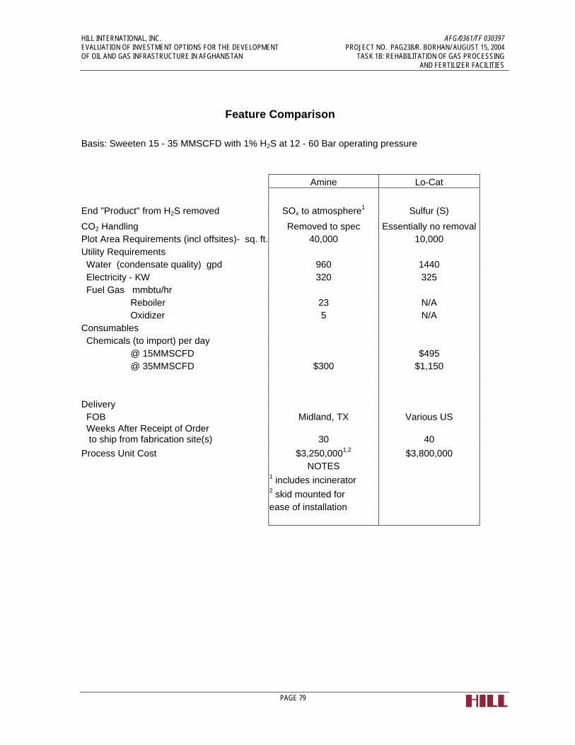
HILL INTERNATIONAL, INC. AFG/0361/TF 030397 EVALUATION OF INVESTMENT OPTIONS FOR THE DEVELOPMENT PROJECT NO. PAG238/R. BORHAN/ AUGUST 15, 2004 OF OIL AND GAS INFRASTRUCTURE IN AFGHANISTAN TASK 1B: REHABILITATION OF GAS PROCESSING AND FERTILIZER FACILITIES
PAGE 79
Feature Comparison
Basis: Sweeten 15 - 35 MMSCFD with 1% H2S at 12 - 60 Bar operating pressure Amine Lo-Cat
End "Product" from H2S removed SOx to atmosphere1 Sulfur (S)
CO2 Handling Removed to spec Essentially no removal Plot Area Requirements (incl offsites)- sq. ft. 40,000 10,000 Utility Requirements Water (condensate quality) gpd 960 1440 Electricity - KW 320 325 Fuel Gas mmbtu/hr Reboiler 23 N/A Oxidizer 5 N/A Consumables Chemicals (to import) per day @ 15MMSCFD $495 @ 35MMSCFD $300 $1,150 Delivery FOB Midland, TX Various US
Weeks After Receipt of Order to ship from fabrication site(s) 30 40
Process Unit Cost $3,250,0001,2 $3,800,000 NOTES 1 includes incinerator 2 skid mounted for ease of installation

HILL INTERNATIONAL, INC. AFG/0361/TF 030397 EVALUATION OF INVESTMENT OPTIONS FOR THE DEVELOPMENT PROJECT NO. PAG238/R. BORHAN/ AUGUST 15, 2004 OF OIL AND GAS INFRASTRUCTURE IN AFGHANISTAN TASK 1B: REHABILITATION OF GAS PROCESSING AND FERTILIZER FACILITIES
PAGE 80
Figure 3-2: Sketches of Gas Treating Options
Iron Sponge System
Water
Natural Gas
Treated Gas To Dehydration
Media Media
Spent Sponge
Spent Sponge

HILL INTERNATIONAL, INC. AFG/0361/TF 030397 EVALUATION OF INVESTMENT OPTIONS FOR THE DEVELOPMENT PROJECT NO. PAG238/R. BORHAN/ AUGUST 15, 2004 OF OIL AND GAS INFRASTRUCTURE IN AFGHANISTAN TASK 1B: REHABILITATION OF GAS PROCESSING AND FERTILIZER FACILITIES
PAGE 81
Amine System
Optional Equipment
Reclaimer
Outlet Separator
Sweet Gas
Sour Gas
Condenser
Flash Gas
Rich/Lean Exchanger
Lean Cooler
Flash Tank
Reflux Separator
Inlet Separator
ContactorStripper

HILL INTERNATIONAL, INC. AFG/0361/TF 030397 EVALUATION OF INVESTMENT OPTIONS FOR THE DEVELOPMENT PROJECT NO. PAG238/R. BORHAN/ AUGUST 15, 2004 OF OIL AND GAS INFRASTRUCTURE IN AFGHANISTAN TASK 1B: REHABILITATION OF GAS PROCESSING AND FERTILIZER FACILITIES
PAGE 82
Iron Redox System
Sulfur Storage
Wash Water
Vacuum Belt Filter
Vent
Sour Gas
Oxidizer
Absorber
Inlet Separator
Treated Gas To Dehydration
Air

HILL INTERNATIONAL, INC. AFG/0361/TF 030397 EVALUATION OF INVESTMENT OPTIONS FOR THE DEVELOPMENT PROJECT NO. PAG238/R. BORHAN/ AUGUST 15, 2004 OF OIL AND GAS INFRASTRUCTURE IN AFGHANISTAN TASK 1B: REHABILITATION OF GAS PROCESSING AND FERTILIZER FACILITIES
PAGE 83
3.6 Recommendations
There are two primary issues that present difficulties in recommending a firm course of action for gas processing plant facilities in Afghanistan:
• The lack of a definitive projection of gas production capability of the existing and future production fields to realistically define the target production rates, quality and the incoming gas specifications.
• The lack of any documentation on the Jarquduk processing facility, and the unknown actual physical condition of the equipment at the plant.
Despite these issues, the Consultant has, using best available information, made assumptions as to the production profile (outlined in section 4.3 of this report) and physical condition (based on plant inspections, sections 4.1.1 and 4.1.2 of this report) in order to present a realistic yet flexible set of recommendations on how to proceed with the task of gas processing in Afghanistan.
It should be noted that the Consultant has assumed a very conservative H2S content of 1% for the combined, blended gas output from all of the fields. This figure is most likely on the high side, given Afghan and Soviet data currently available, although some inconsistencies in this data have led the Consultant to consider this a reasonable figure for planning and conceptual design purposes.
The Consultant recommends a graduated, flexible program for gas processing consisting of the following options, all of which are priced and described in further detail in section 4.4 of this report :
• For a short term production rate of 15 to 35 MMSCFD with a 0.03 wt. % H2S content or lower, i.e. if the sulfur removal rate is limited to only around 250 Kg/day, a new iron sponge unit can be considered.
• For a short term production rate of 15 to 35 MMSCFD, but at worst case H2S level of up to 1 wt. %, an iron redox type unit such as the Lo Cat H2S Removal System can be considered. For higher future gas flow rates, an additional iron redox train could be installed to accommodate the increased flow/production.
• For the medium-term anticipated production rate of 70-100 MMSCFD, the three options are a new Amine gas treating system including sulfur recovery, an additional iron redox train or iron sponge unit, or a partial rehabilitation of the existing Jarquduk gas plant treating unit, with a new sulfur recovery unit installed. Given the reasonable state of the existing Jarquduk Plant, and assuming plant turndown capability is met, the consultant believes it is unlikely that a grass roots plant will be justified or necessary. The cost of the sulfur recovery unit would then be simply the process unit cost as shown in the preceding estimates.
These are the specific recommendations for the given conditions and characteristics of the Afghanistan gas wells, gas production and existing Jarquduk gas plant. These recommendations can help determine which alternatives or options are not viable based upon the given gas flow rates and sulfur content. In order to perform further evaluations of

HILL INTERNATIONAL, INC. AFG/0361/TF 030397 EVALUATION OF INVESTMENT OPTIONS FOR THE DEVELOPMENT PROJECT NO. PAG238/R. BORHAN/ AUGUST 15, 2004 OF OIL AND GAS INFRASTRUCTURE IN AFGHANISTAN TASK 1B: REHABILITATION OF GAS PROCESSING AND FERTILIZER FACILITIES
PAGE 84
specific H2S removal systems adequate for the gas in Afghanistan there are several steps that need to be performed.
A thorough evaluation of the production potential of the existing and future gas fields is needed. This will help in setting a realistic gas composition, including H2S and CO2 levels. The range of H2S content varies widely among the various gas fields located in Afghanistan and needs to be confirmed once wells are brought online.
The gas treating unit must be designed to handle the anticipated ranges of H2S content and pressure. The production rate and the treated gas quality will depend upon gas field production capabilities, the industrial users and their specific needs for a higher quality or sweet gas than other industrial users. Information will be needed on the gas composition from the subject Afghanistan gas wells. In order to evaluate how the existing Jarquduk gas complex will perform with a subject gas feedstock, an accurate composition and characteristic of the gas feedstock is needed. This will set the design basis for evaluating the overall plant performance and help determine what, if any, modifications would be required on the existing Jarquduk gas complex. The information on the gas composition and wells would consist of the following:
• Upstream Well Information (locations and distances)
• Gas Composition From Each Well
• Gas Pressures From Each Well
• Temperatures From Each Well
• Flow Rates From Each Well
• Pipeline Information (sizes, locations and distances)
• Pipeline System Detail (reflecting launchers, receivers, valves, filters, etc.)
An engineering team would need to be assembled to go and inspect/capture this stated data on the Afghanistan gas wells and gas delivery system, once they are online. In order to continue evaluating the existing Jarquduk gas complex and the most feasible methods for treating the sour gas, several key pieces of information will be needed prior to performing this assessment. Most of the information is needed to perform detailed process evaluations. Additional information needed on the existing Jarquduk gas complex would consist of the following:
• Process Flow Diagrams (PFDs)
• P&IDs
• Heat and Material Balances
• Equipment Data Sheets or Specifications
• Piping Line List
• Instrument Index
• Electrical One Lines
• Electrical Load List
• Rotating Equipment Data Sheets or Information

HILL INTERNATIONAL, INC. AFG/0361/TF 030397 EVALUATION OF INVESTMENT OPTIONS FOR THE DEVELOPMENT PROJECT NO. PAG238/R. BORHAN/ AUGUST 15, 2004 OF OIL AND GAS INFRASTRUCTURE IN AFGHANISTAN TASK 1B: REHABILITATION OF GAS PROCESSING AND FERTILIZER FACILITIES
PAGE 85
As most of this data is not available on the existing Jarquduk gas complex, an engineering team would need to investigate and acquire the needed information at the facility. The engineering team would have to perform system walk downs in order to prepare actual P&IDs, acquire equipment name plate information, develop the piping line list and identify piping specification breaks. The instrument and electrical data for motors and controls would also need to be acquired from the facility to understand the power/load constraints as well as the control logic and control system(s). This information is needed in order to perform an adequate process performance evaluation of the existing facility. As previously discussed in this report, a detailed mechanical and operational integrity review should also be performed at the existing Jarquduk gas complex on the existing equipment to verify that all systems work correctly and safely.
Once this information is obtained and defined, for both the sour gas supply and the existing Jarquduk gas complex, a thorough and detailed evaluation can be performed to determine the expected results of the Jarquduk gas plant and the associated final gas product(s).
3.7 Program for Training Afghanis in Operations and Management
The lack of trained, qualified personnel presents a significant challenge to any facility operating in Afghanistan. In the case of any new processing facility, the present manpower working at the two gas processing plants, except perhaps for a very small percentage, is not considered suitable or even trainable to manage and operate a modern processing plant utilizing latest efficient Western technology, with sophisticated electronic instrumentation and energy-efficient designs.
On the other hand, if it is determined that the current Jarquduk Plant, with modifications, is usable for processing the new gas stream, then the training requirements will be considerably reduced, although they will still present a challenge.
In the former case, it is likely that when new drilling programs are undertaken and a larger supply of gas becomes available, custom-designed gas-processing plants will have to be built to process these gas supplies and produce badly needed urea fertilizer. These plants will be designed incorporating the most modern technology using up-to-date electronic control systems.
Such plants will require teams of young and well-trained engineers, operators, technicians and administrators to manage, operate and maintain them with high efficiency and reliability.
Each of these plants will be headed by a Plant Manager, who should be technically qualified and experienced, as well as a strong administrator and leader. He will have the following functions reporting to him:
• Operations Manager - covering plant operations and a technology group for trouble-shooting, including chemical engineers, shift supervisors and plant operators

HILL INTERNATIONAL, INC. AFG/0361/TF 030397 EVALUATION OF INVESTMENT OPTIONS FOR THE DEVELOPMENT PROJECT NO. PAG238/R. BORHAN/ AUGUST 15, 2004 OF OIL AND GAS INFRASTRUCTURE IN AFGHANISTAN TASK 1B: REHABILITATION OF GAS PROCESSING AND FERTILIZER FACILITIES
PAGE 86
• Engineering Manager - covering the maintenance and projects group, including mechanical, electrical, instrument and civil engineers, craft supervisors, maintenance foremen, workshop and field technicians
• Administration Manager - covering the functions of Personnel, General Administration (incl. Public Relations), Finance, Medical and Security
• Materials Manager---covering the procurement of spares and consumables, and stores functions, and ensuring the availability of spares and consumable materials.
For manning the senior positions, a search should be carried out to find well-educated and experienced Afghan nationals both within the country and outside. There are a large number of well-qualified Afghans who are currently working in Western Europe and North America. Many of them have a desire to return and participate in the rebuilding of their nation. There is strong possibility that some of them with requisite qualification and experience can be hired and brought back, once they are able to see future prospects for a good career in their own home country.
In order to staff levels lower than managers, the first step would be to carry out a complete inventory of the entire manpower under the Afghan Gas Co. and the Kud Bergh plants, including the personnel engaged at the plants at all levels. This inventory will have to be carried out by a team of professionals who have run such a facility in amore modern atmosphere. Those existing personnel who have the requisite educational background and have the potential of being trained should be sent out to a gas-processing plant or a Fertilizer Plant outside Afghanistan. Selection of such a location can be carried out in consultation with the Design companies engaged for the new plants. The balance of the requirement should then be clearly identified and following course of action taken:
• Advertise and hire engineers, operating and maintenance staff.
• The engineers should hold at least a bachelors degree in their field, with good grasp of the subject and should be fluent in English so that they can be trained in modern technology from the West. They should then be sent for a 12-18 months training in an operating plant of similar design in a Third World country (cost and culture consideration). This training program should be specifically developed for their needs and should have classroom as well as practical work training.
• For operators and technicians, high school graduates with English, Mathematics and General Science (Physics and Chemistry) should be recruited. They should be given further training in these subjects and then be sent to a technical school where special programs should be followed to prepare them for their specific field of work. The technical school period should be 18-24 months and the training should prepare them to take the job as junior technicians or operators under an experienced expatriate worker with prospect of working independently in about two years time.
• For functions under the Administration and Materials, same hiring criteria should be used as that for operating and maintenance personnel. However, their training should be carried out within Afghanistan under more experienced Afghan and expatriate professionals in their respective fields at the plant.

HILL INTERNATIONAL, INC. AFG/0361/TF 030397 EVALUATION OF INVESTMENT OPTIONS FOR THE DEVELOPMENT PROJECT NO. PAG238/R. BORHAN/ AUGUST 15, 2004 OF OIL AND GAS INFRASTRUCTURE IN AFGHANISTAN TASK 1B: REHABILITATION OF GAS PROCESSING AND FERTILIZER FACILITIES
PAGE 87
Once gas availability has been ascertained through the servicing of the wells and additional well drilling and a decision taken to set up gas processing plants or a new fertilizer plant, the recruitment activity should be started without any delay. Their training program should be started immediately and they should start work under the direct supervision of expatriate staff whose presence in the early period of new plant operation is essential. However, a clear-cut policy should be established to replace the expatriate staff with Afghan nationals as soon as they show the ability to handle the job.
The training of engineers outside Afghanistan is also a very important component of the program. The choice of the organization where the training is arranged should be made with great care, as the management culture and work practices of the training location is bound to creep into the new organization. A bad management culture can be very damaging to a new/reconditioned organization in Afghanistan and may take a long time to rectify, once its ill-effects are recognized.

HILL INTERNATIONAL, INC. AFG/0361/TF 030397 EVALUATION OF INVESTMENT OPTIONS FOR THE DEVELOPMENT PROJECT NO. PAG238/R. BORHAN/ AUGUST 15, 2004 OF OIL AND GAS INFRASTRUCTURE IN AFGHANISTAN TASK 1B: REHABILITATION OF GAS PROCESSING AND FERTILIZER FACILITIES
PAGE 88
4.0 Fertilizer Plant at Qala Jangi
4.1 Background
The Kud Bergh5 facility has two separate plants - the Fertilizer Plant and the Power Plant. Both plants have distinct status and purpose and will be discussed separately in Sections 4.0 and 5.0. Although both the plants were built during the same period (1967-74), the Fertilizer plant was based on very outdated manufacturing technology that was abandoned soon after World War II, due to complexity of process and excessive equipment needs, and resulting in high investment costs, maintenance costs and energy wastage. The Power Plant, on the other hand, is a conventional steam boiler/turbine generator system that continues to be a viable and successful method of power generation.
4.2 Overall Plant Condition
The Kud Bergh Fertilizer Plant was built by the Soviet Union from 1967 to 1973. It has a rated capacity of 200 MT per day of ammonia (through two lines of 100 MT/day) and 300 MT per day of urea (through three lines of 100 MT/day).
Annual design production capacity of urea is 105,000 MT. However, due to gas shortages and the deteriorating condition of the plant, the current annual production level is at only 40,000 MT, utilizing only one line of ammonia and one line of urea. Due to shortage of spares, many pieces of machinery and equipment have been cannibalized.
The Fertilizer Plant uses a process technology that was abandoned in the 1950s using air separation for the production of nitrogen, while hydrogen is produced by low pressure steam reforming. The nitrogen and hydrogen so produced are synthesized to produce ammonia, which is then reacted with the carbon dioxide by-product to produce urea.
4.3 Physical Inspection Report
The summary inspection report of the Fertilizer Plant at Qala Jangi is presented in this section.
5 Literally, Kud = Fertilizer and Berq (Bergh) = Electricity

HILL INTERNATIONAL, INC. AFG/0361/TF 030397 EVALUATION OF INVESTMENT OPTIONS FOR THE DEVELOPMENT PROJECT NO. PAG238/R. BORHAN/ AUGUST 15, 2004 OF OIL AND GAS INFRASTRUCTURE IN AFGHANISTAN TASK 1B: REHABILITATION OF GAS PROCESSING AND FERTILIZER FACILITIES
PAGE 89
SUMMARY INSPECTION REPORT OF KUD BERGH FERTILIZER PLANT
Plant Detail
Location of Plant Near Qala Jangi, 30 km from Mazar-E-Sharif Plant Commissioned date 1973 Anhydrous Ammonia Two production lines
(Two Ammonia Convertors) 2 x 100 MT= 200 MT/Day Prilled Urea Three Production Lines
(Three Urea Reactors) 3x100 MT = 300 MT / Day Quality of Urea Prills Nitrogen > 46% Biurete < 1.5% Moisture < 0.3% Size of Prill > 1-2.5 mm, 90%
Details of Major Equipment and Machinery
Ammonia Unit
Centrifugal Compressors for Air Liquefaction 4 Nos. 8200 cubic m/Hr. 7.8 kg/cm²
Electric motor 800 KW – 6 KV 89 AMP, 50 Cycle Reciprocating Compressors, Motor Driven for Air Liquefaction 4 Nos. Centrifugal Compressor for oxygen 2 Nos. Reciprocating Compressor for Ammonia Gas 4 Nos. Discharge Pressure 15 kg/cm² Reciprocating Compressor for Hydrogen 2 Nos. and Nitrogen (Syn Gas) Discharge Pressure 320 kg/cm² Cooling Tower 10 Cell Ammonia Reactors, Vertical and Radial Flow 2 Nos.
Urea Unit
High Pressure Carbamate plunger pumps 6 Nos. Make Uraca Germany, Nikkipiso Japan. Ammonia Plunger Pumps 4 Nos. Make PAX, Czechoslovakia

HILL INTERNATIONAL, INC. AFG/0361/TF 030397 EVALUATION OF INVESTMENT OPTIONS FOR THE DEVELOPMENT PROJECT NO. PAG238/R. BORHAN/ AUGUST 15, 2004 OF OIL AND GAS INFRASTRUCTURE IN AFGHANISTAN TASK 1B: REHABILITATION OF GAS PROCESSING AND FERTILIZER FACILITIES
PAGE 90
Urea Reactor 3 Nos. CO2 Reciprocating compressor 5 stage Make Mannesman Germany 200 Atms Discharge pressure Prill Tower Concrete Structure with evaporator at top. Urea Conveyers and bag storage.
Gas Supply
The gas is being supplied from the Sheberghan Gas Fields, located about 100 Km away from the plant, by a 320 mm pipeline. The supply of the gas has gone down considerably over the years. When the plant was started, it was receiving about 700,000 M3/day of gas at a pressure of 14-15 atmospheres (about 220 psig). Currently, only 300,000 M3/day at about 4 atms is available, both for feed to the ammonia plant and fuel for the power plant. This has resulted in the curtailment of production of both urea and power.
The gas being supplied to the plant is essentially sweet and contains only 0.6 mg/ M3 of sulfur (0.84 ppm). It has 97% methane and a calorific value of approximately 1000 BTU/CuFt. Sour gas would contaminate the catalyst beds, and so would normally need to be treated before use in a fertilizer plant.
Water Supply
Water is being pumped from the Balkh River, which is about 2Km away. Three electric pumps are installed at the pumping station. Currently only one is running, supplying 630 M3/Hr (approx. 2800 gpm). This meets the needs of the plant for the boilers, cooling towers and potable supply. Water treatment consists of alum treatment, filtration and zeolite softening for supply to boilers. There are two cooling towers of 5 cells each for the fertilizer plant and three cooling towers of 3 cells each for the power plant. Due to low plant load only half of these are in use.
Ammonia Plant
The Ammonia Plant is based on an obsolete design that was abandoned around 1960, due to excessive energy consumption per ton of ammonia (and urea) produced. The plant was built by Chemexport of the Soviet Union at Qala Jangi near Mazar-e-Sharif in the late sixties and took six years to complete in 1973. It uses an air separation process for the supply of nitrogen to make ammonia. It has two lines for the production of 200 MT per day of ammonia, requiring the use of numerous reciprocating compressors of small sizes, consuming excessive electric power. It also involves heavy energy expenditure on a much larger number of machinery units.
By the late 1960s, the technology for making ammonia had advanced by two stages:
• The introduction of high pressure Reforming Furnaces, followed by a Secondary Reformer where compressed air was supplied directly into feed stream after the Primary Reformer eliminated the need for the Air-Separation

HILL INTERNATIONAL, INC. AFG/0361/TF 030397 EVALUATION OF INVESTMENT OPTIONS FOR THE DEVELOPMENT PROJECT NO. PAG238/R. BORHAN/ AUGUST 15, 2004 OF OIL AND GAS INFRASTRUCTURE IN AFGHANISTAN TASK 1B: REHABILITATION OF GAS PROCESSING AND FERTILIZER FACILITIES
PAGE 91
Plant, which is very energy-consuming. Several other refinements were made in the design, such as the addition of LowTemp Shift Converters and Methanators to improve efficiency and life of the synthesis catalyst. This resulted in the design of larger plants that could produce 300+ tons per day of ammonia and 500+ tons per day of urea. As a result, the number of equipment, particularly the high power-consuming compressors were reduced significantly.
• The switch to Centrifugal Compressors in place of Reciprocating Compressors, resulting in larger single-train plants of 600 MeTons/day of ammonia (for a 1000 MeTons/day of urea plant) and higher. This resulted in better efficiency in gas usage and higher reliability.
Fertilizer plants using this new design and technology reduced the total gas consumption per ton of urea to about 24-26 million BTUs, as compared to the current consumption of over 81 million BTUs at Mazar-e-Sharif. Even at its full production rate, it is estimated that the Mazar-e-Sharif plant was using about 65-70 million BTUs to produce one ton of urea. It should be noted that a significant portion of the energy efficiency comes from very good process control using modern control systems, which this plant lacks.
Urea Plant
The Urea Plant has three lines of 105 MT each and uses two-stage decomposition and recovery. Again, like the ammonia plant, it triplicates equipment (compressors for carbon dioxide as well as very high maintenance ammonia and carbamate pumps). The two-stage decomposition and recovery yields a very low conversion ratio of ammonia to urea.
Two other weaknesses were observed in the urea plant design. The three urea reactors have titanium linings. These linings are generally very thin due to the high cost and are easily perforated. About the time this plant was built, stainless steel 316L liners had been introduced with oxygen pacification that proved highly reliable and robust. The second issue that was observed was the low height of the Prill Tower. This results in small urea prills which are considered inferior.

Annex 4.3-1
FERTILIZER PLANT
Inspection Report of Ultrasonic Wall Thickness and Hardness Testing of Critical Equipment of Ammonia Plant
Sr. No. Equipment / Vessel No. Thickness (mm) Hardness (HB)
1 609 - II Liquid Horizontal Tank 15.9, 15.8, 15.6 212
2 401 - I Ammonia Converter103.0 17298.3 200
3 401 - II Ammonia Converter98.1 17599.2 188
4 601 - I Ammonia Reactor 136.2 283
5 601 - II Ammonia Reactor 138.0 266
6 602 - I Vertical Vessel 10.2 240

Annex 4.3-2
Legend H = Horizontal
V = Vertical
A = Axial
Ref. Point
A 0.295 ~ 0.298
FERTILIZER PLANT
Compressor Inspection Report
Reading Range in/secLocationVibration Inspection Report Oxygen Compressor No. BTKN - 2
Reading Range in/secLocation Ref. Point
H 0.480 ~ 0.482
V 0.385 ~ 0.387
Ref. Point Location Reading Range in/sec Ref. Point
1 V
H
2
A 0.295 ~ 0.298
0.385 ~ 0.387
0.331 ~ 0.347
0.530 ~ 0.539
H 0.212 ~ 0.215
V 0.405 ~ 0.416
Ref. Point Location Reading Range in/sec
Location Reading Range in/sec
Vibration Inspection Report Oxygen Compressor No. KBNH - 2
4
H 0.763 ~ 0.767
V3
Ref. Point Location Reading Range in/sec
A 0.017 ~ 0430
2
H 0.119 ~ 0.121
V 0.680 ~ 0.690
A 0.205 ~ 0.207
3
H 0.087 ~ 0.089
V 0.121 ~ 0.123
A 0.146 ~ 0.202
A -
43
21
MotorFan

Multi Stage CO2 Compressor Urea Unit
Centrifugal Compressor Deck Ammonia Unit
Inter Stage Piping of Reciprocating Compressor Urea Unit
Ammonia Compressor
FERTILIZER PLANT

Instrument Panel Compressor Deck
Ammonia Compressor
Piping Network of Ammonia Plant
Canbamate Piping Urea Unit
FERTILIZER PLANT

Water Treatment Plant
Two Stage Air Compressor
Control Room Urea Unit
FERTILIZER PLANT
Air Liquification Section Ammonia Unit

High Pressure CO2 Piping Network
Spare Valves - Stone Yard
Ammonia Plunger Pumps
High Pressure Plunger Pumps Urea Unit
FERTILIZER PLANT

Ammonia Feed Pumps Urea Unit
URACA Canbamate Plunger Pumps
Vertical Vessels of Ammonia Plant (Synthesis Section)
Ammonia Converter
FERTILIZER PLANT

Heat Exchangers (Synthesis Section Ammonia Unit)
Heat Exchangers (Refregeration Section Ammonia Unit)
Heat Exchangers (Synthesis Section)
Vertical Vessels of Ammonia Plant
FERTILIZER PLANT

HILL INTERNATIONAL, INC. AFG/0361/TF 030397 EVALUATION OF INVESTMENT OPTIONS FOR THE DEVELOPMENT PROJECT NO. PAG238/R. BORHAN/ AUGUST 15, 2004 OF OIL AND GAS INFRASTRUCTURE IN AFGHANISTAN TASK 1B: REHABILITATION OF GAS PROCESSING AND FERTILIZER FACILITIES
PAGE 100
4.4 Key Findings
4.4.1 Antiquated Process
The Plant’s Process Design and Equipment are of antiquated technology and use excessive power for production of urea. The energy consumption per ton of Urea produced is twice to three times that of other, more modern processes.
Fertilizer plants using newer design and technology have a total gas consumption per MT of urea of about 24-26 million BTUs6, as compared to the current consumption of over 81 million BTUs at Mazar-e-Sharif. Even at its full production rate, it is estimated that the Mazar-e-Sharif plant was using about 65-70 million BTUs to produce one ton of urea. A significant portion of the energy reduction comes from very good process control using modern control systems, which this plant lacks.
4.4.2 Unavailability of Spare Parts
Due to the non-availability of spares, one Urea Reactor and other related equipment are not in operation. Spares are being cannibalized. Out of six Carbamate pumps only two are working. In order to keep the plant in operation, only one line of Ammonia and two lines of Urea are in operation. The condition of Pressure Vessels and Heat Exchangers is very poor. Vital spare parts for machinery are not available and very difficult to obtain.
The procedure for procuring the spare parts is difficult and bureaucratic. When the need for spares is established by the plant, the requisition is sent to the Ministry of Mines and Industry (MMI) in Kabul with the description of the spares and of the machinery for which they are required. This is a difficult task since no drawings and manuals are available. With the limited information at its disposal, the MMI contacts a number of Trading Houses and asks them to procure the spares from their contacts in Eastern Europe and former Soviet Republics. Sometimes they are successful in obtaining the parts from old warehouses or from a mothballed or closed factory. This takes an inordinately long period. Should the spare parts not be available, the unit that needs the part is either shut down or the spare installed machinery is
6 Source: PotashCorp
Nitrogen Production Factors
To Produce 1 short ton of: Requires: Ammonia 33.5 MMBtu Natural Gas Urea 24.0 MMBtu Natural Gas Urea Solution 0.58 Tons Ammonia 0.78 Tons CO2 Urea Prills (46% N) 1.01 Tons Urea Solution To Produce 1 metric ton of: Requires: Ammonia 36.93 MMBtu Natural Gas Urea 26.46 MMBtu Natural Gas

HILL INTERNATIONAL, INC. AFG/0361/TF 030397 EVALUATION OF INVESTMENT OPTIONS FOR THE DEVELOPMENT PROJECT NO. PAG238/R. BORHAN/ AUGUST 15, 2004 OF OIL AND GAS INFRASTRUCTURE IN AFGHANISTAN TASK 1B: REHABILITATION OF GAS PROCESSING AND FERTILIZER FACILITIES
PAGE 101
cannibalized, since some production lines are not operating. Several examples of this situation were observed at the plant.
Most engineering companies in the West have discontinued manufacturing the machinery and equipment used in plants built with this outdated technology. In the case of the Kud Bergh Fertilizer Plant, built under the centralized Soviet system, the various pieces of machinery were manufactured in different republics of Soviet Union, which are now sovereign states. With limited demand in their own economies and little likelihood of exports, most of those factories are no longer in business or have gone on to more modern designs for plants and machinery, based on Western technology. They are therefore no longer making the spares required by the Kud Bergh Fertilizer Plant.
4.4.3 Poor Management, Housekeeping and Safety Practices
Another significant reason for the poor performance and condition of the plant is the sub-standard quality of management and technical manpower. Afghanistan went through 23 years of turmoil and conflicts. The area where the plant is located saw several changes of leadership. Under these conditions, those that could leave either went to safer locations within Afghanistan or emigrated. Also, until 1988, many of the senior technical positions were held by Soviet engineers who left without any orderly transfer of responsibility. The vacuum created by these losses at senior levels was filled from within without any regard to the technical or leadership quality.
In the professional cadres, one can find a few competent and dedicated persons who are working hard and trying to keep the plant in operation. In interviews, they sounded enthusiastic as well as bitter and angry due to lack of spares and materials.
Nearly all of the employees currently working in the plant were recruited during the construction and start-up period and are either in their early or mid-fifties. They were hired and trained by the Soviet engineers and display poor management skills. Except for a few, none have been exposed to technical seminars or training.
The standard of management of any chemical plant can best be judged by the observance of safety procedures and general housekeeping in the plant areas. The Fertilizer plant has a manpower variously reported as between 2700 and 3000. Yet nearly all the plant areas were littered with components of equipment and machinery and scrap material. Many of these items were salvageable and should have been reconditioned for the plant, which is perpetually short of spares and funds to procure them.
On the issue of safety, no one wears safety hats or safety shoes. In operating areas, workers were roaming about in open sandals. Smoking by employees and supervisors was observed in plant areas. The litter lying all over the plant is also a safety hazard. The green areas are overgrown and the entire plant compound has a shabby, rundown look.
With regard to the workforce (operators and technicians), again the quality is lacking. It was difficult to see a worker in the plant younger than 50. Most of the employees

HILL INTERNATIONAL, INC. AFG/0361/TF 030397 EVALUATION OF INVESTMENT OPTIONS FOR THE DEVELOPMENT PROJECT NO. PAG238/R. BORHAN/ AUGUST 15, 2004 OF OIL AND GAS INFRASTRUCTURE IN AFGHANISTAN TASK 1B: REHABILITATION OF GAS PROCESSING AND FERTILIZER FACILITIES
PAGE 102
were hired during the construction phase of the plant by the Soviet team and were then given some training to work under Soviet foremen. Most do not have any educational background or formal technical training. They were trained to perform tasks under direction and close supervision. During the past 16 years (when the Soviet personnel left) they have done the best they can do to keep the declining number of equipment running. However they are unsuited to be trained to work in a modern design plant employing advanced technology.
The plant runs without proper drawings and manuals. It is quite likely that the Soviet engineers either destroyed them or took them away when they left.
4.4.4 Inadequate Laboratory Facilities
The Central Laboratory of the plant is located on the second floor of the Administration Building. In a plant of this type the laboratory plays a very important role to assist the operating personnel to maintain high efficiency of conversion at various stages of the chemical reaction. It also provides guidance on the efficiency of catalysts and forecasts as to when the various catalysts have to be changed. In addition it plays an important role in the quality control of the product. The laboratory of the plant at Kud Bergh is no more advanced than a high-school laboratory. It has some glassware and chemicals, a few old style balances and a small oven.
4.5 Options for Rehabilitation or Replacement
A careful review of the Fertilizer Plant has been made to see if it can be rehabilitated to perform at levels for which it was designed. This study is especially critical due to the sharp increase in the demand for urea fertilizer by the agricultural community, and the high price of imported fertilizer.
The Consultant is of the opinion that the Fertilizer Plant cannot be rehabilitated to produce fertilizer effectively and at a reasonable price for the following reasons:
• The design of the plant is so obsolete that even if all other constraints are overcome, it will continue to be an extremely inefficient and difficult plant to run. The route of air-separation and low-pressure reforming was abandoned in the 1950s due to very large pieces of moving equipment involved, consuming excessive amount of power and requiring high and costly maintenance. This would continue to be true even with complete upgrading of the control systems. To highlight this point, the Kud Bergh fertilizer plant has a total of 20 compressors, 14 of which are reciprocating. These compressors consume heavy electrical power and require heavy maintenance. A plant built with Western technology in late sixties (the same period when the Kud Bergh plant was built), used centrifugal compressors and high-pressure reforming. Such a plant uses only 4-5 compact centrifugal compressors, requiring low energy and low maintenance.
• A second weakness of the plant is the number of process lines both in the Ammonia and Urea units of the plant. The ammonia unit which is designed to

HILL INTERNATIONAL, INC. AFG/0361/TF 030397 EVALUATION OF INVESTMENT OPTIONS FOR THE DEVELOPMENT PROJECT NO. PAG238/R. BORHAN/ AUGUST 15, 2004 OF OIL AND GAS INFRASTRUCTURE IN AFGHANISTAN TASK 1B: REHABILITATION OF GAS PROCESSING AND FERTILIZER FACILITIES
PAGE 103
produce 200 tons of ammonia employs two lines of 100 Tons per day. This was at a time when single lines of 600 Tons per day were being installed. Similarly, the urea unit has three lines of 100 Tons per day, whereas the norm at that time was 1000 Tons per day. This has resulted in 2 to 3 times the equipment to produce less than one third the quantity of urea, with excessive maintenance workload.
• These inefficiencies can be best quantified by observing that the fertilizer plant is currently producing 40,000 tons of urea fertilizer per year, consuming over 80 MMBTUs of energy per ton of urea produced. Modern plants use 24 to 26 MMBTUs of energy per ton of urea. Even at a modest gas price of $3.00 per MMBTU, only the differential of over 50 MMBTU per ton results in a difference of $150 per ton of urea. This can be compared with the FOB price of bulk Urea in the Middle East within a range of $130 to $150 per ton.
• The Fertilizer Plant is over 30 years old. It was built by a Soviet Export Clearing House which procured all the machinery and equipment from the centrally-planned economy units within Soviet Union. Due to the break-up of Soviet Union, various republics that supplied the numerous components of the plant have their own agenda for their industries. As a result, many of the factories that supplied equipment have either closed down or have moved on to newer technologies, abandoning the designs and manufacturing facilities for the components of the plant. The prospect of obtaining the large number of machinery components and spares necessary to rehabilitate the plant is therefore most unlikely, if not impossible.
• The Kud Bergh plant is facing serious problems in purchasing spares and has cannibalized the plant extensively. It is the Consultant’s opinion that even if full gas supply is restored to the plant, it will not be able to run the plant at anything close to full load. In the Air Separation Plant, four reciprocating compressors are installed to compress air for liquification. Out of the four units, only one is currently running. This compressor requires several critical spares that are not available. As a result, the compressor is unable to raise the air pressure to design levels. The four stages of the compressor are designed to raise the pressure from an inlet pressure of 6 atm. to 17, 50, 110 and 220 atm. Instead, it can only take the pressures up to 11, 40, 65, and 135 atm through the four stages. The condition of the other three compressors in similar service which are currently inoperative is even worse.
• There are no manuals or drawings available to refer to when a crisis situation arises. The engineers who have been working in the plant since its construction and start-up use their memory and ingenuity to continue running the plant even at the reduced rate. During the visit in April, several instances of these problems were brought to notice, relating to some important and critical equipment that have been rendered inoperable due to lack of spares and failure to find the source of original equipment.

HILL INTERNATIONAL, INC. AFG/0361/TF 030397 EVALUATION OF INVESTMENT OPTIONS FOR THE DEVELOPMENT PROJECT NO. PAG238/R. BORHAN/ AUGUST 15, 2004 OF OIL AND GAS INFRASTRUCTURE IN AFGHANISTAN TASK 1B: REHABILITATION OF GAS PROCESSING AND FERTILIZER FACILITIES
PAGE 104
4.6 Fertilizer Demand
4.6.1 Background
Fertilizer use in Afghanistan was introduced in 1962 by the Spinzar Company with the import of 5,000 mt of ammonium nitrate for cotton and sugar beets sown in Konduz, Takhar, and Baghlan7. Later the Ministry of Agriculture started importing and distributing fertilizers. Gradually as fertilizer consumption increased, the Ministry was unable to handle it and created a parastatal in 1972—the Afghan Fertilizer Company (AFC), which later became the Afghan Fertilizer and Agricultural Services Enterprise (AFASE). This organization imported, stored, and distributed fertilizers throughout Afghanistan and sold directly to farmers and through franchised dealers or commission agents. Later, a urea plant with an annual capacity of 105,000 tons was built at Mazar-e-Sharif with Soviet technology and assistance and based on local gas.
It is estimated that over 60% of the fertilizer is used on wheat, 15% on cotton, and the 25% balance on grapes, potatoes, rice, vegetables, sorghum, and other crops. The highest amount of fertilizer distributed by AFASE was 79,000 tons, which includes 52,800 tons of urea and other nitrogenous compounds and 26,200 tons of phosphate fertilizers. This occurred during the 1987/88 cropping season. With the outbreak of civil strife during 1991/92, several institutions, including AFASE, stopped functioning. But since agriculture and farming remained the mainstay of most of the population, the demand for fertilizer continued; the private fertilizer dealers filled the void and began to procure urea from the Mazar-e-Sharif urea plant. These dealers imported the balance from Pakistan, Iran, and Uzbekistan and distributed it throughout Afghanistan. Several nongovernmental organizations (NGOs) also started importing and distributing small quantities of fertilizers during this period.
In 2001/02 the fertilizer consumption in Afghanistan was about 170,000 tons, and it is expected to exceed 300,000 this year. Urea accounted for more than 75% of demand in 2001/2, and over 50% of demand in 2003/4. Other fertilizers were diammonium phosphate (DAP), nitrophosphate (NP), single superphosphate (SSP), calcium ammonium nitrate (CAN), and ammonium nitrate (AN).
4.6.2 Fertilizer Consumption
Based on the discussions with dealers and importers engaged in this field, the Consultant initially arrived at the following fertilizer consumption figures for 2003:
• Urea 160,000 to 200,000 Tons • DiAmmonium Phosphate (DAP) 40,000 to 50,000 Tons • Potash (as SOP,MOP or Compounds) 15,000 to18,000 Tons
7 IFDC, The Rebuilding of Afghanistan’s Agriculture: The IFDC Solution, October 2003

HILL INTERNATIONAL, INC. AFG/0361/TF 030397 EVALUATION OF INVESTMENT OPTIONS FOR THE DEVELOPMENT PROJECT NO. PAG238/R. BORHAN/ AUGUST 15, 2004 OF OIL AND GAS INFRASTRUCTURE IN AFGHANISTAN TASK 1B: REHABILITATION OF GAS PROCESSING AND FERTILIZER FACILITIES
PAGE 105
Fertilizer demand figures for Afghanistan have been badly influenced by the economic condition of the farmers who have lost most of their assets during the last 25 years and are in the process of re-establishing themselves on their farms. If they are given 2 or 3 years of relative calm and peace, the figures may easily rise at a rate of 15-25% per annum, and a consumption of 350,000 Tons of urea in three years cannot be ruled out.
Currently, only about 40,000 Tons of urea is locally produced. The balance of urea and all the other fertilizers are being imported or smuggled from Pakistan and Iran. The smuggled urea is generally adulterated sometimes with harmful materials for the agriculture. If the import is undertaken on a more organized manner by the Government from Persian Gulf producers, the farmers will benefit both in terms of price and quality.
Figure 4-1 below shows past and current Production, Import and Consumption figures for all Fertilizers as well as for Urea only.
Figure 4-1: Afghanistan - Production, Import and Consumption for Fertilizers Source: FAOSTAT data, 2004 (1975-2001); IFDC Survey 2002 (2002-2003)

HILL INTERNATIONAL, INC. AFG/0361/TF 030397 EVALUATION OF INVESTMENT OPTIONS FOR THE DEVELOPMENT PROJECT NO. PAG238/R. BORHAN/ AUGUST 15, 2004 OF OIL AND GAS INFRASTRUCTURE IN AFGHANISTAN TASK 1B: REHABILITATION OF GAS PROCESSING AND FERTILIZER FACILITIES
PAGE 106
A recent survey by IFDC, who is working in Afghanistan under a USAID program, indicated the fertilizer market for Afghanistan at 300,000 Mt per year, including 150,000 MT per year of Urea.
Table 4-A: Afghanistan – Fertilizer Supply and Market Afghanistan Fertilizer Data, Based on IFDC Survey 2002
Fertilizer Dealers Fertilizer, mt
Spring Summer Fall Total Urea 374 71,930 27,584 52,034 151,548 CAN 83 4,451 3,957 5,005 13,413 AN 117 3,428 1,198 1,368 5,994 SSP 146 2,688 840 2,997 6,525 NP 229 11,428 7,067 15,586 34,081 DAP 373 23,706 12,797 38,296 74,799 MAP 200 1,670 612 3,352 5,634 TSP 117 2,695 336 5,758 8,789
TOTAL 1,410 121,996 54,391 124,396 300,783
Source: IFDC
Central Statistical Department estimates indicate slightly lower numbers, presented in table 4-B on the following page by total fertilizer consumption by province.
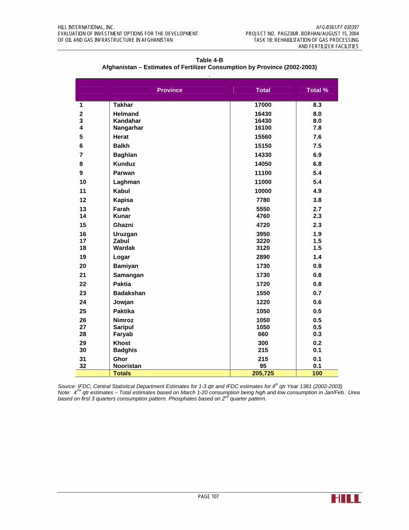
HILL INTERNATIONAL, INC. AFG/0361/TF 030397 EVALUATION OF INVESTMENT OPTIONS FOR THE DEVELOPMENT PROJECT NO. PAG238/R. BORHAN/ AUGUST 15, 2004 OF OIL AND GAS INFRASTRUCTURE IN AFGHANISTAN TASK 1B: REHABILITATION OF GAS PROCESSING AND FERTILIZER FACILITIES
PAGE 107
Table 4-B Afghanistan – Estimates of Fertilizer Consumption by Province (2002-2003)
.
Province Total Total %
1 Takhar 17000 8.3 2 Helmand 16430 8.0 3 Kandahar 16430 8.0 4 Nangarhar 16100 7.8 5 Herat 15560 7.6 6 Balkh 15150 7.5 7 Baghlan 14330 6.9 8 Kunduz 14050 6.8 9 Parwan 11100 5.4 10 Laghman 11000 5.4 11 Kabul 10000 4.9 12 Kapisa 7780 3.8 13 Farah 5550 2.7 14 Kunar 4760 2.3 15 Ghazni 4720 2.3 16 Uruzgan 3950 1.9 17 Zabul 3220 1.5 18 Wardak 3120 1.5 19 Logar 2890 1.4 20 Bamiyan 1730 0.8 21 Samangan 1730 0.8 22 Paktia 1720 0.8 23 Badakshan 1550 0.7 24 Jowjan 1220 0.6 25 Paktika 1050 0.5 26 Nimroz 1050 0.5 27 Saripul 1050 0.5 28 Faryab 660 0.3 29 Khost 300 0.2 30 Badghis 215 0.1 31 Ghor 215 0.1 32 Nooristan 95 0.1 Totals 205,725 100
Source: IFDC, Central Statistical Department Estimates for 1-3 qtr and IFDC estimates for 4th qtr Year 1381 (2002-2003) Note: 4TH qtr estimates – Total estimates based on March 1-20 consumption being high and low consumption in Jan/Feb. Urea based on first 3 quarters consumption pattern. Phosphates based on 2nd quarter pattern.

HILL INTERNATIONAL, INC. AFG/0361/TF 030397 EVALUATION OF INVESTMENT OPTIONS FOR THE DEVELOPMENT PROJECT NO. PAG238/R. BORHAN/ AUGUST 15, 2004 OF OIL AND GAS INFRASTRUCTURE IN AFGHANISTAN TASK 1B: REHABILITATION OF GAS PROCESSING AND FERTILIZER FACILITIES
PAGE 108
For the purposes of this analysis, the Consultant has assumed a base year 2004 demand of 150,000 Tons of Urea, increasing at 10% per year for three years, and then reducing to a 5% annual increase for the remaining period. The demand projection is shown below in Figure 4-3.
Figure 4-2: Afghanistan –Projected Annual Urea Demand Source: Consultant’s projection
It should be noted that the Consultants did extensive interviews with government officials, NGOs, private dealers and Fertilizer Plant personnel in order to better understand the Afghan fertilizer market. Unfortunately, almost all of the sources provided conflicting information, and the Consultant has had to use selected data based on our own judgment to arrive at fertilizer demand numbers. An interview excerpt, shown below, from an interview with a senior official of the department of Afghan Fertilizer & Agricultural Services of the Ministry of Agriculture, indicates some of the difficulty in obtaining information:
“[the interviewee] gave some ambiguous answers about prices, and did not talk at all about other imports, except urea and ammonia. They have no own statistical data at all and came up with the numbers from the top of his head. However, private business (theoretically) has to report amounts and country of origin to this department. The documents do exist but are not in any particular order. The [interviewee] said he would think about making this data accessible to us. He did not want to mention the names of the main importers.
Information on urea
• imports by private businesses amounts to 400.000 tons/year
• the fertilizer factory produces 40.000 tons/year
HILL INTERNATIONAL, INC. AFG/0361/TF 030397 EVALUATION OF INVESTMENT OPTIONS FOR THE DEVELOPMENT PROJECT NO. PAG238/R. BORHAN/ AUGUST 15, 2004 OF OIL AND GAS INFRASTRUCTURE IN AFGHANISTAN TASK 1B: REHABILITATION OF GAS PROCESSING AND FERTILIZER FACILITIES
PAGE 109
• total demand 450.000 tons/year
• average price 110 -120$/ton but depends on country of origin
• prices of urea on the local market: 450 Afs./50kg (equivalent to $160/MT)
• Imports mainly from Kazakhstan, Uzbekistan, Turkmenistan and Tajikistan but also some from Pakistan
• the regions using urea: Kunduz, Baghlan, Takhar, Balkh, Jozjan, Badakhshan, Bamyan, Faryab, Nangrahar, Badghis and others
Information on ammonia [this is actually for DAP, but was mistakenly referred to as ammonia]
• imports by private businesses amounts to 280.000 tons/year
• no production in Afghanistan
• price 230 – 240$/ton.
• import from Kazakhstan, Pakistan and other neighboring countries
• price of ammonia from Pakistan on local market (“dep”): 800 Afs./50kg (US$280/MT)
• price of ammonia from Kazakhstan: 600 Afs./50kg (US$210/MT)
4.7 Fertilizer Pricing
4.7.1 Background
The private fertilizer distributors and dealers handle the distribution and sale of the bulk of Afghanistan’s fertilizer products. In addition, small quantities are also procured and distributed by several NGOs.
The wholesalers and distributors make their own arrangements for the purchase of fertilizers. The transactions are in U.S. dollars or local/ regional currency or as barter against commodities such as fruits. There is a widespread, vibrant, and active distributor and dealer network, which has led not only to a strengthening of democratic institutions and improved governance at the community level but also at the sub-regional level. Although the importers/distributors are few in number and located in large towns, the dealers or retailers are found everywhere. There are 2-3 retailers in small towns and 10-20 retailers in large towns selling from as little as 50-100 bags to 5,000 and more bags per year. They obtain supplies from the importers/distributors mainly against cash payments although a few have developed good business relationships with the distributors and are able to obtain a few days’ credit. Most of them have outlets located near each other, and the competitive pressure controls prices. The margins and levels of profits are reasonable in this open market situation. The dealers sell to the farmers on a cash basis and few, if any, extend any credit.

HILL INTERNATIONAL, INC. AFG/0361/TF 030397 EVALUATION OF INVESTMENT OPTIONS FOR THE DEVELOPMENT PROJECT NO. PAG238/R. BORHAN/ AUGUST 15, 2004 OF OIL AND GAS INFRASTRUCTURE IN AFGHANISTAN TASK 1B: REHABILITATION OF GAS PROCESSING AND FERTILIZER FACILITIES
PAGE 110
The dealers’ knowledge about fertilizers and basic agronomy is very limited, as is their knowledge of the fertilizer market, marketing, international sourcing of fertilizers, and business management. The dealers are not in a position to advise farmer customers on the proper use of this expensive but vital input. Nevertheless, they are eager to learn and improve their marketing capabilities and business acumen.
The private fertilizer distributors and dealers handle the distribution and sale of the bulk of Afghanistan’s fertilizer products. In addition, small quantities are also procured and distributed by several NGOs.
4.7.2 Urea Prices
Fertilizer prices in Afghanistan, including Urea prices, are essentially divided into domestic production and imports. The domestic production, limited currently to 40,000 MT per year, is subsidized through artificially low gas feedstock price to the plant of approximately $0.30 per MMBTU.
Prices for imported urea in Afghanistan carry a heavy premium for transportation, mostly due to the poor conditions of the roads. It is estimated that transportation from the Persian Gulf, via Karachi, adds anywhere from $75 or more to the price of a ton of urea. Figure 4-3 below shows world fertilizer prices for the period of 1994-2003. As can be seen, prices for a ton of bulk urea range from $130/MT to $140/MT for CIS and Middle East product, respectively.
Figure 4-3: World Urea Prices, Monthly Averages, 1994-2003 Source: Green Markets, Fertilizer Week

HILL INTERNATIONAL, INC. AFG/0361/TF 030397 EVALUATION OF INVESTMENT OPTIONS FOR THE DEVELOPMENT PROJECT NO. PAG238/R. BORHAN/ AUGUST 15, 2004 OF OIL AND GAS INFRASTRUCTURE IN AFGHANISTAN TASK 1B: REHABILITATION OF GAS PROCESSING AND FERTILIZER FACILITIES
PAGE 111
Afghan urea prices, on the other hand, range from $192 to $279 per MT at Baghe Kazi (bagged). Assuming $10 per MT for bags and liners, this corresponds to an approximate per MT price of $182 to $269 per MT. Table 4.4-2 below shows results from a recent IFDC survey of Afghanistan fertilizer pricing.
For the purposes of this study, the Consultant has assumed two pricing scenarios for bulk urea per MT of $200 and $250 respectively.
Table 4-C: Afghanistan Fertilizer Pricing
Afs per 50 kg bag Baghe Kazi April 2004 (average)
$/mt Baghe Kazi FOB $/mt bagged Urea/ Cfr DAP Imported*
Delivered $/mt Kabul Imported or Afs/50 kg
Urea 480 (US$168) 192.0 172.0 (ME) $279.0
Afs 697
DAP 1,010.0 (US $354) 404.0 272.0
(Lithuania) $297.0 Afs 932
Source: IFDC, FMB April 22/04
4.8 New and Retrofitted Fertilizer Plant Options
The Consultant reviewed the options for increasing ammonia and urea production capacity at the existing fertilizer facility at Qala Jangi through various retrofit options. Additionally, several options for a replacement grassroots plants are evaluated.
4.8.1 Existing Facility Option
The existing 100,000 metric ton urea plant in Afghanistan is currently operating at 40,000 metric tons due to the lack of operable equipment and high energy consumption. The initial choice would be to re-start the old unit(s) to full capacity in its present condition. This is however, not the best option (even if it was possible) since the existing plant was designed using old outdated ammonia technology that was used for smaller plants and is equipped with conventional reciprocal compressors. One of the main changes with modern technologies since the early sixties is that all ammonia plants now are equipped with specially designed smaller centrifugal compressors. The new design has several advantages such as:
• Less costly and higher efficient centrifugal compressors which decrease
equipment count. • Higher reliability. • Higher efficiency. The new design is at least twice as efficient as the old
design. Ammonia production is an energy intensive process because of the temperature requirements and the large quantities of H2 required. The latest production costs for ammonia are less than half the cost of old existing units using outdated technology.

HILL INTERNATIONAL, INC. AFG/0361/TF 030397 EVALUATION OF INVESTMENT OPTIONS FOR THE DEVELOPMENT PROJECT NO. PAG238/R. BORHAN/ AUGUST 15, 2004 OF OIL AND GAS INFRASTRUCTURE IN AFGHANISTAN TASK 1B: REHABILITATION OF GAS PROCESSING AND FERTILIZER FACILITIES
PAGE 112
The disadvantage with the new design is that the capacity is so great and the plants are so efficient that their operating rates can’t be turned down. The operating rates of the latest plants using new technology cannot be lowered to less than around 70% of the designed capacity. In addition, major changes in other plant equipment, storage and transportation must take place. The new designed storage tanks must be refrigerated and must be capable of storing liquid ammonia at atmospheric pressure. The storage tanks must be double-integrity storage tanks with associated refrigeration units and send out pump systems. The main purpose of the ammonia tank is to provide a holding place between the ammonia production plant and the downstream process units and thus ensure a constant supply of ammonia to the urea plant.
The refrigeration system for the storage tank consists of five separate equipment modules. Each one of the modules has a first and a second stage compressor, an emergency compressor, a shell and tube condenser, an inert-gas purger and a flash tank. As an example, a 375,000 MT of fertilizer per year plant in neighboring Pakistan has two 100% vertical pumps to pump low temperature ammonia to a chilled water-glycol unit. In addition to the refrigeration system, a flare was designed and added as a back-up for the boiloff-flow from the storage tank.
4.8.2 Technology Selection (Existing Plant Retrofit)
The existing fertilizer plant can be modernized and converted to a new design with reciprocal compressors and other required modifications. The design and the required changes will be dictated by the selection of the available commercial proprietary technology. Five licensors dominate the technology for ammonia plants. The five licensors are Haldor Topsoe, Uhde, ICI, KBR and Snamprogetti.
As an example of the new technology, KBR will require changes in the shift section and the ammonia converter. The newest KBR technology replaces the fired furnace with a Reforming Exchanger System. KAAPplus is KBR’s Advanced Ammonia Process plus that is being offered for new plants. KAAPplus combines three major features. The three major features are:
• The KBR Reforming Exchanger system replaces the traditional primary reformer with much simpler equipment. The autothermal reformer can be operated with plain air instead of oxygen because the downstream Purifier requires excess nitrogen. The new design does not require an air separation unit.
• The cryogenic syngas Purifier removes the excess nitrogen, all methane, and most of the argon from the syngas. This provides a very clean makeup gas to the synthesis loop. Therefore the synloop purge is very small, and the synloop pressure can be reduced. The synloop purge is recycled to the Purifier therefore a separate purge gas recovery unit is not needed.

HILL INTERNATIONAL, INC. AFG/0361/TF 030397 EVALUATION OF INVESTMENT OPTIONS FOR THE DEVELOPMENT PROJECT NO. PAG238/R. BORHAN/ AUGUST 15, 2004 OF OIL AND GAS INFRASTRUCTURE IN AFGHANISTAN TASK 1B: REHABILITATION OF GAS PROCESSING AND FERTILIZER FACILITIES
PAGE 113
• The new KBR recommended synthesis catalyst uses ruthenium as the active ingredient. This catalyst is 10-20 times more active than the traditional magnetite catalyst. This new catalyst allows lower synthesis loop pressure than is practical with magnetite catalyst. The lower synthesis pressure allows the use of a single-barrel syngas compressor.
The elimination of the primary reformer and the new synthesis gas compressor are two of the main changes to equipment in upgrading an ammonia production plant. The new design reduces the maintenance and operating costs of any ammonia plant, whether new or retrofit. Other licensors have similar new designs. Some of the new changes are:
• The use of the isobaric manufacturing system, • The use of gas heat reformers • New hydrogen separation technology • New advanced carbon dioxide removal processes • New product ammonia separation techniques • High activity synthesis catalyst
Global demand, increased competition, and ingenuity have fueled efforts to enhance existing ammonia technology. A retrofit of the existing facility could be a choice; however, it would depend heavily upon the components within the existing plant, the condition of these specific components as well as the size/capacity of the components. Given the poor condition of the existing plant, a retrofit of the existing plant will be significantly more costly than a grass roots plant.
4.8.3 Utilize Components of Existing Plant
This option is to use available components from the existing plant in combination with a new grassroots design. This would be an effective method of utilizing as much of the existing plant as possible. Unlike a retrofit where existing components are revamped for new design conditions, this option would only consider a specific component only if it met the requirements without revamping. Generally, up to fifty percent of the existing mechanical and structural components could potentially be re-used. As an example, some of the components that might be re-used are:
• Most of the piping • Pipe racks • Ladders • Platforms • Some vessels • Some heat exchangers • Cooling tower(s) • Existing buildings and structures • Electrical cabling • Heater(s) • Maintenance Shop(s)

HILL INTERNATIONAL, INC. AFG/0361/TF 030397 EVALUATION OF INVESTMENT OPTIONS FOR THE DEVELOPMENT PROJECT NO. PAG238/R. BORHAN/ AUGUST 15, 2004 OF OIL AND GAS INFRASTRUCTURE IN AFGHANISTAN TASK 1B: REHABILITATION OF GAS PROCESSING AND FERTILIZER FACILITIES
PAGE 114
• Administration Building • Storage Facilities • A possibility of using some existing concrete pads • Some of the utilities • The flare system • Some of the storage tanks
Given the current condition of the existing Plant based on our inspection, this is not a viable option in our opinion.
4.8.4 New Plant
If funding can be made available, development of a new grass roots plant would be the ideal direction to proceed. A new plant would be the most energy efficient. Any retrofit would only reduce the energy consumption to approximately 32 MMBTU/Ton, at best. This is much better than the current energy consumption rate of 81 MMBTU/Ton. However, a new grassroots design would lower that usage to approximately 24-26 MMBTU/Ton. This is less than one third of the current energy consumption rate or a savings of over seven million dollars per year per $1 of gas price (i.e. at a gas price of $3.00/MMBTU equals a savings of over twenty million) in just energy consumption. The new plant would have the added advantages of:
• Higher energy efficiency • Increased reliability • Better product(s) • Better conversion ratio of ammonia to urea • Better size urea prills • Less maintenance costs (new equipment and better design) • Less consumables used (reduced operating costs) • Less manpower intensive (reduced operating costs) • DCS (Distributive Control System) controlled • The plant can be run from a single modern control room by a few well trained
operators • The best and latest designed equipment available • Available spare parts • Longer life catalysts • Environmental friendly • Lower pressures and temperatures mean a safer plant
The last factor to consider is the cost of engineering. Engineering is normally ten percent of the total installed cost on a grassroots project. However, the cost of engineering jumps to between twenty and twenty five percent when a retrofit or revamp is selected. It takes many more hours to research and decide what to do with existing components than to simply specify a new piece of equipment.

HILL INTERNATIONAL, INC. AFG/0361/TF 030397 EVALUATION OF INVESTMENT OPTIONS FOR THE DEVELOPMENT PROJECT NO. PAG238/R. BORHAN/ AUGUST 15, 2004 OF OIL AND GAS INFRASTRUCTURE IN AFGHANISTAN TASK 1B: REHABILITATION OF GAS PROCESSING AND FERTILIZER FACILITIES
PAGE 115
4.8.5 Used Fertilizer Plant
This last option considers the use of an existing fertilizer plant that is available for sale as is, where it is. This option would be very similar to the 6,000 BPSD refinery studies presented in the Task 2 report on the refinery. Given the increases in the cost of natural gas cost increase over the last few years, there are several plants available for sale, particularly in Western Europe.
An advantage of this option is that the existing plant could continue to operate as the new facility is relocated to Afghanistan. As the plant is being erected, the future operators can be selected for proper training.
The cost of a used fertilizer plant generally runs from 60%-80% of the cost of a grass roots facility.
4.8.6 Schedule
The best Engineering, Procurement and Construction (EPC) schedule is achieved by finding an existing used plant for sale and relocating it to Afghanistan. We estimate that within fifteen to eighteen months, an existing modern plant could be relocated and placed into operation.
The longest schedule would be to design a grass roots facility and go through the engineering, procurement, construction, commissioning and operation cycle. We estimate that a new grass roots facility will take at least three years to complete.
The other options fall between the best and the longest schedules. A retrofit would take at least eighteen months or longer.
18
36
24
0 12 24 36 48
Months
Used Plant
Grassroots Plant
Retrofit/UseExisting Parts
Figure 4-4: EPC Duration – 300,000 MT/Year Ammonia/Urea Plant

HILL INTERNATIONAL, INC. AFG/0361/TF 030397 EVALUATION OF INVESTMENT OPTIONS FOR THE DEVELOPMENT PROJECT NO. PAG238/R. BORHAN/ AUGUST 15, 2004 OF OIL AND GAS INFRASTRUCTURE IN AFGHANISTAN TASK 1B: REHABILITATION OF GAS PROCESSING AND FERTILIZER FACILITIES
PAGE 116
4.8.7 Required Supporting Offsite Facilities
To support a world-class ammonia and urea plant, several other units, utilities and facilities are essential. The most essential requirements are as follows:
• Power station that can generate all the power requirements for the complex • Water source for process cooling • Nitrogen units that provides all the nitrogen needs of the plant • Ammonia storage • Urea Bulk Halls • Bagging lines • Export and/or loading facilities
The storage and product handling have to be streamlined and designed for optimal efficiency throughout all stages of transference for the products. The new processes are highly automated with minimal manpower required to oversee the operation. In the new plants, both urea and ammonia are transferred from the plant to the storage area via a highly automated transfer system. The urea storage facility is equipped with a feed and reclaims conveyor system.
4.9 Financial and Economic Analysis
The Consultant developed a Financial Analysis Model to evaluate various fertilizer plant scenarios against one another. The base case option is the import of fertilizer at the cost for bulk urea per MT of $200, with an alternate price scenario of $250 per MT.
The options analyzed include the following:
1) Continuing to operate the current plant at current levels, namely 40,000 MT per year. No additional investment will be made in the plant.
2) Upgrading the current plant to its nameplate capacity with minimal improvement in efficiency. A minimal investment cost of $30 M has been assumed, although the likely cost of such an upgrade will more likely be higher than this figure, and can only be determined after detailed disassembly and inspection of equipment and a thorough inventory to determine the extent of cannibalization, as well as determination of availability and prices of various spare parts and/or pieces of major equipment.
3) A new fertilizer plant of 100,000 MT per year at an investment cost of $88 M.
4) A new fertilizer plant of 300,000 MT per year at an investment cost of $230 M.
For each of the four cases, two urea sales price scenarios and two gas price scenarios have been run. These are $200/$250 per MT and $2.00/$4.00 per MMBTU.
It should be noted that the investment numbers selected above are very aggressive. We have selected lower end numbers assuming creative procurement, a mix of used and new

HILL INTERNATIONAL, INC. AFG/0361/TF 030397 EVALUATION OF INVESTMENT OPTIONS FOR THE DEVELOPMENT PROJECT NO. PAG238/R. BORHAN/ AUGUST 15, 2004 OF OIL AND GAS INFRASTRUCTURE IN AFGHANISTAN TASK 1B: REHABILITATION OF GAS PROCESSING AND FERTILIZER FACILITIES
PAGE 117
equipment, and low cost labor. Part of the difficulty in pricing a 100,000 to 300,000 TPY facility is that practically no plants of this size have been recently built, due to the small size. A conservative estimate would add at least 30% to the above numbers. The estimates above are of a +/- 30% accuracy.
Figure 4-5: Ammonia and Urea Plant Pricing, $MM//MT
4.9.1 Methodology for the Economic Analysis
The following are the key assumptions behind the methodology used to compare the various fertilizer plant cases:
1 The export price for Urea at Mazar-E-Sharif was calculated at the sales price of Urea minus a $75 per MT transportation cost, resulting in prices of $125 and $175 per MT under the $200 and $250 sales price scenarios. It is likely, given the large fertilizer production plants that exist or are planned in Pakistan and Turkmenistan, that actual export prices will be even lower than those we have assumed.
2 90% uptime was assumed for each plant
3 For Case 2, current plant rehabilitated, a $30 M investment was assumed to rehabilitate or replace enough equipment to bring the energy usage per ton of urea down to 40 MMBTU from 81. However, a higher operating cost than a new facility was used to reflect the partial rehabilitation.
4 The Weighted Average Cost (WACC) of capital was taken at 11.5% (Equity at 15% for 15 years and debt at 10% for 10 years) for all cases.

HILL INTERNATIONAL, INC. AFG/0361/TF 030397 EVALUATION OF INVESTMENT OPTIONS FOR THE DEVELOPMENT PROJECT NO. PAG238/R. BORHAN/ AUGUST 15, 2004 OF OIL AND GAS INFRASTRUCTURE IN AFGHANISTAN TASK 1B: REHABILITATION OF GAS PROCESSING AND FERTILIZER FACILITIES
PAGE 118
5 A 30%/70% debt to equity split was assumed.
6 All projections and DCF calculations were performed assuming a 15-year investment life.
7 The IRR and cash flow streams for each case were calculated.
4.9.2 Summary of Results
The results from the financial model developed for this project are shown on the following page in Annex 4.5.2-1. The table shows, for each case, the fertilizer plant characteristics, including size, capital investment and operating expenditures, and then proceeds to analyze each pricing case (base and high pricing).
Note that taxes are assumed to be zero for all of these cases.
A review of the results of the financial model shows that:
• None of the options meet the project hurdle rate.
• The best Project IRR is equal to 9.4%, corresponding to case 4 - a new 300,000 TPY plant with $2/MMBTU Gas Price and high urea pricing.
• None of the current plant scenarios are economically feasible, including running the plant as it is currently.
• Although none of the options evaluated meet the project hurdle rate of 11.5%; the 300,000 TPY fertilizer plant, under a slightly lower $1.50/MMBTU gas purchase price and current Afghan market prices for urea ($250-270 per ton) meets this hurdle rate.
• Only under a subsidized gas pricing will a 300 TPY New Ammonia/Urea Plant at an investment cost of $230 MM become economically viable. (n.b. current subsidized Afghan gas tariffs are $0.30/MMBTU for fertilizer plants and $0.45/MMBTU for power plants and domestic customers are considered unsustainable.)
Individual case listings, for each of the sixteen (16) cases, follow the summary table. Each case listing shows, in addition to the assumptions for the case, 15-year average revenue and cost figures, and a 15-year average net annual profit before taxes. Project Internal Rates of Return (IRR) are also given for each case

Annex 4.5.2-1 Summary Table - High and Low Urea and Gas Pricing Scenario Results by Case
Case Current Plant @ 40MT/yr Current Plant @ 100MT/yr New Plant @ 100MT/yr NewPlant @ 300MT/yr1 2 3 4
DescriptionGas Price @
$2/MMbtuGas Price @
$4/MMbtuGas Price @
$2/MMbtuGas Price @
$4/MMbtuGas Price @
$2/MMbtuGas Price @
$4/MMbtuGas Price @
$2/MMbtuGas Price @
$4/MMbtu
Capacity, MT/ year 40,000 40,000 100,000 100,000 100,000 100,000 300,000 300,000Investment, $MM 0 0 30 30 88 88 230 230Opex, $MM 9 9 9 9 7 7 18 18
1) Low Urea Pricing Scenario
Urea price for Kabul, $/MT 200Urea Price for export sales, $/MT 125Project IRR (15-year period) <-30% <-30% <-30% <-30% -9.4% <-30% -1.1% <-30%
2) High Urea Pricing Scenario
Urea price for Kabul, $/MT 250Urea Price for export sales, $/MT 175Project IRR (15-year period) <-30% <-30% <-30% <-30% 4.2% <-30% 9.4% -2.0%

Case 1Current Plant 40,000 MT/yrGas Prices @ 2 $/MMbtuLow Urea price scenario
Inputs and AssumptionsNatural gas price ($/Mmbtu) 2.00 Equity 30% Escalating per annum at: 3.00% Debt 70%Capital Costs ($MM) 0 Cost of debt 10.00%O&M Annual Costs ($MM) 6.00 Cost of equity 15.00% Escalating per annum at: 3.00% Tax Income 0%
Prices ($/MT)Urea price for Kabul 200.00$ Urea Price for export sales 125.00$
Production (MT/year) 15-year averageUrea sold domestically 39,600Urea Exported 0
Revenues ($000) 15-year averageUrea sold domestically 7,920$ Urea Exported -$ Total Revenues 7,920$
Costs ($000) 15-year averageNatural Gas Costs 7,856.18$ O&M Costs 7,439.57$ Debt Service -$ Return on equity -$ Total Costs 15,295.75$ Net Annual Profit before tax ($000) (7,375.75)$ Project IRR (15-year Period) <-30%
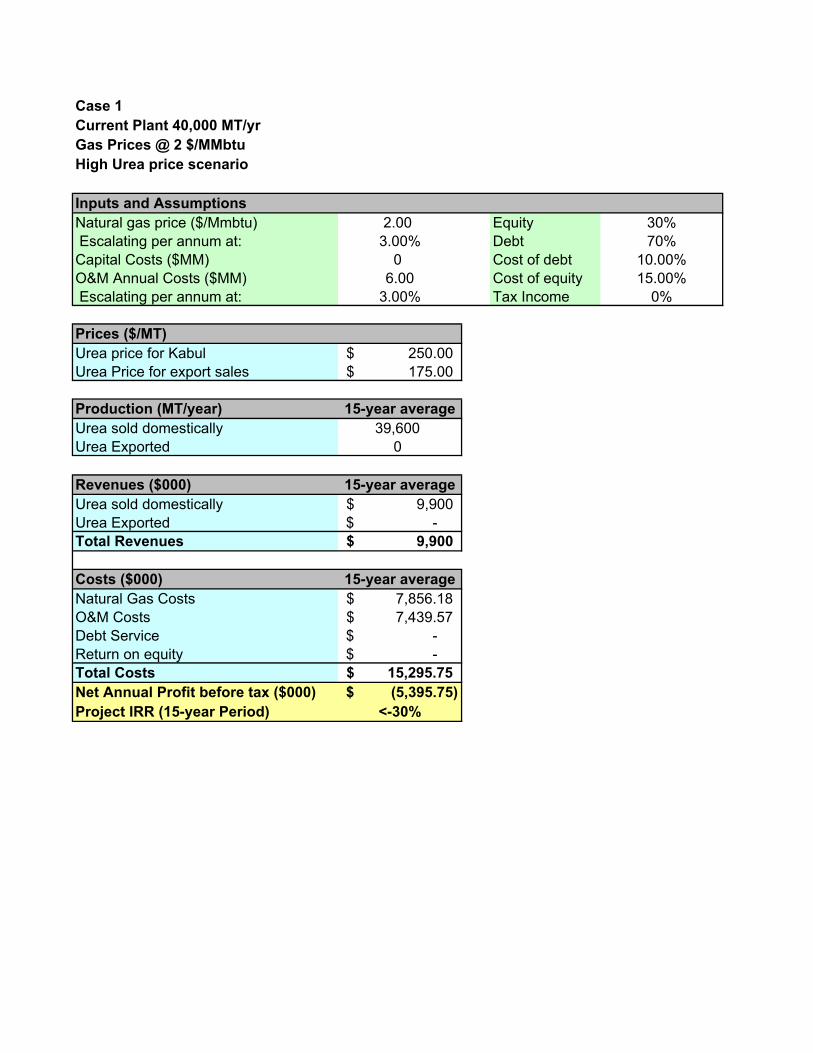
Case 1Current Plant 40,000 MT/yrGas Prices @ 2 $/MMbtuHigh Urea price scenario
Inputs and AssumptionsNatural gas price ($/Mmbtu) 2.00 Equity 30% Escalating per annum at: 3.00% Debt 70%Capital Costs ($MM) 0 Cost of debt 10.00%O&M Annual Costs ($MM) 6.00 Cost of equity 15.00% Escalating per annum at: 3.00% Tax Income 0%
Prices ($/MT)Urea price for Kabul 250.00$ Urea Price for export sales 175.00$
Production (MT/year) 15-year averageUrea sold domestically 39,600Urea Exported 0
Revenues ($000) 15-year averageUrea sold domestically 9,900$ Urea Exported -$ Total Revenues 9,900$
Costs ($000) 15-year averageNatural Gas Costs 7,856.18$ O&M Costs 7,439.57$ Debt Service -$ Return on equity -$ Total Costs 15,295.75$ Net Annual Profit before tax ($000) (5,395.75)$ Project IRR (15-year Period) <-30%

Case 1Current Plant 40,000 MT/yrGas Prices @ 4 $/MMbtuLow Urea price scenario
Inputs and AssumptionsNatural gas price ($/Mmbtu) 4.00 Equity 30% Escalating per annum at: 3.00% Debt 70%Capital Costs ($MM) 0 Cost of debt 10.00%O&M Annual Costs ($MM) 6.00 Cost of equity 15.00% Escalating per annum at: 3.00% Tax Income 0%
Prices ($/MT)Urea price for Kabul 200.00$ Urea Price for export sales 125.00$
Production (MT/year) 15-year averageUrea sold domestically 39,600Urea Exported 0
Revenues ($000) 15-year averageUrea sold domestically 7,920$ Urea Exported -$ Total Revenues 7,920$
Costs ($000) 15-year averageNatural Gas Costs 15,712.36$ O&M Costs 7,439.57$ Debt Service -$ Return on equity -$ Total Costs 23,151.93$ Net Annual Profit before tax ($000) (15,231.93)$ Project IRR (15-year Period) <-30%

Case 1Current Plant 40,000 MT/yrGas Prices @ 4 $/MMbtuHigh Urea price scenario
Inputs and AssumptionsNatural gas price ($/Mmbtu) 4.00 Equity 30% Escalating per annum at: 3.00% Debt 70%Capital Costs ($MM) 0 Cost of debt 10.00%O&M Annual Costs ($MM) 6.00 Cost of equity 15.00% Escalating per annum at: 3.00% Tax Income 0%
Prices ($/MT)Urea price for Kabul 250.00$ Urea Price for export sales 175.00$
Production (MT/year) 15-year averageUrea sold domestically 39,600Urea Exported 0
Revenues ($000) 15-year averageUrea sold domestically 9,900$ Urea Exported -$ Total Revenues 9,900$
Costs ($000) 15-year averageNatural Gas Costs 15,712.36$ O&M Costs 7,439.57$ Debt Service -$ Return on equity -$ Total Costs 23,151.93$ Net Annual Profit before tax ($000) (13,251.93)$ Project IRR (15-year Period) <-30%

Case 2Current Plant 100,000 MT/yrGas Prices @ 2 $/MMbtuLow Urea price scenario
Inputs and AssumptionsNatural gas price ($/Mmbtu) 2.00 Equity 30% Escalating per annum at: 3.00% Debt 70%Capital Costs ($MM) 40,000 Cost of debt 10.00%O&M Annual Costs ($MM) 9.00 Cost of equity 15.00% Escalating per annum at: 3.00% Tax Income 0%
Prices ($/MT)Urea price for Kabul 200.00$ Urea Price for export sales 125.00$
Production (MT/year) 15-year averageUrea sold domestically 94,500Urea Exported 0
Revenues ($000) 15-year averageUrea sold domestically 18,900$ Urea Exported -$ Total Revenues 18,900$
Costs ($000) 15-year averageNatural Gas Costs 10,545.58$ O&M Costs 11,159.35$ Debt Service 3,037.91$ Return on equity 1,800.00$ Total Costs 26,542.85$ Net Annual Profit before tax ($000) (7,642.85)$ Project IRR (15-year Period) <-30%

Case 2Current Plant 100,000 MT/yrGas Prices @ 2 $/MMbtuHigh Urea price scenario
Inputs and AssumptionsNatural gas price ($/Mmbtu) 2.00 Equity 30% Escalating per annum at: 3.00% Debt 70%Capital Costs ($MM) 40,000 Cost of debt 10.00%O&M Annual Costs ($MM) 9.00 Cost of equity 15.00% Escalating per annum at: 3.00% Tax Income 0%
Prices ($/MT)Urea price for Kabul 250.00$ Urea Price for export sales 175.00$
Production (MT/year) 15-year averageUrea sold domestically 94,500Urea Exported 0
Revenues ($000) 15-year averageUrea sold domestically 23,625$ Urea Exported -$ Total Revenues 23,625$
Costs ($000) 15-year averageNatural Gas Costs 10,545.58$ O&M Costs 11,159.35$ Debt Service 3,037.91$ Return on equity 1,800.00$ Total Costs 26,542.85$ Net Annual Profit before tax ($000) (2,917.85)$ Project IRR (15-year Period) <-30%

Case 2Current Plant 100,000 MT/yrGas Prices @ 4 $/MMbtuLow Urea price scenario
Inputs and AssumptionsNatural gas price ($/Mmbtu) 4.00 Equity 30% Escalating per annum at: 3.00% Debt 70%Capital Costs ($MM) 40,000 Cost of debt 10.00%O&M Annual Costs ($MM) 9.00 Cost of equity 15.00% Escalating per annum at: 3.00% Tax Income 0%
Prices ($/MT)Urea price for Kabul 200.00$ Urea Price for export sales 125.00$
Production (MT/year) 15-year averageUrea sold domestically 94,500Urea Exported 0
Revenues ($000) 15-year averageUrea sold domestically 18,900$ Urea Exported -$ Total Revenues 18,900$
Costs ($000) 15-year averageNatural Gas Costs 21,091.17$ O&M Costs 11,159.35$ Debt Service 3,037.91$ Return on equity 1,800.00$ Total Costs 37,088.43$ Net Annual Profit before tax ($000) (18,188.43)$ Project IRR (15-year Period) <-30%

Case 2Current Plant 100,000 MT/yrGas Prices @ 4 $/MMbtuHigh Urea price scenario
Inputs and AssumptionsNatural gas price ($/Mmbtu) 4.00 Equity 30% Escalating per annum at: 3.00% Debt 70%Capital Costs ($MM) 40,000 Cost of debt 10.00%O&M Annual Costs ($MM) 9.00 Cost of equity 15.00% Escalating per annum at: 3.00% Tax Income 0%
Prices ($/MT)Urea price for Kabul 250.00$ Urea Price for export sales 175.00$
Production (MT/year) 15-year averageUrea sold domestically 94,500Urea Exported 0
Revenues ($000) 15-year averageUrea sold domestically 23,625$ Urea Exported -$ Total Revenues 23,625$
Costs ($000) 15-year averageNatural Gas Costs 21,091.17$ O&M Costs 11,159.35$ Debt Service 3,037.91$ Return on equity 1,800.00$ Total Costs 37,088.43$ Net Annual Profit before tax ($000) (13,463.43)$ Project IRR (15-year Period) <-30%

Case 3New Plant 100,000 MT/yrGas Prices @ 2 $/MMbtuLow Urea price scenario
Inputs and AssumptionsNatural gas price ($/Mmbtu) 2.00 Equity 30% Escalating per annum at: 3.00% Debt 70%Capital Costs ($MM) 88,157 Cost of debt 10.00%O&M Annual Costs ($MM) 7.05 Cost of equity 15.00% Escalating per annum at: 3.00% Tax Income 0%
Prices ($/MT)Urea price for Kabul 200.00$ Urea Price for export sales 125.00$
Production (MT/year) 15-year averageUrea sold domestically 90,000Urea Exported 0
Revenues ($000) 15-year averageUrea sold domestically 18,000$ Urea Exported -$ Total Revenues 18,000$
Costs ($000) 15-year averageNatural Gas Costs 6,026.05$ O&M Costs 8,744.63$ Debt Service 6,695.31$ Return on equity 3,967.05$ Total Costs 25,433.04$ Net Annual Profit before tax ($000) (7,433.04)$ Project IRR (15-year Period) -9.4%

Case 3New Plant 100,000 MT/yrGas Prices @ 2 $/MMbtuHigh Urea price scenario
Inputs and AssumptionsNatural gas price ($/Mmbtu) 2.00 Equity 30% Escalating per annum at: 3.00% Debt 70%Capital Costs ($MM) 88,157 Cost of debt 10.00%O&M Annual Costs ($MM) 7.05 Cost of equity 15.00% Escalating per annum at: 3.00% Tax Income 0%
Prices ($/MT)Urea price for Kabul 250.00$ Urea Price for export sales 175.00$
Production (MT/year) 15-year averageUrea sold domestically 90,000Urea Exported 0
Revenues ($000) 15-year averageUrea sold domestically 22,500$ Urea Exported -$ Total Revenues 22,500$
Costs ($000) 15-year averageNatural Gas Costs 6,026.05$ O&M Costs 8,744.63$ Debt Service 6,695.31$ Return on equity 3,967.05$ Total Costs 25,433.04$ Net Annual Profit before tax ($000) (2,933.04)$ Project IRR (15-year Period) 4.2%

Case 3New Plant 100,000 MT/yrGas Prices @ 4 $/MMbtuLow Urea price scenario
Inputs and AssumptionsNatural gas price ($/Mmbtu) 4.00 Equity 30% Escalating per annum at: 3.00% Debt 70%Capital Costs ($MM) 88,157 Cost of debt 10.00%O&M Annual Costs ($MM) 7.05 Cost of equity 15.00% Escalating per annum at: 3.00% Tax Income 0%
Prices ($/MT)Urea price for Kabul 200.00$ Urea Price for export sales 125.00$
Production (MT/year) 15-year averageUrea sold domestically 90,000Urea Exported 0
Revenues ($000) 15-year averageUrea sold domestically 18,000$ Urea Exported -$ Total Revenues 18,000$
Costs ($000) 15-year averageNatural Gas Costs 12,052.10$ O&M Costs 8,744.63$ Debt Service 6,695.31$ Return on equity 3,967.05$ Total Costs 31,459.09$ Net Annual Profit before tax ($000) (13,459.09)$ Project IRR (15-year Period) <-30%

Case 3New Plant 100,000 MT/yrGas Prices @ 4 $/MMbtuHigh Urea price scenario
Inputs and AssumptionsNatural gas price ($/Mmbtu) 4.00 Equity 30% Escalating per annum at: 3.00% Debt 70%Capital Costs ($MM) 88,157 Cost of debt 10.00%O&M Annual Costs ($MM) 7.05 Cost of equity 15.00% Escalating per annum at: 3.00% Tax Income 0%
Prices ($/MT)Urea price for Kabul 250.00$ Urea Price for export sales 175.00$
Production (MT/year) 15-year averageUrea sold domestically 90,000Urea Exported 0
Revenues ($000) 15-year averageUrea sold domestically 22,500$ Urea Exported -$ Total Revenues 22,500$
Costs ($000) 15-year averageNatural Gas Costs 12,052.10$ O&M Costs 8,744.63$ Debt Service 6,695.31$ Return on equity 3,967.05$ Total Costs 31,459.09$ Net Annual Profit before tax ($000) (8,959.09)$ Project IRR (15-year Period) <-30%

Case 4New Plant 300,000 MT/yrGas Prices @ 2 $/MMbtuLow Urea price scenario
Inputs and AssumptionsNatural gas price ($/Mmbtu) 2.00 Equity 30% Escalating per annum at: 3.00% Debt 70%Capital Costs ($MM) 229,919 Cost of debt 10.00%O&M Annual Costs ($MM) 18.39 Cost of equity 15.00% Escalating per annum at: 3.00% Tax Income 0%
Prices ($/MT)Urea price for Kabul 200.00$ Urea Price for export sales 125.00$
Production (MT/year) 15-year averageUrea sold domestically 231,470Urea Exported 38,530
Revenues ($000) 15-year averageUrea sold domestically 46,294$ Urea Exported 4,816$ Total Revenues 51,110$
Costs ($000) 15-year averageNatural Gas Costs 14,062.56$ O&M Costs 22,806.65$ Debt Service 17,461.87$ Return on equity 10,346.36$ Total Costs 64,677.44$ Net Annual Profit before tax ($000) (13,567.18)$ Project IRR (15-year Period) -1.1%

Case 4New Plant 300,000 MT/yrGas Prices @ 2 $/MMbtuHigh Urea price scenario
Inputs and AssumptionsNatural gas price ($/Mmbtu) 2.00 Equity 30% Escalating per annum at: 3.00% Debt 70%Capital Costs ($MM) 229,919 Cost of debt 10.00%O&M Annual Costs ($MM) 18.39 Cost of equity 15.00% Escalating per annum at: 3.00% Tax Income 0%
Prices ($/MT)Urea price for Kabul 250.00$ Urea Price for export sales 175.00$
Production (MT/year) 15-year averageUrea sold domestically 231,470Urea Exported 38,530
Revenues ($000) 15-year averageUrea sold domestically 57,868$ Urea Exported 6,743$ Total Revenues 64,610$
Costs ($000) 15-year averageNatural Gas Costs 14,062.56$ O&M Costs 22,806.65$ Debt Service 17,461.87$ Return on equity 10,346.36$ Total Costs 64,677.44$ Net Annual Profit before tax ($000) (67.18)$ Project IRR (15-year Period) 9.4%

Case 4New Plant 300,000 MT/yrGas Prices @ 4 $/MMbtuLow Urea price scenario
Inputs and AssumptionsNatural gas price ($/Mmbtu) 4.00 Equity 30% Escalating per annum at: 3.00% Debt 70%Capital Costs ($MM) 229,919 Cost of debt 10.00%O&M Annual Costs ($MM) 18.39 Cost of equity 15.00% Escalating per annum at: 3.00% Tax Income 0%
Prices ($/MT)Urea price for Kabul 200.00$ Urea Price for export sales 125.00$
Production (MT/year) 15-year averageUrea sold domestically 231,470Urea Exported 38,530
Revenues ($000) 15-year averageUrea sold domestically 46,294$ Urea Exported 4,816$ Total Revenues 51,110$
Costs ($000) 15-year averageNatural Gas Costs 28,125.11$ O&M Costs 22,806.65$ Debt Service 17,461.87$ Return on equity 10,346.36$ Total Costs 78,739.99$ Net Annual Profit before tax ($000) (27,629.73)$ Project IRR (15-year Period) <-30%

Case 4New Plant 300,000 MT/yrGas Prices @ 4 $/MMbtuHigh Urea price scenario
Inputs and AssumptionsNatural gas price ($/Mmbtu) 4.00 Equity 30% Escalating per annum at: 3.00% Debt 70%Capital Costs ($MM) 229,919 Cost of debt 10.00%O&M Annual Costs ($MM) 18.39 Cost of equity 15.00% Escalating per annum at: 3.00% Tax Income 0%
Prices ($/MT)Urea price for Kabul 250.00$ Urea Price for export sales 175.00$
Production (MT/year) 15-year averageUrea sold domestically 231,470Urea Exported 38,530
Revenues ($000) 15-year averageUrea sold domestically 57,868$ Urea Exported 6,743$ Total Revenues 64,610$
Costs ($000) 15-year averageNatural Gas Costs 28,125.11$ O&M Costs 22,806.65$ Debt Service 17,461.87$ Return on equity 10,346.36$ Total Costs 78,739.99$ Net Annual Profit before tax ($000) (14,129.73)$ Project IRR (15-year Period) -2.0%

HILL INTERNATIONAL, INC. AFG/0361/TF 030397 EVALUATION OF INVESTMENT OPTIONS FOR THE DEVELOPMENT PROJECT NO. PAG238/R. BORHAN/ AUGUST 15, 2004 OF OIL AND GAS INFRASTRUCTURE IN AFGHANISTAN TASK 1B: REHABILITATION OF GAS PROCESSING AND FERTILIZER FACILITIES
PAGE 126
4.10 Staffing and Training
A subject which is of concern whenever the subject of shutting the whole or part of the fertilizer plant comes up is the social issues of employment. This is indeed a very sensitive issue in the present political and economic context of Afghanistan.
The Fertilizer plant was built between 1967 and 1974. Most of the non-supervisory technical staff was hired at that time, presumably as unskilled or semi-skilled labor and trained by Soviet supervisors to take up skilled positions as they gained seniority. Most of the employees seen at the plant are in their fifties and are getting close to their retirement age, which are 60. Even most of the engineers in supervisory positions were hired in the early seventies. Going through the plants, it is rare to see any young people. If a decision is taken to shut down and dismantle the fertilizer plant while retaining and rehabilitating the power plant, a thorough manpower inventory should be undertaken to decide on retirement, retraining or retention of employees. Even those employees selected for retrenchment may be utilized in the dismantling phase of the plant and the early period of construction of the new plant.
During our visits to the plant, the limited assessment that could be made during plant visits and discussions did not give much confidence in the staff’s technical or intellectual ability. Since they joined Kud Bergh, the only plant they have been exposed to is the outdated technology brought to Afghanistan by the Soviets. Those few who had the chance to travel visited to a country in the FSU with equally outdated technology and poor management methods. During the five visits made to the site by the Consultant, not a single person was observed wearing any safety gear (hard hats, safety shoes). Employees in operating areas were seen wearing sandals, and smoking in operating areas even by Engineers was observed on many occasions. Retraining these employees in their fifties to learn and run a modern plant is not a promising option.
This is especially true when moving to a new plant with tighter design and operating tolerances. Setting aside the economics, if a new or reconditioned plant replaces the existing fertilizer plant, a very careful plan will have to be developed to recruit and train a group of about 50 engineers of the highest caliber. The training will have to be done at a modern plant of similar design with a combination of classroom, field and supervisory training. They should then be brought to the plant during its installation phase and under competent professionals, the training should continue. A similar, lower level technical program should be started for about 150 high school graduates starting with at least 1-2 years rigorous training in English, Mathematics and Sciences, followed by one to two years training in an operating plant of similar design. Some mechanical technicians from the existing plant who have good skills and attitude should be picked up for refresher training and then become trainers for new technical school graduates to number another 150. This group under an initial group of 30-50 expatriate professionals from neighboring countries that have well-established fertilizer plants should be sufficient to run the plant for the first 2-3 years. The number of the expatriate staff can be gradually reduced as the Afghan employees become skilled both technically and in supervisory skills.

HILL INTERNATIONAL, INC. AFG/0361/TF 030397 EVALUATION OF INVESTMENT OPTIONS FOR THE DEVELOPMENT PROJECT NO. PAG238/R. BORHAN/ AUGUST 15, 2004 OF OIL AND GAS INFRASTRUCTURE IN AFGHANISTAN TASK 1B: REHABILITATION OF GAS PROCESSING AND FERTILIZER FACILITIES
PAGE 127
A preliminary program for training the above cadre of employees is presented and costed below:
Table 4-D: Representative Training Course for Fertilizer Plant Senior and Junior Plant Managers and Technicians
Senior Personnel Number of Trainees
Training Man-Days
Cost per Training Unit
Total
Out-of-country Training Course (onsite)
25 750 $ 550 $ 412,500
In-Country Training (3 expat instructors)
50 180 $ 1,200 $ 216,000
Junior Personnel
Out-of-country Training Course (onsite)
25 700 $ 550 $ 385,000
In-Country Training 50 180 $ 1,000 $ 180,000
Miscellaneous Expenses @ 10%
$ 119,350
Total:
$ 1,312,850
Notes:
1. Offsite Training assumed to be in India (ONGC quotes)
2. Assumes trainees becoming trainers for other staff

HILL INTERNATIONAL, INC. AFG/0361/TF 030397 EVALUATION OF INVESTMENT OPTIONS FOR THE DEVELOPMENT PROJECT NO. PAG238/R. BORHAN/ AUGUST 15, 2004 OF OIL AND GAS INFRASTRUCTURE IN AFGHANISTAN TASK 1B: REHABILITATION OF GAS PROCESSING AND FERTILIZER FACILITIES
PAGE 128
For a new Gas Processing Plant, a proposed training program is costed below. We would suggest that should rehabilitation of the existing plant be undertaken, that a reduced training program for plant personnel at about 30% level of training of the new plant shown below, or approximately $250,000 be adopted so that new and existing staff can get exposed to new technologies, as well as be trained on
Table 4-E: Representative Training Course for Gas Processing Plant Senior and Junior Plant Managers and Technicians
Senior Personnel Number of Trainees
Training Man-Days
Cost per Training Unit
Total
Out-of-country Training Course (onsite)
10 300 $ 550 $ 165,000
In-Country Training (3 expat instructors)
25 180 $ 1,200 $ 216,000
Junior Personnel
Out-of-country Training Course (onsite)
20 280 $ 550 $ 154,000
In-Country Training 40 180 $ 1,000 $ 180,000
Miscellaneous Expenses @ 10%
$ 71,500
Total:
$ 786,500
Notes:
1. Offsite Training assumed to be in India (ONGC quotes)
2. Assumes trainees becoming trainers for other staff

HILL INTERNATIONAL, INC. AFG/0361/TF 030397 EVALUATION OF INVESTMENT OPTIONS FOR THE DEVELOPMENT PROJECT NO. PAG238/R. BORHAN/ AUGUST 15, 2004 OF OIL AND GAS INFRASTRUCTURE IN AFGHANISTAN TASK 1B: REHABILITATION OF GAS PROCESSING AND FERTILIZER FACILITIES
PAGE 129
5.0 Power Plant at Kud Bergh
5.1 Current Technical and Operational Condition
5.1.1 Overall Plant Condition
The Power Plant was built at the same time as the Fertilizer Plant during the 1967-74 periods, mainly to provide power to the large number of compressors and pumps that the old design Fertilizer Plant employs. It has a rated capacity to generate 48 MW of power from four turbine generators of 12 MW each. The steam for the turbines is supplied by five water tube boilers run on gas.
The Power Plant consists of 5 boilers for steam generation which are designed to produce 75 Tons/hr each of superheated steam at 39 atms. pressure and 440 deg. C temperature. The steam is supplied to the four turbines, designed to take the steam at 35 atms. pressure and 435 deg. C temperature. Each turbine is designed to produce 12 MW of power. Currently, due to shortage of gas and low power demand in the Fertilizer Plant, only three boilers are being operated, producing 45-50 Tons per hour of steam. Also, only three turbine generators are operating, generating 18MW of power. Of this, 16 MW is used in the Fertilizer Plant and the balance is being supplied to the factory housing. There is also an emergency power facility consisting of two diesel-driven 500 KW generator units, of which one is out of service due to lack of spare parts.
5.1.2 Plant Inspection Report
The summary inspection report of the Power Plant at Kud Bergh is presented in this section.
HILL INTERNATIONAL, INC. AFG/0361/TF 030397 EVALUATION OF INVESTMENT OPTIONS FOR THE DEVELOPMENT PROJECT NO. PAG238/R. BORHAN/ AUGUST 15, 2004 OF OIL AND GAS INFRASTRUCTURE IN AFGHANISTAN TASK 1B: REHABILITATION OF GAS PROCESSING AND FERTILIZER FACILITIES
PAGE 130
SUMMARY INSPECTION REPORT OF ELECTRIC POWER HOUSE NEAR MAZARSHARIF
Plant Detail
Location of plant 30 km, from Mazar-E-Sharif Plant commissioned 1974
Details of Major Equipment and Machinery
Steam Boiler
Total Steam Boiler 5 Nos. Steam Generation Capacity 75 Tons /Hr each boiler. Operating Steam Pressure 40 kg/cm² Superheated Steam Temperature 440 °C
Classification
Water Tube Induced draft fan with Electric Motor Driver for flue gas exhaust, 200 KW, 25.5 A 6 KV 590 RPM. Forced draft fan with Electric Motor Driver for fresh air circulation, 180 KW, 23.5 Amp, 6 KV, 750 RPM. Boiler feed water Heater Six gas fired burners Boiler tube diameter 57 mm Economizer tube diameter 32 mm Manufacturing date of Boiler 1973
Steam Turbine and Electric Generator
Total Turbine Generators 4 Nos. Design Capacity 4x12 = 48 MW Generating voltage 6 KV Inlet steam pressure 35 ATMS 1st Extraction of Steam 10 ATMS, 50 Tons Hour 2nd Extraction of Steam 1.2 ATMS, 40 Tons Hour Rotating Speed of Turbo Generator 3000 RPM

HILL INTERNATIONAL, INC. AFG/0361/TF 030397 EVALUATION OF INVESTMENT OPTIONS FOR THE DEVELOPMENT PROJECT NO. PAG238/R. BORHAN/ AUGUST 15, 2004 OF OIL AND GAS INFRASTRUCTURE IN AFGHANISTAN TASK 1B: REHABILITATION OF GAS PROCESSING AND FERTILIZER FACILITIES
PAGE 131
Condition of Equipment and Machinery
Boiler # 1
Boiler was in operation. 30% boiler tubes are plugged due to leakage. Economizer tubes (preheating of feed water) also partially plugged. Boiler was operating below capacity and efficiency due to poor condition of tubes.
Boiler # 2
Boiler was in operation. 30% boiler tubes are plugged. Economizer tubes are also partially plugged, boiler operating below capacity and efficiency.
Boiler # 3
Boiler was not operating 30% tubes are plugged. Boiler was shutdown due to less steam requirement.
Boiler # 4
Boiler has not been in operation for the last ten years. 80% of the tubes are plugged. Internal Inspection including thickness and Hardness measurements were carried out and are tabulated at the end of this report.
Boiler # 5
Boiler was in operation. 50% of the tubes are plugged.
Boilers Overall
The condition of the boilers is not satisfactory due to the poor condition of tubes. More than 50% of the tubes (average) are plugged in both the radiant and connection section of boiler.
The condition of electric motors and fan were normal.
Manuals, drawings were not available.
Thickness measurements of boiler tubes and surface hardness was checked and tabulated
Surface vibration readings of fan and electric motors bearings were noted and tabulated
Turbine Generators
Three generators were running on loads varying from 3 MW to 7 MW against a rated load of 12 MW. One generator was out of service due to the damaged winding of the exciter. The surface vibration was recorded on all three generators at 6 bearing locations. Noise level was also measured. The vibration level was at a higher range as compared to the normal range recommended for turbo generators. Generator # 4

HILL INTERNATIONAL, INC. AFG/0361/TF 030397 EVALUATION OF INVESTMENT OPTIONS FOR THE DEVELOPMENT PROJECT NO. PAG238/R. BORHAN/ AUGUST 15, 2004 OF OIL AND GAS INFRASTRUCTURE IN AFGHANISTAN TASK 1B: REHABILITATION OF GAS PROCESSING AND FERTILIZER FACILITIES
PAGE 132
was having excessive surface vibration at the turbine exhaust end bearing and corresponding generating bearing. As per operating staff the machine vibration increases when electrical load is increased on generator.
No manuals or drawings were available.

Annex 5.1.2-1
Legend H = Horizontal
V = Vertical
A = Axial
POWER PLANT AT KUD BERGH
LocationRef. Point Reading Range in/sec Ref. Point Location Reading Range in/sec
Vibration Inspection Report of Turbo Generator Unit No. 01
Ref. Point Location Reading Range in/sec
Sketch of Turbo Generator
A 0.103 ~ 0.105
1 V
H
0.105 ~ 0.105
0.099 ~ 0.104
Ref. Point Location Reading Range in/sec
0.040 ~ 0.040
2
H 0.085 ~ 0.085
V 0.003 ~ 0.005
A
3
H 0.192 ~ 0.194
V 0.119 ~ 0.118
A 0.015 ~ 0.019
Ref. Point Location Reading Range in/sec
4
H 0.028 ~ 0.041
V 0.038 ~ 0.042
A 0.010 ~ 0.014
Ref. Point Location Reading Range in/sec
5
H 0.011 ~ 0.014
V 0.018 ~ 0.024
A 0.028 ~ 0.028
6
H 0.033 ~ 0.028
V 0.029 ~ 0.033
A 0.050 ~ 0.048
Steam
654321
Generator Excitor

Annex 5.1.2-1
Legend H = Horizontal
V = Vertical
A = Axial
6
H 0.088 ~ 0.090
V 0.034 ~ 0.046
A 0.074 ~ 0.084
Ref. Point
5
A
Location Reading Range in/sec
Location Reading Range in/sec
H 0.072 ~ 0.077
V 0.039 ~ 0.058
Ref. Point
4
H 0.043 ~ 0.057
V 0.042 ~ 0.077
A 0.183 ~ 0.187
0.049 ~ 0.054
Ref. Point
3
H 0.063 ~ 0.075
V 0.061 ~ 0.067
A 0.087 ~ 0.097
0.027 ~ 0.046
0.071 ~ 0.076
Location Reading Range in/sec
0.025 ~ 0.037
A 0.052 ~ 0.056
Location Reading Range in/secRef. Point
1 V
H
2
H 0.041 ~ 0.047
V 0.049 ~ 0.051
A
POWER PLANT AT KUD BERGH
LocationRef. Point Reading Range in/sec Ref. Point Location Reading Range in/sec
Vibration Inspection Report of Turbo Generator Unit No. 03
Sketch of Turbo Generator
Steam Turbine
654321
Generator Excitor

Annex 5.1.2-1
Legend H = Horizontal
V = Vertical
A = Axial
POWER PLANT AT KUD BERGH
LocationRef. Point Reading Range in/sec Ref. Point Location Reading Range in/sec
Vibration Inspection Report of Turbo Generator Unit No. 04
Location Reading Range in/sec
0.219 ~ 0.234
Sketch of Turbo Generator
Ref. Point
4
H 0.086 ~ 0.094
V
A
1 V
H
0.027 ~ 0.034
0.331 ~ 0.335
Ref. Point Location Reading Range in/sec
0.141 ~ 0.146
2
H 0.227 ~ 0.233
V 0.139 ~ 0.142
A
3
H 0.258 ~ 0.263
V 0.126 ~ 0.125
A 0.115 ~ 0130
0.126 ~ 0.122
A 0.283 ~ 0.289
Location Reading Range in/sec
0.050 ~ 0.051
5
H 0.006 ~ 0.009
V 0.120 ~ 0.126
A 0.034 ~ 0.040
Ref. Point
6
H 0.060 ~ 0.062
Ref. Point Location Reading Range in/sec
V 0.041 ~ 0.075
A
Steam Turbine
654321
Generator Excitor

Annex 5.1.2-1
Legend H = Horizontal
V = Vertical
A = Axial
Fan Side Bearing
H 0.080 ~ 0.085
V 0.050 ~ 0.054
A 0.033 ~ 0.035
Motor Side Bearing
H 0.048 ~ 0.052
V 0.044 ~ 0.047
A 0.063 ~ 0.067
0.010 ~ 0.013
Motor Side Bearing
Ref. Point Location Reading Range in/sec Ref. Point Location Reading Range in/sec
V 0.025 ~ 0.028
Ref. Point Location Reading Range in/sec
Vibration Inspection Report of Fan and Motor of Boiler No. 01
Fan Side Bearing
H 0.021~ 0.025
V 0.05 ~ 0.055
AA -
Ref. Point Location Reading Range in/sec
H 0.022 ~ 0.027
Vibration Inspection Report of Fan and Motor of Boiler No. 02
0.100 ~ 0.108
0.075 ~ 0.082
A 0.096 ~ 0.092 A 0.069 ~ 0.074
Fan Side Bearing
HMotor Side
Bearing V
H
0.031 ~ 0.029
Ref. Point Reading Range in/sec
POWER PLANT AT KUD BERGH
Sketch of Fan and Motor
Vibration Inspection Report of Fan and Motor of Boiler No. 05Location Reading Range in/secLocation Ref. Point
0.017 ~ 0.015
V
Fan Motor

Annex 5.1.2-2
POWER PLANT
Internal Inspection Report of Boiler No. 04 with Thickness and Hardness Measurement − Minimum Tube Thickness 4.4 mm, Hardness 317 HB
− Maximum Tube Thickness 5.2 mm, Hardness 298 HB
− North side total Tube 35 Nos., damaged 24 Nos.
− South side total Tube 53 Nos., damaged 24 Nos.
− East side total Tube 49 Nos., damaged 11 Nos.
− West side total Tube 51 Nos., damaged 11 Nos.
− Internal Temperature 49 °C ~ 50 °C
North South
East
West
Manhole
Manhole
N S
W
E
Tube Refractory

Damaged Exciter of Generator
POWER PLANT
Ducting of Boiler
Damaged Motors
Power Generator

Forced Draft Fan Motor of Boiler
Economizer Tubes of Boiler No. 4
Economizer Tubes of Boiler No. 4
Economizer Tubes of Boiler No. 4
POWER PLANT
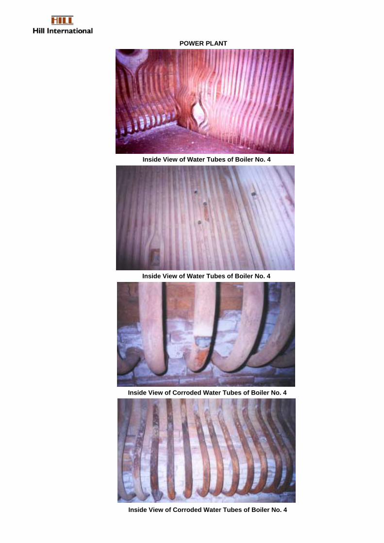
Inside View of Water Tubes of Boiler No. 4
Inside View of Water Tubes of Boiler No. 4
Inside View of Corroded Water Tubes of Boiler No. 4
Inside View of Corroded Water Tubes of Boiler No. 4
POWER PLANT

Inside View of Water Tubes of Boiler No. 4
Gas Fire Burners of Boiler No. 4
Inside View of Water Tubes of Boiler No. 4
Gas Fire Burner of Boiler No. 4
POWER PLANT

Manhole of Boiler No. 4
Super Heater of Boiler No. 4
Ducting of Forced Draft Fan of Boiler No. 4
Forced Draft Fan of Boiler No. 4
POWER PLANT

HILL INTERNATIONAL, INC. AFG/0361/TF 030397 EVALUATION OF INVESTMENT OPTIONS FOR THE DEVELOPMENT PROJECT NO. PAG238/R. BORHAN/ AUGUST 15, 2004 OF OIL AND GAS INFRASTRUCTURE IN AFGHANISTAN TASK 1B: REHABILITATION OF GAS PROCESSING AND FERTILIZER FACILITIES
PAGE 143
5.1.3 Summary of Findings
The old age of the plant and the break-up of the Soviet Union make the supply of spare parts for the efficient operation of the plant very difficult. If an adequate supply of gas were available, lack of spare parts would have become a critical issue. However, due to large number of identical equipment installed in parallel, there is always a tendency to cannibalize the idle equipment to run the plant at partial load.
According to Plant Management, some spares are being procured through a number of Trading Companies who are provided the specifications of the spares through the Ministry of Mines and Industry in Kabul. This is surely not the ideal way, but perhaps the only way, that the critical spares can be procured.
Observations
• The condition of the boilers is not satisfactory due to the poor condition of the wall tubes. 50% of the tubes, on the average, are plugged, in both radiant and connection sections of the boilers. Of the tubes in service, many have repair patches welded on to them (a very unsafe practice). It was reported by the Power Plant supervisors that the condition of the other four boilers is no better
• The condition of the electric motors and fan was normal.
• Manuals and drawings were not available.
• Thickness measurements of the boiler tubes and their surface hardness were checked and are tabulated.
• Surface vibration readings of fan and electric motors bearings were noted and are tabulated.
• Steam boilers should be revamped by retubing. This will increase steam Production and increase generation capacity.
• Turbo generators should be overhauled for generation of rated capacity.
The general condition of other auxiliary areas of the boilers is also not satisfactory. Refractory and insulation are in poor condition and require major repairs and replacement. Cleaning and inspection of steam-drums and mud-drums also needs to be carried out. The instruments are obsolete and mostly uncalibrated for a long time and many are non-functional. The boilers employ a combination of induced and forced –draft fans that require thorough inspection and servicing. However, no major replacement of any components of these appears to be necessary.
The turbine generators are also in a poor state of maintenance. However, whereas the poor condition of the boilers seems to be the result of lack of funds and poor standards of workmanship, the turbines have likely suffered due to the failure of the plant management to procure critical spare parts. Like elsewhere in Kud Bergh, there are no manuals and drawings available to help in the procurement of spares.
Currently, three of the four turbo generators are running with varied loads, generating a total of 18 MW of power. Turbo generator #2 is out of service due to lack of spare

HILL INTERNATIONAL, INC. AFG/0361/TF 030397 EVALUATION OF INVESTMENT OPTIONS FOR THE DEVELOPMENT PROJECT NO. PAG238/R. BORHAN/ AUGUST 15, 2004 OF OIL AND GAS INFRASTRUCTURE IN AFGHANISTAN TASK 1B: REHABILITATION OF GAS PROCESSING AND FERTILIZER FACILITIES
PAGE 144
parts. It appeared that the shut-down unit has been cannibalized to keep the other units running. The condition of the operating turbo generator units is also not very satisfactory. Turbo generator unit #4 has high vibrations and its generation is restricted to about 4.5 MW. The cause of the high vibration was given as US bombing in the area in late 2001. The other two turbo generators are also running at reduced load due to low power demand from the Fertilizer Plant.
5.2 Options for Rehabilitation or Replacement
The prospects of rehabilitating the Power Plant are considered reasonably good, as the boilers and the turbine generators which would need to be rehabilitated or replaced are standard items of equipment that should not face spares availability problems. However it should be noted that 100% rated capacity will likely never be reached. Furthermore, any consideration for rehabilitation should be addressed as part of the power sector master plan. Hence in light of the proposed 150 MW gas power plant to be built at Sherberghan under the master power plan, a full rehabilitation or replacement of this plant is not prudent. Rather it would be recommended that the plant be kept running for the next 2-3 years (with minimal investment of about $2-3 million) for absolutely necessary spare parts and equipment ) and then decommission the plant once the 150 MW gas power plant is built in Sherberghan.
For indicative purpose only, the consultant has provided some analysis in the following paragraphs, for the likely costs for rehabilitating such a plant.The rehabilitation of the boilers is a fairly straightforward exercise. It requires 100% tube replacement, which can be undertaken by any engineering/fabrication company, ideally from the FSU or neighboring countries. Boiler tubes are standard items that can be procured easily from any number of countries that meet the standard specifications. It is likely that the Taganrog Boiler Factory in Russia, one of the major boiler suppliers in the FSU, will be able to provide tubing and installation, erection and testing services. All other works related to boilers can be carried out without any difficulty. While the rehabilitation works are going on, a good instrumentation firm can be contracted to design and install new instrumentation system to meet modern standards.
An estimate of costs for the rehabilitation of the boilers is presented following this section.
Rehabilitating the turbine generators may require a little more ingenuity and investigative work. Since these are standard power generation machinery items, it is expected that several countries in the FSU would have been producing them. Initially, five countries, Russia, Poland, Czech Republic, Ukraine and China should be explored to confirm that they have designs and facilities to supply rotors, couplings, bearings and seals etc, for these machines. It is likely that either the Leningradskiy Metallicheskiy Zaovd (LMZ) or ElectroSila, both in St. Petersburg, supplied the equipment (and can indicate who did) and should be contacted first.

HILL INTERNATIONAL, INC. AFG/0361/TF 030397 EVALUATION OF INVESTMENT OPTIONS FOR THE DEVELOPMENT PROJECT NO. PAG238/R. BORHAN/ AUGUST 15, 2004 OF OIL AND GAS INFRASTRUCTURE IN AFGHANISTAN TASK 1B: REHABILITATION OF GAS PROCESSING AND FERTILIZER FACILITIES
PAGE 145
Another approach that can be taken is to entrust the entire task for servicing and rehabilitation to one of several specialized companies engaged in this type of work. Siemens, ABB, Woods Group, or SevzapEnergoMontazh are several contractors who have FSU experience in power plants. The first three companies have offices in Dubai, and SZEM is located in St. Petersburg, and all can be contacted to send their specialists to visit the plant and provide a detailed estimate for the works.
One of the two emergency diesel-generators is out of service because some critical spares cannot be procured in spite of all efforts. These generators provide 500 KW power each and are used when gas supplies are interrupted and emergency power is needed to run critical services and to restart the plant. The generator also supplies power to the Factory Housing. The supervisor in charge of the unit was unable to get information about the original manufacturers or any other source of spares. All his efforts to procure the spares even through the trading companies have been unsuccessful. It is suggested that remnants of the Soviet energy clearing house system be initially contacted for this equipment and for all other spares as well.
In addition to replacing the defective and worn out components of the four turbine generators, a thorough check of the foundations of the machines should also be undertaken. It may be necessary to design and pour new foundations in case the old foundations have been damaged or weakened due to bombings or earthquakes in the area during the last 25 years. In any case the foundations are 30-35 years old, and when major expenditure is being made for rehabilitation, this will be a small component of the total cost.
An estimate of the work involved in the rehabilitation of the turbine generators is presented at the end of this section.

HILL INTERNATIONAL, INC. AFG/0361/TF 030397 EVALUATION OF INVESTMENT OPTIONS FOR THE DEVELOPMENT PROJECT NO. PAG238/R. BORHAN/ AUGUST 15, 2004 OF OIL AND GAS INFRASTRUCTURE IN AFGHANISTAN TASK 1B: REHABILITATION OF GAS PROCESSING AND FERTILIZER FACILITIES
PAGE 146
Cost Estimate for Rehabilitation of 5 Boilers
1. Tube Replacement Materials
Number of tubes in each boiler
188 in radiant section+ 52 (est. in economizer)
Total number of tubes to be replaced in 5 boilers 1,200 Length of each tube 14.1 m. Total quantity of tubes required 1,200X14.1 = 16,920 m. Allowing for 20% wastage, total quantity required 16,920X1.2 = 20,300 m. Cost of tubes @ $50.00 per meter at site $1,015,000 Consumables, Tools, Other materials @ 20% $203,000 Labor
18 technicians for 30 working days for: Cutting, Bending, Refitting & Welding 540 man days Direct labor cost 540X$800 per man day $432,000
Supervision, Inspection (100% dye-penetrant test, 10% radiography) 30% of direct labor cost $129,600 Travel, Accommodation at site, Food, Local Travel 30% of labor $168,480 Total Labour & Material Costs of Tube Replacement $1,948,080 2. Steam & Mud Drum Cleaning Total number of drums to be cleaned 10 Labor: 10 man days per drum, total man days, 10x 10 = 100 100 Labor cost @ $800 per day $80,000 Supervision, Inspection @ 30% $24,000 Travel, Accommodation at site, Food, Local Travel 30% of labor $31,200 Materials, Consumables, Tools etc. $10,000 Total Material & Labor Costs of Steam & Mud Drum Cleaning $145,200
3.Servicing & Reliability Improvement of Forced & Induced Draft Fans
The work covers the inspection, servicing and repairs to Fans, Motors, Bearings, Couplings, Duct Work & Foundations. Spare Parts, Consumables, Tools etc. @$20,000 per boiler $100,000 Labor, 50 man days per boiler, total 250 man days @ $800 per man-day $200,000 Supervision, Inspection (much more supervision involvement) @ 50% $100,000

HILL INTERNATIONAL, INC. AFG/0361/TF 030397 EVALUATION OF INVESTMENT OPTIONS FOR THE DEVELOPMENT PROJECT NO. PAG238/R. BORHAN/ AUGUST 15, 2004 OF OIL AND GAS INFRASTRUCTURE IN AFGHANISTAN TASK 1B: REHABILITATION OF GAS PROCESSING AND FERTILIZER FACILITIES
PAGE 147
Travel, Accommodation at site, Food, Local Travel 30% of labor $90,000 Total Material & Labor Costs for servicing Forced & ID Fans $490,000
4.Rehabilitation of Control Room and Cost of Modern Electronic Control Systems
This is a very specialized job and at this stage a rough estimate can be made. In order to undertake this task, specialized firms will have to be contacted to study and provide a more realistic cost estimate. Estimated Costs $450,000
5.Water De-Mineralization Plant Improvements The installed plant meets the present requirement, but uses old technology. It is labor-intensive and messy and should be replaced with modern anion-cation exchangers. Specialized firms should be contacted to give proposals and should be awarded turnkey contracts for setting up this facility. Some existing vessels and equipment can be utilized. Estimated Costs $250,000
6.Miscellaneous
Repairs of Insulation, Refractories, Other Civil Works $25,000 per boiler $125,000
Body repairs, doors, peepholes, manways, gratings etc. $10,000 per boiler $50,000 Servicing & repairs of control valves, calibration $10,000 per boiler $50,000
Servicing & repairs of manual & pressure safety valves $10,000 per boiler $50,000
Piping network inspection, repairs and replacement $10,000 per boiler $50,000
Painting of all areas (civil works, boiler body, pipes etc,) $15,000 per boiler 75000 Total Cost of all Miscellaneous Work $400,000
Total of items 1 to 6 $3,683,280
Contingencies @ 30% $1,104,984 TOTAL COST OF REHABILITATION OF 5 BOILERS $4,788,264

HILL INTERNATIONAL, INC. AFG/0361/TF 030397 EVALUATION OF INVESTMENT OPTIONS FOR THE DEVELOPMENT PROJECT NO. PAG238/R. BORHAN/ AUGUST 15, 2004 OF OIL AND GAS INFRASTRUCTURE IN AFGHANISTAN TASK 1B: REHABILITATION OF GAS PROCESSING AND FERTILIZER FACILITIES
PAGE 148
Cost Estimate for Rehabilitation of 4 Turbine Generators
The rehabilitation of the Turbine Generators will require the suspension of power generation activity of one unit at time and the opening up of the turbine and generator units to carry out a thorough inspection of the internals of all the machines. The present estimate has been prepared without such a thorough inspection. The machinery was however inspected in the running state and vibration and acoustic measurements were made. In addition the repair history of the machines was discussed with the operating personnel. Based on that, the assumptions were made for these estimates:
1. Replacement of 2 Rotors,12 Bearings,4 Couplings and 2 Stator Windings Cost of 2 Rotors 2X$200,000 = $ 400,000 Cost of 12 Bearings $ 300,000 Cost of 4 Couplings $ 120,000 Cost of 2 Stator Windings $ 40,000 Vibration Probes (new and necessary addition) $ 60,000 Cost of Misc. spares, tools, consumables etc. $ 120,000 Total Costs of All Spares and Materials $ 1,040,000 2. Labor Costs for Servicing and Replacement Work
Labor cost for servicing and replacement work on each turbine generator 20 men for 30 days = 600 man days Total man days for 4 units 2400 Cost of Labor @ $800 $ 1,920,000 Inspection, Supervision @ 40% of labor $ 768,000 (high quality close supervision will be required for this job) Total Cost of Labor & Supervision $ 2,688,000
Travel, Accommodation, Food, Local Travel etc. @ 30% of labor + supv $ 806,400
Total Labor-related Costs $3,494,400 3. Foundation Repairs or Replacements 4X $50,000 each $ 200,000
Total of 1,2&3 above $4,734,400 Contingencies @ 30% $1,420,320
TOTAL COSTS OF REHABILITATION OF 4 TURBINE GENERATORS $6,154,720
GRAND TOTAL – POWER PLANT REHABILITATION $10,942,984
SAY $11,000,000

HILL INTERNATIONAL, INC. AFG/0361/TF 030397 EVALUATION OF INVESTMENT OPTIONS FOR THE DEVELOPMENT PROJECT NO. PAG238/R. BORHAN/ AUGUST 15, 2004 OF OIL AND GAS INFRASTRUCTURE IN AFGHANISTAN TASK 1B: REHABILITATION OF GAS PROCESSING AND FERTILIZER FACILITIES
PAGE 149
6.0 Financing Options
The consultant believes that there are limited short or medium-term opportunities for private sector participation in most of the oil and gas infrastructure rehabilitation projects discussed so far. The Consultant has assumed the following in recommending whether private sector participation in the sector is realistic:
• Large volumes of public funds are unlikely to be available over the long term for Afghanistan’s energy infrastructure needs;
• Operating subsidies required are beyond the fiscal ability of the central government;
• Limited funds from bilateral and multilateral agencies;
• Similarly, local funding is limited and can play a role primarily in civil works and other labor intensive phases of each investment; and
• Commercial banks, private investors and export credit agencies will not become major players in the energy sector until infrastructure improvement is under way.
In addition to the above, there are these other factors that would hinder private sector participation. These include : (i) none of the infrastructure projects (Fertilizer/Power/Gas processing plants) are viable without significant government subsidies; (ii) lack of efficient gas sector transmission and distribution infrastructure, combined with the lack of recent and acceptable data on gas reserves and production potential; (iii) poor or inadequate regulatory and institutional framework, including gas pricing structures; (iv) political risk and insecurity concerns; and (v) uncertainly over Afghanistan’s political and economic sustainability,. These therefore imply that initial infrastructure investments will have to be made with public sector or/and donor funding until the above factors are improved enough to attract private sector investment.
The consequences are that some of these investments would have to be postponed to later years, or be implemented in phases. However, a key piece of information required to get things started is the determination of the Afghanistan real oil and gas reserve potential, production rate and costs. This could be done relatively quickly (within 2-5 years) through technical assistance to the Afghan Gas company with some supervisory and advisory help from international management consultants. This issue has been addressed in more detail in the Task 1A report on Gas Supply.
Such information would then facilitate decision making in prioritizing the infrastructure projects and how they should be implemented.