tackling turbulence with holographic particle … · tackling turbulence with holographic particle...
TRANSCRIPT
AIAA-99-3755
American Institute of Aeronautics and Astronautics 1
TACKLING TURBULENCE WITH HOLOGRAPHIC PARTICLE IMAGE VELOCIMETRY (HPIV)
Hui Meng Laser Flow Diagnostics Laboratory
Mechanical & Nuclear Engineering Department Kansas State University Manhattan, KS 66506 [email protected]
Abstract Holographic Particle Image Velocimetry (Holographic PIV or HPIV) is an emerging technology that provides instantaneous 3D flow field information. Based on holographic imaging of particles – seeded or inherent in the flow – as well as advanced information processing technology, HPIV offers what appears to be the best solution to 3D velocimetry and particulate flow diagnostic tool.
The development of HPIV has been rather challenging. The conflicting requirements of high spatial resolution, large measurement volume, and practicality have placed stringent limitations on the holographic and image processing techniques. Many methods have been explored to suppress speckle noise, control particle image depth of focus, acquire 3D information from holographic images, correlate or pair particles between two exposures in presence of large velocity gradients, compress the huge quantity of 3D data. At the Laser Flow Diagnostics Laboratory, we have been following two paths towards the fruition of HPIV: an off-axis technique to explore the high performance capabilities of HPIV including spatial resolution, and an in-line technique for increased user-friendliness. A fully automated off-axis HPIV system has been developed, characterized by 90-degree particle scattering, dual reference beams, in situ reconstruction/data processing, and 3D velocity extraction based on a fast “Concise Cross Correlation” (CCC) algorithm are utilized. The system is tested for an acoustically excited air jet and the wake of a surface-mounted tab in a water channel flow, giving instantaneous 3D velocity fields for both flows. Experimental data of instantaneously measured 3D flow structures using this technique show great promise. The establishment of HPIV is expected to generate a significant impact to the areas of turbulence and multiphase flow research.
1. Introduction Most fluid flows relevant to technology are rather complex: turbulent, and often multiphase. Current experimental techniques are unable to provide detailed full-field three-dimensional (3D) data in these complex flows. The lack of such capability has been a hindrance to further understanding, modeling and control of these flows. A major stride has been made by Particle Image Velocimetry (PIV), which, providing instantaneous velocity field on a 2D plane, represents the advancement from single-point to multi-point velocimetry. This advancement, however, is only half way towards full-field three-dimensional (3D) measurement of turbulent flows, and by far the easier half. Attempts have been made to generalize these planar PIV techniques into 3D volumetric field measurement.1-3 These methods are based on photographic principle and thus are 2D in nature. Their spatial and time resolutions are severely limited when it comes to 3D volumetric measurement.
Recent advancements in both experimental and computational fluid dynamics research has increased the demand for instantaneous full-field 3D flow velocity measurements resolved in space and time. Measurements of turbulent and complex flows require good accuracy and high resolution in a relatively large volumetric domain. The requirement for information capacity is far beyond any photography-based technique. Holography, on the other hand, is intrinsically a 3D imaging process. It offers an enormous storage capacity suitable for instantaneous 3D information recording.
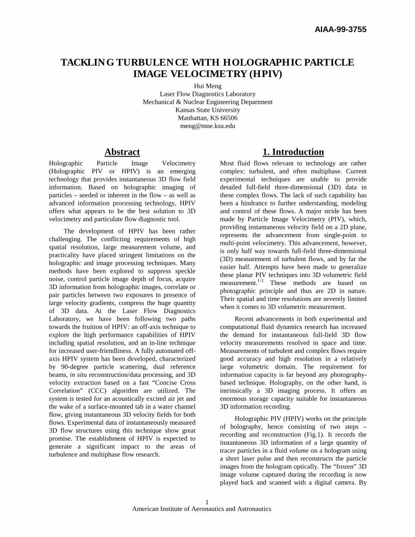
Holographic PIV (HPIV) works on the principle of holography, hence consisting of two steps – recording and reconstruction (Fig.1). It records the instantaneous 3D information of a large quantity of tracer particles in a fluid volume on a hologram using a short laser pulse and then reconstructs the particle images from the hologram optically. The “frozen” 3D image volume captured during the recording is now played back and scanned with a digital camera. By
AIAA-99-3755
American Institute of Aeronautics and Astronautics 2
finding the 3D displacements of particles in the image volume between two exposures separated by a short time lapse, an instantaneous volumetric 3D velocity field is retrieved (Fig. 2). When applied in conjunction with cinematography, both time- and
space-resolved measurements can be obtained.
The key problems that any HPIV system faces
are reduction of speckle noise, handling of huge quantities of data, extraction of 3D velocity in presence of large gradients/fluctuations, and system complexity vs. user-friendliness. While the strategies of handling all these issues make each setup unique, HPIV configurations can be broadly classified into two kinds based on the nature of the holographic scheme: “in-line”, where only one beam is employed to produce both the object wave (scattered part) and the reference wave (unscattered part), and “off-axis”, where separate object beam and reference beam(s) are introduced. Figures 1 and 2 exemplify “off-axis” and “in-line”, respectively. Many variations are possible, which often blur such distinctions.
IROV HPIV Technique Classic Gabor or in-line holography has been the traditional holographic method to diagnose particle fields 4-6 and thus was employed in holographic PIV.7-
9 While enjoying simplicity of optical geometry and low requirements for laser coherence and energy, standard in-line method, when used in HPIV, has been proven to produce excessive intrinsic speckle noise due to the superposition of its real image, virtual image and reference beam.10 Another problem with in-line holography, affecting the measurement accuracy, is the very long depth of focus of the reconstructed particle image, due to the small effective Numerical Aperture (N.A.) caused by the use of forward particle scattering.
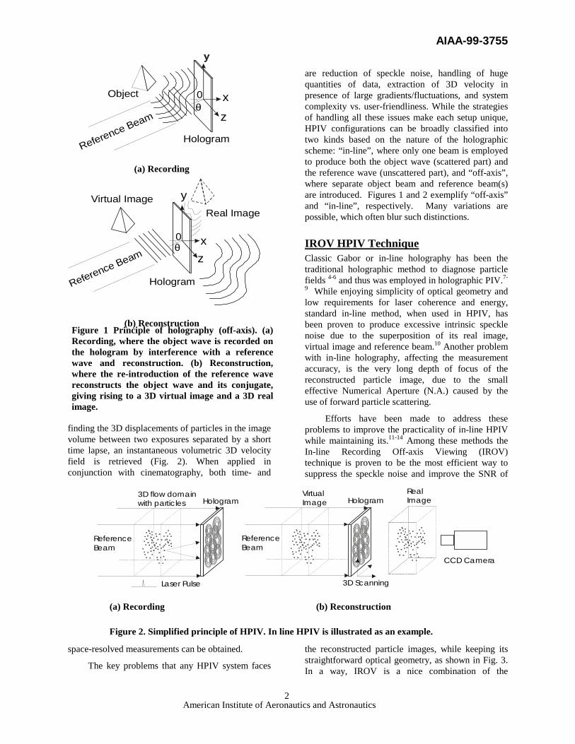
Efforts have been made to address these problems to improve the practicality of in-line HPIV while maintaining its.11-14 Among these methods the In-line Recording Off-axis Viewing (IROV) technique is proven to be the most efficient way to suppress the speckle noise and improve the SNR of
the reconstructed particle images, while keeping its straightforward optical geometry, as shown in Fig. 3. In a way, IROV is a nice combination of the
VirtualImage
3D flow domainwith partic les
RealImageHologram Hologram
CCD Camera
3D Scanning
ReferenceBeam
Laser Pulse
ReferenceBeam
(a) Recording (b) Reconstruction
Figure 2. Simplified principle of HPIV. In line HPIV is illustrated as an example.
(a) Recording
(b) Reconstruction
θxz
Reference Beam
Object
Hologram
0
xz
y
Reference Beam
Virtual ImageReal Image
Hologram
0θ
Figure 1 Principle of holography (off-axis). (a) Recording, where the object wave is recorded on the hologram by interference with a reference wave and reconstruction. (b) Reconstruction, where the re-introduction of the reference wave reconstructs the object wave and its conjugate, giving rising to a 3D virtual image and a 3D real image.
AIAA-99-3755
American Institute of Aeronautics and Astronautics 3
advantages of both in-line and off-axis holography. HPIV based on IROV has been successfully implemented and applied to instantaneous 3D flow measurements.14-16
With the innovative IROV approach, in-line HPIV has reached a certain level of applicability. Indeed, its optical simplicity makes it attractive for many applications including holographic 3D flow visualization, and hence it is one of the major HPIV techniques this lab is currently pursuing.16,17 More remarkably, owing to the lower spatial resolution compared to off-axis holography, IROV is a promising framework for digital reconstruction, which the author believes to be the future wave of HPIV.
Off-axis HPIV Technique Currently at a seeding density of no more than a few particles per mm3, the spatial resolution that IROV HPIV can achieve is normally insufficient for resolving turbulent flows. In the pursuit of high spatial resolution 3D velocity vector field measurement, off-axis holography becomes the logical choice. With this scheme, a separate reference wave is introduced to interfere with the object wave (the scattering from the particle field). During hologram reconstruction, the directly transmitted reference wave, the virtual and real image waves are naturally separated, eliminating the major source of speckle noise inherent in in-line HPIV. Hence, off-axis HPIV tolerates higher seeding densities and offers a much better image SNR. Furthermore, by utilizing side scattering rather than the central-lob forward scattering of particles, off-axis HPIV can drastically increase the effective numerical aperture (N.A.), thereby reducing the depth of focus and yielding higher measurement accuracy. Off-axis holography also allows resolving the directional ambiguity problem inherent in double-exposure HPIV by employing dual reference waves at different angles. These make off-axis HPIV an attractive approach despite the optical complexities and the high requirements on the laser power and coherence.
However, there is a trade-off between the achievable effective N.A. and the laser energy utilization, since most of the laser energy scattered by the particles is carried by the narrow-angled forward scattering.
Various off-axis methods have been proposed with various degrees of success and limitations.18-21 Identifying behavior of different noise with respect to changing N.A., we take a more practical approach to off-axis HPIV. A high effective N.A. is achieved by using 90-degree scattering, which provides homogeneous intensity distribution over a large solid angle.19 The optical configuration of the 90-degree scattering HPIV resembles that of planar PIV to a great degree, convenient for practical application.
The high image SNR achieved by our off-axis configuration alleviates the need for de-noising in the data processing stage and thus greatly improves the overall processing speed. The high SNR also brings a highly efficient, yet simple implementation of a centroid finding algorithm. By utilizing only particle centroid locations instead of raw images, a compression ratio of several orders has been achieved. At the core of HPIV data processing, a fast Concise Cross Correlation (CCC) algorithm has been implemented, which works on particle centroids, thereby drastically improving processing speed over conventional cross-correlation. With this approach the resolution can be further refined by pairing individual particles in the correlation sets by using CCC results as a reference, achieving super resolution.22
2. Off-axis HPIV System Based on the off-axis holographic principle, we implemented a fully automated experimental off-axis HPIV, which employs 90-degree scattering, dual reference beams, in-situ reconstruction, and novel 3D data processing algorithms. In this section we describe the system in detail.
Recording
Hologram VirtualImage Hologram Real
Image
Recording Reconstruction
ReferenceBeam
ReferenceBeam
ConventionalIn-line
IROV
Figure 3 IROV technique: recording is in-line (one beam); reconstruction uses off-axis (high-frequency) information.
AIAA-99-3755
American Institute of Aeronautics and Astronautics 4
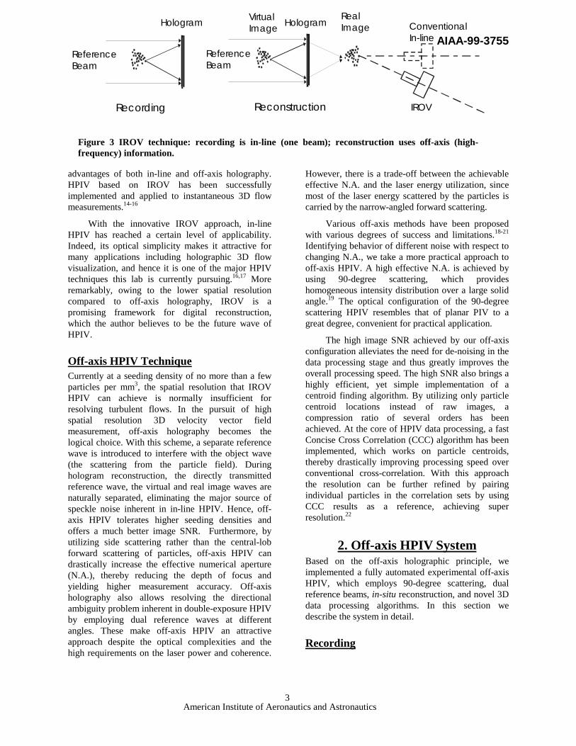
Recording is the first step in HPIV measurement. Illustrated in Fig. 4 is the optical configuration for off-axis HPIV recording. An injection-seeded dual Nd:YAG laser (Spectra-Physics PIV-400) is employed as the light source, which gives a pair of temporally and spatially separated laser pulses, each of 8ns duration, at a repetition rate of 10Hz. As in regular PIV applications, the double pulse separation ∆t is adjusted according to the estimated flow speed. The two laser units contained in the dual YAG laser system are fired by a multi-channel digital delay generator. The addition of injection seeding to the standard PIV-400 laser guarantees sufficient coherence length (over a meter), which otherwise would be less than 1 cm. The increased coherence length enables high-quality off-axis holographic recording of a large volume while allowing unmatched optical path lengths between object and reference beams. To ensure the stability of injection seeding operation, the pulsed laser system has to fire constantly during the recording process, and hence a pair of high-energy shutters operated through a synchronizer are needed to generate a single pair of laser pulses. The synchronizer assures each shutter to pass one and only one laser pulse each time.
Each laser head emits a beam, which, after
passing through a shutter, is split into two parts. The majority of the energy (80%) from each beam is combined at a common receiving HEM to form a double-pulsed illuminating beam. The beam handling unit (enclosed by dashed line) produces three output beams: two separate reference beams (Reference 1 and 2) and one combined illuminating beam. The illuminating beam is double pulsed, while the two reference beams are alternately single pulsed. This dual-reference-beam design provides angular separation of the reference beams for the double-exposure hologram, so that the two holographic images can be reconstructed alternately in time.
The reference beams are expanded and then bent over by a pair of flat mirrors to the holographic plate, which has its emulsion side facing the particle field (the flow field). The 90-degree scattered light from the particle field interferes with the reference beams, and the resultant interference pattern is recorded by the holographic plate. In this way a 90-degree scattering, dual-reference off-axis HPIV recording scheme is created.
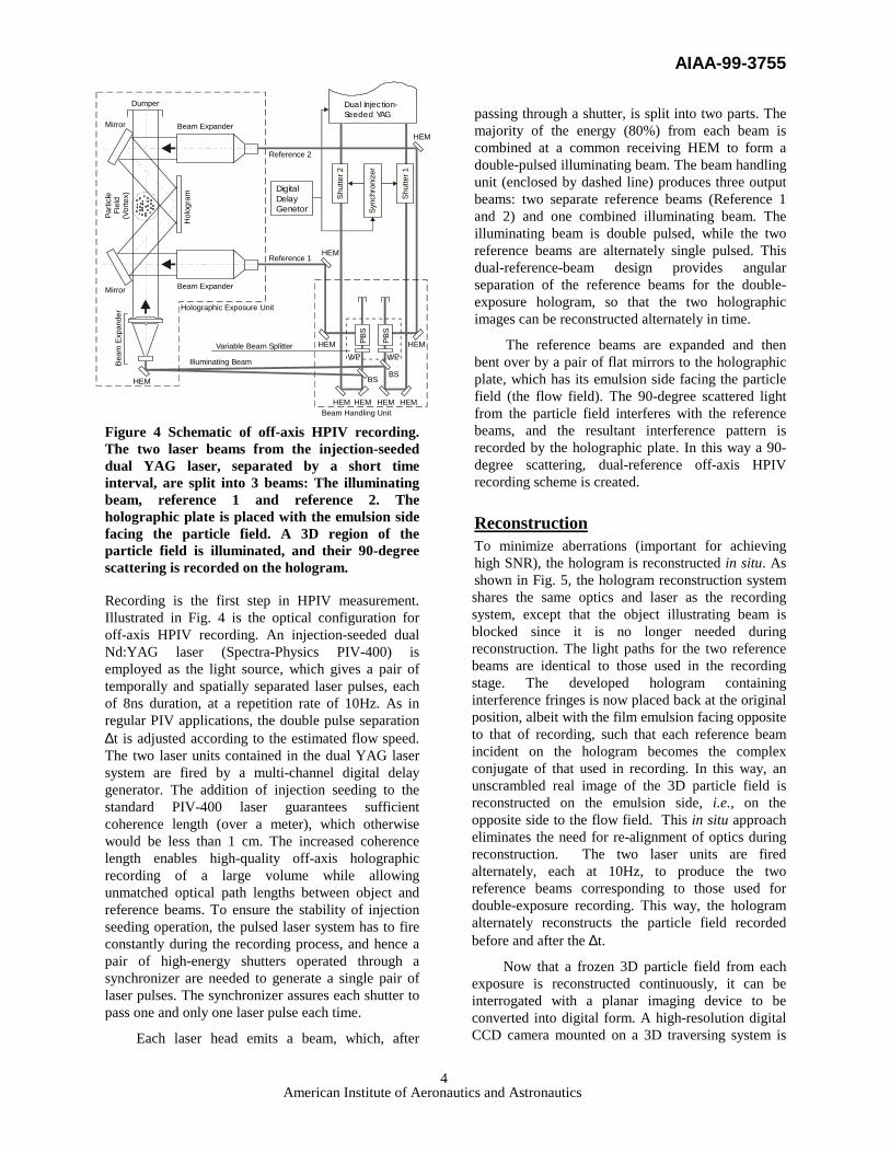
Reconstruction To minimize aberrations (important for achieving high SNR), the hologram is reconstructed in situ. As shown in Fig. 5, the hologram reconstruction system shares the same optics and laser as the recording system, except that the object illustrating beam is blocked since it is no longer needed during reconstruction. The light paths for the two reference beams are identical to those used in the recording stage. The developed hologram containing interference fringes is now placed back at the original position, albeit with the film emulsion facing opposite to that of recording, such that each reference beam incident on the hologram becomes the complex conjugate of that used in recording. In this way, an unscrambled real image of the 3D particle field is reconstructed on the emulsion side, i.e., on the opposite side to the flow field. This in situ approach eliminates the need for re-alignment of optics during reconstruction. The two laser units are fired alternately, each at 10Hz, to produce the two reference beams corresponding to those used for double-exposure recording. This way, the hologram alternately reconstructs the particle field recorded before and after the ∆t.
Now that a frozen 3D particle field from each exposure is reconstructed continuously, it can be interrogated with a planar imaging device to be converted into digital form. A high-resolution digital CCD camera mounted on a 3D traversing system is
Hol
ogra
m
Beam Expander
Beam
Exp
ande
rBeam Expander
Beam Handling Unit
Variable Beam Splitter
Reference 1
Reference 2
Mirror
Mirror
Dumper
HEM
HEM
HEM
HEM HEM HEM HEM
HEM
HEM
PBS
PBS
BS BS
WP WP
Shut
ter 1
Shut
ter 2
Parti
cle
Fiel
d(V
orte
x)
Illuminating Beam
Holographic Exposure Unit
Sync
hron
izer
Dual Injection-Seeded YAG
DigitalDelayGenetor
Figure 4 Schematic of off-axis HPIV recording. The two laser beams from the injection-seeded dual YAG laser, separated by a short time interval, are split into 3 beams: The illuminating beam, reference 1 and reference 2. The holographic plate is placed with the emulsion side facing the particle field. A 3D region of the particle field is illuminated, and their 90-degree scattering is recorded on the hologram.
AIAA-99-3755
American Institute of Aeronautics and Astronautics 5
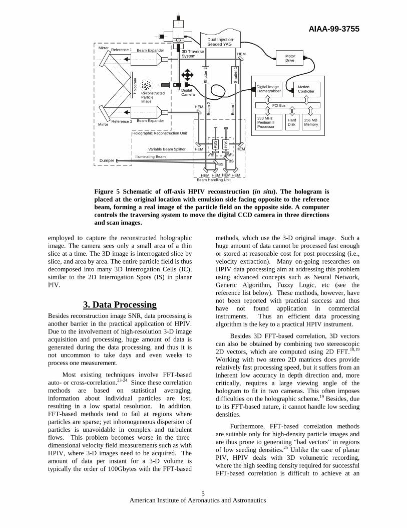
employed to capture the reconstructed holographic image. The camera sees only a small area of a thin slice at a time. The 3D image is interrogated slice by slice, and area by area. The entire particle field is thus decomposed into many 3D Interrogation Cells (IC), similar to the 2D Interrogation Spots (IS) in planar PIV.
3. Data Processing Besides reconstruction image SNR, data processing is another barrier in the practical application of HPIV. Due to the involvement of high-resolution 3-D image acquisition and processing, huge amount of data is generated during the data processing, and thus it is not uncommon to take days and even weeks to process one measurement.
Most existing techniques involve FFT-based auto- or cross-correlation.23-24 Since these correlation methods are based on statistical averaging, information about individual particles are lost, resulting in a low spatial resolution. In addition, FFT-based methods tend to fail at regions where particles are sparse; yet inhomogeneous dispersion of particles is unavoidable in complex and turbulent flows. This problem becomes worse in the three-dimensional velocity field measurements such as with HPIV, where 3-D images need to be acquired. The amount of data per instant for a 3-D volume is typically the order of 100Gbytes with the FFT-based
methods, which use the 3-D original image. Such a huge amount of data cannot be processed fast enough or stored at reasonable cost for post processing (i.e., velocity extraction). Many on-going researches on HPIV data processing aim at addressing this problem using advanced concepts such as Neural Network, Generic Algorithm, Fuzzy Logic, etc (see the reference list below). These methods, however, have not been reported with practical success and thus have not found application in commercial instruments. Thus an efficient data processing algorithm is the key to a practical HPIV instrument.
Besides 3D FFT-based correlation, 3D vectors can also be obtained by combining two stereoscopic 2D vectors, which are computed using 2D FFT.18,19 Working with two stereo 2D matrices does provide relatively fast processing speed, but it suffers from an inherent low accuracy in depth direction and, more critically, requires a large viewing angle of the hologram to fit in two cameras. This often imposes difficulties on the holographic scheme.19 Besides, due to its FFT-based nature, it cannot handle low seeding densities.
Furthermore, FFT-based correlation methods are suitable only for high-density particle images and are thus prone to generating “bad vectors” in regions of low seeding densities.25 Unlike the case of planar PIV, HPIV deals with 3D volumetric recording, where the high seeding density required for successful FFT-based correlation is difficult to achieve at an
PCI Bus
Dual Injection-Seeded YAG
Shut
ter 2
Shut
ter 1
Hol
ogra
m
3D TraverseSystem
Beam Expander
Beam Expander
Mirror
Mirror
Reference 1
Reference 2
ReconstructedParticleImage
DumperIlluminating Beam
Variable Beam Splitter
Holographic Reconstruction Unit
DigitalCamera
MotorDrive
Beam
1
Bea
m 2
HEM HEM HEM HEM
HEMHEM
HEM
HEM
WP WP
BSBS
Beam Handling Unit
PBS
PBS
Digital ImageFramegrabber
MotionController
333 MHzPentium IIProcessor
HardDisk
256 MBMemory
Figure 5 Schematic of off-axis HPIV reconstruction (in situ). The hologram is placed at the original location with emulsion side facing opposite to the reference beam, forming a real image of the particle field on the opposite side. A computer controls the traversing system to move the digital CCD camera in three directions and scan images.
AIAA-99-3755
American Institute of Aeronautics and Astronautics 6
acceptable signal-to-noise ratio due to speckle noise.10 Hence, 3D FFT-based correlation is deemed unsuitable for our off-axis HPIV system.
In a practical HPIV system, the Concise Cross Correlation (CCC) method developed at this lab appears to be an efficient technique. The idea of CCC is to compute 3-D correlation based on particle centroids. Since one frame of 1MB-sized digital image contains only a small number (usually less than 100) of particles whose centroid location can be expressed by 12 bytes of data, CCC achieves a great data compression ratio (>104). By dimensional decomposition the processing speed is also greatly accelerated. CCC also provides the means to individually pair particles, tremendously improving spatial resolution in the measurement.
Data Processing Procedure Data acquisition and processing in our off-axis HPIV system starts from acquiring the optically reconstructed “frozen” image field, using a CCD camera, with the purpose of yielding digital data. The process is fully automated and controlled by a PC. A PCI digital image framegrabber is hosted in the computer to perform image capturing, and a motion controller is also installed to position the camera through the 3-axis traverse system. Image acquisition and camera movement are synchronized with the laser pulses to ensure data integrity.
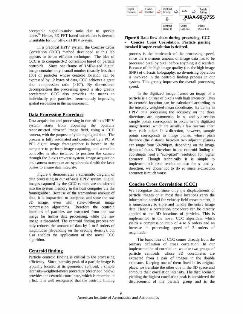
Figure 6 demonstrates a schematic diagram of data processing in our off-axis HPIV system. Digital images captured by the CCD camera are transferred into the system memory in the host computer via the framegrabber. Because of the tremendous amount of data, it is impractical to compress and store the raw 3D image, even with state-of-the-art image compression algorithms. Therefore the centroid locations of particles are extracted from the raw image for further data processing, while the raw image is discarded. The centroid finding process not only reduces the amount of data by 4 to 5 orders of magnitudes (depending on the seeding density), but also enables the application of the novel CCC algorithm.
Centroid finding Particle centroid finding is critical to the processing efficiency. Since intensity peak of a particle image is typically located at its geometric centroid, a simple intensity-weighted-mean procedure (described below) provides the centroid coordinate, which is recorded in a list. It is well recognized that the centroid finding
process is the bottleneck of the processing speed, since the enormous amount of image data has to be processed pixel by pixel before anything is discarded. Because of the high image quality (i.e. the high image SNR) of off-axis holography, no de-noising operation is involved in the centroid finding process in our system. This greatly improves the overall processing speed.
In the digitized image frames an image of a particle is a cluster of pixels with high intensity. Thus its centroid location can be calculated according to the intensity-weighted-mean coordinate. Evidently in HPIV data processing the accuracy on the three directions are asymmetric. In x- and y-direction sample points corresponds to pixels in the digitized image frames, which are usually a few microns apart from each other. In z-direction, however, sample points corresponds to image planes, whose pitch distance (the distance between two adjacent planes) can range from 50-200µm, depending on the image depth of focus. Therefore in the centroid finding z-coordinate need a “sub-pixel” resolution for higher accuracy. Though technically it is simple to implement sub-pixel resolution also for x- and y-direction, we chose not to do so since z-direction accuracy is much worse.
Concise Cross Correlation (CCC) We recognize that since only the displacements of particle images or at most their locations carry the information needed for velocity field measurement, it is unnecessary to store and handle the entire image data. Hence a correlation procedure can be directly applied to the 3D locations of particles. This is implemented in the novel CCC algorithm, which yields a compression ratio of 4 to 5 orders and an increase in processing speed of 3 orders of magnitude.
The basic idea of CCC comes directly from the primary definition of cross correlation. In our implementation of correlation, we take two groups of particle centroids, whose 3D coordinates are extracted from a pair of images in the double exposure. Keeping one of them fixed in its original place, we translate the other one in the 3D space and compute their correlation intensity. The displacement yielding the highest correlation peak is considered the displacement of the particle group and is the
DigitalCamera
Frame-Grabber
CentroidFinding CCC Particle
Pairing
CentroidData File
VectorData File
PairedVector File
Figure 6 Data flow chart during processing. CCC - Concise Cross Correlation. Particle pairing invoked if super-resolution is desired.

AIAA-99-3755
American Institute of Aeronautics and Astronautics 7
correlation output. Fig. 5 illustrates how CCC works.
Higher spatial resolution and accuracy can be further achieved by pairing individual particles after CCC finds the mean displacements of particle groups. In each Interrogation Cell, after the three components of the resultant vector are obtained through CCC, the second set of particle centroids is shifted in 3D along the vector. Now that there is no net displacement of the particle group but only net deformation between the two particle groups, pairing is accomplishable on the basis of closest distance.
4. Capability at the State of the Art The main purpose of HPIV is to obtain 3D flow velocity vector fields. It is important to realize that unlike conventional single-point measurement techniques that rely on the temporal resolution to shed light on turbulent flows, HPIV provides rich spatial information about a complex and turbulent flow that no other quantitative experimental methods can provide. Uniquely, HPIV probes directly into the 3D space. As such, it provides a new way to tackle turbulence, providing instantaneous 3D flow
structures, allowing for the application of coherent structures and the construction of strain-rate tensor. These in turn provide new opportunities to understand turbulence and validate theoretical models. Currently, our effort has been focused at increasing the information capacity (a combination of spatial resolution and measurement volume) and processing speed for instantaneous realizations. Only when this stage becomes mature will cinematic HPIV be sensible.
With the off-axis system described in this paper, the average particle seeding can go as high as 50 per mm3, yielding a spatial resolution (after particle pairing) of roughly 0.3mm. The measurement volume, based on current size of the optics, is roughly 60mm x 60mm x 60mm. Hence the largest-to-smallest length scale ratio of measurement is roughly 200. Further increase of imaging volume and hence increase of the scale ratio can be achieved by scaling up the optics and, possibly, by increasing seeding density. The latter calls for more powerful ways to ensure SNR.
The dynamic range of the velocity measurement is determined by the ratio of 1/3 of the Interrogation Cell size (largest displacement) and the particle centroid identification accuracy (the smallest displacement). By using a cascade procedure in data processing, the initial IC size can be rather large. The centroid accuracy is better than 4 µm along the transverse directions (perpendicular to the optic axis of image acquisition), but 5-6 times worse along the axis. In the latter case, sub-“pixel” resolution is needed. It is appropriate to estimate the typical dynamic range of velocity measurement to be 3 decades.
A secondary purpose of HPIV, pertaining to multiphase flow application, is to diagnose particle position and velocity information. This is possible with our off-axis HPIV technique, since the individual particle information is preserved. By using two types of particles with rather different Stokes numbers (one of them being much less than 1 and the other greater than 1), one can diagnose both the continuous phase and the discrete phase. This application is not the main focus of the current paper.
5. Experimental Results The Off-axis HPIV technique is applied to a water channel flow with a tapered passive mixing tab mounted on the wall. The wake of such a tab is known to produce complex 3D vortical motions including a series of hairpin vortices 26,27 and thus the
(a) Before translation
Figure 7 Principle of Concise Cross Correlation (CCC). (a) Two groups of particle centroids (white and black balls) correspond to two exposures. Gray balls represent noise. (b) During calculation one group (white balls) and some of the noise are translated in space, until their morphological pattern best matches that of the other group (black balls).
(b) After translation
AIAA-99-3755
American Institute of Aeronautics and Astronautics 8
tab is often called vortab. The free-stream flow velocity is approximately 16.7cm/s, corresponding to Re ~ 12,000 based on the channel height and 2080 based on the tab height.
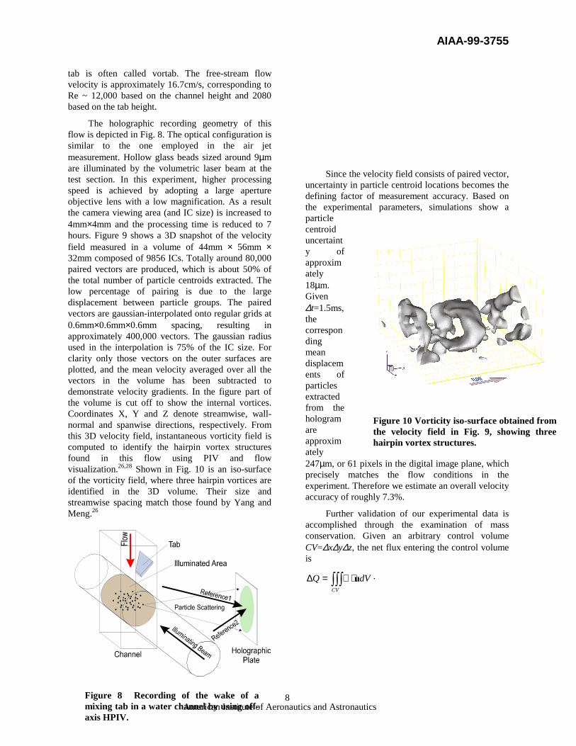
The holographic recording geometry of this flow is depicted in Fig. 8. The optical configuration is similar to the one employed in the air jet measurement. Hollow glass beads sized around 9µm are illuminated by the volumetric laser beam at the test section. In this experiment, higher processing speed is achieved by adopting a large aperture objective lens with a low magnification. As a result the camera viewing area (and IC size) is increased to 4mm×4mm and the processing time is reduced to 7 hours. Figure 9 shows a 3D snapshot of the velocity field measured in a volume of 44mm × 56mm × 32mm composed of 9856 ICs. Totally around 80,000 paired vectors are produced, which is about 50% of the total number of particle centroids extracted. The low percentage of pairing is due to the large displacement between particle groups. The paired vectors are gaussian-interpolated onto regular grids at 0.6mm×0.6mm×0.6mm spacing, resulting in approximately 400,000 vectors. The gaussian radius used in the interpolation is 75% of the IC size. For clarity only those vectors on the outer surfaces are plotted, and the mean velocity averaged over all the vectors in the volume has been subtracted to demonstrate velocity gradients. In the figure part of the volume is cut off to show the internal vortices. Coordinates X, Y and Z denote streamwise, wall-normal and spanwise directions, respectively. From this 3D velocity field, instantaneous vorticity field is computed to identify the hairpin vortex structures found in this flow using PIV and flow visualization.26,28 Shown in Fig. 10 is an iso-surface of the vorticity field, where three hairpin vortices are identified in the 3D volume. Their size and streamwise spacing match those found by Yang and Meng.26
Since the velocity field consists of paired vector, uncertainty in particle centroid locations becomes the defining factor of measurement accuracy. Based on the experimental parameters, simulations show a particle centroid uncertainty of approximately 18µm. Given ∆t=1.5ms, the corresponding mean displacements of particles extracted from the hologram are approximately 247µm, or 61 pixels in the digital image plane, which precisely matches the flow conditions in the experiment. Therefore we estimate an overall velocity accuracy of roughly 7.3%.
Further validation of our experimental data is accomplished through the examination of mass conservation. Given an arbitrary control volume CV=∆x∆y∆z, the net flux entering the control volume is
∫∫∫ ⋅∇=∆CV
dVQ u .
Figure 10 Vorticity iso-surface obtained from the velocity field in Fig. 9, showing three hairpin vortex structures.
Figure 8 Recording of the wake of a mixing tab in a water channel by using off-axis HPIV.

AIAA-99-3755
American Institute of Aeronautics and Astronautics 9
For incompressible flows ∆Q≡0. To estimate the order of the net flux we introduce a characteristic velocity U, which is the main flow velocity in the flow field. The total flux passing through the control volume can be estimated as
zyUQ ∆∆⋅=
Therefore the non-dimensional ratio
QQ∆=η
provides a good indication of how well the continuity equation is satisfied.
From the 3D velocity field the divergence is computed based on finite difference. The Probability Density Function (PDF) of divergence is depicted in Fig. 11. It is found that the divergence has a mean value of 0.51s-1 and a standard deviation of 6.63s-1. The absolute value of divergence has a mean value of 5.11s-1 and 95% of data points are within divergence absolute value of 12.9s-1. Thus choosing the 95% coverage divergence and the smallest control volume size (the grid size) for a worst case estimation, we estimate that ∆Q is circa 2.78mm3/s. On the other hand, the mean flow velocity can be chosen as the characteristic velocity and Q is estimated to be around 59.0 mm3/s. Therefore we estimate η ~ 4.7%.
7. Summary In this paper we describe an advanced off-axis HPIV system with fully automated data processing. Its distinct features include the use of 90-degree scattering, dual reference beam recording, in situ reconstruction, on-the-fly processing, and a novel Concise Cross Correlation (CCC) algorithm based on particle centroids. Our off-axis HPIV configuration offers superior image SNR at relatively high seeding density, alleviating the need for de-noising in data processing and enabling the use of CCC algorithm. A great gain on processing speed and data compression
Figure 9 An instantaneous 3D velocity field in the tab wake obtained by HPIV. The measurement volume is 44mm ×××× 56mm ×××× 32mm. Approximately 400,000 3D vectors have been gaussian-interpolated from about 80,000 paired vectors extracted with CCC and particle pairing. Mean velocity of the vectors has been subtracted. Only surface vectors are shown.
0
0.5
1
1.5
2
2.5
3
3.5
4
-44
-39
-34
-29
-24
-19
-14
-8.7
-3.5
1.57
6.68
11.8
16.9
22 27.1
32.3
37.4
Divergence (1/s)
Perc
enta
ge o
f Dat
a Po
ints
Figure 11 PDF of divergence calculated from the experimental data. The mean value of divergence is 0.51s-1, and its standard deviation is 6.62s-1. 95% of the data points are with in 12.9s-1.

AIAA-99-3755
American Institute of Aeronautics and Astronautics 10
ratio is achieved over traditional methods by using CCC. This innovative correlation approach also makes particle pairing possible, which greatly increases the spatial resolution. The off-axis HPIV technique has been successfully tested on two flows including an acoustically excited air jet seeded with water droplets and a surface-tab water channel flow. From both flows instantaneous 3D velocity fields are measured, from which vortex structures (a vortex ring and a series of hairpin structures) based on vorticity magnitude are obtained.
Acknowledgement The author wish to thank the National Science Foundation and Air Force Office of Scientific Research for their support and Ye Pu for critical contribution to this project.
REFERENCE 1. Guezennec, Y. G. Zhao, Y. and Gieseke, T. J.
1994, High-speed 3-D scanning particle image velocimetry (3-D SPIV) technique, Proc. Laser Symp., Lisbon, paper26.1.
2. Bruecker, Ch. 1995, 3-D DPIV using a scanning light-sheet and stereoscopy: study of flow development around a spherical cap, ASME FED 229, pp. 497-503.
3. Bruecker, Ch. 1997, 3D scanning PIV applied to an air flow in a motored engine using digital high-speed video, Meas. Sci. Technol. 8 pp. 1480-1492
4. Trolinger, J. D. and Belz, R. A. 1973, Holography in dust erosion facilities, AEDC-TR-73-160.
5. Thompson, B. J. 1974, Holographic particle sizing technique, J. Phys. E. 7, pp. 781-788.
6. Belz, R. A. and Menzel, R. W. 1979, Particle field holography at Arnold Engineering Development Center, Opt. Eng. 8, pp. 256-265.
7. Weinstein, L. W., Beeler, G. B. and Linderman, A. M. 1985, AIAA-85-0526.
8. Meng, H. and Hussain, F. 1991, Holographic particle velocimetry: a 3D measurement technique for vortex interactions, coherent structures and turbulence, Fluid Dyn. Res., 8, pp. 33-52.
9. Scherer, J. O. and Bernal, L. P. 1997, In-line holographic particle image velocimetry for turbulent flows, Appl. Opt. 36, pp. 9309-9318.
10. Meng, H., Anderson, W. L., Hussain, F., and Liu, D. 1993, Intrinsic speckle noise in in-line particle holography, J. Opt. Soc. of Am 10 pp. 2046-2058.
11. Simmons, S., Meng, H. Hussain, F. and Liu, D. 1993, Advances in holographic particle velocimetry, SPIE 2005, San Diego, pp. 11-16.
12. Zimin, V., Meng, H., and Hussain, F. 1993, An innovative holographic particle velocimeter: multibeam technique, Optics Letters, 18, pp. 1101-1103.
13. Zimin, V. and Hussain, F. 1994, High-aperture raster holography for particle imaging, Opt. Let. 19, pp. 1158-1160.
14. Meng, H. and Hussain, F. 1995, In-line Recording and Off-axis Viewing (IROV) technique for holographic particle velocimetry, Appl. Opt. 34, pp. 1827-1840.
15. Meng, H. and Hussain, F. 1995, Instantaneous flow field in a circular vortex ring captured by innovative holographic particle velocimetry, Phys. Fluids 7, pp. 9-11.
16. Sheng, J., and Meng, H. 1998, A Genetic Algorithm approach for 3D velocity field extraction in holographic particle image velocimetry, Exp. Fluids. 25, pp. 461-473.
17. Meng, H., Estevadeordal, J., Gogeneni, S., Goss, L. and Roquemore, W. M. 1998, Holographic flow visualization as a tool for studying 3D coherent structures and instabilities, J. Visualization, 1, 51-63.
18. Barnhart, D. H., Adrian, R. J., Meinhart, C. D. and Papen, G. C., 1994, Phase-conjugate holographic system for high-resolution particle image velocimetry, Appl. Opt. 33, pp.7159-7169.
19. Meng, H. 1994, Development of Holographic Particle Velocimetry Techniques for Three-dimensional Vortical Flows, Ph.D. disertation, University of Houston, Houston, TX.
20. Liu, D. D. and Hussain, F. 1995, Off-axis holographic technique for particle image velocimetry using a Fourier-transform lens, Optics Letters, 20, 327-329.
21. Zhang, J., Tao, B., and Katz, J. 1997, Turbulent flow measurement in a square duct with hybrid holographic PIV, Exp. Fluids, 23, 373-381
22. Keane, R. D., Adrian, R. J. and Zhang, Y. 1995, Super-resolution particle image velocimetry, Meas. Sci. Technol. 6, pp. 754-768.
23. Gray, C. and Greated, C. A. 1993, Processing
AIAA-99-3755
American Institute of Aeronautics and Astronautics 11
system for the analysis of particle displacement holograms, SPIE 2005, San Diego, pp. 636-647.
24. Huang, K., Slepicka, J. and Cha, S. S. 1993, Cross-correlation of three-dimensional images for three-dimensional three-component fluid velocity measurements, SPIE 2005, pp. 655-666.
25. Meinhart, C. D., Adrian, R. J. 1995, Measurement of the zero-pressure gradient turbulent boundary layer using particle image velocimetry, AIAA 95-0789, Wash. D. C.
26. Yang, W. and Meng 1998, H. Regeneration of hairpin vortices in the wake of a surface-mounted mixing tab, submited to J. Fluid Mech.
27. Gretta, W. J. and Smith, C. R. 1993, Flow structure and statistics of a passive mixing tab, J. Fluids Eng., Trans. ASME 2 pp. 255-263.
28. Elavarasan, R. and Meng 1998, H., Flow visualization study of role of coherent structures in a tab wake, submitted to Fluid Dyn. Res.