tag-along trailer kit · 2017-07-25 · page 4 of 28 intended use the ultra-tow tag-along trailer...
TRANSCRIPT

READ & SAVE THESE INSTRUCTIONS
Tag-Along Trailer Kit
Owner’s Manual
WARNING: Read carefully and understand all ASSEMBLY AND OPERATION
INSTRUCTIONS before operating. Failure to follow the safety rules and other basic safety
precautions may result in serious personal injury.
Item #57762

Page 2 of 28
Thank you very much for choosing an Ultra-Tow™ product!
For future reference, please complete the owner’s record below:
Serial Number/Lot Date Code: ________________________________
Purchase Date: ____________________________________________
Save the receipt, warranty, and this manual. It is important that you read
the entire manual to become familiar with this product before you begin
using it.
This trailer is designed for certain applications only. Northern Tool and
Equipment is not responsible for issues arising from modification or
improper use of this product such as an application for which it was not
designed. We strongly recommend that this product not be modified
and/or used for any application other than that for which it was designed.
For technical questions, please call 1-800-222-5381.

Page 3 of 28
Table of Contents
Intended Use .......................................................................................................................................... 4
Packaging Contents .............................................................................................................................. 4
Technical Specifications ...................................................................................................................... 5
Important Safety Information ............................................................................................................... 5
Specific Operation Warnings ............................................................................................................... 6
Main Parts of Trailer .............................................................................................................................. 7
Assembly Instructions ........................................................................................................................ 10
Before Each Use .................................................................................................................................. 14
Operating Instructions ........................................................................................................................ 15
After Each Use ..................................................................................................................................... 21
Maintenance ........................................................................................................................................ 21
Troubleshooting .................................................................................................................................. 23
Parts Diagram ...................................................................................................................................... 24
Parts List .............................................................................................................................................. 25
Replacement Parts .............................................................................................................................. 26
Limited Warranty ................................................................................................................................. 27

Page 4 of 28
Intended Use
The Ultra-Tow Tag-Along Trailer Kit adds 16 cubic feet of storage space to your car, truck, or
motorcycle. There is a 600 lb. max capacity for the vehicle and a 200 lb. max for the motorcycle. The
trailer features a lockable shell lid to keep items protected from damage as well as self-assisted
hydraulic struts for easy opening. It includes a coupler, safety chain, wiring harness, trailer light kit,
license plate holder, two keys, and two additional side latches.
Packaging Contents
Part Description Qty.
Part Description Qty.
1 Trailer Body 1
24 Bolt (M10 x 40) 4
2 Leaf Spring 2
25 Bolt (M12 x 80) 4
3 Axle 1
26 Bolt (M10 x 70) 1
4 Hubs 2
27 Bolt (M10 x 90) 2
5 Tire 2
28 Bolt (M6 x 45) 2
6 Drawbar 1
29 Washer (ø10) 8
7 Coupler 1
30 Washer (ø6) 12
8 Safety Chain 1
31 Washer (ø8) 8
9 Side Running Light 2
32 Lock Nut (M6) 14
10 Left Tail Light 1
33 Lock Nut (M8) 7
11 Right Tail Light 1
34 Lock Nut (M10) 21
12 License Plate Bracket 1
35 Lock Nut (M12) 4
13L Fender L 1
36 U-Bolt (10-100x53) 4
13R Fender R 1
37 U-Bolt (10-85x78) 3
14 Upper Shell 1
38 Lug Nut 8
15 Bottom Shell 1
39 Rubber Pad 4
16 Hinge Bracket 2
40 Cooler Rack 1
17 Gas Spring 2
41 Mounting Plate 2
18 Snap Latch 2
42 Latch 1
19 Body Bracket 2
43 Stand 1
20 Lock Bracket 1
44 Bumper 1
21 Key 2
45 Bolt (M8 x 20) 2
22 Spring Plate 2
46 Latch Spring 1
23 Bolt (M6 x 20) 12

Page 5 of 28
Technical Specifications
Property Specification
Tow Ball (required) 1-7/8" (not supplied)
Tire Air Pressure Maximum 60 PSI (cold)
Capacity - Auto 600 lb.
Capacity - Motorcycle 200 lb.
Storage Space 16 Cubic Feet
Important Safety Information
⚠WARNING
Read and understand all instructions. Failure to follow all instructions may result in serious injury or
property damage.
The warnings, cautions, and instructions in this manual cannot cover all possible conditions or
situations that could occur. Exercise common sense and caution when using this tool. Always be
aware of the environment and ensure that the tool is used in a safe and responsible manner.
Do not allow persons to operate or assemble the product until they have read this manual and have
developed a thorough understanding of how it works.
Do not modify this product in any way. Unauthorized modification may impair the function and/or
safety and could affect the life of the product. There are specific applications for which the product
was designed.
Use the right tool for the job. DO NOT attempt to force small equipment to do the work of larger
industrial equipment. There are certain applications for which this equipment was designed. This
product will be safer and do a better job at the capacity for which it was intended. DO NOT use this
equipment for a purpose for which it was not intended.
Industrial or commercial applications must follow OSHA requirements.
⚠WARNING
WORK AREA SAFETY
Inspect the work area before each use. Keep work area clean, dry, free of clutter, and well-lit.
Cluttered, wet, or dark work areas can result in injury. Using the product in confined work areas may
put you dangerously close to cutting tools and rotating parts.
Do not use the product where there is a risk of causing a fire or an explosion; e.g., in the presence of
flammable liquids, gases, or dust. The product can create sparks, which may ignite the flammable
liquids, gases, or dust.
Do not allow the product to come into contact with an electrical source. The tool is not insulated and
contact will cause electrical shock.
Keep children and bystanders away from the work area while operating the tool. Do not allow
children to handle the product.

Page 6 of 28
⚠WARNING
PERSONAL SAFETY
Stay alert, watch what you are doing, and use common sense when operating the tool. Do not use
the tool while you are tired or under the influence of drugs, alcohol, or medication. A moment of
inattention while operating the tool may result in serious personal injury.
Dress properly. Do not wear loose clothing, dangling objects, or jewelry. Keep your hair, clothing and
gloves away from moving parts. Loose clothes, jewelry, or long hair can be caught in moving parts.
Air vents on the tool often cover moving parts and should be avoided.
Wear the proper personal protective equipment when necessary. Use ANSI Z87.1 compliant safety
goggles (not safety glasses) with side shields, or when needed, a face shield. Use a dust mask in
dusty work conditions. Also use non-skid safety shoes, hardhat, gloves, dust collection systems,
and hearing protection when appropriate. This applies to all persons in the work area.
Do not overreach. Keep proper footing and balance at all times.
Remove keys or wrenches before connecting the tool to an air supply, power supply, or turning on
the tool. A wrench or key that is left attached to a rotating part of the tool may cause personal injury.
Secure the work with clamps or a vise instead of your hand when practical. This safety precaution
allows for proper tool operation using both hands.
⚠CAUTION
TRAILER USE AND CARE
Do not force the trailer. Products are safer and do a better job when used in the manner for which
they are designed. Plan your work, and use the correct product for the job.
Check for damaged parts before each use. Carefully check that the product will operate properly
and perform its intended function. Replace damaged or worn parts immediately. Never operate the
product with a damaged part.
Store the product when it is not in use. Store it in a dry, secure place out of the reach of children.
Inspect the tool for good working condition prior to storage and before re-use.
Use only accessories that are recommended by the manufacturer for use with your product.
Accessories that may be suitable for one product may create a risk of injury when used with another
tool. Never use an accessory that has a lower operating speed or operating pressure than the tool
itself.
Keep guards in place and in working order. Never operate the product without the guards in place.
Do not leave the tool running unattended.
Specific Operation Warnings
⚠WARNING
Before each use, always examine the trailer for proper tire condition and air pressure, damaged Tail
Lights, damaged Side Running Lights, loose bolts and nuts, structural cracks, bends and any other

Page 7 of 28
condition that may affect its safe operation. Do not use the Trailer even if minor damage appears.
Before each use, always attach the Safety Chains of the trailer to the towing vehicle. Make sure the
Safety Chains are attached to the towing vehicle with the equal length at each side. Do not allow
the Safety Chains to drag on the ground.
Always check to make sure the payload being transported properly and safely secured in the trailer.
Load the Trailer evenly from side to side with 60% of the load forward of the Axle.
Make sure the towing vehicle is capable of towing this trailer and its payload. Make sure the hitch
on the towing vehicle is capable of towing the Trailer and its payload. The towing capacity of the
hitch is typically stamped on the hitch drawbar.
Make sure the hitch coupler and the vehicle’s Ball Hitch (not included) are of equal mating size and
are rated equal to or greater than the weight of the trailer and its payload.
Do not exceed 45 miles per hour when towing the trailer. Excess speed is a major cause of
vehicle-trailer accidents.
The Tail Light Bulbs supplied with this trailer are for a 12 Volt DC electrical system only. Do not
attempt to power the Light Bulbs with any other type or voltage electrical current.
Whenever possible, park the trailers on a flat, level, paved surface and chock both tries to keep the
trailer from accidently moving.
DO NOT exceed the rated load capacity.
DO NOT allow anyone to ride in the towed vehicle or on the trailer.
The coupler must be properly secured to the hitch ball. After assembly and attachment, pull up and
down on the hitch coupler to make sure the hitch ball is snug in the hitch coupler. If the coupler is
not secured properly, it could come loose while the trailer is in motion, causing property damage,
serious personal injury or even death.
This trailer was not designed for use in commercial applications. Commercial use will void warranty. DO NOT USE FOR AIRCRAFT PURPOSES.
Make wide turns when towing a loaded trailer, avoiding both sharp turns and U-turns. Turning too
sharply can cause damage to the trailer and/or the tow vehicle.
Main Parts of Trailer
THE MANUFACTURER AND/OR DISTRIBUTOR HAS PROVIDED THE PARTS LIST AND
ASSEMBLY DIAGRAM IN THIS MANUAL AS A REFERENCE TOOL ONLY. NEITHER THE
MANUFACTURER NOR DISTRIBUTOR MAKES ANY REPRESENTATION OR WARRANTY OF ANY
KIND TO THE BUYER THAT HE OR SHE IS QUALIFIED TO MAKE ANY REPAIRS TO THE
PRODUCT, OR THAT HE OR SHE IS QUALIFIED TO REPLACE ANY PARTS OF THE PRODUCT.
IN FACT, THE MANUFACTURER AND/OR DISTRIBUTOR EXPRESSLY STATES THAT ALL
REPAIRS AND PARTS REPLACEMENTS SHOULD BE UNDERTAKEN BY CERTIFIED AND
LICENSED TECHNICIANS, AND NOT BY THE BUYER. THE BUYER ASSUMES ALL RISK AND
LIABILITY ARISING OUT OF HIS OR HER REPAIRS TO THE ORIGINAL PRODUCT OR
REPLACEMENT PARTS THERETO, OR ARISING OUT OF HIS OR HER INSTALLATION OF
REPLACEMENT PARTS.

Page 8 of 28

Page 9 of 28
Part Description Qty. Part Description Qty.
1 Trailer Body 1 24 Bolt (M10 x 40) 4
2 Leaf Spring 2 25 Bolt (M12 x 80) 4
3 Axle 1 26 Bolt (M10 x 70) 1
4 Hubs 2 27 Bolt (M10 x 90) 2
5 Tire 2 28 Bolt (M6 x 45) 2
6 Drawbar 1 29 Washer (10) 8
7 Coupler 1 30 Washer (6) 12
8 Safety Chain 1 31 Washer (8) 8
9 Side Running Light 2 32 Lock Nut (M6) 14
10 Left Tail Light 1 33 Lock Nut (M8) 7
11 Right Tail Light 1 34 Lock Nut (M10) 21
12 License Plate Bracket 1 35 Lock Nut (M12) 4
13L Fender L 1 36 U-Bolt (10-100x53) 4
13R Fender R 1 37 U-Bolt (10-85x78) 3
14 Upper Shell 1 38 Lug Nut 8
15 Bottom Shell 1 39 Rubber Pad 4
Page 10 of 28
Part Description Qty. Part Description Qty.
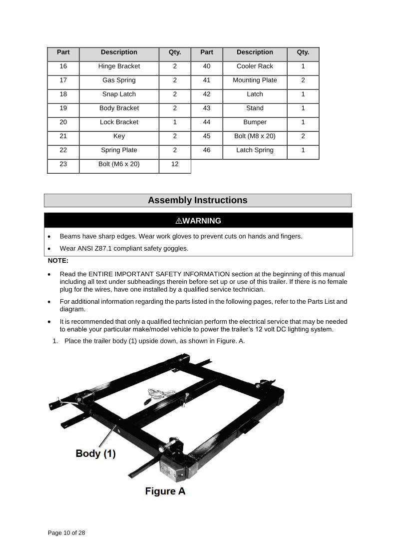
16 Hinge Bracket 2 40 Cooler Rack 1
17 Gas Spring 2 41 Mounting Plate 2
18 Snap Latch 2 42 Latch 1
19 Body Bracket 2 43 Stand 1
20 Lock Bracket 1 44 Bumper 1
21 Key 2 45 Bolt (M8 x 20) 2
22 Spring Plate 2 46 Latch Spring 1
23 Bolt (M6 x 20) 12
Assembly Instructions
⚠WARNING
Beams have sharp edges. Wear work gloves to prevent cuts on hands and fingers.
Wear ANSI Z87.1 compliant safety goggles.
NOTE:
Read the ENTIRE IMPORTANT SAFETY INFORMATION section at the beginning of this manual including all text under subheadings therein before set up or use of this trailer. If there is no female plug for the wires, have one installed by a qualified service technician.
For additional information regarding the parts listed in the following pages, refer to the Parts List and diagram.
It is recommended that only a qualified technician perform the electrical service that may be needed to enable your particular make/model vehicle to power the trailer’s 12 volt DC lighting system.
1. Place the trailer body (1) upside down, as shown in Figure. A.

Page 11 of 28
2. Use the bolts (25) and lock nuts (35) to fasten the leaf springs (2) onto the sides of the trailer body. Mount the leaf springs with the mounting eye facing towards the front of the trailer. See Figure B.
3. Place the axle (3) on top of the leaf springs.
4. Fasten the axle to the leaf plates. Do this by placing the spring plates (22) under the leaf springs. Then slide the U-bolts (36) over the axle and through the holes in the spring plates. Lock the U-bolts into place by using the lock nuts (34). See Figure D.

Page 12 of 28
5. Place tires (5) onto the hubs (4) at the end of the axle. Lock tires into place using the lug nuts (38).
Note: Use two jack stands (not included) to support the axle while the tires are being attached.
6. Connect the drawbar (6) with bolt (26) and lock nuts (34) to the center cross member of the trailer body, and attach the drawbar to the first cross member of the trailer body with U bolts (37) and lock nuts (34).
7. With assistance, turn the trailer over so that axle is under trailer body. Block both tires in front and back.
8. Once the trailer is in the correct upright position, use the bolts (23), lock nuts (32), and washer (30) to mount the fenders (13) to the tabs that extend out in behind the tires. See Figure E.

Page 13 of 28
9. The left tail light (10) and right tail light (11) are pre-wired but need to be attached to back of fenders, along with the license plate bracket (12). The tail light wire pigtails run from the fenders through the trailer body and connect to the wiring at the back of the drawbar. See Figure F.
⚠WARNING
Use care to secure the tail light wiring inside the fenders and away from the tires.
10. Use a bolt (27) and lock nut (34) to mount the coupler (7) to the front of the drawbar.
11. Use bolts (24), nuts (34), rubber pads (39), and washers (29) to fasten the body bracket (19) to the bottom shell (15) and then the bottom shell to the top of the trailer body.

Page 14 of 28
⚠WARNING
Make sure the rubber pads are placed between the underside of the body bracket and surface of trailer during assembly.
12. Use bolts (23), lock nuts (32), and washers (30) to fasten snap latches (18) to the top inside of the upper shell (14). The snap latches will be used to keep the top shell shut during use.
13. Use bolts (28), lock nuts (32), and washers (30) to fasten the hinge brackets (16) to the side interior of the upper shell.
14. Use lock nuts (33) and washers (31) to fasten the ends of the gas springs (17) to the bottom front and back sides of the bottom shell and the front and back sides of the upper shell.
15. Connect the cooler rack to the draw bar with a U-bolt (37) with plate (41) with lock nuts (34).
16. Connect the rear bumper to the trailer body with a bolt (45) and lock nuts (33).
17. Once assembly is complete, test the trailer. Do this by rolling several times to make sure the tires roll smoothly and are in proper alignment. Open and close the upper shell to make sure it is properly aligned and closes and locks securely. Make sure all hardware is fastened tightly. Once these safety checks have been done, the trailer is ready for use.
Before Each Use
⚠WARNING
Before each use, always examine the trailer for proper tire condition and air pressure, damaged Tail
Lights, damaged Side Running Lights, loose bolts and nuts, structural cracks, bends and any other
condition that may affect its safe operation. Do not use the Trailer even if minor damage appears.
Before each use, always attach the Safety Chains of the trailer to the towing vehicle. Make sure the
Safety Chains are attached to the towing vehicle with the equal length at each side. Do not allow
the Safety Chains to drag on the ground.
Make sure hitch, coupler, draw bar, and other equipment that connect the trailer and the tow vehicle
are properly secured and adjusted.
Make sure the hitch coupler and the vehicle’s Ball Hitch (not included) are of equal mating size and
are rated equal to or greater than the weight of the trailer and its payload.
The coupler must be properly secured to the hitch ball. After assembly and attachment, pull up and
down on the hitch coupler to make sure the hitch ball is snug in the hitch coupler. If the coupler is
not secured properly, it could come loose while the trailer is in motion, causing property damage,
serious personal injury or even death.
Make sure wiring is properly connected — not touching the road, but loose enough to make turns
without disconnecting or damaging the wires.
Check that all items are securely fastened on and in the trailer.
Be sure the trailer jack, tongue support, and any attached stabilizers are raised and locked in place.
Check the load distribution to make sure the tow vehicle and trailer are properly balanced front to
back and side to side.
Check side- and rear-view mirrors to make sure you have good visibility.
Check routes and restrictions on bridges and tunnels.
Make sure you have wheel chocks and jack stands.

Page 15 of 28
Always check to make sure the payload being transported properly and safely secured in the trailer.
Load the Trailer evenly from side to side with 60% of the load forward of the Axle.
Make sure the towing vehicle is capable of towing this trailer and its payload. Make sure the hitch
on the towing vehicle is capable of towing the Trailer and its payload. The towing capacity of the
hitch is typically stamped on the hitch drawbar.
Operating Instructions
⚠WARNING
Always check to make sure the payload being transported properly and safely secured in the trailer.
Load the Trailer evenly from side to side with 60% of the load forward of the Axle.
Make sure the towing vehicle is capable of towing this trailer and its payload. Make sure the hitch
on the towing vehicle is capable of towing the Trailer and its payload. The towing capacity of the
hitch is typically stamped on the hitch drawbar.
Make sure the hitch coupler and the vehicle’s Ball Hitch (not included) are of equal mating size and
are rated equal to or greater than the weight of the trailer and its payload.
Do not exceed 45 miles per hour when towing the trailer. Excess speed is a major cause of
vehicle-trailer accidents.
The Tail Light Bulbs supplied with this trailer are for a 12 Volt DC electrical system only. Do not
attempt to power the Light Bulbs with any other type or voltage electrical current.
Whenever possible, park the trailers on a flat, level, paved surface and chock both tries to keep the
trailer from accidently moving.
DO NOT exceed the rated load capacity.
DO NOT allow anyone to ride in the towed vehicle or on the trailer.
The coupler must be properly secured to the hitch ball. After assembly and attachment, pull up and
down on the hitch coupler to make sure the hitch ball is snug in the hitch coupler. If the coupler is
not secured properly, it could come loose while the trailer is in motion, causing property damage,
serious personal injury or even death.
This trailer was not designed for use in commercial applications. Commercial use will void warranty. DO NOT USE FOR AIRCRAFT PURPOSES.
Make wide turns when towing a loaded trailer, avoiding both sharp turns and U-turns. Turning too
sharply can cause damage to the trailer and/or the tow vehicle.
Connecting
1. Hitch the trailer to the tow vehicle before loading the items to be towed. Only use a 1-7/8" ball hitch (not included) on the towing vehicle.
NOTE: To reduce friction between the hitch ball and hitch coupler (7), apply a thin layer of heavy weight grease over the hitch ball.
2. Pull up on the trigger and lift up on the handle.
3. With assistance, place the hitch coupler over the vehicle’s hitch ball, pull back on the trigger, and push down on the handle until the trigger locks in the slot.

Page 16 of 28
4. Pull up and down on the coupler to make sure the hitch ball is fitting snugly in the coupler. There must be no play between the hitch ball and coupler. If there is play, tighten the adjusting nut until no play is present.
After unlocking the handle, the nut retaining plate (holding the adjusting nut in place) needs to be pressed back while the nut is tightened. After the nut is tightened, the retaining plate needs to fit in place against the flat of the nut to prevent it from moving. This adjustment should be done by two
people. If the nut is adjusted too tightly, the handle will not lock.
5. After the adjusting nut is properly adjusted, pull back on the trigger and push down on the handle until the trigger locks in the slot. Pull up on the handle firmly to make sure the trigger is locked in place and the handle cannot move. Replace the locking pin and 2mm R-clip.
6. Attach each of the safety chains (8) equally to the towing vehicle’s rear bumper or frame. Make sure the safety chains are secured safely to the trailer and the tow vehicle. Do not allow the safety chains to touch the ground while towing the trailer.
7. Connect the wiring harness to the vehicle’s 12 volt DC system. Connect the tail light wiring to the tow vehicle, and then test all functions (turn signals, on/off status, and brake lights) after connecting, and before towing. The blue and white wires plug into the tail lights by pushing them through the existing holes on the back of the lights. They are held in place by a spring. To remove them, push a large paper clip through one of the holes to remove the spring tension and pull the wires out. At the front of the trailer the wires are contained in a female electrical plug that connects to a male outlet on the tow vehicle.
Note:
a) If there is no female plug for the wires, have one installed by a qualified service technician.
b) Consult the owner’s manual of the towing vehicle for proper connection instructions.
8. Load the trailer forward. Lock the upper shell (14) and secure both the key and the trailer before towing.
9. When towing the trailer over long distances, stop and check the tightness of all connections, side

Page 17 of 28
running lights (9), and tail lights (10L, 11R) at least every 100 miles. 10. Carry emergency flares and fire extinguisher, if required for operation in your state. Carry extra bulbs and fuses if towing the trailer at night over long distances.
Glossary Accessory Weight- the combined weight of automatic transmission, power steering, power brakes, power windows, power seats, radio, and heater, to the extent that these items are available as factory-installed equipment.
• Carcass- the tire structure, except for the tread, which provides the major portion of the tire’s capability to deflect in response to the vertical loads and tractive forces that the tire transmits from the roadway to the non-pneumatic rim, the wheel center member, or the vehicle and which attaches to the vehicle or attaches, either integrally or separable, to the wheel center member or non-pneumatic rim.
• Carcass Separation- the pulling away of the carcass from the non-pneumatic rim or wheel center member.
• Chunking- the breaking away of pieces of the carcass or tread.
• Cracking- any parting within the carcass, tread, or any components that connect the tire to the wheel center member.
• Curb Weight- the weight of a motor vehicle with standard equipment including the maximum capacity of fuel, oil, and coolant, and, if so equipped, air conditioning and additional weight optional engine.
• Load Rating- the maximum load a tire is rated to carry.
• Maximum Loaded Vehicle Weight- the sum of:
Curb weight
Accessory weight
Vehicle capacity weight
Production options weight Maximum Tire Width- the greater of either the linear distance between the exterior edges of the carcass or the linear distance between the exterior edges of the tread, with both being measured parallel to the rolling axis of the tire.
• Normal Occupant Weight- 68 kilograms times the number of occupants.
• Occupant Distribution- distribution of occupants in a vehicle.
• Production Options Weight- the combined weight of those installed regular production options weighing over 2.3 kilograms in excess of those standard items which they replace, not previously considered in curb weight or accessory weight, including heavy duty brakes, ride levelers, roof rack, heavy duty battery, and special trim.
• Tread- that portion of the tire that comes in contact with the road.
• Tread Separation- pulling away of the tread from the carcass.
• Vehicle Capacity Weight- the rated cargo and luggage load plus 68 kilograms times the vehicle’s designated seating capacity.
• Vehicle Maximum Load on the Tire- that load on an individual tire that is determined by distributing to each axle its share of the maximum loaded vehicle weight and dividing by two.
• Vehicle Normal Load on the Tire- that load on an individual tire that is determined by distributing to each axle its share of the curb weight, accessory weight, and normal occupant weight and dividing by 2.

Page 18 of 28
Tire Markings
Section Width- This number gives the width of the tire in inches; the larger the number, the wider the tire. (The markings on the example tire diagram show 4.80. The markings on your tire may differ.)
Inner Diameter- This number gives the inner diameter of the tire in inches. This is also the rim diameter in inches. (The markings on the example tire diagram show 12. The markings on your tire may differ.)
U.S. DOT Tire Identification Number- This begins with the letters DOT and indicates that the tire meets all federal standards. The next two numbers or letters are the plant code where it was manufactured, and the last four numbers represent the week and year that the tire was built. For example, the numbers 2107 mean the 21st week of 2007. Any other numbers used are marketing codes used at the manufacturer’s discretion. This information is used to contact consumers if a tire defect requires a recall. Maximum Load Rating- This number indicates the maximum load in kilograms and pounds that can be carried by the tire.
Load Index- This is a measurement of how much weight each tire can support. See Table A below. (The markings on the example tire diagram show 71. The markings on your tire may differ.)
Note: You may not find this information on all tires because it is not required by law.
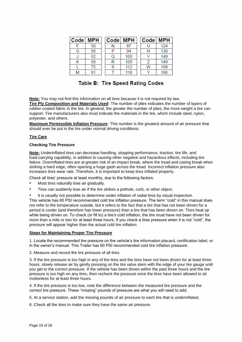
Speed Rating- The speed rating denotes the speed at which a tire is designed to be driven for extended periods of time. This does not indicate that the vehicle or rims can safely reach or maintain that speed. These ratings are listed in Table B. (The markings on the example tire diagram show M. The markings on your tire may differ.)
Page 19 of 28
Note: You may not find this information on all tires because it is not required by law.
Tire Ply Composition and Materials Used- The number of plies indicates the number of layers of
rubber-coated fabric in the tire. In general, the greater the number of plies, the more weight a tire can
support. Tire manufacturers also must indicate the materials in the tire, which include steel, nylon,
polyester, and others.
Maximum Permissible Inflation Pressure- This number is the greatest amount of air pressure that
should ever be put in the tire under normal driving conditions.
Tire Care
Checking Tire Pressure
Note: Underinflated tires can decrease handling, stopping performance, traction, tire life, and load-carrying capability, in addition to causing other negative and hazardous effects, including tire failure. Overinflated tires are at greater risk of an impact break, where the tread and casing break when striking a hard edge, often opening a huge gash across the tread. Incorrect inflation pressure also increases tires wear rate. Therefore, it is important to keep tires inflated properly.
Check all tires’ pressure at least monthly, due to the following factors:
• Most tires naturally lose air gradually.
• Tires can suddenly lose air if the tire strikes a pothole, curb, or other object.
• It is usually not possible to determine under inflation of radial tires by visual inspection.
This vehicle has 60 PSI recommended cold tire inflation pressure. The term “cold” in this manual does
not refer to the temperature outside, but it refers to the fact that a tire that has not been driven for a
period is cooler (and therefore has lower pressure) than a tire that has been driven on. Tires heat up
while being driven on. To check (or fill to) a tire’s cold inflation, the tire must have not been driven for
more than a mile or two for at least three hours. If you check a tires pressure when it is not “cold”, the
pressure will appear higher than the actual cold tire inflation.
Steps for Maintaining Proper Tire Pressure
1. Locate the recommended tire pressure on the vehicle’s tire information placard, certification label, or in the owner’s manual. This Trailer has 60 PSI recommended cold tire inflation pressure.
2. Measure and record the tire pressure of all tires.
3. If the tire pressure is too high in any of the tires and the tires have not been driven for at least three hours, slowly release air by gently pressing on the tire valve stem with the edge of your tire gauge until you get to the correct pressure. If the vehicle has been driven within the past three hours and the tire pressure is too high on any tires, then recheck the pressure once the tires have been allowed to sit motionless for at least three hours.
4. If the tire pressure is too low, note the difference between the measured tire pressure and the correct tire pressure. These “missing” pounds of pressure are what you will need to add.
5. At a service station, add the missing pounds of air pressure to each tire that is underinflated.
6. Check all the tires to make sure they have the same air pressure.

Page 20 of 28
7. If the tires’ pressure was not measured “cold”, then the pressure should be rechecked with the tires cold as soon as possible.
Tire Size
To maintain safety, only purchase new tires of the same size as the original tires. Look at the Tire and Loading Information Placard, the Specifications Chart in this manual, or the sidewall of the tire being replaced. If you have any doubt about selecting the correct size, consult a tire dealer.
Tire Tread
The tire tread provides traction that prevents your vehicle from slipping, especially if the road is wet or icy. Tires are unsafe and should be replaced when the tread is worn down to 1/16". Measure tread depth using a tread depth indicator (not included).
Tire Rotation
Every 5,000 miles the left and right tires should be switched. This will cause the tires to wear more
evenly and last longer.
Tire Balance and Alignment
The tires need to be balanced to prevent vibration when driving. This involves attaching small weights to the rim to offset small differences in rim and tire weight. The tires also need to be aligned properly. Alignment is the orientation of the tires to the road surface and their being parallel. This helps the tires to wear evenly, and provide better traction. Both tire balance and alignment require specialized equipment that is not provided with this vehicle.
Tire Repair
To properly repair a punctured tire, the hole needs to be properly plugged and patched from the inside
of the tire. Tread punctures can be repaired if they are not too large. Sidewall punctures should not be
repaired, the tire needs to be replaced if the sidewall is damaged. Tires should be removed from the
rim to be inspected before being plugged and patched. A qualified mechanic should remove the tire
from the rim, perform the repair, and remount the tire.
Vehicle Load Limit
Tire Inflation and Load Limit
The tire and loading Information Placard displays the cold tire inflation pressure and the load limit for
this vehicle. See the tire care section starting on the following page for an explanation of tire pressure
and see the Vehicle Load Limit following that for an explanation of load limit.
Page 21 of 28
Steps for Determining Correct Load Limit
1. Locate the statement “The weight of cargo should never exceed 271 kilograms or 600 pounds” on your vehicle’s placard.
2. That figure equals the available amount of cargo and luggage load capacity.
3. Determine the combined weight of luggage and cargo being loaded on the vehicle. That weight may not safely exceed the available cargo and luggage load capacity.
4. If the trailer’s load exceeds the cargo and luggage load capacity, then the trailer will be unsafe resulting in hazardous effects, such as: trailer’s tires will not be able to maintain traction properly, and stopping distance will be increased significantly.
After Each Use
Check for damaged or cracked parts on the trailer after each use, including the tire condition and pressure. Replace damaged parts before next use.
Wash off the trailer to prevent dirt and road grime from hardening on the components.
Maintenance
Tires
1. Periodic inspection and maintenance of tires and wheels are essential to towing safety, including
spare tires. Proper tire pressure affects vehicle handling and the safety of your tires. You can find the
correct tire pressure for your tow vehicle on the tire information placard.
2. Under inflation reduces the load-carrying capacity of your tow vehicle or trailer, may cause sway and control problems, and may result in overheating, causing blowouts or other tire failure.
3. Over inflation causes premature tire wear and affects the handling characteristics of the tow vehicle or trailer.
Wheel Bearings
1. EVERY 2,000 TO 3,000 MILES OF USE lubricate the Hub Assemblies with a heavy weight bearing grease, following the instructions in Hub Bearing Maintenance.
2. After each hub assembly is reassembled, tighten the castle nut until the wheel starts spinning with slight resistance. Loosen the castle nut about 1/6 turn from this point. 3. Insert a new cotter pin through the castle nut and the hole in the axle.
4. Bend the cotter pin back, locking it and the nut in place.
Hub Bearing Maintenance
If the following procedure is not adhered to, it may result in wheel locking and tire blowout, causing an automobile accident or road hazard. Whenever a hub on a new unit requires assembly (or a hub is disassembled for maintenance), the following procedures MUST be followed:
Using a suitable solvent, thoroughly clean the bearings, dust hub cap, and the rest of the parts of the hub assembly of all grease, dirt, metal shavings, or any other foreign object. The parts must be cleaned even if they are new or appear clean.
Allow all parts to dry completely.
Make sure your hands are clean and bearing packer (not supplied) is also clean.
Place fresh, clean bearing grease in the bearing packer.
With the grease-filled bearing packer in one hand and the bearing in the other, press the bearing into the grease, forcing the grease inside the slots in the bearing. Continue doing this until every

Page 22 of 28
slot in the bearing is completely full of grease.
As you finish assembling the hub, be careful not to get any dirt or debris on any part of the assembly.
Replace the dust hub cap over each bearing.
Hitch
Check the nuts, bolts, and other fasteners to ensure that the hitch remains secured to the tow vehicle
and the coupler remains secured to the trailer. The connection point may require periodic lubrication to
permit free movement of the coupler to the hitch ball.
Wiring
1. Make sure connector-plug prongs and receptacles, light bulb sockets, wire splices, and ground connections are clean and shielded from moisture. Lightly coat all electrical terminal connections with no conducting (dielectric), light waterproof grease.
2. Clean the prongs with very fine sandpaper, being careful not to damage the contact area.
3. Turn lights off, and then clean the surface deposits in the connector holes. Try to clean off only the deposits and lubricate lightly with dielectric, light waterproof grease.
Maintenance Chart The following chart serves as a basic guideline for scheduling your trailer maintenance. Maintenance
may be different based on your local conditions, type of trailer, and frequency of trailer use.
⚠CAUTION
All maintenance, service, or repairs listed in this manual are only to be attempted by a qualified service
technician.

Page 23 of 28
Troubleshooting
General Handling
1. Use the driving gear that the towing vehicle manufacturer recommends for towing.
2. Drive at moderate speeds. This will place less strain on your tow vehicle and trailer. Trailer instability (sway) is more likely to occur as speed increases. Do not exceed 55 miles per hour when towing the trailer.
3. Avoid sudden stops and starts that can cause skidding, sliding, or jack-knifing.
4. Avoid sudden steering maneuvers that might create sway or undue side force on the trailer.
5. Slow down when traveling over bumpy roads, railroad crossings, and ditches.
6. Make wider turns at curves and corners. Because your trailer’s wheels are closer to the inside of a turn than the wheels of your tow vehicle, they are more likely to hit or ride up over curbs.
7. To control swaying caused by air pressure changes and wind buffeting when larger vehicles pass from either direction, release the accelerator pedal to slow down and keep a firm grip on the steering wheel.

Page 24 of 28
Parts Diagram

Page 25 of 28
Parts List
Part Description Qty. Part Description Qty.
1 Trailer Body 1 24 Bolt (M10 x 40) 4
2 Leaf Spring 2 25 Bolt (M12 x 80) 4
3 Axle 1 26 Bolt (M10 x 70) 1
4 Hubs 2 27 Bolt (M10 x 90) 2
5 Tire 2 28 Bolt (M6 x 45) 2
6 Drawbar 1 29 Washer (10) 8
7 Coupler 1 30 Washer (6) 12
8 Safety Chain 1 31 Washer (8) 8
9 Side Running Light 2 32 Lock Nut (M6) 14
10 Left Tail Light 1 33 Lock Nut (M8) 7
11 Right Tail Light 1 34 Lock Nut (M10) 21
12 License Plate Bracket 1 35 Lock Nut (M12) 4
13L Fender L 1 36 U-Bolt (10-100x53) 4

Page 26 of 28
Part Description Qty. Part Description Qty.
13R Fender R 1 37 U-Bolt (10-85x78) 3
14 Upper Shell 1 38 Lug Nut 8
15 Bottom Shell 1 39 Rubber Pad 4
16 Hinge Bracket 2 40 Cooler Rack 1
17 Gas Spring 2 41 Mounting Plate 2
18 Snap Latch 2 42 Latch 1
19 Body Bracket 2 43 Stand 1
20 Lock Bracket 1 44 Bumper 1
21 Key 2 45 Bolt (M8 x 20) 2
22 Spring Plate 2 46 Latch Spring 1
23 Bolt (M6 x 20) 12
Replacement Parts
For replacement parts and technical questions, please call Customer Service at 1-800-222-5381.
Not all product components are available for replacement. The illustrations provided are a
convenient reference to the location and position of parts in the assembly sequence.
When ordering parts, the following information will be required: item description, item model
number, item serial number/item lot date code, and the replacement part reference number.
The distributor reserves the rights to make design changes and improvements to product lines and
manuals without notice.

Page 27 of 28
Limited Warranty
Northern Tool and Equipment Company, Inc. ("We'' or "Us'') warrants to the original purchaser only
("You'' or "Your") that the Ultra-Tow product purchased will be free from material defects in both
materials and workmanship, normal wear and tear excepted, for a period of one year from date of
purchase. The foregoing warranty is valid only if the installation and use of the product is strictly in
accordance with product instructions. There are no other warranties, express or implied, including the
warranty of merchantability or fitness for a particular purpose. If the product does not comply with this
limited warranty, Your sole and exclusive remedy is that We will, at our sole option and within a
commercially reasonable time, either replace the product or product component without charge to You
or refund the purchase price (less shipping). This limited warranty is not transferable.
Limitations on the Warranty
This limited warranty does not cover: (a) normal wear and tear; (b) damage through abuse, neglect,
misuse, or as a result of any accident or in any other manner; (c) damage from misapplication,
overloading, or improper installation; (d) improper maintenance and repair; and (e) product alteration in
any manner by anyone other than Us, with the sole exception of alterations made pursuant to product
instructions and in a workmanlike manner.
Obligations of Purchaser
You must retain Your product purchase receipt to verify date of purchase and that You are the original
purchaser. To make a warranty claim, contact Us at 1-800-222-5381, identify the product by make and
model number, and follow the claim instructions that will be provided. The product and the purchase
receipt must be provided to Us in order to process Your warranty claim. Any returned product that is
replaced or refunded by Us becomes our property. You will be responsible for return shipping costs or
costs related to Your return visit to a retail store.
Remedy Limits
Product replacement or a refund of the purchase price is Your sole remedy under this limited warranty
or any other warranty related to the product. We shall not be liable for: service or labor charges or
damage to Your property incurred in removing or replacing the product; any damages, including,
without limitation, damages to tangible personal property or personal injury, related to Your improper
use, installation, or maintenance of the product or product component; or any indirect, incidental or
consequential damages of any kind for any reason.
Assumption of Risk
You acknowledge and agree that any use of the product for any purpose other than the specified
use(s) stated in the product instructions is at Your own risk.
Governing Law
This limited warranty gives You specific legal rights, and You also may have other rights which vary
from state to state. Some states do not allow limitations or exclusions on implied warranties or
incidental or consequential damages, so the above limitations may not apply to You. This limited
warranty is governed by the laws of the State of Minnesota, without regard to rules pertaining to
conflicts of law. The state courts located in Dakota County, Minnesota shall have exclusive jurisdiction
for any disputes relating to this warranty.

Page 28 of 28
Distributed by:
Northern Tool & Equipment Company, Inc.
Burnsville, Minnesota 55306
www.northerntool.com
Made in China