tailored materials for high efficiency cidi engines ... · tailored materials for high efficiency...
TRANSCRIPT
Tailored Materials for High Efficiency CIDI Engines (Caterpillar CRADA)
Glenn Grant, PresenterYuri Hovanski
Pacific Northwest National Laboratory
M. Brad Beardsley, Mark VelizCaterpillar, Inc.
2009 DOE Hydrogen Program and Vehicle Technologies Program Annual Merit Review and Peer Evaluation Meeting,
May 18-22, 2009
This presentation does not contain any proprietary, confidential, or otherwise restricted information
pm_08_grant
Purpose of Work
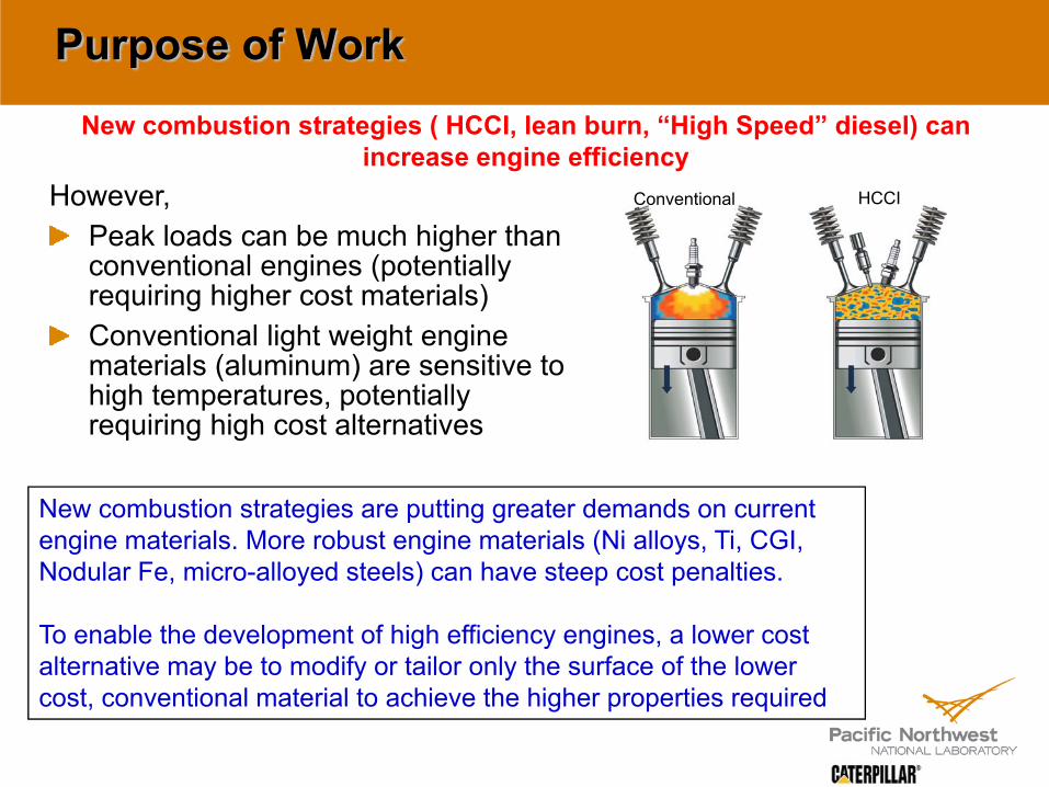
However,Peak loads can be much higher than conventional engines (potentially requiring higher cost materials)Conventional light weight engine materials (aluminum) are sensitive to high temperatures, potentially requiring high cost alternatives
New combustion strategies ( HCCI, lean burn, “High Speed” diesel) can increase engine efficiency
Conventional HCCI
New combustion strategies are putting greater demands on current engine materials. More robust engine materials (Ni alloys, Ti, CGI, Nodular Fe, micro-alloyed steels) can have steep cost penalties.
To enable the development of high efficiency engines, a lower cost alternative may be to modify or tailor only the surface of the lower cost, conventional material to achieve the higher properties required
3
Overview
Start: FY2008 - CRADA signed Nov 2007Project end date: Dec. 2010Percent complete: 25%
Fuel EfficiencyNew combustion strategies necessary for increased engine efficiency are putting higher demands on traditional engine materials. Without better materials gains can’t be realized
Thermal ManagementKeeping heat where it belongs increases thermodynamic efficiency. Better TBCs are needed
Reduced manufacturing costsEngineered surfaces on conventional materials could be lower cost option than some high performance materials.
• FY08: $375k (DOE) FY09:$340k (DOE)
• 50/50 Cost Share with Caterpillar through in-kind contribution
Timeline
Budget
Barriers
• CRADA with Caterpillar, Inc.• Steering committee made up of members
from Surface Engineering and High Temperature Materials groups within Caterpillar Tech Center
• Project lead: PNNL
Partners

Project Objectives To increase the thermal and mechanical efficiency and durability of engine materials through the development of a new surface engineering technology – Friction Stir Processing
To develop and deploy this technology on traditional (low cost) engine materials and subsystems; cast iron, alloy steels, and aluminum alloy parts
FY 2009 FocusExperimentally develop FSP in aluminum materials that are compositional analogs to the typical piston and head alloys seen in small to mid-sized CIDI engines. Quantify performance advantages at the coupon scaleDevelop Friction Stir tools and parameters that allow surface modification of steels
Technical Background - Friction Stir Processing
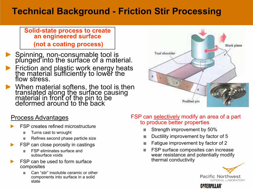
Spinning, non-consumable tool is plunged into the surface of a material. Friction and plastic work energy heats the material sufficiently to lower the flow stress.When material softens, the tool is then translated along the surface causing material in front of the pin to be deformed around to the back
Solid-state process to create an engineered surface(not a coating process)
FSP creates refined microstructureTurns cast to wroughtRefines second phase particle size
FSP can close porosity in castingsFSP eliminates surface and subsurface voids
FSP can be used to form surface composites
Can “stir” insoluble ceramic or other components into surface in a solid state
Process Advantages FSP can selectively modify an area of a part to produce better properties
Strength improvement by 50%Ductility improvement by factor of 5Fatigue improvement by factor of 2FSP surface composites can increase wear resistance and potentially modify thermal conductivity
Project Milestones
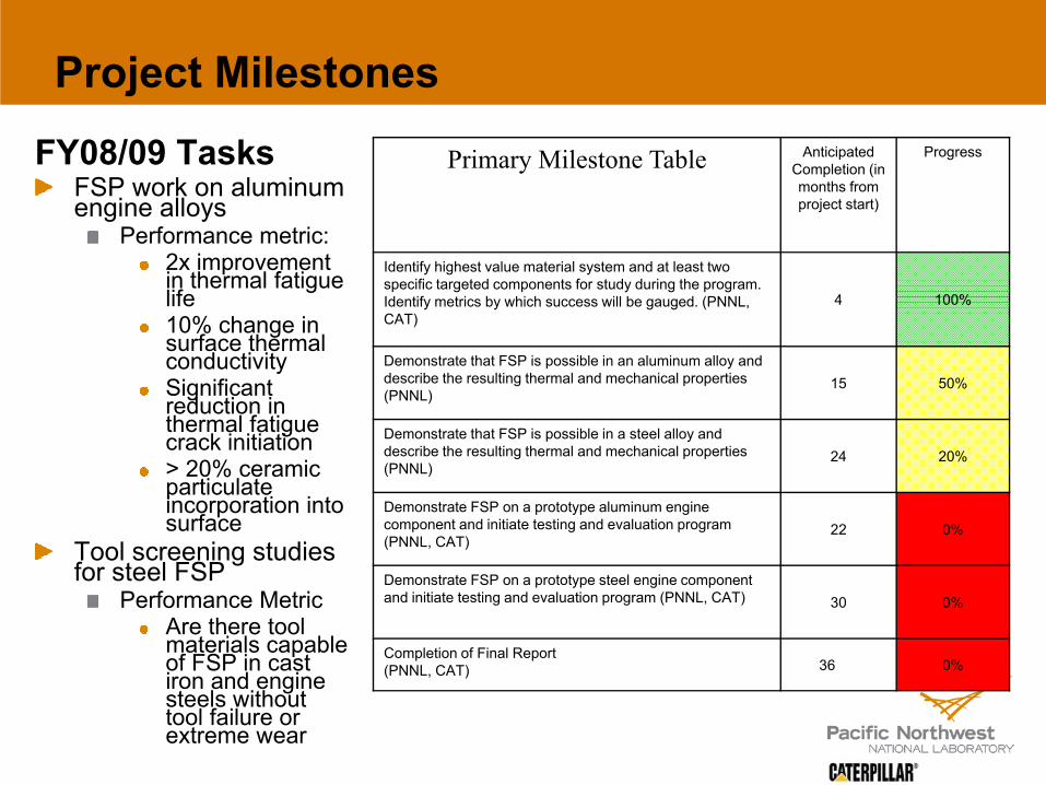
FY08/09 TasksFSP work on aluminum engine alloys
Performance metric:2x improvement in thermal fatigue life10% change in surface thermal conductivitySignificant reduction in thermal fatigue crack initiation > 20% ceramic particulate incorporation into surface
Tool screening studies for steel FSP
Performance MetricAre there tool materials capable of FSP in cast iron and engine steels without tool failure or extreme wear
Primary Milestone Table Anticipated Completion (in months from project start)
Progress
Identify highest value material system and at least two specific targeted components for study during the program. Identify metrics by which success will be gauged. (PNNL, CAT)
4 100%
Demonstrate that FSP is possible in an aluminum alloy and describe the resulting thermal and mechanical properties (PNNL)
15 50%
Demonstrate that FSP is possible in a steel alloy and describe the resulting thermal and mechanical properties (PNNL)
24 20%
Demonstrate FSP on a prototype aluminum engine component and initiate testing and evaluation program (PNNL, CAT)
22 0%
Demonstrate FSP on a prototype steel engine component and initiate testing and evaluation program (PNNL, CAT) 30 0%
Completion of Final Report(PNNL, CAT) 36 0%

Potential uses for FSP technology in heavy-duty engine environments Aluminum Materials
PistonsThermal Fatigue of bowl rim areasAluminum material temperature limits – need for thermal barrier layerHigh temp strength and fatigue resistance of Pin strap areaCostly cast-in insert for top ring
HeadsTop deck fatigueBottom deck thermal fatigue
Steel / Cast Iron MaterialsPistons
Ring groove wearThermal fatigue of bowl rimCostly forged steels (better to use cast with selective property enhancementThermal barrier layer
ValvesValve seat wear
CrankshaftsFillet fatigue enhancementOil hole fatigue enhancement
LinersPrevention of cavitationThermal resistance to allow cast iron use on higher temperature
HeadThermal fatigue enhancement on cross cutTop deck fatigueThermal resistance

Approach 1 - Increased thermal fatigue strength of piston bowl rim
Forged or cast blank prior to final machining
FSP region
After machining, bowl rim is composed of FSP nugget material
FSP region
Goal for processed region: • Increased thermal fatigue resistance• Decreased fatigue crack growth rate• Lower CTE (by addition of other components)
• Higher conductivity (by addition of other components)

Approach 2 – Increased strength and durability of top ring land and increased wear resistance of skirt
FSP regionPiston skirt
FSP regionTop ring land prior to final machining
Start with high temp alloy with better fatigue properties (hypo-eutectic?) and selectively engineer regions that need high wear resistance and strength
Stir in ceramic component and achieve high loading of Al2O3 or SiC
Goal for processed region: • Increased wear resistance• Increased hot hardness

Technical Accomplishments / Results
During 2008 the project focused on FSP in aluminum materials that are compositional analogs to the typical piston and head alloys seen in small to mid-sized CIDI engines. At this point all our work is on flat coupons.Investigations were primarily of two types:
FSP of cast hypo-eutectic aluminum with no introduction of any new component materials
FSP of eutectic Cu-Ni aluminum alloys by physically “stirring in” various quantities of carbon nanotubes and nanofibers.
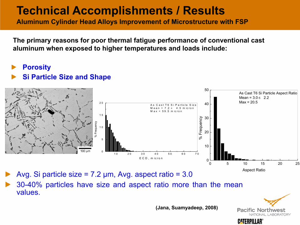
Avg. Si particle size = 7.2 µm, Avg. aspect ratio = 3.030-40% particles have size and aspect ratio more than the meanvalues.
1 0 2 0 3 0 4 0 5 0 6 0 7 00
5
1 0
1 5
2 0A s C a s t T 6 S i P a r t ic le S iz eM e a n = 7 . 2 6 4 . 5 m ic r o nM a x = 5 9 . 5 m ic r o n
% F
requ
ency
E C D , m ic r o n
0 5 10 15 20 250
10
20
30
40
50As Cast T6 Si Particle Aspect RatioMean = 3.0 6 2.2Max = 20.5
% F
requ
ency
Aspect Ratio
The primary reasons for poor thermal fatigue performance of conventional cast aluminum when exposed to higher temperatures and loads include:
(Jana, Suamyadeep, 2008)
PorositySi Particle Size and Shape
Technical Accomplishments / ResultsAluminum Cylinder Head Alloys Improvement of Microstructure with FSP

Mean particle size = 3.1 µm(reduced from 7.2 µm)Mean particle aspect ratio = 1.7(reduced from 3.0)FSP was able to refine the Siparticles by more than 50 %.Compared to as-cast condition,20-25 % of total particles wereabove mean value after FSP.(reduced from 30% to 40%)FSP was also instrumental ineliminating comparatively biggerparticles from the matrix.
0 5 10 15 20 250
10
20
30
40
50FSP T6 Si Particle SizeMean = 3.1 6 2.5 micronMax = 20.0 micron
% F
requ
ency
ECD, micron
2236/ 2.32
(a)
2236/ 2.32 T6
(b)
0 2 4 6 8 100
20
40
60
80
100FSP T6 Particle Aspect RatioMean = 1.7 6 0.7Max = 8.2
% F
requ
ency
Aspect Ratio
Technical Accomplishments / Results Aluminum Cylinder Head Alloys Improvement of Microstructure with FSP
Friction Stir Processing reduces particle size, aspect ratio and gets rid of “big” particles
(Jana, Suamyadeep, 2008)

103 104 105 106 107 1080
50
100
150
200
250
300
R = -1
Cast + T6 FSP + T6
Max
imum
Ben
ding
Stre
ss (M
Pa)
No. of Cyles to failure
Technical Accomplishments / Results
The current solution to poor fatigue performance (including thermal fatigue) is to go to expensive casting techniques to reduce porosity, or make alloy changes to higher strength alloys. FSP (selectively applied to the problem areas) may allow lower cost alloys to be used at higher stress levels for the same durability level
The microstructural changes induced by FSP lead to significant improvement in fatigue performance in the processed region
(Jana, Suamyadeep, 2008)

Technical Accomplishments / ResultsUsing FSP to “stir in” new components into piston alloys for improved bowl rim thermal fatigue
3/16 and 1/8 diameter 3013 aluminum tubes packed with Carbon nanotube / fiber plus aluminum powder mixes
Goals for Carbon nanotube FSP:• Low CTE• High thermal conductivity• May get high strength too
Material Modulus CTE Conductivity
Aluminum 80 GPa 25 μm/m°C 180 W/m-K
SiC 410 GPa 4.4 μm/m°C 150 W/m-K
Al2O3 370 GPa 8.5 μm/m°C 13 W/m-K
Carbon Nanotubes
>600 GPa Very low to 0 > 1000 W/m-K
Important for thermal fatigue
We were successful at stirring-in multiwall carbon nanotubes and nanofibers into the substrate

Cross section of Stir Zone
Adv. side
Technical Accomplishments / ResultsUsing FSP to “stir in” new components for improved bowl rim thermal fatigueCarbon nanotubes
Carbon Nanotube filled tubes are completely consumed by the stir toolNo volumetric defect – no holesNanotubes are mixed into aluminum matrix
Next stepsEvaluate these regions for thermal and mechanical performance
Stir tool used to incorporate new phases into the surface

Technical Accomplishments / Results Summary
Demonstrated significant fatigue improvement with FSP as applied to alloys used commonly in cylinder headsDeveloped process parameters necessary to product defect free processed zones in aluminum piston alloys, and successfully incorporated nanofibers and multiwall nanotubes into the surface of cast plates
Began development of necessary tools and parameters to FSP steels
Developed FSP machine mounted induction heating equipment to enable FSP in steels and cast iron materials, and to allow for study of in-situ heat treatment and microstructure control for improved high temp. properties
Aluminum
FSP Region
As Cast
High-load FSP machine at PNNL
Steel
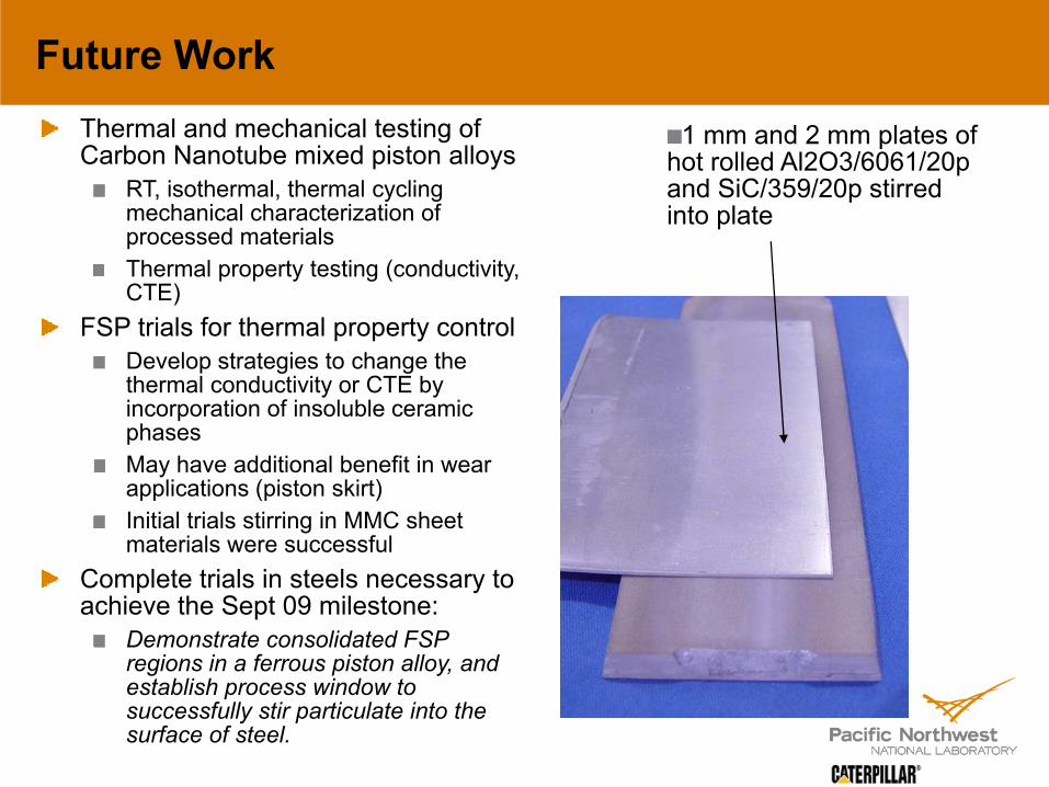
Future WorkThermal and mechanical testing of Carbon Nanotube mixed piston alloys
RT, isothermal, thermal cycling mechanical characterization of processed materialsThermal property testing (conductivity, CTE)
FSP trials for thermal property controlDevelop strategies to change the thermal conductivity or CTE by incorporation of insoluble ceramic phases May have additional benefit in wear applications (piston skirt)Initial trials stirring in MMC sheet materials were successful
Complete trials in steels necessary to achieve the Sept 09 milestone:
Demonstrate consolidated FSP regions in a ferrous piston alloy, and establish process window to successfully stir particulate into the surface of steel.
1 mm and 2 mm plates of hot rolled Al2O3/6061/20p and SiC/359/20p stirred into plate

Summary
Friction Stir Processing (FSP) is a new surface engineering technology that has the opportunity to produce tailored, high performance surfaces on low-cost, conventional engine materials
Opportunities exist for using the process to enable new combustion processes, (HCCI and others) that can significantly increase the fuel efficiency of conventional gas and CIDI engines
The project will systematically characterize the effects of FSP on materials to increase high temperature strength, increase durability of engine components (pistons, liners, cylinder heads), and potentially modify the thermal conductivity to increase thermal efficiency
The project is a cost-shared collaboration between DOE/PNNL and Caterpillar, Inc., providing immediate opportunity to deploy new technology in a company that is a market leader in engine manufacturing
Project work began in FY08 with investigations into aluminum alloy FSP with the specific target of increased mechanical and thermal properties of materials anticipated in mid-size CIDI engines