tamboli, roopak r., cserkaszky, aron, kara, peter a
TRANSCRIPT

© 2018 IEEE. Personal use of this material is permitted. Permission from IEEE must be obtained for all other uses, in any current or future media, including reprinting/republishing this material for advertising or promotional purposes, creating new collective works, for resale or redistribution to servers or lists, or reuse of any copyrighted component of this work in other works.
Tamboli, Roopak R., Cserkaszky, Aron, Kara, Peter A., Barsi, Attila and Martini, Maria G. (2018) Objective quality evaluation of an angularly-continuous light-field format. In 2018 International Conference on 3D Immersion (IC3D) : proceedings. Piscataway : IEEE. ISSN (2379-1780), ISBN: 9781538675908.
https://doi.org/10.1109/IC3D.2018.8657876

OBJECTIVE QUALITY EVALUATION OF ANANGULARLY-CONTINUOUS LIGHT-FIELD FORMAT
Roopak R. Tamboli∗,†, Aron Cserkaszky∗, Peter A. Kara∗,‡,§, Attila Barsi∗, Maria G. Martini‡
∗Holografika, Budapest, HungaryEmail: {r.tamboli, a.cserkaszky, a.barsi}@holografika.com
†Indian Institute of Technology Hyderabad, Kandi, Sangareddy, IndiaEmail: [email protected]
‡WMN Research Group, Kingston University, UKEmail: {p.kara, m.martini}@kingston.ac.uk
§Budapest University of Technology and Economics, Budapest, HungaryEmail: [email protected]
ABSTRACT
With the rapid advances in light-field display and camera tech-nology, research in light-field content creation, visualization,coding and quality assessment has gained momentum. Whilelight-field cameras are already available to the consumer, light-field displays need to overcome several obstacles in order tobecome a commonplace. One of these challenges is the un-availability of a light-field visualization format which can beused across various light-field displays. Existing light-fieldrepresentations are optimized for specific displays and con-verting them for visualization on a different display is a com-putationally expensive operation, often resulting in the degra-dation of perceptual quality. To this end, an intermediate,display-independent and angularly-continuous light-field rep-resentation format has been proposed recently, targeted to-wards large-field-of-view light-field displays. In this paper,we evaluate the said data format in terms of degradation in ob-jective quality under three compression methods. We foundthat, while offering display-independence, the intermediatelight-field format maintains the same objective quality in gen-eral and achieves higher objective quality in some cases com-pared to the conventional linear camera representation.
Index Terms— Light-field, visualization format, objec-tive quality assessment
1. INTRODUCTION
Light-field (LF) capture and visualization has progressed sig-nificantly in recent years [1]. The current generation of LF
The work in this paper was funded from the European Union’s Horizon2020 research and innovation program under the Marie Sklodowska-Curiegrant agreements No 676401, European Training Network on Full ParallaxImaging and No 643072, Network QoE-Net.
displays are used mostly in the industry and research institu-tions. On the other hand, LF cameras are already available onthe consumer market. These cameras capture narrow-baselineLF images with their microlense-based optics 1. Such formatsare not suitable for wide-baseline LF displays.
Wide-baseline LF displays offer life-like immersive expe-rience via continuous motion parallax. In order to do so, suchdisplays need a large amount of input data, often capturedusing a multi-camera array [2]. The physical size of the cam-eras limits how densely they can be arranged. Furthermore,deploying a dense camera rig is economically and technolog-ically prohibitive. In practice, multi-view content is acquiredusing sparse camera arrays, followed by view interpolation. Acomputationally expensive conversion of the captured LF tothe display-specific LF is then performed. The quality of suchconverted LF depends on the closeness between the samplingof the ray space of the two LFs. Thus, LF data optimizedfor a certain display cannot be used on another display with-out several inefficiencies in conversion. In future applicationsof LF — such as dynamic adaptive video streaming [3] andteleconferencing [4] — low latency requirements necessitatedisplay-specific LF mapping to be performed at the acqui-sition side as opposed to the display side [5]. It is clearlynot possible for the acquisition side to convert and transmitdisplay-specific LF for all available display types due to hugeamounts of data. In such situations, the availability of LF rep-resentation formats that are oblivious to the acquisition side— as well as the display side — becomes a necessity. To thisend, Damghanian et al. recently proposed a camera-agnosticformat and processing for LF data [6], and Cserkaszky et al.focused on wide-baseline displays and proposed an angularly-continuous intermediate LF representation [5].
1Stanford light field file format,http://graphics.stanford.edu/software/lightpack/lightpack.html

(a) Source stimulus A (b) Source stimulus B (c) Source stimulus C (d) Source stimulus D
Fig. 1: 2D views of the 3D models used to generate stimuli in ‘s-t-phi’ format and perspective camera format.
In this paper, we evaluate the intermediate LF format pro-posed by Cserkaszky et al. [5]. Specifically, the said formatwas compared with perspective camera representation undervarious compression schemes and a few objective quality met-rics. It was observed that the objective quality values for theintermediate LF format were the same as those for the per-spective camera format. In some cases, the intermediate for-mat offered higher objective quality values. Thus, display-independence using the intermediate format is achieved with-out any compromise in objective quality values when com-pared to the conventional format.
The rest of this paper is organized as follows: Section 2presents the related work on LF representation formats. Thedataset, compression methods and objective quality metricsused in this paper are described in Section 3. Results of thisstudy are presented in Section 4. A discussion is provided inSection 5. Section 6 concludes the paper.
2. RELATED WORK
Existing LF formats are either designed to represent denseand uniformly sampled LFs or they contain a set of imagescaptured from different positions by perspective cameras alongwith calibration parameters [5][7]. Narrow-baseline LF datacan be captured using plenoptic cameras. On the other hand,wide-baseline LF content needs to be captured using either asingle moving camera (restricted to static scenes) or an arrayof cameras. A wide variety of datasets have been used as LFcontent. In a recent call for evaluations of super multi-view(SMV) and free-viewpoint content, several camera configu-rations to capture multiview data were proposed, such as 1Dlinear arrangement, 2D or full-parallax arrangement, conver-gent arc setups, etc. [8].
Both the aforementioned regimes of LF acquisition gen-erate a huge amount of data and therefore necessitate com-pression. Existing LF compression schemes generally adaptintra- and inter-frame coding [9]. For example, Ahmed et al.treated views from multi-camera system as frames of a mul-tiview sequence, and compressed them using the Multiviewextension of High Efficiency Video Coding [10]. Similarly,Guo et al. proposed a two-pass encoding system for pseudo-temporal sequence of LF data captured using plenoptic cam-eras [11]. While LF compression has gained significamt at-
tention, research towards an LF representation that does notadhere to a specific LF camera or LF display is in its infancy.
Recently, Damghanian et al. proposed a camera-agnosticformat and processing for LF data [6]. Their LF processingpipeline decouples the LF capture system from LF storageand processing. The feasibility of their two camera-agnosticdata formats — which store geometry and color content of theLF data, respectively — was demonstrated using a depth ex-traction algorithm, applied to LF data captured by four typesof camera setups.
Pertaining to wide-baseline LF displays, Cserkaszky et al.recently proposed a novel parameterization of LF data [5].This representation lies between the source content (e.g., per-spective camera images) and the final LF slices (optical mod-ule images). The format only assumes that the screen of thedisplay is approximately flat, and the rays it can emit have asymmetry in the angular domain. The format describes the4D LF with two spatial coordinates (that indicate the start po-sitions of the rays), and two angular coordinates (that give thedirections of the rays). The header of the format contains theproperties of the LF: the number of pixels and their physicalsize in each spatial dimension, the field of view (FOV) andthe number of angular views in each angular dimension. Thesaid dimensions are denoted with s, t, φ and θ [12]. Fromthe intermediate representation, it is clearly possible to makea geometry-specific conversion for a specific LF display. Dueto the horizontal-parallax-only (HPO) nature of the existing,commercially available LF displays, Cserkaszky et al. referto their novel format as the ‘s-t-phi format’, because the sec-ond angle θ is not required in this case. Since the representa-tion provides one image per angle, it is also referred to as an‘angularly-continuous light-field format’.
3. EXPERIMENTS
We begin with the description of the investigated LF con-tent, rendered in both perspective camera format and s-t-phiformat. Next, we provide details of the three compressionschemes used in this study. Finally, we describe the 2D im-age quality metrics, as well as the 3D objective quality metricused in this paper.

Stimulus A Stimulus B Stimulus C Stimulus DJP
EG
5 25 50 75 100
Quality Parameter
25
30
35
40
45
50
55
PS
NR
s-t-phi
perspective
5 25 50 75 100
Quality Parameter
25
30
35
40
45
50
55
PS
NR
s-t-phi
perspective
5 25 50 75 100
Quality Parameter
25
30
35
40
45
50
55
PS
NR
s-t-phi
perspective
5 25 50 75 100
Quality Parameter
25
30
35
40
45
50
55
PS
NR
s-t-phi
perspective
JPE
G20
00
5 25 50 75 100
Compression Ratio
25
30
35
40
45
50
55
PS
NR
s-t-phi
perspective
5 25 50 75 100
Compression Ratio
25
30
35
40
45
50
55
PS
NR
s-t-phi
perspective
5 25 50 75 100
Compression Ratio
25
30
35
40
45
50
55
PS
NR
s-t-phi
perspective
5 25 50 75 100
Compression Ratio
25
30
35
40
45
50
55
PS
NR
s-t-phi
perspective
Web
P
5 25 50 75 100
Quality Parameter
25
30
35
40
45
50
55
PS
NR
s-t-phi
perspective
5 25 50 75 100
Quality Parameter
25
30
35
40
45
50
55
PS
NR
s-t-phi
perspective
5 25 50 75 100
Quality Parameter
25
30
35
40
45
50
55
PS
NR
s-t-phi
perspective
5 25 50 75 100
Quality Parameter
25
30
35
40
45
50
55
PS
NR
s-t-phi
perspective
Fig. 2: 2D quality assessment using PSNR metric.
3.1. Investigated light-field content
In this section, we describe the LF content chosen for com-pression experiments [13]. A subset of this content was alsoused to derive stimuli for the expert evaluation of the s-t-phiformat by Cserkaszky et al.[12]. The 2D views of the 3Dmodels used to generate the stimuli are shown in Figure 1.In this work, for both the perspective camera format and thes-t-phi format, 101 images were rendered, corresponding tothe 101 linearly arranged cameras and the 101 angles, respec-tively. The number of images/angles were chosen in orderto provide an angular resolution of 2 views per degree (alsodenoted as an angular resolution of 0.5 degree) for an HPOdisplay calibrated for 50◦ FOV.
Stimulus A and B were complex mathematical bodies withlarge depths2, stimulus C and D were laser-scanned statueswith smaller depths3. The difference between A and B wasthat while A (polyhedron with 972 faces) had a detailed, uni-form grid on the front (closest to the observer), stimulus B(structure of 120 regular dodecahedra) had a simple, smoothsurface segment on the side of the object. In general, both
2George W. Harts Rapid Prototyping Web Page,www.georgehart.com/rp/rp.html
3Jotero.com 3D-Scan and 3D Measurement,forum.jotero.com/viewtopic.php?t=3
A and B suffer significant penalties in the perceived visualquality, even at the slightest compression level.
3.2. Investigated image compression methods
We now describe the three compression methods used in thiswork. Each source stimulus — rendered in both s-t-phi for-mat and perspective camera format — was compressed usingJPEG4, JPEG20005 and WebP6 compression methods at 20quality/compression levels. The stimuli were compressed be-fore the display-specific LF conversion. Thus, the 4 sourcestimuli compressed using the 3 compression methods at 20quality levels resulted in 240 sets of 101 images. Includingthe 4 uncompressed sets, the total number of sets amountedto 244. The value of ‘Quality Parameter’ (or CompressionRatio in case of JPEG2000) was varied from 5 to 100 in stepsof 5. The JPEG and JPEG2000 compressions were achievedin MATLAB. For WebP compression, we built the ‘cwebp’and ‘dwebp’ tools from the WebP codec v0.6.1.
Each compressed image was compared with the corre-sponding reference image using the objective metrics described
4https://jpeg.org/jpeg/index.html5https://jpeg.org/jpeg2000/index.html6https://developers.google.com/speed/webp/

Stimulus A Stimulus B Stimulus C Stimulus DJP
EG
5 25 50 75 100
Quality Parameter
0.96
0.97
0.98
0.99
1
MS
-SS
IM
s-t-phi
perspective
5 25 50 75 100
Quality Parameter
0.96
0.97
0.98
0.99
1
MS
-SS
IM
s-t-phi
perspective
5 25 50 75 100
Quality Parameter
0.96
0.97
0.98
0.99
1
MS
-SS
IM
s-t-phi
perspective
5 25 50 75 100
Quality Parameter
0.96
0.97
0.98
0.99
1
MS
-SS
IM
s-t-phi
perspective
JPE
G20
00
5 25 50 75 100
Compression Ratio
0.96
0.97
0.98
0.99
1
MS
-SS
IM
s-t-phi
perspective
5 25 50 75 100
Compression Ratio
0.96
0.97
0.98
0.99
1
MS
-SS
IM
s-t-phi
perspective
5 25 50 75 100
Compression Ratio
0.96
0.97
0.98
0.99
1
MS
-SS
IM
s-t-phi
perspective
5 25 50 75 100
Compression Ratio
0.96
0.97
0.98
0.99
1
MS
-SS
IM
s-t-phi
perspective
Web
P
5 25 50 75 100
Quality Parameter
0.96
0.97
0.98
0.99
1
MS
-SS
IM
s-t-phi
perspective
5 25 50 75 100
Quality Parameter
0.96
0.97
0.98
0.99
1
MS
-SS
IM
s-t-phi
perspective
5 25 50 75 100
Quality Parameter
0.96
0.97
0.98
0.99
1
MS
-SS
IM
s-t-phi
perspective
5 25 50 75 100
Quality Parameter
0.96
0.97
0.98
0.99
1
MS
-SS
IM
s-t-phi
perspective
Fig. 3: 2D quality assessment using MS-SSIM metric.
in Section 3.3. A static 3D view on a LF display is composedof a set of images in our experiment. Therefore, an averageof the per-image quality values was considered as the qualityof the 3D view, computed in a full-reference (FR) setting.
3.3. 2D objective quality metrics
The FR 2D image quality metrics used in this work can beclassified into the following categories: pixel-based, structure-based and scene-statistics-based. The metrics selected fromthese categories were Peak Signal-to-Noise Ratio (PSNR),Multi-Scale Structural SIMilarity (MS-SSIM) [14], FeatureSimilarity Index Measure (FSIM) [15] and Information Fi-delity Criterion (IFC) [16], respectively.
MS-SSIM relies on the ability of the human visual system(HVS) to extract structural information from a scene and as-sesses image quality based on the degradation of structural in-formation. FSIM is based on two components. The first com-ponent, termed as phase congruency, is a dimensionless mea-sure of the significance of local structure. The second com-ponent, called the image gradient magnitude, accounts for thecontrast information. IFC relies on natural scene statistics andassesses the perceptual quality by quantifying the mutual in-formation between the reference and the distorted images.
3.4. 3D objective quality metric
We now briefly explain the FR 3D objective quality metricused in this paper [17]. The metric — considering the spatio-angular nature of the LF content — evaluates the spatial andangular quality scores of a 3D perspective visualized on a LFdisplay, and then pools them into a 3D quality score using apooling parameter.
The spatial quality score Q2D involves steerable pyramiddecomposition of each of the constituent image of a 3D view,followed by fitting an univariate generalized Gaussian distri-bution (UGGD) on the coefficients. A feature vector corre-sponding to a 3D view is formed by stacking the parametersof UGGD for all the constituent images. Then, the spatialquality score Q2D is the distance between a feature vector of areference 3D view and a feature vector of a distorted 3D view,where each constituent image is distorted (compressed).
The angular quality score Qθ finds structural similaritybetween optical flow arrays computed for a pristine and a dis-torted 3D view. Optical flow is computed between succes-sive constituent images of a 3D view. The difference betweenan optical flow array for a distorted 3D view and the corre-sponding reference optical flow array indicates disturbancesin angular continuity, which can be measured by any objec-tive metric from the class of structural similarity measures.
Stimulus A Stimulus B Stimulus C Stimulus DJP
EG
5 25 50 75 100
Quality Parameter
0.88
0.9
0.92
0.94
0.96
0.98
1
FS
IM
s-t-phi
perspective
5 25 50 75 100
Quality Parameter
0.88
0.9
0.92
0.94
0.96
0.98
1
FS
IM
s-t-phi
perspective
5 25 50 75 100
Quality Parameter
0.88
0.9
0.92
0.94
0.96
0.98
1
FS
IM
s-t-phi
perspective
5 25 50 75 100
Quality Parameter
0.88
0.9
0.92
0.94
0.96
0.98
1
FS
IM
s-t-phi
perspective
JPE
G20
00
5 25 50 75 100
Compression Ratio
0.88
0.9
0.92
0.94
0.96
0.98
1
FS
IM
s-t-phi
perspective
5 25 50 75 100
Compression Ratio
0.88
0.9
0.92
0.94
0.96
0.98
1
FS
IM
s-t-phi
perspective
5 25 50 75 100
Compression Ratio
0.88
0.9
0.92
0.94
0.96
0.98
1
FS
IM
s-t-phi
perspective
5 25 50 75 100
Compression Ratio
0.88
0.9
0.92
0.94
0.96
0.98
1
FS
IM
s-t-phi
perspective
Web
P
5 25 50 75 100
Quality Parameter
0.88
0.9
0.92
0.94
0.96
0.98
1
FS
IM
s-t-phi
perspective
5 25 50 75 100
Quality Parameter
0.88
0.9
0.92
0.94
0.96
0.98
1
FS
IM
s-t-phi
perspective
5 25 50 75 100
Quality Parameter
0.88
0.9
0.92
0.94
0.96
0.98
1
FS
IM
s-t-phi
perspective
5 25 50 75 100
Quality Parameter
0.88
0.9
0.92
0.94
0.96
0.98
1
FS
IM
s-t-phi
perspective
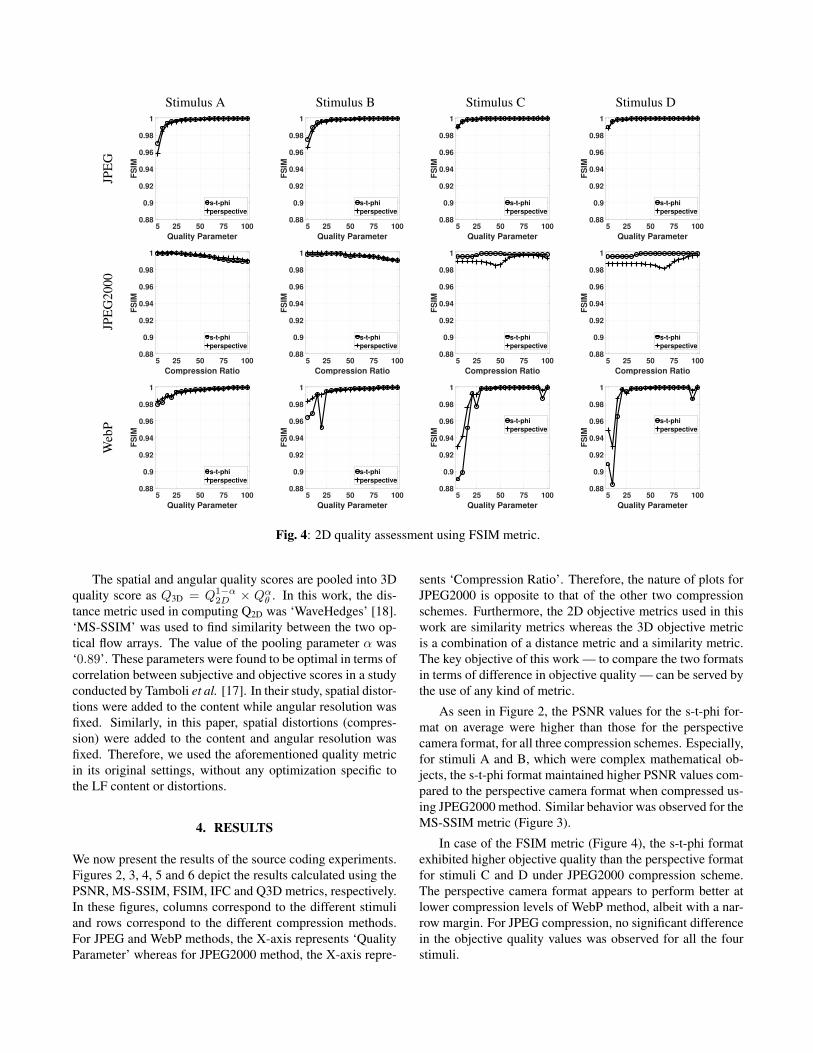
Fig. 4: 2D quality assessment using FSIM metric.
The spatial and angular quality scores are pooled into 3Dquality score as Q3D = Q1−α
2D × Qαθ . In this work, the dis-tance metric used in computing Q2D was ‘WaveHedges’ [18].‘MS-SSIM’ was used to find similarity between the two op-tical flow arrays. The value of the pooling parameter α was‘0.89’. These parameters were found to be optimal in terms ofcorrelation between subjective and objective scores in a studyconducted by Tamboli et al. [17]. In their study, spatial distor-tions were added to the content while angular resolution wasfixed. Similarly, in this paper, spatial distortions (compres-sion) were added to the content and angular resolution wasfixed. Therefore, we used the aforementioned quality metricin its original settings, without any optimization specific tothe LF content or distortions.
4. RESULTS
We now present the results of the source coding experiments.Figures 2, 3, 4, 5 and 6 depict the results calculated using thePSNR, MS-SSIM, FSIM, IFC and Q3D metrics, respectively.In these figures, columns correspond to the different stimuliand rows correspond to the different compression methods.For JPEG and WebP methods, the X-axis represents ‘QualityParameter’ whereas for JPEG2000 method, the X-axis repre-
sents ‘Compression Ratio’. Therefore, the nature of plots forJPEG2000 is opposite to that of the other two compressionschemes. Furthermore, the 2D objective metrics used in thiswork are similarity metrics whereas the 3D objective metricis a combination of a distance metric and a similarity metric.The key objective of this work — to compare the two formatsin terms of difference in objective quality — can be served bythe use of any kind of metric.
As seen in Figure 2, the PSNR values for the s-t-phi for-mat on average were higher than those for the perspectivecamera format, for all three compression schemes. Especially,for stimuli A and B, which were complex mathematical ob-jects, the s-t-phi format maintained higher PSNR values com-pared to the perspective camera format when compressed us-ing JPEG2000 method. Similar behavior was observed for theMS-SSIM metric (Figure 3).
In case of the FSIM metric (Figure 4), the s-t-phi formatexhibited higher objective quality than the perspective formatfor stimuli C and D under JPEG2000 compression scheme.The perspective camera format appears to perform better atlower compression levels of WebP method, albeit with a nar-row margin. For JPEG compression, no significant differencein the objective quality values was observed for all the fourstimuli.

Stimulus A Stimulus B Stimulus C Stimulus DJP
EG
5 25 50 75 100
Quality Parameter
0
2
4
6
8
10
IFC
s-t-phi
perspective
5 25 50 75 100
Quality Parameter
0
2
4
6
8
10
IFC
s-t-phi
perspective
5 25 50 75 100
Quality Parameter
0
2
4
6
8
10
IFC
s-t-phi
perspective
5 25 50 75 100
Quality Parameter
0
2
4
6
8
10
IFC
s-t-phi
perspective
JPE
G20
00
5 25 50 75 100
Compression Ratio
0
2
4
6
8
10
IFC
s-t-phi
perspective
5 25 50 75 100
Compression Ratio
0
2
4
6
8
10
IFC
s-t-phi
perspective
5 25 50 75 100
Compression Ratio
0
2
4
6
8
10
IFC
s-t-phi
perspective
5 25 50 75 100
Compression Ratio
0
2
4
6
8
10
IFC
s-t-phi
perspective
Web
P
5 25 50 75 100
Quality Parameter
0
2
4
6
8
10
IFC
s-t-phi
perspective
5 25 50 75 100
Quality Parameter
0
2
4
6
8
10
IFC
s-t-phi
perspective
5 25 50 75 100
Quality Parameter
0
2
4
6
8
10
IFC
s-t-phi
perspective
5 25 50 75 100
Quality Parameter
0
2
4
6
8
10
IFC
s-t-phi
perspective
Fig. 5: 2D quality assessment using IFC metric.
The results for the IFC metric are shown in Figure 5. Theperspective camera format was found to be better for stim-uli A and B under JPEG and WebP compression methods.Nevertheless, the objective quality values were very close athigher compression levels for both the formats. In the remain-ing cases, the differences in objective quality values were notsignificant.
It should be noted that in the results discussed above, thequality of 3D content was computed as the average of qualityvalues for constituent 2D images. This assumption ignoresthe fact that the viewers’ 3D experience is affected by spa-tial as well as angular properties of the content presented. Tothis end, we used a FR 3D objective quality metric, describedearlier in Section 3.4. Results for the final 3D quality scoreQ3D are shown in Figure 6. No significant difference wasobserved between two formats in terms of objective qualityvalue. For stimuli A, B and D, variation in Q3D scores wasvery small, whereas for stimulus C, Q3D scores varied signif-icantly. This can be attributed to the fact that stimulus C haslarge depth variations compared to other three stimuli [19].Also, the absence of explicit angular distortions may have re-sulted in low variations in Q3D, as the angular quality scorehas higher weight during the pooling operation. The spikein Q3D value at quality parameter value of 95 for stimulus
C under WebP compression arose due to the artifacts intro-duced by the ‘dwebp’ tool. The said tool was used to convert‘webp’ images to ‘png’ format images for computations inMATLAB. This anomaly was observed in all images gener-ated for stimuli C and D, in both representation formats, evenwith the newer versions of the ‘dwebp’ tool.
The range of values taken by Q2D, Qθ and Q3D were foundto be [16.01, 1668.31], [1.36, 1.41] and [1.85, 3.06], respec-tively. It was found that the minor differences that exist insome cases were due to large differences in correspondingspatial quality scores Q2D. Indeed, computing the element-wise absolute differences in the Q2D values, followed by com-puting variances across the quality parameter values/ com-pression ratios revealed that the variances were of the order105. Among the three compression methods, variances werehigh for the JPEG2000 method. Across the stimuli, althoughno clear pattern was observed, variances of Q2D values forstimuli C and D were high in general.
On the other hand, the angular quality scores Qθ were notvery different. The variances of the differences in angularquality scores Qθ of the two LF formats — calculated sepa-rately across the stimuli, across the compression methods, aswell as across the quality parameter values/ compression ra-tios — were of the order 10−3. Since the metric was used

Stimulus A Stimulus B Stimulus C Stimulus DJP
EG
5 25 50 75 100
Quality Parameter
1.8
2
2.2
2.4
2.6
2.8
3Q
3D
s-t-phi
perspective
5 25 50 75 100
Quality Parameter
1.8
2
2.2
2.4
2.6
2.8
3
Q3D
s-t-phi
perspective
5 25 50 75 100
Quality Parameter
1.8
2
2.2
2.4
2.6
2.8
3
Q3D
s-t-phi
perspective
5 25 50 75 100
Quality Parameter
1.8
2
2.2
2.4
2.6
2.8
3
Q3D
s-t-phi
perspective
JPE
G20
00
5 25 50 75 100
Compression Ratio
1.8
2
2.2
2.4
2.6
2.8
3
Q3D
s-t-phi
perspective
5 25 50 75 100
Compression Ratio
1.8
2
2.2
2.4
2.6
2.8
3
Q3D
s-t-phi
perspective
5 25 50 75 100
Compression Ratio
1.8
2
2.2
2.4
2.6
2.8
3
Q3D
s-t-phi
perspective
5 25 50 75 100
Compression Ratio
1.8
2
2.2
2.4
2.6
2.8
3
Q3D
s-t-phi
perspective
Web
P
5 25 50 75 100
Quality Parameter
1.8
2
2.2
2.4
2.6
2.8
3
Q3D
s-t-phi
perspective
5 25 50 75 100
Quality Parameter
1.8
2
2.2
2.4
2.6
2.8
3
Q3D
s-t-phi
perspective
5 25 50 75 100
Quality Parameter
1.8
2
2.2
2.4
2.6
2.8
3
Q3D
s-t-phi
perspective
5 25 50 75 100
Quality Parameter
1.8
2
2.2
2.4
2.6
2.8
3
Q3D
s-t-phi
perspective
Fig. 6: 3D quality assessment using Q3D metric.
with its original settings, the angular quality scores receivedhigher weight, which resulted in a minuscule difference in theoverall 3D quality score.
5. DISCUSSION
The results presented in Section 4 corroborate with the obser-vations made by Cserkaszky et al. in their expert evaluationstudy of the proposed s-t-phi format [12]. Specifically, thestimuli rendered in s-t-phi format were found to be better thanthose rendered in perspective camera format, for low angularresolutions. On the other hand, for sufficient angular reso-lutions, both formats were found to provide similar percep-tual experience. Their subjective tests were conducted on theHoloVizio C80 light-field cinema system 7. In this paper, thecontent was rendered at a recommended angular resolutionof 2 views per degree [13]. Therefore, although no explicitangular distortions were studied in this paper, the objectiveresults can be qualitatively compared to the perceptual qual-ity of stimuli rendered at sufficient or high angular resolutionsused in the aforementioned expert evaluation study.
7HoloVizio C80 light-field cinema system,http://holografika.com/c80-glasses-free-3d-cinema/
The FR 3D objective quality metric used in this workwas found to be a good indicator of perceived quality on alarge LF display in an earlier work of Tamboli et al. [17].Specifically, certain spatial distortions were added to multi-camera datasets before the display-specific LF conversion andthe objective quality assessment was performed. The objec-tive scores were found to correlate well with subjective scoreobtained through a test conducted on Holografika’s HV721RCdisplay 8. In this paper, a similar study was conducted whereonly spatial distortions (compression artifacts) were introducedto the content without any display-specific LF conversion.Therefore, we believe that, even in this case, the objectivequality score Q3D provides a good estimate of perceptual ex-perience if the contents were to be visualized on a LF display.
6. CONCLUSION
In this paper, we evaluated objective quality for light-fielddatasets rendered in a novel intermediate format, as well asin the conventional perspective camera format. The datasetswere compressed using three distinct compression methods
8HoloVizio 721RC,http://www.archive.holografika.com/Products/HoloVizio-721RC.html

and full-reference quality assessment was performed using2D and 3D quality metrics. It was observed that the proposeds-t-phi format retains objective quality levels at par with theperspective camera format. In some cases, the s-t-phi for-mat was found to be better. Thus, the intermediate light-fieldrepresentation offers several advantages over the conventionalformat [5], without any compromise in objective quality asobserved in the experiments carried out in this paper. In thefuture, we plan to evaluate this format extensively via sub-jective and objective tests, with combinations of spatial andangular distortions. We also plan to explore use cases involv-ing light-field video and its coding with the s-t-phi format.
7. REFERENCES
[1] C. Guillemot and R. Farrugia, “Light field imageprocessing: overview and research issues,” MMTCCommunications-Frontiers, vol. 12, no. 4, 2017.
[2] M. Domanski, T. Grajek, C. Conti, C. J. Debono, S. M.de Faria, P. Kovacs, L. F. Lucas, P. Nunes, C. Perra,N. M. Rodrigues et al., “Emerging imaging technolo-gies: trends and challenges,” in 3D Visual Content Cre-ation, Coding and Delivery. Springer, 2019, pp. 5–39.
[3] P. A. Kara, A. Cserkaszky, M. G. Martini, A. Barsi,L. Bokor, and T. Balogh, “Evaluation of the concept ofdynamic adaptive streaming of light field video,” IEEETransactions on Broadcasting, vol. 64, no. 2, pp. 407–421, 2018.
[4] A. Cserkaszky, A. Barsi, Z. Nagy, G. Puhr, T. Balogh,and P. A. Kara, “Real-time light-field 3D telepresence,”in 7th European Workshop on Visual Information Pro-cessing (EUVIP), 2018.
[5] A. Cserkaszky, A. Barsi, P. A. Kara, and M. G. Mar-tini, “Towards display-independent light-field formats,”in International Conference on 3D Immersion (IC3D),2017.
[6] M. Damghanian, P. Kerbiriou, V. Drazic, D. Doyen, andL. Blond, “Camera-agnostic format and processing forlight-field data,” in IEEE International Conference onMultimedia Expo Workshops (ICMEW), 2017, pp. 7–12.
[7] T. Ebrahimi, S. Foessel, F. Pereira, and P. Schelkens,“JPEG pleno: toward an efficient representation of vi-sual reality,” IEEE MultiMedia, vol. 23, no. 4, pp. 14–20, 2016.
[8] “MPEG-I visual test material summary, ISO/IECJTC1/SC29/WG11 MPEG2016/N16731,”https://mpeg.chiariglione.org/sites/default/files/files/standards/parts/docs/W16731%20MPEG-I%20phase%202%20test%20material.docx,Accessed: Sept. 2018.
[9] I. Viola, M. Rerabek, T. Bruylants, P. Schelkens,F. Pereira, and T. Ebrahimi, “Objective and subjectiveevaluation of light field image compression algorithms,”in Picture Coding Symposium (PCS), 2016.
[10] W. Ahmad, M. Sjostrom, and R. Olsson, “Compres-sion scheme for sparsely sampled light field data basedon pseudo multi-view sequences,” in Optics, Photonics,and Digital Technologies for Imaging Applications V,2018.
[11] B. Guo, J. Wen, and Y. Han, “Two-pass light field im-age compression for spatial quality and angular consis-tency,” arXiv:1808.00630, 2018.
[12] A. Cserkaszky, P. A. Kara, A. Barsi, and M. G. Mar-tini, “Expert evaluation of a novel light-field visualiza-tion format,” in 3DTV Conference, 2018.
[13] P. A. Kara, A. Cserkaszky, S. Darukumalli, A. Barsi,and M. G. Martini, “On the edge of the seat: reducedangular resolution of a light field cinema with fixed ob-server positions,” in Ninth International Conference onQuality of Multimedia Experience (QoMEX), 2017.
[14] Z. Wang, E. P. Simoncelli, and A. C. Bovik, “Multi-scale structural similarity for image quality assessment,”in The Thrity-Seventh Asilomar Conference on Signals,Systems Computers, vol. 2, 2003, pp. 1398–1402.
[15] L. Zhang, L. Zhang, X. Mou, and D. Zhang, “FSIM: afeature similarity index for image quality assessment,”IEEE Transactions on Image Processing, vol. 20, no. 8,pp. 2378–2386.
[16] H. R. Sheikh, A. C. Bovik, and G. de Veciana, “An in-formation fidelity criterion for image quality assessmentusing natural scene statistics,” IEEE Transactions on Im-age Processing, vol. 14, no. 12, pp. 2117–2128, 2005.
[17] R. R. Tamboli, B. Appina, S. Channappayya, andS. Jana, “Super-multiview Content with high angu-lar resolution: 3D quality assessment on horizontal-parallax lightfield display,” Signal Processing: ImageCommunication, vol. 47, pp. 42–55, 2016.
[18] M. M. Deza and E. Deza, Encyclopedia of distances.Springer, 2009.
[19] A. Cserkaszky, A. Barsi, P. A. Kara, and M. G. Martini,“To interpolate or not to interpolate: subjective assess-ment of interpolation performance on a light field dis-play,” in IEEE International Conference on MultimediaExpo Workshops (ICMEW), 2017, pp. 55–60.