tao wu theoretical modeling and experimental...
TRANSCRIPT
Theoretical Modeling and Experimental Characterization of Stress Development in Parts Manufactured Through Large Area Maskless Photopolymerization
Tao Wu, Suman Das
Woodruff School of Mechanical Engineering, Georgia Institute of Technology, Atlanta, GA 30318
Abstract
This paper aims at investigating the evolution of stresses in parts manufactured through large area maskless photopolymerization (LAMP). A theoretical model was established to understand the curing process for LAMP and a finite element analysis was performed to model the dynamic evolution of stresses during the layer-by-layer fabrication process using Abaqus software. This model serves to suggest strategies for reducing stresses, part warpage, and crack development in parts made through LAMP.
Introduction Large Area Maskless Photopolymerization (LAMP) is a direct digital manufacturing technology that can build three-dimensional objects layer-by-layer with both high speed and fine feature resolution. A schematic of the LAMP process being developed by the direct digital manufacturing (DDM) laboratory at Georgia Tech is shown in Fig 1. The core part of LAMP system is the spatial light modulator (SLM), which is a digital micro-mirror device (DMD). It is an optical chip with more than 1.3 million mirrors which can be turned on or off according to the color (white or black) of pixels in the corresponding bitmap image. A UV source is used to project light onto the DMD and expose the photocurable ceramic-loaded liquid resin according to the input image. The optical imaging head, with the UV lamp and DMD inside, moves in a serpentine path and raster scans the building area. Using this exposure mechanism, LAMP can realize massively parallel scanning lithography and its patterning speed is much higher than the traditional stereolithography in which only one single beam is used for scanning. In industry, extremely complex interior cooling passages of turbine airfoils are usually produced by investment casting, which typically involves the creation of over thousand tools needed for fabricating the cores, patterns, mold, and setters. The DDM group in Georgia Tech is using the LAMP process to produce the integral ceramic cored molds directly. In this way, the production rate, casting yield and costs can be improved dramatically when compared to the conventional investment casting procedures. Therefore, direct digital manufacturing using LAMP is a kind of technology that disrupts the current state-of-the-art investment casting process, not only in the manufacturing of airfoils but also in many other applications involved complex components.
748

Thithrough by inducresults feach curthe devethis papalleviati
1. Cur
Thimechanimechanimodulusmodeledseveral kmore coinstantanconversi
Where E
Figu
s paper maithe LAMP
cing defectsfrom the difrrently expoelopment ofper is to ining residual
re Dependenis model dical propertical properts is stronglyd by Dillmakinetic and
onvenient α-neous isotrion degree α
Eα0 and Eα
ure 1. Schem
inly focusesprocess. Re
s such as disfferent degreosed layer wf residual stnvestigate th
stresses and
nt Modulusdescribes thties. For thties are isot
y cure depenan and Sefeviscoelastic
-mixing ruleropic resin α:
α1 are the Y
E
matic illustr
s on studyinesidual strestortion, cracees of shrin
will tend to ptress is stronhe mechanid improving
Th
s he relation he ceramic tropic and t
ndent, influeneris [1]. Hoc parametere model [2, modulus, d
Young’s m
0 (1 )E Eα= −
ration of Ge
ng the evoluss can have acks and dela
nkage in seqproduce flexngly influenisms of strg part quality
heoretical m
between thparticle lo
the Poissonnced by the
owever, thisrs which nee3] is used h
denoted E0
moduli of un
0 1E Eα αα+ +
orgia Tech’
ution of intea significanamination. Tquentially exxure of the lanced by proress evolutioy.
model
he conversiaded resin
n’s ratio (ν)kinetic-visc
s rigorous med extensivehere to get t, is expres
ncured (α=0
(1 )(γα α+ −
’s LAMP m
rnal stresset effect on t
The residualxposed layerayers solidifcessing histon so as to
ion degree composite is assumedcoelastic intmodel requie experimenthe cure depsed explici
0) and full
1 0( )E Eα α−
machine
s in a part bthe quality ol stress in LArs. The contfied previoutory. The obo infer stra
(α) of resiused in L
d constant. teractions suires the evantal data. Thpendent moditly as a fu
ly cured (α
being built of the parts AMP parts traction of usly. Thus, bjective of ategies for
in and its AMP, the The resin
uccessfully aluation of herefore, a dulus. The unction of
(1)
α=1) resin,
749

respectively. The parameter γ (-1<γ<1) is introduced to quantify the competing mechanisms between stress relaxation and chemical hardening [1]. Increasing γ will make the modulus increase more rapidly at a relatively low conversion degree. In this paper, a zero value of γ is used for the simulation.
The material used in LAMP is silica particles loaded resin composite. The effective bulk modulus of this composite can be derived according to the self-consistent method [4], shown in equation (2).
(2)
Where K0 and K1 are the bulk moduli of matrix (resin) and inhomogeneity (particle) respectively. ̅ is the effective shear modulus of composite and c1 is the concentration of particles loading. The particles can be considered rigid compared to resin, thus we obtain:
(3) ̅ can be expressed as a function of and the effective Poisson’s ratio ν, which is considered as constant here.
(4)
Substitute into equation (3), we obtain:
(5)
The relation between bulk modulus and Young’s modulus can be expressed as:
(6)
Make use of equations (5) and (6), we obtain the effective Young’s modulus of composite as a function of resin’s modulus E0, effective Poisson’s ratio ν and particles concentration c1.
(7)
It can be seen that the effective modulus is proportional to resin’s modulus. So, the effective modulus of the composite is also related to the conversion degree α of resin.
(8) Equation (8) is similar with (1), but here , ∝ , ∝ are moduli of the composite, not resin.
The experimental data obtained from tensile testing according to ASTM D638 is shown in Table 1.
1 1 00
1
( )(3 4 )3 4
c K K KK KK
μμ
− += +
+
0 1
1
3 43(1 )K cK
cμ+
=−
3 (1 2 )2(1 )K νμ
ν−
=+
01 1
11 3 3
K Kc cν
ν ν+
=+ − +
00,
3(1 2 ) 3(1 2 )EEK K
ν ν= =
− −
01 1
11 3 3
E Ec cν
ν ν+
=+ − +
0 1 1 0(1 ) (1 )( )E E E E Eα α α αα α γα α= − + + − −
750
Properties Value ∝ (MPa) 0.829 ∝ (MPa) 829
ν 0.437 Table 1. Mechanical properties of acrylic-based composite
Here the modulus of uncured composite is chosen arbitrarily small due to the negligible stiffness. 2. Cure Dependent Shrinkage
This model proposes a theoretical relationship between the shrinkage strain and degree of conversion. The volumetric shrinkage occurring during LAMP process is related to the photopolymerization mechanism. The linkage of small monomer units produces large polymer chains and the corresponding intermolecular spacing is reduced from Van der Waals distance (~104Å) to covalent bond (C=C) lengths (~ 1 Å). This results in density changes and thus bulk contraction in the cured resin, which accumulates as the part is fabricated layer-by-layer. Thus, the volumetric shrinkage is a direct measure of the number of covalent bonds formed (degree of conversion) and an exact semi empirical relationship can be derived. Experimentally, the volume change per mole of acrylate groups (C=C) is 22.5cm3/mol [5] when acrylate monomer is polymerized. For a general case of multiacrylates with ceramic filler particles, the volumetric shrinkage value can be estimated through the following equation [6]:
( )(%) 22.5 (1 ) 100( ) 100i i i
mixi mi i
fV FLV M
χα ρχ
ΣΔ= × × − ×
Σ (9)
Where fi is the functionality of monomer (i), χi is mole fraction of monomer (i), Mmi is molecular weight of monomer (i) and ρmix is the density of the mixture.
For the material system used in LAMP, the values of above parameters are shown in Table 2.
Components fi Mmi ρ(g/cm3) v/o (%) w/o (%) χi ρmix(g/cm3)Hexanediol diacrylate, HDDA 2 226 1.02 3.4 18.6 .95 1.68 Ethoxylated Penta erythryitol
tetra acrylate, EPETA 4 528 1.12 31 2.3 .05
Filler (ceramic powder) 2.2 FL=55 72
Table 2. Data of the material system
Assuming a uniform strain contraction for all principle strain components and considering the volumetric strain to be smaller than 10 percent, the value of linear shrinkage strain is approximately one third of the volumetric shrinkage value. Thus the linear shrinkage strain εT can be expressed as:
( )1 22.5 (1 ) 1003 ( ) 100
i i iT mix
i mi i
f FLM
χε α ρχ
Σ= × × × − ×
Σ (10)
751

3. PrinDu
topmosteach laythe increThe expThe bott
Figu
Prinpenetratstresses 184, thewith 0.7how the 4. Dep
Printwhich acabsorptistudy, saFourier
nt-through ue to the ligt ones, are iyer, this prineasing proce
periments wtom layer of
ure 2. Conv
nt-through rtion at the boand warpin
e conversion75% IR 819,se two diffe
th Profilingt-through dictually is thion, conversample was sTransforms
Mediated Ight penetratincrementalnt-through pess of conveere conductf samples w
version in th
results in goottom layer g of the fabr
n degree wil, the convererent print-th
g of A Singiscussed abo
he average vsion degree msliced everys Infrared (F
Fig 3. De
0
0
0
0
Conversion
Degree
Incrementaion throughly cured as
phenomenonersion degreted with diff
with differen
he bottom la
ood layer-tofrom sever
ricated part.l continuou
rsion degreehrough curv
gle Layer ove gives th
value in one more or less
y 25μm usinFTIR). Resu
epth profile
.74
.76
.78
0.8
0
al Curing h upper laye
subsequentn will keep oee versus th
fferent photont layers abo
ayer vs. num
o-layer bondral layers ab. It can be sesly increase
e will increaves would af
he conversiolayer. Hows is a functiog microtom
ults were sho
of curing c
50 100Depth (μm
ers, almost t layers abooccurring fo
he layers expoinitiators coove it was an
mber of expo
ding. Howevove results een from thee for about 4se up to 7 effect the acc
on degree ofwever, due to
on of depth me and the slown in Fig 3
conversion in
95.6
100.6
150m)
all of the love them aror several tiposed aboveoncentrationnalyzed thro
osures above
ver, additionin accumulae figure abo4 print-throuxposures. Tcumulation
f each layer o Lambert-B
through a slices were ch3.
n one layer
6
Relativ
e Va
lue to
Average (%
)
layers, excere being expimes. Fig 2. e it in LAMns and expoough FTIR.
e the bottom
nal curing duation of inteve that with
ugh exposurThis paper w
of internal s
during one Beer’s law osingle layer.haracterized
ept for the posed. For [6] shows
MP process. osure time.
m layer
ue to light ernal h 0.43% IR res, while
will show stress.
exposure,of In this
d through
752

Thisthe simuassigned
The
USDFLDthis fieldUEXPAcommansimulatewas maiHoweveintegratiThe mesgeneral
DDM
airfoils measy to bdense hoanalyzed
Fig 4.
1. ComIn orIR81
s figure showulation, eachd 101.9%, 1
finite elemeD were usedd, and realiz
AN was usednd in ABQUe the layer-binly used beer, a few of Cion) elemenshing seed saspect ratio
M group in mold. The trbe cracked ooles is very ld in this pap
a. CAD mod
mparison ofrder to comp19, 25ms in
ws that the ch layer has f01.9%, 99.4
ent analysisd to define tze the print-d to make thUS was usedby-layer manecause of itsC3D8 (8-no
nts are also usize along tho of element
Georgia Terailing edgeor delaminalikely to be per.
del of airfoi
f different ppare the effeFig 2.) on t
conversion four elemen4%, 96.8% o
Sim
s was conduthe conversi-through proe shrinkage
d to remove nufacturing s good preciode linear brused in somehe part build
is about thr
Resu
ch is using Le, where manated (Fig 4.)highly stres
ils mold b
print-throuect of differethe evolutio
degree doesnts in the verof the avera
mulation Me
ucted using Aon degree fi
ocess and destrain as a fand reactivprocess. Elesion in simurick) and C3e special posding directioree.
lts and Disc
LAMP procny tiny hole. On the par
ss concentrat
b. ailfoils mo
ugh effect ent print-thrn of residua
sn’t change rtical directiage conversi
ethod
ABQUS. Usield, so as toepth profilinfunction of c
vate the elemement type ulating stres3D8R (8-nositions to avon is one fou
cussion
cess to deves exist for crt built throuted. Thereby
old built by
rough curvesal stress dur
much for ouion and thesion degree r
ser subroutio make the mng. Another conversion d
ments of eacC3D20 (20-ss concentraode linear brvoid serious urth of layer
lop a new wooling purpugh LAMP y structures
LAMP c.
s (0.43% IRing the LAM
ur material se four elemrespectively
nes UFIELDmodulus depuser subroudegree. Mod
ch layer, so a-node quadration scenaririck, reduceddistortion or thickness
way for fabripose, is alwaprocess, thewith holes a
. cracked tra
R184, 60ms aMP process.
system. In ments are y.
D and pendent on utine del change as to ratic brick) io. d of element. and the
icating the ays the part e area with are mainly
ailing edge
and 0.75% . A
753

simpa ho
Duewere use
Fig
It caLAMP bthe holestresses cracks wstresses
plified unit mle in the cen
e to the symmed for simul
6. Residual
an be seen frbuilt part. In and the bot(130MPa).
will always pare relative
model was pnter and two
metric geomlation and th
Mises stres
rom the figun particular,ttom corner These positpropagate a
ely large wh
proposed foo side surfac
Fig 5. C
metry, half ohe correspon
ss after fabri
exposures
ure above th the most bo(N420) wh
tions are whlong the intile the mech
r simulationces of the bo
Center-hole u
of the modelnding result
ication, LAMs (0.43% IR
hat corner isottom corne
here boundarhere crack anerface betwhanical stren
n, as shown oard are fixe
unit model
l was analyzts are shown
MP process R184, 60ms)
s easy to becer (corresponry conditionnd delamina
ween two layngth is weak
in Fig 5. It ied to surrou
zed. Two prn in Fig. 6 ~
modeling w)
come stress nding node
ns applied poation tend toyers becausek.
is a square bundings.
rint-through~ 8.
with print-th
concentratinumber N3ossess the la
o initiate. The the interlam
board with
h curves
hrough of 4
on area in 30) around argest he initiated minar
754
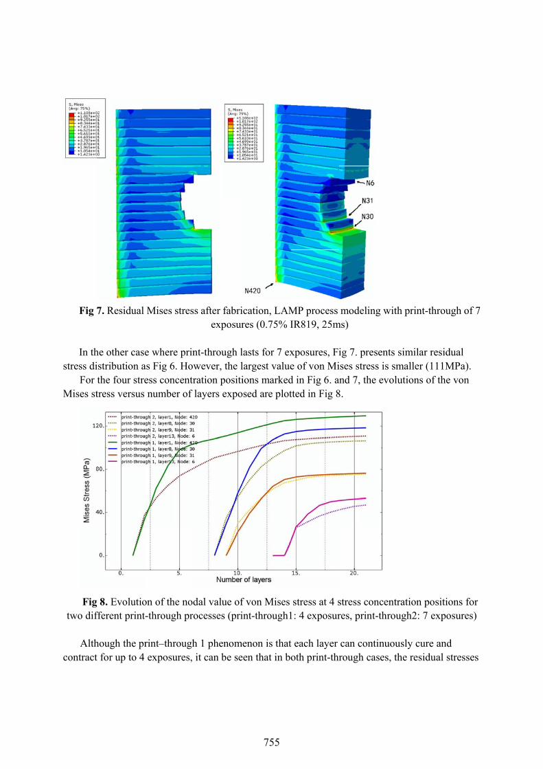
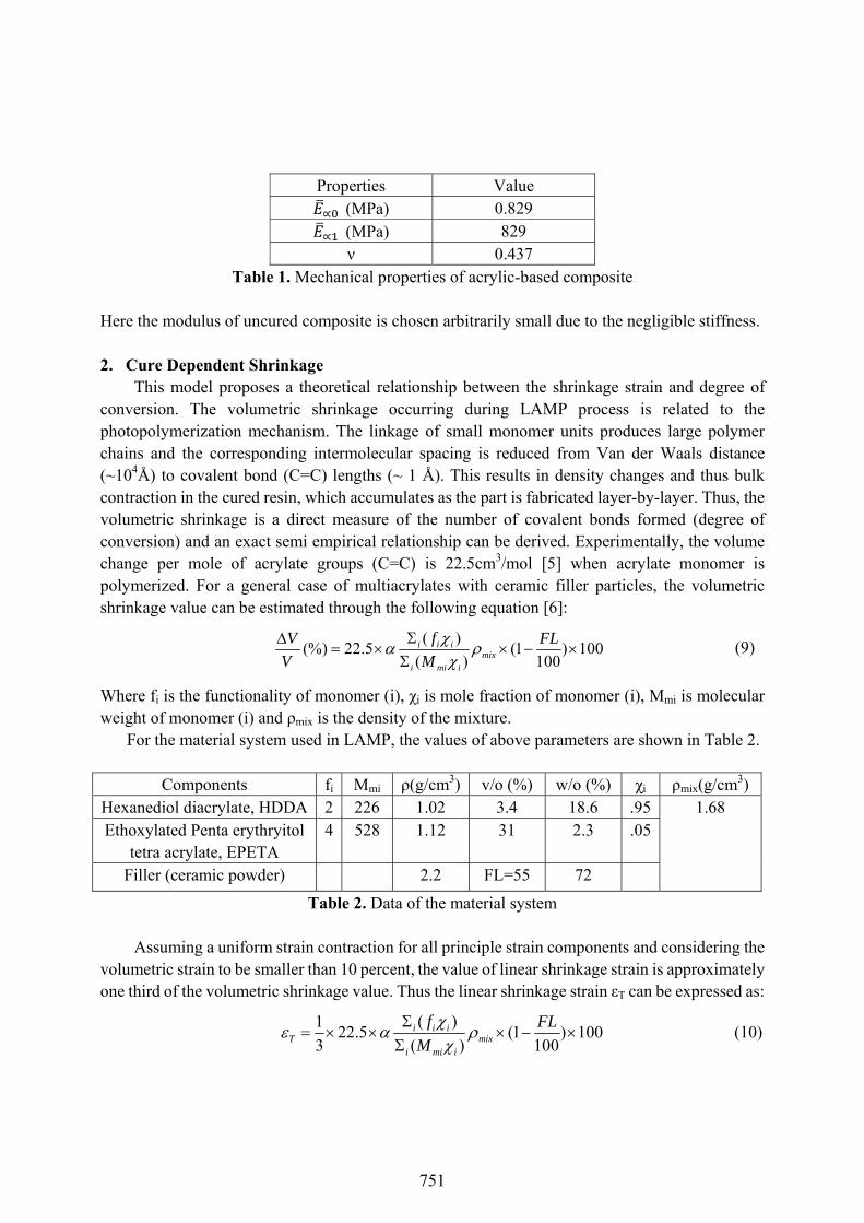
Fig 7
In thstress di
For Mises st
Figtwo dif
Althcontract
7. Residual
he other caseistribution athe four stretress versus
8. Evolutiofferent print-
hough the prt for up to 4
Mises stres
e where prinas Fig 6. Howess concentrnumber of
on of the nod-through pro
rint–throughexposures,
s after fabri
exposur
nt-through lwever, the lration positilayers expo
dal value ofocesses (pri
h 1 phenomit can be se
ication, LAMres (0.75% I
lasts for 7 exlargest valueions marked
osed are plot
f von Mises int-through1
enon is thateen that in bo
MP process IR819, 25m
xposures, Fie of von Mid in Fig 6. antted in Fig 8
stress at 4 s1: 4 exposur
t each layer oth print-thr
modeling w
ms)
ig 7. presenises stress isnd 7, the ev
8.
stress conceres, print-thr
can continurough cases
with print-th
nts similar res smaller (11volutions of
entration posrough2: 7 ex
uously cure s, the residua
hrough of 7
esidual 11MPa). the von
sitions for xposures)
and al stresses
755

increasecumulatprint-thrprint-thrlayers hanon-unifindicativ 2. Effe
LAevolve cshrinkagstronglyconstrain
To son a squmold. Ncarefullyprocess.
The results a
It cvalues oand disto
e for about 7tive internalrough 1 withrough 2 withave larger dformity in thve of its dee
ect of the strAMP is a laycontinuouslyge occurs pay depend on ned boundastudy the couare board o
Now we needy designed t The diamefirst config
are shown in
a. MisesFi
can be seen tof top-right horted positio
7 exposures stress will nh IR184 cauh IR819. Th
difference ofhe conversioeper curing c
ructure conyer-by-layery. Since the arallel to theorientation
aries. nfiguration
of which twod to add twoto minimizeter of each h
guration is ton Fig 9.
s Stress ig 9. 3-D Mo
that both thhole are preons are the b
and then apnot change
uses the intehis is due to f conversionon as a resulcapability an
nfigurationr manufactur
building die layer surfas and direct
effect for Lo side surfaco holes on the the internahole is 0.6mo set these tw
odeling resu
e stress andetty small. Fbottom-righ
pproximate aafter 6 layer
ernal stress tthe fact tha
n degree andlt of UV lighnd lower ab
n ring processirection of pace, the evoltions, such a
LAMP built ces are fixedhis board, thal stress prodmm and the swo holes on
ult of square
d distortion aFor the bottoht corner, wh
a constant vrs are built ato increase fat for print-thd thus can acht penetratio
bsorption co
s in which thpart is verticlution of stras the relativ
part, simulad, just like the configuraduced durinsquare boarn the diagon
b. Dispe board with
around the bom-left holehere close to
value. Thus,above. Fig 8faster than through 1 thccumulate mon in the cas
oefficient.
he internal scal to each laresses shouldve position a
ations were the trailing eation of thesng the layer-rd size is 2mnal of the squ
placement Mh diagonal h
bottom-left h, the most sto the bottom
for each lay8. also showthe case of he two neighmore stress. se of IR 819
stresses of aayer and cond also in somamong hole
still conducedge inside se two holes-by-layer cu
mm×2mm×
uare. The m
Magnitude holes
hole are largtress concen
m bound of t
yer the ws that
hboring The lower
9 is also an
a part nstrained me sense
es and
cted based the airfoil
s should be uring
0.4mm. modeling
ge while ntrated the square
756

and the rand the In obottom-modelin
F
It ithan thobottom halso shobottom hdesired nsimilar a
F
right solid adistorted areorder to seeleft hole and
ng results are
a. MisesFig 10. 3-D
s found thatose in the diahole are not
ows that strehole. So, in not to be aliat different d
a. Misesig 11. 3-D M
area. For theea is the left the effect od move the e shown in F
s Stress D Modeling r
t both the vaagonal alignt changed wess concentr
the verticaligned verticdirections.
s Stress Modeling re
e top hole, thft border of tof the relativtop hole to Fig 10.
result of squ
alues of thened case. Th
while the posration area ol direction, hcally. Also, t
esult of squa
he stress cothe hole. ve position obe just verti
uare board w
largest stres
he stress consitions of topof the top hoholes shouldthe sizes of
are board wi
ncentrated p
of these twoical aligned
b. Dispwith vertica
ss and the dncentrated ap hole move
ole is very cld not be toosolid areas
b. Dispith vertical a
position is t
o holes, we fd to the botto
placement Ml alligned ho
displacemenand distortede from its lelose even ge close to eacaround the h
placement Malligned hol
the bottom-l
fix the positom one. The
Magnitude oles at the le
nt are a littled positions oeft to right. Tet touch witch other andhole should
Magnitude les at the ce
left corner
tion of the e
eft
bigger of the The figure th the d holes are d be kept
nter
757

Figcenter oeven wo
FigAlthougmuch ledisplacedisplace
Fi
g 11. shows f the square
orse.
a. MisesFig 12.
g 12 shows tgh the positiss than the f
ement at critement) are p
ig 13. Comp
the modeline. The stress
s Stress 3-D Modeli
the modelinons of stresfront cases. tical positionplot in Fig 13
parison for t
ng result of ses are smal
ing result of
ng result of ts concentratThe compans (bottom c3. and 14.
the evolution
the case whler than cas
f square boa
the case whetion and dis
arison resultcorner of ho
ns of stress
here verticale 2, but the
b. Dispard with hor
ere two holestortion are nts for the evoole for stres
at bottom c
l aligned hodistortion a
placement Mrizontal allig
es are alignenot changedolutions of ss and larges
corner (layer
les are movat the bottom
Magnitude gned holes
ed horizontad, the valuesstress and st value posi
r3) in four c
ved to the m becomes
ally. s become
ition for
cases
758
F
Obhorizontdiagona(center) distortiothe holeboundardistortiokeep the
ThiLAMP pphenomlayers ancorner oconfigurthe caseAnd thedistortioarea arofar awayunderstadelamintrailing eFuture w
Fig 14. Com
bviously, fortally has mully and vertis the worst
on, horizonta should be a
ries, especiaon increase re holes away
is paper preprocess. Sim
mena. For bond then beco
of hole and pration on str in which ho vertical alig
on, distributiund the holey from the franding the Lnation and diedge in the
work will be
mparison for
r both stressuch smaller ically (left) t. So we canal alignmenas uniform aally the horizrapidly in 7 y from each
esents theoremulations arth 4 layers aomes constapossibly cauress and distoles are aliggnment of hion of holese in a balan
free boundarLAMP proceimensional airfoil mold
e conducted
the evolutio
s and distortvalue than oare the wor
n conclude tnt of holes isas possible. zontal ones,layers and b
h other for at
Summaetical concepre conductedand 7 layersant. The mouses the inititortion are sgned horizonholes shoulds should be aced state in ries to avoidess and for pdiscrepancy
d built by LAto model th
ons of large
tion, the conother cases. rst. For distothat for decrs better wheThe positio, to minimizbecome stabt least 7 laye
ary and Copts and a md to study ths deep curinost serious stiation of crastudied thrountally has thd be avoidedas uniform asome sense
d curl distorproviding sty caused by AMP is onehe stress evo
est displacem
nfiguration wFor stress,
ortion, the creasing the sen the spacinon of hole shze distortionble after aboers verticall
nclusionsmechanical mhe effect of dng, the stresstress concenack and delaugh simulathe smallest vd when spacas possible e. Also, the hrtion. This wtrategies to stress conc
e of the partsolution in th
ment (layer1
where holescases in wh
case with verstress conceng is small ahould be farn. Also, valuout 10 layerly.
model for thedifferent pris continues tntration occamination. Ttion of four value of strecing is smallso as to keehollow struc
work is a funreduce defeentrations as with most
he trailing ed
1) in four ca
are alignedhich holes arrtically alig
entration andand the arear away fromues of stressrs. So it is be
e layer-by-lint-through to increase urs at the bo
The effects ocases. It is fess and distol. To minim
ep the cure octure is bettndamental sects such as and distortio
serious defdge.
ases
d re aligned
gned holes d
as around m the free s and etter to
ayer
for 7 ottom of holes found that ortion.
mize the of solid ter to be tudy for cracks,
on. The fects.
759
References
[1] S. H. Dillman and J. C. Seferis, "Kinetic Viscoelasticity for the Dynamic Mechanical
Properties of Polymer Systems," Journal of Macromolecular Science - Chemistry, 1987. [2] S. H. McGee, "Curing of Farticulate Filled Composites," Polymer Engineering and
Science, 1982. [3] T. A. Bogetti and J. John W. Gillespie, "Process-Induced Stress and Deformation in
Thick-section Thermoset Composite Laminates," Journal of Composite Materials, vol. 26, 1992.
[4] J. Qu and M. Cherkaoui, "Fundamentals of Micromechanics of Solids," 2006. [5] N. Silikas, A. Al-Kheraif, and D. C. Watts, "Influence of P/L Ratio and Peroxide/amine
Concentrations on Shrinkage-strain Kinetics During setting of PMMA/MMA Biomaterial Formulations," Biomaterials, vol. 26(2), pp. 197-204, 2005.
[6] K. Kambly, D. Yuan, P. Shao, and S. Das, "Characterization of Shrinkage and Stress in Large Area Maskless Photopolymerization," Solid Freeform Fabrication Symposium Proceedings, 2009.
760