taranakipine weatherboard systemtaranakipine.co.nz/wp-content/uploads/2015/06/... · ·...
TRANSCRIPT
T A R A N A K I P I N E W E A T H E R B O A R D S Y S T E M 1
TIMBER WEATHERBOARDS – NATURALLY BETTER FOR MORE THAN A CENTURY
T A R A N A K I P I N E
Insta l la t ion in format ion and technica l drawings
WEATHERBOARD SYSTEM
www.taranakipine.co.nz
T A R A N A K I P I N E W E A T H E R B O A R D S Y S T E M 1
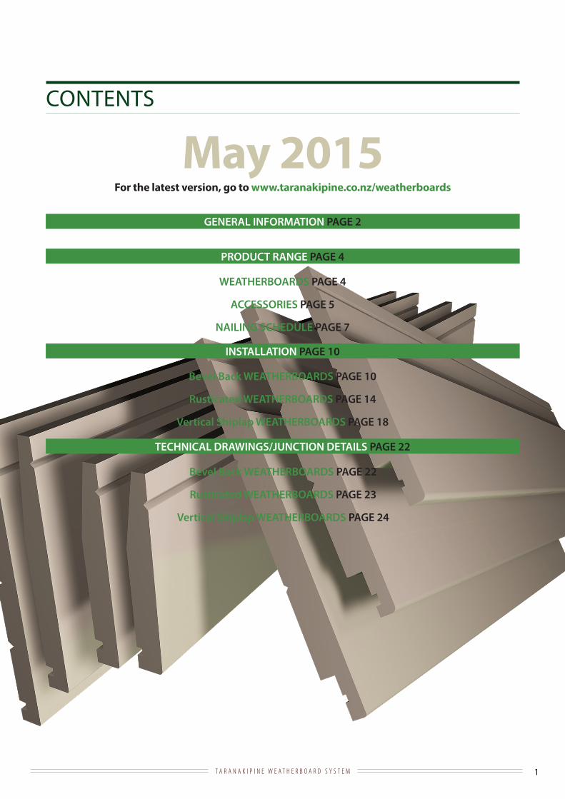
CONTENTS
GENERAL INFORMATION PAGE 2
PRODUCT RANGE PAGE 4
INSTALLATION PAGE 10
TECHNICAL DRAWINGS/JUNCTION DETAILS PAGE 22
WEATHERBOARDS PAGE 4
ACCESSORIES PAGE 5
NAILING SCHEDULE PAGE 7
Bevel Back WEATHERBOARDS PAGE 10
Rusticated WEATHERBOARDS PAGE 14
Vertical Shiplap WEATHERBOARDS PAGE 18
For the latest version, go to www.taranakipine.co.nz/weatherboards
May 2015
Bevel Back WEATHERBOARDS PAGE 22
Rusticated WEATHERBOARDS PAGE 23
Vertical Shiplap WEATHERBOARDS PAGE 24

T A R A N A K I P I N E W E A T H E R B O A R D S Y S T E M 2
GENERALa. Scope
This manual is specific to Taranakipine Weatherboard Systems. Timber weatherboards can be used for buildings that fall within the scope of NZS 3604 Timber Framed Buildings and Acceptable Solutions E2/AS1. Although timber weatherboards can be used on buildings that have a maximum Weathertightness Risk Matrix of 20, you will need to use Acceptable Solutions E2/AS1 Table 3.0 to ascertain which is the correct product and application for your project.
When using introduced components such as flashings, sealants, paint etc please follow the manufacturer’s instructions.Recommendations by Taranakipine are based on good building practice and are not a complete statement of all relevant data. As the installation of the products rely on factors outside the control of Taranakipine, Taranakipine assumes no responsibility for work/systems used in connection with the installation of our products and their suitability to satisfy relevant Building Codes and Regulations, Standards and Council Requirements.
b. Product Information
· Manufactured from environmentally responsible Radiata Pine· Engineered to produce long, defect free products· Kiln dried to between 8%-15% for stability· Treated with organic biocides and fungicides to H3.1 level· Factory coated with an architectural primer (available also with a 2 coat primer and undercoat paint system)
c. Storage & Handling
· Keep all Taranakipine Weatherboards dry and protected from the elements at all times before installation. Inside storage, under cover is best· Schedule the delivery of Taranakipine Weatherboards to site as close to the time of installation as possible· Unload Taranakipine Weatherboards either by hand or a lifting device – do not ‘tip’ them off a truck deck· Carry individual boards on their edge· Do not drag boards in a way that will damage the surface. If the primer has been damaged and bare wood is showing, sand the area to a clean, smooth finish and re prime with a quality primer· Lay flat with bearers underneath at a maximum of 1 metre spacing · Ensure Taranakipine Weatherboards are stored a minimum of 150mm off the ground· If the surface underneath is damp, place a moisture resistant sheet (ie polythene) under the Taranakipine Weatherboards
d. Before Installation
· Check the moisture content and dimensions of Taranakipine Weatherboards. If these are not as per our factory specifications delay installation and contact Taranakipine for advice· Ensure that the framing complies with all requirements of NZS 3604, including the straightness of the framing and the moisture content being less than 20% · Ensure the underlays meet all the requirements of E2/AS1 Table 23 and Section 9.1.7
e. Flashings
· Ensure that these comply with the durability requirements as shown in NZS 3604 section 4 and E2/AS1 Table 20· The design and fabrication needs to comply with E2/AS1 Section 9· Window and door manufacturers are responsible for the supply of head flashings· If the flashing is to be in alongside any copper based timber treatment, a layer of building wrap needs to be inserted between them as a barrier

T A R A N A K I P I N E W E A T H E R B O A R D S Y S T E M 3
f. Sealants and Air Seals
· Sealants are only part of the system to keep buildings weathertight and should not be relied on as being the primary method of protection· All sealants need to be suitable for exterior use· Air Seals are required where a hole, penetration or void (ie windows, metre boxes, doors) occur · Air Seals have two components being Backing Rod of a diameter to suit the gap and the Sealant (acrylic latex, silicon sealant or self expanding polyurethane foam) · Any excess sealant needs to be trimmed
g. Direct Fix / Drained and Vented Cavities
· In low risk situations, Taranakipine Weatherboards can be fixed directly to the studs. Check Acceptable Solutions E2/AS1 Table 3.0· For Bevel Back weatherboards when the risk score exceeds 12, cavity battens are required· For Rusticated weatherboards when the risk score exceeds 6, cavity battens are required· For Vertical Shiplap weatherboards when the risk score exceeds 6, cavity battens are required and it is an Alternative Solution. The cavity battens are horizontal and are castellated timber battens or Cavibat extruded plastic battens· Taranakipine produces cavity battens (44x21mm treated to H3.1) for Bevel Back and Rusticated weatherboards· Cavity closures must be fitted to the bottom of the cavity to prevent vermin entry
h. Painting and preparation
· Always check that Taranakipine Weatherboards are dry (no greater than 15% moisture content) and clean before applying any finishing coats of paint· Preparation and painting must be carried out in a tradesman like manner and to the current requirements of AS/NZS 2311 Guide to Painting of Buildings· If possible it is advisable to apply one coat of the finishing paint before installation. This will give the weatherboards an extra level of protection during the construction process as well as giving good cover at the laps that may move as the total building settles over time· Fill all nail holes with an exterior grade filler as per the manufacturer’s instructions - this should be done as soon as practical to reduce the chance of moisture intrusion. Then sand to a smooth finish and spot prime· Seal all end cuts, mitres, notchings, borings or similar with a suitable good quality primer during the construction process· If the primed surface has been exposed to elements for some time, the surface may have become chalky. If this happens, sanding will be required. Ensure any exposed timber is resealed using a good quality primer before application of the top coats· Select a paint colour with a LRV (Light Reflectance Value) of 45 or more (where 0 = Black and 100 = white measured to ASTM C1549 or ASTM E903) and a gloss level of 10% or more· Using darker than recommended colours will generate more heat in the board and can promote resin bleed· Apply two top coats of a high quality exterior paint as per the manufacturers recommendations · For a better quality, long term paint system a good quality undercoat can be applied before the topcoats
i. Maintenance
· All products are affected by their surrounding environment. By maintaining your property to the level appropriate to its surrounding environment you will ensure its long term performance and beauty· Paint generally requires up to 4 weeks to completely cure, so keep cleaning to a minimum until after this period to avoid any potential damage · Maintenance is generally recommended to be carried out every 12 months, but in more corrosive environments (ie, coastal areas or industrial or geothermal atmospheres) every 6 months is recommended. Pay special attention to areas that do not get regular rain washing such as under soffits · Wash down to remove salt deposits, dirt build up, mould and insect traces (do not use a water blaster)· Moss, mould and lichen can cause long term damage to paint so special care needs to be taken in removing it. Consult your paint supplier for the appropriate cleaner · Check sealants and replace them if they are showing signs of loss of edge adhesion or surface cracking· Check flashings and replace any that have been damaged to the point of allowing water intrusion· Check for missing attachments and loose fittings· In areas of high Weathertightness risk take particular care and resolve any issues immediately to avoid a larger long term problem · Maintain, and where required reapply paint finishes in accordance with the paint manufacturers recommendations
T A R A N A K I P I N E W E A T H E R B O A R D S Y S T E M 4
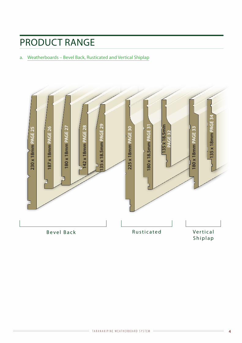
PRODUCT RANGEa. Weatherboards – Bevel Back, Rusticated and Vertical Shiplap
187
x 18
mm
PA
GE
26
142
x 18
mm
PA
GE
28
230
x 18
mm
PAG
E 25
135
x 18
.5m
m P
AG
E 29
225
x 18
mm
PA
GE
30
180
x 18
.5m
m P
AG
E 31
135
x 18
.5m
m
PAG
E 32
B e v e l B a c k R u s t i c a t e d
180
x 18
mm
PA
GE
27
180
x 18
mm
PA
GE
33
135
x 18
mm
PA
GE
34
Ve r t i c a l S h i p l a p

T A R A N A K I P I N E W E A T H E R B O A R D S Y S T E M 5
PRODUCT RANGEb. Accessories
QUAD 18x18LENGTH 5.4m
SCRIBER 40x10LENGTH 5.4m
EAVES MOULD 18x18LENGTH 5.4m
EAVES MOULD 25x18LENGTH 5.4m
PENCIL ROUND 42x42 LENGTH 5.4m
SCRIBER 40x18LENGTH 5.4m
• All products are H3.1 treated• All accessories are primed with the exception of 44x21 cavity batten
TG&V EAVES LINER 138x19LENGTH 4.88m
PAGE 39 PAGE 40
PAGE 36
PAGE 38
PAGE 37
PAGE 41
FASCIA 225x29LENGTH 6m
PAGE 42 PAGE 43
FASCIA 180x29LENGTH 6m
FASCIA 135x29LENGTH 6m
PAGE 44
FASCIA 225x18LENGTH 6m
PAGE 45
PAGE 48
PAGE 46
FASCIA 180x18LENGTH 6m
FASCIA 135x18LENGTH 6m
PAGE 47
FASCIA 280x29LENGTH 6m
PAGE 35

T A R A N A K I P I N E W E A T H E R B O A R D S Y S T E M 6
PRODUCT RANGE
FASCIA 280x18LENGTH 6m
CAVITY BATTEN 44x21LENGTH 5.4m
• All products are H3.1 treated• All accessories are primed with the exception of 44x21 cavity batten
b. Accessories (cont)
GROOVED FACING 185x18LENGTH 5.4m
GROOVED FACING 138x18LENGTH 5.4m
GROOVED FACING 90x18LENGTH 5.4m
GROOVED FACING 65x18LENGTH 5.4m
SCRIBER 60x18LENGTH 5.4m
SILL BLOCK 65x37LENGTH 5.4m
INTERNAL BOXED CORNER (2 PIECE SET) LENGTH 5.4m
RUSTIC WEATHERBOARD PLUGPER BAG (100pcs x 40mm long)
EXTERNAL BOXED CORNER (2 PIECE SET) LENGTH 5.4m
EAVES MOULD 40x27LENGTH 5.4m
PAGE 54PAGE 53
PAGE 56 PAGE 57
PAGE 60
PAGE 52
PAGE 55
PAGE 58 PAGE 59
PAGE 49 PAGE 50 PAGE 51

T A R A N A K I P I N E W E A T H E R B O A R D S Y S T E M 7
Profile Application Size mm Nail size Nail PositionTaranakipine Bevel Back
Direct Fix 135x18.5, 142x18, 180x18.5, 187x18, 230x18 75x3.15 Single nail on every stud 42mm from bottom of board
Taranakipine Bevel Back
Cavity Fix 135x18.5, 142x18, 180x18.5, 187x18, 230x18 90x4.01 or 75x3.152 Single nail on every stud 42mm from bottom of board
Taranakipine Rusticated
Direct Fix 135x18.5, 180x18.5, 225x18 60x2.8 Single nail on every stud 37mm from bottom of board
Taranakipine Rusticated
Cavity Fix 135x18.5, 180x18.5, 225x18 75x3.153 or 60x2.84 Single nail on every stud 37mm from bottom of board
Taranakipine Vertical Shiplap
Direct Fix 135x18, 180x18 60x2.8 Single nail on every nog 35mm from side of the lap
Taranakipine Vertical Shiplap
Cavity Fix 135x18, 180x18 75x3.15 Single nail on every nog 35mm from side of the lap5,6
Cavity Battens Only horizontal weatherboards
44x21 40x2.51,3 or 60x2.82,4 or 64x2.82,4
300mm centres maximum
1. For Bevel Back profiles as per Acceptable Solutions E2/AS1 ‘temporary fixing of cavity battens’ you can use 40x2.5 galvanised flat head nails to attach the cavity battens. When you do this the weatherboard needs to be attached using 90x4.0 nails. See diagram 1 below.
2. As an alternative you can structurally attach the cavity battens to the studs using 60x2.8 hand driven or 64x2.8 power driven nails as per diagram 2. When you do this the weatherboards can be attached using 75x3.15 nails. NOTE: This is an Alternative Solution and needs to be detailed and presented to the Building Consent Authority
1 2
300mm maximum
12mm either side of centreline
hand-driven 60x2.8 or power-driven 64x2.8
cavity batten
wall underlay
40x2.5
90x4.0
hand-driven 60x2.8 or power-driven 64x2.8
75x3.15
cavity batten
Taranakipine Bevel Back weatherboard
cavity battenwall framing
wall framing
wall underlay
wall underlay
32mm galvanised brad nail for temporary fixing
32mm galvanised brad nail for temporary fixing
c. Nailing Schedule
· Taranakipine recommends hand nailing· Hot dip galvanising must meet the requirements of AS/NZS 4680:2006· In sea spray zones all fittings must be type 316 stainless steel· Use jolt head or annular grooved nails· Nails must penetrate each stud by a minimum of 35mm· E2/AS1 Acceptable Solutions states that weatherboards are required to be fastened over a cavity when the risk score exceeds 6 for Rusticated profiles and exceeds 12 for Bevel Back profiles · E2/AS1 Acceptable Solutions states that Vertical Shiplap weatherboards can be direct fix and on risk scores of 6 or less. For use in higher risk score applications, Vertical Shiplap can be used as an Alternative Solution with horizontal cavity battens up to a risk score of 20. Horizontal cavity battens can be castellated timber batten or Cavibat plastic extruded battens · Vertical Shiplap requires fixing the nogs at 480mm centres maximum
T A R A N A K I P I N E W E A T H E R B O A R D S Y S T E M 8
3 4
300mm maximum
12mm either side of centreline
hand-driven 60x2.8 or power-driven 64x2.8
cavity batten
wall underlay
40x2.5
75x3.15
hand-driven 60x2.8 or power-driven 64x2.8
60x2.8
cavity batten
Taranakipine Rusticated weatherboard
cavity battenwall framing
wall framing
wall underlay
wall underlay
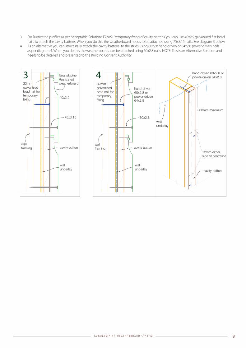
3. For Rusticated profiles as per Acceptable Solutions E2/AS1 ‘temporary fixing of cavity battens’ you can use 40x2.5 galvanised flat head nails to attach the cavity battens. When you do this the weatherboard needs to be attached using 75x3.15 nails. See diagram 3 below
4. As an alternative you can structurally attach the cavity battens to the studs using 60x2.8 hand driven or 64x2.8 power driven nails as per diagram 4. When you do this the weatherboards can be attached using 60x2.8 nails. NOTE: This is an Alternative Solution and needs to be detailed and presented to the Building Consent Authority
32mm galvanised brad nail for temporary fixing
32mm galvanised brad nail for temporary fixing
T A R A N A K I P I N E W E A T H E R B O A R D S Y S T E M 9
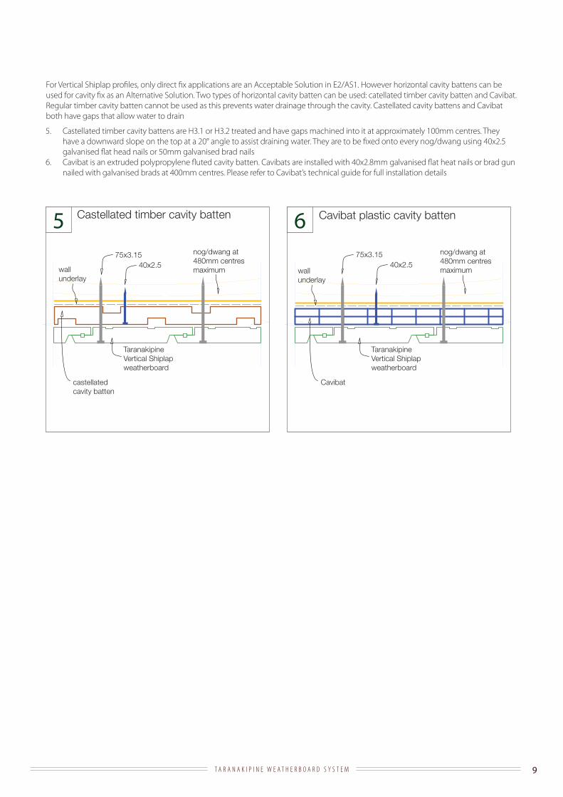
5. Castellated timber cavity battens are H3.1 or H3.2 treated and have gaps machined into it at approximately 100mm centres. They have a downward slope on the top at a 20° angle to assist draining water. They are to be fixed onto every nog/dwang using 40x2.5 galvanised flat head nails or 50mm galvanised brad nails
6. Cavibat is an extruded polypropylene fluted cavity batten. Cavibats are installed with 40x2.8mm galvanised flat heat nails or brad gun nailed with galvanised brads at 400mm centres. Please refer to Cavibat’s technical guide for full installation details
5 6nog/dwang at 480mm centres maximum
nog/dwang at 480mm centres maximum
75x3.1540x2.5
75x3.1540x2.5
wall underlay
wall underlay
Taranakipine Vertical Shiplap weatherboard
Taranakipine Vertical Shiplap weatherboard
castellated cavity batten
Cavibat
Castellated timber cavity batten Cavibat plastic cavity batten
For Vertical Shiplap profiles, only direct fix applications are an Acceptable Solution in E2/AS1. However horizontal cavity battens can be used for cavity fix as an Alternative Solution. Two types of horizontal cavity batten can be used: catellated timber cavity batten and Cavibat. Regular timber cavity batten cannot be used as this prevents water drainage through the cavity. Castellated cavity battens and Cavibat both have gaps that allow water to drain

T A R A N A K I P I N E W E A T H E R B O A R D S Y S T E M 10
INSTALLATIONa. Bevel Back
· Set Out Guide - the required overlap is 32mm
· Fixing Method
1. Taranakipine recommend hand nailing (see nailing schedule). Installing Taranakipine Weatherboards is a ‘finishing’ operation, not a framing one
2. Nails must have a minimum penetration of 35mm in to the wall framing 3. If nail gun application is used, make sure the gun does not damage the surface of the board, the pressure is correctly set to
drive the nail below the timber surface but gives adequate holding, and that the galvanising is of the necessary standard4. The bottom weatherboard should overlap the bottom plate or bearer by a minimum of 50mm5. Make sure the bottom of the weatherboard is no closer than 150mm from a paved/concrete ground surface or 225mm
from an uncovered ground surface6. Use only one nail per board at each fixing point7. Locate nails approximately 42mm above the bottom edge of the board. Take care to not nail through the board underneath8. Punch the nail to below the surface and fill with an exterior grade filler as soon as is practical9. Start fixing weatherboards near the centre of the board and work your way outwards10. The weatherboards can be brad nailed at the top above the water groove to temporarily fix the weatherboard in place
before face nailing. The brad nails must be galvanised or stainless steel, 32mm long or less, and 2mm width or less. The brad nail is to be fixed on the minimum number of studs necessary to hold the weatherboard in the proper position and no more than one brad nail per stud
11. Pre drill weatherboards (to avoid splitting) for nail locations within 50mm of board ends12. The top board may have to be cut to neatly fit under the soffit
· Cuts / Joins
1. Minimise joins by planning your cutting to use full lengths where possible 2. Where joins are necessary they must be done over studs or battens. Cut the joint at a 45° angle and face this away from the
prevailing weather3. Stagger the joins so that no two joins are directly overlapping. Avoid placing the join over water drip lines, for example
under the side edge of a window 4. Prime the cut ends and allow the paint to dry 5. For extra protection an exterior grade silicon can be used in between the joining pieces6. Use one nail through the overlapping board to join7. A flat soaker can be used over this join
32mm galvanised brad nail for temporary fixing
single nail as per schedule on page 7
32 min overlap
radius edge
10
Taranakipine Bevel Back weatherboard
32 mm min overlap
wall underlay
single nail as per schedule on page 7
32mm galvanised brad nail for temporary fixing

T A R A N A K I P I N E W E A T H E R B O A R D S Y S T E M 11
· Corners – External
1. Either Taranakipine Box Corners with scribers, or soakers can be used (see below diagrams)2. Box corners must cover the weatherboards by a minimum of 50mm3. Assemble the box corners with 50x2.5mm galvanised or stainless steel jolt head nails at approximately 250mm centres –
pre drill holes where needed4. Position the Taranakipine Box Corners and nail over Taranakipine Weatherboards using 75x3.15mm galvanised or stainless
steel jolt head nails at approximately 450mm centres, taking care to not nail through two layers of weatherboard5. Fit a tightly cut scriber over the weatherboard against the box corner and nail at 450mm centres using 60x2.8mm (for
40/60x18 scribers) or 50x2.5mm (for 40x10 scribers) galvanised or stainless steel jolt head nails. Pre drilling the nail holes is required through the scribers
6. Ensure that all cut ends are primed and all nail holes are filled with an exterior grade filler
wall underlay corner soaker
Taranakipine Bevel Back Weatherboard
wall underlay carried around corner
Taranakipine Bevel Back Weatherboard
scriber
Taranakipine Box Corner
concrete foundation wall to give 150mm minimum clearance to paving (225mm to ground) at bottom of cladding
T A R A N A K I P I N E W E A T H E R B O A R D S Y S T E M 12
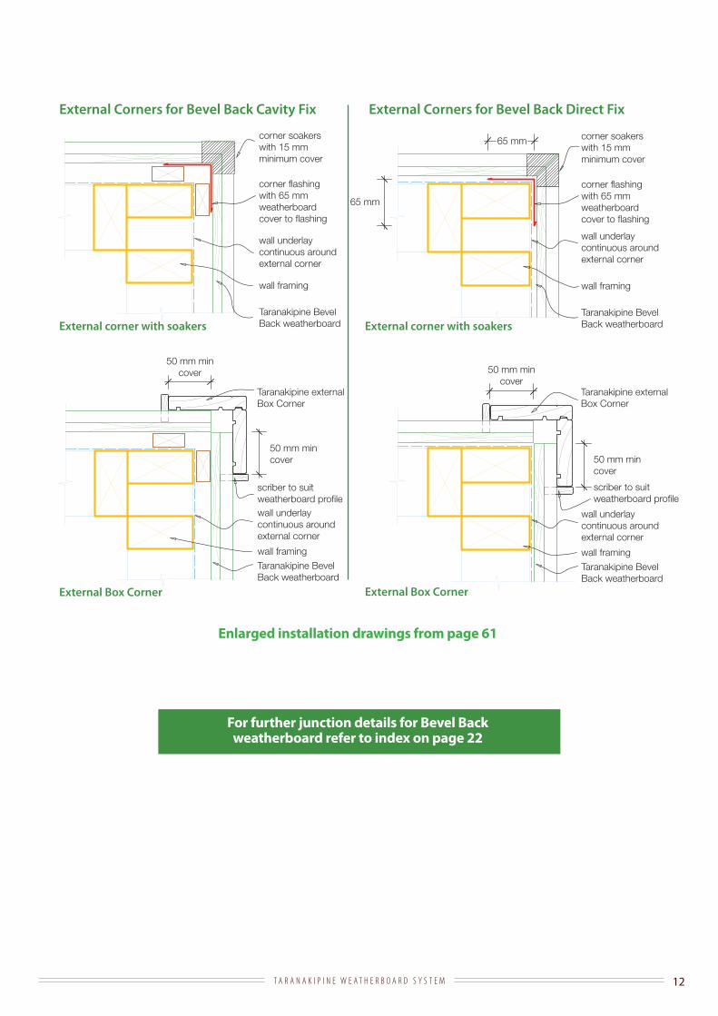
For further junction details for Bevel Back weatherboard refer to index on page 22
Enlarged installation drawings from page 61
External Corners for Bevel Back Cavity Fix External Corners for Bevel Back Direct Fix
External corner with soakers
External Box Corner External Box Corner
External corner with soakers
65 mm
65 mm corner soakers with 15 mm minimum cover
corner flashing with 65 mm weatherboard cover to flashing
wall underlay continuous around external corner
Taranakipine Bevel Back weatherboard
wall framing
corner soakers with 15 mm minimum cover
corner flashing with 65 mm weatherboard cover to flashing
wall underlay continuous around external corner
Taranakipine Bevel Back weatherboard
wall framing
Taranakipine Bevel Back weatherboard
wall framing
wall underlay continuous around external corner
Taranakipine externalBox Corner
50 mm min cover
scriber to suit weatherboard profile
Taranakipine Bevel Back weatherboard
wall framing
wall underlay continuous around external corner
Taranakipine externalBox Corner
50 mm min cover
scriber to suit weatherboard profile
50 mm min cover 50 mm min
cover

T A R A N A K I P I N E W E A T H E R B O A R D S Y S T E M 13
· Corners – Internal
1. Taranakipine Box Corners with scriber can be used or the weatherboards can be butt joined (see below diagrams) 2. Box corners must cover the weatherboards by a minimum of 50mm3. Assemble the Box Corners with 50x2.5mm galvanised or stainless steel jolt head nails at approximately 250mm centres –
pre drill holes where needed4. Position the Taranakipine Box Corners and nail over Taranakipine Weatherboards using 75x3.15mm galvanised or stainless
steel jolt head nails at approximately 450mm centres, taking care to not nail through two layers of weatherboard5. Fit a tightly cut scriber over the weatherboard against the Box Corner and nail at 450mm centres using 60x2.8mm (for
40/60x18 scribers) or 50x2.5mm (for 40x10 scribers) galvanised or stainless steel jolt head nails. Pre drilling the nail holes is required through the scribers
6. Ensure that all cut ends are primed and all nail holes are filled with an exterior grade filler
Internal Corners for Bevel Back Cavity Fix Internal Corners for Bevel Back Direct Fix
For further junction details for Bevel Back weatherboard refer to index on page 22
Enlarged installation drawings from page 63
Internal Box Corner with scriber Internal Box Corner with scriber
Butted internal corner Butted internal corner
Taranakipine Bevel Back weatherboard
Taranakipine internal Box Corner
scriber
wall underlay
65 mm overlay offlashing to cladding
Taranakipine Bevel Back weatherboard
Taranakipine internal Box Corner
scriber
wall underlay
65 mm overlay offlashing to cladding
wall underlaywall underlay
butt weatherboards into 42x42 H3.1
butt weatherboards into 42x42 H3.1
one piece corner flashing with 65mm weatherboard cover
one piece corner flashing with 65mm weatherboard cover

T A R A N A K I P I N E W E A T H E R B O A R D S Y S T E M 14
b. Rusticated
· Set Out Guide - the required overlap is 27mm (25mm lap of the board below and a 2mm expansion gap)
· Fixing Method
1. Taranakipine recommend hand nailing (see nailing schedule). Installing Taranakipine Weatherboards is a ‘finishing’ operation, not a framing one
2. Nails must have a minimum penetration of 35mm in to the wall framing 3. If nail gun application is used, make sure the gun does not damage the surface of the board, the pressure is correctly set to
drive the nail below the timber surface but gives adequate holding, and that the galvanising is of the necessary standard4. The bottom weatherboard should overlap the bottom plate or bearer by a minimum of 50mm5. Make sure the bottom of the weatherboard is no closer than 150mm from a paved/concrete ground surface or 225mm
from an uncovered ground surface6. Use only one nail per board at each fixing point7. Locate nails a minimum 37mm above the bottom edge of the board. Take care to not nail through the board underneath8. Punch the nail to below the surface and fill with an exterior grade filler as soon as is practical9. Start fixing weatherboards near the centre of the board and work your way outwards10. The weatherboards can be brad nailed at the top above the water groove to temporarily fix the weatherboard in place
before face nailing. The brad nails must be galvanised or stainless steel, 32mm long or less, and 2mm width or less. The brad nail is to be fixed on the minimum number of studs necessary to hold the weatherboard in the proper position and no more than one brad nail per stud
11. Pre drill weatherboards (to avoid splitting) for nail locations within 50mm of board ends12. The top board may have to be cut to neatly fit under the soffit
· Cuts / Joins
1. Minimise joins by planning your cutting to use full lengths where possible 2. Where joins are necessary they must be done over studs or battens. Cut the joint at a 45° angle and face this away from the
prevailing weather3. Stagger the joins so that no two joins are directly overlapping. Avoid placing the join over water drip lines, for example
under the side edge of a window 4. Prime the cut ends and allow the paint to dry 5. For extra protection an exterior grade silicon can be used in between the joining pieces6. Use one nail through the overlapping board to join
Taranakipine Rusticated weatherboard
wall underlay
Single nail.see nailing schedule on page 7
radius edge
nail 37mm above the lap 25mm lap
2mm expansion gapSingle nail.see nailing schedule on page 7
10mm
32mm galvanised brad nail for temporary fixing
32mm galvanised brad nail for temporary fixing

T A R A N A K I P I N E W E A T H E R B O A R D S Y S T E M 15
· Corners – External
1. Taranakipine Box Corners with scribers or Rustic Plugs are recommended (see below diagrams)2. Box corners must cover the weatherboards by a minimum of 50mm3. Assemble the box corners with 50x2.5mm galvanised or stainless steel jolt head nails at approximately 250mm centres –
pre drill holes where needed4. Position the Taranakipine Box Corners and nail over Taranakipine Weatherboards using 75x3.15mm galvanised or stainless
steel jolt head nails at approximately 450mm centres, taking care to not nail through two layers of weatherboard5. Fit a tightly cut scriber over the weatherboard against the Box Corner and nail at 450mm centres using 60x2.8mm (for
40/60x18 scribers) or 50x2.5mm (for 40x10 scribers) galvanised or stainless steel jolt head nails. Pre drilling the nail holes is required through the scribers. Alternatively, use Taranakipine Rustic Plugs to slide in to the coved cavity at the top of each weatherboard.
6. Ensure that all cut ends are primed and all nail holes are filled with an exterior grade filler
wall underlay carried around corner
Taranakipine Rusticated Weatherboard
Taranakipine Box Corner
concrete foundation wall to give 150mm minimum clearance to paving (225mm to ground) at bottom of cladding
Taranakipine Rustic Plug
Taranakipine scriber
T A R A N A K I P I N E W E A T H E R B O A R D S Y S T E M 16
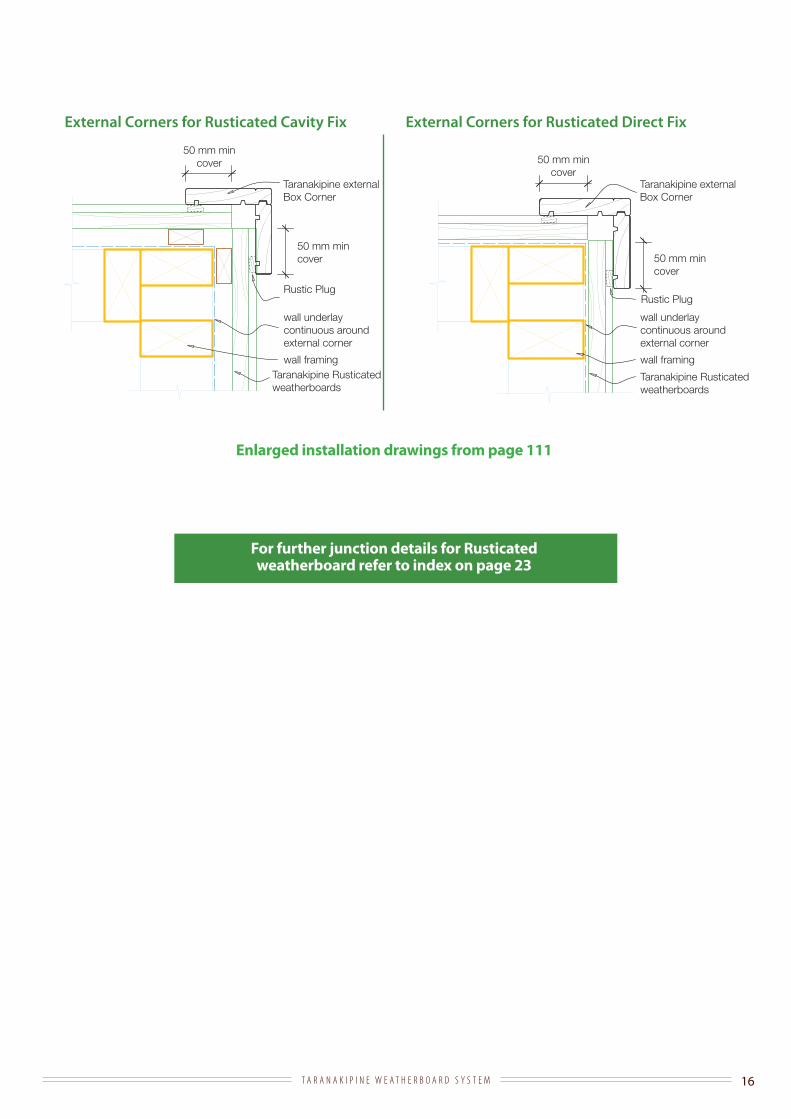
For further junction details for Rusticated weatherboard refer to index on page 23
Enlarged installation drawings from page 111
Taranakipine Rusticated weatherboards
wall framing
wall underlay continuous around external corner
Taranakipine externalBox Corner
50 mm min cover
Rustic Plug
Taranakipine Rusticated weatherboards
wall framing
wall underlay continuous around external corner
Taranakipine externalBox Corner
50 mm min cover
Rustic Plug
50 mm min cover 50 mm min
cover
External Corners for Rusticated Cavity Fix External Corners for Rusticated Direct Fix

T A R A N A K I P I N E W E A T H E R B O A R D S Y S T E M 17
· Corners – Internal
1. Taranakipine Box Corners with scribers or Rustic Plugs can be used (see below diagrams)2. Alternatively the Rusticated weatherboard can be butted against 42x42 H3.1 treated timber (see below diagrams)3. Box corners must cover the weatherboards by a minimum of 50mm4. Assemble the Box Corners with 50x2.5mm galvanised or stainless steel jolt head nails at approximately 250mm centres –
pre drill holes where needed5. Position the Taranakipine Box Corners and nail over Taranakipine Weatherboards using 75x3.15mm galvanised or stainless
steel jolt head nails at approximately 450mm centres, taking care to not nail through two layers of weatherboard6. Fit a tightly cut scriber over the weatherboard against the Box Corner and nail at 450mm centres using 60x2.8mm
(for 40/60x18 scribers) or 50x2.5mm (for 40x10 scribers) galvanised or stainless steel jolt head nails. Alternatively use Taranakipine Rustic Plugs to slide in to the coved cavity at the top of each weatherboard. Pre drilling the nail holes is required through the scribers
7. Ensure that all cut ends are primed and all nail holes are filled with an exterior grade filler
Internal Corners for Rusticated Cavity Fix Internal Corners for Rusticated Direct Fix
For further junction details for Rusticated weatherboard refer to index on page 23
Enlarged installation drawings from page 113
Internal Box Corner with Rustic Plug Internal Box Corner with Rustic Plug
Butted internal corner Butted internal corner
Taranakipine Rusticated weatherboards
Taranakipine internal Box Corner
Taranakipine Rustic Plug
wall underlay
65 mm overlay offlashing to cladding
Taranakipine Rusticated weatherboards
Taranakipine internal Box Corner
Taranakipine Rustic Plug
wall underlay
65 mm overlay offlashing to cladding
wall underlaywall underlay
butt weatherboards into 42x42 H3.1
butt weatherboards into 42x42 H3.1
one piece corner flashing with 65mm weatherboard cover
one piece corner flashing with 65mm weatherboard cover
T A R A N A K I P I N E W E A T H E R B O A R D S Y S T E M 18
see nailing schedule on page 7
Nog/Dwang
Taranakipine Vertical Shiplap weatherboard
35 mm
23 mm overlap
2 mm gap
wall underlay
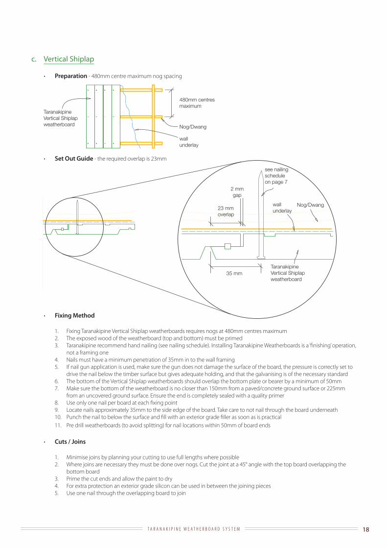
c. Vertical Shiplap
· Preparation - 480mm centre maximum nog spacing
· Set Out Guide - the required overlap is 23mm
· Fixing Method
1. Fixing Taranakipine Vertical Shiplap weatherboards requires nogs at 480mm centres maximum2. The exposed wood of the weatherboard (top and bottom) must be primed3. Taranakipine recommend hand nailing (see nailing schedule). Installing Taranakipine Weatherboards is a ‘finishing’ operation,
not a framing one4. Nails must have a minimum penetration of 35mm in to the wall framing 5. If nail gun application is used, make sure the gun does not damage the surface of the board, the pressure is correctly set to
drive the nail below the timber surface but gives adequate holding, and that the galvanising is of the necessary standard6. The bottom of the Vertical Shiplap weatherboards should overlap the bottom plate or bearer by a minimum of 50mm7. Make sure the bottom of the weatherboard is no closer than 150mm from a paved/concrete ground surface or 225mm
from an uncovered ground surface. Ensure the end is completely sealed with a quality primer8. Use only one nail per board at each fixing point9. Locate nails approximately 35mm to the side edge of the board. Take care to not nail through the board underneath10. Punch the nail to below the surface and fill with an exterior grade filler as soon as is practical11. Pre drill weatherboards (to avoid splitting) for nail locations within 50mm of board ends
· Cuts / Joins
1. Minimise joins by planning your cutting to use full lengths where possible 2. Where joins are necessary they must be done over nogs. Cut the joint at a 45° angle with the top board overlapping the
bottom board3. Prime the cut ends and allow the paint to dry 4. For extra protection an exterior grade silicon can be used in between the joining pieces5. Use one nail through the overlapping board to join
480mm centres maximum
Nog/Dwang
Taranakipine Vertical Shiplap weatherboard
wall underlay

T A R A N A K I P I N E W E A T H E R B O A R D S Y S T E M 19
· Corners – External
1. Taranakipine Box Corners are recommended (see below diagram)2. Box corners must cover the weatherboards by a minimum of 50mm3. Assemble the Box Corners with 50x2.5mm galvanised or stainless steel jolt head nails at approximately 250mm centres –
pre drill holes where needed4. Position the Box Corners and nail over Taranakipine Vertical Shiplap weatherboards using 75x3.15mm galvanised or stainless
steel jolt head nails at approximately 450mm centres, taking care to not nail through two layers of weatherboard5. Ensure that all cut ends are primed and all nail holes are filled with an exterior grade filler
wall underlay carried around corner
Taranakipine Vertical Shiplap Weatherboard
Taranakipine Box Corner
concrete foundation wall to give 150mm minimum clearance to paving (225mm to ground) at bottom of cladding
T A R A N A K I P I N E W E A T H E R B O A R D S Y S T E M 20
Taranakipine Vertical Shiplap weatherboards
wall framing
wall underlay continuous around external corner
Taranakipine externalBox Corner
50 mm min cover
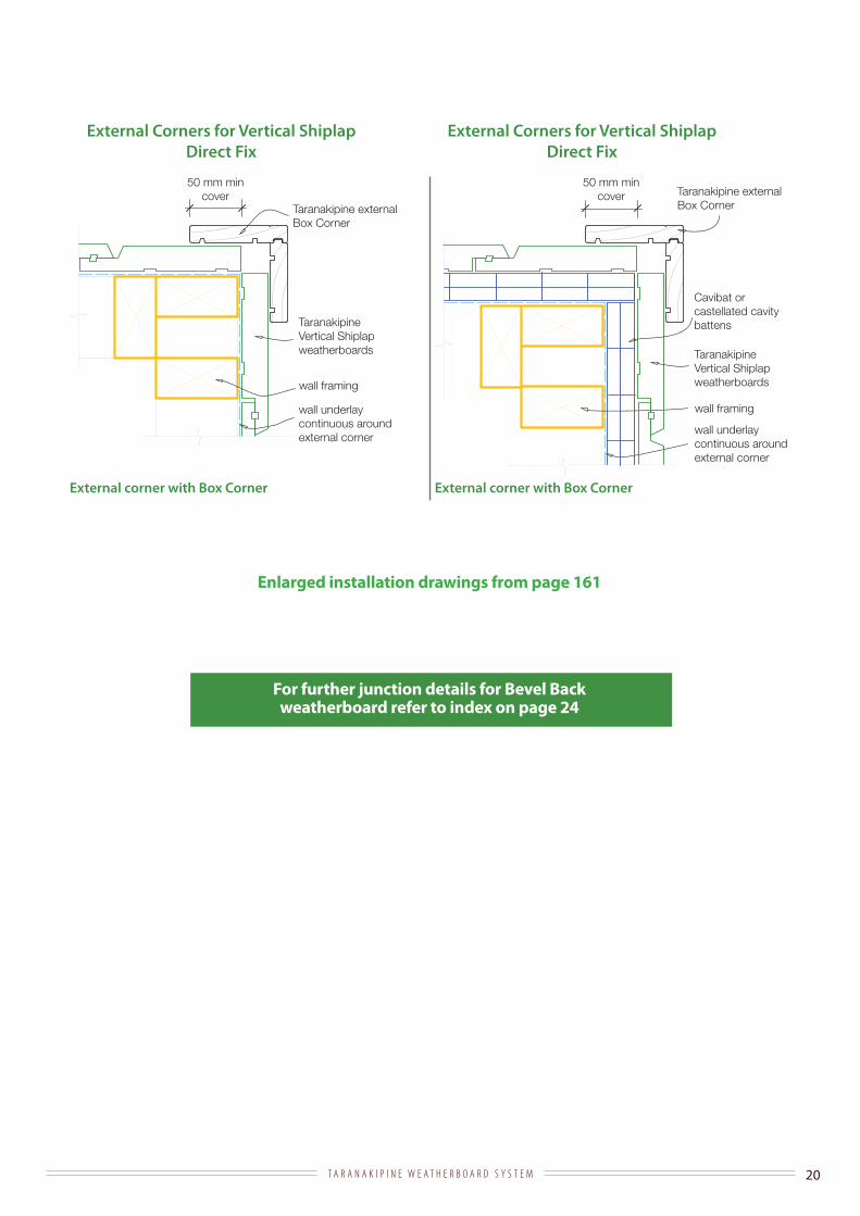
External Corners for Vertical Shiplap Direct Fix
External corner with Box Corner
For further junction details for Bevel Back weatherboard refer to index on page 24
Enlarged installation drawings from page 161
External corner with Box Corner
Taranakipine Vertical Shiplap weatherboards
wall framing
wall underlay continuous around external corner
Taranakipine externalBox Corner
50 mm min cover
External Corners for Vertical Shiplap Direct Fix
Cavibat or castellated cavity battens
T A R A N A K I P I N E W E A T H E R B O A R D S Y S T E M 21
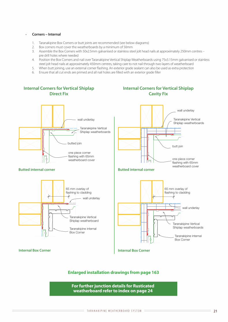
· Corners – Internal
1. Taranakipine Box Corners or butt joints are recommended (see below diagrams) 2. Box corners must cover the weatherboards by a minimum of 50mm3. Assemble the Box Corners with 50x2.5mm galvanised or stainless steel jolt head nails at approximately 250mm centres –
pre drill holes where needed4. Position the Box Corners and nail over Taranakipine Vertical Shiplap Weatherboards using 75x3.15mm galvanised or stainless
steel jolt head nails at approximately 450mm centres, taking care to not nail through two layers of weatherboard5. When butt joining, use an external corner flashing. An exterior grade sealant can also be used as extra protection6. Ensure that all cut ends are primed and all nail holes are filled with an exterior grade filler
Internal Corners for Vertical Shiplap Cavity Fix
Internal Corners for Vertical Shiplap Direct Fix
Internal Box Corner Internal Box Corner
Butted internal cornerButted internal corner
Taranakipine Vertical Shiplap weatherboards
Taranakipine internal Box Corner
wall underlay
65 mm overlay offlashing to cladding
Taranakipine Vertical Shiplap weatherboard
Taranakipine internal Box Corner
wall underlay
65 mm overlay offlashing to cladding
wall underlay
wall underlay
butt joinbutted join
one piece corner flashing with 65mm weatherboard cover
one piece corner flashing with 65mm weatherboard cover
Taranakipine Vertical Shiplap weatherboards
Taranakipine Vertical Shiplap weatherboards
For further junction details for Rusticated weatherboard refer to index on page 24
Enlarged installation drawings from page 163
T A R A N A K I P I N E W E A T H E R B O A R D S Y S T E M 22
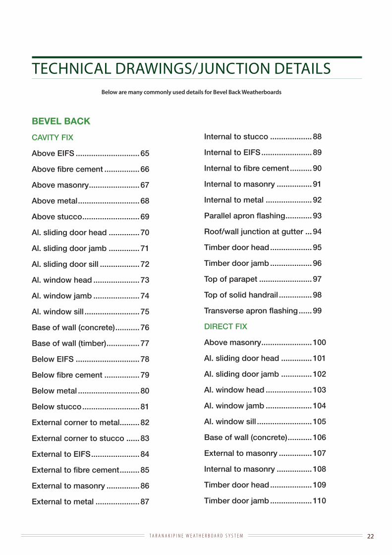
TECHNICAL DRAWINGS/JUNCTION DETAILSBelow are many commonly used details for Bevel Back Weatherboards
BEVEL BACK
CAVITY FIX
Above EIFS ............................. 65
Above fibre cement ................ 66
Above masonry ....................... 67
Above metal ............................ 68
Above stucco .......................... 69
Al. sliding door head .............. 70
Al. sliding door jamb .............. 71
Al. sliding door sill .................. 72
Al. window head ..................... 73
Al. window jamb ..................... 74
Al. window sill ......................... 75
Base of wall (concrete) ........... 76
Base of wall (timber) ............... 77
Below EIFS ............................. 78
Below fibre cement ................ 79
Below metal ............................ 80
Below stucco .......................... 81
External corner to metal ......... 82
External corner to stucco ...... 83
External to EIFS ...................... 84
External to fibre cement ......... 85
External to masonry ............... 86
External to metal .................... 87
Internal to stucco ................... 88
Internal to EIFS ....................... 89
Internal to fibre cement .......... 90
Internal to masonry ................ 91
Internal to metal ..................... 92
Parallel apron flashing ............ 93
Roof/wall junction at gutter ... 94
Timber door head ................... 95
Timber door jamb ................... 96
Top of parapet ........................ 97
Top of solid handrail ............... 98
Transverse apron flashing ...... 99
DIRECT FIX
Above masonry ....................... 100
Al. sliding door head .............. 101
Al. sliding door jamb .............. 102
Al. window head ..................... 103
Al. window jamb ..................... 104
Al. window sill ......................... 105
Base of wall (concrete) ........... 106
External to masonry ............... 107
Internal to masonry ................ 108
Timber door head ................... 109
Timber door jamb ................... 110

T A R A N A K I P I N E W E A T H E R B O A R D S Y S T E M 23
TECHNICAL DRAWINGS/JUNCTION DETAILSBelow are many commonly used details for Rusticated Weatherboards
RUSTICATED
CAVITY FIX
Above EIFS ............................. 115
Above fibre cement ................ 116
Above masonry ....................... 117
Above metal ............................ 118
Above stucco .......................... 119
Al. sliding door head .............. 120
Al. sliding door jamb .............. 121
Al. sliding door sill .................. 122
Al. window head ..................... 123
Al. window jamb ..................... 124
Al. window sill ......................... 125
Base of wall (concrete) ........... 126
Base of wall (timber) ............... 127
Below EIFS ............................. 128
Below fibre cement ................ 129
Below metal ............................ 130
Below stucco .......................... 131
External corner to metal ......... 132
External corner to stucco ...... 133
External to EIFS ...................... 134
External to fibre cement ......... 135
External to masonry ............... 136
External to metal .................... 137
Internal to stucco ................... 138
Internal to EIFS ....................... 139
Internal to fibre cement .......... 140
Internal to masonry ................ 141
Internal to metal ..................... 142
Parallel apron flashing ............ 143
Roof/wall junction at gutter ... 144
Timber door head ................... 145
Timber door jamb ................... 146
Top of parapet ........................ 147
Top of solid handrail ............... 148
Transverse apron flashing ...... 149
DIRECT FIX
Above masonry ....................... 150
Al. sliding door head .............. 151
Al. sliding door jamb .............. 152
Al. window head ..................... 153
Al. window jamb ..................... 154
Al. window sill ......................... 155
Base of wall (concrete) ........... 156
External to masonry ............... 157
Internal to masonry ................ 158
Timber door head ................... 159
Timber door jamb ................... 160
T A R A N A K I P I N E W E A T H E R B O A R D S Y S T E M 24
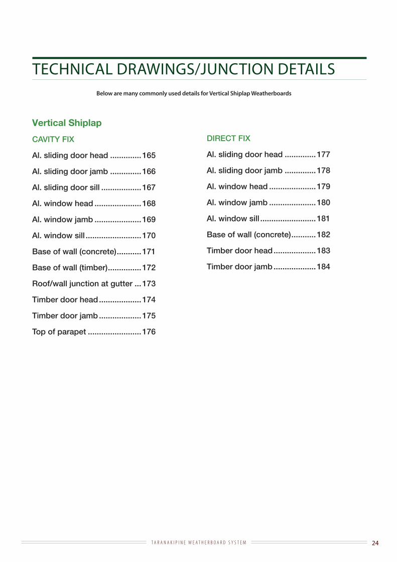
TECHNICAL DRAWINGS/JUNCTION DETAILSBelow are many commonly used details for Vertical Shiplap Weatherboards
Vertical Shiplap
CAVITY FIX
Al. sliding door head .............. 165
Al. sliding door jamb .............. 166
Al. sliding door sill .................. 167
Al. window head ..................... 168
Al. window jamb ..................... 169
Al. window sill ......................... 170
Base of wall (concrete) ........... 171
Base of wall (timber) ............... 172
Roof/wall junction at gutter ... 173
Timber door head ................... 174
Timber door jamb ................... 175
Top of parapet ........................ 176
DIRECT FIX
Al. sliding door head .............. 177
Al. sliding door jamb .............. 178
Al. window head ..................... 179
Al. window jamb ..................... 180
Al. window sill ......................... 181
Base of wall (concrete) ........... 182
Timber door head ................... 183
Timber door jamb ................... 184
25T A R A N A K I P I N E W E A T H E R B O A R D S Y S T E M
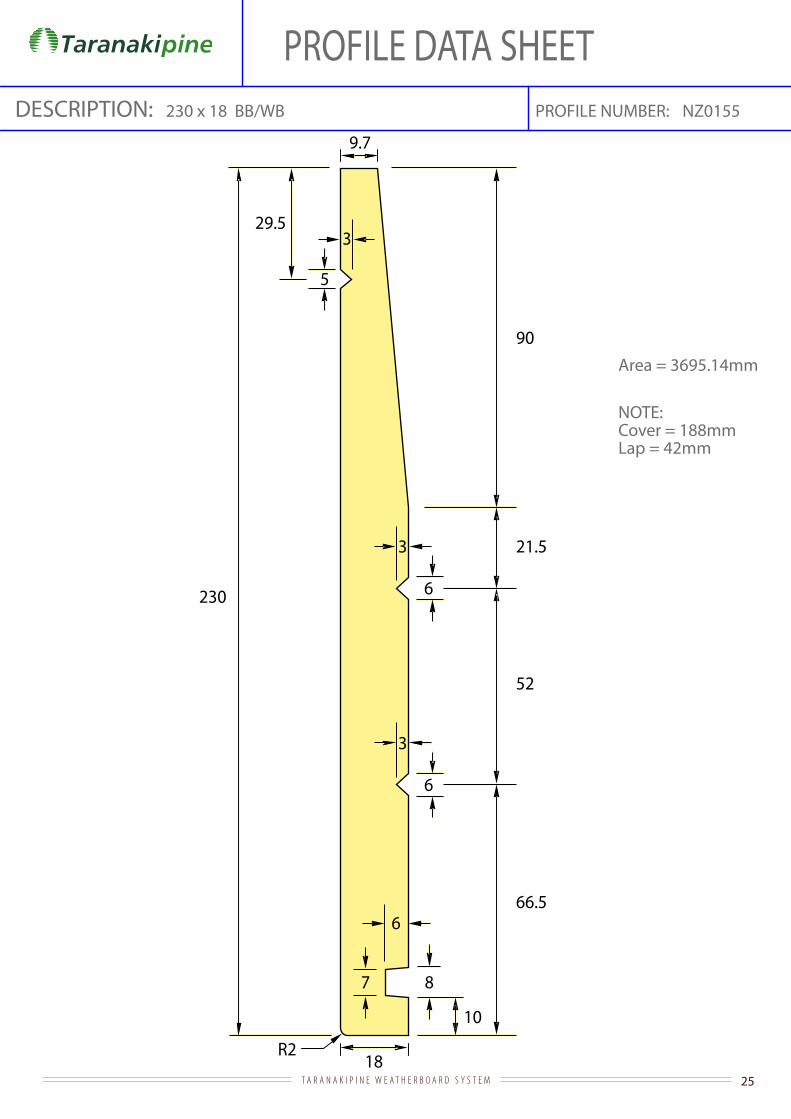
PROFILE DATA SHEETPROFILE NUMBER:DESCRIPTION: NZ0155
Area = 3695.14mm
NOTE:Cover = 188mmLap = 42mm
230 x 18 BB/WB
R2
230
29.5
5
3
9.7
8
10
66.56
7
21.5
18
6
3
6
3
52
90
26T A R A N A K I P I N E W E A T H E R B O A R D S Y S T E M
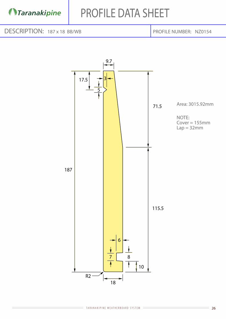
PROFILE DATA SHEETPROFILE NUMBER:DESCRIPTION: NZ0154
Area: 3015.92mm
NOTE:Cover = 155mmLap = 32mm
187 x 18 BB/WB
R2
187
17.5
5
3
9.7
8
10
115.5
6
7
71.5
18

27T A R A N A K I P I N E W E A T H E R B O A R D S Y S T E M
PROFILE DATA SHEETPROFILE NUMBER:DESCRIPTION: NZ0120
Area: 2980.07mm
NOTE:Cover = 148mmLap = 32mm
180 x 18.5 BB/WB
R3
180 161
6
10
4
18.5
19
6
3
9.5
110
70

28T A R A N A K I P I N E W E A T H E R B O A R D S Y S T E M
PROFILE DATA SHEETPROFILE NUMBER:DESCRIPTION: NZ0153
Area: 2292.24mm
NOTE:Cover = 110mmLap = 32mm
142 x 18 BB/WB
R2
142
17.5
5
3
9.7
8
10
91.3
6
7
50.7
18

29T A R A N A K I P I N E W E A T H E R B O A R D S Y S T E M
PROFILE DATA SHEET
Area = 2237.57mm
DESCRIPTION: 135 X 18.5 bb/wb 0121PROFILE NUMBER:
R3
135
19
116
6
3
9.5
50
6
10
85
4
18.5
NOTE:Cover = 103mmLap = 32mm

30T A R A N A K I P I N E W E A T H E R B O A R D S Y S T E M
Area = 3342.53mm
PROFILE DATA SHEETPROFILE NUMBER:DESCRIPTION: NZ0123225x18 F/J Scalloped Rustic
71225
73
918
R3
10
6
11
54
4
9 9
6
3
3.5
R25
67
19
18
175

31T A R A N A K I P I N E W E A T H E R B O A R D S Y S T E M
PROFILE DATA SHEETPROFILE NUMBER:180x18.5 F/J Scolloped Rustic W/B 1979
Area = 2604.84mm
0090
R3
10
6
11 4
9 9.5
R25
9
57
6
3
67
19
18
60
36
180
DESCRIPTION:
32T A R A N A K I P I N E W E A T H E R B O A R D S Y S T E M
R25
R3
9
10
6
11
19
32
57
6
3
135
67
19
18
4
9 9.5
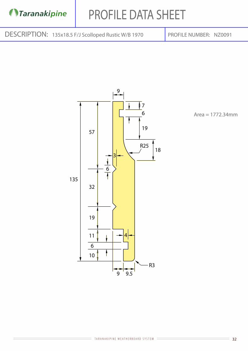
PROFILE DATA SHEETPROFILE NUMBER:135x18.5 F/J Scolloped Rustic W/B 1970
Area = 1772.34mm
NZ0091DESCRIPTION:
33T A R A N A K I P I N E W E A T H E R B O A R D S Y S T E M
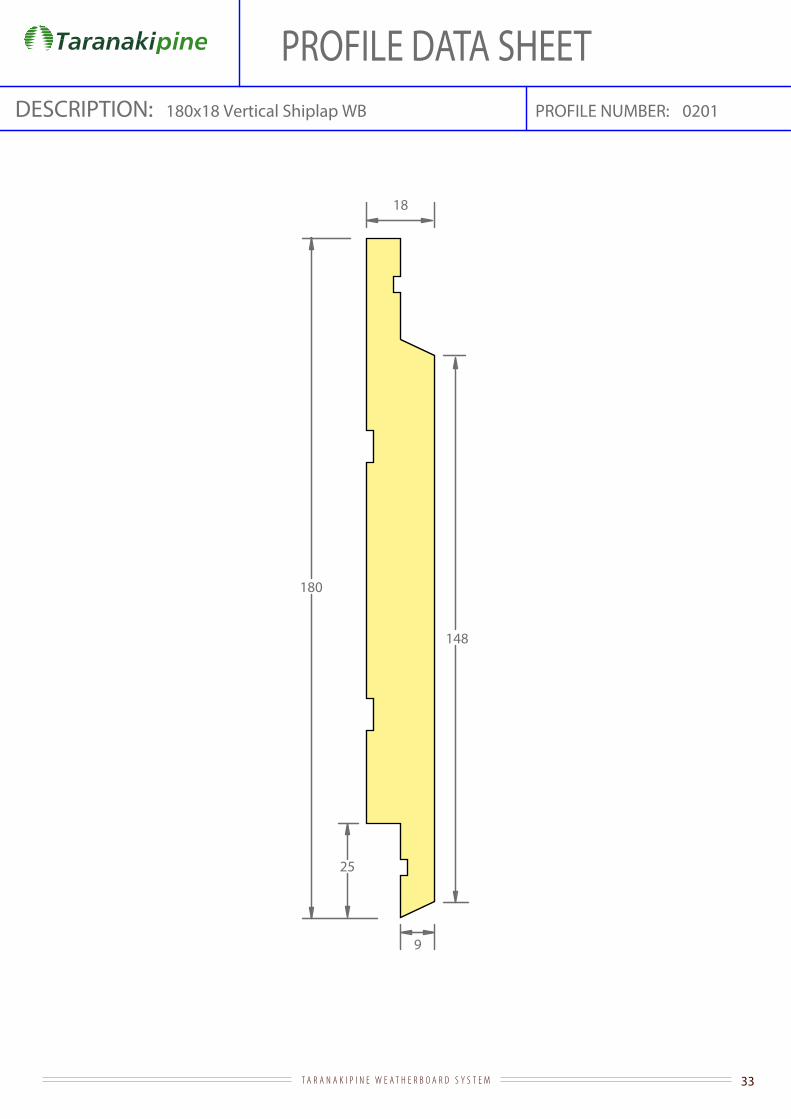
PROFILE DATA SHEETPROFILE NUMBER:180x18 Vertical Shiplap WB 0201DESCRIPTION:
25
148
180
9
18
34T A R A N A K I P I N E W E A T H E R B O A R D S Y S T E M
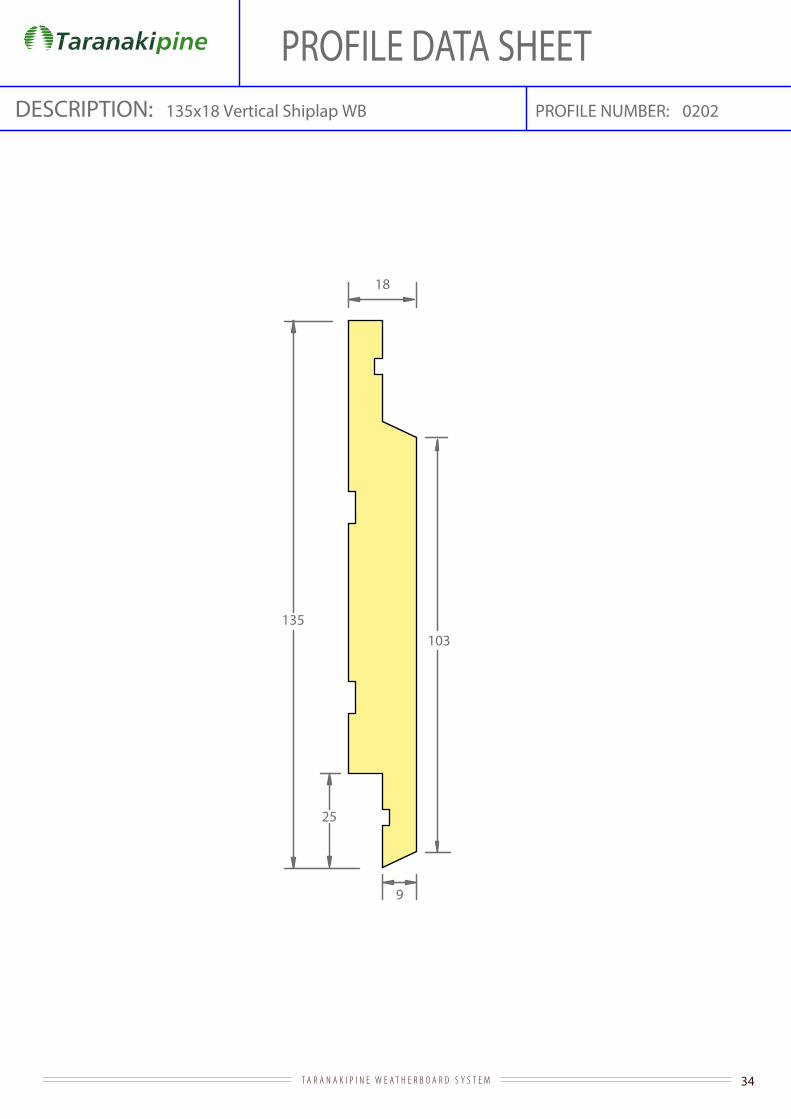
PROFILE DATA SHEETPROFILE NUMBER:135x18 Vertical Shiplap WB 0202DESCRIPTION:
25
103135
9
18

35T A R A N A K I P I N E W E A T H E R B O A R D S Y S T E M
PROFILE DATA SHEETPROFILE NUMBER:DESCRIPTION: 18mm Quad NZ0009
Area = 251.38mm
R18
13
10
25
46.7°

36T A R A N A K I P I N E W E A T H E R B O A R D S Y S T E M
R5
40
10
PROFILE NUMBER:DESCRIPTION: 40 x 10 Scriber NZ0172
Area = 389.27mm
PROFILE DATA SHEET
37T A R A N A K I P I N E W E A T H E R B O A R D S Y S T E M
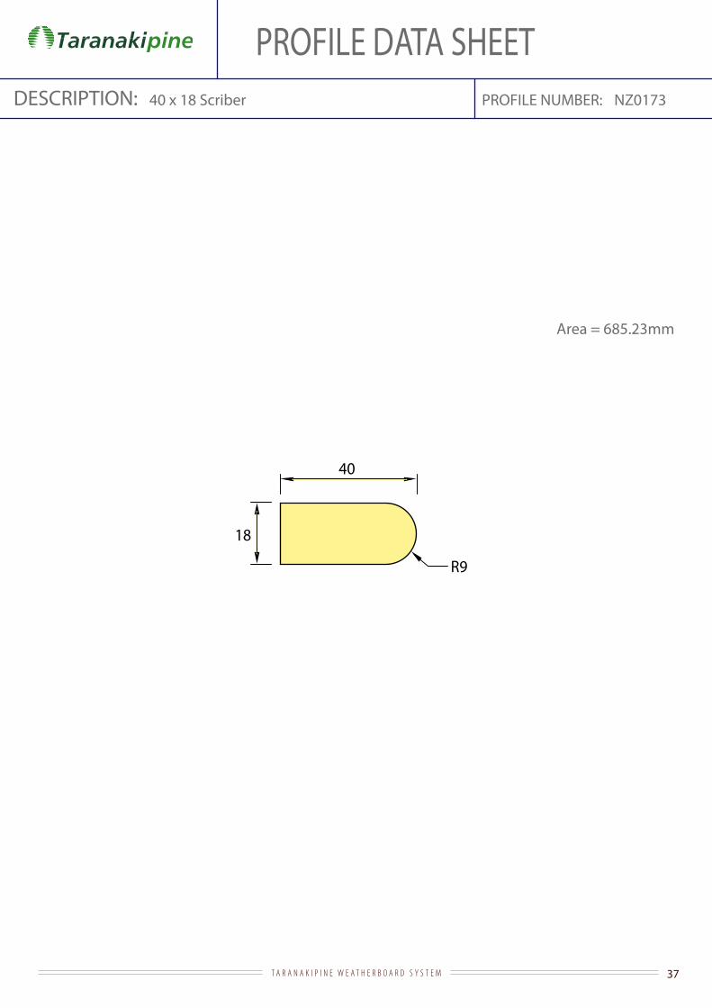
R9
40
18
PROFILE NUMBER:DESCRIPTION: 40 x 18 Scriber NZ0173
Area = 685.23mm
PROFILE DATA SHEET

38T A R A N A K I P I N E W E A T H E R B O A R D S Y S T E M
PROFILE DATA SHEETPROFILE NUMBER:DESCRIPTION: NZ016225 x 18 Eaves Mould
25
18
5
Area: 320.87mm

39T A R A N A K I P I N E W E A T H E R B O A R D S Y S T E M
PROFILE DATA SHEETPROFILE NUMBER:DESCRIPTION: 42x42 DAR 2mm P/RND 3083
42
42
R2
Area = 1761mm

40T A R A N A K I P I N E W E A T H E R B O A R D S Y S T E M
35.8
5
121
48
138
5
34° 34°
34°
65
49
49
R3
R356
3.5
5
15.5
63.5
3
37
PROFILE NUMBER:DESCRIPTION: 138 x 19 E&CB 130 Cover 802
Area = 2389.58mm
PROFILE DATA SHEET

41T A R A N A K I P I N E W E A T H E R B O A R D S Y S T E M
PROFILE DATA SHEETPROFILE NUMBER:DESCRIPTION: NZ004518mm Eaves Mould
Area = 320.87mm
18
18
5
42T A R A N A K I P I N E W E A T H E R B O A R D S Y S T E M
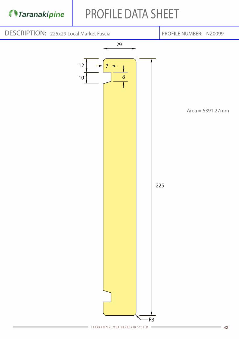
PROFILE DATA SHEETPROFILE NUMBER:DESCRIPTION:
Area = 6391.27mm
225x29 Local Market Fascia NZ0099
225
R3
29
7
8
12
10
43T A R A N A K I P I N E W E A T H E R B O A R D S Y S T E M
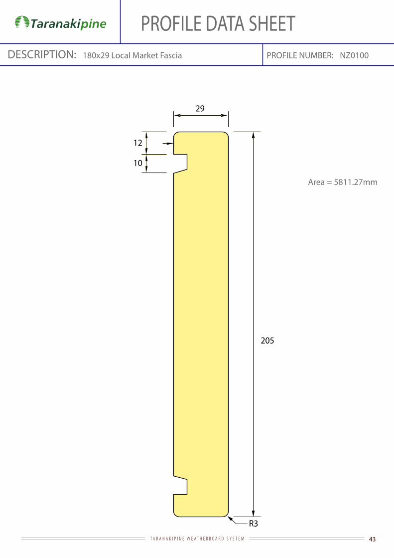
PROFILE DATA SHEETPROFILE NUMBER:DESCRIPTION:
Area = 5811.27mm
180x29 Local Market Fascia NZ0100
205
R3
29
7
8
12
10
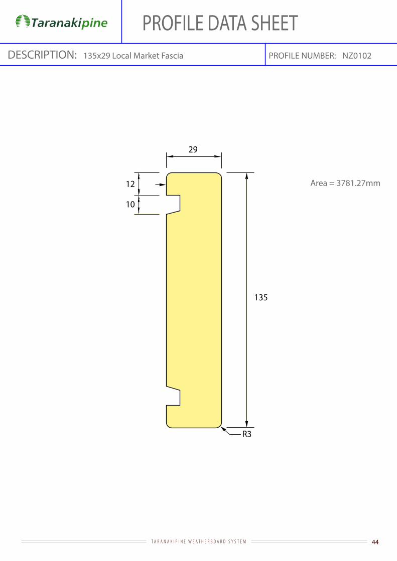
44T A R A N A K I P I N E W E A T H E R B O A R D S Y S T E M
PROFILE DATA SHEETPROFILE NUMBER:DESCRIPTION:
Area = 3781.27mm
135x29 Local Market Fascia NZ0102
135
R3
29
7
8
12
10

45T A R A N A K I P I N E W E A T H E R B O A R D S Y S T E M
225
R3
7
8
12
10
18
Area = 3916.27mm
225x18 Local Market Fascia NZ0103PROFILE NUMBER:DESCRIPTION:
PROFILE DATA SHEET

46T A R A N A K I P I N E W E A T H E R B O A R D S Y S T E M
PROFILE DATA SHEET
Area = 3106.27mm
180x18 Local Market Fascia NZ0104PROFILE NUMBER:DESCRIPTION:
180
R3
18
7
8
12
10

47T A R A N A K I P I N E W E A T H E R B O A R D S Y S T E M
Area = 2296.27mm
135x18 Local Market Fascia NZ0105PROFILE NUMBER:DESCRIPTION:
135
R3
18
7
8
12
10
PROFILE DATA SHEET
48T A R A N A K I P I N E W E A T H E R B O A R D S Y S T E M
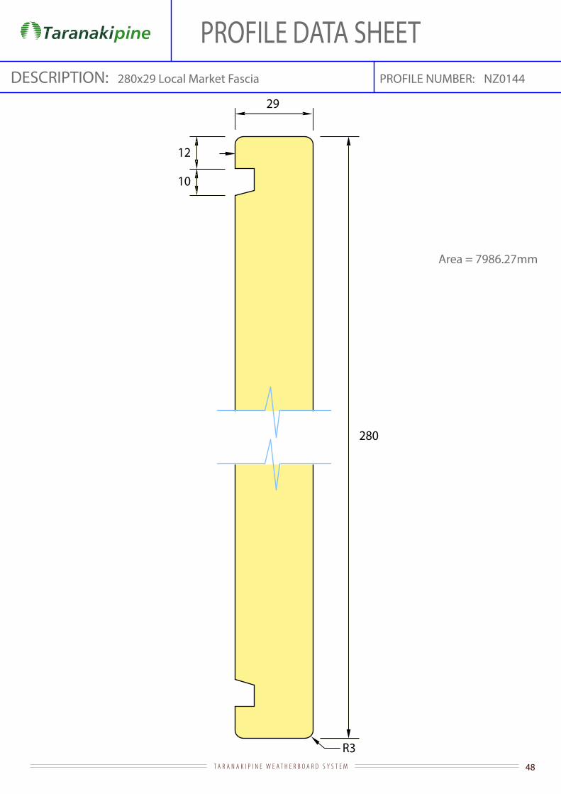
PROFILE DATA SHEETPROFILE NUMBER:DESCRIPTION:
Area = 7986.27mm
280x29 Local Market Fascia NZ0144
280
R3
29
7
8
12
10

49T A R A N A K I P I N E W E A T H E R B O A R D S Y S T E M
PROFILE DATA SHEETPROFILE NUMBER:DESCRIPTION: 44x21 Cavity Batten
44
22
Area = 968mm

50T A R A N A K I P I N E W E A T H E R B O A R D S Y S T E M
PROFILE DATA SHEETPROFILE NUMBER:DESCRIPTION: 138x18 Grooved Facing NZ0545
Area = 2339.03mm9
11
138
7 9
11
79
18
98
R1.5

51T A R A N A K I P I N E W E A T H E R B O A R D S Y S T E M
PROFILE DATA SHEETPROFILE NUMBER:DESCRIPTION:
Area = 4906.27mm
280 x 18 Local Market Fascia NZ0148
280
R3
7
8
12
10
18

52T A R A N A K I P I N E W E A T H E R B O A R D S Y S T E M
PROFILE DATA SHEETPROFILE NUMBER:DESCRIPTION: 24 x 9 Rustic Plug NZ0161
Area = 163.28mm
R25
9
24
4.8
(Suits NZ0090 / NZ0091 / NZ0123)
53T A R A N A K I P I N E W E A T H E R B O A R D S Y S T E M
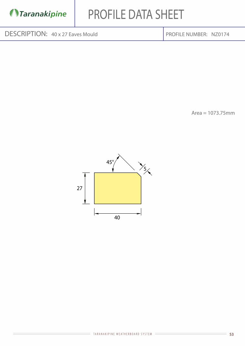
40
27
545°
PROFILE NUMBER:DESCRIPTION: 40 x 27 Eaves Mould NZ0174
Area = 1073.75mm
PROFILE DATA SHEET

54T A R A N A K I P I N E W E A T H E R B O A R D S Y S T E M
R9
60
18
PROFILE NUMBER:DESCRIPTION: 60 x 18 Scriber NZ0175
Area = 1045.23mm
PROFILE DATA SHEET
55T A R A N A K I P I N E W E A T H E R B O A R D S Y S T E M
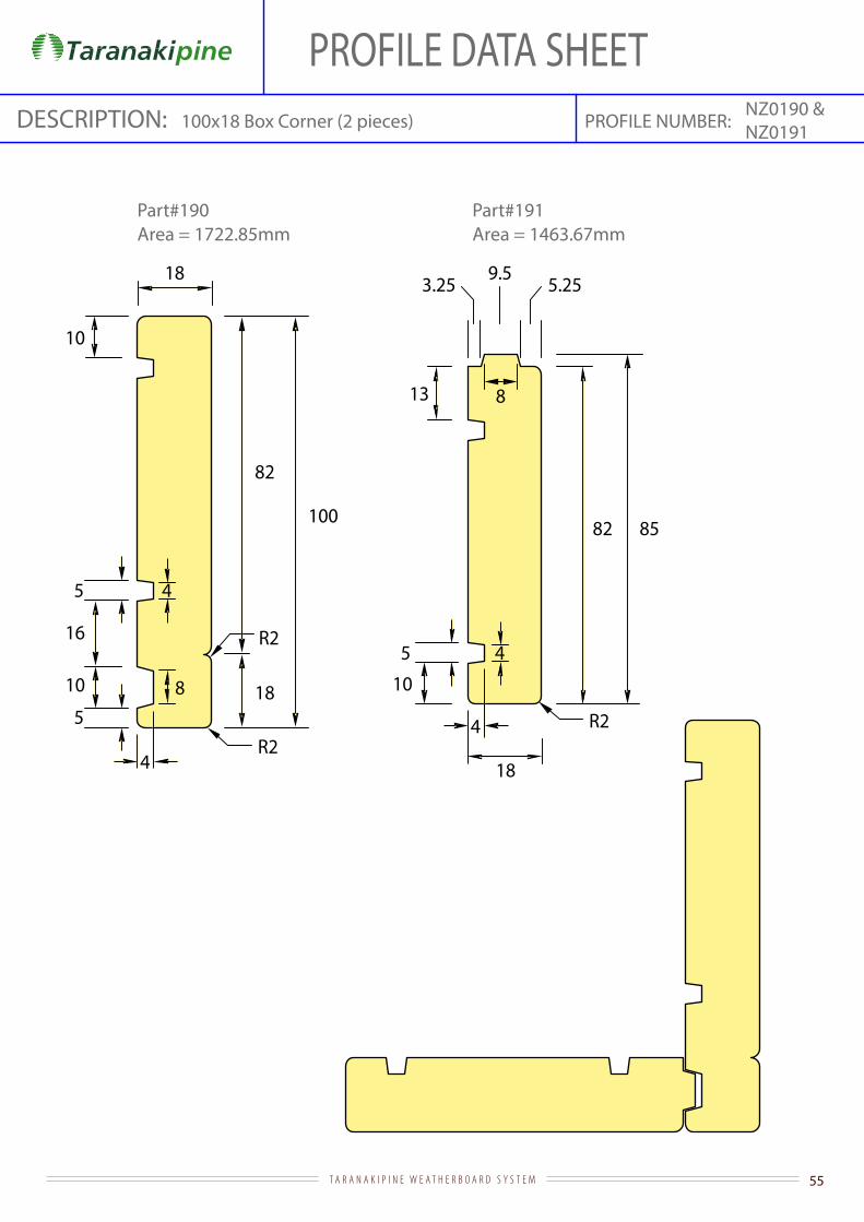
PROFILE DATA SHEETPROFILE NUMBER:DESCRIPTION: NZ0190 &
NZ0191100x18 Box Corner (2 pieces)
10
5 4
13
R2
5.253.25 9.5
8
82 85
5 4
10 8
4
45
10
18
18
R2
R2
82
100
18
16
Part#190 Part#191Area = 1722.85mm Area = 1463.67mm
56T A R A N A K I P I N E W E A T H E R B O A R D S Y S T E M
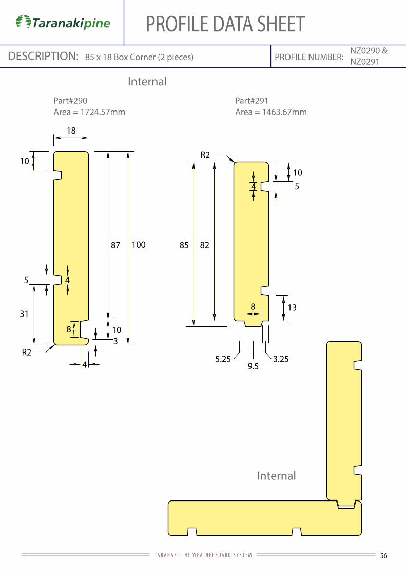
NZ0290 &NZ0291
85 82
R2
1054
13
3.255.259.5
8
5 4
10
18
R2
100
8 103
87
31
4
Internal
Internal
PROFILE NUMBER:DESCRIPTION: 85 x 18 Box Corner (2 pieces)
Area = 1724.57mm
PROFILE DATA SHEET
Part#290 Part#291Area = 1463.67mm
57T A R A N A K I P I N E W E A T H E R B O A R D S Y S T E M
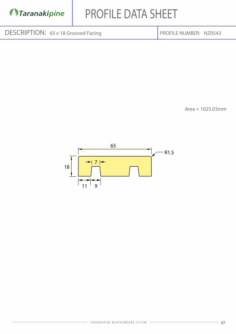
65
187
11 9
R1.5
PROFILE NUMBER:DESCRIPTION: 65 x 18 Grooved Facing NZ0543
Area = 1025.03mm
PROFILE DATA SHEET

58T A R A N A K I P I N E W E A T H E R B O A R D S Y S T E M
90
187
11 9
R1.5
7
PROFILE NUMBER:DESCRIPTION: 90 x 18 Grooved Facing NZ0544
Area = 1475.03mm
PROFILE DATA SHEET

59T A R A N A K I P I N E W E A T H E R B O A R D S Y S T E M
185
18
79
11
R1.5
7
PROFILE NUMBER:DESCRIPTION: 185 x 18 Grooved Facing NZ0546
Area = 3185.03mm
PROFILE DATA SHEET

60T A R A N A K I P I N E W E A T H E R B O A R D S Y S T E M
65
6
1052
37
PROFILE NUMBER:DESCRIPTION: 65 x 37 Sill Block NZ0163
Area = 2138.78mm
PROFILE DATA SHEET
70.6°
61T A R A N A K I P I N E W E A T H E R B O A R D S Y S T E M
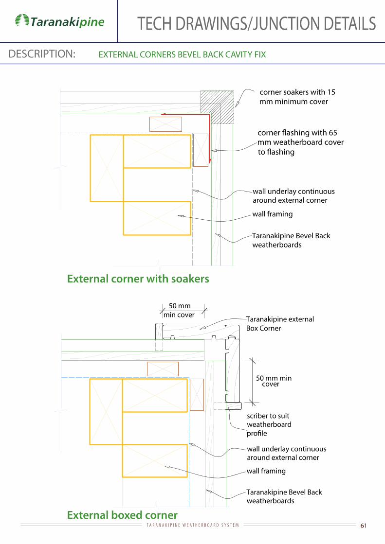
DESCRIPTION: EXTERNAL CORNERS BEVEL BACK CAVITY FIX
External corner with soakers
wall framing
wall underlay continuousaround external corner
Taranakipine Bevel Back weatherboards
corner soakers with 15 mm minimum cover
External boxed corner
wall framing
wall underlay continuousaround external corner
Taranakipine Bevel Back weatherboards
Taranakipine externalBox Corner
50 mm min cover
scriber to suitweatherboard
50 mm mincover
mm weatherboard cover
TECH DRAWINGS/JUNCTION DETAILS

62T A R A N A K I P I N E W E A T H E R B O A R D S Y S T E M
DESCRIPTION: EXTERNAL CORNERS BEVEL BACK DIRECT FIX
wall framing
wall underlay continuousaround external corner
65 mm
65 mm
corner soakers with 15 mm minimum cover
mm weatherboard cover
External corner with soakers
Taranakipine Bevel Back weatherboards
wall framing
wall underlaycontinuous around external corner
Taranakipine externalBox Corner
50 mm min cover
scriber to suit weatherboard
50 mm mincover
External boxed corner
Taranakipine Bevel Back weatherboards
TECH DRAWINGS/JUNCTION DETAILS
63T A R A N A K I P I N E W E A T H E R B O A R D S Y S T E M
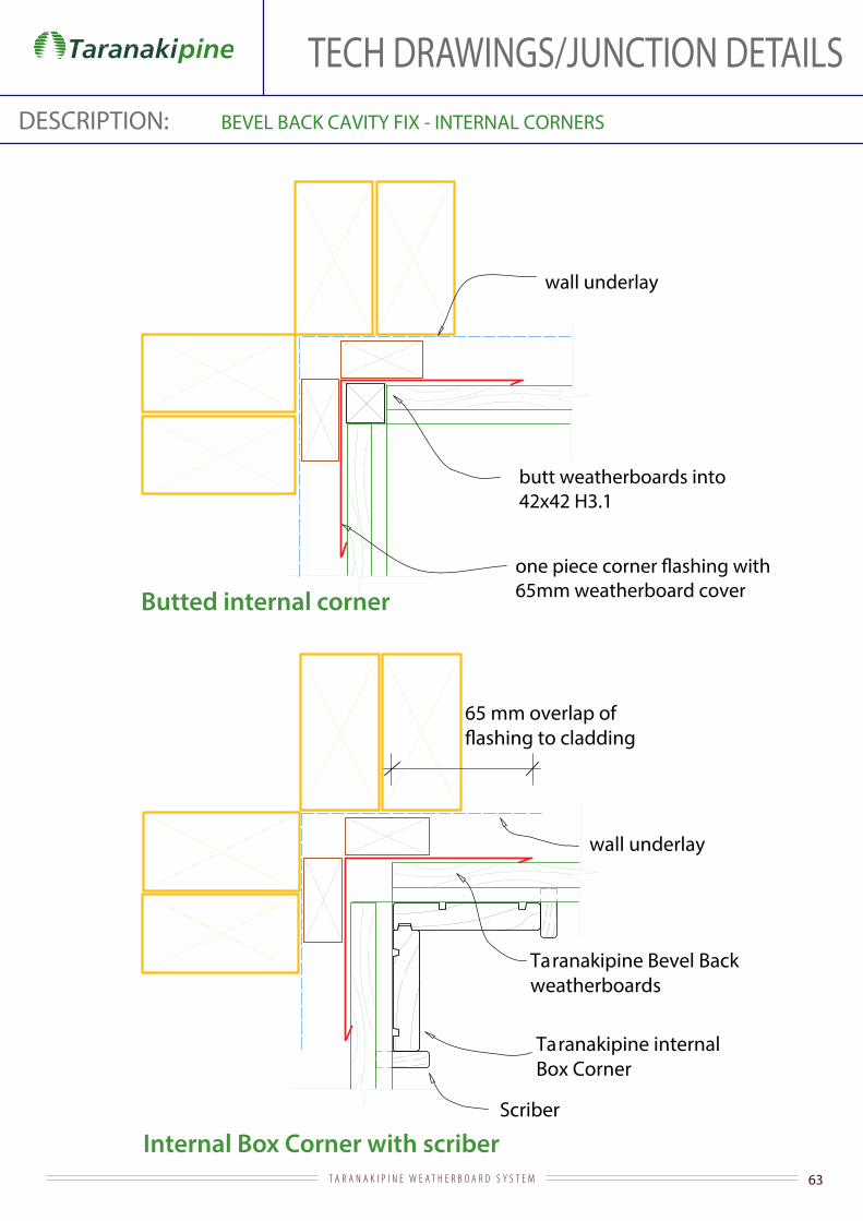
DESCRIPTION: BEVEL BACK CAVITY FIX - INTERNAL CORNERS
65mm weatherboard cover
butt weatherboards into42x42 H3.1
wall underlay
Butted internal corner
Taranakipine internalBox Corner
Scriber
Taranakipine Bevel Backweatherboards
65 mm overlap of
wall underlay
Internal Box Corner with scriber
TECH DRAWINGS/JUNCTION DETAILS

64T A R A N A K I P I N E W E A T H E R B O A R D S Y S T E M
DESCRIPTION: BEVEL BACK DIRECT FIX - INTERNAL CORNERS
65mm weatherboard cover
butt weatherboards into42x42 H3.1
wall underlay
Butted internal corner
Internal Box Corner with scriber
Taranakipine internalBox Corner
Scriber
Taranakipine Bevel Backweatherboards
65 mm overlap of
wall underlay
TECH DRAWINGS/JUNCTION DETAILS
65T A R A N A K I P I N E W E A T H E R B O A R D S Y S T E M
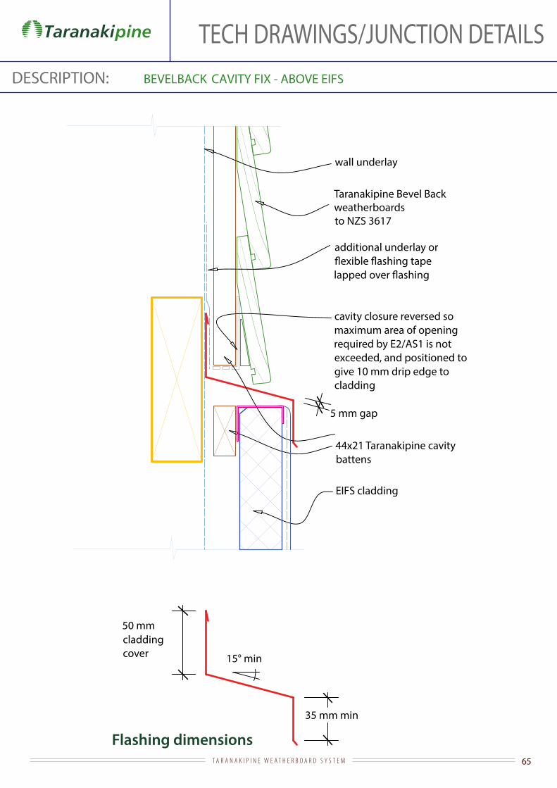
TECH DRAWINGS/JUNCTION DETAILSDESCRIPTION: BEVELBACK
Flashing dimensions
CAVITY FIX - ABOVE EIFS
cavity closure reversed so maximum area of opening required by E2/AS1 is not exceeded, and positioned to give 10 mm drip edge to cladding
44x21 Taranakipine cavity battens
EIFS cladding
wall underlay
Taranakipine Bevel Back weatherboards to NZS 3617
additional underlay or
50 mm cladding cover
35 mm min
15° min
5 mm gap

66T A R A N A K I P I N E W E A T H E R B O A R D S Y S T E M
TECH DRAWINGS/JUNCTION DETAILSDESCRIPTION: BEVELBACK
Flashing dimensions
CAVITY FIX - ABOVE FIBRE CEMENT
50 mm cladding cover
35 mm min
15° min
cavity closure reversed so maximum area of opening required by E2/AS1 is not exceeded, and positioned to give 10 mm drip edge to cladding
44x21 Taranakipine cavity battens
wall underlay
Taranakipine Bevel Back weatherboards to NZS 3617
additional underlay or
5 mm gap

67T A R A N A K I P I N E W E A T H E R B O A R D S Y S T E M
TECH DRAWINGS/JUNCTION DETAILSDESCRIPTION: BEVELBACK CAVITY FIX - ABOVE MASONRY
Flashing dimensions
leave every 3rd perpend open for ventilation in course under sill brick
50 mm cladding cover 15° min
20 mm
50 mm
sill brick
mortar
cavity closure reversed so maximum area of opening required by E2/AS1 is not exceeded, and positioned to give 10 mm drip edge to cladding
44x21 Taranakipine cavity battens
EIFS cladding
wall underlay
Taranakipine Bevel Back weatherboards to NZS 3617
additional underlay or
5 mm gap

68T A R A N A K I P I N E W E A T H E R B O A R D S Y S T E M
TECH DRAWINGS/JUNCTION DETAILSDESCRIPTION: BEVELBACK CAVITY FIX - ABOVE METAL
Flashing dimensions
50 mm cladding cover 15° min
dimension for overlapto be over 1 1
2 crests
cavity closure reversed so maximum area of opening required by E2/AS1 is not exceeded, and positioned to give 10 mm drip edge to cladding
44x21 Taranakipine cavity battens
wall underlay
Taranakipine Bevel Back weatherboards to NZS 3617
additional underlay or
5 mm gap

69T A R A N A K I P I N E W E A T H E R B O A R D S Y S T E M
TECH DRAWINGS/JUNCTION DETAILSDESCRIPTION: BEVELBACK CAVITY FIX - ABOVE STUCCO
Flashing dimensions
stucco on backing (non-rigid or rigid on slip layer)
50 mm cladding cover
35 mm min
15° min
cavity closure reversed so maximum area of opening required by E2/AS1 is not exceeded, and positioned to give 10 mm drip edge to cladding
44x21 Taranakipine cavity battens
wall underlay
Taranakipine Bevel Back weatherboards to NZS 3617
additional underlay or
5 mm gap

70T A R A N A K I P I N E W E A T H E R B O A R D S Y S T E M
TECH DRAWINGS/JUNCTION DETAILSDESCRIPTION: BEVELBACK CAVITY FIX - ALUMINIUM SLIDING DOOR HEAD
Flashing dimensions
Taranakipine Bevel Back weatherboard to NZS 3617
stop-ended and extended to edge of aluminium jamb facing
internal lining
35 mm facings
air seal over backing rod
additional underlay or
44x21 Taranakipine cavity battens
wall underlay dressed into
at corners
timber slimline reveal (or architrave)
cavity base closure positioned to give
15 mm min drip edge to cladding
weatherboard - shape to shed water with drip to bottom edge and project
15 mm past scriber
5 mm gap
against aluminium head facing
50 mm cladding cover
15° min
10 mm stop-end
10 mm min

71T A R A N A K I P I N E W E A T H E R B O A R D S Y S T E M
TECH DRAWINGS/JUNCTION DETAILSDESCRIPTION: BEVELBACK CAVITY FIX - ALUMINIUM SLIDING DOOR JAMB
Taranakipine Bevel Back weatherboard
internal lining
line of weatherhead over
19 mm min continuous jamb packing
air seal over backing rod
with 35 mm facings
wall underlay dressed
44x21 Taranakipine cavity battens
timber slimline reveal (or architrave)
scriber extending to underside of weatherhead
15 mm

72T A R A N A K I P I N E W E A T H E R B O A R D S Y S T E M
TECH DRAWINGS/JUNCTION DETAILSDESCRIPTION: BEVELBACK CAVITY FIX - ALUMINIUM SLIDING DOOR SILL
cavity closure positioned to give 10 mm drip edge to cladding
Taranakipine Bevel Back weatherboards
air seal
timber packer
blocking to
boundary joists reduced in size
aluminium door sill with 35 mm facing
wall underlay dressed into
tape over full width of sill and turned up 100 mm at corners
44x21 Taranakipine cavity battens50
support bracket (as required by door manufacturer)
continuous jamb packer shown dotted
dpc
timber sill
timber trim

73T A R A N A K I P I N E W E A T H E R B O A R D S Y S T E M
TECH DRAWINGS/JUNCTION DETAILSDESCRIPTION: BEVELBACK CAVITY FIX - ALUMINIUM WINDOW HEAD
Taranakipine Bevel Back weatherboard
stop-ended and extended to edge of aluminium jamb facing
internal lining
35 mm facings
air seal over backing rod
44x21 Taranakipine cavity battens
wall underlay dressed into
at corners
timber slimline reveal (or architrave)
of weatherhead and sealed
cavity base closure positioned to give
15 mm min drip edge to cladding
weatherboard - shape to shed water with drip to bottom edge and project
15 mm past scriber
5 mm gap
15° min
to head
10 mm stop-end to
10 mm min
50 mm cladding cover

74T A R A N A K I P I N E W E A T H E R B O A R D S Y S T E M
TECH DRAWINGS/JUNCTION DETAILSDESCRIPTION: BEVELBACK CAVITY FIX - ALUMINIUM WINDOW JAMB
Taranakipine Bevel Back weatherboard
internal lining
line of weatherhead over
19 mm min continuous jamb packer
air seal over backing rod
with 35 mm facings
wall underlay dressed
44x21 Taranakipine cavity battens
scriber extending to underside of weatherhead
timber slimline reveal (or architrave)
15 mm
75T A R A N A K I P I N E W E A T H E R B O A R D S Y S T E M
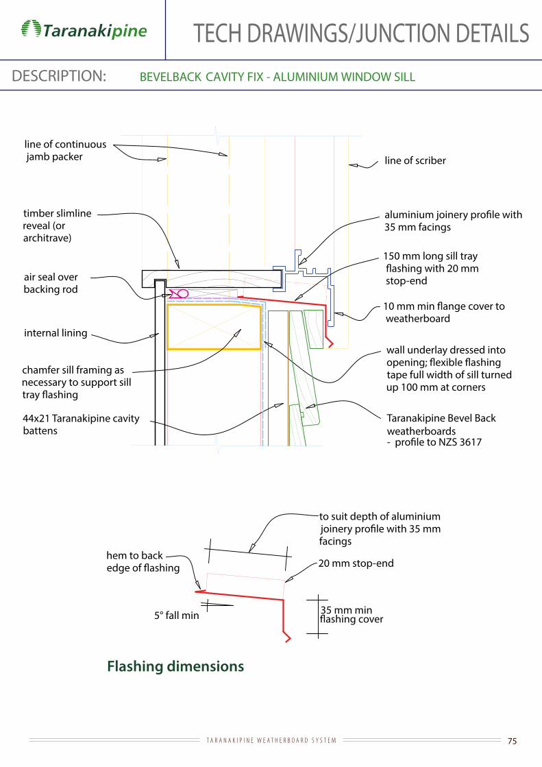
TECH DRAWINGS/JUNCTION DETAILSDESCRIPTION: BEVELBACK CAVITY FIX - ALUMINIUM WINDOW SILL
Flashing dimensions
wall underlay dressed into
tape full width of sill turned up 100 mm at corners
Taranakipine Bevel Back weatherboards
internal lining
44x21 Taranakipine cavity battens
line of continuous jamb packer
air seal over backing rod
chamfer sill framing as necessary to support sill
timber slimline reveal (or architrave)
5° fall min
20 mm stop-end hem to back
35 mm facings
line of scriber
150 mm long sill tray
stop-end
to suit depth of aluminium
facings
35 mm min
weatherboard

76T A R A N A K I P I N E W E A T H E R B O A R D S Y S T E M
TECH DRAWINGS/JUNCTION DETAILSDESCRIPTION: BEVELBACK CAVITY FIX - BASE OF WALL (CONCRETE)
ground level
internal lining
slab
foundation
50 mm
Taranakipine Bevel Back
to NZS 3617
44x21 Taranakipine cavity battens
wall underlaybottom plate on dpc cavity base closure positioned to give
10 mm drip edge to cladding and reversed so maximum area of opening required by E2/AS1 is not exceeded
100 mm min (paved)175 mm min (unpaved )

77T A R A N A K I P I N E W E A T H E R B O A R D S Y S T E M
TECH DRAWINGS/JUNCTION DETAILSDESCRIPTION: BEVELBACK CAVITY FIX - BASE OF WALL (TIMBER)
Taranakipine Bevel Back weatherboards to NZS 3617
boundary joists
wall underlay
44x21 Taranakipine cavity battens
50
cavity base closure positioned to give 10 mm drip edge to cladding and reversed so maximum area of opening required by E2/AS1 is not exceeded
wall plate on dpc
foundation wall
78T A R A N A K I P I N E W E A T H E R B O A R D S Y S T E M
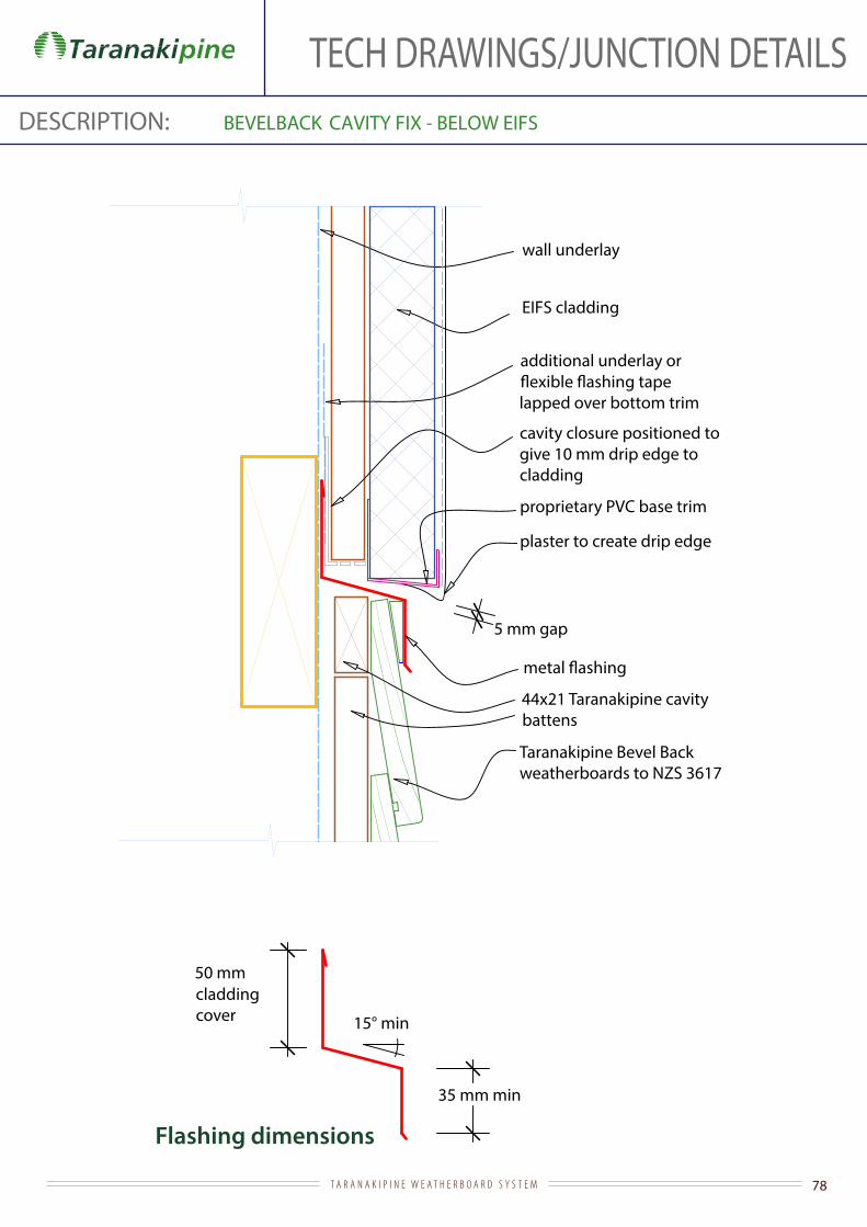
TECH DRAWINGS/JUNCTION DETAILSDESCRIPTION: BEVELBACK
Flashing dimensions
CAVITY FIX - BELOW EIFS
44x21 Taranakipine cavity battens
EIFS cladding
wall underlay
Taranakipine Bevel Back weatherboards to NZS 3617
additional underlay or
lapped over bottom trim
50 mm cladding cover
35 mm min
15° min
proprietary PVC base trim
plaster to create drip edge
cavity closure positioned to give 10 mm drip edge to cladding
5 mm gap
79T A R A N A K I P I N E W E A T H E R B O A R D S Y S T E M
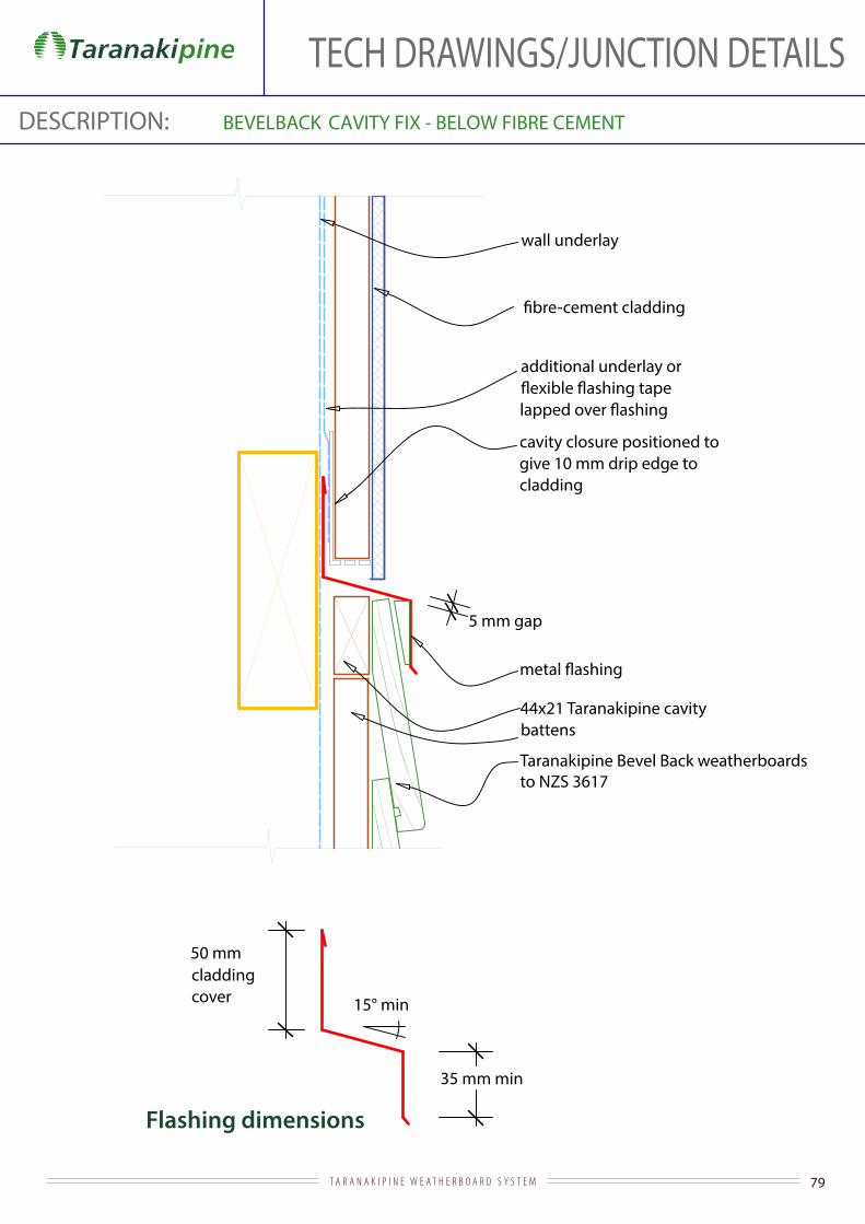
TECH DRAWINGS/JUNCTION DETAILSDESCRIPTION: BEVELBACK
Flashing dimensions
CAVITY FIX - BELOW FIBRE CEMENT
44x21 Taranakipine cavity battens
wall underlay
Taranakipine Bevel Back weatherboardsto NZS 3617
additional underlay or
50 mm cladding cover
35 mm min
15° min
cavity closure positioned to give 10 mm drip edge to cladding
5 mm gap

80T A R A N A K I P I N E W E A T H E R B O A R D S Y S T E M
TECH DRAWINGS/JUNCTION DETAILSDESCRIPTION: BEVELBACK CAVITY FIX - BELOW METAL
Flashing dimensions
44x21 Taranakipine cavity battens
wall underlay
Taranakipine Bevel Back weatherboards to NZS 3617
bottom trim
100 mm minupstand
35 mm min
15° min
cavity closure reversed so maximum area of opening required by E2/AS1 is not exceeded, and positioned to give 10 mm drip edge to cladding
5 mm gap

81T A R A N A K I P I N E W E A T H E R B O A R D S Y S T E M
TECH DRAWINGS/JUNCTION DETAILSDESCRIPTION: BEVELBACK
Flashing dimensions
form a drip edge and support bottom edge of plaster.
44x21 Taranakipine cavity battens
stucco on backing (non-rigid or rigid on slip layer)
wall underlay
Taranakipine Bevel Back weatherboards to NZS 3617
additional underlay or
upstand
50 mm cladding cover
35 mm min
15° min
cavity closure positioned to give 10 mm drip edge to cladding
5 mm gap
CAVITY FIX - BELOW STUCCO

82T A R A N A K I P I N E W E A T H E R B O A R D S Y S T E M
TECH DRAWINGS/JUNCTION DETAILSDESCRIPTION: BEVELBACK
Flashing dimensions
wall framing
wall underlay continuous around external corner
Taranakipine Bevel Back weatherboards
115 x 19 and 90 x 19 Taranakipine grooved facing or alternatively Taranakipine external Box Corner
scriber to suit
gap (10 mm recommended)
65 mm
100 mm cladding cover
cladding cover
CAVITY FIX - EXTERNAL CORNER TO METAL

83T A R A N A K I P I N E W E A T H E R B O A R D S Y S T E M
TECH DRAWINGS/JUNCTION DETAILSDESCRIPTION: BEVELBACK CAVITY FIX - EXTERNAL CORNER TO STUCCO
stucco on backing (non-rigid or rigid on slip layer)
wall framing
wall underlay continuous around external corner
Taranakipine Bevel Back weatherboards scriber to suit
115 x 19 and 90 x 19 Taranakipine grooved facing or alternatively Taranakipine external Box Corner
44x21 Taranakipine cavity battens at 400 crs

84T A R A N A K I P I N E W E A T H E R B O A R D S Y S T E M
TECH DRAWINGS/JUNCTION DETAILSDESCRIPTION: BEVELBACK CAVITY FIX - EXTERNAL TO EIFS
EIFS cladding
wall framing
wall underlay continuous around external corner
Taranakipine Bevel Back weatherboards
scriber to suit
115 x 19 and 90 x 19 Taranakipine grooved facing or alternatively Taranakipine external Box Corner
44x21 Taranakipine cavity battens

85T A R A N A K I P I N E W E A T H E R B O A R D S Y S T E M
TECH DRAWINGS/JUNCTION DETAILSDESCRIPTION: BEVELBACK CAVITY FIX - EXTERNAL TO FIBRE CEMENT
wall framing
wall underlay continuous around external corner
Taranakipine Bevel Back weatherboards
scriber to suit
115 x 19 and 90 x 19 Taranakipine grooved facing or alternatively Taranakipine external Box Corner
44x21 Taranakipine cavity battens

86T A R A N A K I P I N E W E A T H E R B O A R D S Y S T E M
TECH DRAWINGS/JUNCTION DETAILSDESCRIPTION: BEVELBACK CAVITY FIX - EXTERNAL TO MASONRY
wall framing
wall underlay continuous around external corner
Taranakipine Bevel Back weatherboards
sealant over backing rod
masonry veneer
scriber to suit weatherboard
20 mm
40 - 75 mm
edge of slab (provide nib to support end of veneer wall)
90 x 19 Taranakipine grooved facing
44 x 21 Taranakipine cavity battens

87T A R A N A K I P I N E W E A T H E R B O A R D S Y S T E M
TECH DRAWINGS/JUNCTION DETAILSDESCRIPTION: BEVELBACK CAVITY FIX - EXTERNAL CORNER TO METAL
Flashing dimensions
Taranakipine Bevel Back weatherboard
wall framing
wall underlay continuous around external corner
scriber to suit
65 mm
65 mm cladding cover
cladding cover
cladding
recommended)
min
20 mm
50 mm 25 mm
115 x 19 and 90 x 19 Taranakipine grooved facing or alternatively Taranakipine external Box Corner
44x21 Taranakipine cavity battens
88T A R A N A K I P I N E W E A T H E R B O A R D S Y S T E M
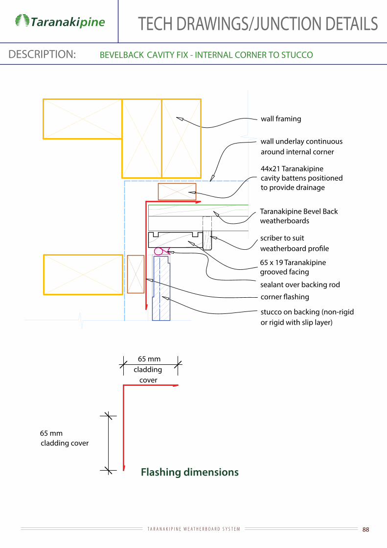
TECH DRAWINGS/JUNCTION DETAILSDESCRIPTION: BEVELBACK CAVITY FIX - INTERNAL CORNER TO STUCCO
Flashing dimensions
wall framing
wall underlay continuous around internal corner
Taranakipine Bevel Back weatherboards
65 mm
scriber to suit
65 x 19 Taranakipinegrooved facing
sealant over backing rod
stucco on backing (non-rigid or rigid with slip layer)
cladding cover
65 mmcladding
cover
44x21 Taranakipine cavity battens positioned to provide drainage

89T A R A N A K I P I N E W E A T H E R B O A R D S Y S T E M
TECH DRAWINGS/JUNCTION DETAILSDESCRIPTION: BEVELBACK
Flashing dimensions
CAVITY FIX - INTERNAL TO EIFS
wall framing
wall underlay continuous around internal corner
Taranakipine Bevel Back weatherboards
65 mm
65 mm
scriber to suit
65 x 19 Taranakipinegrooved facing
sealant over backing rod
EIFS cladding
cladding cover
cladding cover
44x21 Taranakipine cavity battens positioned to provide drainage

90T A R A N A K I P I N E W E A T H E R B O A R D S Y S T E M
TECH DRAWINGS/JUNCTION DETAILSDESCRIPTION: BEVELBACK
Flashing dimensions
CAVITY FIX - INTERNAL TO FIBRE CEMENT
wall framing
wall underlay continuous around internal corner
Taranakipine Bevel Back weatherboards
65 mm
scriber to suit
65 x 19 Taranakipinegrooved facing
cladding cover
65 mmcladding
cover
44x21 Taranakipine cavity battens positionedto provide drainage

91T A R A N A K I P I N E W E A T H E R B O A R D S Y S T E M
TECH DRAWINGS/JUNCTION DETAILSDESCRIPTION: BEVELBACK CAVITY FIX - INTERNAL TO MASONRY
wall framing
wall underlay continuous around internal corner
Taranakipine Bevel Back weatherboards
scriber to suit
masonry veneer cavity
masonry veneer
12 mm min
40 - 75 mm 30 mm
masonry veneer cavity
dimension to suit
3 mm gap to masonry
fold edge to
65 mmcladding
cover
44x21 Taranakipine cavity battens positionedto provide drainage

92T A R A N A K I P I N E W E A T H E R B O A R D S Y S T E M
TECH DRAWINGS/JUNCTION DETAILSDESCRIPTION: BEVELBACK CAVITY FIX - INTERNAL CORNER TO METAL
Flashing dimensions
Taranakipine Bevel Back weatherboard
wall framing
wall underlay continuous around internal corner
65 mm
scriber to suit
65 x 19 Taranakipinegrooved facing
cladding cover
cladding
turn up troughs at sheet ends sealant over backing rod
recommended)
min
20 mm
50 mm 25 mm
65 mmcladding
cover
44x21 Taranakipine cavity battens positionedto provide drainage

93T A R A N A K I P I N E W E A T H E R B O A R D S Y S T E M
TECH DRAWINGS/JUNCTION DETAILSDESCRIPTION: BEVELBACK CAVITY FIX - PARALLEL APRON FLASHING
Flashing dimensions
Taranakipine Bevel Back weatherboard
roof underlay carried up face of framing behind 70 mm min
35 mm min
cavity base closure positioned to give 10 mm drip edge to cladding and reversed so maximum area of opening required by E2/AS1 is not exceeded
75 mm min cover
overlap 2 crests minimum dimension, folded into next trough
turn down into trough35 mm min
on roof underlay and wire netting
removed without removal of cladding
44x21 Taranakipine cavity battens

94T A R A N A K I P I N E W E A T H E R B O A R D S Y S T E M
TECH DRAWINGS/JUNCTION DETAILSDESCRIPTION: BEVELBACK CAVITY FIX - ROOF/WALL JUNCTION AT GUTTER
in E2/AS1 for very high wind zones and all wind zones where roof pitch <10°
Taranakipine fascia board to suit gutter brackets and fall - 35 mm min fascia cover to weatherboard
gutter
Taranakipine Bevel Back weatherboards to NZS 3617
weatherboard lap
75
roof framing
behind weatherboards as shown in detail 1.2.6.4
on roof underlay and wire netting
internal lining
50 mm minoverhang taken from back face of
gutter
packer
44x21 Taranakipine cavity battens
95T A R A N A K I P I N E W E A T H E R B O A R D S Y S T E M
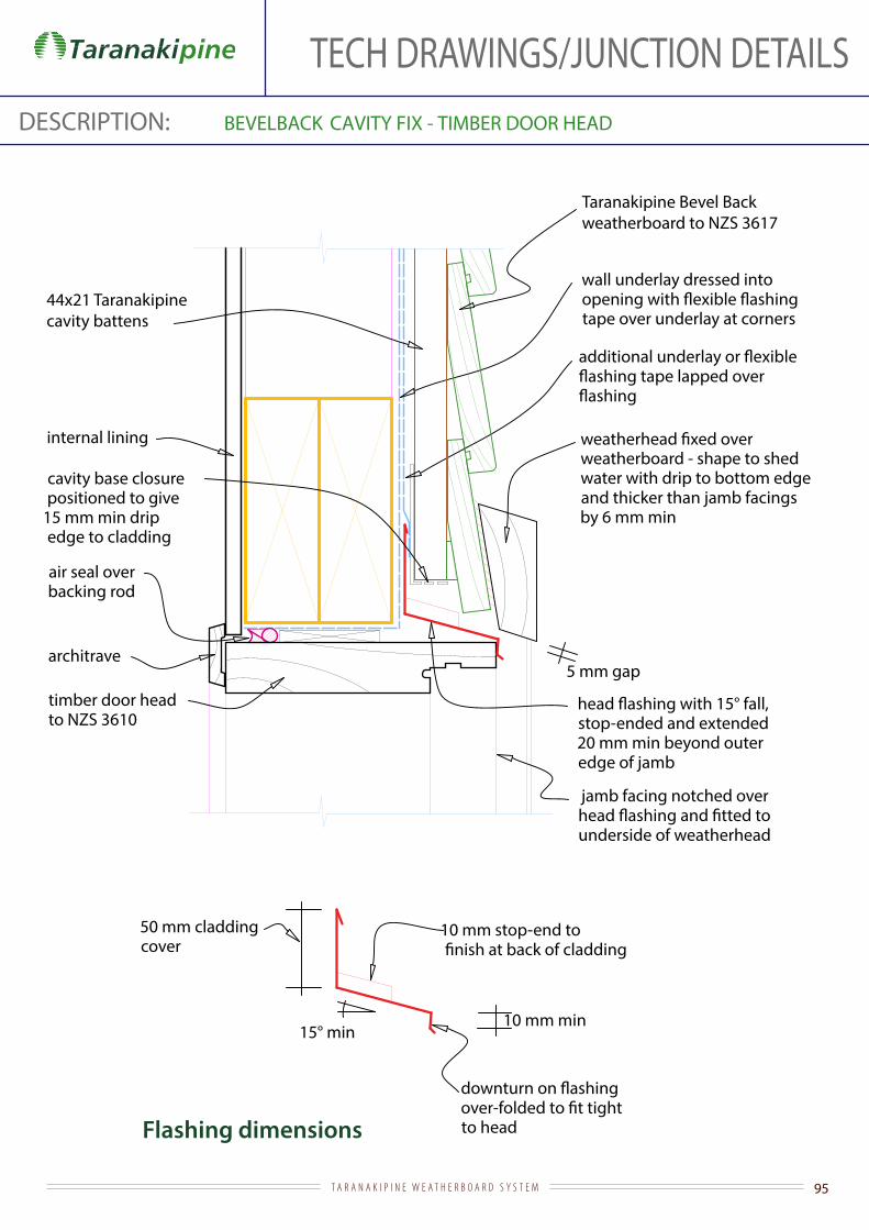
TECH DRAWINGS/JUNCTION DETAILSDESCRIPTION: BEVELBACK CAVITY FIX - TIMBER DOOR HEAD
Flashing dimensions
Taranakipine Bevel Back weatherboard to NZS 3617
stop-ended and extended 20 mm min beyond outer edge of jamb
internal lining
architrave
timber door head to NZS 3610
jamb facing notched over
underside of weatherhead
air seal over backing rod
wall underlay dressed into
tape over underlay at corners
weatherboard - shape to shed water with drip to bottom edge and thicker than jamb facings by 6 mm min
cavity base closure positioned to give
15 mm min drip edge to cladding
5 mm gap
15° min
to head
10 mm stop-end to
10 mm min
50 mm cladding cover
44x21 Taranakipine cavity battens

96T A R A N A K I P I N E W E A T H E R B O A R D S Y S T E M
TECH DRAWINGS/JUNCTION DETAILSDESCRIPTION: BEVELBACK CAVITY FIX - TIMBER DOOR JAMB
scriber
Taranakipine Bevel Back weatherboard to NZS 3617
timber door jamb to NZS 3610
architrave
internal lining
line of weatherhead over
extended to trimming studs
90 x 19 Taranakipinegrooved facing
19 mm min continuous jamb packing
air seal over backing rod
line of sill
wall underlay dressed
slotted into groove cut into underside of jamb
20 mm
44x21 Taranakipine cavity battens

97T A R A N A K I P I N E W E A T H E R B O A R D S Y S T E M
TECH DRAWINGS/JUNCTION DETAILSDESCRIPTION: BEVELBACK CAVITY FIX - TOP OF PARAPET
5° min slope
Taranakipine Bevel Back weatherboard to NZS 3617
wall underlay carried over top of framing
H3.1 min treated packer to provide fall
70 mm min70 mm min
additional underlay to provide separation of metal capping and copper-based treated timber
wall cladding
44x21 Taranakipine cavity battens

98T A R A N A K I P I N E W E A T H E R B O A R D S Y S T E M
TECH DRAWINGS/JUNCTION DETAILSDESCRIPTION: BEVELBACK CAVITY FIX - TOP OF SOLID HANDRAIL
5° min slope (10° recommended)
wall underlay carried over top of framing
H3.1 min treated packer to provide fall
70 mm min70 mm min
additional underlay to provide separation of metal capping and copper-based treated timber
10° min slope
wall underlay carried over top of framing
H3.2 treated capping shaped to provide falls
70 mm min 70 mm min
additional double layer underlay to provide separation between metal
treated timber positioned to secure
through top of capping
20 mm nominal cavity battens
H3.1 min treated wall framing
H3.1 min treated wall framing
behind main wall cladding at enclosed balustrade/wall junction
B1.2.9.2/3
C1.2.9.2/3
B1.2.9.2/3
C1.2.9.2/3
behind main wall cladding at enclosed balustrade/wall junction
B1.2.9.2/3 SECTION
B1.2.9.2/3SECTION (ALTERNATIVE)
Taranakipine Bevel Back weatherboard to NZS 3617
Taranakipine Bevel Back weatherboard to NZS 3617
44x21 Taranakipine cavity battens

99T A R A N A K I P I N E W E A T H E R B O A R D S Y S T E M
TECH DRAWINGS/JUNCTION DETAILSDESCRIPTION: BEVELBACK CAVITY FIX - TRANSVERSE APRON FLASHING
Flashing dimensions
Taranakipine Bevel Back weatherboard - to NZS 3617
underlay carried up face of framing behind 70 mm min
35 mm min
cavity base closure positioned to give 10 mm drip edge to cladding and reversed so maximum area of opening required by E2/AS1 is not exceeded
75 mm min cover
130 mm cover for L and M wind zones and >10° roof pitch; 200 mm cover for all other cases to max VH wind zone
edging into roof troughs
110 min200 mm
35 mm min
underlay and wire netting
Note: alternative top edge
shown to allow apron
without removal of cladding
44x21 Taranakipine cavity battens
100T A R A N A K I P I N E W E A T H E R B O A R D S Y S T E M
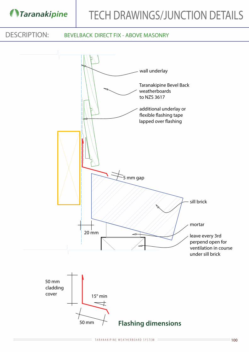
TECH DRAWINGS/JUNCTION DETAILSDESCRIPTION: BEVELBACK DIRECT FIX - ABOVE MASONRY
Flashing dimensions
leave every 3rd perpend open for ventilation in course under sill brick
50 mm cladding cover 15° min
sill brick
20 mm
50 mm
5 mm gap
mortar
wall underlay
Taranakipine Bevel Back weatherboards to NZS 3617
additional underlay or

101T A R A N A K I P I N E W E A T H E R B O A R D S Y S T E M
TECH DRAWINGS/JUNCTION DETAILSDESCRIPTION: BEVELBACK DIRECT FIX - ALUMINIUM SLIDING DOOR HEAD
Flashing dimensions
Taranakipine Bevel Back weatherboard
stop-ended and extended to edge of aluminium jamb facing
internal lining
35 mm facings
air seal over backing rod
additional underlay or
44x21 Taranakipine cavity battens
wall underlay dressed into
at corners
timber slimline reveal (or architrave)
cavity base closure positioned to give
15 mm min drip edge to cladding
weatherboard - shape to shed water with drip to bottom edge and project
15 mm past scriber
5 mm gap
against aluminium head facing
50 mm cladding cover
15° min
10 mm stop-end
10 mm min

102T A R A N A K I P I N E W E A T H E R B O A R D S Y S T E M
TECH DRAWINGS/JUNCTION DETAILSDESCRIPTION: BEVELBACK DIRECT FIX - ALUMINIUM SLIDING DOOR JAMB
Taranakipine Bevel Back weatherboard
internal lining
wall underlay dressed
line of weatherhead over
extending to trimming studs
19 mm min continuous jamb packing
air seal over backing rod
35 mm facingstimber slimline reveal (or architrave)
scriber extending to underside of weatherhead
15 mm
103T A R A N A K I P I N E W E A T H E R B O A R D S Y S T E M
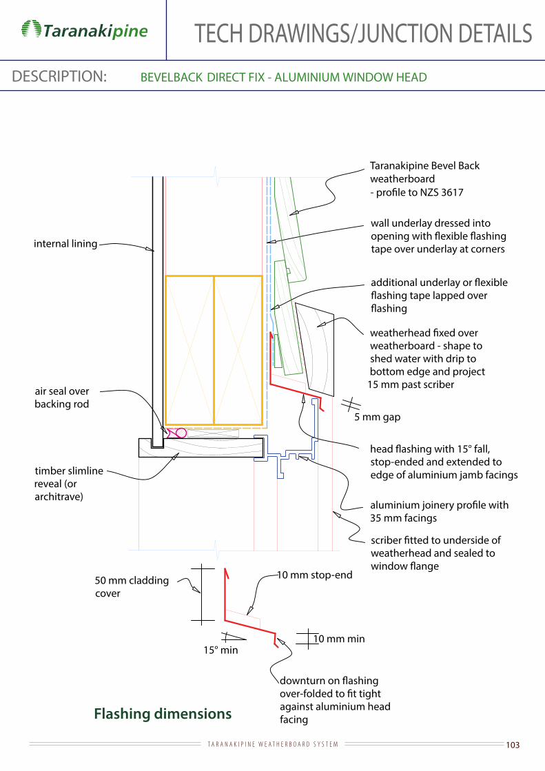
TECH DRAWINGS/JUNCTION DETAILSDESCRIPTION: BEVELBACK DIRECT FIX - ALUMINIUM WINDOW HEAD
Flashing dimensions
Taranakipine Bevel Back weatherboard
wall underlay dressed into
tape over underlay at corners
stop-ended and extended to edge of aluminium jamb facings
internal lining
timber slimline reveal (or architrave)
against aluminium head facing
35 mm facings
weatherboard - shape to shed water with drip to bottom edge and project
15 mm past scriber air seal over backing rod
weatherhead and sealed to
50 mm cladding cover
15° min
10 mm stop-end
10 mm min
5 mm gap

104T A R A N A K I P I N E W E A T H E R B O A R D S Y S T E M
TECH DRAWINGS/JUNCTION DETAILSDESCRIPTION: BEVELBACK DIRECT FIX - ALUMINIUM WINDOW JAMB
Taranakipine Bevel Back weatherboard
internal lining
wall underlay dressed
line of weatherhead over
extending to trimming studs
scriber extending to underside of weatherhead and 19 mm min continuous
jamb packer
air seal over backing rod
with 35 mm facings
timber slimline reveal (or architrave)
15 mm

105T A R A N A K I P I N E W E A T H E R B O A R D S Y S T E M
TECH DRAWINGS/JUNCTION DETAILSDESCRIPTION: BEVELBACK DIRECT FIX - ALUMINIUM WINDOW SILL
Flashing dimensions
wall underlay dressed into
sill turned up 100 mm at corners
Taranakipine Bevel Backweatherboards
air seal over backing rod
internal lining
chamfer sill framing as necessary to support sill
with 35 mm facings
to suit depth of aluminium
facings
5° fall min
line of scriber
full width sill tray
stop-ends
10 mm hem to back edge of
timber slimline reveal (or architrave)
line of continuous jamb packer
20 mm stop-end
width of opening
35 mm min
5 mm gap

106T A R A N A K I P I N E W E A T H E R B O A R D S Y S T E M
TECH DRAWINGS/JUNCTION DETAILSDESCRIPTION: BEVELBACK DIRECT FIX - BASE OF WALL (CONCRETE)
Taranakipine bevelback weatherboard -
ground level
internal lining
slab
foundation
50 mm
100 mm min (paved)175 mm min (unpaved )
wall underlaybottom plate on dpc
6 mm min
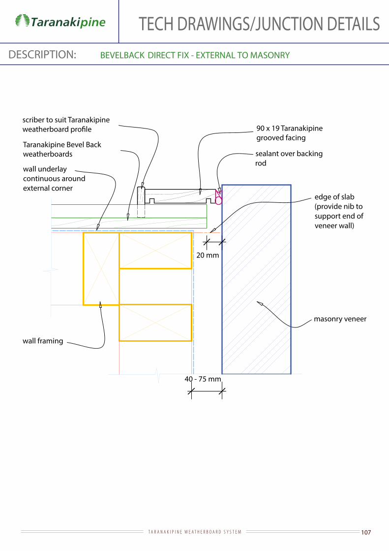
107T A R A N A K I P I N E W E A T H E R B O A R D S Y S T E M
TECH DRAWINGS/JUNCTION DETAILSDESCRIPTION: BEVELBACK DIRECT FIX - EXTERNAL TO MASONRY
wall framing
wall underlay continuous around external corner
Taranakipine Bevel Back weatherboards sealant over backing
rod
masonry veneer
scriber to suit Taranakipine
20 mm
40 - 75 mm
edge of slab (provide nib to support end of veneer wall)
90 x 19 Taranakipinegrooved facing
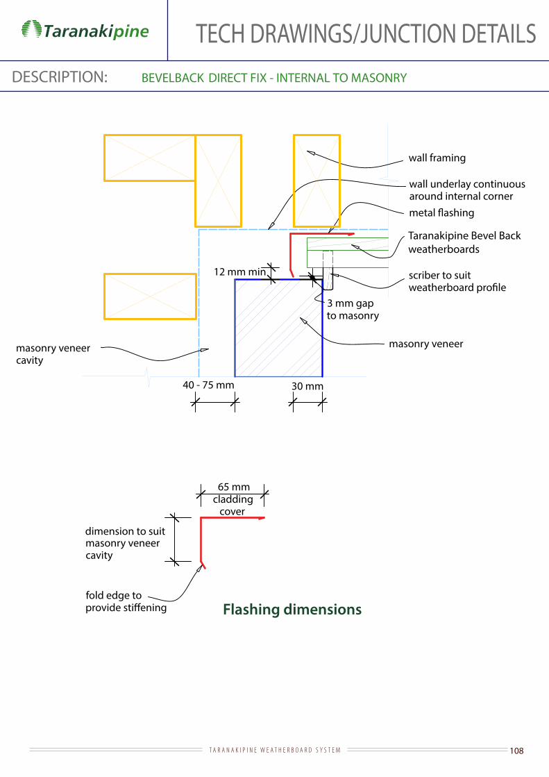
108T A R A N A K I P I N E W E A T H E R B O A R D S Y S T E M
TECH DRAWINGS/JUNCTION DETAILSDESCRIPTION: BEVELBACK DIRECT FIX - INTERNAL TO MASONRY
Flashing dimensions
Taranakipine Bevel Back weatherboards
wall framing
wall underlay continuous around internal corner
scriber to suit
masonry veneer cavity
masonry veneer
12 mm min
40 - 75 mm 30 mm
masonry veneer cavity
dimension to suit
fold edge to
3 mm gap to masonry
65 mmcladding
cover

109T A R A N A K I P I N E W E A T H E R B O A R D S Y S T E M
TECH DRAWINGS/JUNCTION DETAILSDESCRIPTION: BEVELBACK DIRECT FIX - TIMBER DOOR HEAD
Flashing dimensions
Taranakipine Bevel Back weatherboard to NZS 3617
wall underlay dressed into
at corners
stop-ended and extended 20 mm min beyond outer edge of jamb
internal lining
architrave
timber door head to NZS 3610
jamb facing notched over
underside of weatherhead
weatherboard - shape to shed water with drip to bottom edge and thicker than jamb facings by 6 mm min
air seal over backing rod
additional underlay or
50 mm cladding cover
15° min
to head
10 mm stop-end
5 mm gap
10 mm min
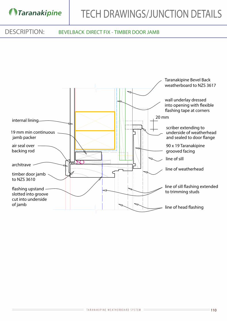
110T A R A N A K I P I N E W E A T H E R B O A R D S Y S T E M
TECH DRAWINGS/JUNCTION DETAILSDESCRIPTION: BEVELBACK DIRECT FIX - TIMBER DOOR JAMB
Taranakipine Bevel Back weatherboard to NZS 3617
timber door jamb to NZS 3610
architrave
internal lining
wall underlay dressed
line of weatherhead
to trimming studs
90 x 19 Taranakipine grooved facing
19 mm min continuous jamb packer
air seal over backing rod
line of sill
slotted into groove cut into underside of jamb
20 mm
scriber extending to underside of weatherhead
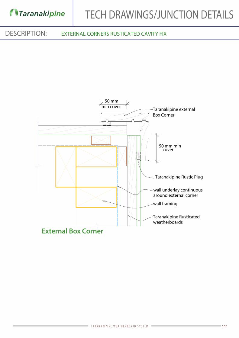
111T A R A N A K I P I N E W E A T H E R B O A R D S Y S T E M
DESCRIPTION: EXTERNAL CORNERS RUSTICATED CAVITY FIX
External Box Corner
wall framing
wall underlay continuousaround external corner
Taranakipine Rusticated weatherboards
Taranakipine externalBox Corner
50 mm min cover
Taranakipine Rustic Plug
50 mm mincover
TECH DRAWINGS/JUNCTION DETAILS
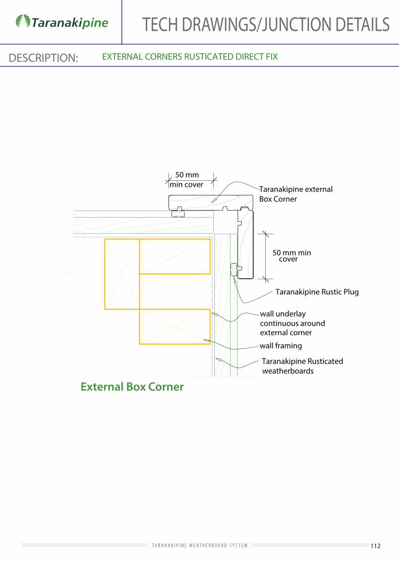
112T A R A N A K I P I N E W E A T H E R B O A R D S Y S T E M
DESCRIPTION: EXTERNAL CORNERS RUSTICATED DIRECT FIX
wall framing
wall underlaycontinuous around external corner
Taranakipine externalBox Corner
50 mm min cover
Taranakipine Rustic Plug
50 mm mincover
External Box Corner
Taranakipine Rusticated weatherboards
TECH DRAWINGS/JUNCTION DETAILS

113T A R A N A K I P I N E W E A T H E R B O A R D S Y S T E M
DESCRIPTION: RUSTICATED CAVITY FIX - INTERNAL CORNERS
65mm weatherboard cover
butt weatherboards into42x42 H3.1
wall underlay
Butted internal corner
Taranakipine internalBox Corner
Taranakipine Rustic Plug
Taranakipine Rusticatedweatherboards
65 mm overlap of
wall underlay
Internal Box Corner with Rustic Plug
TECH DRAWINGS/JUNCTION DETAILS
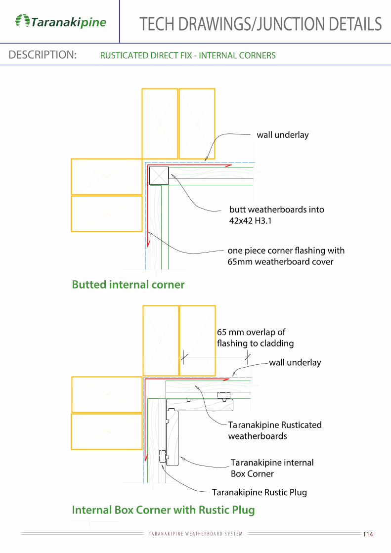
114T A R A N A K I P I N E W E A T H E R B O A R D S Y S T E M
DESCRIPTION: RUSTICATED DIRECT FIX - INTERNAL CORNERS
65mm weatherboard cover
butt weatherboards into42x42 H3.1
wall underlay
Butted internal corner
Internal Box Corner with Rustic Plug
Taranakipine internalBox Corner
Taranakipine Rustic Plug
Taranakipine Rusticatedweatherboards
65 mm overlap of
wall underlay
TECH DRAWINGS/JUNCTION DETAILS
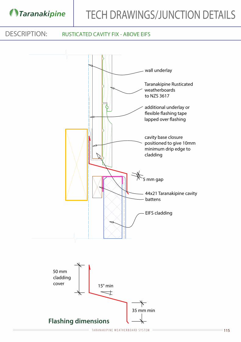
115T A R A N A K I P I N E W E A T H E R B O A R D S Y S T E M
TECH DRAWINGS/JUNCTION DETAILSDESCRIPTION: RUSTICATED CAVITY FIX - ABOVE EIFS
Flashing dimensions
cavity base closurepositioned to give 10mm minimum drip edge to cladding
44x21 Taranakipine cavity battens
EIFS cladding
wall underlay
Taranakipine Rusticated weatherboards to NZS 3617
additional underlay or
50 mm cladding cover
35 mm min
15° min
5 mm gap
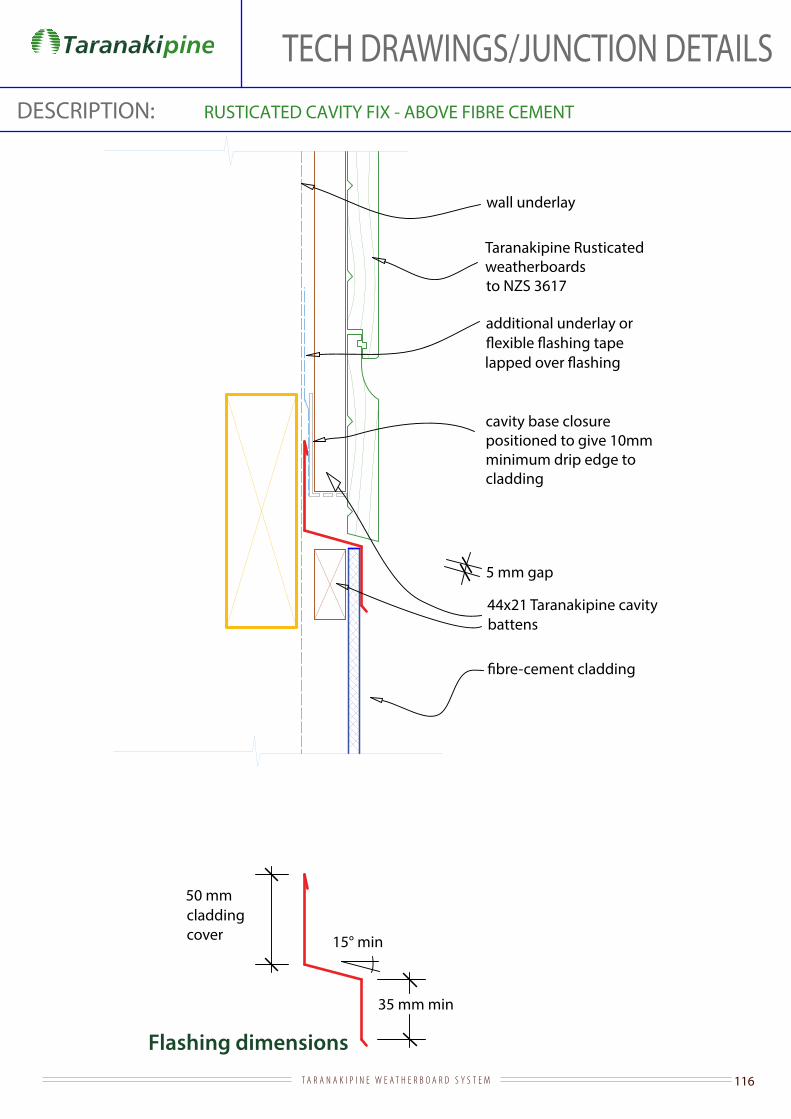
116T A R A N A K I P I N E W E A T H E R B O A R D S Y S T E M
TECH DRAWINGS/JUNCTION DETAILSDESCRIPTION: RUSTICATED CAVITY FIX - ABOVE FIBRE CEMENT
Flashing dimensions
50 mm cladding cover
35 mm min
15° min
cavity base closurepositioned to give 10mm minimum drip edge to cladding
44x21 Taranakipine cavity battens
wall underlay
Taranakipine Rusticated weatherboards to NZS 3617
additional underlay or
5 mm gap
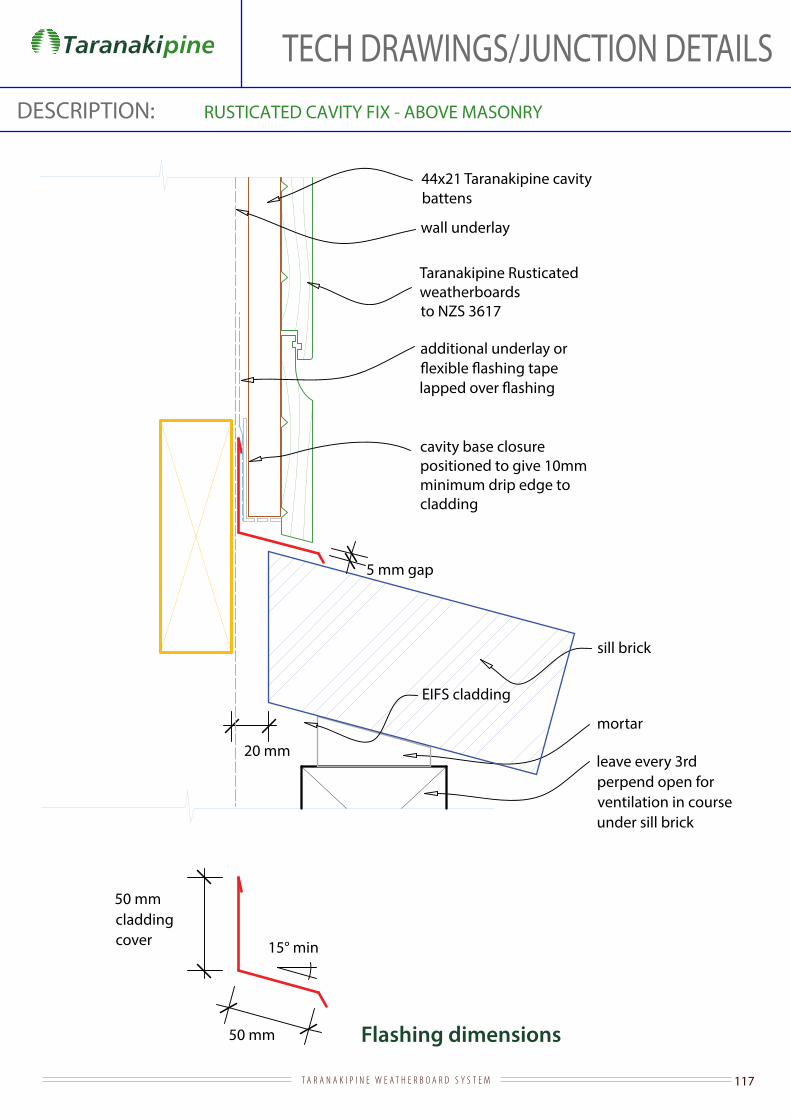
117T A R A N A K I P I N E W E A T H E R B O A R D S Y S T E M
TECH DRAWINGS/JUNCTION DETAILSDESCRIPTION: RUSTICATED CAVITY FIX - ABOVE MASONRY
Flashing dimensions
leave every 3rd perpend open for ventilation in course under sill brick
50 mm cladding cover 15° min
20 mm
50 mm
sill brick
mortar
cavity base closurepositioned to give 10mm minimum drip edge to cladding
44x21 Taranakipine cavity battens
EIFS cladding
wall underlay
Taranakipine Rusticatedweatherboards to NZS 3617
additional underlay or
5 mm gap
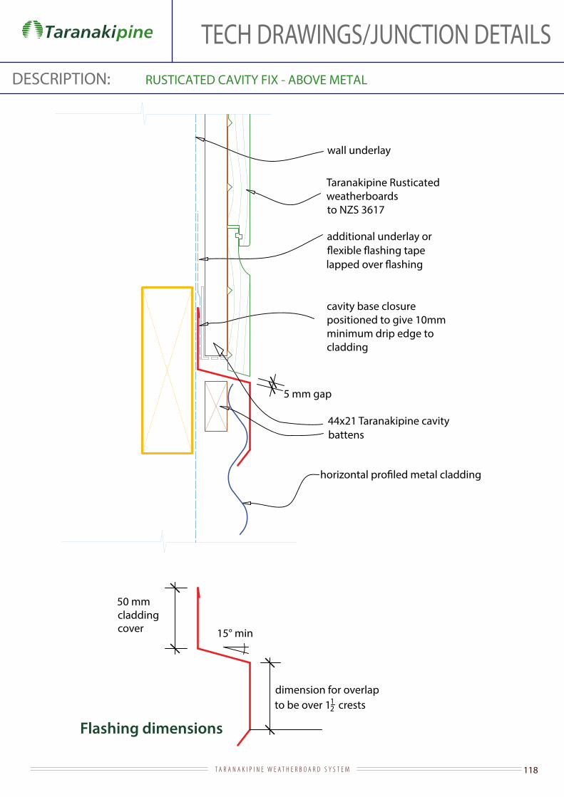
118T A R A N A K I P I N E W E A T H E R B O A R D S Y S T E M
TECH DRAWINGS/JUNCTION DETAILSDESCRIPTION: RUSTICATED CAVITY FIX - ABOVE METAL
Flashing dimensions
50 mm cladding cover 15° min
dimension for overlapto be over 11
2 crests
cavity base closurepositioned to give 10mm minimum drip edge to cladding
44x21 Taranakipine cavity battens
wall underlay
Taranakipine Rusticated weatherboards to NZS 3617
additional underlay or
5 mm gap
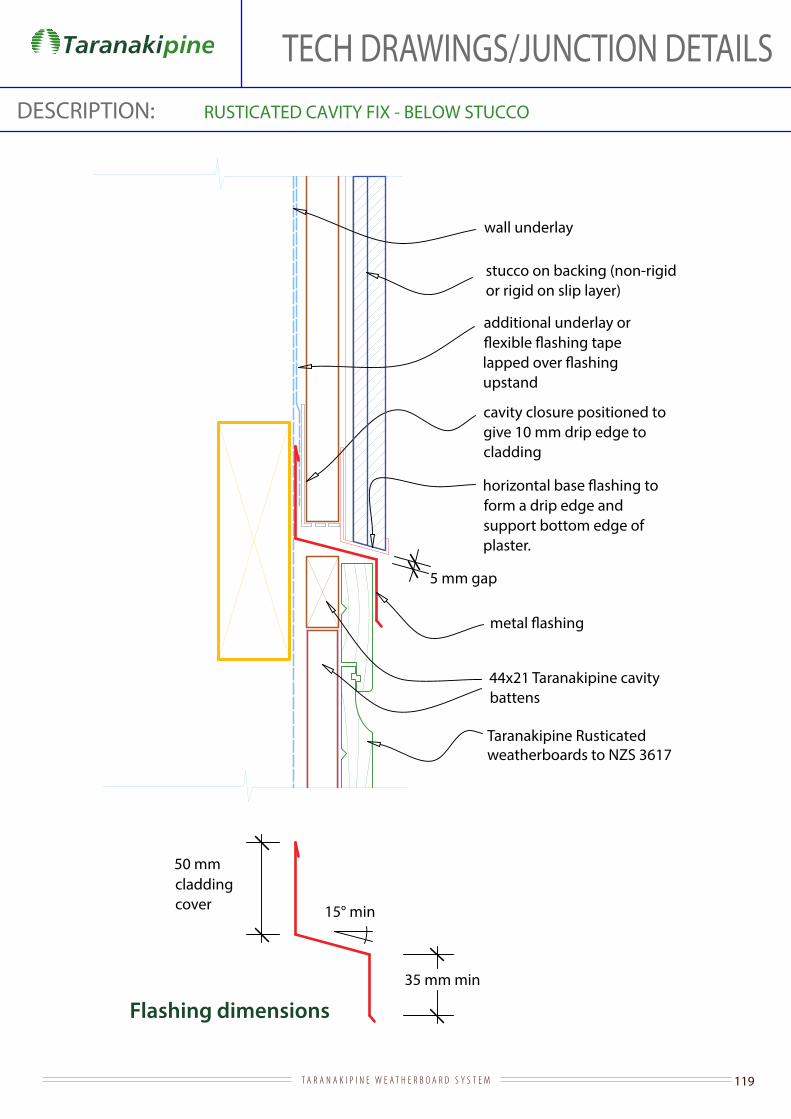
119T A R A N A K I P I N E W E A T H E R B O A R D S Y S T E M
TECH DRAWINGS/JUNCTION DETAILSDESCRIPTION: RUSTICATED CAVITY FIX - BELOW STUCCO
Flashing dimensions
form a drip edge and support bottom edge of plaster.
44x21 Taranakipine cavity battens
stucco on backing (non-rigid or rigid on slip layer)
wall underlay
Taranakipine Rusticated weatherboards to NZS 3617
additional underlay or
upstand
50 mm cladding cover
35 mm min
15° min
cavity closure positioned to give 10 mm drip edge to cladding
5 mm gap

120T A R A N A K I P I N E W E A T H E R B O A R D S Y S T E M
TECH DRAWINGS/JUNCTION DETAILSDESCRIPTION: RUSTICATED CAVITY FIX - ALUMINIUM SLIDING DOOR HEAD
Flashing dimensions
Taranakipine Rusticated weatherboard to NZS 3617
stop-ended and extended to edge of aluminium jamb facing
internal lining
35 mm facings
air seal over backing rod
additional underlay or
44x21 Taranakipine cavity battens
wall underlay dressed into
at corners
timber slimline reveal (or architrave)
cavity base closure positioned to give
15 mm min drip edge to cladding
weatherboard - shape to shed water with drip to bottom edge and project
15 mm past scriber
5 mm gap
against aluminium head facing
50 mm cladding cover
15° min
10 mm stop-end
10 mm min

121T A R A N A K I P I N E W E A T H E R B O A R D S Y S T E M
TECH DRAWINGS/JUNCTION DETAILSDESCRIPTION: RUSTICATED CAVITY FIX - ALUMINIUM SLIDING DOOR JAMB
Taranakipine Rusticated weatherboard
internal lining
line of weatherhead over
19 mm min continuous jamb packing
air seal over backing rod
with 35 mm facings
wall underlay dressed
44x21 Taranakipine cavity battens
timber slimline reveal (or architrave)
scriber extending to underside of weatherhead
15 mm
Taranakipine Rustic Plug

122T A R A N A K I P I N E W E A T H E R B O A R D S Y S T E M
TECH DRAWINGS/JUNCTION DETAILSDESCRIPTION: RUSTICATED CAVITY FIX - ALUMINIUM SLIDING DOOR SILL
cavity closure positioned to give 10 mm drip edge to cladding
Taranakipine Rusticatedweatherboards
air seal
timber packer
blocking to
boundary joists reduced in size
aluminium door sill with 35 mm facing
wall underlay dressed into
tape over full width of sill and turned up 100 mm at corners
44x21 Taranakipine cavity battens50
support bracket (as required by door manufacturer)
continuous jamb packer shown dotted
dpc
timber sill

123T A R A N A K I P I N E W E A T H E R B O A R D S Y S T E M
TECH DRAWINGS/JUNCTION DETAILSDESCRIPTION: RUSTICATED CAVITY FIX - ALUMINIUM WINDOW HEAD
Taranakipine Rusticated weatherboard
stop-ended and extended to edge of aluminium jamb facing
internal lining
35 mm facings
air seal over backing rod
44x21 Taranakipine cavity battens
wall underlay dressed into
at corners
timber slimline reveal (or architrave)
of weatherhead and sealed
cavity base closure positioned to give
15 mm min drip edge to cladding
weatherboard - shape to shed water with drip to bottom edge and project
15 mm past scriber
5 mm gap
15° min
to head
10 mm stop-end to
10 mm min
50 mm cladding cover
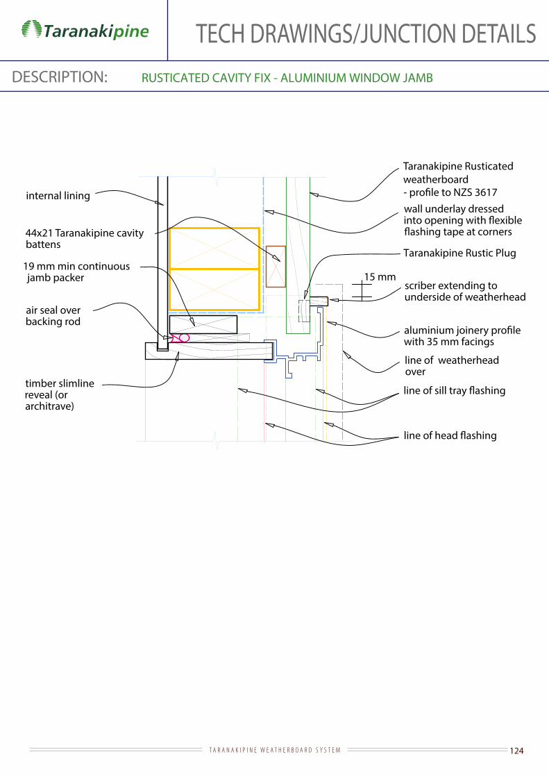
124T A R A N A K I P I N E W E A T H E R B O A R D S Y S T E M
TECH DRAWINGS/JUNCTION DETAILSDESCRIPTION: RUSTICATED CAVITY FIX - ALUMINIUM WINDOW JAMB
Taranakipine Rusticated weatherboard
internal lining
line of weatherhead over
19 mm min continuous jamb packer
air seal over backing rod
with 35 mm facings
wall underlay dressed
44x21 Taranakipine cavity battens
scriber extending to underside of weatherhead
timber slimline reveal (or architrave)
15 mm
Taranakipine Rustic Plug
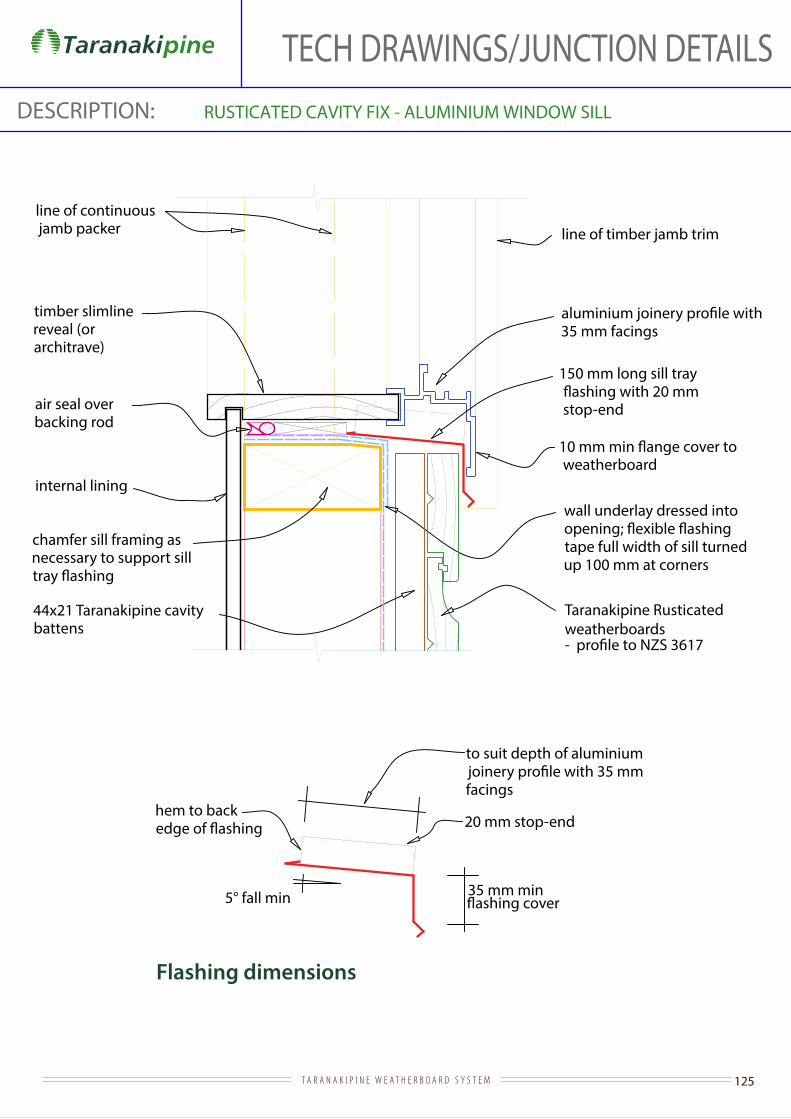
125T A R A N A K I P I N E W E A T H E R B O A R D S Y S T E M
TECH DRAWINGS/JUNCTION DETAILSDESCRIPTION: RUSTICATED CAVITY FIX - ALUMINIUM WINDOW SILL
Flashing dimensions
wall underlay dressed into
tape full width of sill turned up 100 mm at corners
Taranakipine Rusticated weatherboards
internal lining
44x21 Taranakipine cavity battens
line of continuous jamb packer
air seal over backing rod
chamfer sill framing as necessary to support sill
timber slimline reveal (or architrave)
5° fall min
20 mm stop-end hem to back
35 mm facings
line of timber jamb trim
150 mm long sill tray
stop-end
to suit depth of aluminium
facings
35 mm min
weatherboard

126T A R A N A K I P I N E W E A T H E R B O A R D S Y S T E M
TECH DRAWINGS/JUNCTION DETAILSDESCRIPTION: RUSTICATED CAVITY FIX - BASE OF WALL (CONCRETE)
ground level
internal lining
slab
foundation
50 mm
Taranakipine Rusticated
to NZS 3617
44x21 Taranakipine cavity battens
wall underlaybottom plate on dpc cavity base closure positioned to give
10 mm drip edge to cladding and reversed so maximum area of opening required by E2/AS1 is not exceeded
100 mm min (paved)175 mm min (unpaved )

127T A R A N A K I P I N E W E A T H E R B O A R D S Y S T E M
TECH DRAWINGS/JUNCTION DETAILSDESCRIPTION: RUSTICATED CAVITY FIX - BASE OF WALL (TIMBER)
Taranakipine Rusticated weatherboards to NZS 3617
boundary joists
wall underlay
44x21 Taranakipine cavity battens
50
cavity base closure positioned to give 10 mm drip edge to cladding and reversed so maximum area of opening required by E2/AS1 is not exceeded
wall plate on dpc
foundation wall

128T A R A N A K I P I N E W E A T H E R B O A R D S Y S T E M
TECH DRAWINGS/JUNCTION DETAILSDESCRIPTION: RUSTICATED CAVITY FIX - BELOW EIFS
Flashing dimensions
44x21 Taranakipine cavity battens
EIFS cladding
wall underlay
Taranakipine Rusticated weatherboards to NZS 3617
additional underlay or
lapped over bottom trim
50 mm cladding cover
35 mm min
15° min
proprietary PVC base trim
plaster to create drip edge
cavity closure positioned to give 10 mm drip edge to cladding
5 mm gap

129T A R A N A K I P I N E W E A T H E R B O A R D S Y S T E M
TECH DRAWINGS/JUNCTION DETAILSDESCRIPTION: RUSTICATED CAVITY FIX - BELOW FIBRE CEMENT
Flashing dimensions
44x21 Taranakipine cavity battens
wall underlay
Taranakipine Rusticated weatherboardsto NZS 3617
additional underlay or
50 mm cladding cover
35 mm min
15° min
cavity closure positioned to give 10 mm drip edge to cladding
5 mm gap

130T A R A N A K I P I N E W E A T H E R B O A R D S Y S T E M
TECH DRAWINGS/JUNCTION DETAILSDESCRIPTION: RUSTICATED CAVITY FIX - BELOW METAL
Flashing dimensions
44x21 Taranakipine cavity battens
wall underlay
Taranakipine Rusticated weatherboards to NZS 3617
bottom trim
100 mm minupstand
35 mm min
15° min
cavity closure reversed so maximum area of opening required by E2/AS1 is not exceeded, and positioned to give 10 mm drip edge to cladding
5 mm gap

131T A R A N A K I P I N E W E A T H E R B O A R D S Y S T E M
TECH DRAWINGS/JUNCTION DETAILSDESCRIPTION: RUSTICATED CAVITY FIX - BELOW STUCCO
Flashing dimensions
form a drip edge and support bottom edge of plaster.
44x21 Taranakipine cavity battens
stucco on backing (non-rigid or rigid on slip layer)
wall underlay
Taranakipine Rusticated weatherboards to NZS 3617
additional underlay or
upstand
50 mm cladding cover
35 mm min
15° min
cavity closure positioned to give 10 mm drip edge to cladding
5 mm gap

132T A R A N A K I P I N E W E A T H E R B O A R D S Y S T E M
TECH DRAWINGS/JUNCTION DETAILSDESCRIPTION: RUSTICATED CAVITY FIX - EXTERNAL CORNER TO METAL
Flashing dimensions
wall framing
wall underlay continuous around external corner
Taranakipine Rusticated weatherboards
115 x 19 and 90 x 19 Taranakipine grooved facing or alternatively Taranakipine external Box Corner
gap (10 mm recommended)
65 mm
100 mm cladding cover
cladding cover
Taranakipine Rustic Plug

133T A R A N A K I P I N E W E A T H E R B O A R D S Y S T E M
TECH DRAWINGS/JUNCTION DETAILSDESCRIPTION: RUSTICATED CAVITY FIX - EXTERNAL CORNER TO STUCCO
stucco on backing (non-rigid or rigid on slip layer)
wall framing
wall underlay continuous around external corner
Taranakipine Rusticatedweatherboards
115 x 19 and 90 x 19 Taranakipine grooved facing or alternatively Taranakipine external Box Corner
44x21 Taranakipine cavity battens at 400 crs
Taranakipine Rustic Plug

134T A R A N A K I P I N E W E A T H E R B O A R D S Y S T E M
TECH DRAWINGS/JUNCTION DETAILSDESCRIPTION: RUSTICATED CAVITY FIX - EXTERNAL TO EIFS
EIFS cladding
wall framing
wall underlay continuous around external corner
Taranakipine Rusticated weatherboards
115 x 19 and 90 x 19 Taranakipine grooved facing or alternatively Taranakipine external Box Corner
44x21 Taranakipine cavity battens
Taranakipine Rustic Plug

135T A R A N A K I P I N E W E A T H E R B O A R D S Y S T E M
TECH DRAWINGS/JUNCTION DETAILSDESCRIPTION: RUSTICATED CAVITY FIX - EXTERNAL TO FIBRE CEMENT
wall framing
wall underlay continuous around external corner
Taranakipine Rusticatedweatherboards
115 x 19 and 90 x 19 Taranakipine grooved facing or alternatively Taranakipine external Box Corner
44x21 Taranakipine cavity battens
Taranakipine Rustic Plug

136T A R A N A K I P I N E W E A T H E R B O A R D S Y S T E M
TECH DRAWINGS/JUNCTION DETAILSDESCRIPTION: RUSTICATED CAVITY FIX - EXTERNAL TO MASONRY
wall framing
wall underlay continuous around external corner
Taranakipine Rusticated weatherboards
sealant over backing rod
masonry veneer
20 mm
40 - 75 mm
edge of slab (provide nib to support end of veneer wall)
90 x 19 Taranakipine grooved facing
44 x 21 Taranakipine cavity battens
Taranakipine Rustic Plug

137T A R A N A K I P I N E W E A T H E R B O A R D S Y S T E M
TECH DRAWINGS/JUNCTION DETAILSDESCRIPTION: RUSTICATED CAVITY FIX - EXTERNAL CORNER TO METAL
Flashing dimensions
Taranakipine Rusticated weatherboard
wall framing
wall underlay continuous around external corner
65 mm
65 mm cladding cover
cladding cover
cladding
recommended)
min
20 mm
50 mm 25 mm
115 x 19 and 90 x 19 Taranakipine grooved facing or alternatively Taranakipine external Box Corner
44x21 Taranakipine cavity battens
Taranakipine Rustic Plug
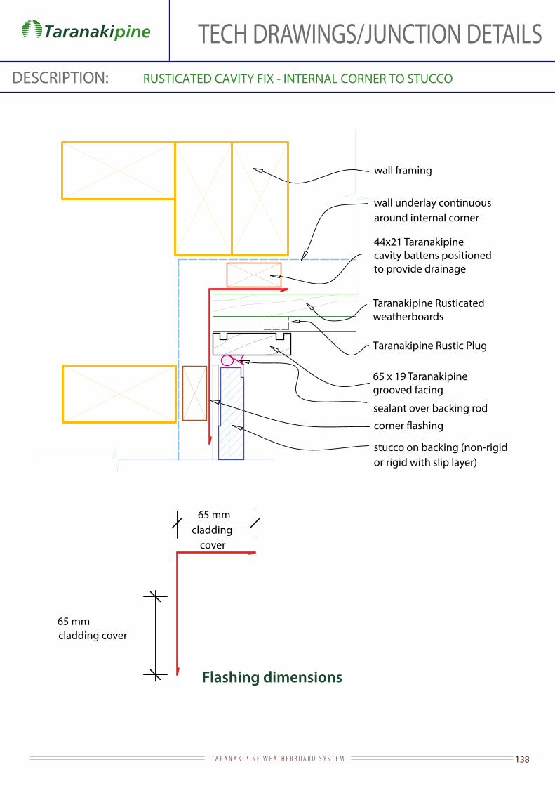
138T A R A N A K I P I N E W E A T H E R B O A R D S Y S T E M
TECH DRAWINGS/JUNCTION DETAILSDESCRIPTION: RUSTICATED CAVITY FIX - INTERNAL CORNER TO STUCCO
Flashing dimensions
wall framing
wall underlay continuous around internal corner
Taranakipine Rusticatedweatherboards
65 mm
65 x 19 Taranakipinegrooved facing
sealant over backing rod
stucco on backing (non-rigid or rigid with slip layer)
cladding cover
65 mmcladding
cover
44x21 Taranakipine cavity battens positioned to provide drainage
Taranakipine Rustic Plug
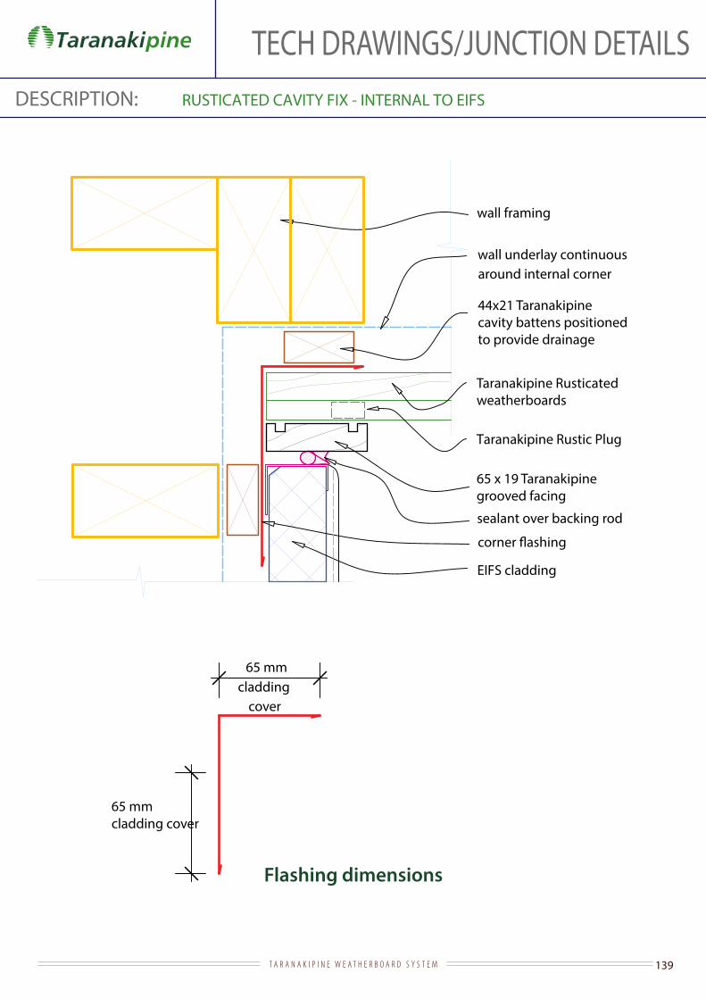
139T A R A N A K I P I N E W E A T H E R B O A R D S Y S T E M
TECH DRAWINGS/JUNCTION DETAILSDESCRIPTION: RUSTICATED CAVITY FIX - INTERNAL TO EIFS
Flashing dimensions
wall framing
wall underlay continuous around internal corner
Taranakipine Rusticated weatherboards
65 mm
65 mm
65 x 19 Taranakipinegrooved facing
sealant over backing rod
EIFS cladding
cladding cover
cladding cover
44x21 Taranakipine cavity battens positioned to provide drainage
Taranakipine Rustic Plug

140T A R A N A K I P I N E W E A T H E R B O A R D S Y S T E M
TECH DRAWINGS/JUNCTION DETAILSDESCRIPTION: RUSTICATED CAVITY FIX - INTERNAL TO FIBRE CEMENT
Flashing dimensions
wall framing
wall underlay continuous around internal corner
Taranakipine Bevel Back weatherboards
65 mm
65 x 19 Taranakipinegrooved facing
cladding cover
65 mmcladding
cover
44x21 Taranakipine cavity battens positionedto provide drainage
Taranakipine Rustic Plug
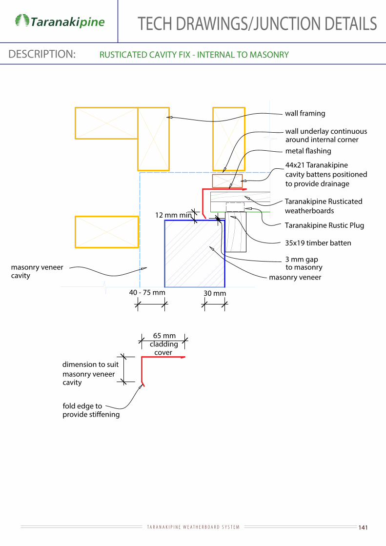
141T A R A N A K I P I N E W E A T H E R B O A R D S Y S T E M
TECH DRAWINGS/JUNCTION DETAILSDESCRIPTION: RUSTICATED CAVITY FIX - INTERNAL TO MASONRY
wall framing
wall underlay continuous around internal corner
Taranakipine Rusticated weatherboards
35x19 timber batten
masonry veneer cavity
masonry veneer
12 mm min
40 - 75 mm 30 mm
masonry veneer cavity
dimension to suit
3 mm gap to masonry
fold edge to
65 mmcladding
cover
44x21 Taranakipine cavity battens positionedto provide drainage
Taranakipine Rustic Plug
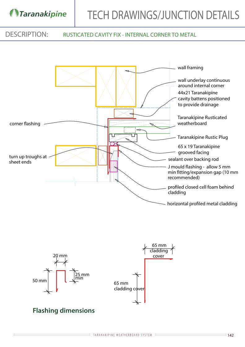
142T A R A N A K I P I N E W E A T H E R B O A R D S Y S T E M
TECH DRAWINGS/JUNCTION DETAILSDESCRIPTION: RUSTICATED CAVITY FIX - INTERNAL CORNER TO METAL
Flashing dimensions
Taranakipine Rusticatedweatherboard
wall framing
wall underlay continuous around internal corner
65 mm
65 x 19 Taranakipinegrooved facing
cladding cover
cladding
turn up troughs at sheet ends sealant over backing rod
recommended)
min
20 mm
50 mm 25 mm
65 mmcladding
cover
44x21 Taranakipine cavity battens positionedto provide drainage
Taranakipine Rustic Plug
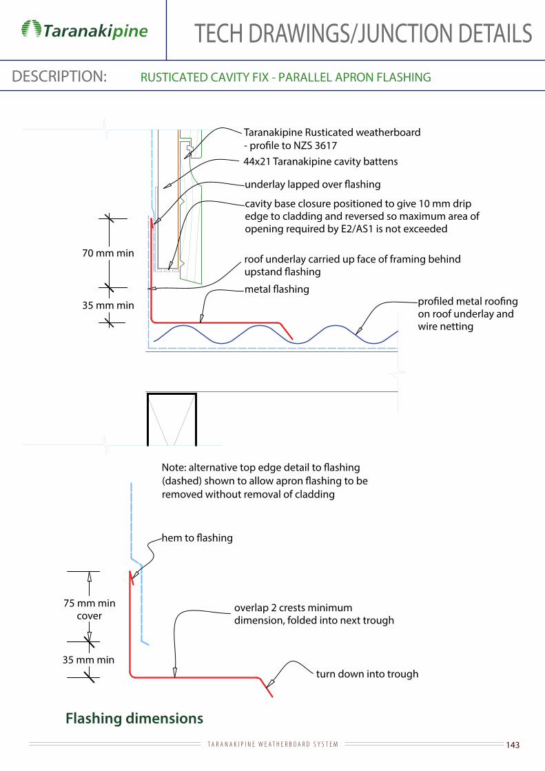
143T A R A N A K I P I N E W E A T H E R B O A R D S Y S T E M
TECH DRAWINGS/JUNCTION DETAILSDESCRIPTION: RUSTICATED CAVITY FIX - PARALLEL APRON FLASHING
Flashing dimensions
Taranakipine Rusticated weatherboard
roof underlay carried up face of framing behind 70 mm min
35 mm min
cavity base closure positioned to give 10 mm drip edge to cladding and reversed so maximum area of opening required by E2/AS1 is not exceeded
75 mm min cover
overlap 2 crests minimum dimension, folded into next trough
turn down into trough35 mm min
on roof underlay and wire netting
removed without removal of cladding
44x21 Taranakipine cavity battens

144T A R A N A K I P I N E W E A T H E R B O A R D S Y S T E M
TECH DRAWINGS/JUNCTION DETAILSDESCRIPTION: RUSTICATED CAVITY FIX - ROOF/WALL JUNCTION AT GUTTER
in E2/AS1 for very high wind zones and all wind zones where roof pitch <10°
Taranakipine fascia board to suit gutter brackets and fall - 35 mm min fascia cover to weatherboard
gutter
Taranakipine Rusticated weatherboards to NZS 3617
weatherboard lap
75
roof framing
behind weatherboards as shown in detail 1.2.6.4
on roof underlay and wire netting
internal lining
50 mm minoverhang taken from back face of
gutter
44x21 Taranakipine cavity battens

145T A R A N A K I P I N E W E A T H E R B O A R D S Y S T E M
TECH DRAWINGS/JUNCTION DETAILSDESCRIPTION: RUSTICATED CAVITY FIX - TIMBER DOOR HEAD
Flashing dimensions
Taranakipine Rusticated weatherboard to NZS 3617
stop-ended and extended 20 mm min beyond outer edge of jamb
internal lining
architrave
timber door head to NZS 3610
jamb facing notched over
underside of weatherhead
air seal over backing rod
wall underlay dressed into
tape over underlay at corners
weatherboard - shape to shed water with drip to bottom edge and thicker than jamb facings by 6 mm min
cavity base closure positioned to give
15 mm min drip edge to cladding
5 mm gap
15° min
to head
10 mm stop-end to
10 mm min
50 mm cladding cover
44x21 Taranakipine cavity battens

146T A R A N A K I P I N E W E A T H E R B O A R D S Y S T E M
TECH DRAWINGS/JUNCTION DETAILSDESCRIPTION: RUSTICATED DIRECT FIX - TIMBER DOOR JAMB
Taranakipine Rustic Plug
Taranakipine Rusticated weatherboard to NZS 3617
timber door jamb to NZS 3610
architrave
internal lining
wall underlay dressed
line of weatherhead
to trimming studs
90 x 19 Taranakipine grooved facing
19 mm min continuous jamb packer
air seal over backing rod
line of sill
slotted into groove cut into underside of jamb
20 mm
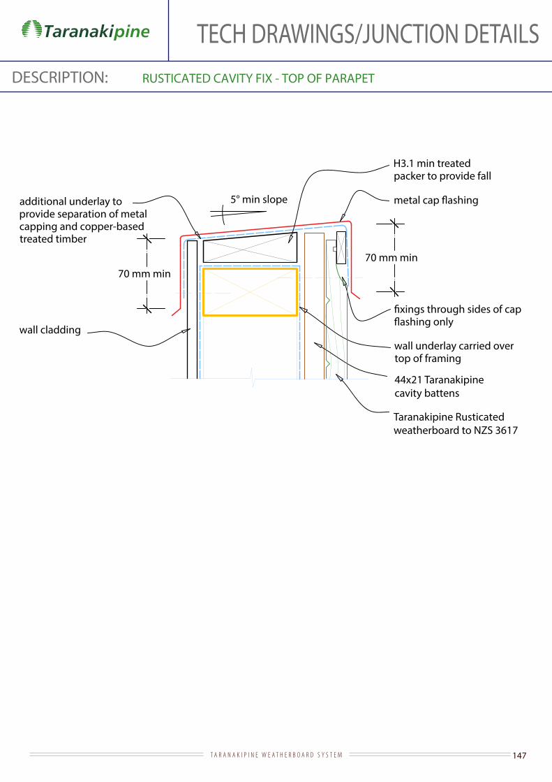
147T A R A N A K I P I N E W E A T H E R B O A R D S Y S T E M
TECH DRAWINGS/JUNCTION DETAILSDESCRIPTION: RUSTICATED CAVITY FIX - TOP OF PARAPET
5° min slope
Taranakipine Rusticated weatherboard to NZS 3617
wall underlay carried over top of framing
H3.1 min treated packer to provide fall
70 mm min70 mm min
additional underlay to provide separation of metal capping and copper-based treated timber
wall cladding
44x21 Taranakipine cavity battens

148T A R A N A K I P I N E W E A T H E R B O A R D S Y S T E M
TECH DRAWINGS/JUNCTION DETAILSDESCRIPTION: RUSTICATED CAVITY FIX - TOP OF SOLID HANDRAIL
5° min slope (10° recommended)
wall underlay carried over top of framing
H3.1 min treated packer to provide fall
70 mm min70 mm min
additional underlay to provide separation of metal capping and copper-based treated timber
10° min slope
wall underlay carried over top of framing
H3.2 treated capping shaped to provide falls
70 mm min 70 mm min
additional double layer underlay to provide separation between metal
treated timber positioned to secure
through top of capping
20 mm nominal cavity battens
H3.1 min treated wall framing
H3.1 min treated wall framing
behind main wall cladding at enclosed balustrade/wall junction
B1.2.9.2/3
C1.2.9.2/3
B1.2.9.2/3
C1.2.9.2/3
behind main wall cladding at enclosed balustrade/wall junction
B1.2.9.2/3 SECTION
B1.2.9.2/3SECTION (ALTERNATIVE)
Taranakipine Rusticated weatherboard to NZS 3617
Taranakipine Rusticated weatherboard to NZS 3617
44x21 Taranakipine cavity battens

149T A R A N A K I P I N E W E A T H E R B O A R D S Y S T E M
TECH DRAWINGS/JUNCTION DETAILSDESCRIPTION: RUSTICATED CAVITY FIX - TRANSVERSE APRON FLASHING
Flashing dimensions
Taranakipine Rusticated weatherboard - to NZS 3617
underlay carried up face of framing behind 70 mm min
35 mm min
cavity base closure positioned to give 10 mm drip edge to cladding and reversed so maximum area of opening required by E2/AS1 is not exceeded
75 mm min cover
130 mm cover for L and M wind zones and >10° roof pitch; 200 mm cover for all other cases to max VH wind zone
edging into roof troughs
110 min200 mm
35 mm min
underlay and wire netting
Note: alternative top edge
shown to allow apron
without removal of cladding
44x21 Taranakipine cavity battens

150T A R A N A K I P I N E W E A T H E R B O A R D S Y S T E M
TECH DRAWINGS/JUNCTION DETAILSDESCRIPTION: RUSTICATED DIRECT FIX - ABOVE MASONRY
Flashing dimensions
leave every 3rd perpend open for ventilation in course under sill brick
50 mm cladding cover 15° min
sill brick
20 mm
50 mm
5 mm gap
mortar
wall underlay
Taranakipine Rusticated weatherboards to NZS 3617
additional underlay or

151T A R A N A K I P I N E W E A T H E R B O A R D S Y S T E M
TECH DRAWINGS/JUNCTION DETAILSDESCRIPTION: RUSTICATED DIRECT FIX - ALUMINIUM SLIDING DOOR HEAD
Flashing dimensions
Taranakipine Rusticatedweatherboard
stop-ended and extended to edge of aluminium jamb facing
internal lining
35 mm facings
air seal over backing rod
additional underlay or
wall underlay dressed into
at corners
timber slimline reveal (or architrave)
cavity base closure positioned to give
15 mm min drip edge to cladding
weatherboard - shape to shed water with drip to bottom edge and project
15 mm past scriber
5 mm gap
against aluminium head facing
50 mm cladding cover
15° min
10 mm stop-end
10 mm min
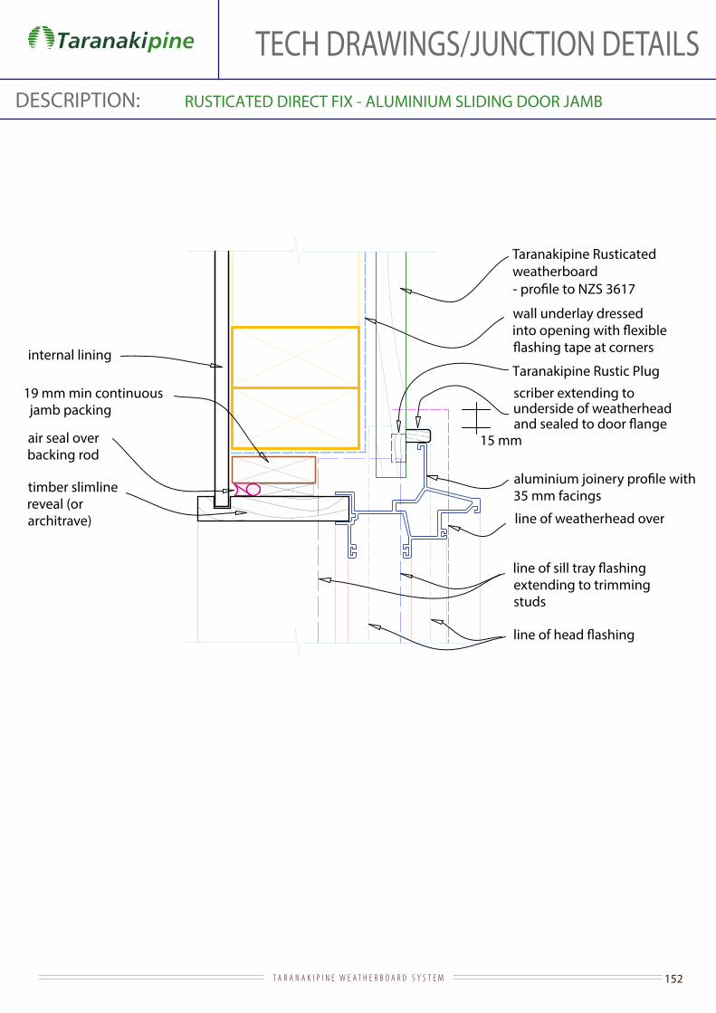
152T A R A N A K I P I N E W E A T H E R B O A R D S Y S T E M
TECH DRAWINGS/JUNCTION DETAILSDESCRIPTION: RUSTICATED DIRECT FIX - ALUMINIUM SLIDING DOOR JAMB
Taranakipine Rusticated weatherboard
internal lining
wall underlay dressed
line of weatherhead over
extending to trimming studs
19 mm min continuous jamb packing
air seal over backing rod
35 mm facingstimber slimline reveal (or architrave)
15 mm
scriber extending to underside of weatherhead
Taranakipine Rustic Plug

153T A R A N A K I P I N E W E A T H E R B O A R D S Y S T E M
TECH DRAWINGS/JUNCTION DETAILSDESCRIPTION: RUSTICATED DIRECT FIX - ALUMINIUM WINDOW HEAD
Flashing dimensions
Taranakipine Rusticated weatherboard
wall underlay dressed into
tape over underlay at corners
stop-ended and extended to edge of aluminium jamb facings
internal lining
timber slimline reveal (or architrave)
against aluminium head facing
35 mm facings
weatherboard - shape to shed water with drip to bottom edge and project
15 mm past scriber air seal over backing rod
weatherhead and sealed to
50 mm cladding cover
15° min
10 mm stop-end
10 mm min
5 mm gap

154T A R A N A K I P I N E W E A T H E R B O A R D S Y S T E M
TECH DRAWINGS/JUNCTION DETAILSDESCRIPTION: RUSTICATED DIRECT FIX - ALUMINIUM WINDOW JAMB
Taranakipine Rusticated weatherboard
internal lining
wall underlay dressed
line of weatherhead over
extending to trimming studs
scriber extending to underside of weatherhead and
19 mm min continuous jamb packer
air seal over backing rod
with 35 mm facings
timber slimline reveal (or architrave)
15 mm

155T A R A N A K I P I N E W E A T H E R B O A R D S Y S T E M
TECH DRAWINGS/JUNCTION DETAILSDESCRIPTION: RUSTICATED DIRECT FIX - ALUMINIUM WINDOW SILL
Flashing dimensions
wall underlay dressed into
sill turned up 100 mm at corners
Taranakipine Rusticatedweatherboards
air seal over backing rod
internal lining
chamfer sill framing as necessary to support sill
with 35 mm facings
to suit depth of aluminium
facings
5° fall min
line of scriber
full width sill tray
stop-ends
10 mm hem to back edge of
timber slimline reveal (or architrave)
line of continuous jamb packer
20 mm stop-end
width of opening
35 mm min
5 mm gap

156T A R A N A K I P I N E W E A T H E R B O A R D S Y S T E M
TECH DRAWINGS/JUNCTION DETAILSDESCRIPTION: RUSTICATED DIRECT FIX - BASE OF WALL (CONCRETE)
Taranakipine Rusticated weatherboard -
ground level
internal lining
slab
foundation
50 mm
100 mm min (paved)175 mm min (unpaved )
wall underlaybottom plate on dpc
6 mm min
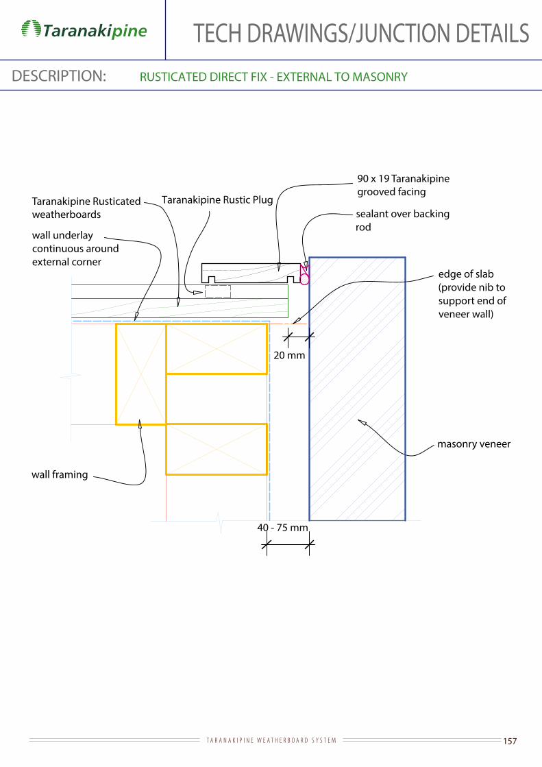
157T A R A N A K I P I N E W E A T H E R B O A R D S Y S T E M
TECH DRAWINGS/JUNCTION DETAILSDESCRIPTION: RUSTICATED DIRECT FIX - EXTERNAL TO MASONRY
wall framing
wall underlay continuous around external corner
Taranakipine Rusticated weatherboards sealant over backing
rod
masonry veneer
20 mm
40 - 75 mm
edge of slab (provide nib to support end of veneer wall)
90 x 19 Taranakipinegrooved facing
Taranakipine Rustic Plug

158T A R A N A K I P I N E W E A T H E R B O A R D S Y S T E M
TECH DRAWINGS/JUNCTION DETAILSDESCRIPTION: RUSTICATED DIRECT FIX - INTERNAL TO MASONRY
Flashing dimensions
Taranakipine Rusticated weatherboards
wall framing
wall underlay continuous around internal corner
Taranakipine Rustic Plug
masonry veneer cavity
masonry veneer
12 mm min
40 - 75 mm 30 mm
masonry veneer cavity
dimension to suit
fold edge to
65 mmcladding
cover
3 mm gap to masonry
35x19 timber batten
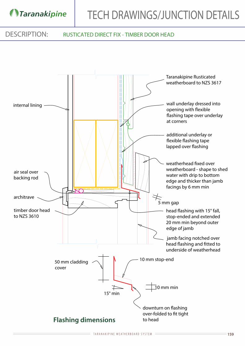
159T A R A N A K I P I N E W E A T H E R B O A R D S Y S T E M
TECH DRAWINGS/JUNCTION DETAILSDESCRIPTION: RUSTICATED DIRECT FIX - TIMBER DOOR HEAD
Flashing dimensions
Taranakipine Rusticated weatherboard to NZS 3617
wall underlay dressed into
at corners
stop-ended and extended 20 mm min beyond outer edge of jamb
internal lining
architrave
timber door head to NZS 3610
jamb facing notched over
underside of weatherhead
weatherboard - shape to shed water with drip to bottom edge and thicker than jamb facings by 6 mm min
air seal over backing rod
additional underlay or
50 mm cladding cover
15° min
to head
10 mm stop-end
5 mm gap
10 mm min

160T A R A N A K I P I N E W E A T H E R B O A R D S Y S T E M
TECH DRAWINGS/JUNCTION DETAILSDESCRIPTION: RUSTICATED CAVITY FIX - TIMBER DOOR JAMB
Taranakipine Rusticated weatherboard to NZS 3617
timber door jamb to NZS 3610
architrave
internal lining
line of weatherhead over
extended to trimming studs
90 x 19 Taranakipinegrooved facing
19 mm min continuous jamb packing
air seal over backing rod
line of sill
wall underlay dressed
slotted into groove cut into underside of jamb
20 mm44x21 Taranakipine cavity battens
Taranakipine Rustic Plug

161T A R A N A K I P I N E W E A T H E R B O A R D S Y S T E M
DESCRIPTION: EXTERNAL CORNERS VERTICAL SHIPLAP CAVITY FIX
External Box Corner
wall framing
wall underlay continuousaround external corner
Taranakipine Vertical Shiplapweatherboards
Taranakipine externalBox Corner
50 mm min cover
50 mm mincover
Cavibat or castellated timber cavity batten
TECH DRAWINGS/JUNCTION DETAILS

162T A R A N A K I P I N E W E A T H E R B O A R D S Y S T E M
DESCRIPTION: EXTERNAL CORNERS VERTICAL SHIPLAP DIRECT FIX
wall framing
wall underlaycontinuous around external corner
Taranakipine externalBox Corner
50 mm min cover
50 mm mincover
External Box Corner
Taranakipine Vertical Shiplapweatherboards
TECH DRAWINGS/JUNCTION DETAILS

163T A R A N A K I P I N E W E A T H E R B O A R D S Y S T E M
DESCRIPTION: VERTICAL SHIPLAP CAVITY FIX - INTERNAL CORNERS
65mm weatherboard cover
wall underlay
Butted internal corner
Taranakipine internalBox Corner
Taranakipine Vertical Shiplap weatherboards
65 mm overlap of
wall underlay
Internal Box Corner
Taranakipine VerticalShiplap weatherboards
Cavibat or castellated timber cavity batten
Cavibat or castellated timber cavity batten
TECH DRAWINGS/JUNCTION DETAILS

164T A R A N A K I P I N E W E A T H E R B O A R D S Y S T E M
DESCRIPTION: VERTICAL SHIPLAP DIRECT FIX - INTERNAL CORNERS
65mm weatherboard cover
wall underlay
Butted internal corner
Internal Box Corner
Taranakipine internalBox Corner
Taranakipine Vertical Shiplapweatherboards
65 mm overlap of
wall underlay
Taranakipine VerticalShiplap weatherboards
TECH DRAWINGS/JUNCTION DETAILS
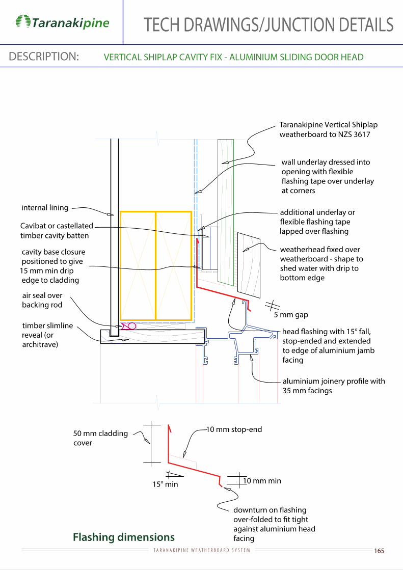
165T A R A N A K I P I N E W E A T H E R B O A R D S Y S T E M
TECH DRAWINGS/JUNCTION DETAILSDESCRIPTION: VERTICAL SHIPLAP CAVITY FIX - ALUMINIUM SLIDING DOOR HEAD
Flashing dimensions
Taranakipine Vertical Shiplap weatherboard to NZS 3617
stop-ended and extended to edge of aluminium jamb facing
internal lining
35 mm facings
air seal over backing rod
additional underlay or
wall underlay dressed into
at corners
timber slimline reveal (or architrave)
cavity base closure positioned to give
15 mm min drip edge to cladding
weatherboard - shape to shed water with drip to bottom edge
5 mm gap
against aluminium head facing
50 mm cladding cover
15° min
10 mm stop-end
10 mm min
Cavibat or castellatedtimber cavity batten
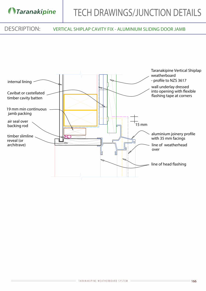
166T A R A N A K I P I N E W E A T H E R B O A R D S Y S T E M
TECH DRAWINGS/JUNCTION DETAILSDESCRIPTION: VERTICAL SHIPLAP CAVITY FIX - ALUMINIUM SLIDING DOOR JAMB
Taranakipine Vertical Shiplap weatherboard
internal lining
line of weatherhead over
19 mm min continuous jamb packing
air seal over backing rod
with 35 mm facings
wall underlay dressed
timber slimline reveal (or architrave)
15 mm
Cavibat or castellatedtimber cavity batten

167T A R A N A K I P I N E W E A T H E R B O A R D S Y S T E M
TECH DRAWINGS/JUNCTION DETAILSDESCRIPTION: VERTICAL SHIPLAP CAVITY FIX - ALUMINIUM SLIDING DOOR SILL
cavity closure positioned to give 10 mm drip edge to cladding
Taranakipine Vertical Shiplapweatherboards
air seal
timber packer
blocking to
boundary joists reduced in size
aluminium door sill with 35 mm facing
wall underlay dressed into
tape over full width of sill and turned up 100 mm at corners
50
support bracket (as required by door manufacturer)
continuous jamb packer shown dotted
dpc
timber sill
Cavibat or castellatedtimber cavity batten
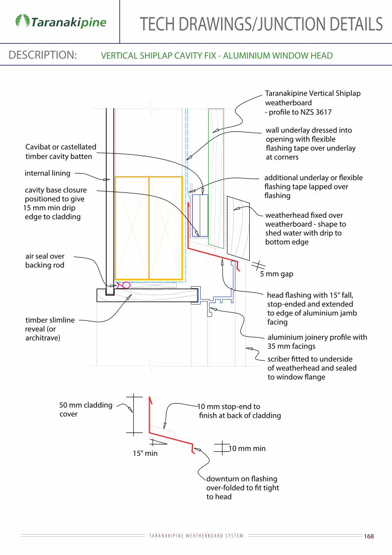
168T A R A N A K I P I N E W E A T H E R B O A R D S Y S T E M
TECH DRAWINGS/JUNCTION DETAILSDESCRIPTION: VERTICAL SHIPLAP CAVITY FIX - ALUMINIUM WINDOW HEAD
Taranakipine Vertical Shiplap weatherboard
stop-ended and extended to edge of aluminium jamb facing
internal lining
35 mm facings
air seal over backing rod
wall underlay dressed into
at corners
timber slimline reveal (or architrave)
of weatherhead and sealed
cavity base closure positioned to give
15 mm min drip edge to cladding
weatherboard - shape to shed water with drip to bottom edge
5 mm gap
15° min
to head
10 mm stop-end to
10 mm min
50 mm cladding cover
Cavibat or castellatedtimber cavity batten

169T A R A N A K I P I N E W E A T H E R B O A R D S Y S T E M
TECH DRAWINGS/JUNCTION DETAILSDESCRIPTION: VERTICAL SHIPLAP CAVITY FIX - ALUMINIUM WINDOW JAMB
Taranakipine Vertical Shiplap weatherboard
internal lining
line of weatherhead over
19 mm min continuous jamb packer
air seal over backing rod
with 35 mm facings
wall underlay dressed
timber slimline reveal (or architrave)
Cavibat or castellatedtimber cavity batten
15 mm

170T A R A N A K I P I N E W E A T H E R B O A R D S Y S T E M
TECH DRAWINGS/JUNCTION DETAILSDESCRIPTION: VERTICAL SHIPLAP CAVITY FIX - ALUMINIUM WINDOW SILL
Flashing dimensions
wall underlay dressed into
tape full width of sill turned up 100 mm at corners
Taranakipine Vertical Shiplap weatherboards
internal lining
line of continuous jamb packer
air seal over backing rod
chamfer sill framing as necessary to support sill
timber slimline reveal (or architrave)
5° fall min
20 mm stop-end hem to back
35 mm facings
line of timber jamb trim
150 mm long sill tray
stop-end
to suit depth of aluminium
facings
35 mm min
weatherboard
Cavibat or castellatedtimber cavity batten

171T A R A N A K I P I N E W E A T H E R B O A R D S Y S T E M
TECH DRAWINGS/JUNCTION DETAILSDESCRIPTION: VERTICAL SHIPLAP CAVITY FIX - BASE OF WALL (CONCRETE)
ground level
internal lining
slab
foundation
50 mm
Taranakipine Vertical Shiplap
to NZS 3617
wall underlaybottom plate on dpc
cavity base closure positioned to give 10 mm drip edge to cladding and reversed so maximum area of opening required by E2/AS1 is not exceeded
100 mm min (paved)175 mm min (unpaved )
Cavibat or castellatedtimber cavity batten

172T A R A N A K I P I N E W E A T H E R B O A R D S Y S T E M
TECH DRAWINGS/JUNCTION DETAILSDESCRIPTION: VERTICAL SHIPLAP CAVITY FIX - BASE OF WALL (TIMBER)
Taranakipine Vertical Shiplapweatherboards to NZS 3617
boundary joists
wall underlay
50
cavity base closure positioned to give 10 mm drip edge to cladding and reversed so maximum area of opening required by E2/AS1 is not exceeded
wall plate on dpc
foundation wall
Cavibat or castellatedtimber cavity batten

173T A R A N A K I P I N E W E A T H E R B O A R D S Y S T E M
TECH DRAWINGS/JUNCTION DETAILSDESCRIPTION: VERTICAL SHIPLAP CAVITY FIX - ROOF/WALL JUNCTION AT GUTTER
in E2/AS1 for very high wind zones and all wind zones where roof pitch <10°
Taranakipine fascia board to suit gutter brackets and fall - 35 mm min fascia cover to weatherboard
gutter
Taranakipine Vertical Shiplapweatherboards to NZS 3617
weatherboard lap
75
roof framing
behind weatherboards as shown in detail 1.2.6.4
on roof underlay and wire netting
internal lining
50 mm minoverhang taken from back face of
gutter
Cavibat or castellatedtimber cavity batten

174T A R A N A K I P I N E W E A T H E R B O A R D S Y S T E M
TECH DRAWINGS/JUNCTION DETAILSDESCRIPTION: VERTICAL SHIPLAP CAVITY FIX - TIMBER DOOR HEAD
Flashing dimensions
Taranakipine Vertical Shiplap weatherboard to NZS 3617
stop-ended and extended 20 mm min beyond outer edge of jamb
internal lining
architrave
timber door head to NZS 3610
jamb facing notched over
underside of weatherhead
air seal over backing rod
wall underlay dressed into
tape over underlay at corners
weatherboard - shape to shed water with drip to bottom edge and thicker than jamb facings by 6 mm min
cavity base closure positioned to give
15 mm min drip edge to cladding
5 mm gap
15° min
to head
10 mm stop-end to
10 mm min
50 mm cladding cover
Cavibat or castellatedtimber cavity batten
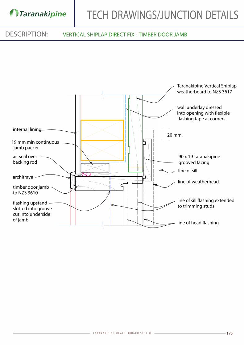
175T A R A N A K I P I N E W E A T H E R B O A R D S Y S T E M
TECH DRAWINGS/JUNCTION DETAILSDESCRIPTION: VERTICAL SHIPLAP DIRECT FIX - TIMBER DOOR JAMB
Taranakipine Vertical Shiplap weatherboard to NZS 3617
timber door jamb to NZS 3610
architrave
internal lining
wall underlay dressed
line of weatherhead
to trimming studs
90 x 19 Taranakipine grooved facing
19 mm min continuous jamb packer
air seal over backing rod
line of sill
slotted into groove cut into underside of jamb
20 mm
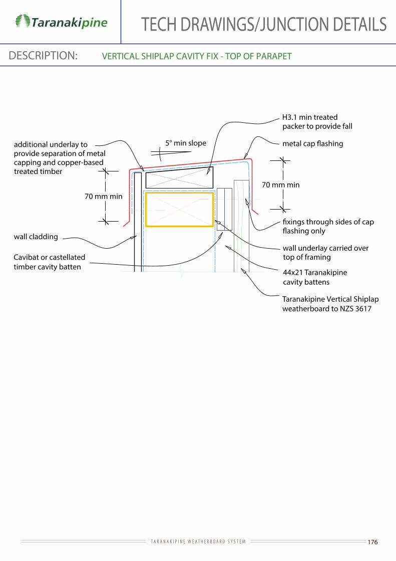
176T A R A N A K I P I N E W E A T H E R B O A R D S Y S T E M
TECH DRAWINGS/JUNCTION DETAILSDESCRIPTION: VERTICAL SHIPLAP CAVITY FIX - TOP OF PARAPET
5° min slope
Taranakipine Vertical Shiplap weatherboard to NZS 3617
wall underlay carried over top of framing
H3.1 min treated packer to provide fall
70 mm min70 mm min
additional underlay to provide separation of metal capping and copper-based treated timber
wall cladding
44x21 Taranakipine cavity battens
Cavibat or castellatedtimber cavity batten
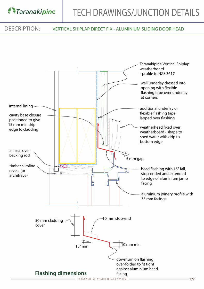
177T A R A N A K I P I N E W E A T H E R B O A R D S Y S T E M
TECH DRAWINGS/JUNCTION DETAILSDESCRIPTION: VERTICAL SHIPLAP DIRECT FIX - ALUMINIUM SLIDING DOOR HEAD
Flashing dimensions
Taranakipine Vertical Shiplapweatherboard
stop-ended and extended to edge of aluminium jamb facing
internal lining
35 mm facings
air seal over backing rod
additional underlay or
wall underlay dressed into
at corners
timber slimline reveal (or architrave)
cavity base closure positioned to give
15 mm min drip edge to cladding
weatherboard - shape to shed water with drip to bottom edge
5 mm gap
against aluminium head facing
50 mm cladding cover
15° min
10 mm stop-end
10 mm min

178T A R A N A K I P I N E W E A T H E R B O A R D S Y S T E M
TECH DRAWINGS/JUNCTION DETAILSDESCRIPTION: VERTICAL SHIPLAP DIRECT FIX - ALUMINIUM SLIDING DOOR JAMB
Taranakipine Vertical Shiplap weatherboard
internal lining
wall underlay dressed
line of weatherhead over
extending to trimming studs
19 mm min continuous jamb packing
air seal over backing rod
35 mm facingstimber slimline reveal (or architrave)
15 mm
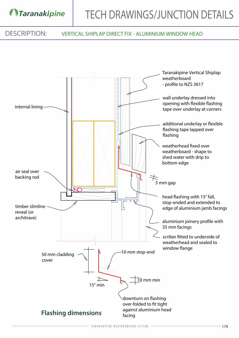
179T A R A N A K I P I N E W E A T H E R B O A R D S Y S T E M
TECH DRAWINGS/JUNCTION DETAILSDESCRIPTION: VERTICAL SHIPLAP DIRECT FIX - ALUMINIUM WINDOW HEAD
Flashing dimensions
Taranakipine Vertical Shiplapweatherboard
wall underlay dressed into
tape over underlay at corners
stop-ended and extended to edge of aluminium jamb facings
internal lining
timber slimline reveal (or architrave)
against aluminium head facing
35 mm facings
weatherboard - shape to shed water with drip to bottom edge
air seal over backing rod
weatherhead and sealed to
50 mm cladding cover
15° min
10 mm stop-end
10 mm min
5 mm gap
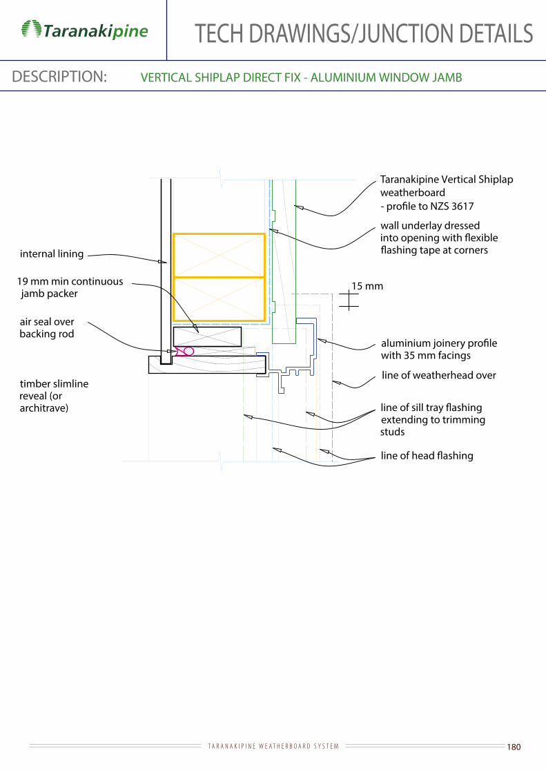
180T A R A N A K I P I N E W E A T H E R B O A R D S Y S T E M
TECH DRAWINGS/JUNCTION DETAILSDESCRIPTION: VERTICAL SHIPLAP DIRECT FIX - ALUMINIUM WINDOW JAMB
Taranakipine Vertical Shiplap weatherboard
internal lining
wall underlay dressed
line of weatherhead over
extending to trimming studs
19 mm min continuous jamb packer
air seal over backing rod
with 35 mm facings
timber slimline reveal (or architrave)
15 mm
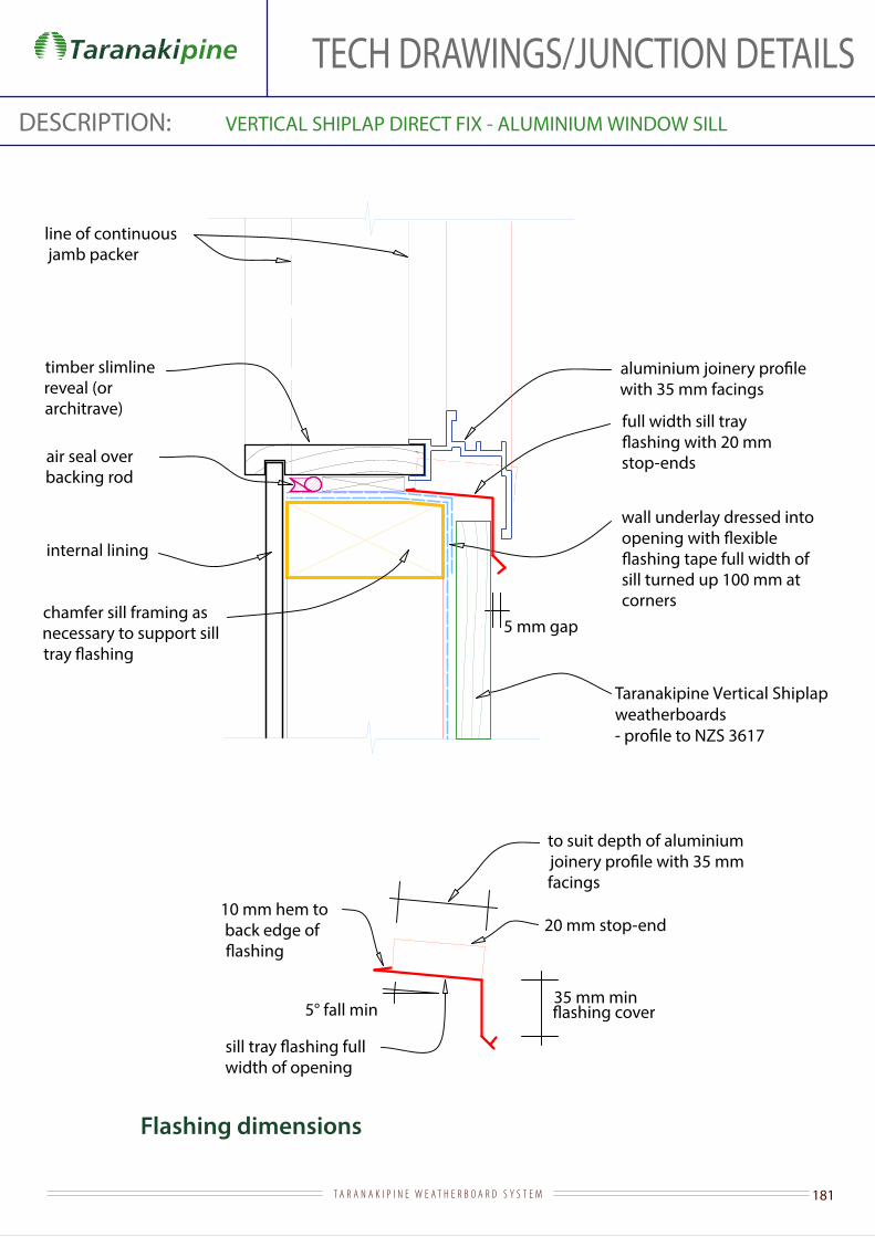
181T A R A N A K I P I N E W E A T H E R B O A R D S Y S T E M
TECH DRAWINGS/JUNCTION DETAILSDESCRIPTION: VERTICAL SHIPLAP DIRECT FIX - ALUMINIUM WINDOW SILL
Flashing dimensions
wall underlay dressed into
sill turned up 100 mm at corners
Taranakipine Vertical Shiplapweatherboards
air seal over backing rod
internal lining
chamfer sill framing as necessary to support sill
with 35 mm facings
to suit depth of aluminium
facings
5° fall min
full width sill tray
stop-ends
10 mm hem to back edge of
timber slimline reveal (or architrave)
line of continuous jamb packer
20 mm stop-end
width of opening
35 mm min
5 mm gap
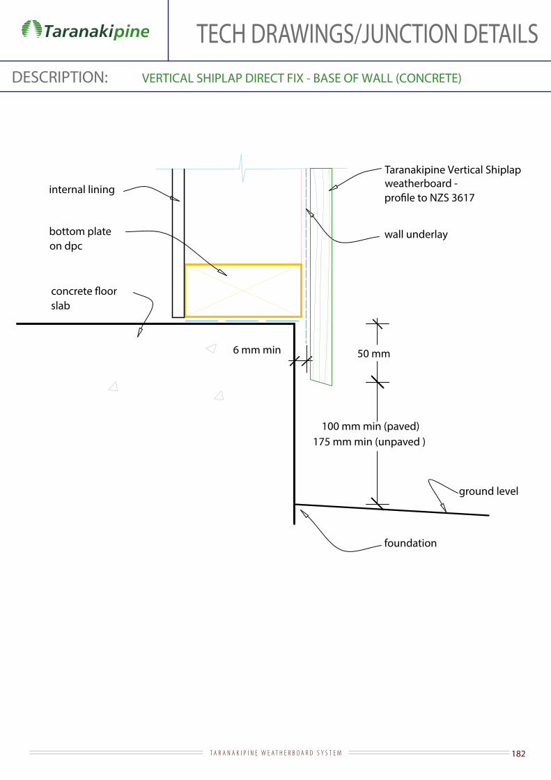
182T A R A N A K I P I N E W E A T H E R B O A R D S Y S T E M
TECH DRAWINGS/JUNCTION DETAILSDESCRIPTION: VERTICAL SHIPLAP DIRECT FIX - BASE OF WALL (CONCRETE)
Taranakipine Vertical Shiplapweatherboard -
ground level
internal lining
slab
foundation
50 mm
100 mm min (paved)175 mm min (unpaved )
wall underlaybottom plate on dpc
6 mm min

183T A R A N A K I P I N E W E A T H E R B O A R D S Y S T E M
TECH DRAWINGS/JUNCTION DETAILSDESCRIPTION: VERTICAL SHIPLAP DIRECT FIX - TIMBER DOOR HEAD
Flashing dimensions
Taranakipine Vertical Shiplapweatherboard to NZS 3617
wall underlay dressed into
at corners
stop-ended and extended 20 mm min beyond outer edge of jamb
internal lining
architrave
timber door head to NZS 3610
jamb facing notched over
underside of weatherhead
weatherboard - shape to shed water with drip to bottom edge and thicker than jamb facings by 6 mm min
air seal over backing rod
additional underlay or
50 mm cladding cover
15° min
to head
10 mm stop-end
5 mm gap
10 mm min

184T A R A N A K I P I N E W E A T H E R B O A R D S Y S T E M
TECH DRAWINGS/JUNCTION DETAILSDESCRIPTION: VERTICAL SHIPLAP CAVITY FIX - TIMBER DOOR JAMB
Taranakipine Vertical Shiplap weatherboard to NZS 3617
timber door jamb to NZS 3610
architrave
internal lining
line of weatherhead over
extended to trimming studs
90 x 19 Taranakipinegrooved facing
19 mm min continuous jamb packing
air seal over backing rod
line of sill
wall underlay dressed
slotted into groove cut into underside of jamb
20 mmCavibat or castellatedtimber cavity batten

185T A R A N A K I P I N E W E A T H E R B O A R D S Y S T E M