tarot zyx 3 axis gyro instruction manual - btcdl.btc.pl/kamami_wa/hk_24522_3.pdf · red led is...
TRANSCRIPT

1
TAROT ZYX 3 AXIS GYRO INSTRUCTION
MANUAL
The multi-functional flybarless ZYX high performance 3-axis gyro system made by TAROT is the
lightest flybarless system. It is compatible with all 200-700 nitro or electric helicopters, and support 90, 120,
135, and 140 degrees CCPM swashplate systems. Furthermore, it is compatible with all servos, and
support firmware update. The setup procedure is quite simple, and can be completed in ten minutes.
ZYX 3-axis gyro system provides two operational flying modes, which can suit pilots from beginners to
professionals. ZYX 3-axis gyro system has several setting options; pilots can adjust the parameter of
swashplate and rudder servo, which give pilots the impressive experience of the flybarless helicopter.
ZYX high performance 3-gyro system uses MEMS gyro sensor which can bear bad weather condition
and pilots can control helicopter precisely. With built-in pirouette flip optimization function, the speed of
pirouette is really stable. The helicopter will keep at one point without shifting in pirouettes flip.
1. Specifications
Dimensions: 37.2mm*25.2mm*13mm
Weight: 9.8g
Operating voltage: DC 3.5V-9V
Operating current drain: 60mA
Operating temperature:-15℃~65℃
Maximal angular velocity: 800 degrees/sec
Tail servo compatibility: 1.52ms analog servo, 1.52ms digital servo, 760us digital servo, 960us digital servo
Cyclic servo compatibility: 1.52ms analog servo, 1.52ms digital servo
Radio compatibility: PPM, PCM, 2.4G
Supporting firmware upgrade
Supporting Multi-Blade Rotor Head
2
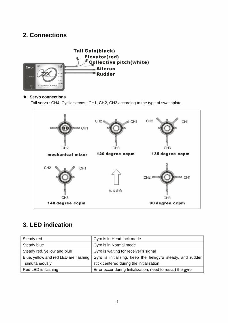
2. Connections
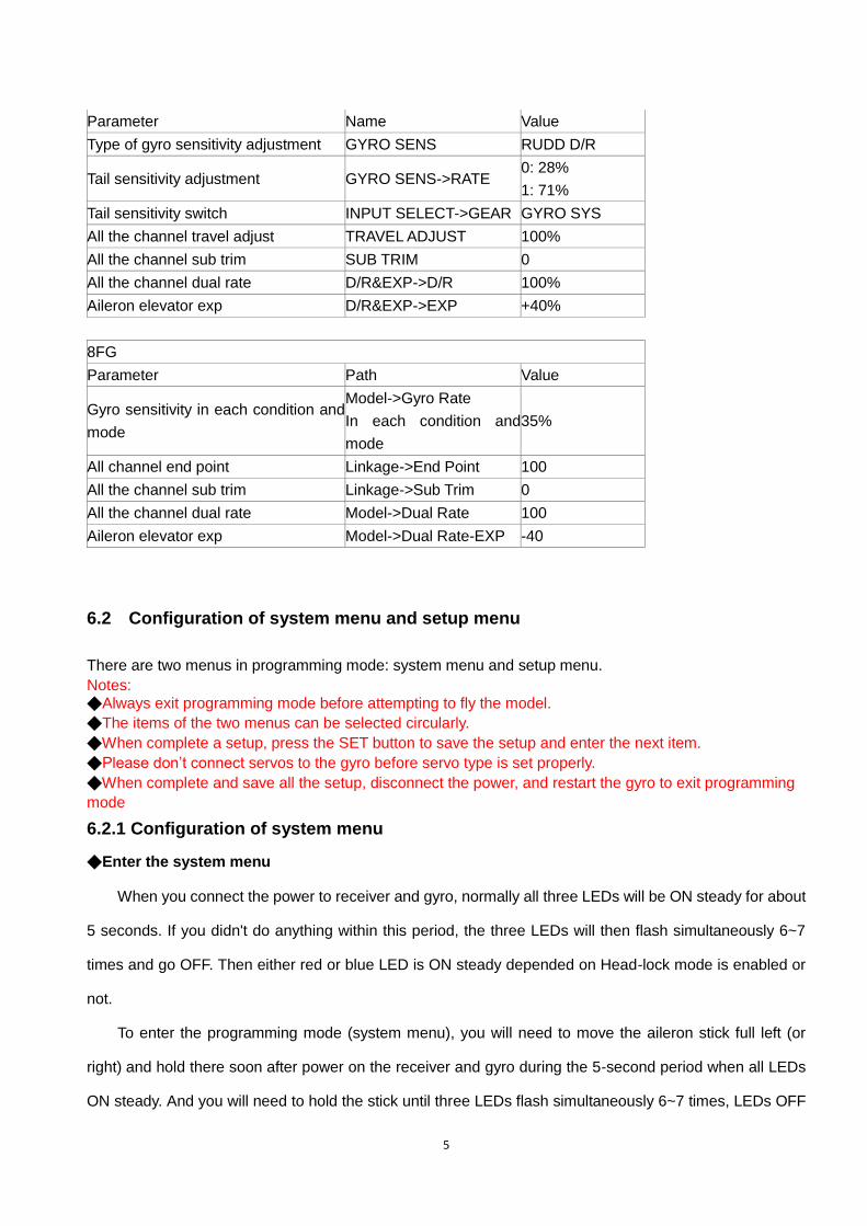
◆ Servo connections
Tail servo : CH4. Cyclic servos : CH1, CH2, CH3 according to the type of swashplate.
3. LED indication
Steady red Gyro is in Head-lock mode
Steady blue Gyro is in Normal mode
Steady red, yellow and blue Gyro is waiting for receiver’s signal
Blue, yellow and red LED are flashing
simultaneously
Gyro is initializing, keep the heli/gyro steady, and rudder
stick centered during the initialization.
Red LED is flashing Error occur during Initialization, need to restart the gyro

3
4. Gyro mounting
◆ The gyro should be mounted at a flat position which is perpendicular to the main shaft and far away
from the engine and other electric devices.
◆ Mount the gyro to the flat position by using a sponge double sided tape, arrange the cable of gyro
loosely to reduce transmission of vibrations through the cable. Do not allow the gyro case to touch
other parts of the helicopter.
Mounting on a small electric helicopter: use a 2-3mmm foam pad.
Mounting on a large or a High vibration helicopters: use a 2-3mmm foam pad on each side of the
damping shield plate.
◆ There are three directions to be selected for mounting the gyro (the gyro need to be configured
accordingly later).
Direction 1: Direction 2: Direction 3:
5. Installation of servo horns and linkages
◆ Make sure all the mechanical parts of the rotor head, the swashplate and the tail rotor are
installed correctly, all parts can move smoothly, and all the servos are installed firmly.
◆ Install the linkage balls to cyclic servo horns. We recommend the distance from the ball to center is:
12.5-13mm (250,450size), 14-14.5mm (500size), 14.5-15mm (600 or larger size).

4
◆ Install the linkage ball to tail servo horn. We recommend the distance from the ball to center is: 4.5mm
(250size), 7.5-10mm (450, 500size),13.5-15mm(600 or larger size) .
◆ Install the horn to tail servo temporarily, adjust the horn position to make it perpendicular to the linkage,
then set the tail pitch to be approximately 8°in the direction that compensates the main rotor torque by
adjusting the linkage length.
Note: Don’t connect servos to the gyro in this stage.
6. Gyro setup through transmitter
6.1. Transmitter configuration
Power on the transmitter and create a new helicopter mode, set the trims and sub-trims of all the channels
to be zero. Select the swashplate type as a non-mixing mode(Futaba:H1;JR:1 servo NORM)in your
transmitter. Make sure all the mixing functions related to swashplate and tail are disable (turned off). Do not
adjust the collective pitch curve now, remain it as a straight line.
Take DX7 and 8FG for example, the initial configurations are shown below.
DX7
5
Parameter Name Value
Type of gyro sensitivity adjustment GYRO SENS RUDD D/R
Tail sensitivity adjustment GYRO SENS->RATE 0: 28%
1: 71%
Tail sensitivity switch INPUT SELECT->GEAR GYRO SYS
All the channel travel adjust TRAVEL ADJUST 100%
All the channel sub trim SUB TRIM 0
All the channel dual rate D/R&EXP->D/R 100%
Aileron elevator exp D/R&EXP->EXP +40%
8FG
Parameter Path Value
Gyro sensitivity in each condition and
mode
Model->Gyro Rate
In each condition and
mode
35%
All channel end point Linkage->End Point 100
All the channel sub trim Linkage->Sub Trim 0
All the channel dual rate Model->Dual Rate 100
Aileron elevator exp Model->Dual Rate-EXP -40
6.2 Configuration of system menu and setup menu
There are two menus in programming mode: system menu and setup menu.
Notes: ◆Always exit programming mode before attempting to fly the model.
◆The items of the two menus can be selected circularly.
◆When complete a setup, press the SET button to save the setup and enter the next item.
◆Please don’t connect servos to the gyro before servo type is set properly.
◆When complete and save all the setup, disconnect the power, and restart the gyro to exit programming
mode
6.2.1 Configuration of system menu
◆Enter the system menu
When you connect the power to receiver and gyro, normally all three LEDs will be ON steady for about
5 seconds. If you didn't do anything within this period, the three LEDs will then flash simultaneously 6~7
times and go OFF. Then either red or blue LED is ON steady depended on Head-lock mode is enabled or
not.
To enter the programming mode (system menu), you will need to move the aileron stick full left (or
right) and hold there soon after power on the receiver and gyro during the 5-second period when all LEDs
ON steady. And you will need to hold the stick until three LEDs flash simultaneously 6~7 times, LEDs OFF
6
for a couple seconds, AND three LED flash again SEQUENTIALLY. The gyro is now in programming mode
and all LEDs will go off again. You will then release the stick back to center. At this moment, you may then
press the SET button. Everytime when you press the SET button, all three LEDs will flash simultaneously
and followed by yellow flash. The number of flash will indicate the item you are currently with.
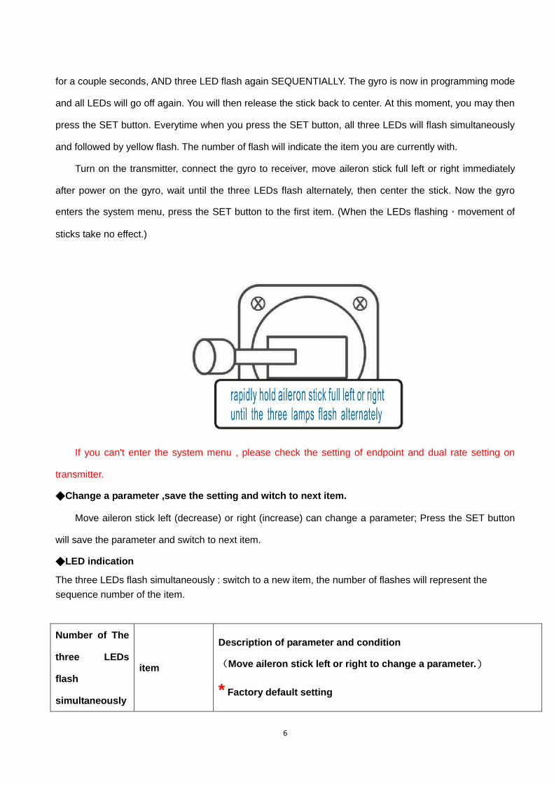
Turn on the transmitter, connect the gyro to receiver, move aileron stick full left or right immediately
after power on the gyro, wait until the three LEDs flash alternately, then center the stick. Now the gyro
enters the system menu, press the SET button to the first item. (When the LEDs flashing,movement of
sticks take no effect.)
If you can't enter the system menu , please check the setting of endpoint and dual rate setting on
transmitter.
◆Change a parameter ,save the setting and witch to next item.
Move aileron stick left (decrease) or right (increase) can change a parameter; Press the SET button
will save the parameter and switch to next item.
◆LED indication
The three LEDs flash simultaneously : switch to a new item, the number of flashes will represent the
sequence number of the item.
Number of The
three LEDs
flash
simultaneously
item
Description of parameter and condition
(Move aileron stick left or right to change a parameter.)
* Factory default setting
7
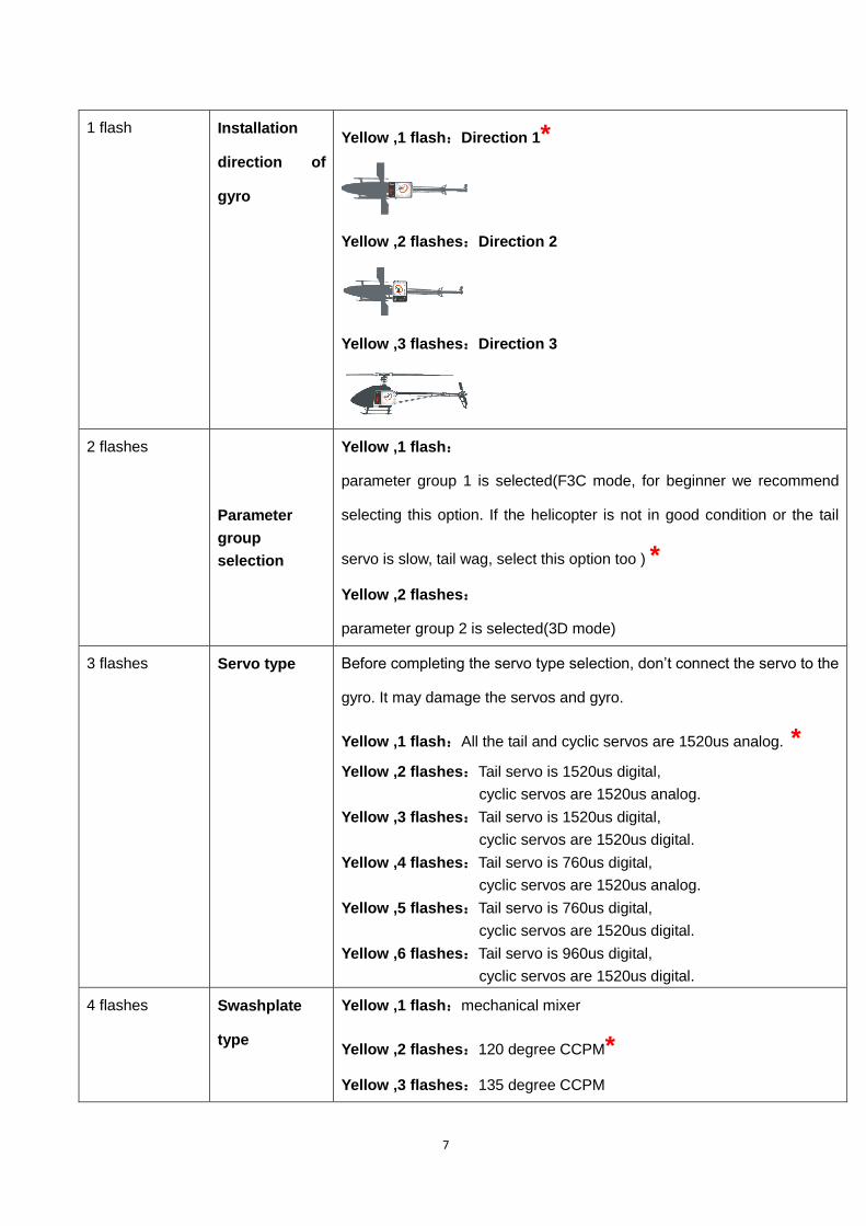
1 flash Installation
direction of
gyro
Yellow ,1 flash:Direction 1*
Yellow ,2 flashes:Direction 2
Yellow ,3 flashes:Direction 3
2 flashes
Parameter
group
selection
Yellow ,1 flash:
parameter group 1 is selected(F3C mode, for beginner we recommend
selecting this option. If the helicopter is not in good condition or the tail
servo is slow, tail wag, select this option too ) *
Yellow ,2 flashes:
parameter group 2 is selected(3D mode)
3 flashes Servo type Before completing the servo type selection, don’t connect the servo to the
gyro. It may damage the servos and gyro.
Yellow ,1 flash:All the tail and cyclic servos are 1520us analog. *
Yellow ,2 flashes:Tail servo is 1520us digital,
cyclic servos are 1520us analog.
Yellow ,3 flashes:Tail servo is 1520us digital,
cyclic servos are 1520us digital.
Yellow ,4 flashes:Tail servo is 760us digital,
cyclic servos are 1520us analog.
Yellow ,5 flashes:Tail servo is 760us digital,
cyclic servos are 1520us digital.
Yellow ,6 flashes:Tail servo is 960us digital,
cyclic servos are 1520us digital.
4 flashes Swashplate
type
Yellow ,1 flash:mechanical mixer
Yellow ,2 flashes:120 degree CCPM*
Yellow ,3 flashes:135 degree CCPM
8
Yellow ,4 flashes:140 degree CCPM
Yellow ,5 flashes:90 degree CCPM
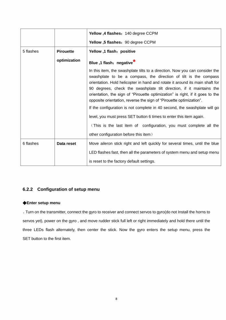
5 flashes Pirouette
optimization
Yellow ,1 flash:positive
Blue ,1 flash:negative*
In this item, the swashplate tilts to a direction. Now you can consider the
swashplate to be a compass, the direction of tilt is the compass
orientation. Hold helicopter in hand and rotate it around its main shaft for
90 degrees, check the swashplate tilt direction, if it maintains the
orientation, the sign of “Pirouette optimization” is right, if it goes to the
opposite orientation, reverse the sign of “Pirouette optimization”.
If the configuration is not complete in 40 second, the swashplate will go
level, you must press SET button 6 times to enter this item again.
(This is the last item of configuration, you must complete all the
other configuration before this item)
6 flashes Data reset Move aileron stick right and left quickly for several times, until the blue
LED flashes fast, then all the parameters of system menu and setup menu
is reset to the factory default settings.
6.2.2 Configuration of setup menu
◆Enter setup menu
。Turn on the transmitter, connect the gyro to receiver and connect servos to gyro(do not Install the horns to
servos yet), power on the gyro , and move rudder stick full left or right immediately and hold there until the
three LEDs flash alternately, then center the stick. Now the gyro enters the setup menu, press the
SET button to the first item.

9
If you can't enter the setup menu, please check the setting of endpoint and dual
rate setting on transmitter.
◆Change a parameter ,save the parameter and switch to next item.
Move aileron stick left or right can change the sequence number of the parameter in a item; Move
rudder stick left or right can change the parameter; Press the SET button will save the parameter and
switch to next item. (When the LEDs flashing, the movement of sticks take no effect.)
◆LED indication
The three LEDs flash simultaneously : switch to a new item, the number of flashes is the sequence number
of the item.
In a item ,red flash indicates the sequence number of the parameter.
In item1、3、4、6、7, fast yellow flashes indicate parameter value increasing, fast blue flashes indicate value
decreasing. Every flash means the change is one
Number of The
three LEDs
flash
simultaneously
item Description of parameter and condition
1 flash Gyro gain of
3 axis
Move aileron stick left or right can select the axis; Move rudder stick left
or right to change the gain value; adjustment range is 10~125.
Red,1 flash : tail gain(default value:F3C 70; 3D 100)
Red,2 flashes : roll gain(default value:F3C 40; 3D 40)
Red,3 flashes : pitch gain(default value:F3C 40; 3D 40)
10
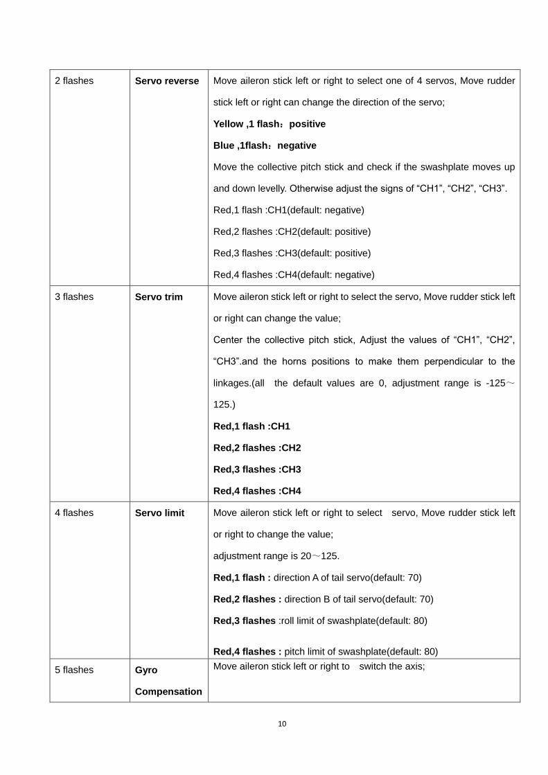
2 flashes Servo reverse Move aileron stick left or right to select one of 4 servos, Move rudder
stick left or right can change the direction of the servo;
Yellow ,1 flash:positive
Blue ,1flash:negative
Move the collective pitch stick and check if the swashplate moves up
and down levelly. Otherwise adjust the signs of “CH1”, “CH2”, “CH3”.
Red,1 flash :CH1(default: negative)
Red,2 flashes :CH2(default: positive)
Red,3 flashes :CH3(default: positive)
Red,4 flashes :CH4(default: negative)
3 flashes Servo trim Move aileron stick left or right to select the servo, Move rudder stick left
or right can change the value;
Center the collective pitch stick, Adjust the values of “CH1”, “CH2”,
“CH3”.and the horns positions to make them perpendicular to the
linkages.(all the default values are 0, adjustment range is -125~
125.)
Red,1 flash :CH1
Red,2 flashes :CH2
Red,3 flashes :CH3
Red,4 flashes :CH4
4 flashes Servo limit Move aileron stick left or right to select servo, Move rudder stick left
or right to change the value;
adjustment range is 20~125.
Red,1 flash : direction A of tail servo(default: 70)
Red,2 flashes : direction B of tail servo(default: 70)
Red,3 flashes :roll limit of swashplate(default: 80)
Red,4 flashes : pitch limit of swashplate(default: 80)
5 flashes Gyro
Compensation
Move aileron stick left or right to switch the axis;
11
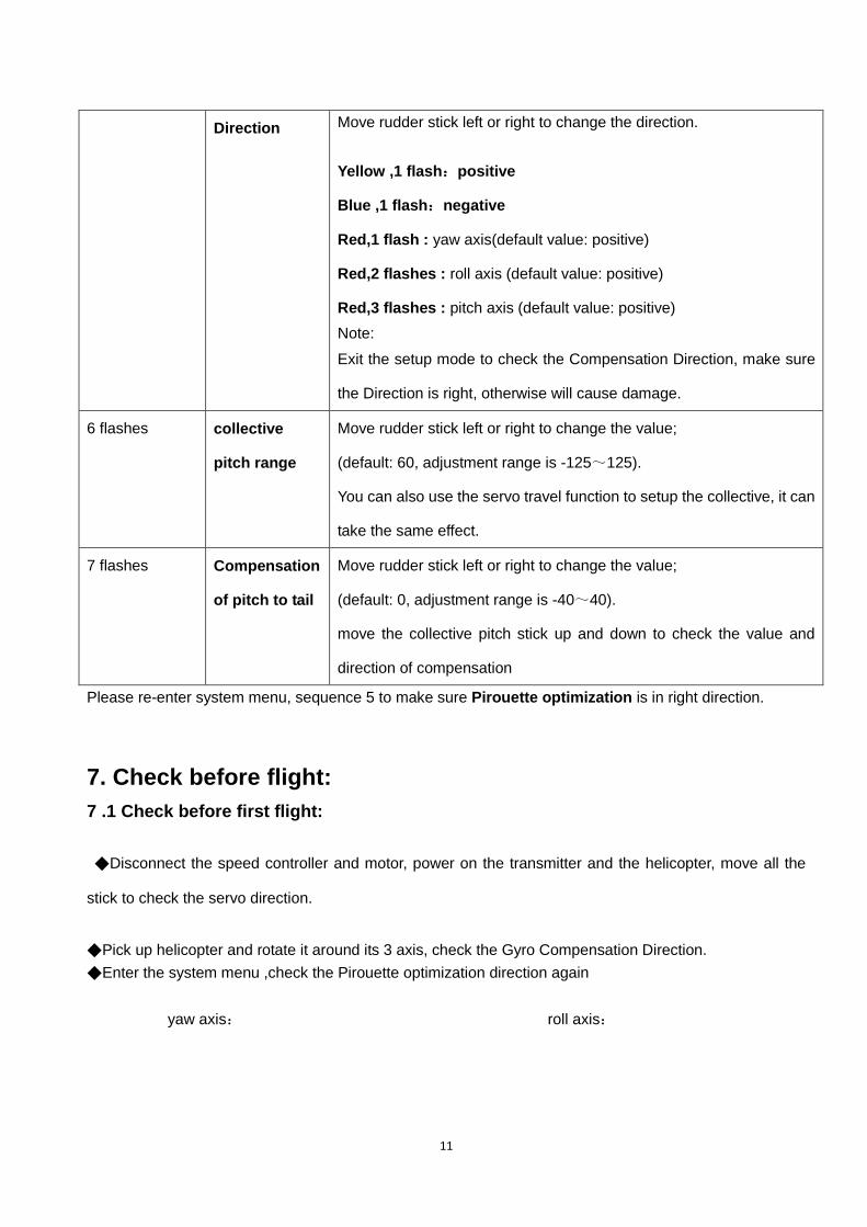
Direction Move rudder stick left or right to change the direction.
Yellow ,1 flash:positive
Blue ,1 flash:negative
Red,1 flash : yaw axis(default value: positive)
Red,2 flashes : roll axis (default value: positive)
Red,3 flashes : pitch axis (default value: positive)
Note:
Exit the setup mode to check the Compensation Direction, make sure
the Direction is right, otherwise will cause damage.
6 flashes collective
pitch range
Move rudder stick left or right to change the value;
(default: 60, adjustment range is -125~125).
You can also use the servo travel function to setup the collective, it can
take the same effect.
7 flashes Compensation
of pitch to tail
Move rudder stick left or right to change the value;
(default: 0, adjustment range is -40~40).
move the collective pitch stick up and down to check the value and
direction of compensation
Please re-enter system menu, sequence 5 to make sure Pirouette optimization is in right direction.
7. Check before flight:
7 .1 Check before first flight:
◆Disconnect the speed controller and motor, power on the transmitter and the helicopter, move all the
stick to check the servo direction.
◆Pick up helicopter and rotate it around its 3 axis, check the Gyro Compensation Direction.
◆Enter the system menu ,check the Pirouette optimization direction again
yaw axis: roll axis:
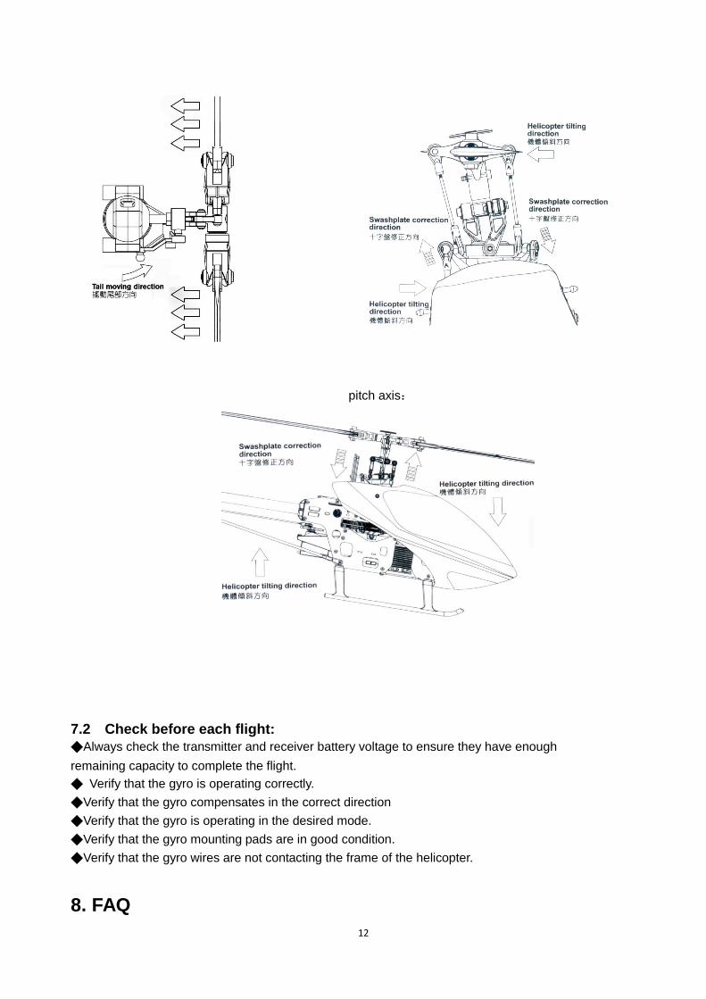
12
pitch axis:
7.2 Check before each flight:
◆Always check the transmitter and receiver battery voltage to ensure they have enough
remaining capacity to complete the flight.
◆ Verify that the gyro is operating correctly.
◆Verify that the gyro compensates in the correct direction
◆Verify that the gyro is operating in the desired mode.
◆Verify that the gyro mounting pads are in good condition.
◆Verify that the gyro wires are not contacting the frame of the helicopter.
8. FAQ
13
◆Tail oscillate quickly(tail wag, hunting).
• Make sure the helicopter is in good mechanical condition. All shafts must absolutely straight. Limit the vibration
as low as possible. Make sure the tail rotor pushrod is straight.
• Decrease the gyro sensitivity setting on transmitter until 15%(JR:57%).
• Select parameter group 1 (F3C mode) in system menu
◆Helicopter swing randomly.
•Make sure the helicopter is in good mechanical condition. All shafts must absolutely straight. Limit the
vibration as low as possible.
•Use the accessory shield plate and mounting pad. A coin also is OK.
•Decrease the setting of gain parameter within gyro.
◆Rotate uncontrollable.
•Check the Installation direction of gyro
•Check the Gyro Compensation Direction
•Move all the stick to check the servo direction.
◆Rotate on a direction slowly and continually, drift.
When power on, the gyro needs several seconds to initialize. During initialization, Remain the airframe
immobile and the aileron elevator and rudder stick centered, red yellow and blue LEDs flash simultaneously.
When initialization complete, the tail servo will move right and then left to indicate.
Quickly dial the gain switch between Normal Mode and head-lock Mode for several times, the gyro will
initialize again
◆Red LED keep flashing
Error occur during Initialization, Restart the gyro (power off then on again). Remain the airframe immobile and
the aileron elevator and rudder stick centered during initialization
◆Helicopter unstable when fast Pirouette
Enter the system menu,check the Pirouette optimization direction again