tcp trunking for bandwidth management of aggregate traffic
TRANSCRIPT

TCP Trunking for Bandwidth Management of Aggregate Traffic
Abstract
TCP trunking is a novel way of applying TCP conges-tion control to bandwidth management of aggregate traffic.This is accomplished by setting up a separate TCP connec-tion to probe network congestion, and then using the TCPconnection’s congestion control to regulate the bandwidthusage of the aggregate traffic.
TCP trunking offers several advantages in managingbandwidth of aggregate traffic. It can dynamically allocatebandwidth to competing traffic aggregates in a fair manner,while assuring no loss of user packets due to networkcongestion. In addition, it can transmit user packets atguaranteed rates for traffic aggregates. Implementationdetails and experimental results are described in the paper.
1. Introduction
Traffic aggregation has been an essential technique inmanaging backbone networks of the Internet. It can reducethe number of states that backbone nodes need to maintainfor routing [3] and for providing quality of service (QoS) [4,5]. It can also reduce the number of flows that backbonesneed to handle, in order to lower packet loss rates [6].
As aggregate flows become widely used, their conges-tion control will be important. Traditionally TCP has beenthe dominant protocol that provides congestion control forindividual flows between end hosts. In this paper we showthat TCP is also suited in providing congestion control foraggregate flows between network nodes.
Our approach, which we call TCP trunking, uses aseparate TCP connection to provide congestion control foraggregate traffic. The TCP trunking approach offers severaladvantages. For example, it can provide fair and dynamicbandwidth allocation as well as guaranteed transmissionrates for traffic aggregates, while assuring no loss of userpackets due to network congestion.
Author names are listed in alphabetical order.
An earlier version of this paper [1] was presented at the ICNP’99conference. More details about TCP trunking can be found in [2].
1
This paper is organized as follows: Section 2 gives anoverview of TCP trunks. Section 3 presents the design goalsfor TCP trunking. Section 4 describes our implementation ofTCP trunks. Buffer management algorithms for routers onthe path of a TCP trunk and at its sender are discussed inSections 5 and 6. In Section 7, we describe TCP trunkingexperiments on laboratory testbed networks and reportmeasured performance results. Section 8 discusses relatedwork. Section 9 concludes the paper.
2. Overview of TCP Trunks
A TCP trunk is a network path which carries traffic ofmultiple user flows and has its total bandwidth usage regu-lated by the TCP congestion control algorithm. For a four-node IP network of Figure 1 (a), Figure 1 (b) shows two TCPtrunks: tcp-trunk-1 from A to C and tcp-trunk-2 from D to B.
Figure 1 (c) depicts that tcp-trunk-1 carries two TCP user
A C
D
B
A C
D
B
tcp-trunk-2
tcp-trunk-1
A
D
B
tcp-1
tcp-2
tcp-1
tcp-2
(a) (b)
(c)
TCP TrunkSender
tcp-trunk-1
Figure 1. (a) An IP network; (b) two TCP trunks over thenetwork; and (c) two user flows (tcp-1 and tcp-2) overtcp-trunk-1.
C
TCP TrunkReceiver
H.T. Kung
[email protected] of Engineering and Applied Sciences
Harvard UniversityCambridge, MA 02138, USA
S.Y. Wang
[email protected] of Computer Science and Info. Engr.
National Chiao Tung UniversityHsinchu, Taiwan

flows: tcp-1 and tcp-2. We call packets of these user flowsuser packets.
To implement TCP congestion control of a TCP trunk,a management TCP connection (also called managementTCP for simplicity) is set up. The sender and receiver of thismanagement TCP connection are called the trunk senderand receiver, respectively. For example, in Figure 1 (c), tcp-trunk-1’s sender and receiver are on A and C, respectively.
Packets of the management TCP are managementpackets. Since the management TCP is only for congestioncontrol purposes, a management packet contains only aTCP/IP header and carries no TCP payload. As in a normalTCP connection, based on received acknowledgmentpackets or their absence, the trunk sender uses a congestionwindow to determine the sending rate of managementpackets.
In turn, the sending rate of management packets deter-mines that of user packets. That is, only each time afterhaving sent a management packet, the trunk sender willsend some additional number (VMSS of Section 4.1) ofbytes of user packets. In this way the management TCPregulates the sending rate of user packets of the trunk.
The routing path taken by a TCP trunk is called thepath of the trunk. For example, the path of tcp-trunk-1 isfrom A to B and to C. The path of a TCP trunk is normally alayer-2 circuit. In the future, it can also be an MPLS path [7,8]. The use of layer-2 circuits or MPLS paths ensures thatuser and management packets of a TCP trunk will take thesame path. This allows the use of management packets toprobe congestion level of the path for user packets.
3. Design Goals for TCP Trunks
In this section, we describe design goals for TCPtrunks. For each goal, we list those sections and figures inthe paper which discuss and demonstrate how it is achieved.
G1. Guaranteed and elastic bandwidth. See Section 4 forimplementation, and Figures 4 and 5 for experimentalresults.
- Guaranteed minimum bandwidth (GMB): Suppose thatvia a separate admission control mechanism (a topicbeyond the scope of this paper), a TCP trunk is given aguaranteed minimum bandwidth on every hop of itspath. Then the trunk sender can send its user packets atleast at this rate at all time.
- Elastic bandwidth: Beyond GMB, a TCP trunk can grabadditional network bandwidth when it is available. Thisproperty can also keep the overall network utilizationhigh.
G2. Flexible and fine-grained bandwidth allocation. SeeSection 4 for implementation, and Figures 4 and 5 forexperimental results.
- By choosing proper VMSS values, competing TCPtrunks can share the available bandwidth flexibly, in anydesired proportion and in any granularity. For example,if trunk 1 and trunk 2’s VMSSs are 1,500 and 500respectively, then the achieved bandwidth of trunk 1will be about 1500/500 = 300% times that of trunk 2. Iftrunk 1 and trunk 2’s VMSSs are 1500 and 1499 respec-tively, then the achieved bandwidth of trunk 1 is about1500/1499 = 1.000667% times that of trunk 2.
G3. High-speed, low latency, and in-sequence forwarding.See Section 4 for implementation.
- The TCP sender and receiver will forward arriving userpackets immediately to the next hop as is and in-sequence.
G4. Lossless delivery. See Section 5 for required buffermanagement and provisioning in routers, and Figure 6 forexperimental results.
- Suppose that routers on the trunk path can differentiatemanagement and user packets by packet marking, andduring congestion, they can drop management packetsbefore user packets. (This capability is similar to whatrouters supporting diff-serv [4, 5] can do.) Then TCPtrunking guarantees that user packets will not bedropped inside routers due to congestion.
G5. Traffic aggregation and isolation. See Figure 7 forhierarchical TCP trunking, and Figure 10 and Figure 12 forexperimental results.
- A TCP trunk uses a single TCP connection to providecongestion control for multiple TCP user flows. Thisreduces the total number of competing TCP flows on abackbone network. This can reduce packet drop rates inthe backbone [6].
- When carrying UDP user flows, a TCP trunk can isolatethem from other competing flows. Note that UDP flowsfor multimedia streaming applications are usually not“TCP-friendly” [9], that is, they do not employeeadequate congestion control. By containing them in aTCP trunk (perhaps with some GMB), these congestionunresponsive UDP flows can no longer starve othercompeting TCP flows.
- When carrying “fragile” short-lived TCP user flowssuch as transfers of small Web pages, a TCP trunk canprotect them from competing large flows. These fragileflows can thus experience reduced delays and packetloss rates.
- When carrying aggregate traffic from multiple usersites, TCP trunks can ensure fair use of a backbone inde-pendent of the number of TCP users flows a site mayhave.
To validate the TCP trunking approach, we have imple-mented it on FreeBSD 2.2.8 machines. We have constructed
2
laboratory testbeds with nodes based on these FreeBSDmachines. We have done TCP trunking experiments onthese testbeds. In addition, we have performed intensivesimulations on the Harvard TCP/IP network simulator [10]for large network configurations. The simulation results areconsistent with the experimental results reported in Section7.
In the rest of this paper we describe our TCP trunkingimplementation, discuss its design considerations, andreport experimental results obtained on our testbeds.
4. TCP Trunking Implementation
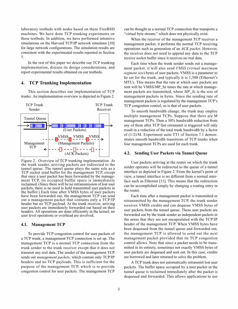
This section describes our implementation of TCPtrunks. An implementation overview is depicted in Figure 2.
4.1. Management TCP
To provide TCP congestion control for user packets ofa TCP trunk, a management TCP connection is set up. Themanagement TCP is a normal TCP connection from thetrunk sender to the trunk receiver except that it does nottransmit any real data. The sender of the management TCPsends out management packets, which contain only TCP/IPheaders and no TCP payloads. This is sufficient for thepurpose of the management TCP, which is to providecongestion control for user packets. The management TCP
can be thought as a normal TCP connection that transports a“virtual byte stream,” which does not physically exist.
When the receiver of the management TCP receives amanagement packet, it performs the normal TCP receivingoperations such as generation of an ACK packet. However,the receiver does not need to append any data to the TCPreceive socket buffer since it receives no real data.
Each time when the trunk sender sends out a manage-ment packet, it will also send VMSS (virtual maximumsegment size) bytes of user packets. VMSS is a parameter tobe set for the trunk, and typically it is 1,500 (Ethernet’sMTU). This means that the rate at which user packets aresent will be VMSS/MP_Sz times the rate at which manage-ment packets are transmitted, where MP_Sz is the size ofmanagement packets in bytes. Since the sending rate ofmanagement packets is regulated by the management TCP’sTCP congestion control, so is that of user packets.
To smooth bandwidth change, the trunk may employmultiple management TCPs. Suppose that there are Mmanagement TCPs. Then a 50% bandwidth reduction fromany of them after TCP fast retransmit is triggered will onlyresult in a reduction of the total trunk bandwidth by a factorof (1/2)/M. Experiment suite TT1 of Section 7.1 demon-strates smooth bandwidth transitions of TCP trunks whenfour management TCPs are used for each trunk.
4.2. Sending User Packets via Tunnel Queue
User packets arriving at the router on which the trunksender operates will be redirected to the queue of a tunnelinterface as depicted in Figure 2. From the kernel’s point ofview, a tunnel interface is no different from a normal inter-face such as Ethernet [11]. This means that the redirectioncan be accomplished simply by changing a routing entry inthe router.
Each time after a management packet is transmitted orretransmitted by the management TCP, the trunk senderreceives VMSS credits and can dequeue VMSS bytes ofuser packets from the tunnel queue. These user packets areforwarded out by the trunk sender as independent packets inthe sense that they are not encapsulated with the TCP/IPheader of the management TCP. When VMSS bytes havebeen dequeued from the tunnel queue and forwarded out,the management TCP is allowed to send out the nextmanagement packet provided that its TCP congestioncontrol allows. Note that since a packet needs to be trans-mitted in its entirety, sometimes not exactly VMSS bytes ofuser packets are dequeued and sent out. In this case, creditsare borrowed and later returned to solve the problem.
A TCP trunk does not automatically retransmit lost userpackets. The buffer space occupied by a user packet in thetunnel queue is reclaimed immediately after the packet isdequeued and forwarded. This allows applications to use
Figure 2. Overview of TCP trunking implementation. Atthe trunk sender, arriving packets are redirected to thetunnel queue. The tunnel queue plays the same role as aTCP socket send buffer for the management TCP, exceptthat once a user packet has been forwarded by the manage-ment TCP, its occupied buffer space is immediatelyreclaimed. (Since there will be no retransmission of lost userpackets, there is no need to hold transmitted user packets inthe buffer.) Each time after VMSS bytes of user packetshave been forwarded out, the management TCP can sendout a management packet that contains only a TCP/IPheader but no TCP payload. At the trunk receiver, arrivinguser packets are immediately forwarded out based on theirheaders. All operations are done efficiently in the kernel; nouser level operations or overhead are involved.
Tunnel Queue
VMSS VMSS VMSS
Management
TCP Trunk
TCP
(User Packets)
(Management Packets)
(ACK Packets)
TCP TrunkSender Receiver
3

different retransmission policies based on their own reli-ability requirements. (E.g., FTP requires reliable datatransfer whereas video-conferencing can live with unreli-able transfer.) For some real-time applications such as videoconferencing, retransmitted packets may arrive at thereceiver too late to be useful, and thus will only wastenetwork bandwidth. Therefore when retransmitting userpackets is desired, it will be handled by applications at theend hosts. In contrast, for the management TCP which isused to probe network congestion, a lost managementpacket must be retransmitted to keep the probe going.
It is important that user and management packetstraverse on the same trunk path so that the congestion leveldetected by probing management packets is applicable touser packets. For example, if the trunk path is on top of alayer-2 circuit or an MPLS path, then these packets willhave layer-2 or shim header with the same circuit identifieror path label, respectively, to ensure that user and manage-ment packets use the same path.
4.3. TCP Trunking with Guaranteed MinimumBandwidth
Suppose that via admission control and bandwidthreservation the network can provide a guaranteed minimumbandwidth (GMB) of X bytes per millisecond for a TCPtrunk. We describe how the trunk sender can send userpackets at the GMB rate, while being able to send additionaluser packets under TCP congestion control when extrabandwidth is available.
The trunk sender uses a GMB controller equipped witha timer. The GMB controller attempts to send some numberof user packets from the tunnel queue each time the timerexpires. (In our implementation, the timer is set to be 1millisecond.) When the timer expires, if there are packets inthe tunnel queue, the GMB controller will send some ofthem under the control of a leaky bucket algorithm. Theobjective here is that, for any time interval of Y millisec-onds, if there is a sufficient number of bytes to be sent fromthe tunnel queue, the total number of bytes actually sent bythe GMB controller will approach the target of X*Y.
For each expiration of the GMB timer, after the GMBcontroller has finished sending all the user packets that it issupposed to send, if there are still packets left in the tunnelqueue, they will be sent out under the control of themanagement TCP as described in Section 4.1.
In this manner, the sender will send user packets atGMB under the control of the GMB controller and, at thesame time, dynamically share the available network band-width under the control of the management TCP.
5. Buffer Management and Provisioning inRouters
To work with TCP trunks, a router’s buffer can be assimple as a single FIFO queue for all TCP trunks’ user andmanagement packets. The router uses the following buffermanagement scheme to prevent loss of user packets due tobuffer overflow. When the FIFO queue occupancy starts tobuild up, the router will drop some incoming managementpackets. Dropping these management packets will triggertheir corresponding TCP trunk senders to reduce theirsending rates of user packets and thus lower the congestionlevel. The router does the packet dropping sufficiently earlyto ensure that before the buffer is full, the congestion levelwill have been lowered so that buffer overflow will nothappen.
More precisely, the router will drop a managementpacket when the number of management packets in thebuffer exceeds a certain threshold MP_Th. Following thearguments of [6], we set:
MP_Th = α*N (1)
where N is the expected number of active managementTCPs that will use the buffer at the same time, and α is thenumber of packets that the congestion window of a TCPconnection must have in order to avoid frequent time-outs.A reasonable choice for α would be 8. This is because if aTCP connection has 8 or more packets in its congestionwindow, chances that the fast retransmit and recoverymechanism can recover from a single packet loss are prettygood [12]. Because experimental results show that use ofRED [13] can lower the value of α somewhat, for all of ourexperiments reported in this paper, a simple RED-likescheme is used in routers.
Given α and N, under the condition that the routeralways keeps the number of management packets belowMP_Th, we can compute the maximum buffer occupancy,Require_BS, in Equation (2) below. By configuring therouter buffer to be larger than Require_BS, we can ensurethat no user packets will be dropped due to buffer overflow.That is, only management packets will be dropped duringcongestion, not user packets.
Let MP_Sz be the size of a management packet inbytes. Three types of packets may occupy the buffer of arouter. We consider their maximum buffer occupancyrespectively as follows.
(1) Management packets
The maximum buffer occupancy of these packets is:
MP_BS = MP_Th*MP_Sz
4

(2) User packets sent under management TCP control
The maximum buffer occupancy of these packets is:
UP_BS_TCP=MP_BS*(VMSS/MP_Sz) + N*VMSS
The first term reflects the fact that a user packet isVMSS/MP_Sz times larger than a management packet.The second term takes into account the situation thateach of the N management TCPs has sent out VMSS-byte user packets but not the corresponding manage-ment packet.
(3) User packets sent under GMB control
Let the maximum buffer occupancy of these packets beUP_BS_GMB. Suppose that during the admission timethe fraction of the output link’s bandwidth allocated forthe GMB traffic is β, with β < 1. Then one can expectthat when the buffer occupancy builds up, the fractionof the buffer space occupied by GMB packets is aboutβ. That is,
β = UP_BS_GMB/(MP_BS+UP_BS_TCP+ UP_BS_GMB)
Solving the above equation for UP_BS_GMB gives:
UP_BS_GMB = (MP_BS + UP_BS_TCP)*β/(1 - β)
Thus the maximum buffer occupancy, Required_BS, ofthese three types of packets altogether is:
Required_BS= MP_BS + UP_BS_TCP + UP_BS_GMB= (MP_BS + UP_BS_TCP)*1/(1- β)= (MP_BS + MP_BS*(VMSS/MP_Sz) +N*VMSS)
*1/(1-β) (2)
where by Equation (1),
MP_BS = MP_Th*MP_Sz = α*N*MP_Sz
The actual maximum buffer occupancy will be a fewpercent larger than Required_BS of Equation (2). Thereason is that, to provide the “lossless” property for userpackets, some management packets are dropped while theircorresponding user packets are not.
Given the actual values or bounds for α, β, N, MP_Szand VMSS, we can use Equation (2) to calculate themaximum buffer occupancy. Then the router can be config-ured with a buffer size larger than the calculated value toprovide the “lossless” property for user packets. Experi-ments have demonstrated this lossless property and theaccuracy of Equation (2) (see Figure 6 of Section 7).
For routers whose buffers are sized in packets ratherthan bytes, one can do an analysis similar to the one aboveto estimate Require_BS in packets. That is, by making use
of the fact that all user packets must have some minimumnumber of bytes, one can derive an upper bound on thenumber of user packets that a block of VMSS bytes cancontain. Using the upper bound, one can then calculate thenumber of user and management packets that may need tobe buffered in a router to prevent loss of user packets.
6. Buffer Management on Trunk Sender
The sender of a TCP trunk will need to buffer userpackets when they arrive at a rate higher than the availablebandwidth of the trunk. When the buffer is full, arrivinguser packets will need to be dropped. This is similar to afixed-bandwidth leased line whose sender also needs toprovide buffering and, when necessary, drop packets.However, unlike the leased line’s situation, the availablebandwidth of a TCP trunk may vary dynamically subject tothe control of its management TCP.
In this section, we consider the case in which all userflows of a TCP trunk are TCP flows. We show how theinteraction of the two levels (i.e., trunk and user levels) ofTCP congestion control can be dealt with, to allow a TCPuser flow to dynamically adapt to the trunk’s availablebandwidth without being timed out.
Various buffer management and packet schedulingschemes can be used at the trunk sender such as single FIFOor per-flow queueing, and RED or round-robin scheduling.We considered the use of per-flow queueing with round-robin scheduling as it is well-known that this can providetraffic isolation and bandwidth allocation. However, per-flow queueing with round-robin scheduling alone can easilycause a trunk’s TCP user flows to time-out. At the timewhen the trunk’s bandwidth is suddenly reduced by a halfby its management TCP’s congestion control, if these per-flow queues are almost full, then a TCP user flow may time-out due to multiple packet drops in a row. To mitigate thisproblem, we use a RED-like packet dropping scheme tokeep the occupancy of these per-flow queues under a lowthreshold most of the time. This ensures that when thetrunk’s bandwidth suddenly reduces, there is enough bufferspace to temporarily hold arriving packets without droppingthem all.
In our experiments, rather than using per-flow queueingwith round-robin scheduling, we used a single FIFO withper-flow packet accounting to implement our RED-likepacket dropping method. Our experimental results showthat our method can fairly allocate bandwidth among TCPuser flows while keeping them running smoothly withouttime-outs.
When the trunk reduces its bandwidth by some factor,we need all the active user flows over the trunk to reducetheir bandwidths by the same factor. Therefore, when a per-flow queue’s buffer occupancy suddenly increases, which is
5

a signal that the underlying TCP trunk’s bandwidth shrinks,the TCP user flow should be notified to reduce its sendingrate. Note that for a TCP user flow, a single packet dropsuffices to make its sender reduce its sending rate by a half.In our RED-like packet dropping method, the trunk senderwill try not to drop another packet from the same user flowuntil the user flow has successfully recovered from its fastretransmit and recovery.
More precisely, when the trunk’s bandwidth is reducedby a half, the trunk sender estimates the congestion windowsize W of each active TCP user flow by dividing the currentcongestion window size of the management TCP by thenumber of active TCP user flows. (This is based on theassumption that every active TCP user flow uses about thesame share of the trunk’s bandwidth.) From W, we derivethe total number U of packets that can be sent by a TCP userflow source during a fast retransmit and recovery cycle.That is, U = W/2 + (W/2+1) + (W/2+2) + ... + W. This is thenumber of packets sent between the time the source reducesits sending rate by a half and the time its sending rate isabout to ramp up to its previous sending rate when itspacket was dropped. We use U/2 as a threshold for theminimum number of packets from the same TCP user flowthat should be forwarded before another packet from thesame flow will be selected to be dropped. Choosing U/2 isbased on the observation that if a TCP flow can still sendout U/2 packets after reducing its congestion window sizefrom W to W/2, the chance that the TCP sender has success-fully recovered from TCP fast retransmit and recoverywithout timing-out is very high. Therefore, the TCP flowcan now be subject to another rate reduction if necessary.
7. TCP Trunk Experiments and PerformanceMeasurements
We have conducted TCP trunking experiments onseveral testbed networks, including some laboratory test-beds at Harvard and National Chiao Tung University inTaiwan. The hosts and routers in the testbeds are FreeBSD2.2.8 systems running on 300 or 550 MHz PCs with 128MBof RAM and Intel EtherExpress 10/100 cards set at 10 or100 Mbps. A delay box implemented in the kernel is used tosimulate a link’s propagation delay. Using the delay box, wecan set the RTT of a connection to be any value with a 1-msgranularity.
These experiments have validated TCP trunks’ proper-ties in providing elastic and guaranteed bandwidth, hierar-chical bandwidth allocation, providing lossless transport foruser packets, isolating UDP flows, protecting Web traffic,etc. This section describes a representative set of theseexperiments.
7.1. Experiments Suite TT1: Basic Properties ofTCP Trunks
This experiment suite demonstrates the basic capabili-ties of TCP trunks in bandwidth management.
Below are the configurations common to experimentsTT1 (a), (b) and (c):
• Each trunk uses 4 management TCPs to smooth band-width change of the trunk. (See a discussion of multiplemanagement TCPs for a single trunk at the end ofSection 4.)
• Each trunk has a FIFO buffer (tunnel queue) of 100packets.
• The buffer in the bottleneck router E is of sizeRequired_BS given by Equation (2) of Section 5.
• The user flows are greedy UDP flows using 1,500-bytepackets.
• The propagation delay of the link between E and F is 10ms, and that of any other link is negligible.
• Each experimental run lasts 400 seconds or longer.
Experiment TT1 (a):
Configurations:
• Trunk 1: GMB = 400 KB/sec, VMSS = 3000 bytes• Trunk 2: GMB = 200 KB/sec, VMSS = 1500 bytes
This experiment is to demonstrate that trunks can makefull utilization of available bandwidth and share it inproportion to their GMBs. This is achieved by choosingTrunk 1’s VMSS to be twice as large as Trunk 2’s VMSS.Under this setting, the achieved bandwidths of Trunk1 andTrunk2 should be:
• Trunk1: 400 + 2/3 * (1200 - 400 - 200) = 800 KB/sec
Trunk 2
Figure 3. An experimental testbed network with 4 hosts (A,C, G and H) and 4 routers (B, D, E and F). The sender andreceiver of Trunk 1 are B and F, respectively. The senderand receiver of Trunk 2 are D and F, respectively. A userflow from A to G, and another from C to H, use Trunk 1 and2, respectively. All links are 10 Mbps. Trunks 1 and 2 sharethe same 10 Mbps link from E to F, which is the bottlenecklink for the given network configuration and traffic loads.
Trunk 1
A
C
B
D
E F
G
H
6

• Trunk2: 200 + 1/3 * (1200 - 400 - 200) = 400 KB/sec
For each of the above two equations, the first term isthe trunk’s GMB, and the second term is the extra band-width that this trunk should obtain when competing foravailable bandwidth with the other trunk. The availablebandwidth is the remaining bandwidth on the bottlenecklink (the link from E to F) after deducting Trunk 1 andTrunk 2’s GMBs (400 and 200 KB/sec) from the bottlenecklink’s bandwidth (10 Mbps = 1200 KB/sec). Since Trunk 1’sVMSS is twice as large as Trunk 2’s, Trunk 1 shouldachieve two times Trunk 2’s bandwidth in sharing the avail-able bandwidth. That is, Trunk 1 and 2 should achieve 2/3and 1/3 of the available bandwidth, respectively.
The experimental results, as depicted in Figure 4, showthat each trunk indeed achieves what the above analysispredicts. That is, Trunk 1 and Trunk 2 achieve 800 and 400KB/sec, respectively.
Experiment TT1 (b):
Configurations:
• Trunk 1: GMB = 200 KB/sec, VMSS = 3000 bytes• Trunk 2: GMB = 400 KB/sec, VMSS = 1500 bytes
This experiment is to demonstrate that trunks can makefull utilization of available bandwidth and share it inproportions independent of the trunks’ GMBs. In thisconfiguration, Trunk 1 has a larger VMSS value than Trunk2, although the former has a smaller GMB than the latter.
Based on the same reasoning as that used in TT1 (a),the bandwidth allocation according to the analysis shouldbe:
• Trunk1: 200 + 2/3 * (1200 - 400 - 200) = 600 KB/sec
• Trunk2: 400 + 1/3 * (1200 - 400 - 200) = 600 KB/sec
Again, the experimental results, as depicted in Figure 5,show that each trunk achieves about 600 KB/sec. This iswhat the above analysis predicts.
Experiment TT1 (c):Configurations:
• Trunk 1: VMSS = 1500 bytes, GMB = 400 KB/sec
• Trunk 2: VMSS = 1500 bytes, GMB = 200 KB/sec
This experiment focuses on the buffer occupancy in thebottleneck router E. We compare it with the Required_BSvalue given by Equation (2) of Section 5. We are interestedin verifying that there is indeed no loss of user packets inrouter E.
Using the notations of Section 5, the values of (α, β, Ν,VMSS) used for this configuration are (8, 0.5, 8, 1500). Thevalue of α is set to be 8 so that each management TCP’sTCP fast retransmit and recovery can work reasonably well.The value of β is 0.5 because the sum of Trunk 1 and Trunk2’s GMB (400 + 200 = 600 KB/sec) is 50% of the bottle-neck link’s bandwidth (1200 KB/sec). N is 8 because Trunk1 and Trunk 2 together have 8 management TCP connec-tions. When plugging these values into Equation (2) ofSection 5, we find Required_BS to be 222,348 bytes.
In a 600-second run, the logged maximum buffer occu-pancy is 210,306 bytes. Since the buffer of Required_BS or222,348 bytes provisioned in the experiment is greater than210,306 bytes, there is no loss of user packets. The fact thatRequired_BS of 222,348 bytes is only about 5% off fromthe maximum buffer occupancy of 210,306 bytes suggests
Figure 4. Results of Experiment TT1 (a). Each small pointrepresents a trunk’s achieved bandwidth averaged in a 1-second period around the point. The thick line representsthe exponential running average of a trunk’s achievedbandwidth over time. The achieved bandwidth of eachtrunk is exactly what the analysis predicts.
0
200
400
600
800
1000
1200
1400
1600
1800
0 50 100 150 200 250 300 350 400
Ach
ieve
d T
hrou
ghpu
t (K
B/s
ec)
Elapsed Time in Seconds
Figure 5. Results of Experiment TT1 (b). The achievedbandwidth of each trunk is exactly what the analysispredicts.
0
200
400
600
800
1000
1200
1400
1600
1800
0 50 100 150 200 250 300 350 400A
chie
ved
Thr
ough
put (
KB
/sec
)Elapsed Time in Seconds
7
that Equation (2) calculate Required_BS accurately. Figure6 depicts sampled buffer occupancy in the bottleneck routerE during this experiment.
In summary, the results of experiments TT1 (a), (b) and(c) show that a TCP trunk can:
• Provide GMB.• Use multiple management TCPs to smooth bandwidth
adaptation. (If each TCP trunk used only one manage-ment TCP rather than four, much larger bandwidth vari-ations would have been observed.)
• Use different values for the VMSSs of different trunksto bias their bandwidth sharing in a fine-grained way.Equal sharing and proportional sharing based on trunks’GMBs are two special cases of many that can beachieved.
• Provide lossless delivery of user packets. Figure 6demonstrate that the maximum buffer occupancy in thebottleneck router E is below the Required_BS valuegiven by Equation (2) of Section 5.
7.2. Experiments Suite TT2: BandwidthManagement via Hierarchical TCP Trunking
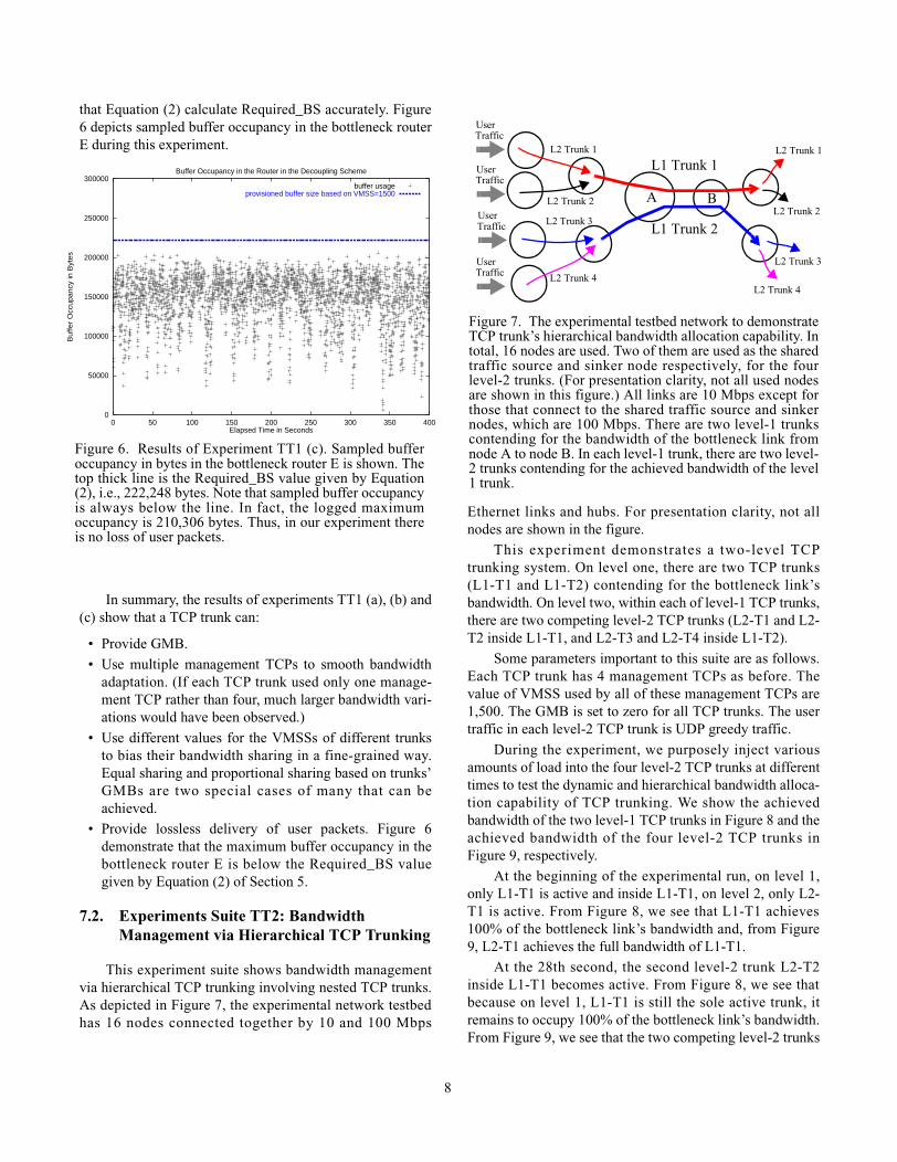
This experiment suite shows bandwidth managementvia hierarchical TCP trunking involving nested TCP trunks.As depicted in Figure 7, the experimental network testbedhas 16 nodes connected together by 10 and 100 Mbps
Ethernet links and hubs. For presentation clarity, not allnodes are shown in the figure.
This experiment demonstrates a two-level TCPtrunking system. On level one, there are two TCP trunks(L1-T1 and L1-T2) contending for the bottleneck link’sbandwidth. On level two, within each of level-1 TCP trunks,there are two competing level-2 TCP trunks (L2-T1 and L2-T2 inside L1-T1, and L2-T3 and L2-T4 inside L1-T2).
Some parameters important to this suite are as follows.Each TCP trunk has 4 management TCPs as before. Thevalue of VMSS used by all of these management TCPs are1,500. The GMB is set to zero for all TCP trunks. The usertraffic in each level-2 TCP trunk is UDP greedy traffic.
During the experiment, we purposely inject variousamounts of load into the four level-2 TCP trunks at differenttimes to test the dynamic and hierarchical bandwidth alloca-tion capability of TCP trunking. We show the achievedbandwidth of the two level-1 TCP trunks in Figure 8 and theachieved bandwidth of the four level-2 TCP trunks inFigure 9, respectively.
At the beginning of the experimental run, on level 1,only L1-T1 is active and inside L1-T1, on level 2, only L2-T1 is active. From Figure 8, we see that L1-T1 achieves100% of the bottleneck link’s bandwidth and, from Figure9, L2-T1 achieves the full bandwidth of L1-T1.
At the 28th second, the second level-2 trunk L2-T2inside L1-T1 becomes active. From Figure 8, we see thatbecause on level 1, L1-T1 is still the sole active trunk, itremains to occupy 100% of the bottleneck link’s bandwidth.From Figure 9, we see that the two competing level-2 trunks
0
50000
100000
150000
200000
250000
300000
0 50 100 150 200 250 300 350 400
Buf
fer
Occ
upan
cy in
Byt
es
Elapsed Time in Seconds
Buffer Occupancy in the Router in the Decoupling Scheme
buffer usageprovisioned buffer size based on VMSS=1500
Figure 6. Results of Experiment TT1 (c). Sampled bufferoccupancy in bytes in the bottleneck router E is shown. Thetop thick line is the Required_BS value given by Equation(2), i.e., 222,248 bytes. Note that sampled buffer occupancyis always below the line. In fact, the logged maximumoccupancy is 210,306 bytes. Thus, in our experiment thereis no loss of user packets.
L1 Trunk 2
Figure 7. The experimental testbed network to demonstrateTCP trunk’s hierarchical bandwidth allocation capability. Intotal, 16 nodes are used. Two of them are used as the sharedtraffic source and sinker node respectively, for the fourlevel-2 trunks. (For presentation clarity, not all used nodesare shown in this figure.) All links are 10 Mbps except forthose that connect to the shared traffic source and sinkernodes, which are 100 Mbps. There are two level-1 trunkscontending for the bandwidth of the bottleneck link fromnode A to node B. In each level-1 trunk, there are two level-2 trunks contending for the achieved bandwidth of the level1 trunk.
L1 Trunk 1L2 Trunk 1
L2 Trunk 2
L2 Trunk 3
L2 Trunk 4
L2 Trunk 1
L2 Trunk 2
L2 Trunk 3
L2 Trunk 4
UserTraffic
UserTraffic
UserTraffic
UserTraffic
A B
8

(L2-T1 and L2-T2) inside L1-T1 share the bandwidth ofL1-T1 fairly.
At the 58th second, the level-2 trunk L2-T3 becomesactive. This makes the level-1 L1-T2 that contains L2-T3become active as well. From Figure 8, we see that the twocompeting active level-1 trunks (L1-T1 and L1-T2) sharethe bandwidth fairly. From Figure 9, we see that the twolevel-2 trunks (L2-T1 and L2-T2) inside L1-T1 share thebandwidth of L1-T1 fairly, and the sole level-2 trunk (L2-T3) inside L1-T2 uses the whole bandwidth of L1-T2.
At the 90th second, the level-2 trunk L2-T4 becomesactive. It starts to compete with L2-T3 for the bandwidth ofL1-T2. From Figure 9, we see that now L2-T3 and L2-T4fairly share the bandwidth of L1-T2. From Figure 8, we seethat L1-T1 and L1-T2 still fairly share the bottleneck link’sbandwidth on level 1. The introduction of a new activelevel-2 trunk in L1-T2 does not affect the bandwidth alloca-tion on level 1 between L1-T1 and L1-T2.
In summary, the above experimental results show thatTCP trunking can dynamically allocate bandwidth fornested TCP trunks.
7.3. Experiments Suite TT3: ProtectingInteractive Web Users
This suite of experimental results, depicted in Figure10, shows that TCP trunking can provide protection forinteractive Web users when competing against long-livedgreedy TCP connections. That is, short Web transfers canreceive approximately their fair share of the available band-width and avoid unnecessary time-outs. In these experi-ments, each run lasts 10 minutes or longer.
Consider the configuration depicted in Figure 10 (b).On the middle router where traffic merges, there are many
short-lived Web transfers coming from an input port (a site)to compete for an output port's bandwidth (1200 KB/sec)with other long-lived greedy ftp transfers that come fromtwo other input ports (sites).
Figure 10 (a) shows that when there are only short-lived, 8KB Web transfers in the network, the offered loaduses 453 KB/sec bandwidth. (The offered load is limited to453 KB/sec, because TCP windows for these Web transfersnever ramp up significantly due to the small 8KB size of thetransfers.) The request-response delays for these short-livedWeb transfers are small and predictable. The mean delay,maximum delay, and the standard deviation of the delaysare 353 ms, 1,270 ms, and 82 ms, respectively.
Figure 10 (b) shows that after long-lived greedy ftptransfers (“put file” sessions) are introduced into thenetwork, the short-lived Web transfers can only achieve 122KB/sec bandwidth in aggregate, which is much smaller thantheir fare share (1200/3 KB/sec). The mean delay,maximum delay, and the standard deviation of the delaysincrease greatly and become 1,170 ms, 11,170 ms, and1,161 ms, respectively. This means that the short-lived Webtransfers are very fragile (the reasons are discussed in [12])and encounter more time-outs than before. As a result, theycannot receive their fair share of the bandwidth of thebottleneck link when competing with long-lived greedy ftptransfers.
Figure 10 (c) shows that when a TCP trunk is used foreach site to carry the site's aggregate traffic, the bandwidthused by the short-lived Web transfers increases to 238 KB/sec. The mean delay, maximum delay, and the standarddeviation of the delays also improve greatly and become613 ms, 2,779 ms, and 274 ms, respectively.
Figure 8. Achieved bandwidth of the two level-1 trunks.
0
200
400
600
800
1000
1200
1400
20 40 60 80 100 120
Ach
ieve
d T
hrou
ghpu
t (K
B/s
ec)
Elapsed Time in Seconds
Level 1 Trunk 1Level 1 Trunk 2
L1-T1
L1-T2
Figure 9. Achieved bandwidth of the four level-2 TCPtrunks.
0
200
400
600
800
1000
1200
20 40 60 80 100 120
Elapsed Time in Seconds
Level 2 Trunk 1 inside Level 1 Trunk 1Level 2 Trunk 2 inside Level 1 Trunk 1Level 2 Trunk 3 inside Level 1 Trunk 2Level 2 Trunk 4 inside Level 1 Trunk 2L2-T1
L2-T2
L2-T3
L2-T4
9

7.4. Experiments Suite TT4: Protecting TCPFlows against UDP Flows over a Ring
This experiments suite shows that TCP trunks can helpprotect TCP flows against UDP flows. We use a ring testbednetwork of Figure 11, on which TCP connections will expe-rience multiple bottlenecks. As depicted in the figure, thetestbed has five routers on the ring, five edge routers wherethe senders and receivers of TCP trunks are implemented,and five hosts where senders and receivers of user TCP orUDP flows reside.
All the experiment runs last 300 seconds. We config-ured each of these routers to have a buffer of 50 packets,and each trunk sender a buffer of 100 packets. All the linkson the testbed have negligibly small propagation delays.The maximum window size for user TCP flows is 64KB.
In case (a) of Figure 12, there are only small TCP trans-fers with no competing traffic. In case (b), there is acompeting UDP flow from node 3 to node 4. This is an on-off UDP flow with each on or off period lasting 10ms. Thesource of the UDP flow will try to send as many 1024-byteUDP packets as possible during each on period. In case (c)there are two trunks: one trunk carries small file transfersfrom node 2 to node 1, and the other carries UDP trafficfrom node 3 to node 4. In case (d), there are two additionalgreedy long-lived TCP transfers from node 4 to node 5, andfrom node 5 to node 2.
Table 1 shows average throughput and delay statisticsfor the small file transfers from node 2 to node 1. From theexperimental results, we see that these small transfers sufferwhen they compete with UDP traffic. Their throughput isreduced from about 380 KByte/s to about 53 KByte/s. Theirmean, standard deviation, and maximum delay areincreased. With TCP trunks, the situat ion is muchimproved. The throughput for small transfers increases toabout 270 and 252 KByte/s for case (c) or (d), respectively.The delay statistics are also improved.
10 Web servers send8KB Web pages
50 Pkts
453 KB/s[mean: 353 ms, std: 82 ms]
Link_BW
max: 1,270 ms
=1200 KB/s
Figure 10. TCP Trunking Experiments Suite TT3. Web sitethroughput: (a) under no competing ftp traffic and (b) undercompeting ftp traffic. (c) Web side performance for load (b)when three TCP trunks, one for each site, are used.
10 Web servers send8KB Web pages
122 KB/s[mean: 1,170 ms, std: 1,161 ms]
Link_BW
max: 11,170 ms
=1200 KB/s
5 greedyftp “put file”
5 greedyftp “put file”
10 Web servers send8KB Web pages
238 KB/s[mean: 613 ms, std: 274 ms]
Link_BW
max: 2,779 ms
=1200 KB/s
(a)
(b)
(c)
TCPTrunk
sessions
sessions
5 greedyftp “put file”sessions
5 greedyftp “put file”sessions
RTT=10 ms
Figure 11. A ring testbed network for TCP trunking exper-iments TT4. The testbed consists of five hosts, five edgerouters which are used as TCP trunk senders or receivers,and five routers on the ring.
Host
TCP TrunkSender or Receiver
Router
10

8. Related Work
The approach of using management packets for TCPtrunks is similar to that of using resource management cells[14] for ATM ABR virtual circuits. These managementpackets or cells are independent of user traffic in the sensethat they are injected into and removed from the networkwithout modifying the user packets and they do not have tobe aware of the user data protocols.
Being the dominant congestion control protocol used inthe current Internet, TCP has received much attention from
many researchers (e.g., [15, 16, 17]). The TCP trunkingapproach can incorporate advanced TCP congestion controlresults when they become available.
Explicit congestion notification methods [18, 19, 20]such as ECN mark user packets to indicate congestion inrouters. These marked packets will then signal their sourceto reduce their sending rates. Although ECN methodspotentially can provide the “lossless” property for userpackets, there are some problems with them. Markingpackets in routers alone does not automatically achieve the“lossless” property. That is, traffic sources must also reducetheir sending rates when receiving marked packets. It is notclear how a traffic source’s congestion control shouldrespond to these marked packets to make the traffic TCP-friendly. Marked packets may be dropped or remarked whenthey are on their way to the destination or back to thesource. These problems are difficult and require muchfurther investigations. In contrast, the TCP trunkingapproach uses the well-established TCP congestion controlto regulate the sending rate of a traffic flow, and is 100%TCP-friendly.
9. Conclusions
TCP trunking is a novel way of applying TCP conges-tion control to bandwidth management of aggregate traffic.It appears to be one of the few techniques that could providedynamic congestion control for traffic aggregates. As theInternet usage continues to scale up, traffic aggregationbecomes increasingly important, so does their bandwidthmanagement tools such as TCP trunking.
Traditionally, TCP has been the dominant protocol thatprovides dynamic congestion control for individual flowsbetween end hosts. The TCP trunking work of this paper hasshown that TCP is also suited in providing dynamic conges-tion control for aggregate flows between network nodes.
References
[1] H.T. Kung and S.Y. Wang “TCP Trunking: Design, Imple-mentation, and Performance”, IEEE ICNP'99, Toronto,Canada, 1999.
[2] S. Y. Wang, “Decoupling Control from Data for TCPCongestion Control,” Ph.D. Thesis, Harvard University,September 1999. (available at http://www.eecs.harvard.edu/networking/decoupling.html)
[3] Classless Inter-Domain Routing (CIDR): an AddressAssignment and Aggregation Strategy, RFC1519, 1993
[4] K, Nichols, V. Jacobson, L. Zhang, “A Two-bit Differenti-ated Services Architecture for the Internet,” RFC 2638, July1999.
[5] S. Blake et al., “An Architecture for DifferentiatedServices,” RFC 2475, December 1998.
[6] R. Morris, “TCP Behavior with Many Flows,” IEEEICNP’97, Atlanta USA, 1997.
CaseAverage
Throughput(KByte/s)
Delay Statistics (ms)for 8 K transfers
Mean SD Max
(a) 380.05 451.5 147.9 1336
(b) 53.21 2541.1 4021.7 13053
(c) 270.45 507.9 136.5 1921
(d) 252.65 663.9 166.9 1892
Table 1: Performance results of TCP Trunking ExperimentsSuite TT4 (b) of Figure 12. Average throughputs and delaysfor small TCP transfers from node 2 to node 1 are muchimproved when TCP trunks are used.
(a) (b)
(c) (d)
Figure 12. TCP Trunking Experiments Suite TT4: smallTCP transfers compete with UDP flows. In (d), two otherexternal traffic flows are introduced to create the multi-bottleneck configuration. Performance results are summa-rized in Table 1.
SmallTCPTransfers
UDPFlows
Trunk1
Trunk2 Trunk2
1
2
34
5
1
2
34
5
1
2
34
5
1
2
34
5
Trunk1
11

[7] D. O. Awduche, J. Malcolm, J. Agogbua, M. O’Dell and J.McManus, “Requirements for Traffic Engineering OverMPLS,” RFC 2702, September 1999.
[8] R. Callon et al., “A Framework for Multiprotocol LabelSwitching,” Internet draft, September 1999.
[9] The TCP-Friendly Website, http://www.psc.edu/networking/tcp_friendly.html, 1999.
[10] S. Y. Wang and H.T. Kung, “A Simple Methodology forConstructing an Extensible and High-Fidelity TCP/IPNetwork Simulator,” INFOCOM’99, New York, USA, 1999.
[11] FreeBSD web site at www.freebsd.org.
[12] D. Lin, and H. T. Kung, “TCP Fast Recovery Strategies:Analysis and Improvements,” INFOCOM'98, San Francisco,USA, 1998.
[13] S. Floyd and V. Jacobson, “Random Early Detection Gate-ways for Congestion Avoidance,” Transactions onNetworking, Vol. 1, No. 4, August 1993.
[14] ATM Forum Traffic Management Specifications 4.0.
[15] Francois Baccelli and Dohy Hong, “TCP is Max-PlusLinear,” ACM SIGCOMM’2000, Stockholm, Sweden, 2000.
[16] Eitan Altman, Kostia Avrachenkov, Chadi Barakat, “AStochastic Model of TCP/IP with Stationary RandomLosses,” ACM SIGCOMM’2000, Stockholm, Sweden,2000.
[17] Jitendra Padhye, Victor Firoiu, Don Towsley, and JimKurose, “Modeling TCP Throughput: A Simple Model andits Empirical Validation,” ACM SIGCOMM’98, Vancouver,Canada, 1998.
[18] S. Floyd, “TCP and Explicit Congestion Notification,” ACMComputer Communication Review, V. 24 N. 5, October1994, p. 10-23.
[19] K. K. Ramakrishnan, and S. Floyd, “A Proposal to addExplicit Congestion Notification (ECN) to IP,” RFC 2481,January 1999.
[20] K. K. Ramakrishnan and R. Jain, “A Binary FeedbackScheme for Congestion Avoidance in Computer Networkswith Connectionless Network Layer,” ACM Transactions onComputer Systems 8(2): 158-181, May 1990.
12