tcp/iptcp/ip dr. clincylecture1 ch3: underlying technologies (3 of 3) exam 1 study guide and...
TRANSCRIPT
Dr. Clincy Lecture 1
TCP
/
I
P
Ch3: Underlying Technologies (3 of 3)
Exam 1 Study Guide and Instructions - scheduled for Feb 11th (2-hour exam between 3:30pm-7pm) – cover chapters 1-3, lectures 1-5 - open book - M/C, FIB, Short Problems, Problems - Can use a calculator – no laptop and no PDA
Practice test posted on Web-CT by Tuesday next weekProject 1 Part 2 posted by Monday
Lecture #5

Dr. Clincy Lecture 2
TCP
/
I
P
Internet – Underlying Technologies• Internet is comprised of LANs, Point-to-Point WANs and Switched
WANs
• We have covered LANS: Ethernet, Token Ring (not in book), Wireless and FDDI Ring (not in book)
• We have covered Pt-to-Pt WANs: Telephony Modem, DSL, Cable/Modem, T-Lines and SONET
• We will cover Switched WANs: X.25, Frame Relay and ATM

Dr. Clincy Lecture 3
TCP
/
I
P
SWITCHED WANS• Switched WAN - a mesh of point-to-point networks connected via
switches
• Unlike LANS – multiple paths are needed between locations
• Unlike LANS – no direct relationship between Tx and Rx
• Paths are determined upfront and theses paths are used to send and receive (multiple paths for reliability and restoration) – recall that LANS uses Tx/Rx addresses to make the connection
• Uses Virtual Circuit concept
• 3 well known Switch WANs: X.25, Frame Relay and ATM
Dr. Clincy Lecture 4
TCP
/
I
P
X.25• Developed in 1970 – the first switch WAN – becoming
more and more obsolete
• X.25 standard describes all of the functions necessary for communicating with a packet switching network
• Divided into 3 levels:
• (1) physical level – describes the actual interfaces
• (2) frame level – describes the error detection and correction
• (3) Packet level – provides network-level addressing(constant BW efficiency problem – but it worked)
Because X.25 was developed before the Internet, the IP packets are encapsulated in the X.25 packet when you have an IP network on each side of a X.25 backbone
Dr. Clincy Lecture 5
TCP
/
I
P
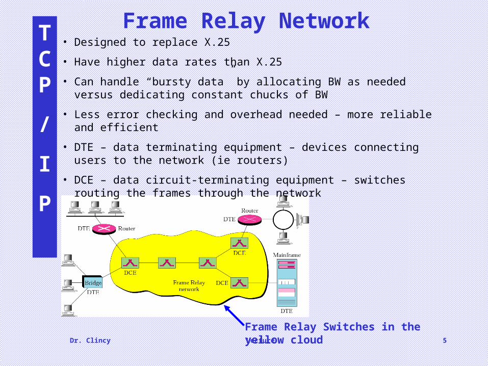
Frame Relay Network• Designed to replace X.25
• Have higher data rates than X.25
• Can handle “bursty data” by allocating BW as needed versus dedicating constant chucks of BW
• Less error checking and overhead needed – more reliable and efficient
• DTE – data terminating equipment – devices connecting users to the network (ie routers)
• DCE – data circuit-terminating equipment – switches routing the frames through the network
Frame Relay Switches in the yellow cloud
Dr. Clincy Lecture 6
TCP
/
I
P
Switched WANs - ATM• ATM – Asynchronous Transfer Mode – is a cell relay protocol
• Objectives of ATM (upfront initiative):
1. Make better use of high data rate transmission (ie. fiber optics)
2. WAN between various types of packet-switch networks that will not drive a change in the packet-switch networks
3. Must be inexpensive (no barrier to use) – want it to be the international backbone
4. Must be able to support the existing network hierarchies – local loops, long-distance carriers, etc..)
5. Must be connection-oriented (high reliability)
6. Make more hardware oriented versus software oriented in speeding up rates (explain this – circuit vs software)
• Cell – small unit of data of fixed size – basic unit of data exchange
• Different types of data is loaded into identical cells
• Cells are multiplexed with other cells and routed
• By having a static size, the delivery is more predictable and uniform
Dr. Clincy Lecture 7
TCP
/
I
P
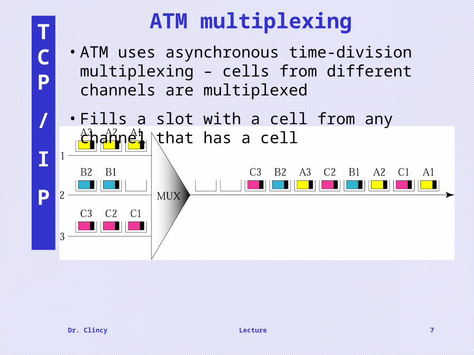
ATM multiplexing• ATM uses asynchronous time-division multiplexing –
cells from different channels are multiplexed
• Fills a slot with a cell from any channel that has a cell

Dr. Clincy Lecture 8
TCP
/
I
P
Architecture of an ATM network
• User access devices (called end points) are through a user-to-network interface (UNI) to switches in the network
• The switches are connected through network-to-network interfaces (NNI)

Dr. Clincy Lecture 9
TCP
/
I
P
Virtual circuits• Connections between points are accomplished using transmission
paths (TP), virtual paths (VP) and virtual circuits (VC).
• TP – all physical connections between two points
• VP – set of connections (a subset of TP) (ie. Highway)
• VC – all cells belonging to a single message follow the same VC and remain in original order until reaching Rx (ie. Lane)
• The virtual connection is defined by the VP and VC identifiers

Dr. Clincy Lecture 10
TCP
/
I
P
An ATM cell

Dr. Clincy Lecture 11
TCP
/
I
P
ATM layers• ATM Standard defines 3 layers: Application Adaptation Layer, ATM Layer and Physical
Layer
• Application Adaptation Layer – facilitates communications between ATM networks and other Packet-Switched Networks by taking the packets and fitting them into fixed-sized CELLS.
• At the Rx, cells are re-assembled back into packets
• Keep in mind that any type of transmission signal can be packaged into an ATM cell: data, voice, audio and video - makes ATM very powerful
Application Adaptation Layer is divided into 4 parts:
• AAL1- handles the constant bit rate cases (ie. voice, real-video)
• AAL2- handles variable bit rate cases (ie. compressed voice, non-real-time video, data)
• AAL3/4 – handles connection-oriented data services (ie VoIP)
• AAL5 – handles connectionless-oriented protocols (ie. TCP/IP)
Dr. Clincy Lecture 12
TCP
/
I
P
ATM layers
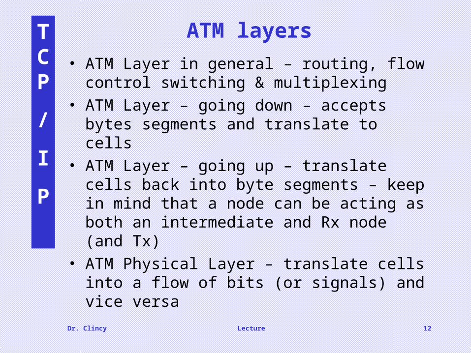
• ATM Layer in general – routing, flow control switching & multiplexing
• ATM Layer – going down – accepts bytes segments and translate to cells
• ATM Layer – going up – translate cells back into byte segments – keep in mind that a node can be acting as both an intermediate and Rx node (and Tx)
• ATM Physical Layer – translate cells into a flow of bits (or signals) and vice versa

Dr. Clincy Lecture 13
TCP
/
I
P
ATM LAN architecture• ATM LAN speeds: 155 Mbps and 622 Mbps
• 3 design approaches: (1) pure ATM LAN, (2) legacy ATM LAN and (3) combo of (2) and (3)
• Pure ATM LAN: ATM switch is used to connect the stations in a LAN (uses VPI/VCI versus destination/source addresses)

Dr. Clincy Lecture 14
TCP
/
I
P
Legacy ATM LAN architecture
• Use an ATM LAN as a backbone – frames staying with in a certain network need not be converted
• Frames needing to cross to another LAN must be converted and ride the ATM LAN

Dr. Clincy Lecture 15
TCP
/
I
P
Mixed ATM LAN Architecture

Dr. Clincy Lecture 16
TCP
/
I
P
Internet – Underlying Technologies• Recall that the Internet is comprised of LANs, Point-to-Point WANs and
Switched WANs• We covered LANS: Ethernet, Token Ring, Wireless and FDDI Ring• We covered Switched WANs: X.25, Frame Relay and ATM• We covered Pt-to-Pt WANs: Telephony Modem, DSL, Cable/Modem, T-
Lines and SONET
How are these networks connected ?
Dr. Clincy Lecture 17
TCP
/
I
P
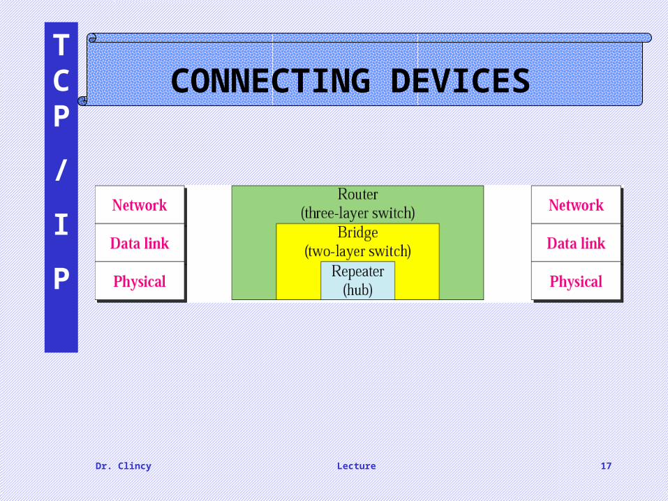
CONNECTING DEVICES
Dr. Clincy Lecture 18
TCP
/
I
P
Repeater
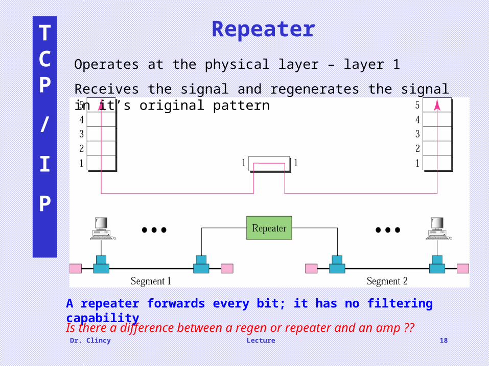
Operates at the physical layer – layer 1
Receives the signal and regenerates the signal in it’s original pattern
Is there a difference between a regen or repeater and an amp ??
A repeater forwards every bit; it has no filtering capability
Dr. Clincy Lecture 19
TCP
/
I
P
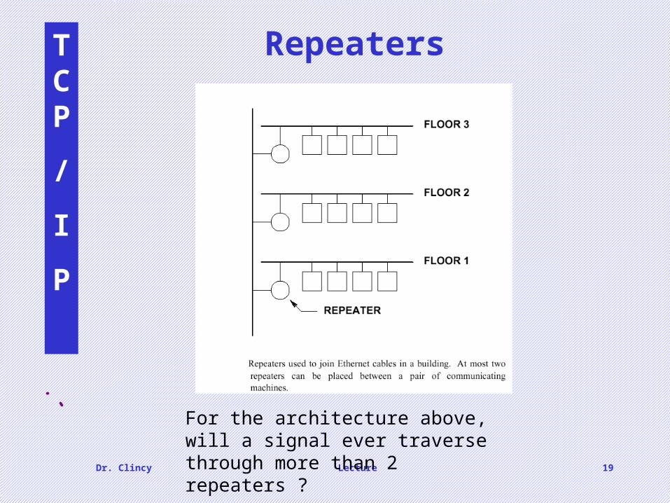
Repeaters
d
For the architecture above, will a signal ever traverse through more than 2 repeaters ?

Dr. Clincy Lecture 20
TCP
/
I
P
HubsHub – multi-port repeater
Typically used to create a physical star topology
Also used to create multiple levels of hierarchy
For bus technology type networks, hubs can be used to increase the collision domain

Dr. Clincy Lecture 21
TCP
/
I
P
Bridge• Operates at both the physical and data link layers
• At layer 1, it regenerates the signal. At layer 2, it checks the Tx/Rx physical address (using a bridge table)
• Example Below:
• If packet arrives to bridge-interface #1 for either of the 71….. stations, the packet is dropped because the 71…. Stations will see the packet
• If packet arrives to bridge-interface #2 for either of the 71….. stations, the packet is forwarded to bridge-interface #1
With such an approach, the “bridged” network segments will acted as a single larger network
What is a “smart” bridge ??
Dr. Clincy Lecture 22
TCP
/
I
P
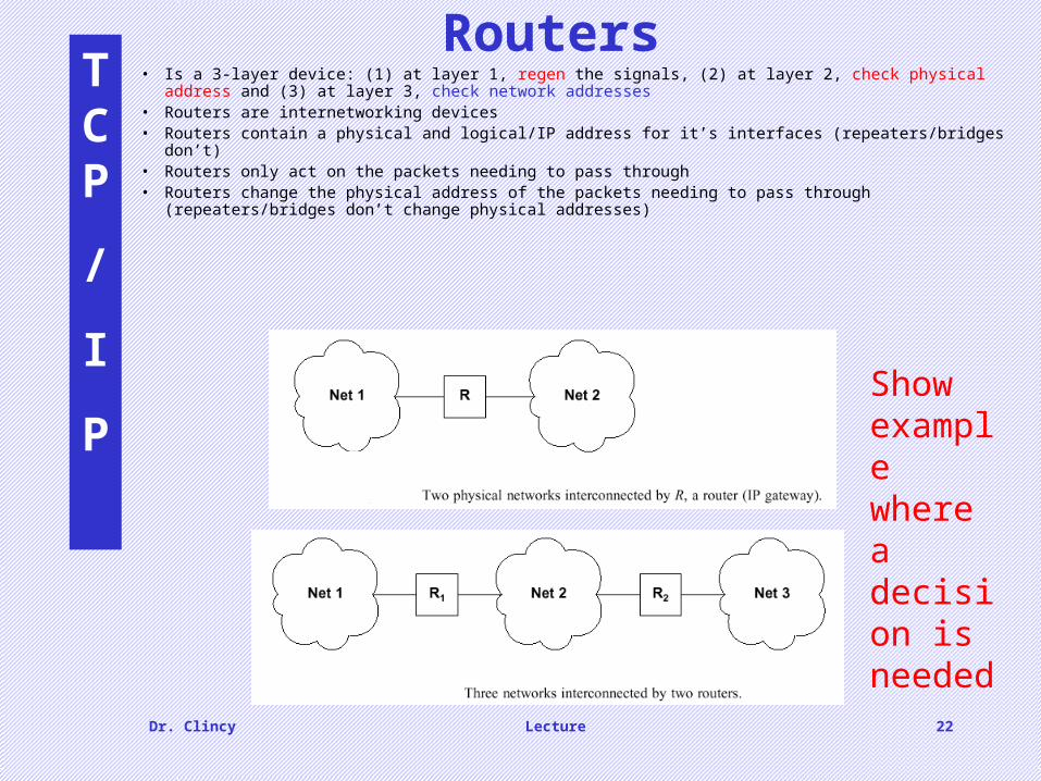
Routers• Is a 3-layer device: (1) at layer 1, regen the signals, (2) at layer 2, check physical address and (3) at layer 3,
check network addresses• Routers are internetworking devices• Routers contain a physical and logical/IP address for it’s interfaces (repeaters/bridges don’t)• Routers only act on the packets needing to pass through• Routers change the physical address of the packets needing to pass through (repeaters/bridges don’t change
physical addresses)
d
d
Show example where a decision is needed
Dr. Clincy Lecture 23
TCP
/
I
P
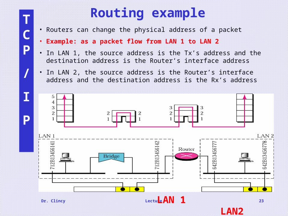
Routing example
LAN 1 LAN2
• Routers can change the physical address of a packet
• Example: as a packet flow from LAN 1 to LAN 2
• In LAN 1, the source address is the Tx’s address and the destination address is the Router’s interface address
• In LAN 2, the source address is the Router’s interface address and the destination address is the Rx’s address
Dr. Clincy Lecture 24
TCP
/
I
P
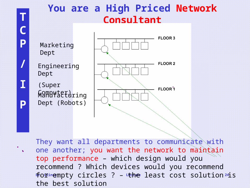
You are a High Priced Network Consultant
dThey want all departments to communicate with one another; you want the network to maintain top performance – which design would you recommend ? Which devices would you recommend for empty circles ? – the least cost solution is the best solution
Marketing Dept
Engineering Dept
(Super Computer)
Manufacturing Dept (Robots)

Dr. Clincy Lecture 25
TCP
/
I
P
For entertainment purposes – and if time permits….
• If time permits, illustrate how the US Postal System is very similar to how networking works
• Will help students better understand (versus memorize) networking
Lower Layers – getting the signal from one place to the next
Upper Layers – creating and interpreting the signal, data or info
US Postal System Analogy