td-quickcompress installation instructions
TRANSCRIPT

8/6/2019 TD-QuickCompress Installation Instructions
http://slidepdf.com/reader/full/td-quickcompress-installation-instructions 1/11
117
© 2003, AFL Telecommunications, all rights reserved. Revision 0, 11.28.05Specifications are subject to change without notice.
Installation Instructions for Non-Adjustable Quick CompressDead Ends for ACSR Conductors
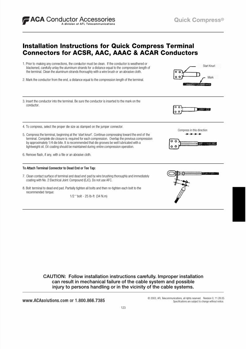
1. Prior to making any connections, the conductor must be wire brushed. If the conductor is weatheredor blackened, carefully unlay the aluminum strands for a distance equal to the compression length ofthe dead end barrel. Clean the aluminum strands thoroughly with a wire brush or an abrasive cloth.Straighten several feet of conductor removing set caused by reel.
2. Mark the conductor from the end, a distance equal to the length of compression barrel.
3. Cut the aluminum strands back a distance equal to the length of the core grip plus 1/4 inch (6mm).Do not nick the steel strands. File burrs as necessary for ease of insertion.
4. Insert the steel core into the core grip. Do not twist the core grip while inserting core wire.
5. Insert the core grip and conductor into the compression barrel. Be sure the conductor is insertedbeyond the mark on the conductor.
6. To compress the aluminum barrel, select the proper die size as stamped on the barrel.
7. The dead end will bow during compression unless care is taken to have 15 feet (4.5 m) of theconductor supported straight out from the end of the dead end. The weight of the conductor shouldnot hang unsupported when compressing.
8. Make the initial compression at the “start knurl” and continue making compressions to the end ofthe dead end body. Complete die closure is required for each compression. Overlap the previouscompression by approximately 1/4 die bite. It is recommended that die grooves be well lubricatedwith a lightweight oil. Oil coating should be maintained during entire compression operation.
9. Remove flash, if any, with a file or an abrasive cloth.
Start Knurl
Mark
Core Grip
Compress in this direction
CAUTION: Follow installation instructions carefully. Improper installationcan result in mechanical failure of the cable system and possibleinjury to persons handling or in the vicinity of the cable systems.

8/6/2019 TD-QuickCompress Installation Instructions
http://slidepdf.com/reader/full/td-quickcompress-installation-instructions 2/11
118
© 2003, AFL Telecommunications, all rights reserved. Revision 0, 11.28.05Specifications are subject to change without notice.
I N
S
T A
L L A T I O
N
1. Prior to making any connections, the conductor must be wire brushed. If the conductor isweathered or blackened, carefully unlay the aluminum strands for a distance equal to thecompression length of the dead end barrel. Clean the aluminum strands thoroughly with a wirebrush or an abrasive cloth. Straighten several feet of conductor removing set caused by reel.
2. Mark the conductor from the end, a distance equal to the length of compression barrel.
3. File burrs or sharp edges off the aluminum strands as necessary for ease of insertion.
4. Insert the conductor into the compression barrel. Be sure the conductor is inserted beyond themark on the conductor.
5. To compress the aluminum barrel, select the proper die size as stamped on the barrel.
6. The dead end will bow during compression unless care is taken to have 15 feet (4.5 m) of theconductor supported straight out from the end of the dead end. The weight of the conductorshould not hang unsupported when compressing.
7. Make the initial compression at the “start knurl” and continue making compressions to the end ofthe dead end body. Complete die closure is required for each compression. Overlap the previouscompression by approximately 1/4 die bite. It is recommended that die grooves be well lubricatedwith a lightweight oil. Oil coating should be maintained during entire compression operation.
8. Remove flash, if any, with a file or an abrasive cloth.
Installation Instructions for Non-Adjustable Quick CompressDead Ends for AAC, AAAC & ACAR Conductors
1. To install, follow steps 1-9 on previous page for ACSR or 1-8 above for AAC, AAACand ACAR.
To Adjust Dead Ends
2. Loosen rear nut jam.
3. Rotate clevis or eye for proper sag.
4. Tighten rear jam nut.
Installation Instructions for Adjustable Quick Compress DeadEnds for ACSR, AAC, AAAC & ACAR Conductors
Start Knurl
Mark
Compress in this direction
Rear Jam NutFront Nut Jam
Rear Jam NutFront Nut Jam
CAUTION: Follow installation instructions carefully. Improper installationcan result in mechanical failure of the cable system and possibleinjury to persons handling or in the vicinity of the cable systems.
8/6/2019 TD-QuickCompress Installation Instructions
http://slidepdf.com/reader/full/td-quickcompress-installation-instructions 3/11
119
© 2003, AFL Telecommunications, all rights reserved. Revision 0, 11.28.05Specifications are subject to change without notice.
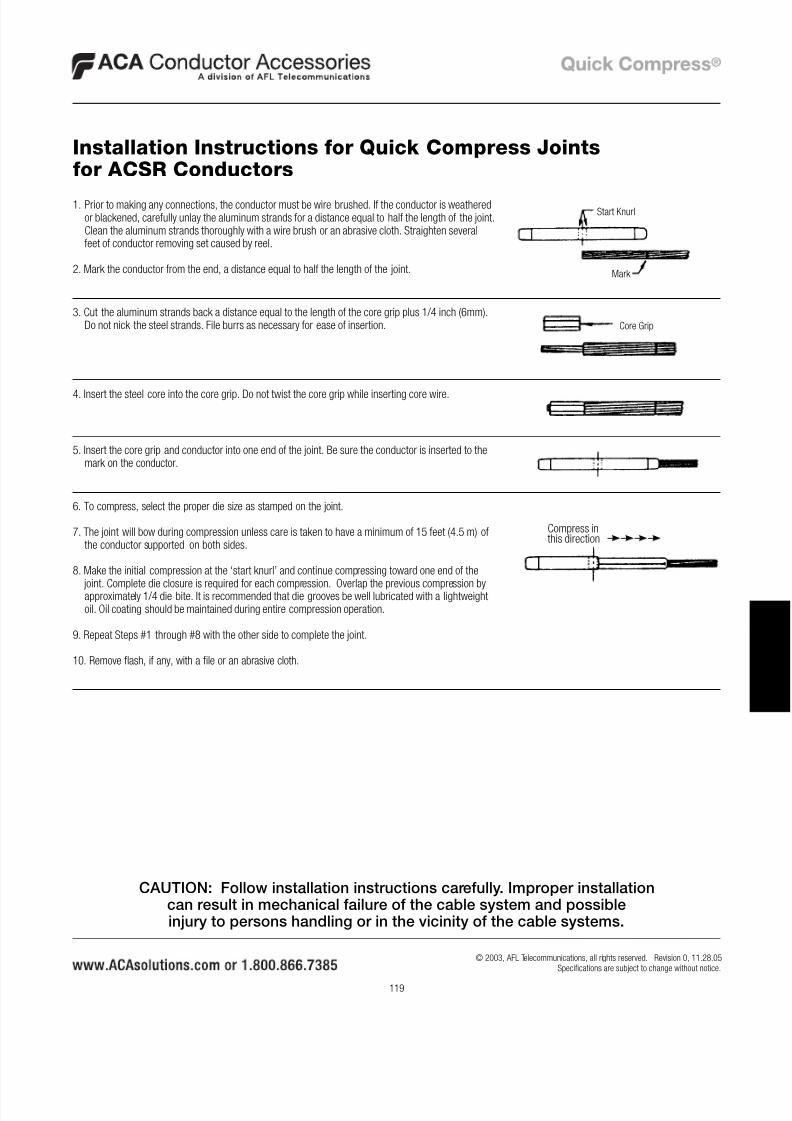
1. Prior to making any connections, the conductor must be wire brushed. If the conductor is weatheredor blackened, carefully unlay the aluminum strands for a distance equal to half the length of the joint.Clean the aluminum strands thoroughly with a wire brush or an abrasive cloth. Straighten severalfeet of conductor removing set caused by reel.
2. Mark the conductor from the end, a distance equal to half the length of the joint.
3. Cut the aluminum strands back a distance equal to the length of the core grip plus 1/4 inch (6mm).Do not nick the steel strands. File burrs as necessary for ease of insertion.
4. Insert the steel core into the core grip. Do not twist the core grip while inserting core wire.
5. Insert the core grip and conductor into one end of the joint. Be sure the conductor is inserted to themark on the conductor.
6. To compress, select the proper die size as stamped on the joint.
7. The joint will bow during compression unless care is taken to have a minimum of 15 feet (4.5 m) ofthe conductor supported on both sides.
8. Make the initial compression at the ‘start knurl’ and continue compressing toward one end of the
joint. Complete die closure is required for each compression. Overlap the previous compression byapproximately 1/4 die bite. It is recommended that die grooves be well lubricated with a lightweightoil. Oil coating should be maintained during entire compression operation.
9. Repeat Steps #1 through #8 with the other side to complete the joint.
10. Remove flash, if any, with a file or an abrasive cloth.
Installation Instructions for Quick Compress Jointsfor ACSR Conductors
Start Knurl
Mark
Core Grip
Compress inthis direction
CAUTION: Follow installation instructions carefully. Improper installationcan result in mechanical failure of the cable system and possibleinjury to persons handling or in the vicinity of the cable systems.
8/6/2019 TD-QuickCompress Installation Instructions
http://slidepdf.com/reader/full/td-quickcompress-installation-instructions 4/11
120
© 2003, AFL Telecommunications, all rights reserved. Revision 0, 11.28.05Specifications are subject to change without notice.
I N
S
T A
L L A T I O
N
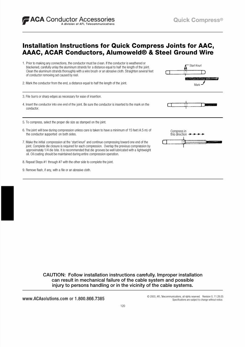
1. Prior to making any connections, the conductor must be clean. If the conductor is weathered orblackened, carefully unlay the aluminum strands for a distance equal to half the length of the joint.Clean the aluminum strands thoroughly with a wire brush or an abrasive cloth. Straighten several feetof conductor removing set caused by reel.
2. Mark the conductor from the end, a distance equal to half the length of the joint.
3. File burrs or sharp edges as necessary for ease of insertion.
4. Insert the conductor into one end of the joint. Be sure the conductor is inserted to the mark on theconductor.
5. To compress, select the proper die size as stamped on the joint.
6. The joint will bow during compression unless care is taken to have a minimum of 15 feet (4.5 m) ofthe conductor supported on both sides.
7. Make the initial compression at the ‘start knurl’ and continue compressing toward one end of the joint. Complete die closure is required for each compression. Overlap the previous compression byapproximately 1/4 die bite. It is recommended that die grooves be well lubricated with a lightweightoil. Oil coating should be maintained during entire compression operation.
8. Repeat Steps #1 through #7 with the other side to complete the joint.
9. Remove flash, if any, with a file or an abrasive cloth.
Installation Instructions for Quick Compress Joints for AAC, AAAC, ACAR Conductors, Alumoweld® & Steel Ground Wire
Start Knurl
Mark
Compress inthis direction
CAUTION: Follow installation instructions carefully. Improper installationcan result in mechanical failure of the cable system and possibleinjury to persons handling or in the vicinity of the cable systems.
8/6/2019 TD-QuickCompress Installation Instructions
http://slidepdf.com/reader/full/td-quickcompress-installation-instructions 5/11
121
© 2003, AFL Telecommunications, all rights reserved. Revision 0, 11.28.05Specifications are subject to change without notice.
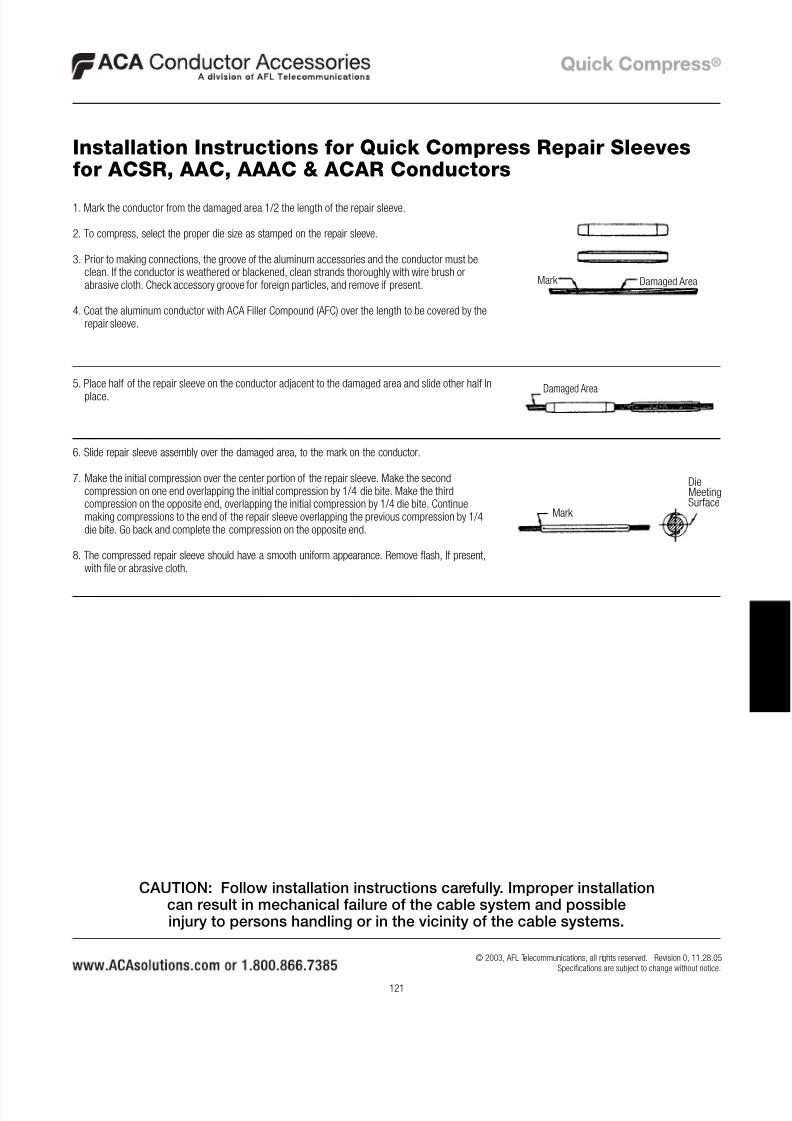
1. Mark the conductor from the damaged area 1/2 the length of the repair sleeve.
2. To compress, select the proper die size as stamped on the repair sleeve.
3. Prior to making connections, the groove of the aluminum accessories and the conductor must beclean. If the conductor is weathered or blackened, clean strands thoroughly with wire brush orabrasive cloth. Check accessory groove for foreign particles, and remove if present.
4. Coat the aluminum conductor with ACA Filler Compound (AFC) over the length to be covered by therepair sleeve.
5. Place half of the repair sleeve on the conductor adjacent to the damaged area and slide other half In
place.
6. Slide repair sleeve assembly over the damaged area, to the mark on the conductor.
7. Make the initial compression over the center portion of the repair sleeve. Make the secondcompression on one end overlapping the initial compression by 1/4 die bite. Make the thirdcompression on the opposite end, overlapping the initial compression by 1/4 die bite. Continuemaking compressions to the end of the repair sleeve overlapping the previous compression by 1/4die bite. Go back and complete the compression on the opposite end.
8. The compressed repair sleeve should have a smooth uniform appearance. Remove flash, If present,with file or abrasive cloth.
Installation Instructions for Quick Compress Repair Sleevesfor ACSR, AAC, AAAC & ACAR Conductors
Mark Damaged Area
Damaged Area
Mark
DieMeetingSurface
CAUTION: Follow installation instructions carefully. Improper installationcan result in mechanical failure of the cable system and possibleinjury to persons handling or in the vicinity of the cable systems.
8/6/2019 TD-QuickCompress Installation Instructions
http://slidepdf.com/reader/full/td-quickcompress-installation-instructions 6/11
122
© 2003, AFL Telecommunications, all rights reserved. Revision 0, 11.28.05Specifications are subject to change without notice.
I N
S
T A
L L A T I O
N
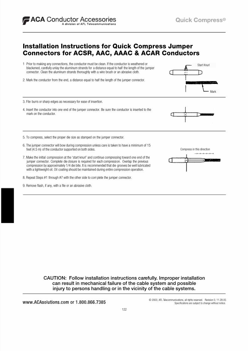
1 Prior to making any connections, the conductor must be clean. If the conductor is weathered orblackened, carefully unlay the aluminum strands for a distance equal to half the length of the jumperconnector. Clean the aluminum strands thoroughly with a wire brush or an abrasive cloth.
2. Mark the conductor from the end, a distance equal to half the length of the jumper connector.
3. File burrs or sharp edges as necessary for ease of insertion.
4. Insert the conductor into one end of the jumper connector. Be sure the conductor is inserted to themark on the conductor.
5. To compress, select the proper die size as stamped on the jumper connector.
6. The jumper connector will bow during compression unless care is taken to have a minimum of 15feet (4.5 m) of the conductor supported on both sides.
7. Make the initial compression at the ‘start knurl’ and continue compressing toward one end of the jumper connector. Complete die closure is required for each compression. Overlap the previouscompression by approximately 1/4 die bite. It is recommended that die grooves be well lubricatedwith a lightweight oil. Oil coating should be maintained during entire compression operation.
8. Repeat Steps #1 through #7 with the other side to complete the jumper connector.
9. Remove flash, if any, with a file or an abrasive cloth.
Installation Instructions for Quick Compress JumperConnectors for ACSR, AAC, AAAC & ACAR Conductors
Mark
Start Knurl
Compress in this direction
→→→→→→
CAUTION: Follow installation instructions carefully. Improper installationcan result in mechanical failure of the cable system and possibleinjury to persons handling or in the vicinity of the cable systems.
8/6/2019 TD-QuickCompress Installation Instructions
http://slidepdf.com/reader/full/td-quickcompress-installation-instructions 7/11
8/6/2019 TD-QuickCompress Installation Instructions
http://slidepdf.com/reader/full/td-quickcompress-installation-instructions 8/11
124
© 2003, AFL Telecommunications, all rights reserved. Revision 0, 11.28.05Specifications are subject to change without notice.
I N
S
T A
L L A T I O
N
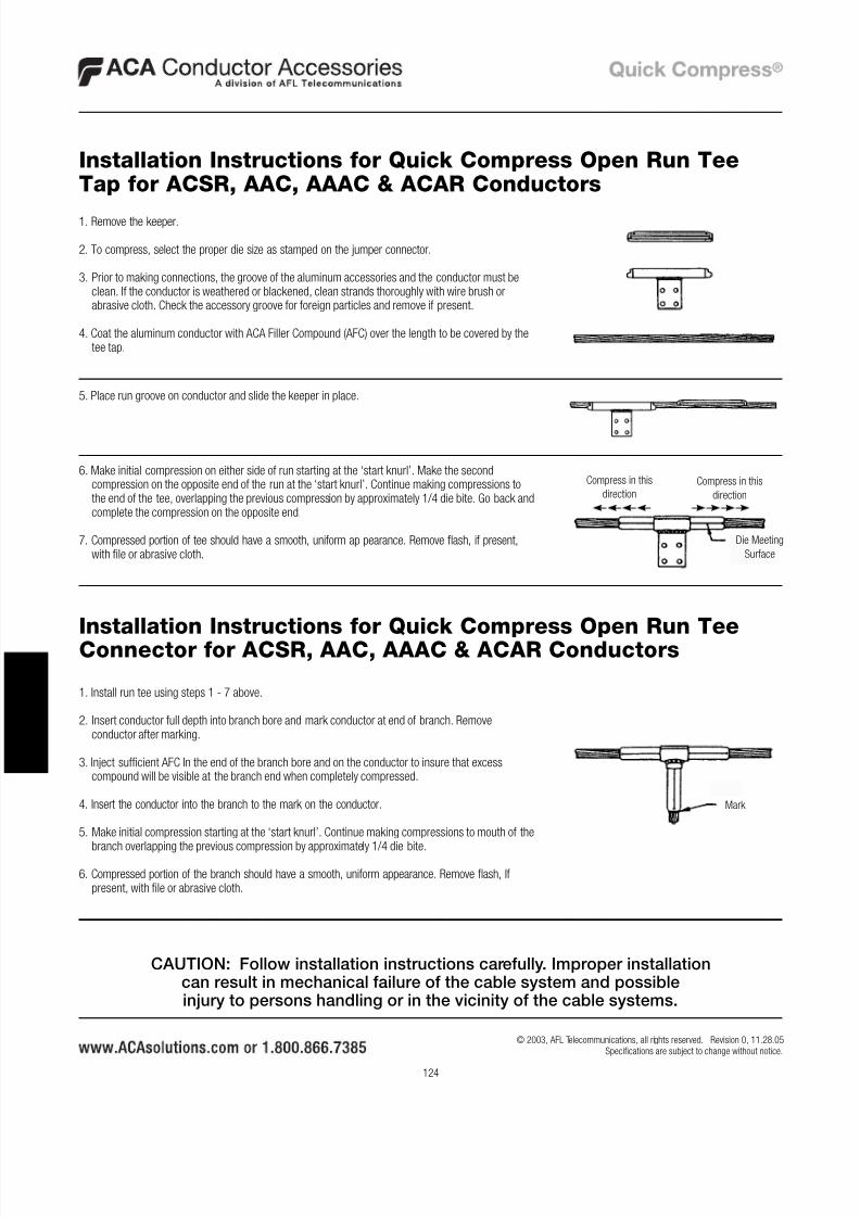
Installation Instructions for Quick Compress Open Run TeeTap for ACSR, AAC, AAAC & ACAR Conductors
1. Remove the keeper.
2. To compress, select the proper die size as stamped on the jumper connector.
3. Prior to making connections, the groove of the aluminum accessories and the conductor must beclean. If the conductor is weathered or blackened, clean strands thoroughly with wire brush orabrasive cloth. Check the accessory groove for foreign particles and remove if present.
4. Coat the aluminum conductor with ACA Filler Compound (AFC) over the length to be covered by thetee tap.
5. Place run groove on conductor and slide the keeper in place.
6. Make initial compression on either side of run starting at the ‘start knurl’. Make the secondcompression on the opposite end of the run at the ‘start knurl’. Continue making compressions tothe end of the tee, overlapping the previous compression by approximately 1/4 die bite. Go back andcomplete the compression on the opposite end.
7. Compressed portion of tee should have a smooth, uniform appearance. Remove flash, if present,with file or abrasive cloth.
1. Install run tee using steps 1 - 7 above.
2. Insert conductor full depth into branch bore and mark conductor at end of branch. Removeconductor after marking.
3. Inject sufficient AFC In the end of the branch bore and on the conductor to insure that excesscompound will be visible at the branch end when completely compressed.
4. Insert the conductor into the branch to the mark on the conductor.
5. Make initial compression starting at the ‘start knurl’. Continue making compressions to mouth of thebranch overlapping the previous compression by approximately 1/4 die bite.
6. Compressed portion of the branch should have a smooth, uniform appearance. Remove flash, Ifpresent, with file or abrasive cloth.
Die Meeting
Surface
Compress in this
direction
Compress in this
direction
Installation Instructions for Quick Compress Open Run TeeConnector for ACSR, AAC, AAAC & ACAR Conductors
Mark
CAUTION: Follow installation instructions carefully. Improper installationcan result in mechanical failure of the cable system and possibleinjury to persons handling or in the vicinity of the cable systems.
8/6/2019 TD-QuickCompress Installation Instructions
http://slidepdf.com/reader/full/td-quickcompress-installation-instructions 9/11
125
© 2003, AFL Telecommunications, all rights reserved. Revision 0, 11.28.05Specifications are subject to change without notice.
Index
ACS SeriesACSR Conductor . . . . . . . . . . . . . . . . . . . . . . . . . . . . . . 17
AAAC & ACAR Conductors . . . . . . . . . . . . . . . . . . . . . . . 81
ACSE Series for AAC Conductor. . . . . . . . . . . . . . . . . . . . . . . 53
AES Series
ACSR Conductor . . . . . . . . . . . . . . . . . . . . . . . . . . . . . . 20
AAAC & ACAR Conductor . . . . . . . . . . . . . . . . . . . . . . . 83
AESE Series for AAC Conductor . . . . . . . . . . . . . . . . . . . . . . . 55
CJ Series
ACSR Conductor . . . . . . . . . . . . . . . . . . . . . . . . . . . . . . 23
AAAC & ACAR Conductors . . . . . . . . . . . . . . . . . . . . . . . 85
CJE Series for AAC Conductor . . . . . . . . . . . . . . . . . . . . . . . . 57CJER Series for AAC Conductor . . . . . . . . . . . . . . . . . . . . . . . 59
CJR Series
ACSR Conductor . . . . . . . . . . . . . . . . . . . . . . . . . . . . . . 25
AAAC & ACAR Conductors . . . . . . . . . . . . . . . . . . . . . . . 87
Compression Joints
ACSR Conductors . . . . . . . . . . . . . . . . . . . . . . . . . . . . . 23
AAC Conductors . . . . . . . . . . . . . . . . . . . . . . . . . . . . . . 57
AAAC & ACAR Conductors . . . . . . . . . . . . . . . . . . . . . . . 85
Ground Wire . . . . . . . . . . . . . . . . . . . . . . . . . . . . . . . . 108
Conductor Information - See Reference Material
Dead Ends, CompressionSingle Tongue
ACSR Conductor . . . . . . . . . . . . . . . . . . . . . . . . . . . . 11
AAC Conductor . . . . . . . . . . . . . . . . . . . . . . . . . . . . . 49
AAAC & ACAR Conductor . . . . . . . . . . . . . . . . . . . . . . 77
Ground Wire . . . . . . . . . . . . . . . . . . . . . . . . . . . . . . 105
Double Tongue
ACSR Conductor . . . . . . . . . . . . . . . . . . . . . . . . . . . . 14
AAC Conductor . . . . . . . . . . . . . . . . . . . . . . . . . . . . . 51
AAAC & ACAR Conductor . . . . . . . . . . . . . . . . . . . . . . 79
Adjustable Clevis
ACSR Conductor . . . . . . . . . . . . . . . . . . . . . . . . . . . . 17AAC Conductor . . . . . . . . . . . . . . . . . . . . . . . . . . . . . 53
AAAC & ACAR Conductor . . . . . . . . . . . . . . . . . . . . . . 81
Adjustable Eye
ACSR Conductor . . . . . . . . . . . . . . . . . . . . . . . . . . . . 20
AAC Conductor . . . . . . . . . . . . . . . . . . . . . . . . . . . . . 55
AAAC & ACAR Conductor . . . . . . . . . . . . . . . . . . . . . . 83
GWDE Series for Ground Wire . . . . . . . . . . . . . . . . . . . . . . . 105GWJ Series for Ground Wire . . . . . . . . . . . . . . . . . . . . . . . . 108
HED Series
ACSR Conductor . . . . . . . . . . . . . . . . . . . . . . . . . . . . . . 14
AAAC & ACAR Conductor . . . . . . . . . . . . . . . . . . . . . . . . 79
HEDE Series for AAC Conductor. . . . . . . . . . . . . . . . . . . . . . . 51
HES Series
ACSR Conductor . . . . . . . . . . . . . . . . . . . . . . . . . . . . . . 11
AAAC & ACAR Conductor . . . . . . . . . . . . . . . . . . . . . . . . 77
HESE Series for AAC Conductor . . . . . . . . . . . . . . . . . . . . . . . 49
Installation Instructions
Compression JointsACSR Conductor . . . . . . . . . . . . . . . . . . . . . . . . . . . 119
AAC, AAAC & ACAR Conductors & Ground Wire . . . . . 120
Dead Ends
ACSR Conductor . . . . . . . . . . . . . . . . . . . . . . . . . . . 117
AAC, AAAC & ACAR Conductors & Ground Wire . . . . . 118
Adjustable Dead Ends . . . . . . . . . . . . . . . . . . . . . . . 118
Jumper Connectors . . . . . . . . . . . . . . . . . . . . . . . . . . . 122
Repair Sleeves . . . . . . . . . . . . . . . . . . . . . . . . . . . . . . 121
Tee Connectors, Open Run. . . . . . . . . . . . . . . . . . . . . . 124
Tee Taps, Open Run. . . . . . . . . . . . . . . . . . . . . . . . . . . 124
Terminals . . . . . . . . . . . . . . . . . . . . . . . . . . . . . . . . . . 123JC Series
ACSR Conductor . . . . . . . . . . . . . . . . . . . . . . . . . . . . . . 29
AAC Conductor . . . . . . . . . . . . . . . . . . . . . . . . . . . . . . . 63
AAAC & ACAR Conductor . . . . . . . . . . . . . . . . . . . . . . . . 91
Jumper Connectors
ACSR Conductor . . . . . . . . . . . . . . . . . . . . . . . . . . . . . . 29
AAC Conductor . . . . . . . . . . . . . . . . . . . . . . . . . . . . . . . 63
AAAC & ACAR Conductor . . . . . . . . . . . . . . . . . . . . . . . . 91
Jumpers - See Terminals
Pad Dimensions - See Reference Material
8/6/2019 TD-QuickCompress Installation Instructions
http://slidepdf.com/reader/full/td-quickcompress-installation-instructions 10/11
126
© 2003, AFL Telecommunications, all rights reserved. Revision 0, 11.28.05Specifications are subject to change without notice.
I N
D
E
X
Quick Reference ChartsACSR Conductor . . . . . . . . . . . . . . . . . . . . . . . . . . . . . . . 4
AAC Conductor . . . . . . . . . . . . . . . . . . . . . . . . . . . . . . . . 6
AAC & ACAR Conductor. . . . . . . . . . . . . . . . . . . . . . . . . . 7
Reference Material
NEMA Standard Pad Sizes . . . . . . . . . . . . . . . . . . . . . . 109
Steel Eye Dimensions . . . . . . . . . . . . . . . . . . . . . . . . . 109
Bolt Sizes & Recommended Torque. . . . . . . . . . . . . . . . 109
Adjustable Steel Clevis Dimensions. . . . . . . . . . . . . . . . 110
Adjustable Steel Eye Dimensions . . . . . . . . . . . . . . . . . 110
Conductor Information for ACSR Conductor. . . . . . . . . . 111
Conductor Information for AAC Conductor . . . . . . . . . . . 113Conductor Information for AAAC Conductor. . . . . . . . . . 115
Conductor Information for ACAR Conductor. . . . . . . . . . 116
Repair Sleeves
ACSR Conductor . . . . . . . . . . . . . . . . . . . . . . . . . . . . . . 27
AAC Conductor . . . . . . . . . . . . . . . . . . . . . . . . . . . . . . . 61
AAAC & ACAR Conductor . . . . . . . . . . . . . . . . . . . . . . . . 89
RS Series
ACSR Conductor . . . . . . . . . . . . . . . . . . . . . . . . . . . . . . 27
AAC Conductor . . . . . . . . . . . . . . . . . . . . . . . . . . . . . . . 61
AAAC & ACAR Conductor . . . . . . . . . . . . . . . . . . . . . . . . 89
Sleeves - See Compression Joints or Jumper ConnectorsT45 Series
ACSR Conductor . . . . . . . . . . . . . . . . . . . . . . . . . . . . . . 37
AAC Conductor . . . . . . . . . . . . . . . . . . . . . . . . . . . . . . . 69
AAAC & ACAR Conductor . . . . . . . . . . . . . . . . . . . . . . . . 97
Tee Connectors, Open Run
ACSR Conductor . . . . . . . . . . . . . . . . . . . . . . . . . . . . . . 43
AAC Conductor . . . . . . . . . . . . . . . . . . . . . . . . . . . . . . . 73
AAAC & ACAR Conductor . . . . . . . . . . . . . . . . . . . . . . . 101
Tee Taps, Open Run
ACSR Conductor . . . . . . . . . . . . . . . . . . . . . . . . . . . . . . 45
AAC Conductor . . . . . . . . . . . . . . . . . . . . . . . . . . . . . . . 75AAAC & ACAR Conductor . . . . . . . . . . . . . . . . . . . . . . . 102
Terminals15º
ACSR Conductor . . . . . . . . . . . . . . . . . . . . . . . . . . . . 34
AAC Conductor . . . . . . . . . . . . . . . . . . . . . . . . . . . . . 67
AAAC & ACAR Conductor . . . . . . . . . . . . . . . . . . . . . . 95
45º
ACSR Conductor . . . . . . . . . . . . . . . . . . . . . . . . . . . . 37
AAC Conductor . . . . . . . . . . . . . . . . . . . . . . . . . . . . . 69
AAAC & ACAR Conductor . . . . . . . . . . . . . . . . . . . . . . 97
90º
ACSR Conductor . . . . . . . . . . . . . . . . . . . . . . . . . . . . 40
AAC Conductor . . . . . . . . . . . . . . . . . . . . . . . . . . . . . 71AAAC & ACAR Conductor . . . . . . . . . . . . . . . . . . . . . . 99
Straight
ACSR Conductor . . . . . . . . . . . . . . . . . . . . . . . . . . . . 31
AAC Conductor . . . . . . . . . . . . . . . . . . . . . . . . . . . . . 65
AAAC & ACAR Conductor . . . . . . . . . . . . . . . . . . . . . . 93
TF Series
ACSR Conductor . . . . . . . . . . . . . . . . . . . . . . . . . . . . . . 34
AAC Conductor . . . . . . . . . . . . . . . . . . . . . . . . . . . . . . . 67
AAAC & ACAR Conductor . . . . . . . . . . . . . . . . . . . . . . . . 95
TN Series
ACSR Conductor . . . . . . . . . . . . . . . . . . . . . . . . . . . . . . 40AAC Conductor . . . . . . . . . . . . . . . . . . . . . . . . . . . . . . . 71
AAAC & ACAR Conductor . . . . . . . . . . . . . . . . . . . . . . . . 99
TS Series
ACSR Conductor . . . . . . . . . . . . . . . . . . . . . . . . . . . . . . 31
AAC Conductor . . . . . . . . . . . . . . . . . . . . . . . . . . . . . . . 65
AAAC & ACAR Conductor . . . . . . . . . . . . . . . . . . . . . . . . 93
TTOC Series
ACSR Conductor . . . . . . . . . . . . . . . . . . . . . . . . . . . . . . 43
AAC Conductor . . . . . . . . . . . . . . . . . . . . . . . . . . . . . . . 73
AAAC & ACAR Conductor . . . . . . . . . . . . . . . . . . . . . . . 101
TTOP SeriesACSR Conductor . . . . . . . . . . . . . . . . . . . . . . . . . . . . . . 45
AAC Conductor . . . . . . . . . . . . . . . . . . . . . . . . . . . . . . . 75
AAAC & ACAR Conductor . . . . . . . . . . . . . . . . . . . . . . . 102
Index (cont.)

8/6/2019 TD-QuickCompress Installation Instructions
http://slidepdf.com/reader/full/td-quickcompress-installation-instructions 11/11
127
© 2003, AFL Telecommunications, all rights reserved. Revision 0, 11.28.05Specifications are subject to change without notice.
VED SeriesACSR Conductor . . . . . . . . . . . . . . . . . . . . . . . . . . . . . . 14
AAAC & ACAR Conductor . . . . . . . . . . . . . . . . . . . . . . . . 79
VEDE Series for AAC Conductor . . . . . . . . . . . . . . . . . . . . . . . 51
VES Series
ACSR Conductor . . . . . . . . . . . . . . . . . . . . . . . . . . . . . . 11
AAAC & ACAR Conductor . . . . . . . . . . . . . . . . . . . . . . . . 77
VESE Series for AAC Conductor . . . . . . . . . . . . . . . . . . . . . . . 49
Index (cont.)