te2000 t-fl epi-fl attachment t-fl-e motorized epi-fl ... · this instruction manual is written for...
TRANSCRIPT

TE2000
T-FL Epi-Fl AttachmentT-FL-E Motorized Epi-Fl Attachment
Instructions
M286 E 03.2.IF.4
1
Thank you for purchasing the Nikon products.This instruction manual is written for the users of the T-FL EPI-FL ATTACHMENT and T-FL-E MOTORIZEDEPI-FL ATTACHMENT which are to be used together with Nikon’s Inverted Microscope ECLIPSE TE2000.To ensure correct usage, read this manual carefully before operating the instrument.
• It is prohibited to reproduce or transmit this manual in part or whole without Nikon’s expressed permission.• The contents of this manual are subject to change without notice.• Although every effort has been made to ensure the accuracy of this manual, if you note any points that are unclear or
incorrect, contact your nearest Nikon representative.• Some of the products described in this manual may not be included in the set you have purchased.• Be sure to read the manuals for any other products that you are using with this attachment (the microscope, power
supply, super high-pressure mercury lamp power supply, high-intensity light source, etc.).• If the T-FL-E motorized Epi-fl attachment is connected to the T-HUBC HUB controller, please refer to the instruction
manual supplied with the HUB controller.• If the T-FLC-E motorized cassette holder is being used, please refer to the instruction manual supplied with the
T-HUBC HUB controller.
Warning / Caution Symbols Used in This Manual
Although Nikon products are designed to provide you with the utmost safety during use, incorrect usage or disregard ofthe instructions can cause personal injury or property damage. For your safety, read the instruction manual carefully andthoroughly before using the instrument. Do not discard this manual but keep it near the product for easy reference.In this manual, safety instructions are indicated with the symbols shown below. Be sure to follow the instructionsindicated with these symbols to ensure correct and safe operation.
Symbol Meaning
Disregarding instructions marked with this symbol may lead to death or serious injury.
Disregarding instructions marked with this symbol may lead to injury or propertydamage.
WARNING
CAUTION

2
1 Intended product useThis system should only be used for microscopic observation. Do not use it for any other purpose.
2 Do not disassembleDisassembling may cause electrical shock, exposure to ultraviolet light, and/or malfunction. Do notdisassemble any parts other than those mentioned in this manual. If you notice any malfunction, contactyour nearest Nikon representative.
3 Read the instruction manuals carefullyFor your safety, carefully read this manual and the manuals provided with the other products used with thesystem. Make certain to heed the warnings and cautions at the beginning of each manual in particular.
4 Mercury lamps and xenon lampsThe mercury (or xenon) lamp used with this system requires special handling. In order to use this systemsafely and correctly, carefully read the warnings below and beware of the dangers. Also carefully read themanual for the super high-pressure mercury lamp power supply (or high-intensity light source) and themanual (if provided) by the manufacturer of the lamp and follow their instructions.
The Hazards of Mercury Lamps and Xenon Lamps1 Mercury (and Xenon) lamps radiate ultraviolet light that is harmful to the eyes and skin when they are
turned on. Direct viewing of light from these lamps may result in blindness.2 Gas is sealed under very high pressure inside the lamps. The pressure increases when the lamp is on.
If the lamp is scratched, dirty, subjected to high external pressure or physical impact, or used beyond itsoperational life, the sealed gas may escape or the lamp may burst. This can result in someone inhalingthe gas, injuring themselves on the glass, or other accidents.
3 When the lamp is on, the lamp and its surroundings become extremely hot. Touching the lamp with barehands could result in burns. Flammable materials placed near the lamp could ignite.
4 Using other than the specified type of lamp could result in an accident, such as a burst.
Because safety is a top priority in the design of Nikon products, the hazards described above should not poseany danger as long as you heed all of the warnings and cautions in the manuals and use the system only forits intended purpose. However, the hazards described above could lead to an accident if you fail to heed allof the warnings and cautions in the manuals, if you strike the system, or if you attempt to disassemble thesystem. Therefore, always be sure to heed all of the warnings and cautions.
Continued on the folllowing page.
WARNING
Cautions regarding the power supply Read the manual for the microscope.
Cautions regarding lamp heatRead the manuals for the microscope and the light source(super high-pressure mercury lamp power supply orhigh-intensity light source).
Cautions regarding ultraviolet lightproduced by the lamp
Read the manual for the light source (super high-pressuremercury lamp power supply or high-intensity lightsource).
Cautions regarding lamp bursting andthe gas sealed inside the lamp
Read the manual for the light source (super high-pressuremercury lamp power supply or high-intensity lightsource).
Cautions regarding the lampspecifications
Read the manual for the microscope and the light source(super high-pressure mercury lamp power supply orhigh-intensity light source).

3
Continued from the preceding page.
5 Always turn the lamp off when exchanging filter blocks or cassette holderWhen exchanging filter blocks or cassette holder, always be sure to turn off the lamp connected to the Epi-flattachment. If the lamp is left on during exchange, there is a danger of exposure to ultraviolet light.
6 Use the ultraviolet light shieldDo not directly see the light irradiated from the objective. Harmful excitation light will be given out from theobjective depending on the excitation method used. When you see the part around the objective, be sure tosee through the ultraviolet light shield.
1 Turn off the power when assembling the equipment, connecting ordisconnecting cables, or when replacing the lampIn order to prevent electrical shock and damage to the equipment, always turn off the power switch on themicroscope, power supplies, etc., and unplug the power cord before assembling the equipment, connectingor disconnecting cables or replacing a lamp.
2 Do not wet the equipmentIf the microscope, the system or the power supply gets wet, a short circuit may result that could damage it ormake it extremely hot. If you accidentally spill a liquid on the equipment, immediately turn the power switchoff and unplug the power cord. Then use a dry cloth to wipe away the moisture. If any liquid gets inside theequipment, do not use it; instead, contact your nearest Nikon representative.
3 Caution concerning assemblyBe careful not to pinch your hands or fingers when assembling the equipment.
4 Correctly assemble the equipment and center the lampBe sure to correctly assemble the epi-fl attachment and center the lamp. If this is not done correctly, lightsource image from the lamp may focus on structural parts (such as a filter frame) in the optical path. Thismay lead to an increase in temperature of the surface of the structural part, which causes deformation andsmoldering.For details on assembly, see the chapter, “V. Assembly” in this manual.For details on centering the lamp, see the instruction manual with the power supply of the lamp.
CAUTION

4
Notes on Handling the System
1 Handle the system gentlyThis system is a precision optical instrument. Handle the system gently, avoiding any physical shocks.
2 Handling of filters• Interference filters (especially excitation filters, which are exposed to strong light) deteriorate with the passage of
time. Replace them according to the number of hours they have been in use.• Filter characteristics may change if the filter is exposed to high humidity. In order to prevent changes in or
deterioration of filter characteristics, avoid using or storing the filters under conditions of high humidity or hightemperature, and avoid subjecting them to rapid temperature changes. When a filter is not in use, storage in adesiccator or a hermetically sealed container with a drying agent is recommended.
• The filters in the eight types of filter blocks listed below offer sharp, high-resolution waveform characteristics incomparison with normal filters. However, because they have sophisticated coatings, they must be handled withextra care. Abrasion caused by cleaning is a special concern. (Follow the procedure described in section “1. Filterand lens cleaning” of chapter, “VIII. Care and Maintenance.”)
Single-band filter blocks: DAPI, FITC, TxRed
Multi-band filter blocks: F-R, F-T, D-F, D-F-R, D-F-T
3 Dirty lensesDo not let dust, fingerprints, etc. get on the lenses. Dirt on the lenses, mirrors, etc. will adversely affect the view ofthe image. If any of the lenses gets dirty, clean it as described in chapter “VIII. Care and Maintenance.”
4 Installation locationIn order to avoid degraded performance and to prevent malfunctions, take the following requirements intoconsideration when selecting a location to install the system:• Install the system in a location with little vibration.• Avoid installing the system in a location exposed to direct sunlight.• Avoid installing the system in a dusty location.• Avoid installing the system in a location subject to high temperatures (40°C or higher) or high humidity (60% or
higher). (Such conditions could allow mold or condensation to form on the lenses and filters.)

5
CONTENTS
Warning / Caution Symbols Used in This Manual ......................................................... 1
WARNING ................................................................................................................. 2
CAUTION .................................................................................................................. 3
Notes on Handling the System ....................................................................................... 4
I. Names of Component Parts .................................................................................... 6
II. Names of Operational Parts .................................................................................... 7
III. Microscopy................................................................................................................ 8
1 Epi-fl microscopy .............................................................................................................................................. 8
2 General bright-field microscopy ........................................................................................................................ 9
3 Combining Epi-fl microscopy with DIC microscopy ......................................................................................10
4 Combining Epi-fl microscopy with Ph microscopy ........................................................................................ 11
IV. Operation of Each Part ........................................................................................... 12
1 Field diaphragm ............................................................................................................................................... 12
2 Aperture diaphragm ......................................................................................................................................... 12
3 Shutter ..............................................................................................................................................................13
4 T-FLA epi-fl light source adapter / T-FLZA epi-fl light source zoom adapter ................................................ 13
5 ND filters ......................................................................................................................................................... 13
6 Ultraviolet light shield .....................................................................................................................................14
7 Heat absorption filter ....................................................................................................................................... 14
8 Filter blocks ..................................................................................................................................................... 14
9 Oil-immersion type objectives .........................................................................................................................16
10 Fluorescent photomicrography ........................................................................................................................ 16
11 TV microscopy ................................................................................................................................................ 17
V. Assembly ................................................................................................................. 18
VI. Troubleshooting Tables .......................................................................................... 21
VII. T-FL-E Motorized Epi-fl Attachment ..................................................................... 22
VIII. Care and Maintenance ........................................................................................... 25

6
I. Names of Component Parts
The picture below shows all the parts needed for the Epi-fl microscopy mounted on the TE2000-U which can performbright-field microscopy.
Filter block(Up to six blocks can be set in thecassette holder.)
Light source for the Epi-flattachment(The photograph shows thecombination of super high-pressuremercury lamphouse, mercury lamp,and collector lens.)
T-FLA epi-fl light source adapterorT-FLZA epi-fl light source zoomadapter
T-FL epi-fl attachment(Main unit, aperture diaphragm slider,field diaphragm slider, two ND filtersliders, support pillar, centering tool,ultraviolet light shield, protective ring)
T-FLC cassette holderorT-FLC-E motorized cassette holder(The T-HUBC HUB controller isrequired in order to use the T-FLC-Emotorized cassette holder.)
Power supply for the light source(The photograph shows the superhigh-pressure mercury lamp powersupply.)
• For details on the T-FL-E motorized Epi-fl attachment, see page 22.• For details on how to operate the T-FLC-E motorized cassette holder, please refer to the instruction manual supplied
with the T-HUBC HUB controller.

7
II. Names of Operational Parts
The photograph below shows the T-FLC cassette holder and T-FL Epi-fl attachment mounted on the TE2000-U.For clarity, the stage, revolving nosepiece and dia-illuminator are omitted from the photograph.
Filter block port(and cover)
Excitation methodchangeover ring*1
Diaphragm centering screw
Diaphragm centering screw
Diaphragm open/close lever
Field diaphragm slider
Aperture diaphragm slider
Auxiliary filter slider
Heat absorption filterslider (HA)
Zoom ring(The illuminated area isdecreased when this ringis turned clockwise.)(T-FLA epi-fl light sourceadapter does not havethis zoom ring.)
Bayonet ring
Support pillar
ND filter slider(Pushed in: IN,Pulled out: OUT)
Shutter lever(O: Open, C: Close)(Set to “O” when using the T-FL-Emotorized Epi-fl attachment.)
Address and name ofthe filter block in theoptical path*1
Frontside
Lamphouse
Centering tool
*1: Not equipped on the T-FLC-E motorized cassette holder.

8
III. Microscopy
The general procedure for microscopy is described below.For details on each step, see the corresponding item in chapter “IV. Operation of Each Part.”If the system is not yet assembled, see chapter “V. Assembly” first.For details on the assembly, handling, and use of the microscope, power supply, and light source, see their respectivemanuals.
Before using the system, be sure to read the “ WARNING” and “ CAUTION” at the beginning of thismanual, and also the section entitled, “Notes on Handling the System.” Be certain to heed all of the warnings andcautions.Also be sure to read the manuals for any other products that you are using with this system (the microscope,power supply, super high-pressure mercury lamp power supply, high-intensity light source, etc.), and heed all ofthe warnings and cautions in those manuals.
Before starting
1 Check the cumulative “lit on” time of the lamp. If the time has exceeded the average operation life for lamps of itskind, replace the lamp.
2 Use non-fluorescent slide glass.
3 Use non-fluorescent immersion oil.
4 In order to prevent fading of the specimen, always insert the shutter into the optical path whenever you are notactually looking through the binocular eyepiece.
5 When switching the excitation method by rotating the excitation method changeover ring, always be sure the ring isset to a click-stop position. Do not operate the microscope while the ring is set to positions between click-stops. Ifthe microscope is operated while this ring is set between click-stops, some internal parts will increase intemperature.
Epi-fl microscopy
• During Epi-fl microscopy, turn off the microscope’s diascopic illumination. (Turn off the dia-illumination ON/OFFswitch on the microscope main body or turn off the power switch on the power supply.)
• If DIC attachments are attached to your microscope, remove the analyzer and DIC prism for objective out of theoptical path.
1 Select the excitation method.
Rotate the excitation method changeover ring to insert the filter block of the desired excitation method into theoptical path. (p. 14)
2 Remove the shutter from the optical path.
Move the shutter lever to the “O” (Open) position and remove the shutter from the optical path. (p. 13)
3 Center the episcopic lamp.
Turn the episcopic lamp on and center the lamp.For details, see the manual for the light source (super high-pressure mercury lamp power supply or high-intensitylight source).
WARNING

9
Remove an objective and screw on the centering tool in its place. Center the lamp while observing the windowof the centering tool.
• The T-DH dia-illuminator 100W can be tilted so that you can completely observe the window of the centeringtool.
• Set the aperture diaphragm to fully open.
4 Focus on the specimen.Place the specimen on the stage and focus on the specimen with the 10x objective.For details, see the manual for the microscope.
5 Adjust the diopter and the interpupillary distance.For details, see the manual for the microscope.
6 Center the field diaphragm.
(p. 12)
7 Switch to any desired objective.
Switch to any desired objective and view the specimen.• Readjust the focus.• Use ND filters to adjust the brightness. (p. 13)• Close the field diaphragm so that it is just outside the viewfield. (p. 12)• Usually, the aperture diaphragm is left fully open. (p. 12)• When using an oil-immersion type objective, apply immersion oil between the specimen and the objective.
(p. 16)• Place the shutter into the optical path whenever you temporarily halt Epi-fl microscopy. (p. 13)
General bright-field microscopy
Even when the Epi-fl attachment is installed, general bright-field microscopy can be performed as with a microscopefor normal bright-field microscopy.
1 Place the shutter into the optical path to block the episcopic optical path.
2 Rotate the excitation method changeover ring to move the empty position into the optical path.
3 Turn on the power supply, turn on the dia-illumination ON/OFF switch on the microscope main body, and light thediascopic lamp.
4 Focus on the specimen.
5 Focus and center the condenser. Adjust the condenser aperture diaphragm and the field diaphragm on themicroscope main body.For details, see the manual for the microscope.
III. Microscopy

10
Combining Epi-fl microscopy with DIC microscopy
Even when the Epi-fl attachment is installed, DIC (differential interference contrast) microscopy can be performed bycombining various accessories. DIC microscopy can be used in place of Epi-fl microscopy to find target objects in orderto prevent color fading of the specimen, or Epi-fl and DIC microscopy can be used simultaneously to utilize thecharacteristics of both microscopies.For details on DIC microscopy procedures, see the manual for the DIC attachments.
Accessories required for DIC microscopy
• T-ND6 sextuple DIC nosepiece• DIC prism for objective• DIC objective• T-A DIC analyzer• TE2000 system condenser
Condenser lensDIC moduleCondenser turret (or condenser slider)Other required parts
• T-P DIC polarizer
1 Install the accessories.For details, see the manual for the TE2000 DIC attachment.
2 Place the shutter into the optical path to block the episcopic optical path.
3 Rotate the excitation method changeover ring to move the empty position into the optical path.
4 Turn on the power supply, turn on the dia-illumination ON/OFF switch on the microscope main body, and light thediascopic lamp.
5 Bring the empty hole of the analyzer and that of the polarizer into the optical path.
6 Turn the condenser turret so that the “A (open)” indication is in front. (When using a condenser slider, remove themodule on the optical path to open the optical path.)
7 Move the DIC objective into the optical path.
8 Focus on the specimen.
9 Center and focus the condenser.
10 Place the polarizer and analyzer into the optical path.
11 Adjust the polarizer azimuth.
12 Operate the condenser to move the module with the same indication (L, M or H) as the objective’s DIC code(DIC L, DIC M, DIC H) into the optical path.
13 Adjust the aperture and field diaphragms of the diascopic illumination.
When performing Epi-fl and DIC microscopy simultaneously, move the desired filter block into the optical path, andremove the episcopic shutter out of the optical path.Adjust the ND filters and aperture diaphragm on the Epi-fl attachment, and the ND filters on the microscope to balancethe brightness of the fluorescent and differential interference contrast images.

11
Combining Epi-fl microscopy with Ph microscopy
Even when the Epi-fl attachment is installed, Ph (phase contrast) microscopy can be performed by combining variousaccessories. Ph microscopy can be used in place of Epi-fl microscopy to find target objects in order to prevent colorfading of the specimen, or Epi-fl and Ph microscopy can be used simultaneously to utilize the characteristics of bothmicroscopies.For details on Ph microscopy procedures, see the manual for the microscope.
Accessories required for Ph microscopy
• Ph objective• TE2000 system condenser housing a Ph module or ELWD-S/SLWD condenser (SLWD condenser is used only for
T-DS dia-illuminator 30W.)• Centering telescope
1 Install the accessories.For details, see the manual for the microscope.
2 Place the shutter into the optical path to block the episcopic optical path.
3 Rotate the excitation method changeover ring to move the empty position into the optical path.
4 Turn on the power supply, turn on the dia-illumination ON/OFF switch on the microscope main body, and light thediascopic lamp.
5 Place the Ph objective into the optical path.
6 Set the optical path of the condenser to “A (open).”
7 Focus on the specimen.
8 Center and focus the condenser.
9 Set the optical path of the condenser to the same Ph code (Ph1, Ph2, Ph3) as the objective.
10 Center the annular diaphragm of the condenser.The centering method differs according to the type of condenser. See the manual for the microscope.
11 Adjust the field diaphragm.
When using Epi-fl and Ph microscopy simultaneously, move the desired filter block into the optical path, and removethe episcopic shutter out of the optical path.Insert and remove the ND filters on the Epi-fl attachment, and the microscope to balance the brightness of thefluorescent and phase contrast images.
III. Microscopy

12
IV. Operation of Each Part
Field diaphragm
The field diaphragm restricts illumination to the area of the specimen thatis being viewed. Operating the field diaphragm open/close lever changesthe size of the field diaphragm. For normal observation, the size of thediaphragm should be such that it is just outside (or inside) the edge of theviewfield. If a broader area than necessary is illuminated, stray light willenter the optical system, creating flaring, reducing the contrast of theoptical image, and expanding the area of fading of the specimen.The operation of the field diaphragm is especially important invideomicroscopy or photomicrography; generally, the best results areobtained by stopping down the field diaphragm to just slightly larger thanthe image area or the area that will be reproduced on the film, i.e., the sizeof the picture composition frame.The field diaphragm of this Epi-fl attachment needs to be centered beforeusage.
Centering the field diaphragm
1 Perform steps [1] to [5] in “1. Epi-fl microscopy” of chapter“III. Microscopy.”
2 Stop down the field diaphragm. (Push in the field diaphragm open/close lever.)
3 Move the center of the field diaphragm image to the center of theviewfield. (Turn the field diaphragm centering screws.)
4 Adjust the field diaphragm to roughly the size of the viewfield. (Pullout the field diaphragm open/close lever.)
5 Once again, move the center of the field diaphragm image to thecenter of the viewfield. (Turn the field diaphragm centering screws.)
Aperture diaphragm
The aperture diaphragm is used to adjust the numerical aperture of anillumination optical system. When using an episcopic-fluorescentillumination optical system, the aperture diaphragm functions to adjustthe brightness of the image and the size of the stray light. Although theamount of stray light decreases when the aperture diaphragm is stoppeddown, the image of the specimen also becomes darker. Although theimage becomes brighter when the aperture diaphragm is opened, theamount of stray light may also increase. It is possible to effectivelyeliminate stray light and secure a bright specimen image by stoppingdown the aperture diaphragm to a size equivalent to the diameter of theobjective pupil.
Centering the aperture diaphragm
1 Perform steps [1] to [3] in “1. Epi-fl microscopy” of chapter“III. Microscopy.”
2 Stop down the aperture diaphragm. (Push in the aperture diaphragmopen/close lever.)
Field diaphragmcentering screw
Field diaphragm image
Field diaphragmopen/close lever
Field diaphragmcentering screw
Eyepiece viewfield
Aperture diaphragmcentering screw
Aperture diaphragm image
Aperture diaphragmopen/close lever
Aperture diaphragmcentering screw
Centering tool window

13
3 Move the center of the aperture diaphragm image to the center of the centering tool window. (Turn the aperturediaphragm centering screws.)
4 Adjust the aperture diaphragm to roughly the size of the centering tool window. (Pull out the aperture diaphragmopen/close lever.)
5 Once again, move the center of the aperture diaphragm image to the center of the centering tool window. (Turn theaperture diaphragm centering screws.)
Shutter
The shutter blocks the light from the light source. In order to prevent fading of the specimen, always place the shutter inthe optical path when not actually observing a specimen through the microscope. (Moving the shutter lever clockwiseplaces the shutter into the optical path, blocking the light.) Make closing the shutter a habit in order to protect importantspecimens.In addition, when temporarily halting Epi-fl microscopy in favor of microscopy using diascopic light, do not forget toinsert the shutter into the optical path and block the episcopic fluorescent light.
Note: If the T-FL-E motorized Epi-fl attachment is used, be sure to set the shutter on the cassette holder to “O” (Open).For details on operation of this attachment, please see the chapter “VII. T-FL-E Motorized Epi-fl Attachment.”
T-FLA epi-fl light source adapter / T-FLZA epi-fl light source zoom adapter
The T-FLA epi-fl light source adapter is used to connect a lamphouse to the Epi-fl attachment when using a light sourcesuch as an super high-pressure mercury lamp.
T-FLZA epi-fl light source zoom adapter is an optical system used to increase the brightness per unit area of the imagesurface by decreasing the illumination area versus the standard field number of 22 mm when monitoring using a highsensitivity TV camera. (Note, however, that brightness is increased only when using objectives of 40x or lower.) Thefield number can be varied from 22 mm to 11 mm. Since 11 mm is equivalent to a diagonal length for the image deviceof 2/3 of an inch, it is possible to increase the brightness to the most effective level before using a camera that has animage device of this size.The field becomes smaller and the image becomes brighter when the zoom ring is turned clockwise.
ND filters
An ND filter reduces illumination without changing the color balance of the light. When using strong fluorescent light,or when a specimen is badly faded, adjust the brightness by pulling out the ND filter sliders to place the ND filters inthe optical path. (If the fluorescent light is too strong, the contrast may worsen.)The following chart shows how brightness is affected by different combinations of ND filters.
ND4 ND8 Brightness
– – 1
– 1/4
– 1/8
1/32
Replacing FiltersPull the tab on the filter frame toward the outside and drop in the ND filter that matches the indication on the filter frame.Use a soft clean cloth to handle filters so that your fingers do not directly touch the filter frame.
IV. Operation of Each Part
: In optical path–: Not in optical path

14
Ultraviolet light shield
The ultraviolet light shield prevents the ultraviolet light (irradiated from the objective to the specimen) from bouncingback and entering the observer’s eye. To remove this shield, loosen the fixing screws and then pull off the shield.
Heat absorption filter
The slider with the indication “HA” at the rear of the Epi-fl attachment is the heat absorption filter slider. For normalEpi-fl microscopy, set the heat absorption filter slider in the optical path.If the near-infrared excitation light is to be used, pull the HA slider out of the optical path since the HA filter absorbs thenear-infrared and infrared light.
Filter blocks
Filter blocks consist of three types of optical components: an excitationfilter (EX filter), a barrier filter (BA filter), and a dichroic mirror (DM).Using the items below as a guide, select a combination of filters that issuited to your purposes and to the characteristics of the specimen and thefluorescent stain.• You can select different combinations of excitation and barrier filters
for the same excitation method.• Excitation filters, barrier filters, and dichroic mirrors can all be
purchased individually.• Excitation filters will deteriorate over time since they are exposed to
intense light. Replace them as necessary.
1 Selecting excitation filters (EX filters)
Excitation filters selectively pass the light within a certain range ofwavelengths needed to cause the specimen to fluoresce (excitation light)and filter out all other light. The range of wavelengths that a given filterpasses is called the “bandwidth” of the filter.An excitation filter’s bandwidth determines the brightness of thefluorescent image the occurrence of self-fluorescence (fluorescenceoriginating from materials other than the fluorescent stain), and the extentof fading. A wide bandwidth allows a high level of excitation light toilluminate the specimen, producing a brighter image. However, a widebandwidth also leads to a high level of self-fluorescence and severefading. Conversely, while a narrow bandwidth yields a dark image, sincelittle excitation light reaches the specimen, self-fluorescence and fadingare minimal.When self-fluorescence is pronounced, use an excitation filter with anarrow bandwidth. (The resulting fluorescent image will be darker,however.) Excitation filters are likely to deteriorate the more they areused, since they are exposed to intense light. Replace excitation filters asnecessary.
EX filter
0
Spe
ctra
l tra
nsm
issi
on
Bandwidth
Wavelength
Barrier filter
Dichroic mirror
Excitation filter

15
Narrow Excitation filter bandwidth Wide
Brightness of fluorescent image Dark Bright
Occurrence of self-fluorescence Minimal Pronounced Pronounced
Extent of fading Minimal Pronounced Pronounced
2 Selecting barrier filters (BA filters)
A barrier filter allows only fluorescent light generated by the specimen to pass and blocks all other excitation lightreflected from the specimen. This filter makes it possible to observe the fluorescent image without unnecessary light(i.e., on a dark background).There are two types of barrier filters: LP filters (long-pass filters), which block all wavelengths that are shorter than acertain boundary wavelength and allow to pass all wavelengths that are longer than the boundary wavelength, and BPfilters (band-pass filters), which allow only light in a certain range of wavelengths to pass. Use whichever type bestsuits your purposes.
LP filters (long-pass filters)LP filters block all wavelengths that are shorter than a certain boundary wavelength and allow to pass allwavelengths that are longer than the boundary wavelength. The boundary wavelength is called the cut-onwavelength.
1 When the specimen is stained with a fluorescent color for which the fluorescent light wavelength band and theexcitation wavelength band (the light that is absorbed by the specimen in order to fluoresce) are extremelyclose together, the fluorescent light can generally be seen most effectively if a barrier filter with a “cut-on”wavelength that is comparatively short, within the range permitted by performance considerations, is selected.As a general rule, the longer the cut-on wavelength is, the more complete the separation between the excitationlight and fluorescent light, and the darker the background of the fluorescent image becomes. Recently,however, because of improved filter performance, it is becoming increasingly common to use barrier filterswith shorter cut-on wavelengths.
2 To view the fluorescent images of all the colors in a specimenstained in multiple colors, use an LP filter.
However, when using a normal dichroic mirror, an excitation filter,and an LP filter-type barrier filter in combination, the stain thatfluoresces at the longer wavelength (for example, TRITC when thespecimen is stained with FITC and TRITC) may not be excitedsufficiently, with the result that the fluorescent image created by thestain may appear extremely dark. In this type of situation, the use of amulti-band filter is recommended.
BP filters (band-pass filters)
A BP filter allows only light in a certain range of wavelengths to pass.This type of filter is used to view the fluorescent image created by aspecific stain when a given specimen has multiple stains. (Forexample, in a specimen with two stains, FITC and TRITC, selectBA520-560 to observe the fluorescent image created by FITC.)
However, you may not be able to distinguish the self-fluorescencefrom the other fluorescence in the image created by the BP filter sincethe image will only be of one color (green, in the above example).It is best to use an LP filter if you wish to distinguish the self-fluorescence from subtle differences in hue.
Spe
ctra
l tra
nsm
issi
on
FITC fluorescentwavelength band
TRITC fluorescentwavelength band
Wavelength
Only the fluorescent image createdby FITC is visible.
BA520-560 (BP type)
Spe
ctra
l tra
nsm
issi
on
FITC fluorescentwavelength band
TRITCfluorescentwavelength band
Wavelength
Both the FITC fluorescent image and theTRITC fluorescent image are visible.
LP520
IV. Operation of Each Part

16
3 Excitation filter and barrier filter replacement
Excitation and barrier filters can be removed from the filter block and replaced with other filters. (The filters arescrewed into the filter block. The dichroic mirror cannot be removed from the filter block.)
Oil-immersion type objectives
Objectives marked “oil” are oil-immersion type objectives. These objectives are used with immersion oil appliedbetween the specimen and the tip of the objective. Always use non-fluorescent oil. (For example, Nikon Immersion OilDF.) If other kinds of oil are used, fluorescent light from the oil may adversely affect the image.
Bubbles in the oil will adversely affect the viewing of the image. Be careful to prevent the formation of air bubbles. Tocheck for air bubbles, look at the exit pupil of the objective. (When using the T-TD eyepiece tube D, place the Bertrandlens in the optical path by rotating the eyepiece tube turret to the position “B”. and focus on the exit pupil of theobjective by rotating the Bertrand lens focusing screw. When using the T-TS eyepiece tube S, insert the centeringtelescope instead of an eyepiece, and rotate the eyepiece part of the centering telescope to focus on the exit pupil of theobjective.) If there are bubbles in the oil, remove them by one of the following methods.• Turn the revolving nosepiece slightly, moving the objective in question back and forth one or two times.• Add more oil.• Remove the oil and replace it with new oil.
Use as little oil as possible (just enough to fill the space between the tip of the objective and the specimen).If too muchoil is applied, the excess oil will flow onto the stage and around the condenser.
Any oil remaining on oil-immersion type objectives or on the tip of dry-type objectives will have a discernible, negativeeffect on the image. After using oil, wipe all of it away and also make sure that there is no oil on the tips of the otherobjectives. Oil on the condenser lens should also be wiped away carefully after use.
Use petroleum benzine to wipe away immersion oil. Then, after the oil has been removed, wipe the lens surfaces, etc.,with absolute alcohol (ethyl alcohol or methyl alcohol).If you cannot obtain petroleum benzine, use methyl alcohol. However, because methyl alcohol does not clean as well aspetroleum benzine, it will be necessary to wipe the surfaces repeatedly. (Usually, three or four times is sufficient toclean the lenses.)
Use petroleum benzine only to remove immersion oil from the tips of objectives; do not use it for cleaning thefluorescent filters, etc. Use absolute alcohol and petroleum benzine according to the instructions provided by theirmanufacturers.
Fluorescent photomicrography
For the basic procedures and key points of photomicrography, see the manual provided with the photomicrographicequipment. Please note, however, that when using a fluorescent specimen, the fluorescence may fade during exposure.Take the following countermeasures in order to avoid this problem.
1 Use high-sensitivity film
Use “Tri-X (ISO400)” for monochrome photomicrography. For color shots, use daylight-type high-sensitivity film, suchas “Kodak Ektachrome 400 (ISO400)” or “Fujichrome 400 (ISO400).”

17
IV. Operation of Each Part
2 Creating a bright optical system combination
Even if the total magnification on the film is the same, the exposure time can vary greatly for different combinations ofobjectives and projection lenses. Rather than increasing the magnification of the projection lens, increasing themagnification of the objective is recommended. (This is because. in general, the numerical aperture of the objectiveincreases as the magnification increases, and the higher the numerical aperture, the brighter the image.)
3 Adjusting the excitation light
If the excitation light is too bright, the specimen will fade quickly, making it impossible to get a good shot of thefluorescent image. Therefore, adjust the brightness by inserting ND filters into the optical path.
4 Specimen
If a faded portion of a specimen is shot, the exposure time increases, the color reproduction is poor, and the resultingphotomicrograph will not be satisfactory. Move the specimen and shoot a more vivid portion of the specimen that hasnot previously been exposed to the excitation light. We recommend using the DIC method or the phase contrast methodto select the portion to be shot, and then switching to the Epi-fl method for shooting the actual photomicrograph.
TV microscopy
When performing microscopy using a high-sensitivity TV camera, it is sometimes best to insert an infrared (IR) cutfilter in front of the camera receptor. Experiment, and use the IR cut filter when needed.

18
V. Assembly
The procedures for assembling the system are described below.For details on the assembly, handling, and usage of the microscope, super high-pressure mercury lamp, etc., see theirrespective manuals.
Before using the system, be sure to read the “ WARNING” and “ CAUTION” at the beginning of thismanual, and also the section entitled, “Notes on Handling the System.” Be certain to heed all of the warnings andcautions.Also be sure to read the manuals for any other products that you are using with this system (the microscope,super high-pressure mercury lamp power supply, high-intensity light source, etc.), and heed all of the warningsand cautions in those manuals.In particular, mishandling a mercury (or xenon) lamp used with this system can lead to a serious accident.Exercise caution.In order to prevent electric shock fire, accidents involving ultraviolet light, burns, and other injuries, make surethat the power switches for the system and super high-pressure mercury lamp (or high-intensity light source)power supplies are turned off before beginning assembly work.
Required tools
• Hexagonal screwdriver (2 mm) : 1 (provided with the microscope)• Hexagonal wrench: 1 (provided with the cassette holder)
See the illustrations while assembling the system.If the microscope is already fully assembled, remove the dia-illuminator, stage, objectives, and revolving nosepiece.Scratches or fingerprints on the lenses and filters will adversely affect the image. Handle these components carefully inorder to keep them free from scratches and fingerprints.
1 Attaching a light source adapter to the Epi-fl attachmentInsert the light source adapter into the Epi-fl attachment with the Nikonmark facing upward and secure using the hexagonal socket head bolt.
2 Attaching the Epi-fl attachment to the microscope
1 Use a hexagonal driver to remove the two screws that secure theblack cover in the middle of the microscope.
2 Remove the two protective caps.
Insert with the Nikon markfacing upward
Remove the protective caps
Remove the black cover
WARNING

19
3 Insert the Epi-fl attachment into the guides on the back of themicroscope and secure by tightening the clamp screws with ahexagonal driver. Attach the protective ring to the end of the Epi-flattachment (revolving nosepiece side).
4 Loosen the clamp screw securing the support pillar so that the slidingpart at the end slides freely. Screw the support pillar into the bottomof the Epi-fl attachment and secure the end to the installation surfaceby tightening the clamp screw with a hexagonal driver.
5 Insert the field diaphragm slider into the front side opening and the aperture diaphragm slider into the rear sideopening.
3 Attaching a cassette holder to the microscopeInsert the cassette holder along the attachment groove from the right side of the microscope and secure with screws onthe left and right. (Use the provided hexagonal wrench. Note that the screws should be tightened after the filter blockport cover is removed.)
4 Attaching a filter blockIt is possible to attach up to six filter blocks.
1 Remove the filter block port cover, check the turret address, andinsert the filter block along the guide groove.
2 Rotate the excitation method changeover ring to display the sameaddress and affix an ID sticker that matches the filter block type.Affix “ ” or “ ” (a blank sticker that can be written on freely) forspaces in which no filter block is inserted.
3 Re-attach the filter block port cover.
V. Assembly
Indicationof address
Filter block
Indication of addresson the optical path(position for ID sticker)
Excitation methodchangeover ring
Excitation filter
Attach the filter block with its Excitation filterfacing outside.(Do not attach it in opposite way.)

20
5 Installing the ultraviolet light shieldAttach the ultraviolet light shield to the eyepiece tube using the two screws.
6 Microscope assemblyFollow the instructions in the microscope manual.
7 Installing the light sourceInstall the light source on the bayonet ring on the back side of the lightsource adapter. Be sure to attach the collector lens in between.For details see the manual provided for either the super high-pressuremercury lamp power supply or the high-intensity light source.
Now the assembly is completed.
V. Assembly

21
VI. Troubleshooting Tables
Improper use of the microscope may adversely affect performance, even if the microscope is not damaged. If any of the problemslisted in the table below arise, take the countermeasures indicated. Also refer to the instruction manual supplied with the microscope,light source and the DIC attachment (If DIC attachment is also used).
Problem Cause
The power supply is not plugged in.
The lamp connector is not connected to thepower supply.
The lamp has reached the end of its operational life.
The fuse is blown.
The shutter is in the optical path.
The filter block has stopped at an intermediateposition.
The filter block selection is incorrect.
The combination of excitation filter, barrierfilter and dichroic minor is inappropriate, orone of these components is missing.
The light source is not centered properly.
ND filters are in the optical path.
The combination of excitation filter, barrier filter anddichroic mirror is inappropriate for the specimen.
A halogen lamp is being used with a dark specimen.
The designated objective is not being used withUV or V excitation.
The installed position of a filter block hasdeviated from the prescribed position.
The objective or cover glass is dirty.
The immersion oil is fluorescing.
The slide glass is fluorescing.
The room is too bright.
There is no cover glass in place.
No immersion oil has been applied to the tip ofan immersion-oil type objective.
The specified immersion oil is not being used.
The filter block being used is not suited for thespecimen.
The field diaphragm has been stopped downtoo far.
The ND filter slider or shutter has stopped at anintermediate position.
The installed position of a filter block hasdeviated from the prescribed position.
The filter block has stopped at an intermediateposition.
Countermeasure
Plug the power cord into an outlet.
Connect the lamp connector to the power supply.
Replace the lamp.
If the fuse can be replaced, replace it. Otherwise,contact your nearest Nikon representative.
Remove the shutter from the optical path.
Rotate the excitation method changeover ringto the clickstop position.
Select the correct filter block.
Use a filter block with a correct combination.
Center the lamp. Especially when using a 100xobjective, recenter the lamp while observingthe fluorescent image.
If necessary, remove the ND filters from theoptical path.
Use a filter block with a combination suited forthe specimen.
Change the light source to a mercury lamp.
Use the designated objective.
Insert the filter block until it touches the back ofthe turret.
Clean the objective or cover glass.
Use non-fluorescent immersion oil (NikonImmersion Oil DF).
Use non-fluorescent slide glass.
Darken the room.
Use a cover glass. (However, no cover glass isrequired when using an NCG objective.)
Apply Nikon Immersion Oil DF.
Apply Nikon Immersion Oil DF.
Use a filter block suited for the specimen.
Open the field diaphragm so that it is justoutside of the viewfield.
Pull out or push in the slider all of the way.
Insert the filter block until it touches the backof the turret.
Rotate the excitation method changeover ringto the clickstop position.
Lamp does not light.
Even though the lamp ison, the image is notvisible.
Even though the lamp ison, the image is extremelydark.
The illumination light is leakingover to the observation side.
Contrast is poor.
Viewing is poor.
The viewfield is vignetting.

22
VII. T-FL-E Motorized Epi-fl Attachment
This attachment functions just like the T-FL Epi-fl attachment for the Inverted Microscope ECLIPSE TE2000, but withthe addition of a motorized shutter. The shutter can be opened and closed using either a remote switch or an input signalconnected to the external input terminal on the attachment.Be sure to set the shutter on the cassette holder to “O” (Open) when using this attachment.This attachment also requires a rated 9-V adaptor (Y-THAC adaptor) as a power supply when used other than inconjunction with motorized options for the TE2000.
� Names of operational parts
For clarity, the stage, revolving nosepiece and dia-illuminator are omitted from the photograph.
The MSC-1 controller and remote switch are not used if the cable of the motorizedshutter is connected to the T-HUBC HUB controller so that the shutter can be openedand closed using a remote control pad or from a personal computer.
Diaphragm open/close lever
Diaphragm centeringscrew
Auxiliary filter slider
Heat absorption filter slider (HA)
Motorized ShutterConnect the cable coming out fromthe bottom to the MSC-1 controlleror the FL SHUTTER connector ofthe T-HUBC HUB controller.
Remote switchThe remote switch can besecured to the microscopeusing the suppliedattachable adhesive pads.
Open/close statusindicator lamp
Open/close switch
MSC-1 controllerRequires the specified AC adaptor.
Power switch
Diaphragm centeringscrew
Field diaphragm slider
Aperture diaphragm slider
Frontside
Support pillar
ND filter slider(Pushed in: IN,Pulled out: OUT)

23
� Assembly
1 Attach this equipment to the microscope. For details on how to attach this equipment, see the procedure describedin the chapter “V. Assembly.” Similarly refer to each instructions when attaching the lamphouse, cassette holder,filter block, ND filter slider, shutter lever, ultraviolet light shield, etc.
2 Connect the cable connector for motorized shutter to the “SHR” connector of the MSC-1 controller or the “FLSHUTTER” connector of the T-HUBC HUB controller.
3 When connecting to the MSC-1 controller:Connect the remote switch plug to the connector on the front of the controller.The remote switch can be attached to the microscope using the supplied adhesive pads.Connect the plug of the AC adaptor (sold separately) to the controller.
� Control procedure
The control procedure described here is for when the MSC-1 controller and remote switch are used.If this equipment is to be connected to the T-HUBC HUB controller, please refer to the instruction manual supplied withthe HUB controller.
• In preparation, set the cassette holder shutter to “O” (Open).• Set the power switch of the controller to ON.• Each time the button on the remote switch is pressed, the shutter will
alternately open and close. The shutter is open when the indicator lampis on, and closed when it is off. (This is true only while power is beingsupplied to the motorized shutter.)
Remote switch
Lights when the shutter is open.Goes out when the shutter is closed.
VII. T-FL-E Motorized Epi-fl Attachment
Controller
Plug
Power switch
AC adaptor
(Controller rear panel)
Cable connector formotorized shutter
Externalinput*
* For details on using the external input, refer to “Externalinput terminal specifications.” No connection to this terminalis required when controlling using the remote switch.
24
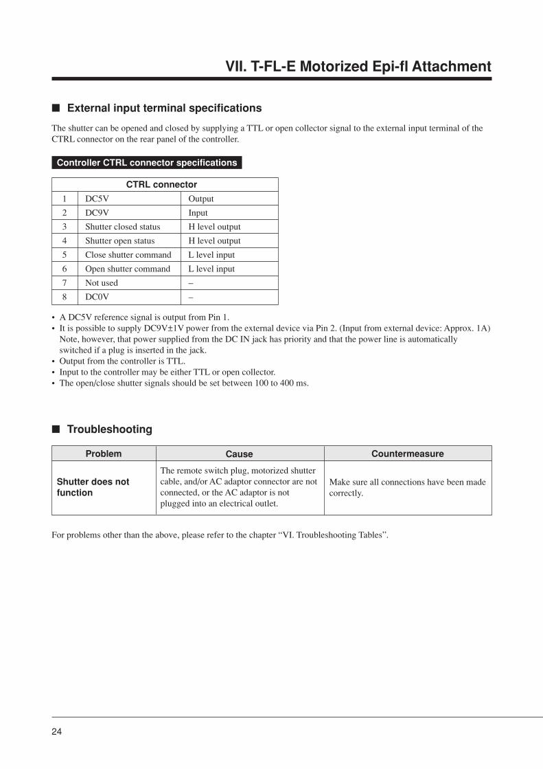
� External input terminal specifications
The shutter can be opened and closed by supplying a TTL or open collector signal to the external input terminal of theCTRL connector on the rear panel of the controller.
Controller CTRL connector specifications
CTRL connector
1 DC5V Output
2 DC9V Input
3 Shutter closed status H level output
4 Shutter open status H level output
5 Close shutter command L level input
6 Open shutter command L level input
7 Not used –
8 DC0V –
• A DC5V reference signal is output from Pin 1.• It is possible to supply DC9V±1V power from the external device via Pin 2. (Input from external device: Approx. 1A)
Note, however, that power supplied from the DC IN jack has priority and that the power line is automaticallyswitched if a plug is inserted in the jack.
• Output from the controller is TTL.• Input to the controller may be either TTL or open collector.• The open/close shutter signals should be set between 100 to 400 ms.
� Troubleshooting
For problems other than the above, please refer to the chapter “VI. Troubleshooting Tables”.
VII. T-FL-E Motorized Epi-fl Attachment
Problem Cause
The remote switch plug, motorized shuttercable, and/or AC adaptor connector are notconnected, or the AC adaptor is notplugged into an electrical outlet.
Countermeasure
Shutter does notfunction
Make sure all connections have been madecorrectly.
25
1 Filter and lens cleaningDo not let dust, fingerprints, etc. get on the lenses or filters. Dirt on the lenses, filters, etc. will adversely affect the viewof the image. If any of the lenses or filters get dirty, clean them as described below.
• Use an air blower to blow away dust. If that does not suffice, brush away the dust with a soft, clean brush, or elsewipe it away gently with gauze.
• To remove fingerprints or grease, use a piece of soft, clean cotton cloth, lens tissue, or gauze moistened with absolutealcohol (ethyl alcohol or methyl alcohol). However, do not use the same area of the cloth, etc. to wipe more thanonce.
• Use petroleum benzine to clean off immersion oil. Wiping with absolute alcohol (ethyl alcohol or methyl alcohol)after the oil has been removed finishes the clean up process.
• If you cannot obtain petroleum benzine, use methyl alcohol. However, because methyl alcohol does not clean as wellas petroleum benzine, it will be necessary to wipe the surfaces repeatedly. (Usually, three or four times is sufficient toclean lenses or filters.)
• Use petroleum benzine only to remove immersion oil from objectives; do not use petroleum benzine for cleaning theentrance lens on the eyepiece tube, filters, etc.
• Absolute alcohol and petroleum benzine are both highly flammable. Handle them carefully, especially around openflames and when turning power switches on and off, etc.
• Follow the manufacturer’s instructions when handling absolute alcohol and petroleum benzine.
2 Cleaning painted componentsDo not use organic solvents such as alcohol, ether, or paint thinner on painted components, plastic components orprinted components. Doing so could result in discoloration or in peeling of the printed characters. For persistent dirt,dampen a piece of gauze with neutral detergent and wipe lightly.
3 StorageStore the system in a dry place where mold is not likely to form.Store the objectives, eyepieces, filter blocks, etc. in a desiccator or similar container with a drying agent.Put the vinyl cover over the system after use to protect it from dust. Before putting on the vinyl cover, turn off thepower switches for the microscope and the Epi-fl attachment light source, and wait until the lamphouse has cooled.
4 Regular inspection (charged)Regular inspection (expenses charged) of this system is recommended to maintain peak performance. Contact yournearest Nikon representative for details about regular inspection.
VIII. Care and Maintenance