team activity: problem 1 on p. 183 – method 2 find the equivalent resistances r 12 & r 34....
Post on 21-Dec-2015
215 views
TRANSCRIPT

Team Activity: Problem 1 on p. 183 – Method 2
• Find the equivalent resistances R12 & R34.
• Find the total resistance RT.
• Find the total current IT.

A Second Example:Parallel Circuits Connected in Series
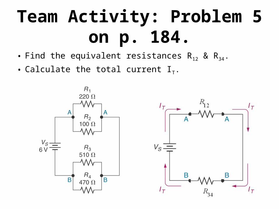
Team Activity: Problem 5 on p. 184.
• Find the equivalent resistances R12 & R34.
• Calculate the total current IT.

Team Activity• Calculate the following equivalent
resistance:
• Rtot = [(R7 + R6)||R5||(R4 + R3)] + (R2||R1)where Ri = i kΩ
• Draw the circuit in Multisim and verify your resistance with the multimeter. Type your mulitmeter reading, your names and your group number on the circuit.
• Turn in your Multisim schematic and your hand calculations.

Wheatstone Bridge
Galvanometer – a sensitive ammeter

Bridge Operation – based on three possible states:
VA = VB VA > VB
VA < VB
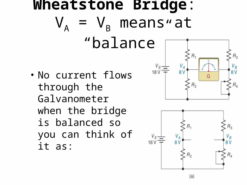
Wheatstone Bridge: VA = VB means at “balance”
• No current flows through the Galvanometer when the bridge is balanced so you can think of it as:

Wheatstone Bridge: A series-parallel arrangement at
“balance”• Resistors R1 and R2 are in series
– R12 = R1 + R2
• Resistors R3 and R4 are in series
– R34 = R3 + R4
• Equivalent resistance R12 is in parallel with equivalent resistance R34

Circuit Analysis at “balance”, galvanometer current =0
2
1 2
4
3 4
2 4
1 2 3 4
2 4
1 3
A S
B S
A B
RV V
R RR
V VR R
V V
R RR R R RR RR R

Application of a Wheatstone Bridge:Smoke Detector
Photoconductive Cells – Light-Controlled Resistors Used as Sensor and Reference
When the amount of light striking the device increases, the resistance decreases (and vice-versa).

Detector Diagram
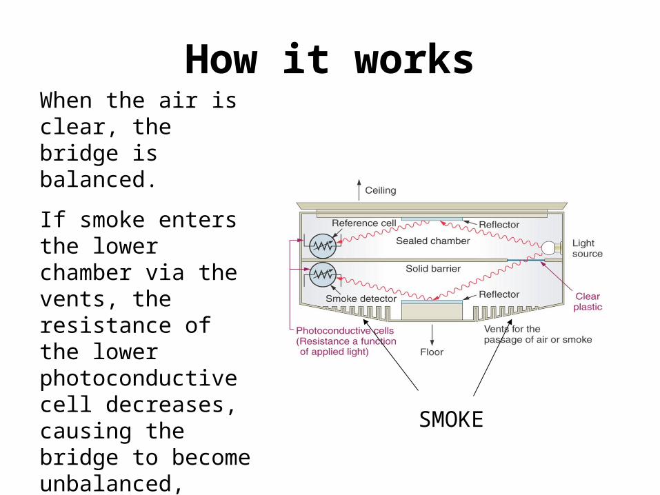
How it worksWhen the air is clear, the bridge is balanced.
If smoke enters the lower chamber via the vents, the resistance of the lower photoconductive cell decreases, causing the bridge to become unbalanced, triggering the alarm.
SMOKE

Switches
• A switch allows you to “make” or “break” the connection between two or more points in a circuit.
• Pole – the moving contact(s)
• Throw – the non-moving contact(s)
• Switches are identified by the number of poles and the number of throws
Switch Reference Material
• Sections 2.8.1 & 2.8.2, pp. 65-67 in your textbook.

Switch Definitions
Two non-moving contacts
One moving contact
Single-Pole Double throw
SPDT – Single-Pole, Double-Throw switch
Already seen in RC Circuits
SPDT
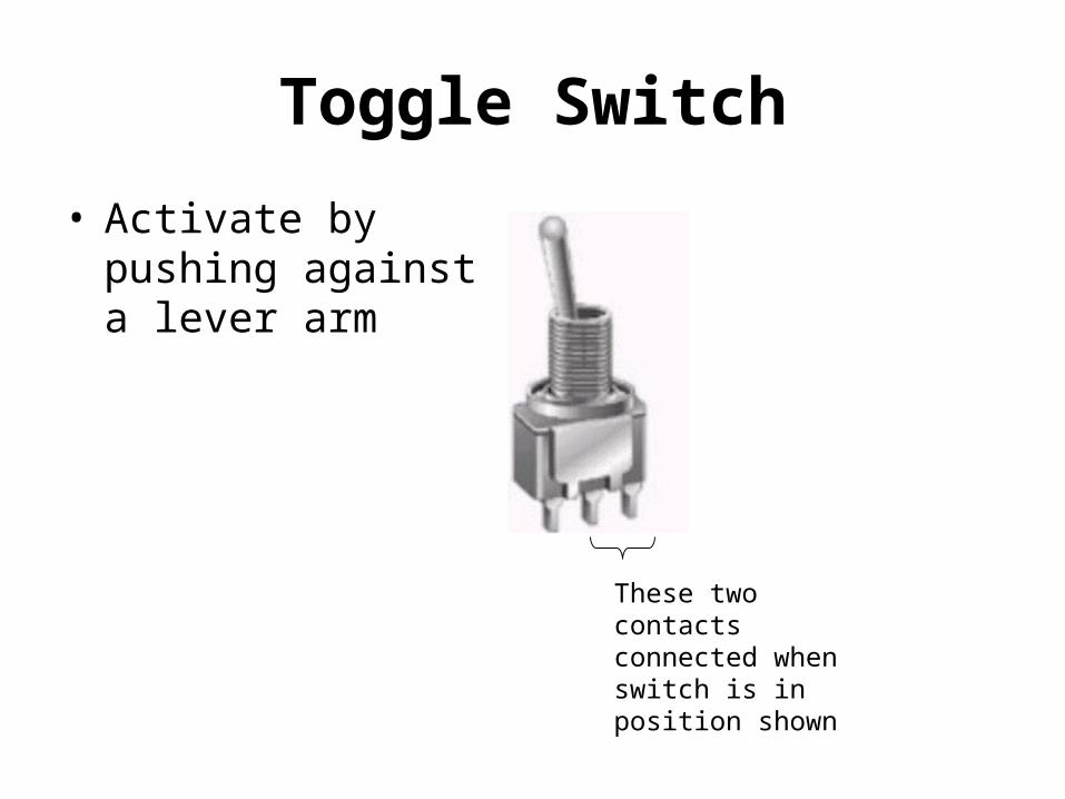
Toggle Switch
• Activate by pushing against a lever arm
These two contacts connected when switch is in position shown
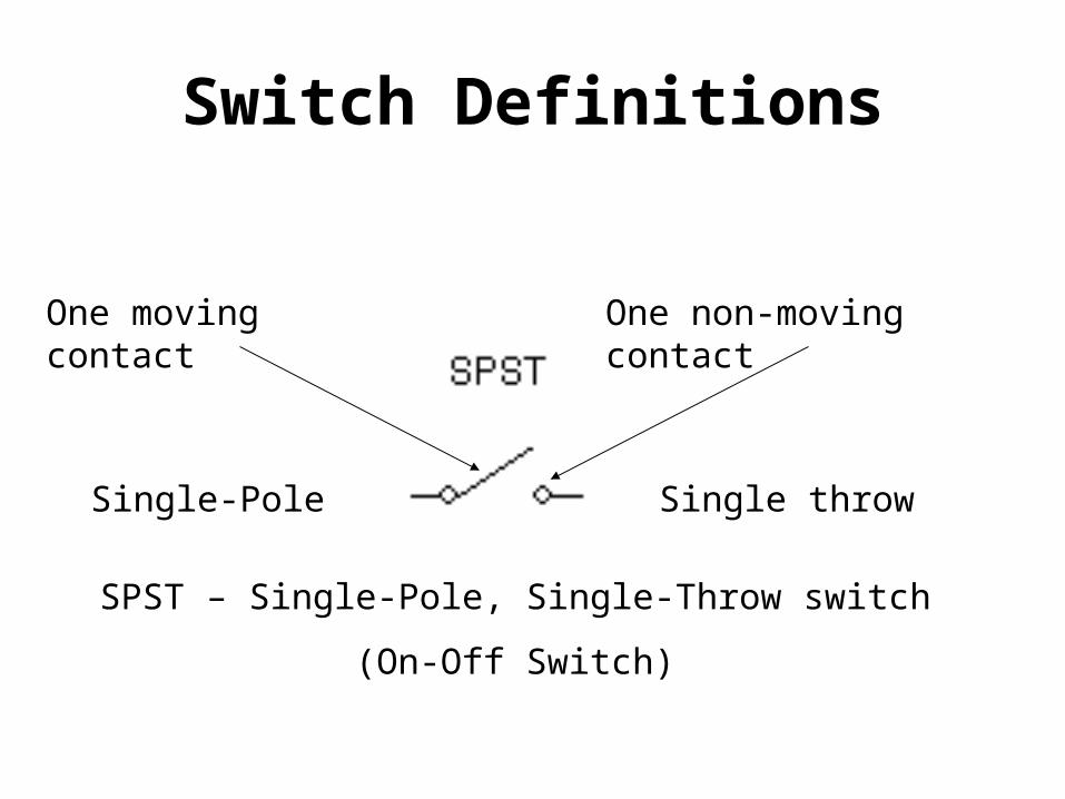
Switch Definitions
One non-moving contactOne moving contact
Single-Pole Single throw
SPST – Single-Pole, Single-Throw switch
(On-Off Switch)
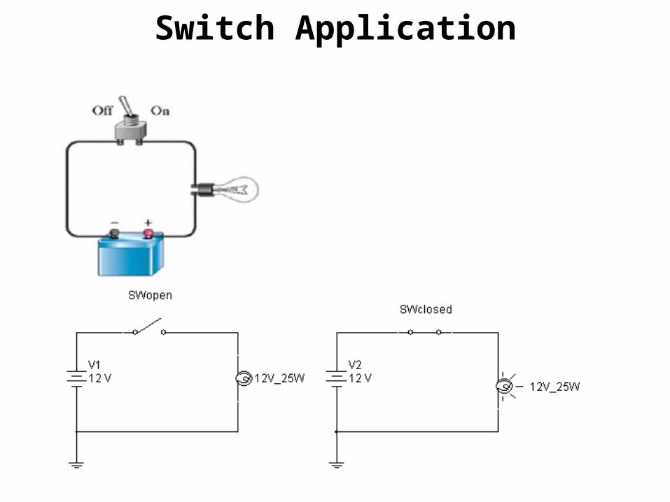
Switch Application

Push-Button Switches
• Activate the switch by pushing a button• Two types of Push-Button Switches• Normally-closed (NC)
– When the button is NOT pushed, the contact is closed
• Normally-open (NO)– When the button is NOT pushed, the contact
is open

Normally-Closed (NC) Normally-Open (NO)