team delteh lunar exavators presents system ... - aman raj · ashish khurana, vaibhav sharma aman...
TRANSCRIPT

TEAM DELTECH LUNAR EXCAVATORS
Presents
SYSTEM ENGINEERING PAPER
“HANDBOOK OF DLE AARAVYA”
STUDENT MEMBERS: Shubham Verma (TEAM LEADER) Arun Kumar Nauhwar, Ashish Kumar, Peeyush, Md Irshadullah Gharbi, Ashish Khurana, Vaibhav Sharma
Aman Raj, Rohan Rathore, Ankit Dahiya
FACULTY Advisors: Asso. Prof N.S. Raghava
Asst. Prof K. Srinivas

As the faculty advisors, we would like to express our support to the Lunabotics Mining Project led
by Shubham Verma, a final year undergraduate student of Delhi Technological University, India.
The team has been religiously working for the last one year on the Research and Development of a
Telerobotic Lunar Excavator and is vehement on participating in NASA‟s fourth annual Lunabotics
Mining competition slated to be held from May 20-24, 2013. We have been associated with the
team in solving their technical problems and guiding them through this venture to fore claim their
vision.
The complete Lunabot has been built under our supervision and the complete System Engineering
process design has been verified by us. We are very hopeful about this project and expect the team
to do well in the competition.
The project “Aaravya” adds to the legacy of Research and Development that Delhi Technological
University (formerly Delhi College of Engineering), India has pioneered over the last seven
decades. We are grateful to NASA for providing such opportunity to our student community which
will enhance their interest in R & D. We support the team‟s initiative and wish them all the best.
N S Raghava K Srinivas
HOD, Computer Center Assistant Professor
Associate Professor, ECE Dept. Mechanical Engineering
Delhi Technological University Delhi Technological University

Contents
1. Agenda
2. Project overview
3. System engineering
3.1 Project objective statement
3.2 Design Process
3.2.1 Development Life Cycle (D.L.C)
3.3 Constraints
3.4Deliverables
3.5 Requirement analysis
3.5.1 Functional requirements
3.5.2 Non functional requirements
3.6 Configuration Management
4. Budget
5. Project planning
6. Evolution of design of lunabot
6.1 First design
6.2 Second design
6.3 Third design
7. Evolution of E& E systems
7.1 Selection of Motors
7.2 Power
7.3 OSIECs
7.4 Embedded Platform
7.5 Communication Setup
7.6 Camera
7.7 Control engineering
8. Final Design of the Lunabot
8.1-8.3 Subsystem
8.4 OSIECs
9. System hierarchy
9.1 Excavation Hardware
9.2 Chassis and Drive train
9.3 Dumping
10. Concept of Operations
11. Characteristics of Final Design
12. Interfacing of various systems
a. Lunarena with lunabot
b. Electronics with Lunabot
c. wireless with lunabot
d. power with lunabot
e. software with lunabot
13. Regolith Analysis
14. Risk Management
Appendix

Abbreviations
STEM : Science technology engineering math
SOFT : Survival of fittest (trade of tables)
OSIEC :open source integrated electronics circuit
COTS :commercial off the self
POS : project/process objective statement
Content of tables
S.O.F.T 1- selection of motor
S.O.F.T 2- selection of battery
S.O.F.T 3- various drive trains
S.O.F.T 4- different excavation mechanisms
S.O.F.T 5- various locomotion mechanisms
S.O.F.T 6- various dumping mechanisms
S.O.F..T 7-selection of MOSFET Drivers
Content of figures :
Fig 1: Semantics of Waterfall Model
Fig 2: First Design
Fig 3: Second Design
Fig 4: Third Design
Fig 5: Container side views
Fig 8: Comparison of Batteries on Wh/Kg
Fig 9: Circuit design methodology
Fig10: Circuit measuring RPM count of motor from encoder,atmega32
Fig 11: Circuit setup of RPM measurement of motor
Fig 12: Communication setups
Fig13: Feedback from motor to atmega32
Fig 14: Motor control algorithm
Fig 15: Specifications of motor used
Fig 16: MOSFETs specifications
Fig 17: MOSFET driver specification
Fig18. Main Hierarchical model
Fig 19: Operational model of lunabot
Fig 20: Signal Flow
Fig 21: Mechanical Con-ops
Fig 22: Electrical Con-Ops
Fig 23: Bucket Ladder
Fig 24: Chassis with caterpillar track mechanism
Fig 25: Top view of the container
Fig 27: Highlighted region shows the ‘L’ Clamp
Fig 28: Highlighted region shows the 4 bar mechanism
Fig 29: Marked sections showing motors and chains of container
Fig 30: Rake angle and solid density curves
Fig 31: Wireless setup
Fig 32: Arduino interfacing with mechanical
Fig 33: Power interfacing
Fig 34: Software model

Fig 35: Van Shear Test
Fig 36: Lab test of regolith sample
1. AGENDA
DelTech Lunar Excavators used the mantra of abstract
analysis and practical experimentation to decipher each
and every aspect of Aaravya, the Lunabot.
The first step was to understand the competition, its
rules and regulations and what NASA is looking in a
Lunabot. The team then studied about robotics,
particularly excavators and analysed the past
participants of the competition to get a fair idea of what
the demands of the competition are and made a
schedule of work to assign specific tasks for each
month and planning was done until the beginning of the
competition at Florida in May, 2013.
The team decided to tackle each aspect of the Lunabot
independently one at a time. As a result, the Lunabot
was divided into 3 main sub-systems as shown in figure
1:
Excavation
Chassis and Locomotion
Dumping
Fig 1: Sub systems of Lunabot
The above systems were further subdivided into
Mechanical and Electrical systems to achieve division
of labour and efficiency. Understanding the fact that
space missions like excavation on the Moon involves
lot of funds putting the constraints on payload and
energy requirements. It was decided that the aim of the
team would be to reduce weight, use economical
materials without compromise on quality and use least
amount of energy. With the above objectives in mind,
the team set out to build a Lunar Excavator that could
achieve all the objectives and give fresh new
perspectives by enthusiastic undergraduates to a reputed
organisation like NASA. Every parameter of the
Lunabot along with its interaction with the environment
was tested by rigorous experimentation. The results
were inferred and used to design our Lunabot.
All possible designs were tested and then these were
ranked on various grounds. Weighted point method was
used to select the best design which optimizes between
simplicity, cost, efficiency and weight. After selection
of the final design, the system engineering process laid
emphasis on designing each component carefully.
Various models were studied to finalise the components
of the Lunabot and their interaction with the
environment.
The competition is of great importance to not only us
but technological manpower all over the world. The
team used this platform to promote STEM ( Science,
technology, Engineering and Mathematics) among
young students and undergraduates. The team realised
its shared dream of being able to solve real world
problems as engineers. The world needs, man to use ,its
technological prowess to make the world a better place.
Mining resources on the Moon and other celestial
bodies will also be very important in the future as the
resources on Earth keep on depreciating.
Thus having all these parameters in mind, the team
embarked on a mission to showcase its bravura and
build an excavator that could, in future, be capable of
actually mining regolith on the moon.
2. Project Overview
NASA's “Lunabotics Mining Competition” is an
international competition for the University students
pursuing a course in the field of science and
technology, designed to engage and retain students in
science, technology, engineering and mathematics
(STEM) and promote a high level of interest in space
related activities. In the process of doing so, NASA
which has pioneered in space exploration will benefit
by possibly finding new concepts and solutions to the
difficulties presented by different teams for excavating
regolith, which could later be applied in actual lunar
missions and can also help in setting up a human base
on moon for collecting regolith which can be processed
to obtain vital substances such as water and oxygen;
therefore, machinery that mines and transports regolith
Lunabot
Excavation Chassis and Locomotion
Dumping
1

is likely to be an important component of future moon
missions.
The various parts of the competition and rules &
regulations are:
1. Onsite mining which seeks the young
enthusiasts to design and build a
wirelessly/autonomously governed robot that
can traverse an obstacle area, collect regolith
simulant in the mining area, then travel back
across the obstacle area and deposit the mined
material in a collection bin.
2. Other categories of the competition include
team spirit ,outreach project, system engineering
paper and slide presentation.
3 System Engineering
3.1 Project Objective Statement
To develop an innovative yet simple and robust
Lunabot design adhering to the rules of competition ,
OSIECs and commercially off the self-parts within
budget constraints by workforce of four students in
eight months .
3.2 Design Process
3.2.1 Development Life Cycle (DLC)
The Lunabot‟s design analysis started with the very
idea of keeping the level of project adherent with
industrial projects which urged the team to complete
its objectives using an industrial software model, so that
the team can have future insight and track of the project
.After requisite research and studying different models
i.e V model , Prototype model , Spiral model the team
chose the simple waterfall model with main focus on
the maintenance and testing as the lunabot‟s product
definition was stable and also the team had no
ambiguity about the final design and requirements .
It is a linear sequential life cycle model and in this DLC
model each phase is completed before start of next
phase ,with identifiable deliveries to the next phase. At
the end of each phase, a review takes place to determine
if the project is on the right path or not.
This model helped the team in structuring a proper plan
as the members used to have team meetings and team
review after each phase so errors and future problems
were minimized to the extent that the members came
across only a few problems in our design‟s
implementation and integration. The team assumed that
a detailed documentation from the design phase can
significantly reduce the implementation effort. The
team was emphatic towards testing, so even before
integration phase; testing was started on different
modules separately. A detailed diagram, in fig 2, shows
how the process unfolded.
Fig 2. Semantics of Waterfall Model
3.3 Constraints
As given in the NASA‟s rulebook for the competition
the team must adhere to following rules and constraints:
1. Dimension of lunabot: 1.5m X 0.75m X 0.75m, with
height must not be more than 0.75 and base and
length are interchangeable as per convenience .
2. Weight of Lunabot: it must not exceed 80kg,
exclusive of communication part not attached to
lunabot and control room part of system.
3. Time limit: 10 minutes for operation and 5 minutes
for removal of hardware from lunapit.
4. Emergency Red Button: It must be present to stop all
functioning of lunabot at once.
5. Bandwidth: average 5Mbps may be used for all
purposes.
6. Wireless: Network communication should abide by
802.11b/g IEEE protocol.
The team tried its best to abide by these rules.
2

3.4 Deliverables
In order to achieve the Project objective statement, the
deliverables are:
1. Fully functional lunabot adherent with competition
rules and constraints.
2. Robust and simple design within budget constraints.
3. System engineering paper structured on guidelines
provided by NASA‟s rulebook.
4. A Slide presentation showing the various
parameters stated in the rulebook.
5. An Outreach project document showing the team‟s
endeavor to disseminate the ideas of STEM .
6. A Video showing at least one complete cycle of
operation.
3.5 Requirement Analysis
3.5.1Functional requirements
1. The lunabot shall be operational for 20 minutes
continuously.
2. The lunabot shall excavate the BP-1 (Regolith
simulant)
3. The lunabot shall dump the BP-1 into hopper which
is at height of 0.75 from ground.
4. The lunabot shall operate from the control room with
complete visual and auditory isolation.
5. The lunabot shall navigate through the craters and
boiler placed in the obstacle zone.
6. The lunabot shall not throw dust while in operation.
7. The lunabot shall not use any component,
technology or process that wouldn‟t work on lunar
surface or that is dependent on gravity .
8. The lunabot shall be self-powered.
3.5.2 Non Functional requirements Reliability requirement
1. It shall work for 20minutes continuously with battery
2. It shall have proper housing for the circuitry to avoid
dust.
Efficiency requirement
1. It shall excavate at least 10 kg of regolith in 10
minutes.
2. It shall use average 5Mbps while in operation.
3. It shall maneuver lunapit obstacle zone without
getting toppled or falling in the crater.
Safety requirements
1. The lunabot shall have emergency red button to halt
all operation and 5cm in diameter.
2. The robot shall not use any explosives or dangerous
part
3.6 Configuration management (CM)
Configuration Management is an integral part of
today‟s industry system engineering process and is
used for establishing and maintaining consistency of a
product's performance, functional and physical
attributes with its requirements, design and operational
information throughout its life for the lunabot project.
Massive file work and documentation in initial phase of
the project lead the team to rethink the strategy and to
create proper system and indexing for better and
efficient use of resources and parts of repository at the
team‟s disposal. Firstly for documentation and paper
work the team created google group with mailing list
and separate thread for each subsystem and scheduled
deadlines. Proper documentation was created regarding
indexes, naming files, managing parts and repository of
components.
4. BUDGET
The varied parameter of the lunabot design that was
considered exhaustibly for better scheduling of budget:
i. Open Source Integrated Electronic Circuits (OSIECs)
ii. Motors, sharing the largest part of the budget, were
used motors
iii. Worm gear were designed on milling machine
iv. Cheapest alloy of Aluminium was considered.
Estimated Budget 4545$
Actual Investment 1540$
The detailed budget is provided in Appendix 2
0 50000 100000
Excatavtion
Locomotion
Dumping
Control
Infrastructure
Esmitaed cost
Actual cost
Fig 4: Budget comparator
3

5. Project Planning
In its advent of following the sequential
mode(waterfall model) , the team created a detailed
and tentative work plan from start to finish .The team
tried their best to stick to the work plan and was
successful in meeting the deadlines . Fig 5 given below
is the work plan which the team created in beginning of
project .It was divided in the five phases .The schedule
for each phase was developed only after completion of
the previous phase.
Given below is the work plan developed one phase at a
time.
Pre-phase A: (10/8/2012 to 30/8/2012)
Phase A: (31/8/2012 to 10/9/2012)
Phase B: (11/9/2012 to 30/9/2012)
Pre-phase C: (10/10/2012 to 20/11/2012)
Pre-phase C cont:
Phase C: ( 15/11/2012 to 10/1/2013 )
Phase D: (17/1/2013 to 25/3/2013)
Phase E: (16/3/2013 to 10/5/2013)
Fig 5: Work plan
Fig 6. Planner comparator
In the above figure we have drawn a bar graph showing
the variation between time estimated for a phase before
start and the actual time it took to complete the phase .
X-axis shows the number of days and Y-axis shows the
phases completed. Looking at the statistics we missed
two deadlines and were ahead of time in meeting two
deadline so the total estimated time till completion of
phase D was approximately 210 days and actual time
till completion of phase D is 203 so percentage
efficiency of our estimation prediction was 98.59%
.phase E is not considered in the calculation as it is in
progress .
Studied the rules and regulations of the competition
Referred to videos and papers of the previous year teams
Contoured the basic design of the robot.
Dealt with anatomy of the various proclaimed designs of the bot.
Procured knowledge of the various hardwares used in bots.
Procured knowledge of various softwares required.
Produced a detailed design of hardware requirements and technology
Produced a detailed design of software requirements and interfaces.
Sorted the most suitable and robust design.
Solid works design and analysis.
Formed a basic prototype of chassis.
Structured a model of container and bucket.
Approached faculty for lab procurement.
Encryption of a formal proposal.
Purchasing , manufacturing parts of chassis
Purchasing , manufacture parts of ladder system
Purchasing manufacure of dumping system parts
Assembling the various parts of locomotion system
Assembling the various parts of dumping system
Assembling the various parts of ladder system
Assembling all module of lunabot .
Testing the Lunabot for funtionality and Extrapolation of results.
completion of system engineering paper , outreach project,slide ppt.
0 20 40 60 80
Pre-phase A
phase A
phase B
pre-phase C
phase C
phase D
phase E
Actual Time
Estimated Time

6. Evolution of Design of Lunabot
6.1 Primitive Design
The team structured with a primitive design based on its
initial research as shown in Fig 7
Fig. 7 Primitive Design
Bucket wheel is chosen as digging mechanism. The
idea behind this selection was to get a continuous and
quick digging mechanism. Regolith collected from
bucket wheel was emptied into the container by taking
the wheel above the container and rotating it in opposite
direction. This made mechanism complex and the
process involves a lot of dust generation. Tracked
wheels are used for locomotion. For dumping the
collected regolith into the NASA‟s collection bin a
smaller bucket ladder is attached and vibrators provided
at the bottom for empting the container.
The system seemed complex with multiple degrees of
freedom and the stability of lunabot is questionable.
6.2 Second Design
This design was an amalgam of two different design
mechanism used in tandem.
Fig 8 Second Design
Bucket wheel was again chosen as digging mechanism
with a slight modification in the mode of transfer of
regolith to container. Regolith excavated by wheel was
transferred to a small bucket ladder which in turn
dumps it into collection bin. The process was
continuous and dust free. A four wheel differential
drive mechanism is chosen for locomotion. Dumping of
regolith is done using crane/winch mechanism and
tilting the container to dump all the regolith in NASA‟s
bin. This saved a lot of time especially while digging
and dumping. The digging system entails high degree
of synchronization between bucket wheel and bucket
ladder. Dumping system was not rugged and stable.
6.3 Third Design
Fig 9. Third Design
Fig 10. Container side views
4 5
τ α i (Current drawn)
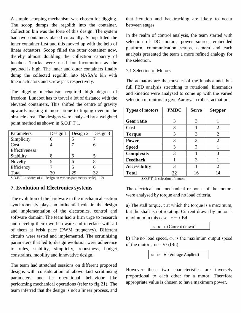
A simple scooping mechanism was chosen for digging.
The scoop dumps the regolith into the container.
Collection bin was the forte of this design. The system
had two containers placed co-axially. Scoop filled the
inner container first and this moved up with the help of
linear actuators. Scoop filled the outer container now,
thereby almost doubling the collection capacity of
lunabot. Tracks were used for locomotion as the
payload is high. The inner and outer containers finally
dump the collected regolith into NASA‟s bin with
linear actuators and screw jack respectively.
The digging mechanism required high degree of
freedom. Lunabot has to travel a lot of distance with the
elevated containers. This shifted the centre of gravity
upwards making it more prone to tipping over in the
obstacle area. The designs were analysed by a weighted
point method as shown in S.O.F.T 1.
Parameters Design 1 Design 2 Design 3
Simplicity 6 5 7
Cost
Effectiveness
4 7 6
Stability 8 6 5
Novelty 5 6 8
Efficiency 7 5 6
Total 30 29 32 S.O.F.T 1: scores of all design on various parameters scale(1-10)
7. Evolution of Electronics systems
The evolution of the hardware in the mechanical section
synchronously plays an influential role in the design
and implementation of the electronics, control and
software domain. The team had a firm urge to research
and develop their own hardware and interface with all
of them at brisk pace (PWM frequency). Different
circuits were tested and implemented. The scrutinising
parameters that led to design evolution were adherence
to rules, stability, simplicity, robustness, budget
constraints, mobility and innovative design.
The team had stretched sessions on different proposed
designs with consideration of above laid scrutinising
parameters and its operational behaviour like
performing mechanical operations (refer to fig 21). The
team inferred that the design is not a linear process, and
that iteration and backtracking are likely to occur
between stages.
In the realm of control analysis, the team started with
selection of DC motors, power source, embedded
platform, communication setups, camera and each
analysis presented the team a more refined analogy for
the selection.
7.1 Selection of Motors
The actuators are the muscles of the lunabot and thus
full FBD analysis stretching to rotational, kinematics
and kinetics were analysed to come up with the varied
selection of motors to give Aaravya a robust actuation.
Types of motors PMDC Servo Stepper
Gear ratio 3 3 1
Cost 3 1 2
Torque 3 3 2
Power 3 3 2
Speed 3 2 1
Complexity 3 1 3
Feedback 1 3 1
Accessibility 3 1 2
Total 22 16 14
S.O.F.T 2: selection of motors
The electrical and mechanical response of the motors
were analysed by torque and no load criteria.
a) The stall torque, τ at which the torque is a maximum,
but the shaft is not rotating. Current drawn by motor is
maximum in this case. τ = ilBd
b) The no load speed, ω, is the maximum output speed
of the motor ; ω = V/ (lBd)
However these two characteristics are inversely
proportional to each other for a motor. Therefore
appropriate value is chosen to have maximum power.
ω α V (Voltage Applied)

7.2 Power Source
The selection was mainly weighed on the weight of the
battery system and availability, as weight marked a
specific consideration of points allocation in the
competition. Potential Battery Types that we consider
as viable power sources are: Valve Regulated Lead
Acid (VRLA) , Nickel Cadmium (NiCad), Nickel Metal
Hydride (NiMH) ,Lithium Polymer (LiPo). During the
selection among different types of battery , the
parameters that we considered are – Specific Energy,
High Discharge Power, Self Discharge Rate , Weight &
Cost.
Fig 11: comparison of Batteries on Wh/Kg
S.O.F.T 3: selection of battery
Hence LiPo battery was selected.
7.3 Open Source Integrated Electronic Circuits(OSIECs)
OSIECs were designed by the team inline with the
endeavor to learn by implementing things of their own.
The requirements were analysed by searching problem
statements on forums and developing the used circuit
with its further evolution by testing. During the
development of lunabot the team tried to develop the
systems and circuits indigenously. The team
understands not only the implementation of various
systems and sub-systems used in fabrication but also its
functionality, this helps in better debugging and
improves productivity.
7.4 Embedded Platform
The team started working with Atmega32 in the
platform of AVR Studio 5 . Interfacing of motors using
serial data transmission and through Infrared Remote
control were done to analyse the behavior of motors
speed with PWM & wireless control. The resultant
circuit for serial communication utilizing Max232 IC
was built, soldered and used.
. Fig 13: circuit measuring RPM count of motor from encoder,atmega32
6.5 Communication Setup
7.5 Communication Setup
The rules stated to control the lunabot either through a
wireless channel or design it with autonomous
credibility. The team decided to implement the design
requirement realisation
simulation on breadboard and
software
soldering and implementation
Parameters VRLA NiCad NiMH LiPo
Specific Energy 1 1 2 4
High Power
Capability
5 5 5 5
Low Self
Discharge
3 3 3 4
Weight of 100 A-h 1 2 1 4
Low Cost 5 3 3 1
Total 15 14 14 17
Fig 12: circuit design methodology
Fig 14: circuit setup of RPM measurement of motor

with wireless features. The lunabot needed to be in
compliant with 802.11b/g IEEE protocol.
Fig 15: Communication setups
Communication channels involved:
1. Wireless medium :router to wi-fi and camera to
control room
2. Serial communication: wi-fi module to robot
7.6 Camera
As our lunabot is visually and auditory isolated from
control room so we are depending on the camera‟s
video output to control our lunabot. We will be using IP
camera, as it reduces the number of processes handled
by the microprocessor. Wireless ip camera provides its
own web server where image captured by the camera
can be view from any computer with internet access.
10BASE-T Ethernet signals provide transmission
speeds upto 10 Mbps. Devices are connected to the
cable and compete for access using a Carrier Sense
Multiple Access with Collision Detection (CSMA/CD)
protocol.
7.7 Control Engineering
Control is a very important parameter that needs to be
adhered to for better functionality of the lunabot. The
team learnt that it is very difficult to realize a linear
system. A finer blend of feedback and linear system
analysis was procured for a finer control. The
telerobotic system is a typical hybrid system that
contains both continuous time and discrete event
dynamics as example the robot can be considered as a
continuous time system modeled customarily by
differential equations or difference equation, and the
human operator whose function is to generate the
commands for the robot located in the remote side,
however, can be modeled as discrete event dynamics.
Fig 16: feedback from motor to atmega32
A basic mathematical modeling of the lunabot system
was studied and analysed. The most nonlinear element
in the model is the DC motor. Its behavior on
application of load shows nonlinear characteristics that
further are reciprocated in the non-linearity of the
lunabot. The team, thus, decided to improve linearity by
using encoders and PID algorithm in lunabot design.
user sends
command
Router
wi-fi module on Bot
robot moves
camera
Fig 17: Motor control algorithm

8. Final Design of the Lunabot
8.1. Chassis/Drivetrain
4130 alloy steel square tubing is used. A part of chassis
for installing bucket ladder inclined at 54.34 deg.
Drivetrain has four wheels with two rear drive train
motors. Timing belt is chosen as inferred by following:
Characteristics Flat
belt
V -
Belt
Triplex
Chain
Timing
Belt
Slipping 2 5 8 8
Load Capacity 3 7 9 7
Weight 9 8 1 8
Max permissible
tension
5 6 9 7
Total 19 26 27 30 S.O.F.T 4: various possible drivetrains
8.2. Bucket ladder system
70 cm tall single-chain bucket ladder which articulates
up and down through the use of a link and was powered
by a motor.
The tip of the bucket ladder moves downward and
directly over the collection bucket to avoid dust
generation.
The bucket ladder will move up and out of the way of
the collection bucket when the collection bucket is
raised for dumping.
The Bucket Ladder system had following advantages :
Requires less power and force.
Multiple excavation buckets adds continuity
,hence less time consumption which makes
excavation process reliable.
The mass of the bucket ladder is more uniformly
distributed than a front-end loader.
8.3. Elevator dumping system
• Dumping mechanism is having a collection bin, which
would move up and down along two screws to a given
height.
Screw arrangement driven by a motor to move the bin
to and fro.
Stopping of bin was achieved by switching off the
motor. Rear face of the container was brought down
using an actuator to let the regolith flow out of it.
SPECIFICATION OF MOTORS
After analysis of the lunabot design the team chose
motors with following specifications. (refer appendix A
for calculation of specs.)
Motors Operating
Voltage (V)
RPM Torque
(Nm)
Caterpillar 18 100 70
Bucket Ladder 18 80 35
Dumping 18 65 70
18 75 15
8.4 OSIECs
The team tried to exploit the knowledge in open source
realizing the various interfacing circuits for the project.
The algorithm used is as depicted in fig 9 .
H bridge: A lot of design analysis was carried on in
coming up with its circuit. The approach that led to
design of the circuit:
i. Testing the motors for their stall current.
The tests presented a remarkable insight in deciding on
to the power systems, electrical interfacing and
switching components selection. The team used a basic
series testing circuit of which the details and
observations are presented in APPENDIX 3. Stall
condition of the motor was sensed as one of the worst
case guideline, a part of Risk Management, and thus
circuit is designed with a factor of safety of 5.
ii. Trade off analysis of switching elements
The design involved as its first level of selecting the
switching elements. The parameters considered are
price, speed, threshold voltage(Vt),Max power
dissipation(Pmax),Vgs/Vbe on the scale of 5. Packaging
is considered thoroughly for it needed to be good for
PCB soldering, TO-220 or TO-92 thus wee considered,
further TO-220 for its embedded heat sink.
Fig 18: specifications of motor used

Elements Price Speed Vt Pmax Vbe/Vgs
BJTs 2 1 4 2 1
MOSFETs 4 5 1 4 3
S.O.F.T 5 Switching components selection
Inference: MOSFETs are considered as switching
element with 17 points.
iii. Selection of components
The Power MOSFETs were chosen to design the
circuit. The NMOS inverter and CMOS inverter were
analysed with different parameters.
Parameters CMOS NMOS
Switching Action 4 2
Power dissipation( & Rds) 2 4
Complexity 5 2
Price 3 4
Availability (Free
samples)
4 2
Total 18 14 S.O.F.T :6 CMOS v/s NMOS H bridge
Inference: This led to the decision of choosing the
CMOS circuit to be implemented in our lunabot.
Specification of mosfets chosen for the implementation
of NMOS inverter were as follows:
Part Number Voperating Ioutput Pmax
1. PMOS (IRF4905) -55V -74A 200W
2. NMOS
(IRFP064N)
55V 110A 200W
3.NMOS(P55NF06) 60V 50A 110W
4.PMOS(SUM11P08) -80V -110A 125W
The mosfet used has some gate capacitance which is to
be charged and discharged for en efficient switching
action. These were driven by Mosfet drivers. The
required output current provided by mosfet drivers can
be calculated as follows:
The output current depends upon the gate capacitance
of the mosfets and voltage applied across the gate and
source of the mosfet.
If ∆Qgs is saturation charge which can be stored across
the gate and source terminals of the mosfet. It must be
charged and discharged in time ∆t which is switching
time of the mosfet, which further is decided by the
∆Qgs = Cg x ∆Vgs ,where Cg is the gate capacitance
of the mosfet. So the current provided by the driver
must be equal to
Io = ∆Qgs/∆t = Cg .∆Vgs/∆t
Putting the values form datasheet, the required current
came out as 2Amp , and then the type of mosfet drivers
are chosen using following table.
Parameters Driver ICs Transistor
Switching speed 5 3
Cost 2 5
Current 4 3
Complexity 2 5
Safety 3 2
Total 16 18
According to above table, Transistors having higher
points were considered.
Following transistors were chosen according to purpose
and have following specification.
Parameters TIP122 CDIL2N6107
Vbe 5V 5V
Vt 2.5V 1.5V
Ic 5A 10A
Packaging TO-220 TO-220
Pdissipation 65W 40W
Fig 19: MOSFETs specifications
S.O.F.T :7: selection of MOSFET Drivers
Fig 20: MOSFET driver specification

9. System Hierarchy
The team vision for the systematic hierarchical model
of the lunabot was divided not on the engineering
backgrounds but on the aspects of operation. Thereby
the team focused upon the various parameters that were
provided as the guidelines (rulebook) that led to the
decision to implement the bot at the very level of
functionality. The execution process was more
systematic and defined as the team had better
interfacing with various functional characteristics and
behavior of the lunabot. Aaravya was divided into basic
operational characteristics as Excavation, Drivetrain
and Dumping which were further classified on the
engineering grounds so as to understand the basic needs
of the system at more adept level.
Fig 21. Main Hierarchical model
The sub-division of each operational feature was on the
following parameter:
Mechanical
Electronics
Electrical and Control
Software
9.1 Excavation Hardware
9.2 Chassis and Drive train
9.3 Dumping
LUNABOT
EXCAVATION CHASSIS AND DRIVETRAIN
DUMPING
WIRELESS TRANSER
Mechanical
Chain with brackets
Bucket
Sprockets
Ladder
Electronics
Motors
Power Source
Encoders
MCU
Software and Interfacing
Interfacing the motors for chain
movement and for ladder motion with
the joysick
Mechanical Components
•Chassis
•Wheels
•Belt with threads for better grip
Electronics Components
•Motors
•Power Source
•Controller with ethernet shield
•MCU board, microcontrollers and Programmers
•Router- to recieve the wireless signal
Software and Interfacing
•Interfacing the motors for chain movement and for ladder motion with the joysick
•User Interface for camera
The Power Source which was being used is a 6 cell
battery 22.9V, Ah, 20C. The controller being used is
the arduino due board and WRT 54GL router was used
to receive and broadcast signals.
•Storage Container
•Wheels
•Screw jack mechanism to lift the box
Mechanical Components
•Motors for opening the gate
•Power Source Electronics Components
•Interfacing the motors for raising the container and then opening the backside.
Software and Interfacing

LUNABOT
MECHANICAL
SOFTWARE
ELECTRONICS Power Button
Control Command
Router Signals
Telecom Feedback
Camera
Fig 25 Electrical Con-Ops
10. Concept of Operations
The Con-Ops of the system can be explained by stating
the required tasks that has to be done along with the
technical know-how, that the end-used will need to
complete the required job.
Lunabot at its highest level can be divided into three
subsystems under two categories as follows:
o Mechanical Subsystem
o Electronics Subsystem
o Software Subsystem
These three subsystems are interfaced by the
engineering principles to each other as shown in
figure:
System Structure
Lunabot was interfaced with its environment through
various sensors and actuators. Rotary encoders return
feedback to the microcontrollers which control the
locomotion speed. Feedback from camera gives end
user the valuable visual feedback from which he can
send the necessary control signal via the router from
the control room.
Fig22: operational model of lunabot
Fig 23: Signal Flow
Fig 24: Mechanical Con-ops
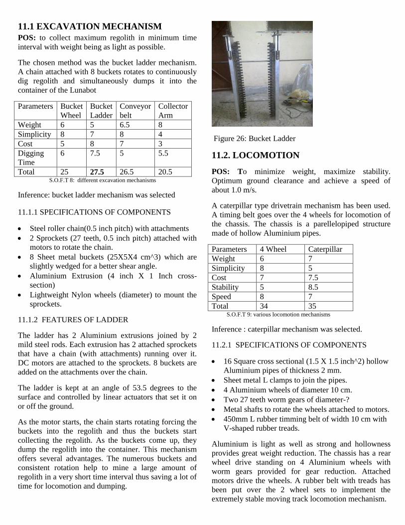
11.1 EXCAVATION MECHANISM
POS: to collect maximum regolith in minimum time
interval with weight being as light as possible.
The chosen method was the bucket ladder mechanism.
A chain attached with 8 buckets rotates to continuously
dig regolith and simultaneously dumps it into the
container of the Lunabot
Parameters Bucket
Wheel
Bucket
Ladder
Conveyor
belt
Collector
Arm
Weight 6 5 6.5 8
Simplicity 8 7 8 4
Cost 5 8 7 3
Digging
Time
6 7.5 5 5.5
Total 25 27.5 26.5 20.5 S.O.F.T 8: different excavation mechanisms
Inference: bucket ladder mechanism was selected
11.1.1 SPECIFICATIONS OF COMPONENTS
Steel roller chain(0.5 inch pitch) with attachments
2 Sprockets (27 teeth, 0.5 inch pitch) attached with
motors to rotate the chain.
8 Sheet metal buckets (25X5X4 cm^3) which are
slightly wedged for a better shear angle.
Aluminium Extrusion (4 inch X 1 Inch cross-
section)
Lightweight Nylon wheels (diameter) to mount the
sprockets.
11.1.2 FEATURES OF LADDER
The ladder has 2 Aluminium extrusions joined by 2
mild steel rods. Each extrusion has 2 attached sprockets
that have a chain (with attachments) running over it.
DC motors are attached to the sprockets. 8 buckets are
added on the attachments over the chain.
The ladder is kept at an angle of 53.5 degrees to the
surface and controlled by linear actuators that set it on
or off the ground.
As the motor starts, the chain starts rotating forcing the
buckets into the regolith and thus the buckets start
collecting the regolith. As the buckets come up, they
dump the regolith into the container. This mechanism
offers several advantages. The numerous buckets and
consistent rotation help to mine a large amount of
regolith in a very short time interval thus saving a lot of
time for locomotion and dumping.
Figure 26: Bucket Ladder
11.2. LOCOMOTION
POS: To minimize weight, maximize stability.
Optimum ground clearance and achieve a speed of
about 1.0 m/s.
A caterpillar type drivetrain mechanism has been used.
A timing belt goes over the 4 wheels for locomotion of
the chassis. The chassis is a parellelopiped structure
made of hollow Aluminium pipes.
Parameters 4 Wheel Caterpillar
Weight 6 7
Simplicity 8 5
Cost 7 7.5
Stability 5 8.5
Speed 8 7
Total 34 35 S.O.F.T 9: various locomotion mechanisms
Inference : caterpillar mechanism was selected.
11.2.1 SPECIFICATIONS OF COMPONENTS
16 Square cross sectional (1.5 X 1.5 inch^2) hollow
Aluminium pipes of thickness 2 mm.
Sheet metal L clamps to join the pipes.
4 Aluminium wheels of diameter 10 cm.
Two 27 teeth worm gears of diameter-?
Metal shafts to rotate the wheels attached to motors.
450mm L rubber timming belt of width 10 cm with
V-shaped rubber treads.
Aluminium is light as well as strong and hollowness
provides great weight reduction. The chassis has a rear
wheel drive standing on 4 Aluminium wheels with
worm gears provided for gear reduction. Attached
motors drive the wheels. A rubber belt with treads has
been put over the 2 wheel sets to implement the
extremely stable moving track locomotion mechanism.

The Lunapit surface provided by NASA is irregular,
bumpy and has craters. Stability of the Lunabot
becomes very important in this scenario. The caterpillar
mechanism with the large contact area provided by the
belt with treads gives that extra stability and prevents
slipping or toppling.
The hollow parellopiped structure provides extreme
weight reduction and gives considerable amount of
ground clearance so that the small craters and boulders
can be easily traversed without having to realign the
Lunabot.
Figure 27: Chassis with caterpillar track mechanism
11.3 DUMPING
POS: To store as much regolith as possible and dump
the regolith smoothly and quickly.
The method chosen is one of a raked container which is
lifted by two screw jacks to the required height and as
the container opens from one side, the regolith flows
along the rake to the bin.
Parameters Pulley and
Rails lifting
mechanism
Screw jack
Lifting
mechanism
Conveyor belt
Dumping
mechanism
Weight 5 7 8
Simplicity 4 6.5 6
Cost 8 8 4
Lifting
Stability
3 7 8
Time Taken 6 6 5
Total 26 34.5 31 S.O.F.T 10: various dumping mechanisms
Inference : screw jack mechanism was selected.
11.3.1 SPECIFICATIONS OF CONTAINER
A 40X37X40 cm^3 sheet metal container.
Metal angular stand with a rake angle of 10 degrees.
An 18 gauge metal sheet attached at the base of the
container giving a rake angle of 25 degrees.
Figure28: Top view of the container
11.3.2 FEATURES OF CONTAINER
The container is provided with an internal slope so that
the regolith can flow easily out of it if one of the sides
of the container is opened. This is the best way to dump
from stability point of view as there will not be any
angular moment and so the toppling risk is minimised.
Strength is given to the container by providing supports
and double layer of sheet at those areas where factor of
safety is less.
After due experimentation, it was decided that a total of
35 degrees rake angle will be given as it optimizes
between container capacity and regolith flow. The
angular stand reduces the rake required in container
thereby increasing capacity and also gives additional
strength and support.
For the smooth raising and emptying of container, a
screw jack mechanism has been used. In this, 2 lead
screws of 450 mm length and 25mm diameter are
attached at the sides of the container and nut is fixed to
the container via an “L” clamp. The nut is fixed in its
position in the clamp by an LN bolt. Motors are fixed to
the bottom of the screws.
Figure 30: Highlighted region shows the „L‟ Clamp
For dumping of regolith after attaining the desired
height, two DC motors and four bar crank mechanism is
used.

Figure31: Highlighted region shows the 4 bar mechanism.
The motor shaft is connected to the crank of the 4 bar
linkage. So rotation of motor shaft leads to the opening
and closing of the gate. For the gradual and smooth
flow of regolith from the container, the slope of the
opening gate should be equal to the slope provided in
the container which is done by a chain that determines
the exact opening position of the gate.
( Figure 9: Highlighted region shows the motors and chain.)
12. Interfacing of Various Systems
The interfacing plays a crucial part as there are a lot of
peripherals and sub systems that need to be working in
a linear relationship for stable, robust and continuous
operation.
a. Lunarena Lunabot
The most challenging aspect in the designing of the
Lunabot was its interaction with the environment
provided in the Lunarena by NASA. First it had to cope
with all the dust that it will be surrounded by in the
Lunapit. The body of the Lunabot was manufactured
keeping in mind the dust tolerance. The components
were designed in such a way that they can be
operational even in dust ridden atmosphere and the
sensitive components were cased in dust resistant
materials. The second interaction was between the
excavation buckets and the regolith. Zeng and Mckey
models were studied to get an idea about the force and
stress required that will be sufficient for excavation.
b. Electronics Lunabot
The heart of the control and decision making is taken
care by the Micro-controller. The team is using the
Arduino Due, the ARM Cortex M-3 version board from
Arduino with ATSAM3X8E processor. The board is
decided on the parameters like processing speed, no of
GPIOs, no of PWM channels, easier programming
interface and price. The board interfaces with:
i. Due with Arena
The feedback from the arena in terms of positional
control of the motors is fetched by the encoder attached
to the motors‟ rear shaft. This shaft encoder with a disc
gives the controller the decisive inputs to control the
speed and hence its traversal through the arena.
ii. Due with wireless data
Arduino Wifi shield is attached to the arduino due
board which is being used for serial communication
with the router established near the arena. The shield
and board both coupled together is used to control the
lunabot from the control room by the team members
using the joystick. Here is how wifi communication
during competition works:
iii. Due with electrical system
Control Room
Wifi router Adruino Wifi Shield
Adruino due
Fig 33: Rake angle and solid density curves
Fig 32: marked sections showing motors and chains of container
Fig 34: wireless setup

All the devices of electrical system like the emergency
button, ladder motors ,mining motors, locomotive
system‟s motors and the electronic components like the
H-bridge circuit which controls theses motors are
connected to the arduino due board either directly to the
circuit or through external wiring. The board receives
power from the external batter power source.
Due is also helping to control the speed of overall 7
motors through PWM (Pulse Width Modulation)
technique as with PWM we are actually varying the
voltage being applied to each motor individually as per
the written code and the given control signals and so
their rpm get changed as a result we are implementing
the gear mechanisms to control the speed of the motors
with the help of the Arduino Due board.
iv. Due with the mechanical system
Due is controlling every aspect of the whole mechanical
system of the lunabot like the mining system, dumping
system, caterpillar locomotion system and the system
which makes the mining ladder go up and down.
Signals to control and infer movement in a particular
part of the lunabot is sent from the control room which
goes through the router and finally it communicates
with the wifi shield attached to the due the board further
processes the signals and as per the written code in it‟s
flash memory it makes the motion or movement to the
concerned part of the bot.
c. Wireless Lunabot
The consideration of robust and adept methods to
control Aaravya was trickled down from the guidelines
and rules designed for the competition. The selection of
the router WRT 54gl was made on account of: one
reason was price and other was the firm adherence of
the team to learn from experimenting also the selected
router is more hack-able. WRT 54GL V1.1 has a
Broadcom BCM 5352 processor @200MHz with a 16
MB CPU and a 4 MB RAM, it is fast enough to decode
the received signals. The preloaded firmware allows the
user to upload 4 MB firmware image. It is fully
supported by Tomato, OpenWrt and DD-WRT.
The Wireless interfacing includes sending the signals to
the lunabot from the control room wirelessly. We tried
to hack the router both in terms of software and
hardware, Hardware hacking would have directly
provided us with the serial signal directly and thereby
we could have saved on the cost of a Ethernet to serial
converter since it would have provided us with 3.3V
TTL signal and the processor works at 3.3V so it will
be easier to interface them.
The use of arduino based shield would provide us with
the WIFI connectivity (802.11b/g connectivity). It uses
SPI for host communication and features an on board
PCB antenna along with a low power usage and
supports both infrastructure and ad hoc wireless
networks.
The router on receiving the signals via the Ethernet
cable sends the signals wirelessly to another router
hosted on the bot which decodes the signal and feeds
the arduino board with the serial input of the
instruction.
d. Power Lunabot
The high power components in the Lunabot are all
interfaced with 3mm thick having ampacity as high as
250 amperes. When selecting the appropriate wire we
consider a number of important factors including: ease
of assembly (solderability), temperature survival
(materials and plating), bend and flex fatigue
(stranding, alloy wire size), tensile load (alloy and wire
size), system loss and voltage requirements (gauge and
material type), ductility ease of motion (hardness,
stranding and material) etc. Tests followed by analysis
makes us to choose above specified cable.
The key element of the cable network is the smart
interfacing of electronics components with mechanical
parts which makes the cable network easy to maintain
and results in least power loss during transmission. The
schematic circuit of components with the electrical
circuit of lunabot is shown in figure below.
Fig 35: Arduino interfacing with mechanical

Power system in the lunabot consists of two batteries:
24-V 6 cell LiPo and a 12-V 3 cell LiPo. The former is
responsible for running actuators that draws heavy
amount of current resulting locomotion, excavation and
dumping. About 90 % power requirement will be met
by this battery. The latter will be responsible for
supplying power to microcontroller, camera & wifi
shield.
e. Software Lunabot
The software model is designed as forth:
13. Regolith Analysis
POS : To test various parameters of lunar soil simulant
prepared by team.
Lunar regolith stimulants :
Lunar soil simulants are JSC-1A,NU-LHT-2M,CHENOBI
and BP-1. From all of the above simulants BP-1 behaves
best like lunar regolith. BP-1 behaves best because of it‟s
particle size and shape.BP-1 is prepared by crushing
BLACK POINT LAVA.
Properties of lunar regolith
1. Low cohesiveness
2. May exist in bulk range of densities
3. Very high friction angle
Our attempts for making lunar like regolith
1. 50% cement and 50% silt
2. Desert soil mixed with burned wood ash
3. Beach soil mixed with clay powder
4. Desert soil mixed chalk powder and a small amount of
cement
Selected sample :
50% Desert soil ,5% Cement, 25% Chalk powder,20%
parting soil
Mechanical testing of regolith sample
While designing a digging machine we have to consider
many of the mechanical properties of soil which the machine
have to dig. So it is very important to study different
mechanical properties of regolith we have prepared.
Important properties of soil
Shear strength
Density variation at different pressures
Friction angle
Cohesiveness
Among above properties shear strength is most important for
us. Shear strength of our sample should be comparable to
BP-1 soil .
Different instruments to test shear strength of soil
Pocket vane shear tester
Pocket penetrometer
Geovane shear strength tester
Laboratory vane shear tester
Instrument used by us :
PLAN VIEW
Vane shear test
This is one of the most versatile and widely used devices used for
investigating undrained shear strength (Cu) and sensitivity of soft clays
Bore hole
(diameter = DB)
h > 3DB)
Vane
D
H
Applied
Torque, T
Vane T
Rupture
surfaceDisturbed
soil
Rate of rotation : 60 – 120 per minute
Test can be conducted at 0.5 m
vertical intervals
Fig 36: Power interfacing
Fig 37: Software model
Fig 38: Van Shear Test

Laboratory pics of vane shear test :
Calculation of shear strength:
Formula used:
D: Diameter of vane blade H: Height of vane blade
K: Constant depending on dimensions of vane shear tester s:
shear strength of soil T:Torque applied
Conclusion : Experimental data inferences the shear strength
is 16 kPa and the actual value is approx 10kPa.
14. Risk Management
Every system has its mitigation strategy so does Team
DLE Lunabot. The that would be followed during any
malfunctioning situation are as:
Hazardous scenario: If the lunabot gets out of control
from operators reach and capable of damaging the
surrounding and itself “Emergency Button” will be
used which will cut-off the supply power from the
main source i.e. Battery.
Uncontrolled Current: Excess current can form an
extremely dangerous situation and lunabot may build
current as high as 300 Ampere if not properly dealt.
Fuses are placed in appropriate places of the circuit to
avoid this condition to happen.
High Temperature: No doubt the arena temperature is
25 C, but lunabot components can warm itself to as
high as 100 C during its working condition which is
way higher than the components threshold temperature.
To avoid this damaging situation to happen high
temperature shunts are plugged in appropriate places.
REFERENCES:
www.nasa.gov/offices/education/centers/kennedy/te
chnology/lunabotics.html
http://en.wikipedia.org/wiki/Centennial_Challenges
http://regolith.csewi.org/index.html
http://www.magmotor.com/brushed/brushed.html http://www.mathworks.com/help/toolbox/physmod/pow
ersys/ug/f4-9552.html
http://www.scribd.com/doc/38698/Sizing-Electric-
Motors-for-Mobile-Robotics
http://robotics.mem.drexel.edu/mhsieh/Courses/MEM38
0I/resources/index.html
http://www.arduino.cc/playground/Main/InterfacingWith
Hardware
http://www.rfmodules.com.au/rm/products/rpcsheet.htm
http://www.cbc.ca/news/technology/story/2011/05/28/na
salunabotics.html
http://blogs.solidworks.com/teacher/2011/06/laurentian-
universitystudents-win-nasas-lunaboticscompetition-
with-solidworks.html
http://pic.sagepub.com/content/225/6/1443.full.pdf
Fig 39: lab test of regolith sample

Appendix 1
Track Velocity Calculation:
For 100 Rpm Motor:
V=r ὠ
V=velocity , r=radius, ὠ =angular velocity
V= (.1* 100*2*3.14)/60
V=1.046m/s
Torque Calculation:
Total weight at full load: Robot Weight + regolith Weight = 60+60= 120kg
Considering uniform distribution of weight on each wheel= 30kg
Coefficient of friction ᶙ=.8
Friction force Fs=24g N
Torque τ = Fs*r= 24g*.1= 2.4g Nm
Bucket Ladder Calculation:
Size of bucket: 25*5*5=625cm3
Density of regolith=1.5g/ cm3
Weight in 1 Bucket= 625*1.5=0.9375kg
Weight in 8 buckets=8*.9375=7.5kg
RPM of ladder system=60
Belt Length=1.54 m
V=r ὠ= (.06*2*3.14*60)/60=0 .3768m/s
Time t= Belt length/ Velocity = 1.54/0.3768=4.08s
To get 60 kg of regolith, Time taken “T” = (60*4.08)/7.5= 32.64s
Considering 40% efficiency, T=54.4s
For 1 round:
From start to dig area: 25s
To set for digging: 25s
Digging 60 kg regolith: 60s
To go back to pit: 40s
Set for dump: 30s
Dumping time: 50s
Total time: 230s
Result
Total given time = 600s
So two rounds will be possible.
Total regolith collected = 120kg.
APPENDIX 2

Control System

APPENDIX 3
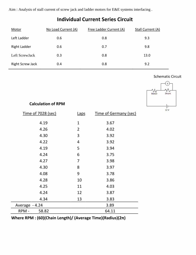
Aim : Analysis of stall current of screw jack and ladder motors for E&E systems interfacing .
Individual Current Series Circuit
Motor No Load Current (A) Free Ladder Current (A) Stall Current (A)
Left Ladder 0.6 0.8 9.3
Right Ladder 0.6 0.7 9.8
Left ScrewJack 0.3 0.8 13.0
Right Screw Jack 0.4 0.8 9.2
Calculation of RPM
Time of 7028 (sec) Laps Time of Germany (sec)
4.19 1 3.67
4.26 2 4.02
4.30 3 3.92
4.22 4 3.92
4.19 5 3.94
4.24 6 3.75
4.27 7 3.98
4.30 8 3.97
4.08 9 3.78
4.28 10 3.86
4.25 11 4.03
4.24 12 3.87
4.34 13 3.83
Average - 4.24 3.89
RPM - 58.82 64.11
Where RPM : (60)(Chain Length)/ (Average Time)(Radius)(2π)