teardown report of one model t53-l-13b...
TRANSCRIPT

TEARDOWN REPORT
TURBOSHAFT ENGINE OF ONE MODEL T53-L-13B
SERIAL NUMBER LE-24073
PS&I:DLL:0122:051200 May 12,2000
Approved By:
Product Safety and Integrity

Honeywell
TEARDOWN REPORT
TURBOSHAFT ENGINE OF ONE MODEL T53-L-13B
SERIAL NUMBER LE-24073
1.0 INTRODUCTION AND SUMMARY
1.1 Pumose
This report presents the findings of a engine examination conducted on a Honeywell International (AlliedSignal/Lycoming) model T53-L- 13B turboshaft engine, serial number LE- 24073, at the Honeywell International Product Safety & Integrity facility in Phoenix, Arizona on February 24 and 25,2000.
The examination was conducted at the request of the National Transportation Safety Board (NTSB), and under the cognizance of the Federal Aviation Administration (FAA).
1.2 Backmound
The engine, serial number LE-24073, was installed in a Bell UH-1H helicopter, registration N853M, serial number 68-16087. The aircraft crashed near Ft. Myers, Florida on January 20, 2000. The NTSB reported that the pilot ‘heard a loud “pop”, the engine fail light illuminated, and engine rpm decayed to zero.’
Summary
The engine damage observed was the result of separation of a section of the second-stage GP turbine disk.
The separation of the section of the second-stage GP turbine disk was due to peak strain low-cycle fatigue. No material defects were identified which would contribute to the separation of the section of the second-stage GP turbine disk.
The service history of the second-stage GP turbine disk could not be determined fiom records provided by the operator.
All other engine damage observed is attributable to the unbalance and structural damage induced by the separation of a section of the second-stage GP turbine disk.
No conditions were observed which would have caused or contributed to the separation of a section of the second-stage GP turbine disk.
PS&I:DLL:O 122:05 1200 1

2.0
2.1
(a)
2.2
(a)
FINDINGS OF T53-L-13B9 SERIAL NUMBER LE-24073
NOTES
1. All references to position are aft looking forward. All references to angular measurements are clockwise.
2. All observations reported herein are based on visual examinations with the unaided eye, unless otherwise noted.
General
The engine was received in a military-style engine shipping container. The engine nameplate (Figure 1) indicated that the engine had been supplied to the U.S. Army under contract DAAJO1-73-D-0036-004 in October, 1974. A Corpus Christi Army Depot (CCAD) overhaul tag was attached to the exterior of the engine inlet (Figure 1). The blocks on the CCAD overhaul tag for ‘Overhaul Date’ and ‘Time Since New’ were marked “/A’.
The gas generating (NG) spool rotated freely. Continuity of the NG spool and NG accessory drive geartrain was verified by rotating the starter drive pad and observing rotation of the compressor, and accessory gearbox tachometer generator output drive shaft.
The power turbine (NP) spool assembly was initially not free to rotate, and metallic fragments were observed visually in the power turbine. After removal of the combustor/turbine module, the power turbine shaft rotated freely. Continuity of the NP spool and NP accessory drive geartrain was verified by rotating the power turbine shaft and observing rotation of the output shaft, and overspeed governor tachometer generator gearbox output drive shaft.
There was no evidence of fire damage (Figure 3). The engine mounts were intact (Figure 3).
Output Reduction Carrier and Gear Assembly
The output reduction gearbox assembly, part number 1-030-350- 12, serial number P908, was undamaged (Figure 4). All planet gears, bearings and the output shaft rotated freely. There was residual oil on all internal surfaces and components of the reduction gearbox.
The reduction gearbox input sun gear was undamaged. The sun gear retaining bolt washer was fractured (Figure 5). There was residual oil on all surfaces of the sun gear retaining bolt washer.
PS&I:DLL:0122:05 1200 2

Honeywell
2.3 Accessory Drive Carrier Assembly
The accessory drive carrier assembly assembly, part number 1-030-350-12, serial number P908, was undamaged (Figure 6) . All gears and bearings rotated freely. There was residual oil on all internal surfaces and components of the reduction gearbox.
2.4 Inlet Housing Assembly
The inlet housing assembly was undamaged (Figure 7). There was residual oil on internal surfaces of the inlet housing.
2.5 Overspeed Governor and Tachometer Drive Assembly
The overspeed governor and tachometer drive assembly (Figure 8), part number 1-1 60- 500-04, serial number not observed, was undamaged and rotated freely. The overspeed governor and tachometer drive assembly driveshaft was undamaged.
2.6 Accessory Drive Gearbox Assembly
The accessory drive gearbox assembly (Figure 9), part number 1-070-220-03, serial The accessory drive gearbox assembly number 248A, was undamaged and rotated freely.
driveshaft was undamaged.
Compressor Section
The variable inlet guide vanes (VIGV) were observed to be in the fully closed position upon receipt of the engine. The VIGV’s rotated freely and in unison when actuated manually using the VIGV connector rod.
The VIGV unison ring was undamaged.
The VIGV connector rod was undamaged and travelled freely.
The NG accessory drive pinion gear was undamaged. There was residual oil on the NG accessory drive pinion gear teeth.
The first-stage axial compressor rotor was intact (Figure 10). There was dirt adhering to the pressure and suction sides of the first-stage compressor rotor blades (Figure 10). Approximately half of the first-stage compressor rotor blade tips displayed rotational scoring (Figure 10). The inter-stage seal land aft of the first-stage axial compressor rotor displayed rotational scoring, through approximately 1 80 degrees, with corresponding rotational score marks on the first-stage axial compressor stator forward ID vane platform.
The second-stage axial compressor rotor was intact (Figure 10). There was dirt adhering to the pressure and suction sides of the second-stage compressor rotor blades (Figures 10 and 11). Approximately half of the second-stage compressor rotor blade tips displayed rotational scoring and material accumulation on both pressure and suction sides (Figures
PS&I:DLL:0122:05 1200 3

Honeywell
10 and 11). The inter-stage seal land forward of the second-stage axial compressor rotor displayed rotational scoring, through approximately 180 degrees, adjacent to the aft ID vane platform on the first-stage axial compressor rotor stator (Figure l l ) , with corresponding rotational score marks on the aft ID vane platform on the first-stage axial compressor rotor stator. The inter-stage seal land aft of the second-stage axial compressor rotor displayed rotational scoring, through approximately 180 degrees, with corresponding rotational score marks on the forward ID vane platform on the second- stage axial compressor rotor stator.
The third-stage axial compressor rotor was intact (Figure 10). There was dirt adhering to the pressure and suction sides of the third-stage compressor rotor blades (Figures 10 and 11). Approximately half of the third-stage compressor rotor blade tips displayed rotational scoring and material accumulation on both pressure and suction sides (Figures 10 and 11). The inter-stage seal land forward of the third-stage axial compressor rotor displayed rotational scoring, through approximately 180 degrees, with corresponding rotational score marks on the aft ID vane platform on the second-stage axial compressor rotor stator. The inter-stage seal land aft of the third-stage axial compressor rotor displayed rotational scoring, through approximately 180 degrees, with corresponding rotational score marks on the forward ID vane platform on the third-stage axial compressor rotor stator.
The fourth-stage axial compressor rotor was intact (Figure 10). There was dirt adhering to the pressure and suction sides of the fourth-stage compressor rotor blades (Figures 10 and 1 I). Approximately half of the fourth-stage compressor rotor blade tips displayed rotational scoring and material accumulation on both pressure and suction sides (Figures 10 and 11). The inter-stage seal land forward of the fourth-stage axial compressor rotor displayed rotational scoring, through approximately 180 degrees, with corresponding rotational score marks on the aft ID vane platform on the third-stage axial compressor rotor stator. The inter-stage seal land aft of the fourth-stage axial compressor rotor displayed rotational scoring, through approximately 1 80 degrees, with corresponding rotational score marks on the forward ID vane platform on the fourth-stage axial compressor rotor stator.
The fifth-stage axial compressor rotor was intact (Figure 10). There was dirt adhering to the pressure and suction sides of the fifth-stage compressor rotor blades (Figures 10 and 11). Approximately half of the fifth-stage compressor rotor blade tips displayed rotational scoring and material accumulation on both pressure and suction sides (Figures 10 and 11). The inter-stage seal land forward of the fifth-stage axial compressor rotor displayed rotational scoring, through approximately 180 degrees, with corresponding rotational score marks on the aft ID vane platform on the fourth-stage axial compressor rotor stator. The inter-stage seal land aft of the fifth-stage axial compressor rotor displayed rotational scoring, through approximately 180 degrees, with corresponding rotational score marks on the forward ID vane platform on the compressor exit guide vane.
PS&I:DLL:O 122:05 I200 4

Honeywell
The first-stage axial compressor rotor stator was intact (Figure 12). There was dirt adhering to the pressure and suction sides of the first-stage axial compressor rotor stator vanes (Figure 12). The forward and aft ID vane platforms of the first-stage axial compressor rotor stator displayed rotational scoring, with corresponding rotational score marks on the inter-stage seal land aft of the first-stage axial compressor rotor and the inter-stage seal land forward of the second-stage axial compressor rotor.
The second-stage axial compressor rotor stator was intact (Figure 12). There was dirt adhering to the pressure and suction sides of the second-stage axial compressor rotor stator vanes (Figure 12). The forward and aft ID vane platforms of the second-stage axial compressor rotor stator displayed rotational scoring, with corresponding rotational score marks on the inter-stage seal land aft of the second-stage axial compressor rotor and the inter-stage seal land forward of the third-stage axial compressor rotor.
The third-stage axial compressor rotor stator was intact (Figure 12). There was dirt adhering to the pressure and suction sides of the third-stage axial compressor rotor stator vanes (Figure 12). The forward and aft ID vane platforms of the third-stage axial compressor rotor stator displayed rotational scoring, with corresponding rotational score marks on the inter-stage seal land aft of the third-stage axial compressor rotor and the inter-stage seal land forward of the fourth-stage axial compressor rotor.
The fourth-stage axial compressor rotor stator was intact (Figure 12). There was dirt adhering to the pressure and suction sides of the fourth-stage axial compressor rotor stator vanes (Figure 12). The forward and aft ID vane platforms of the fourth-stage axial compressor rotor stator displayed rotational scoring, with corresponding rotational score marks on the inter-stage seal land aft of the fourth-stage axial compressor rotor and the inter-stage seal land forward of the fifth-stage axial compressor rotor.
The compressor exit guide vanes were intact (Figure 12). There was dirt adhering to the pressure and suction sides of the compressor exit guide vanes (Figure 12). The forward and aft ID vane platforms of the compressor exit guide vanes displayed rotational scoring, with corresponding rotational score marks on the inter-stage seal land aft of the fifth- stage axial compressor rotor.
The upper axial compressor housing was intact (Figures 13 and 14). The lower axial compressor housing was intact, and was not removed for examination.
The centrifugal compressor was intact (Figure 1 9 , and was not removed for examination. The inlet and transition shroud-line edge of approximately half of the blades of the centrifugal compressor displayed rotational scoring and material accumulation on both pressure and suction sides (Figure 15), with corresponding rotational score marks on the adjacent surfaces of the centrifugal compressor shroud.
The upper centrifugal compressor shroud was intact (Figure 16). The upper centrifugal compressor shroud displayed rotational scoring through approximately 1 80 degrees on surfaces adjacent to inlet and transition shroud-line edges of the centrifugal compressor
PS&I:DLL:0122:051200 5

Honeywell
blades (Figure 16), with corresponding rotational score marks on the inlet and transition shroud-line edges of the centrifugal compressor blades. The lower centrifugal compressor shroud was intact, and was not removed for examination.
Combustor Section
The 1 and 11 o’clock ignitor plugs were intact (Figure 17). There was fretting on the surfaces of both ignitor plugs at the combustion chamber interface (Figure 17). There was carbon on the tips and electrodes of both ignitor plugs (Figure 17). The electrodes of both ignitor plugs were eroded (Figure 17).
The 4 and 8 o’clock ignitor plugs were intact (Figure 18). There was fretting on the surfaces of both ignitor plugs at the combustion chamber interface (Figure 18). There was carbon on the tips and electrodes of both ignitor plugs (Figure 18). The electrodes of both ignitor plugs were eroded (Figure 18).
The combustor drain valve appeared to be undamaged, but was not removed for inspection.
The combustion chamber liner was intact (Figure 19). There were carbon deposits on external (Figure 19) and internal surfaces of the combustion chamber liner dome. There was an outward puncture through the combustion chamber liner inner wall (Figure 20) and outer wall (Figure 21) at approximately 8 o’clock.
The combustion chamber plenum was intact (Figure 22). There was an outward bulge in the combustion chamber plenum wall at approximately 8 o’clock (Figure 23).
The combustion chamber outer curl appeared to be intact (Figure 24), but was not removed for examination. There was metallic debris in the dished area of the combustion chamber outer curl (Figure 24).
The diffuser housing appeared to be undamaged, but was not removed for examination.
The v-band clamp securing the exhaust diffuser support cone assembly was undamaged.
The exhaust diffuser support cone assembly was intact (Figure 25). There was corrosion on external surfaces of the exhaust diffuser support cone assembly.
The exhaust diffuser assembly was intact (Figure 26). The exhaust diffuser struts were intact. The exhaust diffuser strut at 12 o’clock was damaged (Figure 27).
The fire shield was undamaged (Figure 28).
The start fuel nozzles were intact (Figure 29) and appeared to undamaged, but were not functionally tested. There were carbon deposits on the start fuel nozzle tips (Figure 29). Portions of the gaskets under the start fuel nozzles had separated and were missing (Figure 30).
PS&I:DLL:O 122:05 1200 6

Honeywell
The right and left fuel manifold assemblies were intact (Figures 31 and 32) and appeared to undamaged, but were not functionally tested. There were carbon deposits on the right and left fuel manifold assembly fuel injector air shrouds (Figure 33).
Gas Producer (GP) Turbine Section
The first-stage GP turbine nozzle was intact (Figure 34), but was not removed from the engine due to the severe corrosion of the retaining bolts (Figure 35). The trailing edges of several first-stage GP turbine nozzle vanes were fractured and deflected forward (Figure 36). There was a rub, with what appeared to be oxidation covering the rub, over 360 degrees, on the first-stage turbine rotor shroud (Figure 37). Several bolts securing the second-stage GP turbine cylinder to the first-stage GP turbine nozzle were found to be fractured (Figures 35,36 and 37).
The first-stage GP turbine rotor was intact (Figure 38). There was rotational scoring, with what appeared to be oxidation covering the score marks on the tips of all first-stage GP turbine rotor (Figures 39 and 40). There were nicks and dents on the trailing edges of the first-stage GP turbine rotor blades (Figure 40).
The second-stage GP turbine nozzle was heavily damaged (Figures 41 and 42). The leading edges of the second-stage GP turbine nozzle vanes were cracked (Figure 43). The trailing edges of the second-stage GP turbine nozzle vanes were deformed and fiactured (Figure 44). Sections of the trailing edges of the second-stage GP turbine nozzle vanes were missing (Figures 42 and 44). There was rotational scoring, over 360 degrees, on the aft face of the second-stage GP turbine nozzle inner support (Figures 42 and 44). Sections of the aft face of the second-stage GP turbine nozzle inner support were missing (Figures 42 and 44). The second-stage GP turbine rotor shroud was scored and deformed (Figures 42 and 44). Sections of the aft face of the second-stage GP turbine nozzle outer support were missing (Figures 42 and 44).
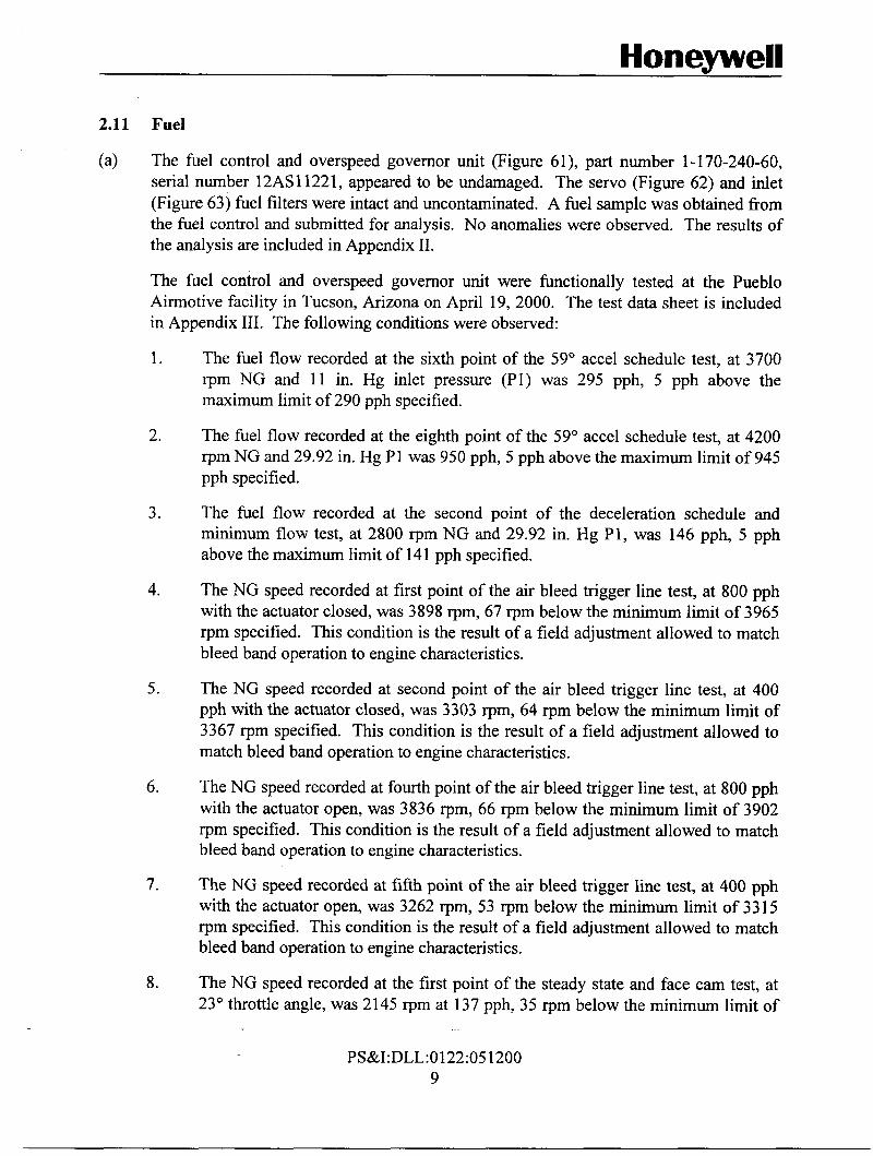
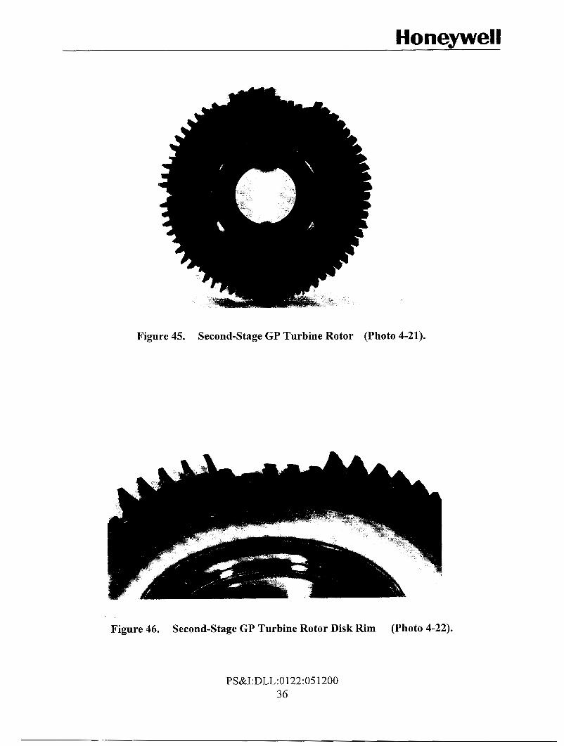
The second-stage GP turbine rotor assembly (Figure 45) was identified as part number 1- 10 1-360-04, serial number 5 15. The second-stage GP turbine rotor disk was identified as part number 1-100-063-05, serial number 515, manufacturer code LE-72. A portion of the second-stage GP turbine rotor disk rim had separated (Figures 45 and 46). Six second-stage GP turbine rotor blades were missing (Figures 45 and 46). The remaining second-stage GP turbine rotor blades were fi-actured at approximately mid-span (Figures 45,46 and 47).
The second-stage GP turbine rotor assembly was submitted for Material Analysis (MA) to determine the reason for the separation of a portion of the second-stage GP turbine rotor disk rim. The results of the MA indicate that the fracture of the second-stage GP turbine rotor assembly was due to peak strain low-cycle fatigue (LCF). No material defects were identified which would contribute to the separation of the section of the second-stage GP turbine disk. The MA is included in Appendix I.
PS&I:DLL:0122:051200 7

Honeywell
The GP spool aft nut was intact (Figure 48) and the lock cup properly secured. The break-away torque of the aft nut was approximately 50 ft-lb.
The forward and aft GP turbine cones were intact (Figure 49). The aft GP cone displayed uneven serration patterns corresponding to the aft spline on the GP shaft. The aft GP turbine cone was submitted for MA to determine the reason for the uneven serration pattern. The MA is included in Appendix I.
Power Turbine
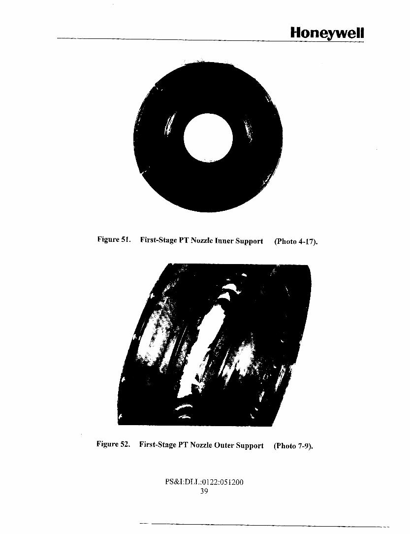
The first-stage PT nozzle was heavily damaged (Figures 50 and 5 1). All of the first-stage PT nozzle vanes had separated and were missing (Figures 50 and 51). There was rotational scoring, over 360 degrees, on the inner diameter of the first-stage PT nozzle outer support (Figures 50 and 52). There was an outward puncture of the outer support approximately three inches in length (Figure 52). The first-stage PT nozzle inner support was cracked in four places (Figure 51). There was rotational scoring, over 360 degrees, on the forward face of the first-stage PT nozzle inner support (Figure 5 1).
The first-stage PT rotor (Figure 53) was identified as part number 1-190-010-02, serial number 24273, CAGE code 91547. The leading edges and tips of all first-stage PT rotor blades were battered, and sections of all blades were missing (Figure 53). Five of the first-stage PT rotor blades were fractured near the disk OD and had separated (Figures 53 and 54).
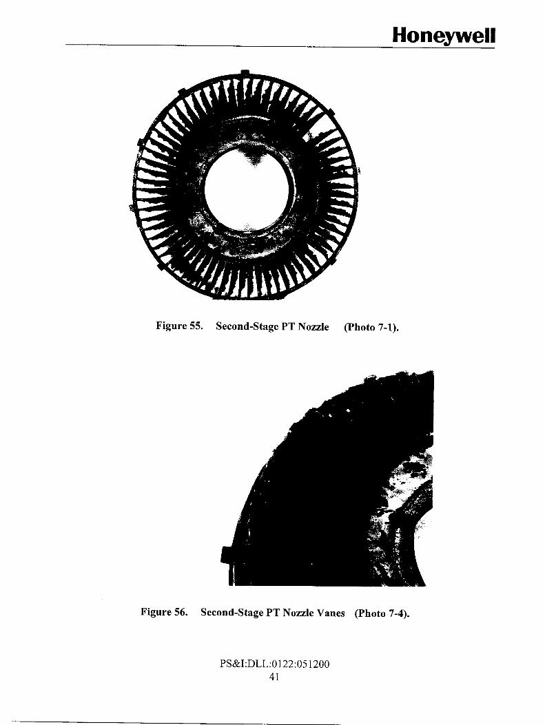
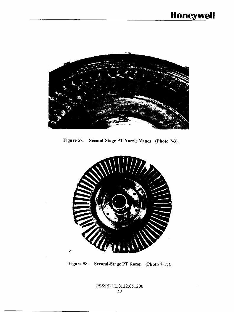
The second-stage PT nozzle was heavily damaged (Figure 55). One of the second-stage PT nozzle vanes was missing (Figure 55). The leading edges of all second-stage PT nozzle vanes were battered and dented (Figures 55 and 56). The trailing edges of all second-stage PT nozzle vanes were battered and dented (Figures 56 and 57). Sections of the trailing edges of all second-stage PT nozzle vanes had separated and were missing (Figures 55 and 57).
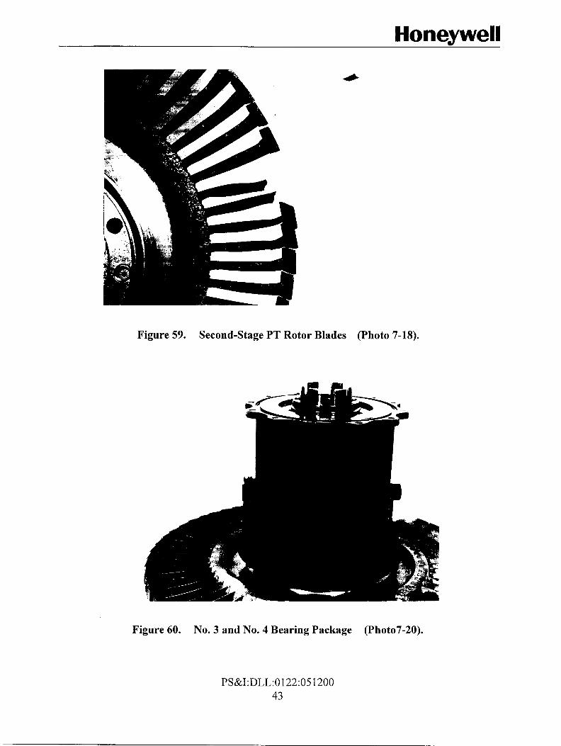
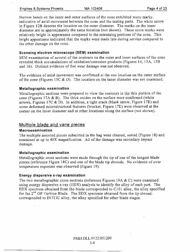
The second-stage PT rotor (Figure 58) was identified as part number 1 - 140-550-07, serial number 000078. The leading edges of all second-stage PT rotor blades were battered, and sections of five blades were missing (Figures 58 and 59). There were cracks on the trailing edges of several second-stage PT rotor blades (Figure 59).
The No. 3 (roller) and No. 4 (ball) bearing housing was intact (Figure 60) and appeared to be undamaged, but was not disassembled for inspection. The bearing housing rotated freely, and there was residual oil on internal surfaces of the bearing housing. There were soot and carbon deposits on external surfaces of the bearing housing (Figure 60). The heat shield enclosing the bearing housing was corroded, and the aft section of the heat shield had separated and was missing (Figure 60).
PS&I:DLL:0122:05 1200 8
Honeywell
2.11 Fuel
(a) The fuel control and overspeed governor unit (Figure 61), part number 1-170-240-60, serial number 12AS11221, appeared to be undamaged. The servo (Figure 62) and inlet (Figure 63) fuel filters were intact and uncontaminated. A fuel sample was obtained from the fuel control and submitted for analysis. No anomalies were observed. The results of the analysis are included in Appendix 11.
The fuel control and overspeed governor unit were functionally tested at the Pueblo Airmotive facility in Tucson, Arizona on April 19, 2000. The test data sheet is included in Appendix 111. The following conditions were observed:
1. The fuel flow recorded at the sixth point of the 59" accel schedule test, at 3700 rpm NG and 11 in. Hg inlet pressure (Pl) was 295 pph, 5 pph above the maximum limit of 290 pph specified.
2. The fuel flow recorded at the eighth point of the 59" accel schedule test, at 4200 rpm NG and 29.92 in. Hg P1 was 950 pph, 5 pph above the maximum limit of 945 pph specified.
3. The fuel flow recorded at the second point of the deceleration schedule and minimum flow test, at 2800 rpm NG and 29.92 in. Hg P1, was 146 pph, 5 pph above the maximum limit of 141 pph specified.
4. The NG speed recorded at first point of the air bleed trigger line test, at 800 pph with the actuator closed, was 3898 rpm, 67 rpm below the minimum limit of 3965 rpm specified. This condition is the result of a field adjustment allowed to match bleed band operation to engine characteristics.
5 . The NG speed recorded at second point of the air bleed trigger line test, at 400 pph with the actuator closed, was 3303 rpm, 64 rpm below the minimum limit of 3367 rpm specified. This condition is the result of a field adjustment allowed to match bleed band operation to engine characteristics.
6. The NG speed recorded at fourth point of the air bleed trigger line test, at 800 pph with the actuator open, was 3836 rpm, 66 rpm below the minimum limit of 3902 rpm specified. This condition is the result of a field adjustment allowed to match bleed band operation to engine characteristics.
7. The NG speed recorded at fifth point of the air bleed trigger line test, at 400 pph with the actuator open, was 3262 rpm, 53 rpm below the minimum limit of 33 15 rpm specified. This condition is the result of a field adjustment allowed to match bleed band operation to engine characteristics.
8. The NG speed recorded at the first point of the steady state and face cam test, at 23" throttle angle, was 2145 rpm at 137 pph, 35 rpm below the minimum limit of
PS&I:DLL:O 122:05 1200 9

Honeywell
21 80 rpm specified. This condition is the result of a field adjustment allowed to adjust fuel flow to engine characteristics.
9. The NG speed recorded at the third point of the steady state and face cam test, at 38" throttle angle, was 2843 rpm at 210 pph, 47 rpm below the minimum limit of 2890 rpm specified. This condition is the result of a field adjustment allowed to adjust fuel flow to engine characteristics.
10. The NG speed recorded at the fifth point of the steady state and face cam test, at 100" throttle angle, was 4320 rpm at 800 pph, 21 rpm above the maximum limit of 4299 rpm specified. This condition is the result of a field adjustment allowed to adjust fuel flow to engine characteristics.
The flow divider and dump valve (Figure 64) appeared to be undamaged, but was not functionally tested. There was corrosion on external surfaces of the flow divider and dump valve. No component identification markings were observed.
The start solenoid valve (Figure 65), part number 1-300-1 91-05, serial number G07485, appeared to be undamaged, but was not functionally tested. The attaching ears of the start solenoid valve were fractured (Figure 65).
The VIGV actuator (Figure 66), part number 1- 1 SO- 150-0 1, serial number 68, appeared to be undamaged, but was not functionally tested.
Oil
The oil pump (Figure 67), part number 1-300-212-04, serial number C8168, appeared to be undamaged, but was not functionally tested. There was residual oil within the oil pump. The oil pump rotated freely when the drive shaft was manually rotated, and pumping and scavenge operation was observed when the oil pump was rotated.
The oil filter was intact and uncontaminated (Figure 68). The oil filter was submitted for backflush and analysis. The filter backflush showed that 6 milligrams of contaminants were present in the filter, consisting mostly of dirt and fibers, with trace amounts of silver and iron. The results of the analysis are included in Appendix 11.
The magnetic chip detector was intact and uncontaminated (Figure 69).
The accessory gearbox oil strainer (Figure 70) and rear turbine oil screen (Figure 71) were intact and uncontaminated.
During disassembly the rear turbine oil scavenge fitting (Figure 72) was observed to be hand tight.
An oil sample was obtained from the air inlet housing and submitted for analysis. 13 ppm of iron was detected during SOAP analysis. The results of the analysis are included in Appendix 11.
PS&I:DLL:0122:05 1200 10

Honeywell
Pneumatic
The hot air valve, serial number 6031434 appeared to be undamaged, but was not functionally tested (Figure 73). No component part number was observed.
The bleed band actuator, part number 1-170-050-12, serial number X347 appeared to be undamaged, but was not functionally tested (Figure 74).
Electrical
The ignition exciter, Unison part number 10-383225-1, serial number not observed, appeared to be undamaged, but was not functionally tested (Figure 75).
The ignition leads appeared to be undamaged, but were not functionally tested (Figure 76).
The exhaust gas temperature thermocouple harness was marked as part number ‘ 8 1996/1- 300-1 77-4V’, ‘MFR 24733’, NSN 1680-00-732-0636,, serial number 107023, appeared to be undamaged (Figure 77). The exhaust gas temperature thermocouple harness was functionally tested. Functional test results demonstrate that the exhaust gas temperature thermocouple harness was capable of providing an accurate signal representing the exhaust gas temperature. The results of the functional test are included in Appendix 111.
PS&I:DLL:0122:051200 11
Honeywell
3.0 Analvsis and Conclusions
3.1 Analvsis
The turbine damage observed was initiated by separation of a section of the second-stage GP turbine disk due to peak strain low-cycle fatigue.
Separation of the section of the second-stage GP turbine disk resulted in liberation of disk and blade fragments which caused lesser secondary damage to the upstream second-stage GP turbine nozzle, first-stage GP turbine rotor, and first-stage GP turbine nozzle, and more extensive secondary damage to the downstream first-stage PT nozzle, first-stage PT rotor, and second-stage PT nozzle and rotor.
Separation of the section of the second-stage GP turbine disk resulted in significant imbalance of the GP spool, which caused the interference of the axial and centrifugal compressor stages with the respective shrouds. The interference of the axial and centrifugal compressor stages with the respective shrouds resulted in the tip rubs observed on the first- through fifth- stage axial compressor blades, and the centrifugal compressor blades.
Imbalance of the GP spool, or the initial imbalance load caused by separation of the section of the second-stage GP turbine disk, resulted in relative movement between the aft GP turbine cone and the GP spool. This relative movement resulted in interference of the aft GP turbine cone with the aft internal splines of the GP spool, and the impressions observed on the aft GP turbine cone, and the fracture of the sun gear retaining bolt washer.
No material defects were identified which would contribute to the separation of the section of the second-stage GP turbine disk. The service history of the second-stage GP turbine disk could not be determined from records provided by the operator.
Qualitative bearing evaluation and freedom of the oil filter and magnetic chip detector from metallic particles suggests that a lubrication related bearing degradation and resulting vibration did not contribute to the separation of the section of the second-stage GP turbine disk.
Functional testing of the fuel control demonstrated that the fuel control and overspeed governor were operable. The fuel control had been adjusted to accommodate engine characteristics, resulting in conditions observed which did not meet functional test specifications. No fuel control conditions were identified which would have prevented satisfactory engine operation, or contributed to separation of a section of the second-stage GP turbine disk.
3.2 Conclusions
(a) The engine damage observed was the result of separation of a section of the second-stage GP turbine disk.
PS&I:DLL:0122:05 1200 12

Honeywell
(b) The separation of the section of the second-stage GP turbine disk was due to peak strain low-cycle fatigue. No material defects were identified which would contribute to the separation of the section of the second-stage GP turbine disk.
(c) The service history of the second-stage GP turbine disk could not be determined from records provided by the operator.
(d) All other engine damage observed is attributable to the unbalance and structural damage induced by the separation of a section of the second-stage GP turbine disk.
(e) No conditions were observed which would have caused or contributed to the separation of a section of the second-stage GP turbine disk.
PS&I:DLL:0122:051200 13

P I ooz I so : 22 I 0: ??a:IVsd

Hone-well
Figure 35. First-Stage GP Turbine Nozzle Bolts (Photo 6-8).
Figure 36. First-Stage GP Turbine Nozzle Bolts (Photo 6-13).
PS&I:DLL:0122:051200 31

Honeywell
Figure 43. Second-Stage GP Turbine Nozzle Vanes (Photo 5-9).
Figure 44. Second-Stage GP Turbine Nozzle Vanes (Photo 5-12).
PS&I:DLL:O 122:05 1200 35
Honeywell
Figure 45. Second-Stage GP Turbine Rotor (Photo 4-21).
Figure 46. Second-Stage GP Turbine Rotor Disk Rim (Photo 4-22).
PS&I:DLL:0122:051200 36
Honeywell
Figure 51. First-Stage PT Nozzle Inner Support (Photo 4-17).
Figure 52. First-Stage PT Nozzle Outer Support (Photo 7-9).
PS&I:DLL:0122:05 1200 39

Honeywell
Figure 53. First-Stage PT Rotor (Photo 5-31).
Figure 54. First-Stage PT Rotor Blades (Photo 5-32).
PS&I:DLL:O122:05 1200 40
Honeywell
Figure 55. Second-Stage PT Nozzle (Photo 7-1).
Figure 56. Second-Stage PT Nozzle Vanes (Photo 7-4).
PS&I:DLL:O 122:05 1200 41
Honeywell
Figure 57. Second-Stage PT Nozzle Vanes (Photo 7-3).
Figure 58. Second-Stage PT Rotor (Photo 7-17).
PS&I:DLL:0122:05 1200 42
Hone-well
Figure 59. Second-Stage PT Rotor Blades (Photo 7-18).
Figure 60. No. 3 and No. 4 Bearing Package (Photo7-20).
PS&I:DLL:0122:051200 43

Honeywell I
I COMPONENT INVESTIGATIONS Engines & Systems PRELIMINARY MATERIALS ANALYSIS 102406 - For Internal Use Only - Phoenix Page 1 of 23
UESTER D. Looper PHONE 365-2365 CHARGE NO. 4009-2 1224 DATE 03/02/00 T NAME 2nd GP Turb. Rotor AssyICone Rear compressor PART NO. 1 - 10 1 -360-04/1- 1 10-1 4 1-0 1 PART SIN 5 15 ERIAL D979/aluminurn bronze/C 10 1 MAT'L SPEC M3603lAMS4640lM36 17 SUPPLIER Not Reported IP~ENGINE T53-L-13B EQUIP SIN LE-24073 OPERATING TIMEICYCLES Reportedly 962 TSO
IITIONAL INFORMATION
irbiiie Rotor assembly and aft cone removed from engine following aircraft accident on 1/20/00 near Ft. Myers, Florida. igine records indicate 962 hours since overhaul, cycles unknown, total time unknown. verhaul nameplate indicates CCAD overhaul, however CCAD has no record of overhaul work on this engine .igine was run at CCAD test cell on 4/8/93. Engine build records being pulled. iarkings on Disk: MFR LE72, S/N 5 15,9 1547, 1 - 100-360-04 (corrected to 1- 10 1 -360-04), RCVOR S/N 5 1 5
isk P/N 1-100-063-05 & Blade P/N 1-100-1 18-07. I54711 - 100-063-05L.
3BLEM STATEMENT
iocument rotor and cone. Determine nature of fracture of rotor. xamine aft cone and determine if evidence of vibration is present.
MMARY/CONCLUSION(S)
'he primary separation of the 2"d GP Turbine Rotor was the result of Sustained Peak Strain Low Cycle Fatigue. Three of the disk post separation fractures and the exposed fractures of two pin slot cracks exhibited similar heavily oxidized intergranular features. Evidence of fracture progression was observed as variations in the surface oxide. These features are typically associated with Sustained Peak Strain Low Cycle Fatigue. The fourth disk post separation was the result of secondary overload.
'he Rear Compressor Cone exhibited thick oxides on the surface and evidence of deformation. Evidence of fret wear was not detected.
~ESTIGATOR F. Krempski REVIEWER /f*& .- DATE sb!/& REVIEWER J. Gour'ey DATE 'OF
I NAME OF PART PART NO. MATERIAL PART CONDITION IISTRIBUTION DEPT MIS >. Looper 72-20 2 102- 12 1 . Hanenburg 93-23 404-282 VI. Morgan ' . 93-23 404-282 2. Henry 93-64 404-257 vi. Woodhall 93-32 404-287 '. GourleylR. Sines (2) 93-33 301-227
2"d GP Turb. Disk 1 - 100-063-05 D979 FA SPS Low Cyc Cone, aft 1-1 10-141-01 Aluminum bronze OT deform. crack 2"d GP Turb. Blade 1-100-1 18-07 ClOl DO no OT
PRELIMINARY RESULTS REPORTED TO: Distribution DATE: 03/17/00
REFERENCES No similar previous MAS.
PS&I:DLL:0122:051200 I- 1

Engines & Systems Phoenix MA 102406 Page 2 of 23
Overview Three “sets” of hardware were submitted for analysis. 0
0 The Rear Compressor Cone. 0
The 2”d GP Turbine Rotor with remnants of all but six of the blades still attached.
A bag of multiple blade and vane pieces.
The results will be reported for each set of hardware in the order listed above.
2nd GP Turbine Rotor Macroexamination The rotor exhibited uniform separations of all of the attached blades at a height of approximately 0.2-inch to approximately 0.4-inch outboard of the disk rim (Figure I A). The fractures were indicative of impact overload and were the result of secondary damage (not shown).
The firtree slots of two of the six missing blades exhibited evidence of deformation on the firtree dovetails at the forward side of the slot (not shown). One slot exhibited approximately 0.15” of deformation and the other slot exhibited approximately 0.35” of dovetail deformation. The locking pins in both slots were fractured in shear. Several other attached blades were displaced forward on the disk rim. These blade separations were also believed to be secondary damage.
The rotor exhibited separations of the forward side of four adjacent posts (tenons) as shown in Figures 1A & B. Two fractures initiated at the sharp corners of the same pin slot (thick white arrows, Figures 2A, 3A & 3B). Both fractures were heavily oxidized and coated with dirt and debris. Close examination revealed intergranular fracture features with some evidence of fracture progression indicated by differences in oxidation (black arrows, Figures 3A & B).
The intergranular appearing portions of these two adjacent fractures were similar in size measuring approximately:
0
0
0.2-inch along both of the pin slots, 0.3-inch at the center of the fracture and 0.26-inch along the forward face.
The remaining portions of the post separation fractures were the result of overload (brackets, Figures 3A & B). This portion of the fracture was also discolored due to oxidation.
The one partial fracture, although smaller, exhibited similar intergranular features and initiated at the corner of the pin slot (arrow, Figure 3C). The third fracture was the result of overload (Figure 3D).
Additional similar appearing cracks were observed emanating from the corners of eight other pin slots (reference black arrows, Figure 1A). Some pin slots exhibited only one crack (Figures 4C & D) and others exhibited two (Figures 4A, 4B, 5A & 5C).
PS&I:DLL:0122:05 1200 1-3

Page 3 of 23 Engines & Systems Phoenix MA I02406
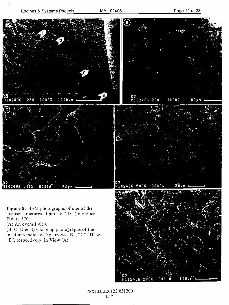
Two cracks emanating from the corners of pin slot "D" (Figures 5A & C) that was situated approximately 180" opposite the separation fractures (reference Figure 1 A) were exposed for examination. These fractures were also heavily oxidized and intergranular in appearance (Figures 5B & D). These two fractures were measured to be approximately:
1. 0.12-inch in the pin hole & 0.14-inch on the forward face. 2. 0.15-inch along the pin hole (including the tunneled portion) & 0.1 1-inch on the
forward face.
Macrohardness test results The hardness of the disk was measured on the forward hub rim and on the forward post endface to be 71HRA and 71HRA, respectively. Specified was 69HRA to 73HRA.
Scanning electron microscope examination One of the separation fractures (Figures 6 & 7) and both of the exposed fractures were examined using the scanning electron microscope (SEM). The fractures all exhibited intergranular features. Intergranular features and heavy oxides were evident near the origins (Figures 6B, 6C, 8B & 9B). The extent of oxidation decreased with increased distance from the origins (Figures 6A, 7A, 7B, 7C, 8C, 8D, 8E, 9C & 9D).
Metallographic examination A metallographic section was prepared to view one separation fracture by lightly grinding and polishing parallel to the pin slot into the side of the fracture with the fatigue origin (Figures 10 & 11A).
The fracture was primarily intergranular with some scattered clusters of transgranular fractures. The fracture features were very heavily oxidized near the fatigue origin (white arrows, Figure 1 OA). The oxidation products on the fracture surface decreased with distance from the origin (Figures 1OC & D) and some of the intergranular cracks exhibited heavy oxidation products (arrow, Figure 1 OC). The grain boundaries in the cross section exhibited heavy precipitation (Figure 1 1).
The grain size on the aft side of the platform was distinctly smaller than in the remaining portion of the cross section. The grain size within the aft disk rim (Figure 11C) was measured to be ASTM 8 and the grain size within the for'ward disk and rim was measured to be ASTM 7 (Figure 1 IB). This variation in grain size was believed to be from the forging.
The Rear Compressor Cone Macroexam ination The cone was relatively dark in appearance with a dull gray color. The thin portion of the cone exhibited distinct contours on the outer and inner surfaces indicative of close contact with the mating parts. The outer cone-shaped surface exhibited contours suggestive of the ends of a spline (Figure 12A & B). These contours were not uniform around the entire circumference. One approximately 180' segment (Figures 12 and 13A) exhibited much more pronounced contours than the opposite 180" segment (Figures 13B & E). The more pronounced contours exhibited features suggesting that the contours were the result of deformation of the part (Figures 12 and 13A).
PS&I:DLL:0122:05 1200 1-3
Engines & Systems Phoenix MA 102406 Page 4 of 23
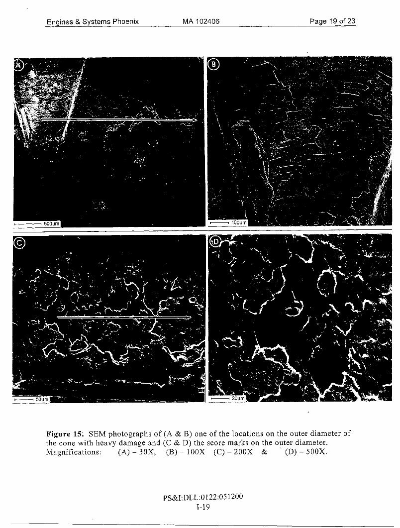
Narrow bands on the inner and outer surfaces of the cone exhibited score marks indicative of axial movement between the cone and the mating parts. The white arrow in Figure 12B denotes the location on the outer diameter. The marks on the inner diameter are in approximately the same location (not shown). These score marks were relatively bright in appearance compared to the remaining portions of the cone. This bright appearance indicated that the marks were made late during service compared to the other damage on the cone.
Scanning electron microscope (SEM) examination SEM examination of several of the contours on the outer and inner surfaces of the cone revealed thick accumulations of oxidation/corrosion products (Figures 14, 15A, 15B and 16). Distinct evidence of fret wear damage was not observed.
The evidence of axial movement was confirmed at the one location on the outer surface of the cone (Figures 15C & D). The location on the inner diameter was not examined.
Metallographic examination Metallographic sections were prepared to view the contours in the thin portion of the cone (Figures 17A & B). The thick oxides on the surface were confirmed (white arrows, Figures 17C & D). In addition, a tight crack (black arrow, Figure 17E) and some deformed microstructural features (bracket, Figure 17E) were observed at the corner on the inner diameter and at other locations along the surface (not shown).
Multiple blade and vane pieces Macroexamination The multiple assorted pieces submitted in the bag were cleaned, sorted (Figure 18) and examined at up to 40X magnification. All of the damage was secondary impact damage.
Metallographic examination Metallographic cross sections were made through the tip of one of the longest blade pieces (reference Figure 18C) and one of the blade tip shrouds. No evidence of over temperature exposure was observed (Figure 19).
Energy dispersive x-ray examination The two metallographic cross sections (reference Figures 19A & C) were examined using energy dispersive x-ray (EDX) analysis to identify the alloy of each part. The EDX spectrum obtained from the blade corresponded to C 10 1 alloy, the alloy specified for the 2"d GP Turbine Blade. The EDX spectrum obtained from the tip shroud. corresponded to IN7 13C alloy, the alloy specified for other blade stages.
PS&I:DLL:O 122:05 1200 1-4
Engines & Systems Phoenix MA 102406 Page 5 of 23
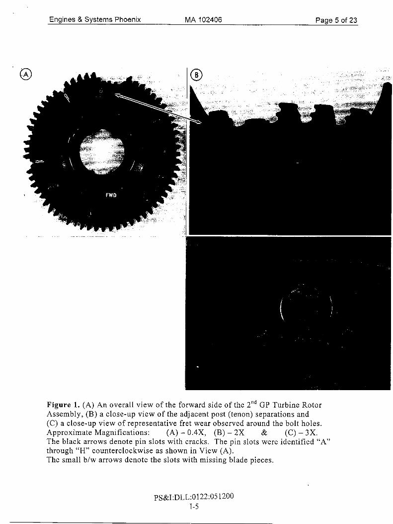
Figure 1. (A) An overall view of the forward side of the 2”d GP Turbine Rotor Assembly, (B) a close-up view of the adjacent post (tenon) separations and (C) a close-up view of representative fret wear observed around the bolt holes. Approximate Magnifications: (A) - 0.4X, (B) - 2X & (C) - 3X. The black arrows denote pin slots with cracks. The pin slots were identified “A” through “H” counterclockwise as shown in View (A). The small b/w arrows denote the slots with missing blade pieces.
P S&I :DLL : 0 122:05 1200 1-5

Engines & Systems Phoenix MA 102406 Page 6 of 23
+d
H $ tr Figure 2. Views. of the adjacent pin slots showing (A) two primary .fracture origins (thick white arrows), two sec0ndar.y fracture
origins (thin white arrows) and (C) two overload fractures on the outboard side of each of the pin slots. H . . 6\ 2 Approximate Magnifications: All - 15X.
R,
0 wl R, 0 0
!? L

Engines & Systems Phoenix MA 102406 Page 7 of 23
Figure 3. Views of the adjacent post fractures that initiated at the pin slots showing (A & B) the two primary fractures and their origins (thick white arrows) and one small secondary fracture origin (thin white arrow), (C) a secondary fracture and origin (thin white arrow) and (D) an overload fracture. Approximate Magnifications: All - 1OX.
, . ..
c( b .. & 2
The black arrows denote differences in oxidation indicative of fracture progression. The black brackets denote the overload portions of the fractures.
N .. N 0 wl N 0 0
w

Engines & Systems Phoenix MA 102406 . Page8of23
Figure 4. Views of representativ.e cracks (arrows) emanating from the corners of pin slots. (A & B) The cracks on the outboard side of pin slot “H” as identified in Figure 1A. (C & D)’The cracks on the outboard sides of pin slots “G” & “E”, respectively, as identified in Figure 1A. Approximate Magnifications: (A, B & D) - 30X & (C) - 15X.
PS&I:DLL:0122:05 i‘200 1-8

Engines & Systems Phoenix MA 102406 Page 9 of 23
Figure 5. Views of the cracks and laboratory exposed fractures emanating from the corners on the outboard side of pin slot “D” as identified in Figure IA.
The brackets in Views (B & D) denote the pin slot. Note that the origins are not shown balanced around the pin slot because one fracture is the inboard side of the fracture and the other is the outboard side.
Approximate Magnifications: (A & C) - 30X & (B &D)-2OX.
PS&I:DLL:O 122:05 1200 1-9
Engines & Systems Phoenix MA 102406 Page 10 of 23
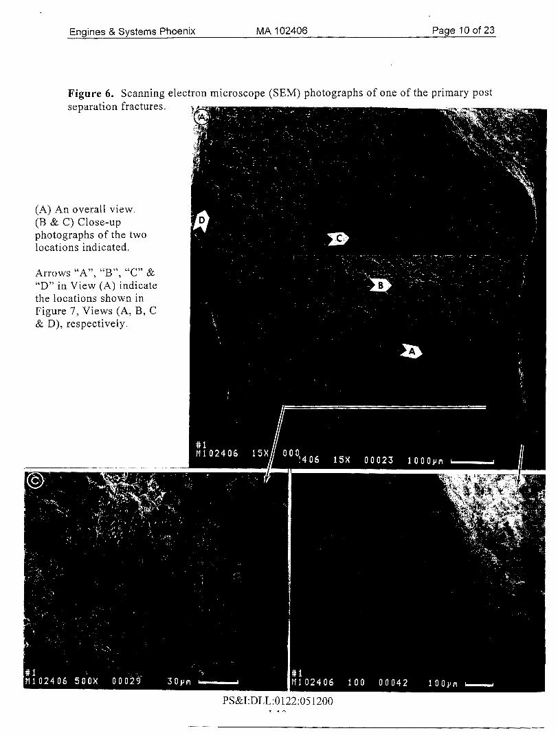
Figure 6. Scanning electron microscope (SEM) photographs of one of the primary post separation fractures .
(A) An overall view. (B & C) Close-up photographs of the two locations indicated.
Arrows “A”, “B”, “C” & “D” in View (A) indicate the locations shown in Figure 7, Views (A, B, C & D), respectively.
PS&I:DLL:0122:051200 T . A

Engines & Systems Phoenix MA I02406 Page 1 1 of 23
Figure 7. (A, B, C & D) SEM close-up photographs of the post separation locations denoted by Arrows “A”, “By’, “C” & “D” in Figure 6A, respectively.
PS&I:DLL:O 122:05 1200 1-1 1
Enaines & Svstems Phoenix MA I02406 Paqe 12 of 23
PS&I:DLL:0122:05 1200 1-12

Engines & Systems Phoenix MA 102406 Page 13 of 23
Figure 9. SEM photographs of one of the exposed fractures at pin slot “D” (reference Fiiure 5B). (4 An overall view. (B, C & D) Close-up photographs of the locations indicated by arrows “B”, “C” & “D”, respectively, in View (A).
PS&I:DLL :O 122:O 5 1200 1-13
Engines & Systems Phoenix MA I02406 Page 19 of 23
Figure 15; SEM photographs of (A & B) one of the locations on the outer diameter of the cone with heavy damage and (C & D) the score marks on the outer diameter. Magnifications: (A) - 30X, (B) - lOOX (C) - 200X & (D) - 500X.
PS&I:DLL:0122:051200 1-19
Engines & Systems Phoenix MA 102406 Page 18 of 23
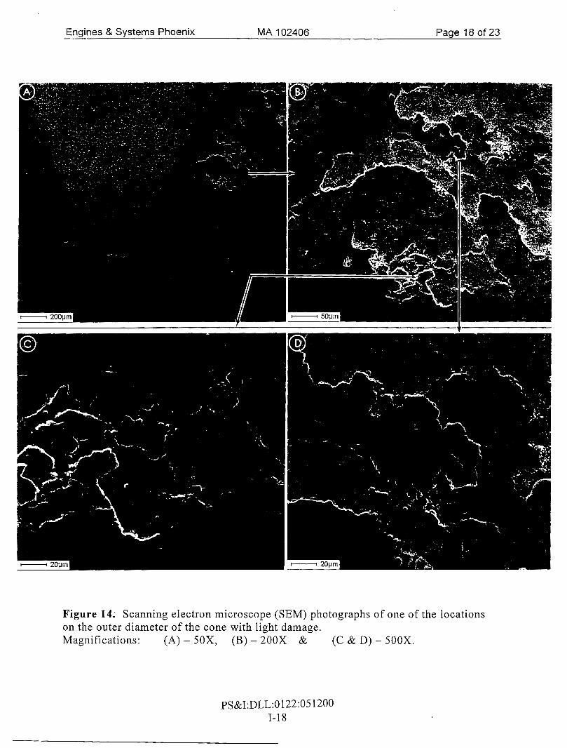
Figure 14. Scanning electron microscope (SEM) photographs of one of the locations on the outer diameter of the cone with light damage. Magnifications: (A) - 5 0 X , (B) - 200X & (C & D) - 500X.
PS&I:DLL:O 122:05 1200 1-18
Engines & Systems Phoenix MA 102406 Page 17 of 23
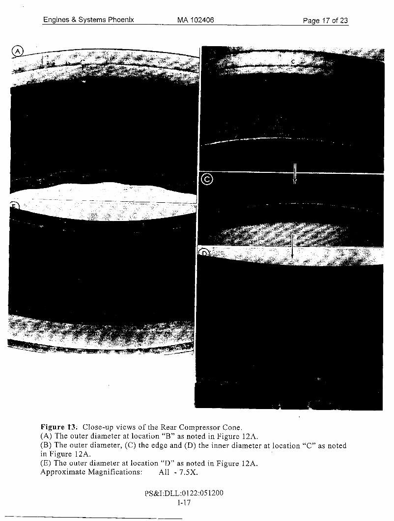
Figure 1’3; Close-up views of the Rear Compressor Cone. (A) The outer diameter at location “B” as noted in Figure 12A. (B) The outer diameter, (C) the edge and (D) the inner diameter at location “C” as noted in Figure 12A. (E) The outer diameter at location “D” as noted in Figure 12A. Approximate Magnifications: All - 7.5X.
PS&I:DLL:O 122:05 1200 1-17

MA 102406 Page 16 of 23 Engines & Systems Phoenix
Figure 12. (A) Overall view and close-up views of the Rear Compressor Cone showing: (B) the outer diameter, (C) the edge and (D) the inner diameter. Approximate Magnifications:
Letters “B”, “C”& “D” in View (A) denote the locations shown in Figure 13. The white arrow in View (B) denotes the location of the score marks on the outer diameter.
(A) - 1.3X & (B, C & D) - 7.5X.
PS&I:DLL:0122:05 1200 1-16

Engines & Sys tems Phoenix MA I02406 P a g e 15 of 23
Figure 11. (A) Optical photomicrograph of a cross section adjacent and parallel to one of the pin slots showing the fracture with (B & C) photomicrographs showing the grain sizes at the forward and aft locations, respectively, of the disk rim. Arrow “0” in View (A) denotes the fracture origin. Magnifications: (A) - 25X & (B & C) - 1OOX.
PS&I:DLL:0122:05 1200 1-15

Engines & Systems Phoenix MA 102406 Page 14 of 23
Figure 10. (A, B, C & D) Optical photomicrographs of a cross section adjacent and parallel to one of the pin slots showing successive locations along the length of the fracture. Arrow “0” in View (A) denotes the fracture origin. The white arrows in Views (A & B) denote the thick oxides at and near the fracture origin. The white arrow in View (C) denotes the oxidation associated with grain boundary cracks. Not etched. Magnification: All - 200X.
PS&I:DLL:O 122:05 1200 1-14

Enaines & Svstems Phoenix MA 102406 Paae 23 of 23
.. .... .. .
Figure 19; Optical photomicrographs of cross-sections (A & B) through the remaining tip portion of one of the longest blades and (C & D) through one of the blade tip shrouds. Electrolytically etched with 10% Oxalic. Magnifications: (A & C) - 500X & (B & D) - 1OOOX.
PS&I :DLL : 0 1 22: 05 1200 1-23

Engines & Systems Phoenix MA 102406 Page 22 of 23
PS&I:DLL:0122:051200 (E) Unidentified pieces @ I .2X.
1-22
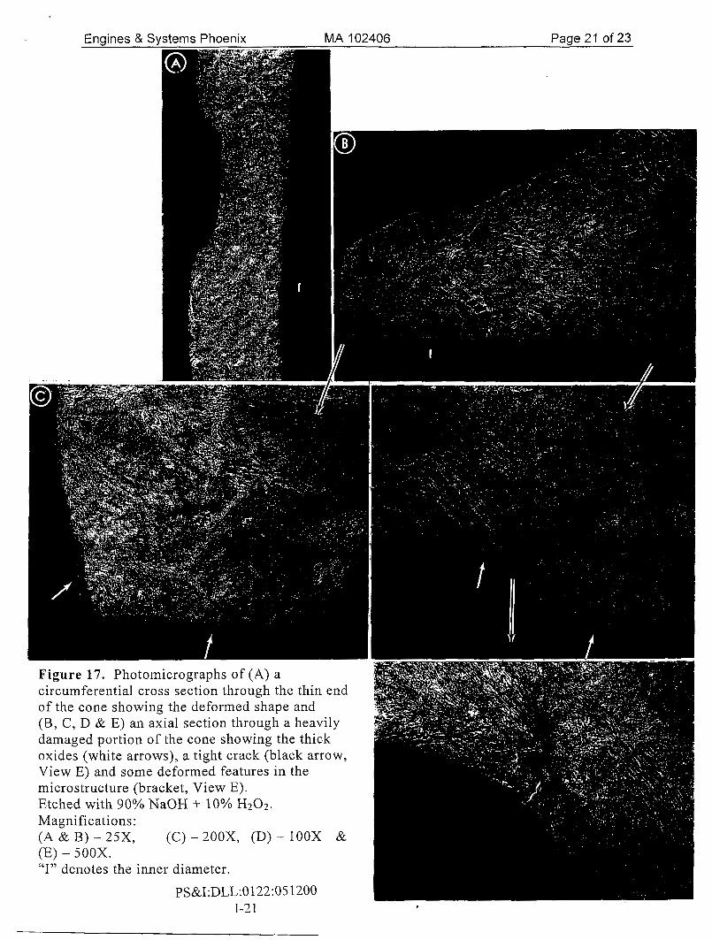
Figure 17. Photomicrographs of (A) a circumferential cross section through the thin end of the cone showing the deformed shape and (B, C, D & E) an axial section through a heavily damaged portion of the cone showing the thick oxides (white arrows), a tight crack (black arrow, View E) and some deformed features in the microstructure (bracket, View E). Etched with 90% NaOH + 10% H202.
Magnifications: (A & B) - 25X, (C) - 200X, (D) - IOOX & (E) - 500X. “I” denotes the inner diameter.
PS&I:DLL:0122:05 1200 1-2 1
Engines & Systems Phoenix MA I02406 Page 20 of 23
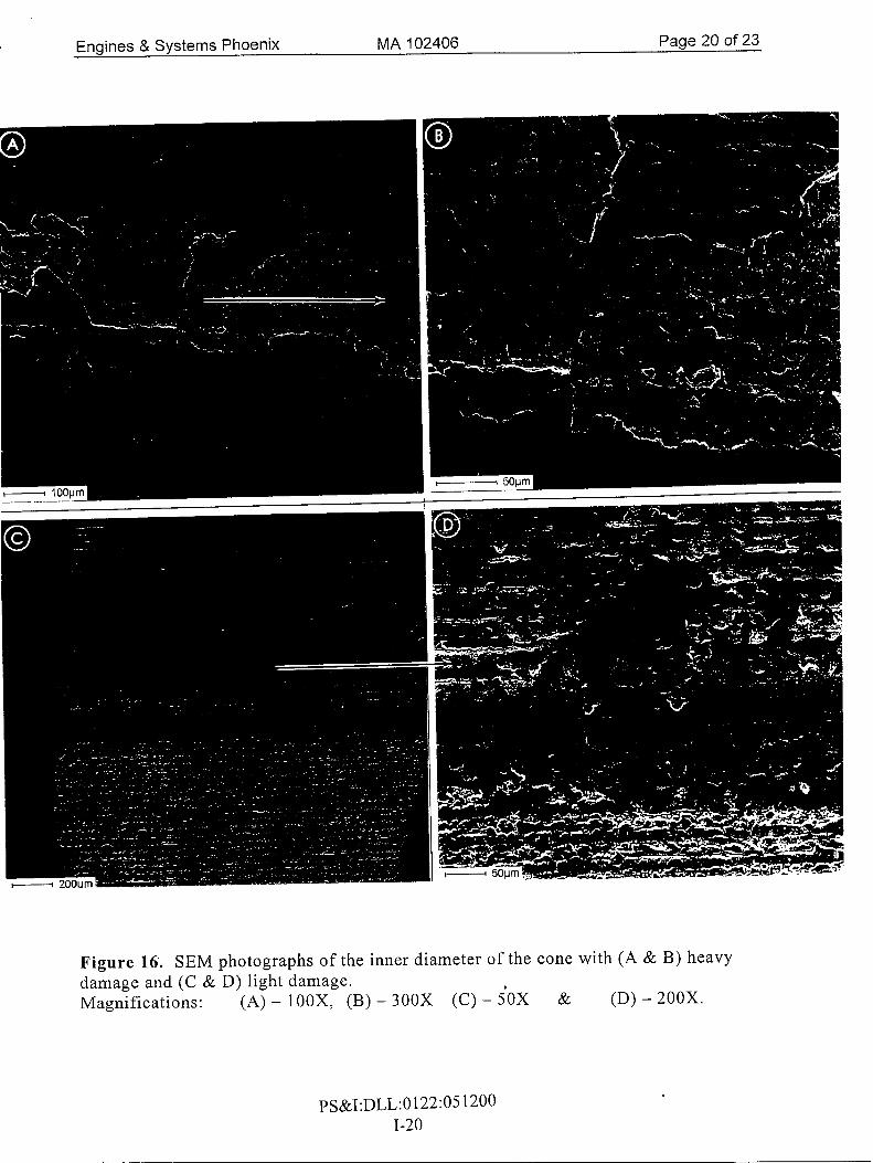
Figure 16. SEM photographs of the inner diameter of the cone with (A & B) heavy damage and (C & D) light damage. Magnifications: (A) - lOOX, (B) - 300X (C) - iOX & (D) - 200X.
PS&I:DLL:0122:05 1200 1-20
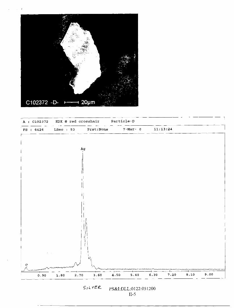
A : C102372 EDX @ red crosshair Particle-D
FS : 6426 LSec : 53 Prs t :None 7-Mar- 0 11: 13 : 24 -
\."L --- 0.90 1.80 2.70 3.60 4.50 5.40 6 I 30 7.20 8.10 9.00
SI L PS&I:DLL:O122:051200 11-5

09/08/00 10:38 'IP002 385 2429 HONEYWELL PS&I @I 003
Looper, Dave
From: Welch, Jim Sent: Thursda March 02.2000 7: 16 AM To: Looper, gave Cc: Subject: T53L138 &N LE24073
Hanenbur , Jason; Elliott. Paul; Morgan, Mike
Records at CCAD show this englne was run in test cell at CCAD on 8 april 1993-----There is no record of it having been repaired or overhauled, only tested
1