tearout isometric sketches and more
TRANSCRIPT

43Azim Premji University At Right Angles, November 2019
ClassRoom
Isometric Sketches and MoreTearOut
Isometric or triangular dot sheets are different from the square grid in two ways:
I. The square grid looks the same even if the orientation changes from landscape to portrait or vice versa (Figure 1). But the isometric grids look slightly different in each orientation. One of the orientations (Figure 2) has horizontal lines (by joining nearest grid points) while the other (Figure 3) has vertical ones. For isometric sketches of 3D solids, the latter orientation is needed.
Figure 1
Figure 2
Figure 3
II. If you pick a random point A on the square grid and identify all its immediate neighbours (at most 8 of them) then some of them (the purple ones) would be at a larger distance from A, compared to others (the blue ones) – see Figure 4. But if the same thing is repeated with a random point B on the isometric dot sheet, all the immediate neighbours (at most 6 of them) would be at the same distance from B (Figure 5). This is why it is called isometric.
Figure 4 Figure 5
Get some isometric dot sheets, a pencil, an eraser and, ideally, a scale to start. For the later part, it would help to have some interlocking cubes.
1. Cubes and cuboidsa. Make the isometric sketch of a cube
b. Make an isometric sketch of a cuboid made by joining 3 cubes. Can you make the sketch in any other way? How?
In this 4th TearOut, we will use the isometric dot sheet to visualize various solid shapes. As before, pages 1 and 2 are a worksheet for students while pages 3 and 4 give guidelines to the facilitator. Since we will be exploring solids, it is a good idea to have some interlocking cubes handy to make some of those solid shapes.
Isometric Sketches and more
In this 3rd TearOut, we will use the isometric dot sheet to visualize various solid shapes. As before, pages 1 and 2 are a worksheet for students while pages 3 and 4 give guidelines to the facilitator. Since we will be exploring solids, it is a good idea to have some interlocking cubes handy to make some of those solids.
Isometric or triangular dot sheets are different from the square grid in two ways:
I. The square grid looks the same even if the orientation changes from landscape to portrait or vice versa (Figure 1). But the isometric grids look slightly different in each orientation. One of the orientations (Figure 2) has horizontal lines (by joining nearest grid points) while the other (Figure 3) has vertical ones. For isometric sketches of 3D solids, the latter orientation is needed.
Figure 1 Figure 2 Figure 3
II. If you pick a random point A on the square grid and identify all its
immediate neighbours (at most 8 of them) then some of them (the purple ones) would be at a larger distance from A, compared to others (the blue ones) – see Figure 4. But if the same thing is repeated with a random point B on the isometric dot sheet, all the immediate neighbours (at most 6 of them) would be at the same distance from B (Figure 5). This is why it is called isometric.
Get some isometric dot sheets, a pencil, an eraser and, ideally, a scale to start. For the later part, it would help to have some interlocking cubes.
1. Cubes and cuboids a. Make the isometric sketch of a cube b. Make an isometric sketch of a cuboid made by joining 3 cubes. Can you make the sketch in any
other way? How? c. Make an isometric sketch of a cuboid with dimension 3 ×
2 × 5. Can you make this in other ways? d. Make an isometric sketch of a cuboid which has a square
face at least 4 square units big. What are the possibilities for the dimension perpendicular to the square face?
e. Make an isometric sketch of any cuboid of your choice.
2. Letters a. Make isometric sketches of the following letters:
E, F, H, I, L, T Can these be done in any other way? How?
Figure 4
A
Figure 5
B
Figure 6

44 Azim Premji University At Right Angles, November 2019
c. Make an isometric sketch of a cuboid with dimension 3 × 2 × 5. Can you make this in other ways?
d. Make an isometric sketch of a cuboid which has a square face at least 4 square units big. What are the possibilities for the dimension perpendicular to the square face?
e. Make an isometric sketch of any cuboid of your choice.
2. Lettersa. Make isometric sketches of the following letters:
E, F, H, I, L, T
Can these be done in any other way? How? [See examples in Figure 6 for T]
b. Make isometric sketches of the following letters: A, K, M, N, V, W, X, Y, Z
How are these different from the above?
c. Make isometric sketches of the remaining letters of the alphabet. How are those different from the 2nd set?
Figure 6
3. 3D ambigrams a. Pick any 3 letters from 2a and make a 3D
ambigram. Make an isometric sketch of it illustrating the 3 letters as projections. Interlocking cubes would be very helpful for this. Multiple dice can be taped together as an alternative. [See example in Figure 7 for H, T and L]
b. Repeat with a new set of 3 letters, at least one from each set 2a and 2b.
In this case, interlocking cubes won’t help beyond a point. So, use your imagination and intuition.
c. Repeat with a new set of 3 letters, one from each set 2a, 2b and 2c.
Figure 7
4. Escher Escher is famous for his drawings that defy common sense, like the triangular bar (Figure 8).
Make your own Escher type drawing.
Figure 8
45Azim Premji University At Right Angles, November 2019
This is a ‘Low Floor High Ceiling’ worksheet that starts simply and within the upper primary syllabus but stretches into imagination that is abstract because it is unreal! The main focus is on developing spatial sense and visualising solid shapes. These ideas are typically ignored in mainstream teaching, because they entered the syllabus and textbooks relatively recently and therefore teachers lack exposure to them and experience in dealing with these concepts. At the same time, visualising 3D space and solids and the ability to map them to 2D are important skills for designing – a must-have for engineering and architecture, to say the least.
The initial questions are suitable for upper primary students. Interlocking cubes will be very useful for one question. It is certainly possible to tackle the question without manipulatives. But that would require a well-developed spatial sense, which may be rare. The last question demands higher order thinking in drawing something that breaks the rule and at the same time allows for artistic freedom.
1. This is a simple question dealing with isometric sketches of cubes and cuboids. The key thing is to realize that three adjacent faces of a cuboid are shown, and each rectangular face becomes a parallelogram (and squares become rhombi). It allows the exploration that a square-faced cuboid can be tall (i.e., the unequal dimension being longer than the equal ones) or short (with a shorter 3rd dimension).
This skill can be used to draw large cubes (and cuboids) and check the associative property of multiplication with fractions, which was discussed in a poster in the Nov 2018 issue. Figure 9 illustrates the product 4/3 × 5/6 × 1/2 – the unit cube has been stretched to get 4/3, 5/6 of that is shaded by “” and 1/2 of the cuboid is shaded by “∘”.
Figure 9
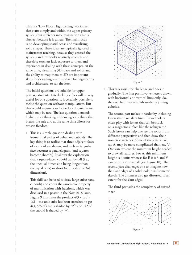
2. This task raises the challenge and does it gradually. The first part involves letters drawn with horizontal and vertical lines only. So, the sketches involve solids made by joining cuboids.
The second part makes it harder by including letters that have slant lines. Pre-schoolers often play with letters that can be stuck on a magnetic surface like the refrigerator. Such letters can help one see the solids from different perspectives and then draw their isometric sketches. Some of the letters like, say A, may be more complicated than, say V. One can explore the minimum height needed to draw all features. For A, this minimum height is 4 units whereas for E it is 5 and V can be only 2 units tall (see Figure 10). The second part challenges one to imagine how the slant edges of a solid look in its isometric sketch. The distances also get distorted to an extent for the slant edges.
The third part adds the complexity of curved edges.
Figure 10

46 Azim Premji University At Right Angles, November 2019
3. This is where it gets quite challenging. Therefore, we strongly recommend trying this question with interlocking cubes. There are two challenges: (i) creating an ambigram that will cast predetermined shadows and (ii) isometric sketch of the solid. Now, (i) requires understanding of top-view, front-view and side-view of a solid because these views are chosen, and one must reverse engineer the solid concerned. It will be an interesting exploration to see if there can be two different ambigrams (excluding rotation) for the same set of three letters. Sometimes there are more than one possibility. For (ii), it is important to select the angle that will generate the best isometric sketch. Figure 7 illustrates an ambigram for L, T and H where the shadow of L is shown, and T and H are marked with “×” and “///” respectively.
This also starts with only perpendicular edges where interlocking cubes can be used to create the ambigram and then draw its sketches from different angles. This reverse engineering itself can be challenging and therefore engaging.
Then, the slant edges get added and then interlocking cubes won’t be of help. So, at the second level, one has to use the spatial sense developed so far to imagine the solid that can cast the predetermined shadows.
The last part involves curved edges. Some of the letters in 2c may actually pose less challenge since they can be achieved by just rounding some corners.
We have suggested three levels – I. all letters from 2a, II. At least one from 2a and 2b each and III. One from each of 2a, 2b and 2c. There are seven more possibilities, e.g. all three from 2b, etc. We encourage exploring them for the adventure-seeking readers. The cover of a famous book Gödel, Escher, Bach: an Eternal Golden Braid (or GEB) sports two ambigrams for the initials G, E and B. We hope that this exercise will pave the way for such imaginations.
4. This question can be the most fun! When mapping the 3D space on 2D, we have to abide by some rules. However, in this task, those very rules have to be broken – in a subtle way – to create something that is impossible in the physical world. Classic examples include the Penrose triangle (Figure 8) and the Penrose stairs (Figure 11) based on that.
This TearOut is based on explorations by the following MA Education students at Azim Premji University: Ankita Sharma, Keshvi and Ram Saroj, who got addicted to the isometric dot sheets!
Figure 11