tech 104 – technical graphics communication week 13: 3d modeling basics
TRANSCRIPT
TECH 104 – Technical Graphics Communication
Week 13:
3D Modeling Basics

TECH 104 – Technical Graphics Communication
The 3D model is…….
1. The visible representation of the database
2. Holds all its data within the structure of the model
3. Can be edited using Boolean Logic and other commands to add chamfers and fillets, etc.
4. Constructed from 2D geometry and other 3D models
Week 12: 3D Modeling Basics
TECH 104 – Technical Graphics Communication
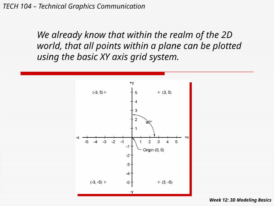
We already know that within the realm of the 2D world, that all points within a plane can be plotted using the basic XY axis grid system.
Week 12: 3D Modeling Basics

TECH 104 – Technical Graphics Communication
Within the 3D coordinate system, a third axis (Z) is added to allow for the construction of volumetric solid and surface models.
Week 12: 3D Modeling Basics

TECH 104 – Technical Graphics Communication
As we have already seen, a 2D rectangle can be extruded (pulled) into a 3D prism.
Here we can also see the address of each vertex displayed with their X,Y,Z values.
Week 12: 3D Modeling Basics

TECH 104 – Technical Graphics Communication
The UCS icon shown at the bottom of the drawing interface here appears in its 2D format. In this environment, we can construct the foundational 2D components of a 3D model.
Week 12: 3D Modeling Basics

TECH 104 – Technical Graphics Communication
For 3D models, we must use an environment that allows for a volumetric model to be constructed. The “Right Hand Rule” allows us to understand the use of 3-axes.
Axis names are given to the first 2 fingers and the thumb.
Week 12: 3D Modeling Basics

TECH 104 – Technical Graphics Communication
Points in space can be located using a variety of methods. Here polar coordinates are entered to identify the basic shape that will be extruded into a cylinder along the Z axis.
Week 12: 3D Modeling Basics

TECH 104 – Technical Graphics Communication
REMEMBER: When constructing the 2D foundational components of a 3D model, geometry may be created using both absolute and relative commands.
Absolute values Relative values Week 12: 3D Modeling Basics

TECH 104 – Technical Graphics Communication
As we will see, should we wish to add supplemental coordinate systems, we can attach additional local coordinate axes to any part of a 3D model.
Week 12: 3D Modeling Basics

TECH 104 – Technical Graphics Communication
Wireframe models, or features within a 3D model, may appear ambiguous due to our visual orientation.
Week 12: 3D Modeling Basics
TECH 104 – Technical Graphics Communication
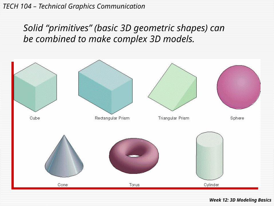
Solid “primitives” (basic 3D geometric shapes) can be combined to make complex 3D models.
Week 12: 3D Modeling Basics
TECH 104 – Technical Graphics Communication
Simple primitive shapes, can easily be put together using Boolean logic to create complex solid models.
Let’s look at an example……
Week 12: 3D Modeling Basics

TECH 104 – Technical Graphics Communication
Here, we can see that cylinders and cones have been added to prisms to create the basic box shape of the camera.
A wedge is then added to the top to form the view finder.
A cylinder is added to form the film case, and a subtraction was used to provided the angular shape needed.
Week 12: 3D Modeling Basics

TECH 104 – Technical Graphics Communication
Primitive data can be unioned (added) subtracted, or intersected (shared) with other primitives.
NOTE:
SUBTRACTION is also known in modeling as DIFFERENCE.
Week 12: 3D Modeling Basics

TECH 104 – Technical Graphics Communication
Using the UNION command, we are able to join the 2 parents into a new model.
This new model may be thought of as the “child” of the parent models.
As the child, the model will display some of the characteristics of each parent.
Week 12: 3D Modeling Basics
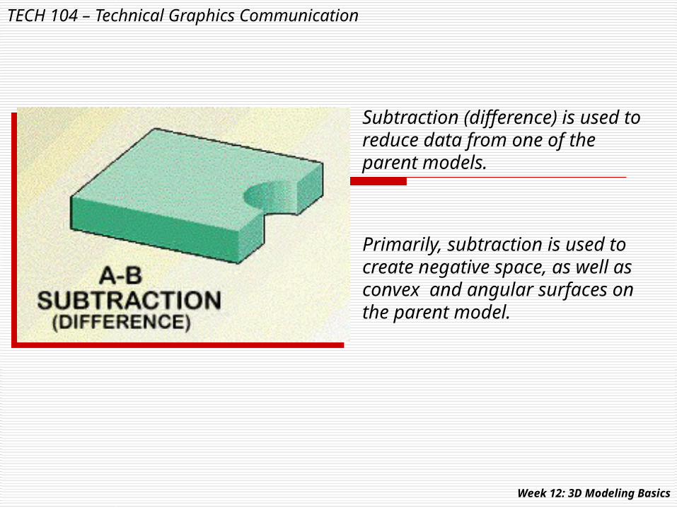
Subtraction (difference) is used to reduce data from one of the parent models.
Primarily, subtraction is used to create negative space, as well as convex and angular surfaces on the parent model.
TECH 104 – Technical Graphics Communication
Week 12: 3D Modeling Basics
TECH 104 – Technical Graphics Communication
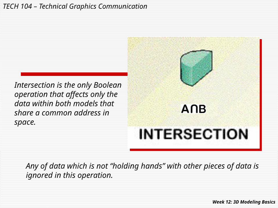
Intersection is the only Boolean operation that affects only the data within both models that share a common address in space.
Any of data which is not “holding hands” with other pieces of data is ignored in this operation.
Week 12: 3D Modeling Basics
TECH 104 – Technical Graphics Communication
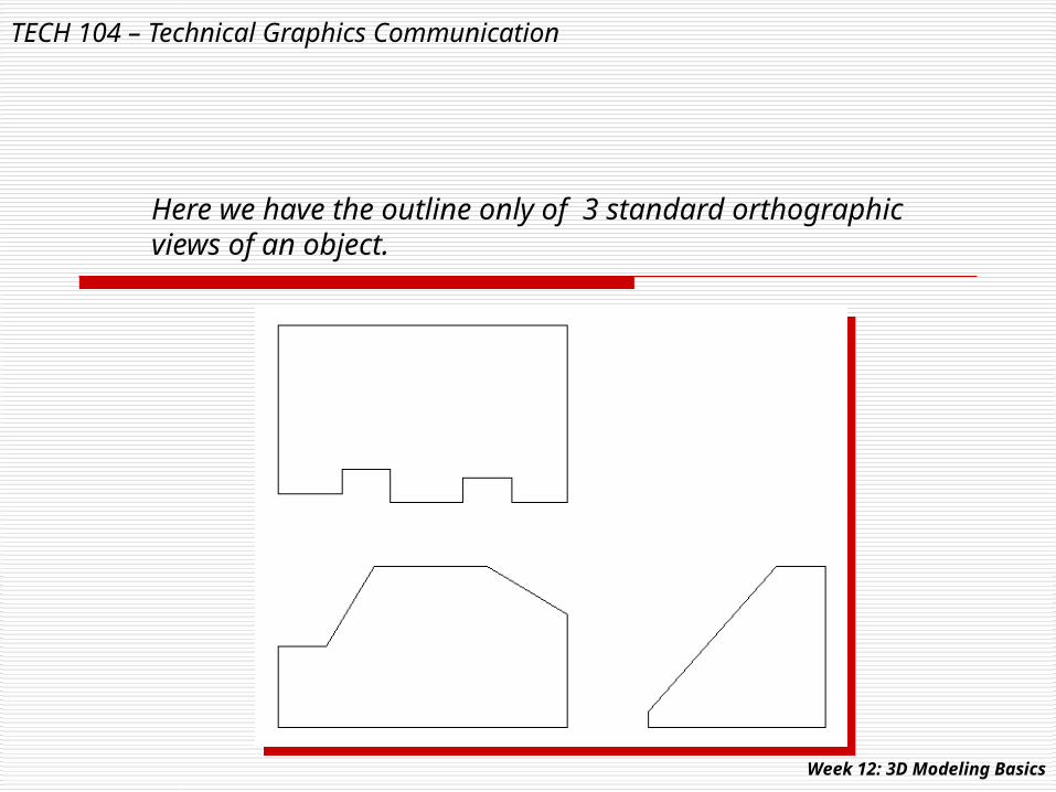
Here we have the outline only of 3 standard orthographic views of an object.
Week 12: 3D Modeling Basics

TECH 104 – Technical Graphics Communication
The profiles are then arranged in 3D space to show their true alignment with the X, Y & Z axes.
Week 12: 3D Modeling Basics

TECH 104 – Technical Graphics Communication
Each of the profiles is extruded a distance great enough to pass through each solid component.
When using intersection, each component’s length is unimportant as long as they each extend past the other components.
Remember: Only data that shares common space will be used to create the model.
Week 12: 3D Modeling Basics
TECH 104 – Technical Graphics Communication
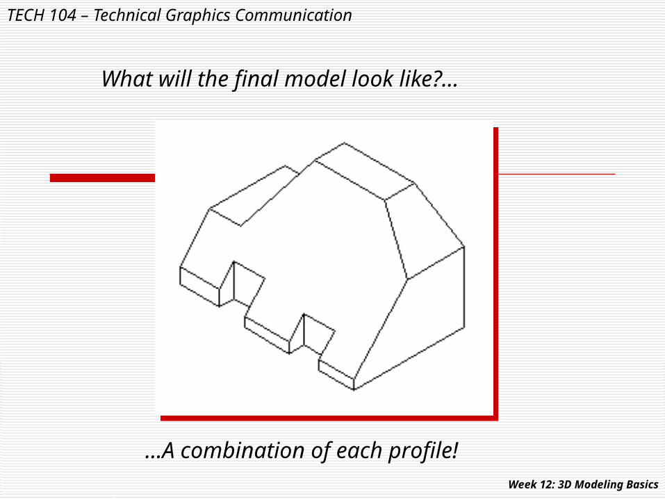
What will the final model look like?…
…A combination of each profile!Week 12: 3D Modeling Basics

TECH 104 – Technical Graphics Communication
Consider these two profiles of a solid model…
What will the final model look like?
Week 12: 3D Modeling Basics

TECH 104 – Technical Graphics Communication
Step 1: Align the profiles
Step 2: Extrude the profiles and subtract the cylinders
Step 3:Intersect theparent models
Week 12: 3D Modeling Basics
TECH 104 – Technical Graphics Communication
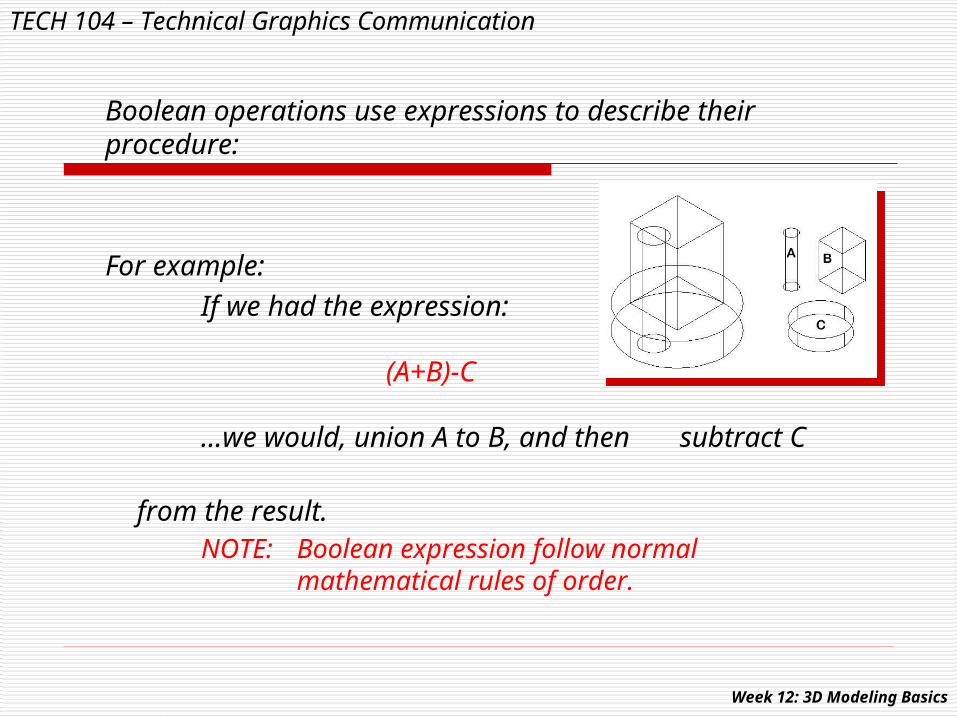
Boolean operations use expressions to describe their procedure:
For example:If we had the expression:
(A+B)-C
…we would, union A to B, and then subtract C
from the result.NOTE: Boolean expression follow normal
mathematical rules of order.
Week 12: 3D Modeling Basics

TECH 104 – Technical Graphics Communication
Therefore, (A+B)-C, would result in…..
Week 12: 3D Modeling Basics

TECH 104 – Technical Graphics Communication
2D geometry of any shape can also be used to generate a 3D solid model. This is done through a variety of sweeping operations.
Here are some examples…..
Week 12: 3D Modeling Basics

TECH 104 – Technical Graphics Communication
Linear sweeps are also known as “extrusions”:
Extrusions may be parallel to the Z axis, or move in the Z direction at an angle.
NOTE: in 3D space the names of the axes change:
Z becomes W….X becomes U….Y becomes V
Week 12: 3D Modeling Basics

TECH 104 – Technical Graphics Communication
Revolving a “profile” (2D shape) around an identified axis is an example of radial sweeping.
Here, we can see that the profile may be revolved in a full 360 degrees, or in a specified number of degrees less than 360.
Week 12: 3D Modeling Basics

TECH 104 – Technical Graphics Communication
Sweeps may also follow a specified path. When the path enters space above the XY construction plane, the geometry used to create the path becomes known as a “space curve”.
Extrusions that are parallel to the Z(X) axis, may also be “tweaked” as shown in Example (B).
Tweaking allows a circle that would normally become a cylinder, to be extruded as a cone shape.
Week 12: 3D Modeling Basics

TECH 104 – Technical Graphics Communication
Here, we have an example of a solid model created by sweeping and Boolean operations.
Week 12: 3D Modeling Basics
TECH 104 – Technical Graphics Communication
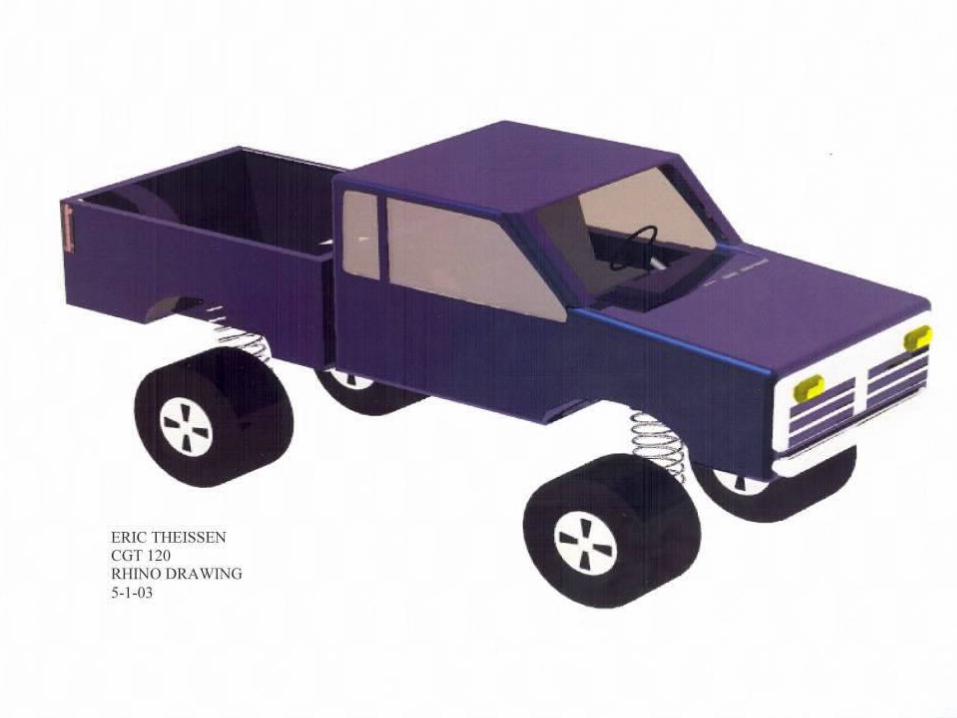
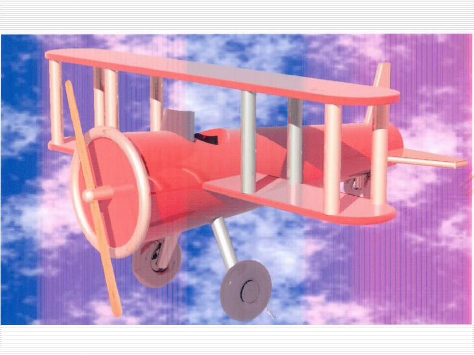
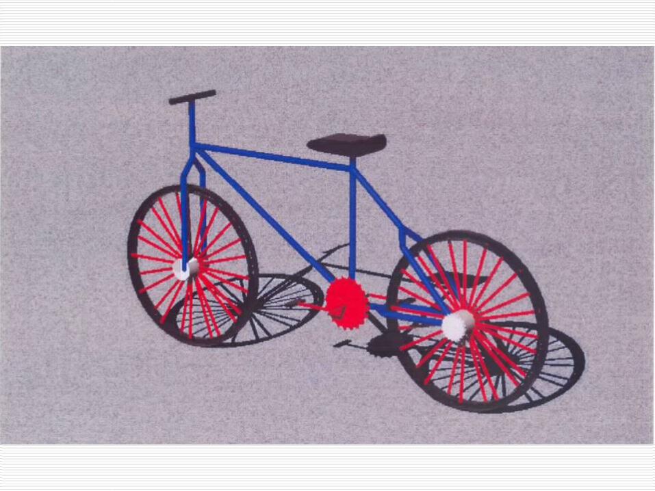
Vehicle Examples
Week 12: 3D Modeling Basics


TECH 104 – Technical Graphics Communication
Week 14:
Solid Modeling…continued!
Week 12: 3D Modeling Basics