technical a guide for upgrading information centum...
TRANSCRIPT
TechnicalInformation
A Guide for UpgradingCENTUM V and CENTUM-XLto CENTUM VP (for Vnet/IP)
TI 33K01B10-50E
TI 33K01B10-50E©Copyright Mar. 2015 (YK)1st Edition Mar. 2015 (YK)
Yokogawa Electric Corporation2-9-32, Nakacho, Musashino-shi, Tokyo, 180-8750 JapanTel.: 81-422-52-5634 Fax.: 81-422-52-9802

Blank Page
i
TI 33K01B10-50E
PrefaceThis document describes how to upgrade an existing CENTUM V or CENTUM-XL system to the latest CENTUM VP (Vnet/IP).
Trademarks• CENTUMisaregisteredtrademarkofYokogawaElectricCorporation.
• Allothercompanyandproductnamesmentionedinthisdocumentaretrademarksorregis-tered trademarks of their respective companies.
• YokogawadoesnotuseTMor®markstoindicatethosetrademarksorregisteredtrade-marks in this document.
Abbreviated TermsThe abbreviations and acronyms of Yokogawa products that are mentioned in this document are listed in Glossary.
All Rights Reserved Copyright © 2015, Yokogawa Electric Corporation Mar. 27, 2015-00

Blank Page

Toc-1
TI 33K01B10-50E
A Guide for UpdatingCENTUM V and CENTUM-XLto CENTUM VP (for Vnet/IP)
Mar. 27, 2015-00
CONTENTS1. The Need for Upgrade .............................................................................. 1-1
1.1 System Deterioration Due to Aging ................................................................1-21.2 Following to the Change ..................................................................................1-31.3 Increasing System Maintenance Cost ............................................................1-3
2. Style of Upgrade ....................................................................................... 2-12.1 Batch-upgrade to Vnet/IP, FIO .........................................................................2-1
3. Scope of Upgrade ..................................................................................... 3-13.1 Applicable Existing System .............................................................................3-13.2 Non-applicable Existing System .....................................................................3-3
4. Procedure and Details of Upgrade ......................................................... 4-14.1 Upgrade Procedure ..........................................................................................4-14.2 Details of Pre-assessment ...............................................................................4-24.3 Remedial Treatment ..........................................................................................4-44.4 HardwareModificationandAddition ..............................................................4-5
4.4.1 Modifying FCS ...................................................................................4-5
4.4.2 On-siteModification ...........................................................................4-8
4.4.3 Upgrading the Existing I/O Card Unit ................................................. 4-9
4.4.4 InstallationSpecifications ................................................................ 4-11
4.5 Application Software Conversion ................................................................4-124.5.1 Conversion Procedure .....................................................................4-12
4.5.2 Work by Upgrading Tool ...................................................................4-12
4.5.3 Handling Tuning Parameters ...........................................................4-13
4.5.4 Functional Difference in the Data Item and Block Mode .................4-14
4.6 On-site System Operations Check ...............................................................4-184.7 Maintenance After Upgrade ...........................................................................4-18
TI 33K01B10-50E 1st Edition

Toc-2
TI 33K01B10-50E
5. System Functions After Upgrade ........................................................... 5-15.1 System Overview ..............................................................................................5-1
5.1.1 Overall Control Functions ..................................................................5-1
5.1.2 Comparison of Function Blocks’ Common Function ......................... 5-3
5.1.3 Comparison of Continuous Control Function .................................... 5-4
5.1.4 Comparison of Sequence Control Function ...................................... 5-8
5.1.5 Comparison of Computational Function ..........................................5-16
5.1.6 Comparison of Optional Control Function .......................................5-18
5.2 UpgradeSpecifications ..................................................................................5-195.3 Application Capacity of Upgraded FCS........................................................5-21
Appendix 1. Signal Conditioner Models ...............................................App.1-1Appendix 2. Installation Conditions for CENTUM V and CENTUM-XL ....App.2-1Appendix 3. Tuning Parameter Differences ..........................................App.3-1Appendix 4. Functions Related to Upgrade ..........................................App.4-1Appendix 5. Glossary ..............................................................................App.5-1
Mar. 27, 2015-00
1. The Need for Upgrade 1-1
TI 33K01B10-50E
1. The Need for UpgradeMany CENTUM V and CENTUM-XL systems – Yokogawa DCSes – have been sold worldwide since 1983 and 1988, respectively, and quite a few of these systems have been in operation for more than ten years. However, along with the years that have passed since the systems were introduced,theefficiencyofplantoperationisdecreasingforthefollowingreasons:• Systemfailureoccursmoreoftenduetoaging.
• Functionsbecomeobsolete.
• Systemmaintenancecostincreases.
Accordingly, there is increasing demand among customers for a low-cost system upgrade method that can improve company competitiveness.
Mar. 27, 2015-00
1. The Need for Upgrade 1-2
TI 33K01B10-50E
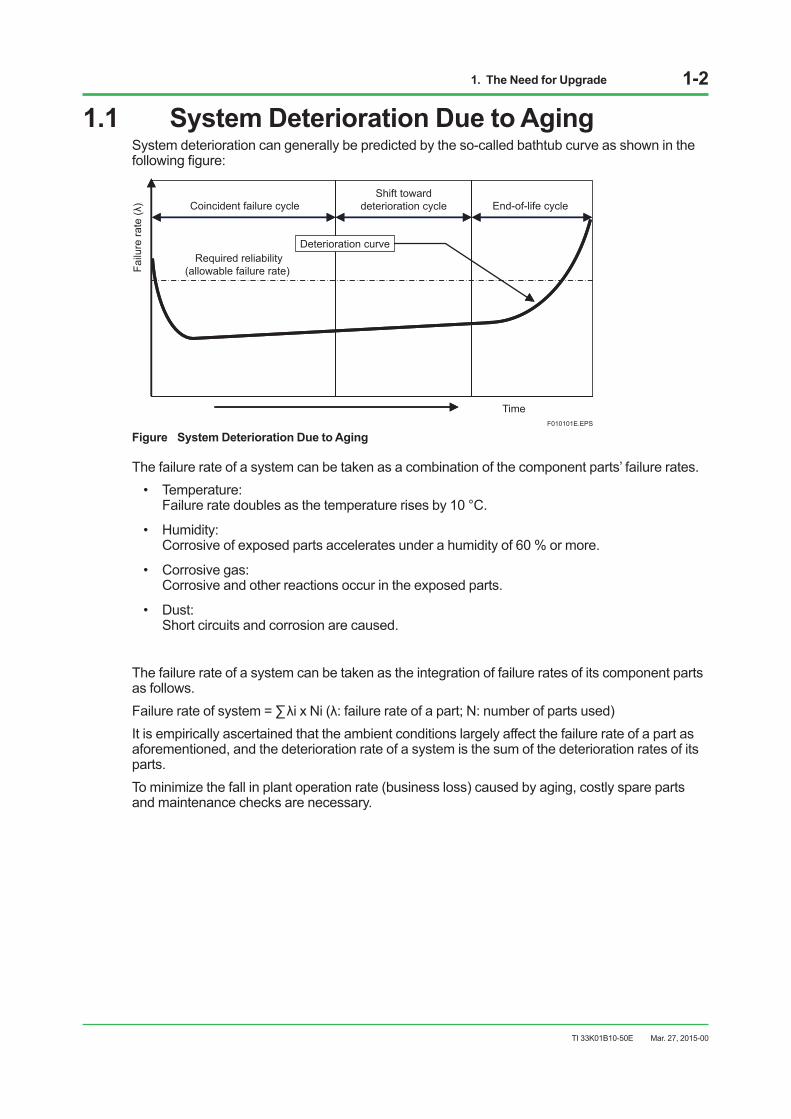
1.1 System Deterioration Due to AgingSystem deterioration can generally be predicted by the so-called bathtub curve as shown in the followingfigure:
Coincident failure cycle
Required reliability (allowable failure rate)
Shift toward deterioration cycle
Time
End-of-life cycle
F010101E.EPS
Failu
re ra
te (λ
)
Deterioration curve
Figure System Deterioration Due to Aging
The failure rate of a system can be taken as a combination of the component parts’ failure rates.• Temperature:
Failure rate doubles as the temperature rises by 10 °C.
• Humidity: Corrosive of exposed parts accelerates under a humidity of 60 % or more.
• Corrosivegas: Corrosive and other reactions occur in the exposed parts.
• Dust: Short circuits and corrosion are caused.
The failure rate of a system can be taken as the integration of failure rates of its component parts as follows.Failurerateofsystem=∑λixNi(λ:failurerateofapart;N:numberofpartsused)It is empirically ascertained that the ambient conditions largely affect the failure rate of a part as aforementioned, and the deterioration rate of a system is the sum of the deterioration rates of its parts.To minimize the fall in plant operation rate (business loss) caused by aging, costly spare parts and maintenance checks are necessary.
Mar. 27, 2015-00
1. The Need for Upgrade 1-3
TI 33K01B10-50E
1.2 Following to the ChangeIt is often the case that technology not established at the introduction of an existing system comesintopracticelateranditsapplicationtoplantcontrolsignificantlyimprovesplantefficiency.To remain competitive in a boarder-less global market, it is necessary for businesses to follow the innovation speed of computer technology, because technology becomes obsolete as soon as it is introduced. Production sites are required to be hot-linked with the corporate decision-making systems to facilitate the swift incorporation of market changes into production. This necessitates production systems to be linked with the plant information management system (PIMS) and corporate decision-making systems such as the enterprise resource planning (ERP) and manufacturing executionsystem(MES),andthelinkstobesoflexibleandagiletoallowunparalleledswiftresponses to market changes. In addition, to increase the competitiveness of each user’s enterprise there is demand for production systems to implement advanced control to improve efficiencyofsteady-stateoperations,advancedoperationsupportfunctionstoimproveefficiencyofnon-steady-stateoperations,andplantresourcemanagement(PRM)toimproveefficiencyoffacility management.
1.3 Increasing System Maintenance CostRecently, the technologies for DCSs’ basic parts such as CPUs, ICs, and hard disk drives are innovating at incredibly fast speeds. Parts manufacturers consequently discontinue old products quicker than ever while catching up with the technology innovations, reviewing the sales strategies and parts productions, and putting their energies into manufacturing their workhorses.
TIPDividing the parts into groups corresponding to the individual DCS components using them and analyzing suppliers discontinuation trends, revealed that the revision-and-discontinuation cycles and supply periods are shortforthepartsusedinhumaninterfacessuchasharddiskdrives,floppydiskdrives,andCPUs.Incontrast,parts used in I/O show longer revision-and-discontinuation cycles and supply periods.
To achieve long-term steady operation of its DCSs, regardless of the ever-shortened supplying periods of basic parts, Yokogawa maintains supply of spare parts by implementing various measures including redesign with substitute parts and long-term stocks. Despite these efforts, price revisions for spare parts are becoming inevitable because the costs of long-term spare partssupplytendtoincreasesignificantlyduetotheoverwhelmingamountofdiscontinuationsbyparts suppliers.The maintenance cost for a system demonstrates a propensity to escalate because of increases in parts failure rates due to deterioration over time and in prices of spare parts.
Mar. 27, 2015-00

2. Style of Upgrade 2-1
TI 33K01B10-50E
2. Style of UpgradeIn principle, the method of upgrading is by batch-upgrade from the currently installed CENTUM V and CENTUM-XL systems to the latest CENTUM VP (Vnet/IP, FIO).To upgrade the FCS of CENTUM-XL, use the Cabinet Utility Kit (ACUKT2). To upgrade from CENTUM V, please contact the Yokogawa operation desk.
2.1 Batch-upgrade to Vnet/IP, FIOFor HMI, upgrade the existing operator station (COPSV or EOPS, etc.) to the human interface station (HIS) of CENTUM VP. In this HIS, use VI702 as the interface card for connecting to Vnet/IP.For the control station, upgrade the existing CFCS2 or EFCS, etc. to FFCS-V (*1). Replace theconventionalstationcontrolnest(SCN)withanewfieldcontrolunit(FCU),replacetheI/O nestwith a node unit, and replace the SIO-system I/O card with a FIO-system I/O card, respectively.ThecurrentlyinstalledSCcardsandfieldwiringcanbeusedasis.*1: FFCS-V is an FCS for V-net/IP and FIO of CENTUM VP. At the time of upgrade, use AFV30 as an FCU.
Thefollowingfigureshowsanexampleofbatch-upgradeofCENTUM-XLtoCENTUMVP(Vnet/IP,FIO).
HF bus
FCU
NodeUnit
FIO
SCN
I/ONest
SIO
L2SW
FFCS-VEFCD
Vnet/IP
F020101E.ai
EOPS EOPS ENGS HIS HIS ENG
Figure An example of batch-upgrade from CENTUM-XL to CENTUM VP (Vnet/IP, FIO)
Mar. 27, 2015-00
3. Scope of Upgrade 3-1
TI 33K01B10-50E
3. Scope of Upgrade
3.1 Applicable Existing System
Hardware
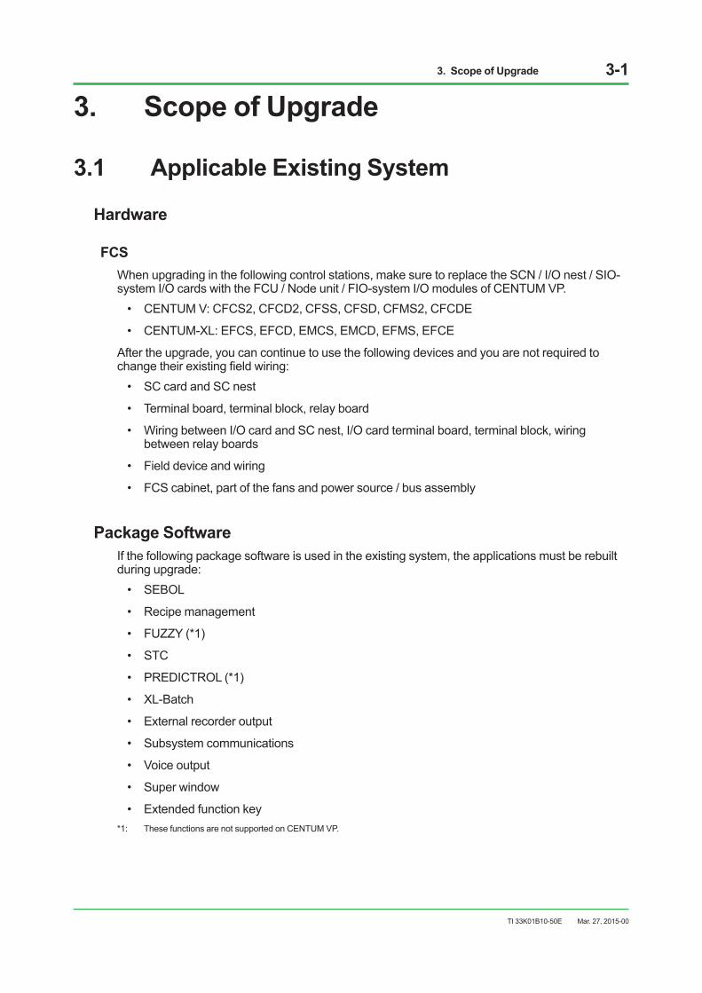
FCSWhen upgrading in the following control stations, make sure to replace the SCN / I/O nest / SIO-system I/O cards with the FCU / Node unit / FIO-system I/O modules of CENTUM VP.• CENTUMV:CFCS2,CFCD2,CFSS,CFSD,CFMS2,CFCDE
• CENTUM-XL:EFCS,EFCD,EMCS,EMCD,EFMS,EFCE
After the upgrade, you can continue to use the following devices and you are not required to changetheirexistingfieldwiring:• SCcardandSCnest
• Terminalboard,terminalblock,relayboard
• WiringbetweenI/OcardandSCnest,I/Ocardterminalboard,terminalblock,wiringbetween relay boards
• Fielddeviceandwiring
• FCScabinet,partofthefansandpowersource/busassembly
Package SoftwareIf the following package software is used in the existing system, the applications must be rebuilt during upgrade:• SEBOL
• Recipemanagement
• FUZZY(*1)
• STC
• PREDICTROL(*1)
• XL-Batch
• Externalrecorderoutput
• Subsystemcommunications
• Voiceoutput
• Superwindow
• Extendedfunctionkey*1: These functions are not supported on CENTUM VP.
Mar. 27, 2015-00

3. Scope of Upgrade 3-2
TI 33K01B10-50E
Application SoftwareYokogawa offers an application software conversion.
SEE ALSO Refer to Section 4.5 “Application Software Conversion” for details.
Custom SoftwareThere are three ways to upgrade custom software:• Usepackagesoftware–forsubsystemcommunication,reportgeneration,andthelike,use
the standardized software packages to achieve the same functions.
• Usethird-partyapplications–forITVWebcamerasandothermultimedia-relatedfunctions,use Windows system’s multimedia functions and the respective third-party applications.
• Reconfigurethefunctions–forcustomfunctionsthatcannotbesubstitutedbystandardizedsoftwarepackagesandthird-partyapplications,reconfigurationisrequired.
Mar. 27, 2015-00

3. Scope of Upgrade 3-3
TI 33K01B10-50E
3.2 Non-applicable Existing SystemThe following equipment can not be upgraded. Their recommended substitute products are shown in the table.
Component
Table Recommended Substitute ProductsEquipment out of scope of upgrade Recommended substitute Remarks
CFGW, EFGW (*1)
FFCS-V + ALR111/121communication module
Subsystem communication package (for serial communication, e.g., RS-232C, RS-485)
FFCS-V + ALE111communication module Subsystem communication package (for Ethernet)
CGWU,ECGWZ,ECGW2, ECGW3 ACG, general purpose PC Communications software should be restructured
with Exaopc.EFUS, EFUD FFCS, FFCD CFBS2 FFCS, FFCD EMCS, EMCD FFCS, FFCD, APCS
CCMS, ECMP General-purpose PC Application software should be restructured with Exaquantum, Exaopc packages, etc.
XLAIS General-purpose PC Exapilot package YEWLINK Optical repeater
*1: If CFGW or EFGW is used in the existing system, FIO’s communication modules (ALR111/ALR121 and ALE111 cards) should be addedtothefieldcontrolstation(FCS).Applicationsoftwareshouldalsoberegenerated.
I/O Card
Table Recommended substitute deviceEquipment of scope of upgrade Recommended substitute device Remarks
RS4 ALR111 Use new cables that support different shape connectors. (*2)
*1: If the CFGW and EFGW are already incorporated in the existing system, FIO’s communication modules (ALR111/ALR121 and ALE111cards)shouldbeincludedinthefieldcontrolstation(FCS).Applicationsoftwareshouldalsoberegenerated.
*2: For details, see GS 33M50J10-40E for Cables.
Mar. 27, 2015-00

4. Procedure and Details of Upgrade 4-1
TI 33K01B10-50E
4. Procedure and Details of Upgrade
4.1 Upgrade Procedure
Yes
No
Hardware modification and expansion (on site)
Operation check by on-site systems
Maintenance after upgrade
• Add Vnet/IP (L2SW) and HIS• Replace SCN of existing FCS with CENTUM VP FCU• Replace I/O nest of existing FCS with CENTUM VP node unit for FIO • On-site check after upgrade (e.g., Operation check between I/O card and FCU)
Items requiring separate estimate:• Environment improvement work• Circuit board cleaning and coating• Replacement of deteriorated parts• Check (disassemble and clean)
• Convert engineering data• Respond to different functions• Respond to new jobs as well as to additional jobs and modifications (*1)• Debug testing under test environments
• Re-adjust tuning parameters • Check operation timing
• Convert and upgrade tuning parameters
F040101E.ai
Information required for pre-assessment:• System configuration Items to investigate and report on: • Check items mounted in existing FCS• Examine system history records• Check installation environment• Evaluate deterioration at site• Propose life-prolonging measures and remedial treatment based on the investigation results
Estimation and budgeting
Pre-assessment
Quotation and budgeting for hardware modification/expansion and software upgrade
Is remedial treatment required?
Information required to create estimate:• System configuration• If nonstandard hardware required, and details• Capacity of each application - Number of internal instruments - Number of sequence tables - Number of inter-station communication instruments• If any operation tags (for CENTUM V)• If Tokuchu software required, and details• If annual maintenance agreement required, and details
Operation check on target
Upgrade of application software
*1 If new jobs as well as additional jobs and modifications are needed when upgrade is conducted.
Provide remedial treatment
Figure Upgrade Procedure
Mar. 27, 2015-00
4. Procedure and Details of Upgrade 4-2
TI 33K01B10-50E
4.2 Details of Pre-assessmentA pre-assessment is required before upgrade.
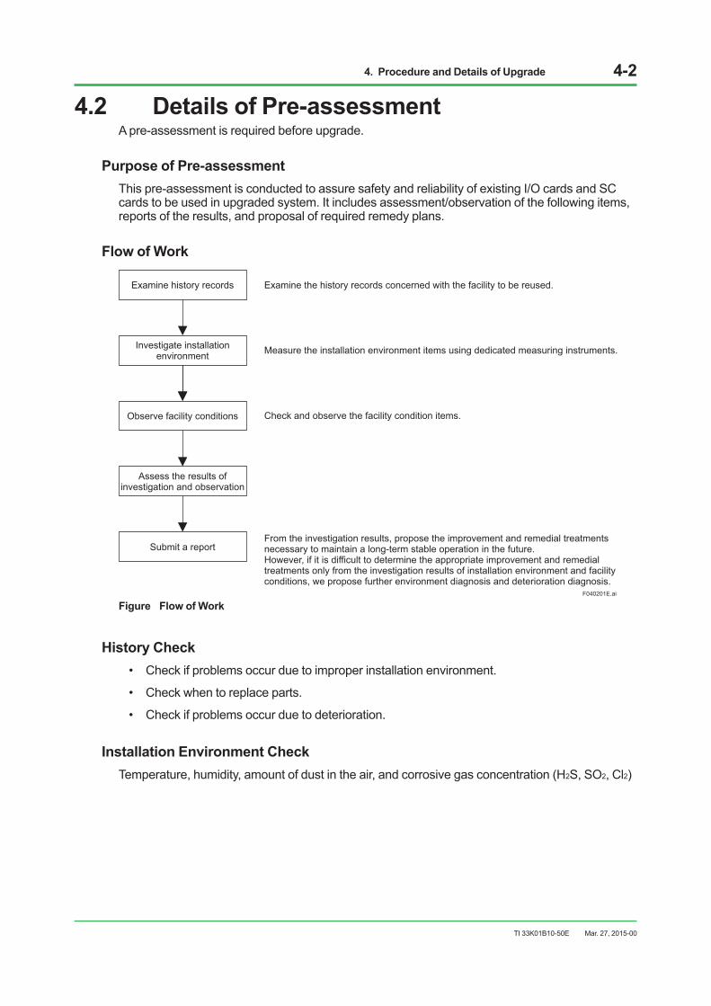
Purpose of Pre-assessmentThis pre-assessment is conducted to assure safety and reliability of existing I/O cards and SC cards to be used in upgraded system. It includes assessment/observation of the following items, reports of the results, and proposal of required remedy plans.
Flow of Work
F040201E.ai
Examine the history records concerned with the facility to be reused.
From the investigation results, propose the improvement and remedial treatments necessary to maintain a long-term stable operation in the future. However, if it is difficult to determine the appropriate improvement and remedial treatments only from the investigation results of installation environment and facility conditions, we propose further environment diagnosis and deterioration diagnosis.
Check and observe the facility condition items.
Measure the installation environment items using dedicated measuring instruments.
Examine history records
Investigate installation environment
Observe facility conditions
Submit a report
Assess the results of investigation and observation
Figure Flow of Work
History Check• Checkifproblemsoccurduetoimproperinstallationenvironment.
• Checkwhentoreplaceparts.
• Checkifproblemsoccurduetodeterioration.
Installation Environment CheckTemperature, humidity, amount of dust in the air, and corrosive gas concentration (H2S, SO2, Cl2)
Mar. 27, 2015-00
4. Procedure and Details of Upgrade 4-3
TI 33K01B10-50E
Facility Conditions Check• Checkinsideandoutsideofthecabinetorotherhousingfordustaccumulationonthefilters
and fans, as well as corrosion on terminal screws.
• Checkthecardsurfacefordustaccumulation.
• Checktheprintpatternsforpeelingandcorrosion.
• Checksolderedpointsforcreep.
• CheckthesurfacesofpartsforcorrosioninICleads.
• Checkcontactareas(foulingofgoldplateconnectors,holesduetocorrosion).
• Checktheredstampforcondensation.
• Checkcoatedareasfordiscolorationandcracks(*1).*1: Only for cards with coating treatment.
Note: Electricalwiringandsignalwiring(toconnectI/Osignalstofielddevices)arenotcheckedbyInstallationEnvironmentCheck.
Mar. 27, 2015-00
4. Procedure and Details of Upgrade 4-4
TI 33K01B10-50E
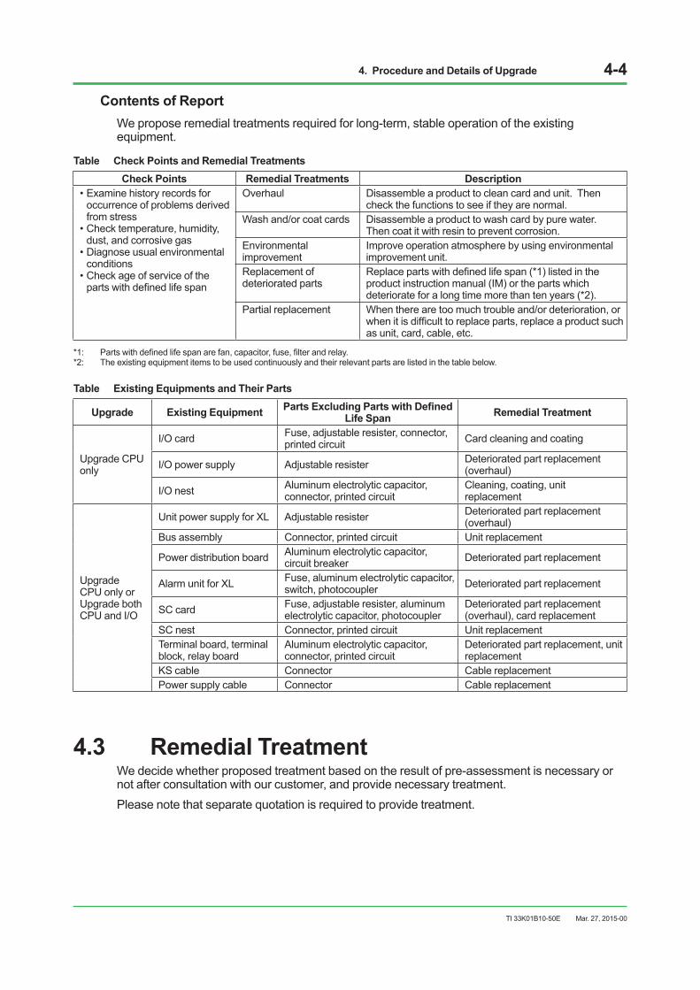
Contents of ReportWe propose remedial treatments required for long-term, stable operation of the existing equipment.
Table Check Points and Remedial TreatmentsCheck Points Remedial Treatments Description
•Examinehistoryrecordsforoccurrence of problems derived from stress
•Checktemperature,humidity,dust, and corrosive gas
•Diagnoseusualenvironmentalconditions
•Checkageofserviceofthepartswithdefinedlifespan
Overhaul Disassemble a product to clean card and unit. Then check the functions to see if they are normal.
Wash and/or coat cards Disassemble a product to wash card by pure water. Then coat it with resin to prevent corrosion.
Environmental improvement
Improve operation atmosphere by using environmental improvement unit.
Replacement of deteriorated parts
Replacepartswithdefinedlifespan(*1)listedintheproduct instruction manual (IM) or the parts which deteriorate for a long time more than ten years (*2).
Partial replacement When there are too much trouble and/or deterioration, or whenitisdifficulttoreplaceparts,replaceaproductsuchas unit, card, cable, etc.
*1: Partswithdefinedlifespanarefan,capacitor,fuse,filterandrelay.*2: The existing equipment items to be used continuously and their relevant parts are listed in the table below.
Table Existing Equipments and Their Parts
Upgrade Existing Equipment PartsExcludingPartswithDefinedLife Span Remedial Treatment
Upgrade CPU only
I/O card Fuse, adjustable resister, connector, printed circuit Card cleaning and coating
I/O power supply Adjustable resister Deteriorated part replacement (overhaul)
I/O nest Aluminum electrolytic capacitor, connector, printed circuit
Cleaning, coating, unit replacement
Upgrade CPU only or Upgrade both CPU and I/O
Unit power supply for XL Adjustable resister Deteriorated part replacement (overhaul)
Bus assembly Connector, printed circuit Unit replacement
Power distribution board Aluminum electrolytic capacitor, circuit breaker Deteriorated part replacement
Alarm unit for XL Fuse, aluminum electrolytic capacitor, switch, photocoupler Deteriorated part replacement
SC card Fuse, adjustable resister, aluminum electrolytic capacitor, photocoupler
Deteriorated part replacement (overhaul), card replacement
SC nest Connector, printed circuit Unit replacementTerminal board, terminal block, relay board
Aluminum electrolytic capacitor, connector, printed circuit
Deteriorated part replacement, unit replacement
KS cable Connector Cable replacementPower supply cable Connector Cable replacement
4.3 Remedial TreatmentWe decide whether proposed treatment based on the result of pre-assessment is necessary or not after consultation with our customer, and provide necessary treatment.Please note that separate quotation is required to provide treatment.
Mar. 27, 2015-00
4. Procedure and Details of Upgrade 4-5
TI 33K01B10-50E
4.4 HardwareModificationandAdditionHISandVnet/IP(*1)thatareinstallednewlyarenotdescribedherein,sincetheyareidentifiedasthe CENTUM VP product.*1: Vnet/IP Interface Card, cable and network switch.
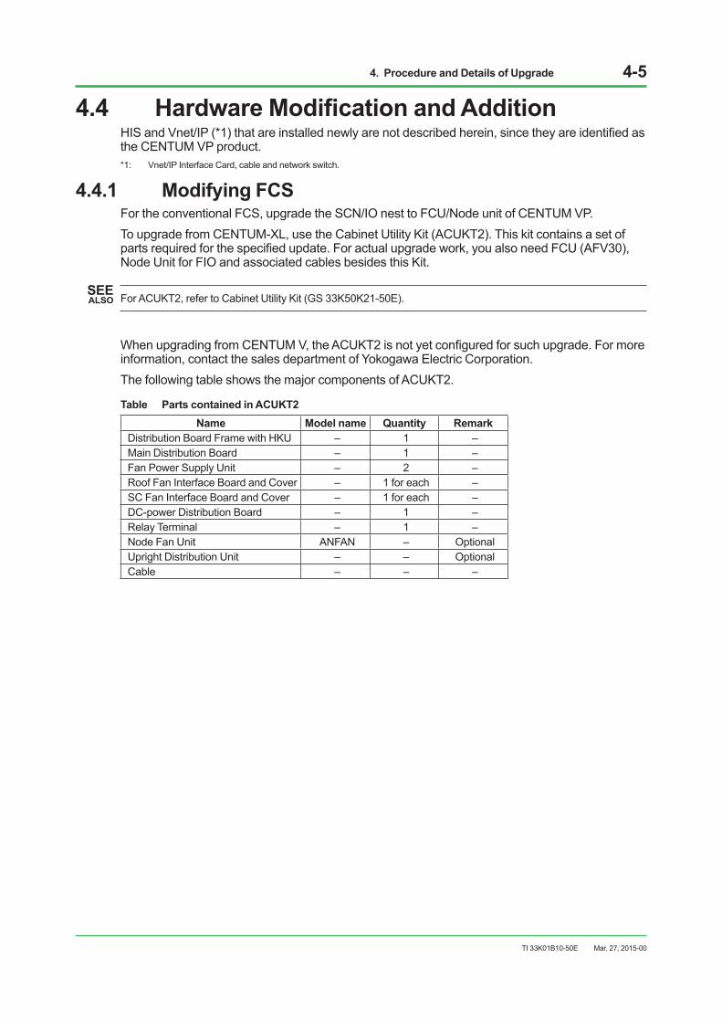
4.4.1 Modifying FCSFor the conventional FCS, upgrade the SCN/IO nest to FCU/Node unit of CENTUM VP. To upgrade from CENTUM-XL, use the Cabinet Utility Kit (ACUKT2). This kit contains a set of partsrequiredforthespecifiedupdate.Foractualupgradework,youalsoneedFCU(AFV30),Node Unit for FIO and associated cables besides this Kit.
SEE ALSO For ACUKT2, refer to Cabinet Utility Kit (GS 33K50K21-50E).
WhenupgradingfromCENTUMV,theACUKT2isnotyetconfiguredforsuchupgrade.Formoreinformation, contact the sales department of Yokogawa Electric Corporation.The following table shows the major components of ACUKT2.
Table Parts contained in ACUKT2Name Model name Quantity Remark
Distribution Board Frame with HKU – 1 –Main Distribution Board – 1 –Fan Power Supply Unit – 2 –Roof Fan Interface Board and Cover – 1 for each –SC Fan Interface Board and Cover – 1 for each –DC-power Distribution Board – 1 –Relay Terminal – 1 –Node Fan Unit ANFAN – OptionalUpright Distribution Unit – – OptionalCable – – –
Mar. 27, 2015-00

4. Procedure and Details of Upgrade 4-6
TI 33K01B10-50E
ThefollowingfigureshowsanupgradeexampleofEFCDwithACUKT2.
SC fan unit
: Parts of ACUKT2
AFV30
PS4(for AC power supply only)
Relayterminal
RearFront
SC fan interface board
ThermistorRoof fan interface boardRoof fan unit
HK interface unit
Node fan unit
Node unit
Primary power distribution unit
Power distributionboard with HKU
Node fan unit
Node unit
Isolation board(for DC power supply only)
DC powerdistribution
board
040401E.ai
Figure An example of EFCD upgrade with ACUKT2
Mar. 27, 2015-00

4. Procedure and Details of Upgrade 4-7
TI 33K01B10-50E
ThefollowingfigureshowsanexampleofaofthreetypesofACUKT2connectionwiththeHKbus.
F040402E.ai
ACUKT2-C
HK bus (existing KHK or AKBHKU cable)Transmission distance: Maximum 100m
ETBC ETBC
AFV30/HKU
ACUKT2-RACUKT2-L
ANB11/BUANB10
Figure 3 Types of ACUKT2
Since the capacity and performance of FCS are remarkably improved, it is now possible to integrate more than one unit of old FCS into one set of FFCS-V when upgrading from CENTUM V and CENTUM-XL. However, note that some additional engineering work may arise since the station/node number must be replaced.
Mar. 27, 2015-00
4. Procedure and Details of Upgrade 4-8
TI 33K01B10-50E
4.4.2 On-siteModification
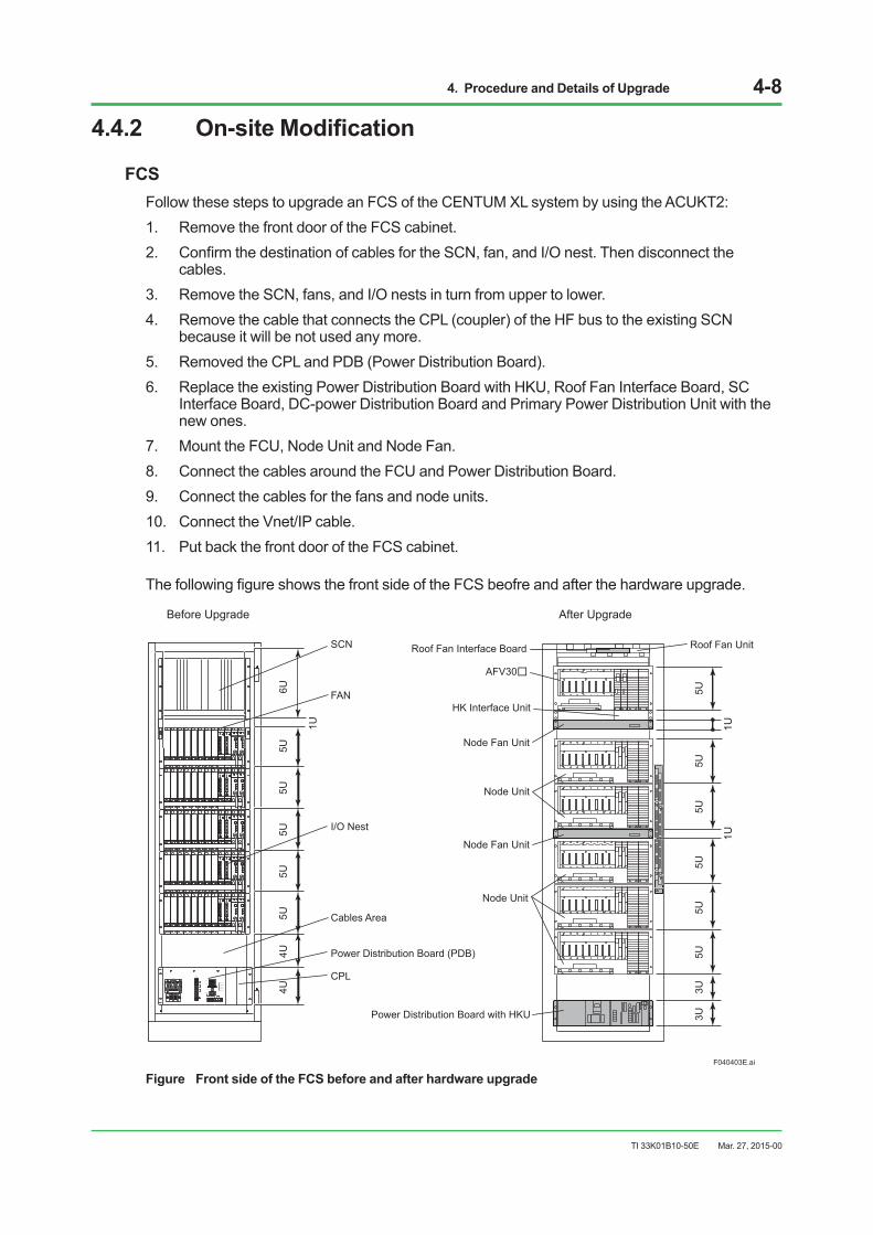
FCSFollow these steps to upgrade an FCS of the CENTUM XL system by using the ACUKT2:1. Remove the front door of the FCS cabinet.2. ConfirmthedestinationofcablesfortheSCN,fan,andI/Onest.Thendisconnectthe
cables.3. Remove the SCN, fans, and I/O nests in turn from upper to lower.4. Remove the cable that connects the CPL (coupler) of the HF bus to the existing SCN
because it will be not used any more.5. Removed the CPL and PDB (Power Distribution Board).6. Replace the existing Power Distribution Board with HKU, Roof Fan Interface Board, SC
Interface Board, DC-power Distribution Board and Primary Power Distribution Unit with the new ones.
7. Mount the FCU, Node Unit and Node Fan.8. Connect the cables around the FCU and Power Distribution Board.9. Connect the cables for the fans and node units.10. Connect the Vnet/IP cable.11. Put back the front door of the FCS cabinet.
ThefollowingfigureshowsthefrontsideoftheFCSbeofreandafterthehardwareupgrade.
F040403E.ai
RDYSELRSP
NESTADRS
MAINT
NORM RDYSELRSP
NESTADRS
MAINT
NORM
V.ADJ
24 V
5 A
5 V
G
V.ADJ
24 V
5 A
5 V
G
21 3 4 5 6 7 8 9 10 11 G
RDYSELRSP
NESTADRS
MAINT
NORM RDYSELRSP
NESTADRS
MAINT
NORM
V.ADJ
24 V
5 A
5 V
G
V.ADJ
24 V
5 A
5 V
G
21 3 4 5 6 7 8 9 10 11 G
RDYSELRSP
NESTADRS
MAINT
NORM RDYSELRSP
NESTADRS
MAINT
NORM
V.ADJ
24 V
5 A
5 V
G
V.ADJ
24 V
5 A
5 V
G
21 3 4 5 6 7 8 9 10 11 G
RDYSELRSP
NESTADRS
MAINT
NORM RDYSELRSP
NESTADRS
MAINT
NORM
V.ADJ
24 V
5 A
5 V
G
V.ADJ
24 V
5 A
5 V
G
21 3 4 5 6 7 8 9 10 11 G
RDYSELRSP
NESTADRS
MAINT
NORM RDYSELRSP
NESTADRS
MAINT
NORM
V.ADJ
24 V
5 A
5 V
G
V.ADJ
24 V
5 A
5 V
G
21 3 4 5 6 7 8 9 10 11 G
SCN
FAN
Cables Area
I/O Nest
6U
1U
5U5U
5U5U
5U4U
4U
Before Upgrade
Power Distribution Board (PDB)
CPLL N
NO
L
TM2AC OUT
CN1
CN2
CN3
125V 1.0AFAN ALM
PS ALM
TEMP ALM
HKU RDY
AUX ALM
TM1
TM3
POWER
N
READY
AUX INNC C + -
L
N
L
N
After Upgrade
1U1U
5U5U
5U5U
5U5U
3U3U
HK Interface Unit
AFV30
Roof Fan Interface Board Roof Fan Unit
Node Fan Unit
Node Unit
Power Distribution Board with HKU
Node Fan Unit
Node Unit
Figure Front side of the FCS before and after hardware upgrade
Mar. 27, 2015-00

4. Procedure and Details of Upgrade 4-9
TI 33K01B10-50E
4.4.3 Upgrading the Existing I/O Card UnitUpgrade of the existing I/O card unit shall be carried out into the I/O modules as shown below.
Table I/O modules after upgrade
Model of existing I/O cards & multiplexer cards Model of I/O modules for Upgrade
KS interface adapter
MAC2 (Analog input/output: 8 points each) AAB841 ATM4A PAC(Pulsetraininput:8points;Analogoutput:8points) AAP849 – VM1 (Analog input: 16 points) AAV141 ATK4A VM2 (Analog input 8 points, Analog output 8 points) AAB841 ATV4A VM4 (Analog output: 16 points) AAV542 ATK4A PM1 (Pulse train input: 16 points) AAP149 – ST2(DI:16points;DO:16points) ADV859(*1) – ST3 (DI, 32 points) ADV159(*1) – ST4 (DO, 32 points) ADV559(*1) – ST5(DI:32points;DO:32points) ADV869(*1) – ST6 (DI, 64 points) ADV169(*1) – ST7 (DO, 64 points) ADV569(*1) – PB5 (Multi-point pushbutton input) ADV159 –
RS4 (RS-232C communication card) ALR111 (Cable also must be changed) –
MX2 (Non-isolated, mV, TC, 32 points) AAT145 (2 modules) – MX3 (Isolated, mV, TC, 16 points) AAT145 – MX4 (Non-isolated, voltage, 32 points) AAV142 (2 modules) ATK4A MX5 (Isolated, voltage, 16 points) (AAV142, non-isolated) (AAV142, non-isolated) ATK4A MX6 (RTD, 32 points) AAR145 (2 modules) – MAC3 (Analog input/Output: 8 points each, for power supply) (*2) – PB6 (Multi-point push button input, 16 points) ADV159 – LD1 (Loop display interface card, CLDU ~ MAC2) (*3) – LCU (Loop communication card, ULDU: 4 units) (*3) (*4) – LCS (Loop communication card, YS80: 8 units) ALR121(*5) –
*1: IntheCENTUMVP,theinput/outputtypeisspecifiedforeachterminal(i.e.,point)ofacontactinput/outputmodule;anoutputtype setting for an odd terminal may take effect on the next even terminal. For details, see GS 33K50F70-50E for Digital I/O Modules (for FIO).
*2: Simply updating to AAB841 is not enough for this setup. Interactive operation with a manual station is necessary.*3: CLDU and ULDU cannot be used. Substitute with a YS instrument.*4: Replace with the communication card of FIO plus YS1000.*5: For connection between an LCS card and a star-type YS instrument, replacement with star type is not possible in updating to
FIO. Since SCIU is currently under order stop, FIO needs to be formed as a daisy chain.
Mar. 27, 2015-00

4. Procedure and Details of Upgrade 4-10
TI 33K01B10-50E
Precautions when upgrading the I/O card• FIO(FieldnetworkI/O)contactI/Osallowthedesignationofoperationmodeonapoint-by-
point basis. The operation mode, which varies with the type of I/O module, is selected by the IOM builder.
• Oddandeventerminalsinthepulsewidthoutputmoduleandthestatusoutput/pulse-widthoutputintegratedmoduleareidenticallydefinedforeverytwoterminals.Ifdifferentdefinitionsareused,changesinwiringarerequired.
• Ifthefollowingcardsareused,theirhardwarespecificationsarechangedtosoftwarespecifications,so,theexistingsystemsshouldbeexamined.
- ST2/ST3/ST4/ST5/ST7cards:OutputvalueswhentheCPUinafieldcontrolstationfails(hold/OFF)
- PB5: Signal detection (rising/falling)
- MX2/MX3: Presence or absence of burnup
• Instrumentsthatallocatetwo-pointconsecutiveDI/Os,suchasswitchinstrumentSIO-22inCENTUM V and CENTUM-XL systems allow crossover allocations between cards, but, FIO in the CENTUM VP system does not provide those allocations. DI/O should be converted to %SW using a sequence table. Valve monitor functions and I/Os of a CI/CO cannot allow crossover allocations between cards either.
Precautions when upgrading the existing SC cardIf the bus of FIO is used, SC cards can upgraded on a card-by-card basis. If the following cards areused,theirhardwarespecificationsarechangedtosoftwarespecifications,so,theexistingsystems should be examined. • EP1:Loadresistance(200Ω/510Ω/1kΩ)andfiltersettings(ON/OFF)
• ET5/ER5/EM1/ES1:Disconnectionprocessing(burnup,burndown,ornone)
• EA5/EH5:Square-rootinputprocessing
Mar. 27, 2015-00
4. Procedure and Details of Upgrade 4-11
TI 33K01B10-50E
4.4.4 InstallationSpecifications
PowerConsumption,CalorificValue,andRushCurrent
FCSPowerconsumptionandcalorificvaluedonotchangebyupgrade,butinrushcurrentincreasesby about 10 % after upgrade.If the power supply system is designed based on the Installation Plan of CENTUM V and CENTUM-XL,itdoesnotneedtobemodifiedsincetheinrushcurrentcanbeabsorbedinthemargin value as described therein.
SEE ALSO For more details, see Appendix 2, “Installation Conditions for CENTUM V and CENTUM-XL.”
FMSPower consumption, heating values and inrush current do not change by upgrade.
Mar. 27, 2015-00
4. Procedure and Details of Upgrade 4-12
TI 33K01B10-50E
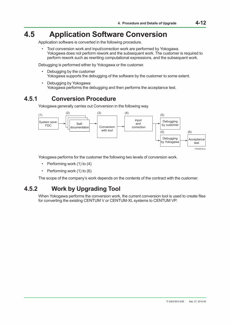
4.5 Application Software Conversion Application software is converted in the following procedure.• Toolconversionworkandinput/correctionworkareperformedbyYokogawa.
Yokogawa does not perform rework and the subsequent work. The customer is required to perform rework such as rewriting computational expressions, and the subsequent work.
Debugging is performed either by Yokogawa or the customer.• Debuggingbythecustomer
Yokogawa supports the debugging of the software by the customer to some extent.
• DebuggingbyYokogawa Yokogawa performs the debugging and then performs the acceptance test.
4.5.1 Conversion ProcedureYokogawa generally carries out Conversion in the following way.
System save FDC Self-
documentation Conversion with tool
input and
correction
Debugging by customer
F040501E.ai
(1) (2) (3) (4) (5)
Debugging by Yokogawa
Acceptance test
(5) (6)
Yokogawa performs for the customer the following two levels of conversion work.• Performingwork(1)to(4)
• Performingwork(1)to(6)
The scope of the company’s work depends on the contents of the contract with the customer.
4.5.2 Work by Upgrading ToolWhenYokogawaperformstheconversionwork,thecurrentconversiontoolisusedtocreatefilesfor converting the existing CENTUM V or CENTUM-XL systems to CENTUM VP.
Mar. 27, 2015-00

4. Procedure and Details of Upgrade 4-13
TI 33K01B10-50E
4.5.3 Handling Tuning ParametersTuning parameter resetting may be required between the existing CENTUM V or CENTUM-XL and the CENTUM VP system. For tuning parameter differences between the existing systems and CENTUM VP, refer to Appendix 3, “Tuning Parameter Differences.”
Items to Be Specially Noted • Two-itemdatachangedtoone-itemdata
Example:Integratedvalue(K2,K3→SUM),batchsetvalue(K8*K9→BSET)
• Normalizeddatachangedtoengineeringunitdata Example: Y-axis of 7PG (PG-L13), X-axis and Y-axis of 7CM-NL (FUNC-VAR), ratio, gain and feedforward gain of 7RS (RATIO)
• Changedalgorithm Example: Derivative term D of PID
IMPORTANT CENTUM VP’s PID function block tends to output its Derivative time calculation value larger, in a short period of time, than CENTUM V or CENUM-XL. It means that CENTUM VP is more responsive to the increase and decrease of an input value or a set point value that are identical.Therefore, when CENTUM V or CENTUM-XL is upgraded to CENTUM VP, reviews of the PID parameters per loop are required. When a Derivative term is 0, the existing Proportional term and Integral term can be directly applicable. In case the Derivative term is something other than 0, considerations to the following points are required. For more details, please contact Yokogawa.• DerivativetermsofCENTUMVorCENTUM-XL,inmostcases,canbedirectlyappliedto
the loops where those values have only little effects.
• OntheloopswhereDerivativetermshavebiginfluence,retuningofthePIDparametersisrequired.
• InputnoisesmaycauseoutputstofluctuatewhentheDerivativetermsarebig.Byusinganinputfilter,theoutputfluctuationcanbecontrolled.
• WhenthePIDactionsofCENTUMVorCENTUM-XLhavetobeinherited,equivalentPIDactions of the existing system can be achieved by using the CENTUM VP’s applications such as CALCU blocks of FCS.
Mar. 27, 2015-00
4. Procedure and Details of Upgrade 4-14
TI 33K01B10-50E
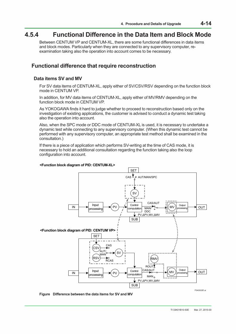
4.5.4 Functional Difference in the Data Item and Block ModeBetween CENTUM VP and CENTUM-XL, there are some functional differences in data items and block modes. Particularly when they are connected to any supervisory computer, re-examination taking also the operation into account comes to be necessary.
Functional difference that require reconstruction
Data items SV and MVFor SV data items of CENTUM-XL, apply either of SV/CSV/RSV depending on the function block mode in CENTUM VP.In addition, for MV data items of CENTUM-XL, apply either of MV/RMV depending on the function block mode in CENTUM VP.AsYOKOGAWAfindsithardtojudgewhethertoproceedtoreconstructionbasedonlyontheinvestigation of existing applications, the customer is advised to conduct a dynamic test taking also the operation into account.Also, when the SPC mode or DDC mode of CENTUM-XL is used, it is necessary to undertake a dynamic test while connecting to any supervisory computer. (When this dynamic test cannot be performed with any supervisory computer, an appropriate test method shall be examined in the consultation.)If there is a piece of application which performs SV-writing at the time of CAS mode, it is necessary to hold an additional consultation regarding the function taking also the loop configurationintoaccount.
F040502E.ai
IN
SET
SUB
OUTInput
processing PV Control computation
SV
OutputprocessingMV
CAS AUT/MAN/SPC
PV,ΔPV,MV,ΔMV
PV,ΔPV,MV,ΔMV
MAN/DDC
CAS/AUT
IN
SET
SUB
OUTInput processing PV
Control computation
SV
OutputprocessingMV
CAS
AUT/MAN
MAN
CAS/AUT
CSV
RSVRCAS
ROUT
RMV
<Function block diagram of PID: CENTUM-XL>
<Function block diagram of PID: CENTUM VP>
Figure Difference between the data items for SV and MV
Mar. 27, 2015-00

4. Procedure and Details of Upgrade 4-15
TI 33K01B10-50E
Backup Mode of CENTUM-XL and Tracking Mode of CENTUM VPThe backup mode (BUM mode) of CENTUM-XL is equivalent to the tracking mode (TRK mode) of CENTUM VP, but the way of transition differs between these modes.In CENTUM-XL, the current mode will shift to the BUM mode from any of the MAN / AUT / CAS modes independently.In CENTUM VP, every mode is a compound mode and both the TRK mode and any of the MAN/AUT/CAS modes can effect concurrently.In CENTUM-XL, any application which uses the local / remote switchover contact input (RL terminal) or has been shifted to the BUM mode according to the sequence, it is necessary to re-examine whether the mode judgment on the tag of CENTUM VP is equivalent or not.Customer is advised to conduct a dynamic test taking also the operation into account.Correction of the subject part shall be carried out only after close discussion with the customer.
F040503E.ai
MAN
AUT
CAS
BUM
(AUT)
(MAN) (CAS)
<Block mode diagram: CENTUM-XL>
<Block mode diagram: CENTUM VP>
TRK (*1)
TRK (*1) TRK (*1)
Figure Difference in the block mode
*1: On CENTUM VP, both the TRK mode and any of the MAN/AUT/CAS modes can effect concurrently.
Example: Where the judgment condition is “Not AUT” in the sequence table of CENTUM-XL, the condition is met when the tag mode is BUM. However, where the judgment condition is “Not AUT” in the sequence table of CENTUM VP, even the same condition is not met when the tag mode is TRK(AUT).
Mar. 27, 2015-00

4. Procedure and Details of Upgrade 4-16
TI 33K01B10-50E
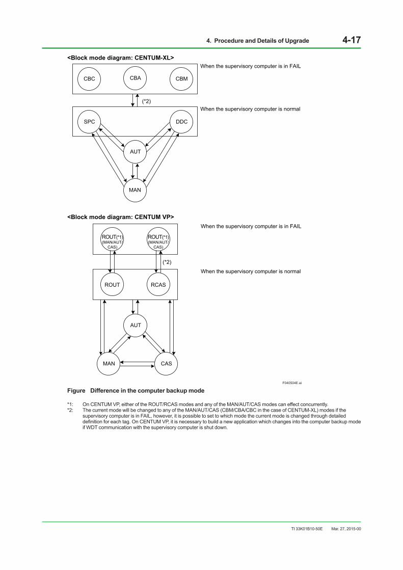
Computer Backup Mode of CENTUM-XL and CENTUM VPThe computer backup mode (CBM / CBA / CBC mode) of CENTUM-XL is equivalent to that of CENTUM VP, but the way of transition differs between them.In CENTUM-XL, the current mode will shift to the CBM / CBA / CBC mode which is independent from any of the MAN / AUT / CAS modes.In CENTUM VP, every mode is a compound mode and either of the RCAS / ROUT modes and any of the MAN / AUT / CAS modes can effect concurrently.CENTUM-XL performs WDT communication with the supervisory computer, and the system switch %SW0064 will be turned to ON if the supervisory computer fails (FAIL). When %SW0064 is turned to ON, the system will change into the computer backup mode (CBM / CBA / CBC mode). However, CENTUM VP has no such corresponding function, it is necessary to newly build an equivalent application.Where there is an application which has been changed into the SPC / DDC mode with CENTUM-XL, and if it performs WDT communication with the supervisory computer, re-examination whether the mode judgment on the tag of CENTUM VP is equivalent is required.Customer is requested to conduct a dynamic test with the supervisory computer taking also the operation into account.(When this dynamic test cannot be performed with any supervisory computer, an appropriate test method shall be discussed in the consultation.)Correction of the subject part shall be carried out only after close discussion with the customer.Example: Where the judgment condition is “Not AUT” in the sequence table of CENTUM-XL, the
condition is met when the tag mode is CBA. However, where the judgment condition is “Not AUT” in the sequence table of CENTUM VP, even the same condition is not met if the tag mode is RCAS(AUT).
Mar. 27, 2015-00
4. Procedure and Details of Upgrade 4-17
TI 33K01B10-50E
F040504E.ai
AUT
MAN CAS
RCASROUT
ROUT(*1)(MAN/AUT/
CAS)
ROUT(*1)(MAN/AUT/
CAS)
When the supervisory computer is normal
When the supervisory computer is in FAIL
<Block mode diagram: CENTUM VP>
(*2)
MAN
AUT
DDCSPC
<Block mode diagram: CENTUM-XL>
CBMCBC CBA
When the supervisory computer is normal
When the supervisory computer is in FAIL
(*2)
Figure Difference in the computer backup mode
*1: On CENTUM VP, either of the ROUT/RCAS modes and any of the MAN/AUT/CAS modes can effect concurrently.*2: The current mode will be changed to any of the MAN/AUT/CAS (CBM/CBA/CBC in the case of CENTUM-XL) modes if the
supervisory computer is in FAIL, however, it is possible to set to which mode the current mode is changed through detailed definitionforeachtag.OnCENTUMVP,itisnecessarytobuildanewapplicationwhichchangesintothecomputerbackupmodeif WDT communication with the supervisory computer is shut down.
Mar. 27, 2015-00

4. Procedure and Details of Upgrade 4-18
TI 33K01B10-50E
4.6 On-site System Operations Check Conducton-sitesystemfinalcheckswhileadjustingtuningparametersandcheckingsystemoperation timing.
4.7 Maintenance After Upgrade
Life of Parts Used in Upgraded HardwareSystem hardware contains limited-life parts, which must be replaced periodically. For preventive maintenance, the table below lists the recommended replacement cycles.
Control equipment (AFV30, ANB10)
Table Limited-life Parts Used in Control Equipment
Part name Part No. Recommended
replacement cycle
Applicable model Replaceable by user(*2) Remarks
AFV30 ANB10
Power Supply Module (100-120V AC) PW481 8 years X X X Average ambient temp.(*1),
40°C or lowerPower Supply Module (220-240V AC) PW482 8 years X X X Average ambient temp.(*1),
40°C or lowerPower Supply Module (24V DC) PW484 8 years X X X Average ambient temp.(*1),
40°C or lower
Battery Pack S9548FA
3 years X – X Average ambient temp.(*1), 30°C or lower
1.5 years X – X Average ambient temp.(*1), 40°C or lower
9 months X – X Average ambient temp.(*1), 50°C or lower
Electrolytic Capacitor (inside of Power Supply Module)
(PW481) 8 years X XOverhaul of Power Supply Module is required.(PW482) 8 years X X
(PW484) 8 years X XBuilt-in Fuse in Power Supply Unit
S9109VK 8 years X X For PW481, PW482A1546EF 8 years X X For PW484
Fan Power Supply Unit (100-200, 220-240VAC) S9618FA 8 years (*3) – X Average ambient temp.(*1),
40°C or lowerFan Power Supply Unit (24V DC) S9618FA 8 years (*3) – X Average ambient temp.(*1),
40°C or lowerNode Fan AIP611 8 years (*3) – X For Node Fan Unit
*1: Average ambient temperature varies with the environment in which FCS is installed. Where FCS is installed in a cabinet, an average ambient temperature indicates that not outside but inside the cabinet.
*2: In the “Replaceable by user” column of this table, the parts marked with ‘X’ can be replaced by users. Do not replace those unmarked. Be suretoasktheYokogawaserviceofficetoreplacethepartsunmarked.
*3: This is a part contained in the Cabinet Utility Kit, ACUKT2.
Maintenance ServiceIt is recommended that you make an Annual Maintenance Service Contract to assure long-term, stable use of upgraded equipment and existing I/O cards and SC cards to be used after upgrade.If we have taken remedial action for your systems according to pre-assessment, you can choose one from two types of annual maintenance services: standard contract (for 9AM-to-5PM support) and full-service contract (for 24-hour support). These service contracts are also available for the CENTUM VP. If we haven’t, on-demand maintenance service is available.
Mar. 27, 2015-00
5. System Functions After Upgrade 5-1
TI 33K01B10-50E
5. System Functions After Upgrade
5.1 System Overview5.1.1 Overall Control Functions
This section describes the enhancements of the overall control functions in FCS that is upgraded to FFCS-V, hereinafter referred to as “Upgraded FCS.”
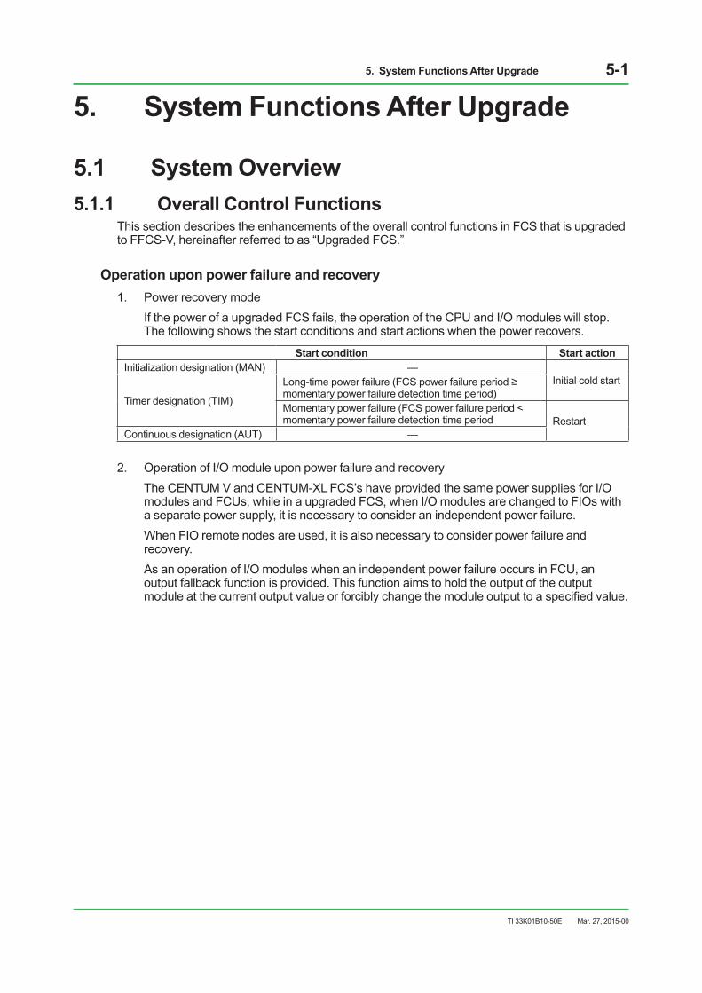
Operation upon power failure and recovery1. Power recovery mode If the power of a upgraded FCS fails, the operation of the CPU and I/O modules will stop.
The following shows the start conditions and start actions when the power recovers.
Start condition Start action Initialization designation (MAN) —
Initial cold start
Timer designation (TIM)
Long-timepowerfailure(FCSpowerfailureperiod≥momentary power failure detection time period) Momentary power failure (FCS power failure period < momentary power failure detection time period Restart
Continuous designation (AUT) —
2. Operation of I/O module upon power failure and recovery The CENTUM V and CENTUM-XL FCS’s have provided the same power supplies for I/O
modules and FCUs, while in a upgraded FCS, when I/O modules are changed to FIOs with a separate power supply, it is necessary to consider an independent power failure.
When FIO remote nodes are used, it is also necessary to consider power failure and recovery.
As an operation of I/O modules when an independent power failure occurs in FCU, an output fallback function is provided. This function aims to hold the output of the output moduleatthecurrentoutputvalueorforciblychangethemoduleoutputtoaspecifiedvalue.
Mar. 27, 2015-00
5. System Functions After Upgrade 5-2
TI 33K01B10-50E
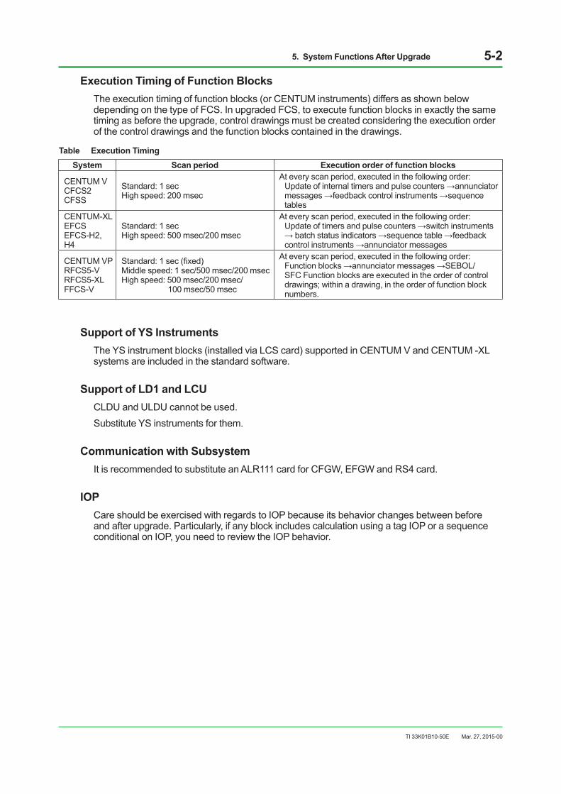
Execution Timing of Function BlocksThe execution timing of function blocks (or CENTUM instruments) differs as shown below depending on the type of FCS. In upgraded FCS, to execute function blocks in exactly the same timing as before the upgrade, control drawings must be created considering the execution order of the control drawings and the function blocks contained in the drawings.
Table Execution TimingSystem Scan period Execution order of function blocks
CENTUM V CFCS2 CFSS
Standard: 1 sec High speed: 200 msec
At every scan period, executed in the following order: Updateofinternaltimersandpulsecounters→annunciatormessages→feedbackcontrolinstruments→sequencetables
CENTUM-XL EFCS EFCS-H2, H4
Standard: 1 sec High speed: 500 msec/200 msec
At every scan period, executed in the following order: Updateoftimersandpulsecounters→switchinstruments→batchstatusindicators→sequencetable→feedbackcontrolinstruments→annunciatormessages
CENTUM VP RFCS5-V RFCS5-XL FFCS-V
Standard:1sec(fixed)Middle speed: 1 sec/500 msec/200 msec High speed: 500 msec/200 msec/ 100 msec/50 msec
At every scan period, executed in the following order: Functionblocks→annunciatormessages→SEBOL/SFC Function blocks are executed in the order of control drawings;withinadrawing,intheorderoffunctionblocknumbers.
Support of YS InstrumentsThe YS instrument blocks (installed via LCS card) supported in CENTUM V and CENTUM -XL systems are included in the standard software.
Support of LD1 and LCUCLDU and ULDU cannot be used. Substitute YS instruments for them.
Communication with SubsystemIt is recommended to substitute an ALR111 card for CFGW, EFGW and RS4 card.
IOPCare should be exercised with regards to IOP because its behavior changes between before and after upgrade. Particularly, if any block includes calculation using a tag IOP or a sequence conditional on IOP, you need to review the IOP behavior.
Mar. 27, 2015-00
5. System Functions After Upgrade 5-3
TI 33K01B10-50E
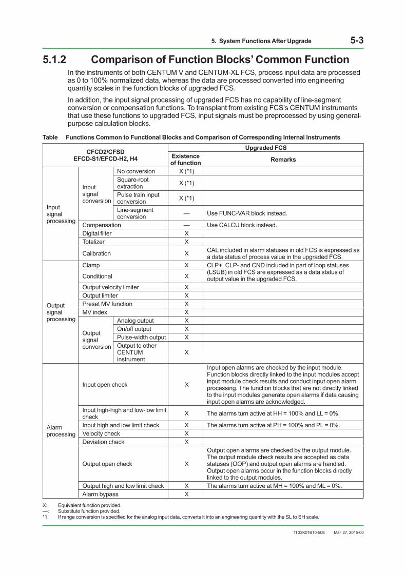
5.1.2 Comparison of Function Blocks’ Common FunctionIn the instruments of both CENTUM V and CENTUM-XL FCS, process input data are processed as 0 to 100% normalized data, whereas the data are processed converted into engineering quantity scales in the function blocks of upgraded FCS.In addition, the input signal processing of upgraded FCS has no capability of line-segment conversion or compensation functions. To transplant from existing FCS’s CENTUM instruments that use these functions to upgraded FCS, input signals must be preprocessed by using general-purpose calculation blocks.
Table Functions Common to Functional Blocks and Comparison of Corresponding Internal Instruments
CFCD2/CFSD EFCD-S1/EFCD-H2, H4
Upgraded FCS Existence of function Remarks
Input signal processing
Input signal conversion
No conversion X (*1) Square-root extraction X (*1)
Pulse train input conversion X (*1)
Line-segment conversion — Use FUNC-VAR block instead.
Compensation — Use CALCU block instead. Digitalfilter X Totalizer X
Calibration X CAL included in alarm statuses in old FCS is expressed as a data status of process value in the upgraded FCS.
Output signal processing
Clamp X CLP+, CLP- and CND included in part of loop statuses (LSUB) in old FCS are expressed as a data status of output value in the upgraded FCS.Conditional X
Output velocity limiter X Output limiter X Preset MV function X MV index X
Output signal conversion
Analog output X On/off output X Pulse-width output X Output to other CENTUM instrument
X
Alarm processing
Input open check X
Input open alarms are checked by the input module. Function blocks directly linked to the input modules accept input module check results and conduct input open alarm processing. The function blocks that are not directly linked to the input modules generate open alarms if data causing input open alarms are acknowledged.
Input high-high and low-low limit check X The alarms turn active at HH = 100% and LL = 0%.
Input high and low limit check X The alarms turn active at PH = 100% and PL = 0%. Velocity check X Deviation check X
Output open check X
Output open alarms are checked by the output module. The output module check results are accepted as data statuses (OOP) and output open alarms are handled. Output open alarms occur in the function blocks directly linked to the output modules.
Output high and low limit check X The alarms turn active at MH = 100% and ML = 0%. Alarm bypass X
X: Equivalent function provided.—: Substitute function provided.*1: Ifrangeconversionisspecifiedfortheanaloginputdata,convertsitintoanengineeringquantitywiththeSLtoSHscale.
Mar. 27, 2015-00

5. System Functions After Upgrade 5-4
TI 33K01B10-50E
5.1.3 Comparison of Continuous Control FunctionThe table below shows a comparison of the continuous control function models between the CENTUM V, CENTUM-XL, and CENTUM VP systems.
Table Comparison of Continuous Control Function
Block type Model DescriptionCENTUM V CENTUM-XL Upgraded FCS Input indicator
7PV PVI PVI Input indicator 7PV-DV PVI-DV PVI-DV Input indicator with deviation alarms
Controller
7DC-D5
PID PID PID controller
The same control action can be obtained by changing the control algorithm and gap action using the builder.
7DC-N5 7DC-D6 7DC-N6
– PI-HLD PI-HLD Sampling PI controller 7DC-B5 PID-BSW PID-BSW Controller with batch switch 7DC-C2 ONOFF ONOFF 2-position on/off controller 7DC-C3 ONOFF-G ONOFF-G 3-position on/off controller 7DC-C9 PID-TP PID-TP Time-proportional on/off controller 7DC-D3 PD-MR PD-MR Proportional controller 7DC-D9 PI-BLEND PI-BLEND Blending controller
– PID-STC PID-STC Self-tuning PID controller
Manual operation unit
7ML-ND MLD MLD Manual loader 7ML MLD-PVI MLD-PVI Manual loader with input indicator 7ML-SW
MLD-SW MLD-SW Manual loader with auto/man switch7ML-XN 7MC-C2 MC-2 MC-2 2-position motor control unit 7MC-C3 MC-3 MC-3 3-position motor control unit
Signal set unit
7RS RATIO RATIO Ratio set unit 7PG
PG-L13 PG-L13
6-zone program set unit (Substitute PG-L13.) 7PG-BR 13-zone program set unit 7PG-SP PG-S13 13-step program set unit (Substitute PG-L13.) 7BS BSETU
BSETU-2 Batch set unit
– BSETU-2 Batchsetunitforflowmeasurement– BSETU-3 BSETU-3 Batch set unit for weight measurement
Signal limiter 7RL VELLIM VELLIM Velocity limiter
Signal selector
7SS-S-H/M/L SS-H/M/L SS-H/M/L Signal selector 7SS-A-H/M/L AS-H/M/L AS-H/M/L Autoselector 7RD SS-DUAL SS-DUAL Dual signal selector
Data link 7SL-DT SDL
ADL Station data link
– SDL-2 Station data link for setting by communication
YS80
SLCD SLCD SLCD SLCD indicating controller SLPC SLPC SLPC SLPC programmable controller SLMC SLMC SLMC SLMC programmable controller with pulse-width output
SMST-111 SMST-111 SMST-111 SMST-111 auto/manual station with push-button setpoint setting
SMST-121 SMST-121 SMST-121 SMST-121 auto/manual station with manipulated output lever
SMRT SMRT SMRT SMRT ratio set unit
YS BCS
SBSD SBSD SBSD SBSD batch set unit SLCC SLCC SLCC SLCC blending controller SLBC SLBC SLBC SLBC batch controller STLD STLD STLD STLD totalizer
Alarm – ALM-R ALM-R Representative alarm unit
Mar. 27, 2015-00

5. System Functions After Upgrade 5-5
TI 33K01B10-50E
Interstation CommunicationsIt is recommended that the control stations closely related to each other via station data link be collectively upgraded to CENTUM VP at the same time. For upgrade work methods, see Section 5.2,“UpgradeSpecifications.”Ifinter-stationcommunicationmustbeperformedforvariousreasons between a “Non-upgraded FCS” and “Upgraded FCS,” the setup must be changed.Communication between “Upgraded FCS” and “Non-upgraded stations” is realized using the link block (ADL) between CENTUM VP stations, through which data reading and writing are conducted from the CENTUM VP. CENTUM V and CENTUM-XL use data buffer to accept the data for data processing.Upgraded FCS (CENTUM VP):1. Specify communication from “Upgraded FCS” to “Non-upgraded stations.” On the control
drawingbuilderofCENTUMVP,describethetagnameanddataidentifierof“Non-upgradedstations” of the communication target as the connection target of the “IN” and “OUT” terminals of the function block. ADL is built automatically, and communication from “Upgraded FCS” to “Non-upgraded stations”isspecified.
IMPORTANTADL communications by CI/CO cannot be made because signed integer data are changed to unsignedintegerdatawhenhandlingthefirstbitof16bits.Asanothercorrectivemeasure,itisnecessary to use an appropriate computational expression.
When non-upgraded station is CENTUM V1. If a communication error of “Non-upgraded stations” and “Upgraded FCS” is assigned to the
annunciator or interlock, cancel it.2. Delete communication from “Non-upgraded stations” to “Upgraded FCS” using the station
connection unit screen. (Recommended) (If the communication setup is not to be deleted, a communication error occurs at “Non-upgraded stations”. However, there is no problem regarding control operation and communication performance.)
When non-upgraded station is CENTUM-XL1. Change the setup of the inter-station communication instruments in the feedback control
builder as follows. Command switch SV=2 (Data Reference and Setting is performed, communication is not.)
Mar. 27, 2015-00

5. System Functions After Upgrade 5-6
TI 33K01B10-50E
The table below shows a comparison of the detailed functions of the continuous control function between the CENTUM V, CENTUM-XL, and CENTUM VP systems.
Table Comparison of Details of Regulatory Control Functions
Function Items of Functions Compared CFCD2/CFSD EFCD-S1/H2, H4 Upgraded FCS
Off-scan and service-off (O/S)
Existence of transmission
No transmission of statuses to other instruments linked to instruments set to off-scan.
Service-off (O/S) mode can even be transmitted to function blocks linked to the relevant block.
Possibility of data read/write
Possible data read/write to relevant instruments from other instruments set to off-scan
In service-off (O/S) states, data read/write to the relevant block from other function blocks are impossible.
Mode when regulatory control instruments are changed from off-scan mode to on-scan mode in sequence control
Returns to the mode immediately before changing to off-scan mode
Mode (e.g., AUT/MAN) should be specified.
CAL CAL handling Handled as an alarm Handled as data status
Scale high and low limits
Possibility of reverse setting of scale high/low limits (SH/SL)
Scale values smaller than scale low limit can be set to scale high limit.
Scale values smaller than scale low limit cannot be set to scale high limit. A reverse-scale display can be applied.
Connection terminal
Terminal Table Comparison of Connection Terminal Functions
Chain connection One OUT terminal allows terminal connections to multiple low-order instruments.
Cascade signal distributor blocks (FOUT) allow connections to multiple low-order blocks.
Processing when checking IOP
PV value overshooting Depends on input signal states
FCS provides group setting Depends on function blocks
Mar. 27, 2015-00
5. System Functions After Upgrade 5-7
TI 33K01B10-50E
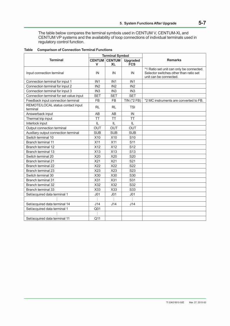
The table below compares the terminal symbols used in CENTUM V, CENTUM-XL and CENTUM VP systems and the availability of loop connections of individual terminals used in regulatory control function.
Table Comparison of Connection Terminal Functions
Terminal Terminal Symbol
RemarksCENTUM V
CENTUM XL
Upgraded FCS
Input connection terminal IN IN IN *1 Ratio set unit can only be connected. Selector switches other than ratio set unit can be connected.
Connection terminal for input 1 IN1 IN1 IN1 Connection terminal for input 2 IN2 IN2 IN2 Connection terminal for input 3 IN3 IN3 IN3 Connection terminal for set value input SET SET SET Feedback input connection terminal FB FB TIN (*2 FB) *2 MC instruments are converted to FB. REMOTE/LOCAL status contact input terminal RL RL TSI
Answerback input AB AB IN Thermal trip input TT TT TT Interlock input IL IL IL Output connection terminal OUT OUT OUT Auxiliary output connection terminal SUB SUB SUB Switch terminal 10 X10 X10 S10 Branch terminal 11 X11 X11 S11 Branch terminal 12 X12 X12 S12 Branch terminal 13 X13 X13 S13 Switch terminal 20 X20 X20 S20 Branch terminal 21 X21 X21 S21 Branch terminal 22 X22 X22 S22 Branch terminal 23 X23 X23 S23 Switch terminal 30 X30 X30 S30 Branch terminal 31 X31 X31 S31 Branch terminal 32 X32 X32 S32 Branch terminal 33 X33 X33 S33 Set/acquired data terminal 1 J01 J01 J01
Set/acquired data terminal 14 J14 J14 J14 Set/acquired data terminal 1 Q01
Set/acquired data terminal 11 Q11
Mar. 27, 2015-00

5. System Functions After Upgrade 5-8
TI 33K01B10-50E
5.1.4 Comparison of Sequence Control FunctionUpgraded FCS have no computational expressions (NCLxxx, %CLxxx) for sequence control. If these functions are used, a one-shot driven, general-purpose calculation block (CALCU) should be used.
Table Comparison of Sequence Control Function
Block type Model DescriptionCENTUM V CENTUM-XL Upgraded FCS
Sequence table
NST %ST
ST16 Total of 64 input and output signals and 32 rules
M_ST16 Total of 96 signals (32-64 input and 32-64 output signals) and 32 rules (*1)
L-ST16 64 input and 64 output signals, and 32 rules – – ST16E For extending rules to 32 – – M_ST16E For extending rules to 32 (for M_ST16) (*1)– – L_ST16E For extending rules to 32 (for L_ST16) (*1)
Switch instrument
– SI-1 SI-1 1-input switch instrument – SI-2 SI-2 2-input switch instrument – SO-1 SO-1 1-output switch instrument – SO-2 SO-2 2-output switch instrument – SIO-11 SIO-11 1-input, 1-output switch instrument – SIO-12 SIO-12 1-input, 2-output switch instrument – SIO-21 SIO-21 2-input, 1-output switch instrument – SIO-22 SIO-22 2-input, 2-output switch instrument – SIO-12P SIO-12P 1-input, 2-pulse-output switch instrument – SIO-22P SIO-22P 2-input, 2-pulse-output switch instrument
Sequence auxiliary
NTM %TM TM Internal timer (with tag name)
NCT %CT CTS Internal counter (with tag name) CTP Pulse train counter (with tag name)
NCI %CI CI Code input (with tag name) NCO %CO CO Code output (with tag name) NRL %RL RL Relational expression (with tag name)
NCL %CL CALCU Computational expression (In Upgraded FCS, the function is covered by CALCU is one-shot driven.)
– %RM RS Resource scheduler Valve monitor (*2) (*2) VLVM Valve monitor Batch status indicator – BSI BSI Batch status indicator (A function block of the faceplate
function)
*1: Can be used if upgrade type database (with sequence table with expanded number of signals) is selected.*2: Although no element name is given, a valve output monitoring function exists.
Mar. 27, 2015-00
5. System Functions After Upgrade 5-9
TI 33K01B10-50E
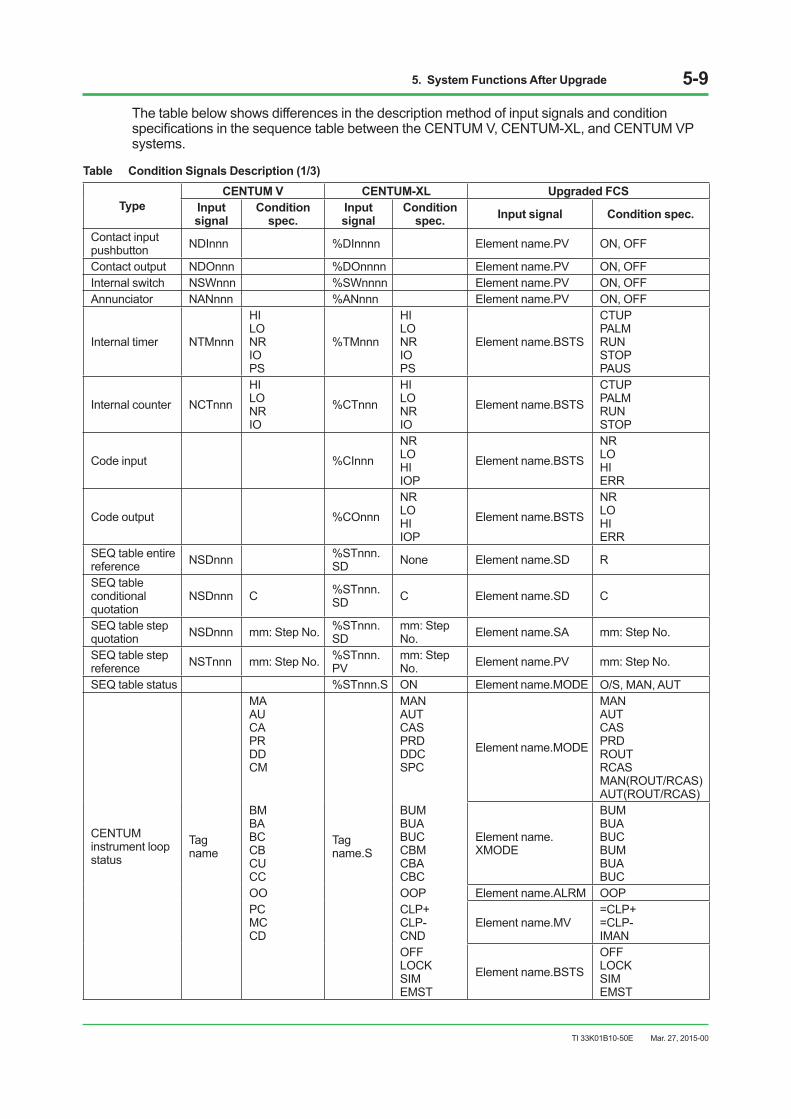
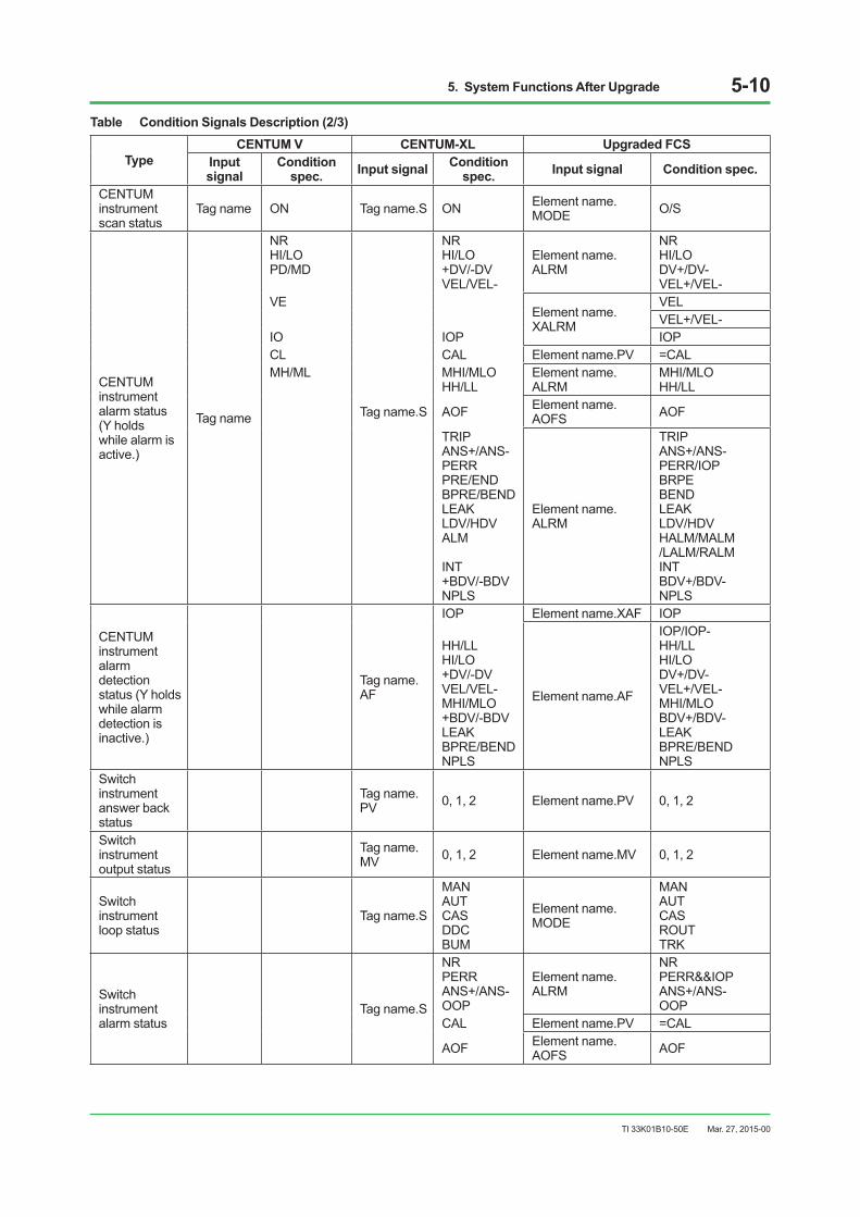
The table below shows differences in the description method of input signals and condition specificationsinthesequencetablebetweentheCENTUMV,CENTUM-XL,andCENTUMVPsystems.
Table Condition Signals Description (1/3)
Type CENTUM V CENTUM-XL Upgraded FCS
Input signal
Condition spec.
Input signal
Condition spec. Input signal Condition spec.
Contact input pushbutton NDInnn %DInnnn Element name.PV ON, OFF
Contact output NDOnnn %DOnnnn Element name.PV ON, OFF Internal switch NSWnnn %SWnnnn Element name.PV ON, OFF Annunciator NANnnn %ANnnn Element name.PV ON, OFF
Internal timer NTMnnn
HI LO NR IO PS
%TMnnn
HI LO NR IO PS
Element name.BSTS
CTUP PALM RUN STOP PAUS
Internal counter NCTnnn
HI LO NR IO
%CTnnn
HI LO NR IO
Element name.BSTS
CTUP PALM RUN STOP
Code input %CInnn
NR LO HI IOP
Element name.BSTS
NR LO HI ERR
Code output %COnnn
NR LO HI IOP
Element name.BSTS
NR LO HI ERR
SEQ table entire reference NSDnnn %STnnn.
SD None Element name.SD R
SEQ table conditional quotation
NSDnnn C %STnnn.SD C Element name.SD C
SEQ table step quotation NSDnnn mm: Step No. %STnnn.
SD mm: Step No. Element name.SA mm: Step No.
SEQ table step reference NSTnnn mm: Step No. %STnnn.
PV mm: Step No. Element name.PV mm: Step No.
SEQ table status %STnnn.S ON Element name.MODE O/S, MAN, AUT
CENTUM instrument loop status
Tag name
MA AU CA PR DD CM
Tag name.S
MAN AUT CAS PRD DDC SPC
Element name.MODE
MAN AUT CAS PRD ROUT RCAS MAN(ROUT/RCAS) AUT(ROUT/RCAS)
BM BA BC CB CU CC
BUM BUA BUC CBM CBA CBC
Element name.XMODE
BUM BUA BUC BUM BUA BUC
OO OOP Element name.ALRM OOP PC MC CD
CLP+CLP-CND
Element name.MV =CLP+ =CLP-IMAN
OFF LOCK SIM EMST
Element name.BSTS
OFF LOCK SIM EMST
Mar. 27, 2015-00
5. System Functions After Upgrade 5-10
TI 33K01B10-50E
Table Condition Signals Description (2/3)
Type CENTUM V CENTUM-XL Upgraded FCS
Input signal
Condition spec. Input signal Condition
spec. Input signal Condition spec.
CENTUM instrument scan status
Tag name ON Tag name.S ON Element name.MODE O/S
CENTUM instrument alarm status (Y holds while alarm is active.)
Tag name
NR HI/LO PD/MD
NR HI/LO +DV/-DV VEL/VEL-
Element name.ALRM
NR HI/LO DV+/DV-VEL+/VEL-
VE Element name.XALRM
VEL VEL+/VEL-
IO IOP IOP CL CAL Element name.PV =CAL MH/ML MHI/MLO
HH/LL Element name.ALRM
MHI/MLO HH/LL
Tag name.S AOF Element name.AOFS AOF
TRIP ANS+/ANS-PERR PRE/END BPRE/BEND LEAK LDV/HDV ALM
INT +BDV/-BDV NPLS
Element name.ALRM
TRIP ANS+/ANS-PERR/IOP BRPE BEND LEAK LDV/HDV HALM/MALM /LALM/RALM INT BDV+/BDV-NPLS
CENTUM instrument alarm detection status (Y holds while alarm detection is inactive.)
Tag name.AF
IOP Element name.XAF IOP
HH/LL HI/LO +DV/-DV VEL/VEL-MHI/MLO +BDV/-BDV LEAK BPRE/BEND NPLS
Element name.AF
IOP/IOP-HH/LL HI/LO DV+/DV-VEL+/VEL-MHI/MLO BDV+/BDV-LEAK BPRE/BEND NPLS
Switch instrument answer back status
Tag name.PV 0, 1, 2 Element name.PV 0, 1, 2
Switch instrument output status
Tag name.MV 0, 1, 2 Element name.MV 0, 1, 2
Switch instrument loop status
Tag name.S
MAN AUT CAS DDC BUM
Element name.MODE
MAN AUT CAS ROUT TRK
Switch instrument alarm status
Tag name.S
NR PERR ANS+/ANS-OOP
Element name.ALRM
NR PERR&&IOP ANS+/ANS-OOP
CAL Element name.PV =CAL
AOF Element name.AOFS AOF
Mar. 27, 2015-00
5. System Functions After Upgrade 5-11
TI 33K01B10-50E
Table Condition Signals Description (3/3)
Type CENTUM V CENTUM-XL Upgraded FCS
Input signal
Condition spec. Input signal Condition
spec. Input signal Condition spec.
Batch status indicator
Tag name.PV 0 to 15 Element name.SV 1 to 99
Tag name.SV 0, 1, 2 Element name.
PV01 to PV10 0, 1
Relational expression NRLnnn
EQ GT GE LT LE
%RLnnn
EQ GT GE LT LE
Element name.X01 to X16
EQ GT GE LT LE AND
Resource scheduler
%RMnnn.RQ 1 to 32 Element name.
RQ01 to RQ32 0, 1
%RMnnn.PM 1 to 32 Element name.
PM01 to PM32 0, 1
Thefollowingshowsinputsignalsandconditionspecificationsthatwerenewlyaddedtoaupgraded FCS.
Table Signal Operation
TypeCondition signal column Condition
rule ConditionInput signal Condition spec.
Mode of function block Element name.XMODE
BUM Y Block mode is ROUT(MAN) or
RCAS(MAN)
N Block mode is neither ROUT(MAN) nor RCAS(MAN)
BUA Y Block mode is ROUT(AUT) or RCAS(AUT)
N Block mode is neither ROUT(AUT) nor RCAS(AUT)
BUC Y Block mode is ROUT(CAS) or RCAS(CAS)
N Block mode is neither ROUT(CAS) nor RCAS(CAS)
Alarm status of function block Element name.XALPM
IOP Y Alarm status is IOP or IOP-N Alarm status is neither IOP nor IOP-
VEL Y Alarm status is VEL+ or VEL-N Alarm status is neither VEL+ nor VEL-
Alarm detection status of function block Element name.XAF IOP
Y Do not detect IOP or IOP- alarm. N Detect IOP and IOP- alarms.
Mar. 27, 2015-00
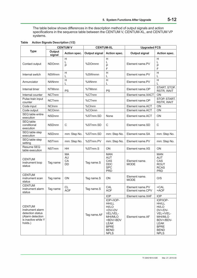
5. System Functions After Upgrade 5-12
TI 33K01B10-50E
The table below shows differences in the description method of output signals and action specificationsinthesequencetablebetweentheCENTUMV,CENTUM-XL,andCENTUMVPsystems.
Table Action Signals Description (1/2)
Type CENTUM V CENTUM-XL Upgraded FCS
Output signal Action spec. Output signal Action spec. Output signal Action spec.
Contact output NDOnnn
H L P %DOnnnn
H L P F
Element name.PV
H L P F
Internal switch NSWnnn H L %SWnnnn H
L Element name.PV H L
Annunciator NANnnn H L %ANnnn H
L Element name.PV H L
Internal timer NTMnnn PS %TMnnn PS Element name.OP START, STOP, RSTR, WAIT
Internal counter NCTnnn %CTnnn Element name.XACT ON Pulse train input counter NCTnnn %CTnnn Element name.OP STOP, START,
RSTR, WAIT Code input NCInnn %CInnn Element name.ACT ON Code output NCOnnn %COnnn Element name.ACT ON SEQ table entire execution NSDnnn %STnnn.SD None Element name.ACT ON
SEQ table conditional execution
NSDnnn C %STnnn.SD C Element name.SD C
SEQ table step execution NSDnnn mm: Step No. %STnnn.SD mm: Step No. Element name.SA mm: Step No.
SEQ table step setting NSTnnn mm: Step No. %STnnn.PV mm: Step No. Element name.PV mm: Step No.
Resume SEQ table execution NSTnnn HH %STnnn.S ON Element name.XS ON
CENTUM instrument loop status
Tag name
MA AU CA DD Tag name.S
MAN AUT CAS DDC SPC PRD
Element name.MODE
MAN AUT CAS ROUT RCAS PRD
CENTUM instrument scan status
Tag name ON Tag name.S ON Element name.MODE O/S
CENTUM instrument alarm status
Tag name CL AOF Tag name.S CAL
AOF Element name.PV Element name.CPV
=CAL =AOF
CENTUM instrument alarm detection status (Alarm detection is inactive while Y holds.)
Tag name.AF
IOP Element name.XAF IOP IOP+/IOP-HH/LL HI/LO +DV/-DV VEL/VEL-MHI/MLO +BDV/-BDV LEAK BPRE BEND NPLS
Element name.AF
IOP/IOP-HH/LL HI/LO DV+/DV-VEL+/VEL-MHI/MLO BDV+/BDV-LEAK BPRE BEND NPLS
Mar. 27, 2015-00

5. System Functions After Upgrade 5-13
TI 33K01B10-50E
Table Action Signals Description (2/2)
Type CENTUM V CENTUM-XL Upgraded FCS
Output signal
Action spec. Output signal Action
spec. Output signal Action spec.
CENTUM instrument preset MV
Tag name MV, MC Tag name.MV 0 100 PMV
Element name.PSW 1 2 3
CENTUM instrument pulse-width output reset
Tag name PW Tag name.PW Element name.RSW 1
Switch instrument output status
Tag name.MV 0, 1, 2 Element name.CSV
0, 1, 2 P0 P1 P2
Switch instrument loop status
Tag name.S
MAN AUT CAS DDC
Element name.MODE
MAN AUT CAS ROUT
BUM Element name.TSW 1 Switch instrument alarm status
Tag name.S CAL Element name.PV =CAL
AOF Element name.AOFS AOF
Batch status indicator
Tag name.PV 0 to 15 Element name.PV 1 to 99
Tag name.SV 0, 1, 2 Element name.PV01 to PV10 0, 1
Arithmetical expression NCLnnn %CLnnn Element name.ACT ON
Resource scheduler
%RMnnn.RQ 0 Element name.ACT ON/OFF
1 to 32 Element name.RQ01 to RQ32 0, 1
%RMnnn.N 0 to 32 Element name.PMH 0 to 32
Message output NSMnnn m m: Device number
%PRnnn %OGnnn %VMnnn %RQnnn %PDnnn %M3nnn %M6nnn
mmm (0 to 65534) Element name.PV
NON mmm (-32768 to 32767)
Thefollowingshowsoutputsignalsandactionspecificationsthatwerenewlyaddedtoaupgraded FCS.
Table Signal Column
Type Action signal column Action rule Action descriptionOutput signal Action spec.
Contact output Element name.PV P Y Output1secondofpulsetothespecifiedbit.N Invalid
Alarm detection status of function block Element name.XAF IOP
Y Do not detect IOP or IOP- alarm. N Detect IOP and IOP- alarms.
Sequence table Element name.XS ON Y Execute/resume sequence table. N Suspend sequence table.
Software counter Element name.XACT ON Y Activate software counter. (Increment by 1) N Stop software counter.
CAL of function block Element name.PV Element name.CPV =XCAL
Y Switch status between CAL and NOT CAL. N Invalid
Mar. 27, 2015-00

5. System Functions After Upgrade 5-14
TI 33K01B10-50E
Table Comparison of Details of Sequence Control Functions (1/2)
Function Items of Functions Compared CENTUM V CENTUM-XL Upgraded FCS
Common switch System common switch Table Comparison of Common Switch Functions (for reference)
Annunciator
Number of message characters
Maximum of 16 single-byte characters (single-byte Katakana characters allowed, Chinese and Hiragana characters not allowed for CENTUM V*A)
Maximum of 16 single-byte characters
Maximum of 24 single-byte characters
Representative annunciator functions Present Not present Not present
Lock functions Present Not present Not present Flash functions Present Not present Not present OPSnotificationmaskfunctions Present Not present Not present
Printout message Number of message characters
Maximum of 16 single-byte characters
Maximum of 16 single-byte characters
Maximum of 80 single-byte characters
Voice message Registration method Registration by syllables (custom-ordered)
Registration by syllables (custom-ordered)
Multimedia functions register each message inafile.
Timer/counter/ code I/O
Pre-alarm judgement using sequence table
After pre-alarm (LO) status, LO status is judged true even in time-up (HI) status.
After pre-alarm (LO) status, LO status is judged true even in time-up (HI) status.
Pre-alarm (PALM) and time-up (CTUP) statuses are not true simultaneously. If the time-up is true, pre-alarm (PALM) status is then canceled.
Code I/O Possible connections including digital I/O cards
Can be connected Can be connected
Cannot be connected (Internal switches, etc., should additionally be replaced.)
Relational expression Comparison method
One NRL performs a couple of data comparisons.
One %RL performs a couple of data comparisons.
A 16-data set comparison can be made in a relational expression block.
Resource scheduler
Description of request for use in sequence table
Request for use in k-th number (%RM001, RQ, k) Y: Yes N: No (request canceled)
Request for use in k-th number: RM001, RQ0k, 1: Y: Yes RM001, RQ0k, 0: N: No (request canceled)
Valve monitor Monitoring method
Valve action monitored based on a couple of I/O signals.
Valve action monitored based on a couple of I/O signals.
Valve action monitored based on 16 couples of I/O signals in a block.
Presence of output variable mask function Present Not present Not present
Batch status indicator
Batch step number change operation
PV changes batch step number 0 to 15.
SV changes batch step number 1 to 16. (PV: Phase signal)
Mar. 27, 2015-00
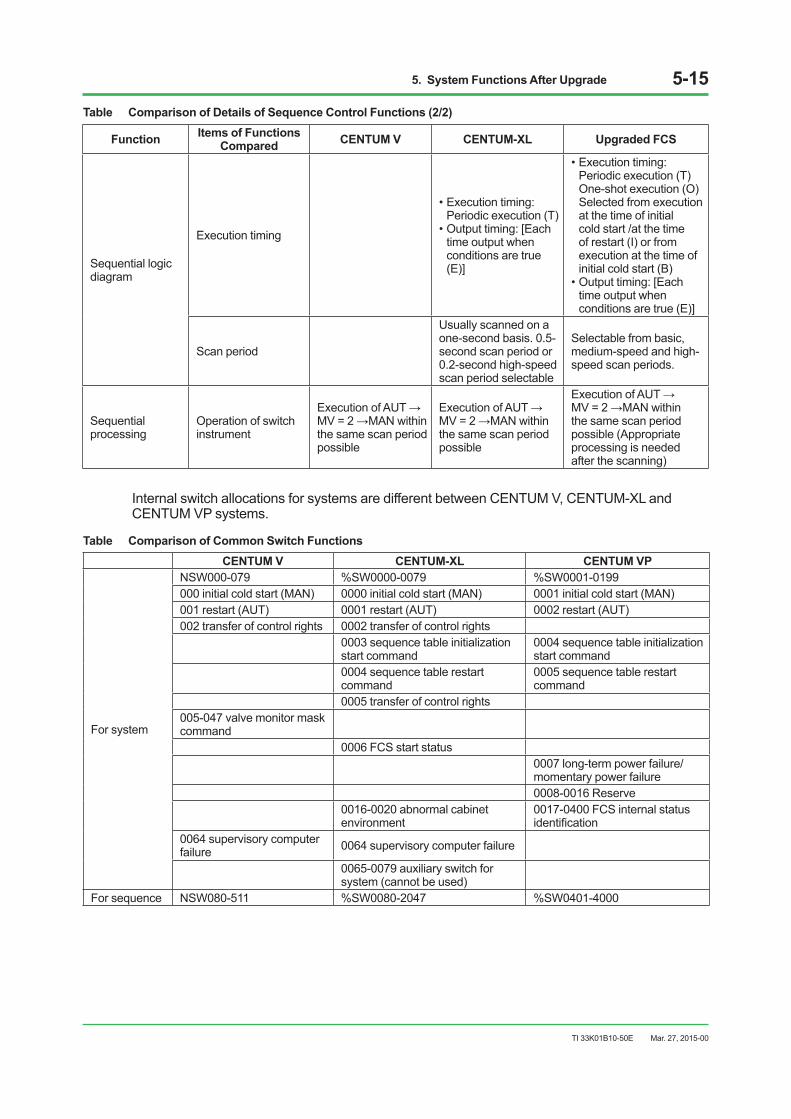
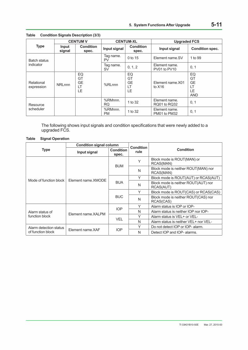
5. System Functions After Upgrade 5-15
TI 33K01B10-50E
Table Comparison of Details of Sequence Control Functions (2/2)
Function Items of Functions Compared CENTUM V CENTUM-XL Upgraded FCS
Sequential logic diagram
Execution timing
•Executiontiming:Periodic execution (T)
•Outputtiming:[Eachtime output when conditions are true (E)]
•Executiontiming:Periodic execution (T) One-shot execution (O) Selected from execution at the time of initial cold start /at the time of restart (I) or from execution at the time of initial cold start (B)
•Outputtiming:[Eachtime output when conditions are true (E)]
Scan period
Usually scanned on a one-second basis. 0.5-second scan period or 0.2-second high-speed scan period selectable
Selectable from basic, medium-speed and high-speed scan periods.
Sequential processing
Operation of switch instrument
ExecutionofAUT→MV=2→MANwithinthe same scan period possible
ExecutionofAUT→MV=2→MANwithinthe same scan period possible
ExecutionofAUT→MV=2→MANwithinthe same scan period possible (Appropriate processing is needed after the scanning)
Internal switch allocations for systems are different between CENTUM V, CENTUM-XL and CENTUM VP systems.
Table Comparison of Common Switch FunctionsCENTUM V CENTUM-XL CENTUM VP
For system
NSW000-079 %SW0000-0079 %SW0001-0199 000 initial cold start (MAN) 0000 initial cold start (MAN) 0001 initial cold start (MAN) 001 restart (AUT) 0001 restart (AUT) 0002 restart (AUT) 002 transfer of control rights 0002 transfer of control rights
0003 sequence table initialization start command
0004 sequence table initialization start command
0004 sequence table restart command
0005 sequence table restart command
0005 transfer of control rights 005-047 valve monitor mask command
0006 FCS start status 0007 long-term power failure/momentary power failure 0008-0016 Reserve
0016-0020 abnormal cabinet environment
0017-0400 FCS internal status identification
0064 supervisory computer failure 0064 supervisory computer failure
0065-0079 auxiliary switch for system (cannot be used)
For sequence NSW080-511 %SW0080-2047 %SW0401-4000
Mar. 27, 2015-00
5. System Functions After Upgrade 5-16
TI 33K01B10-50E
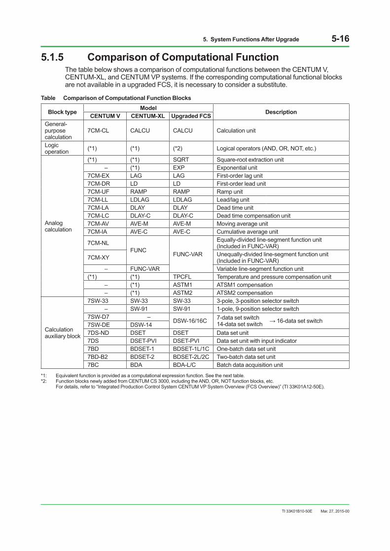
5.1.5 Comparison of Computational FunctionThe table below shows a comparison of computational functions between the CENTUM V, CENTUM-XL, and CENTUM VP systems. If the corresponding computational functional blocks are not available in a upgraded FCS, it is necessary to consider a substitute.
Table Comparison of Computational Function Blocks
Block type Model DescriptionCENTUM V CENTUM-XL Upgraded FCS General-purpose calculation
7CM-CL CALCU CALCU Calculation unit
Logic operation (*1) (*1) (*2) Logical operators (AND, OR, NOT, etc.)
Analog calculation
(*1) (*1) SQRT Square-root extraction unit – (*1) EXP Exponential unit
7CM-EX LAG LAG First-order lag unit 7CM-DR LD LD First-order lead unit 7CM-UF RAMP RAMP Ramp unit 7CM-LL LDLAG LDLAG Lead/lag unit 7CM-LA DLAY DLAY Dead time unit 7CM-LC DLAY-C DLAY-C Dead time compensation unit 7CM-AV AVE-M AVE-M Moving average unit 7CM-IA AVE-C AVE-C Cumulative average unit
7CM-NL FUNC
FUNC-VAR
Equally-divided line-segment function unit (Included in FUNC-VAR)
7CM-XY Unequally-divided line-segment function unit (Included in FUNC-VAR)
– FUNC-VAR Variable line-segment function unit (*1) (*1) TPCFL Temperature and pressure compensation unit
– (*1) ASTM1 ATSM1 compensation – (*1) ASTM2 ATSM2 compensation
Calculation auxiliary block
7SW-33 SW-33 SW-33 3-pole, 3-position selector switch – SW-91 SW-91 1-pole, 9-position selector switch
7SW-D7 –DSW-16/16C 7-data set switch
14-data set switch →16-datasetswitch7SW-DE DSW-14 7DS-ND DSET DSET Data set unit 7DS DSET-PVI DSET-PVI Data set unit with input indicator 7BD BDSET-1 BDSET-1L/1C One-batch data set unit 7BD-B2 BDSET-2 BDSET-2L/2C Two-batch data set unit 7BC BDA BDA-L/C Batch data acquisition unit
*1: Equivalent function is provided as a computational expression function. See the next table.*2: Function blocks newly added from CENTUM CS 3000, including the AND, OR, NOT function blocks, etc.
For details, refer to “Integrated Production Control System CENTUM VP System Overview (FCS Overview)” (TI 33K01A12-50E).
Mar. 27, 2015-00
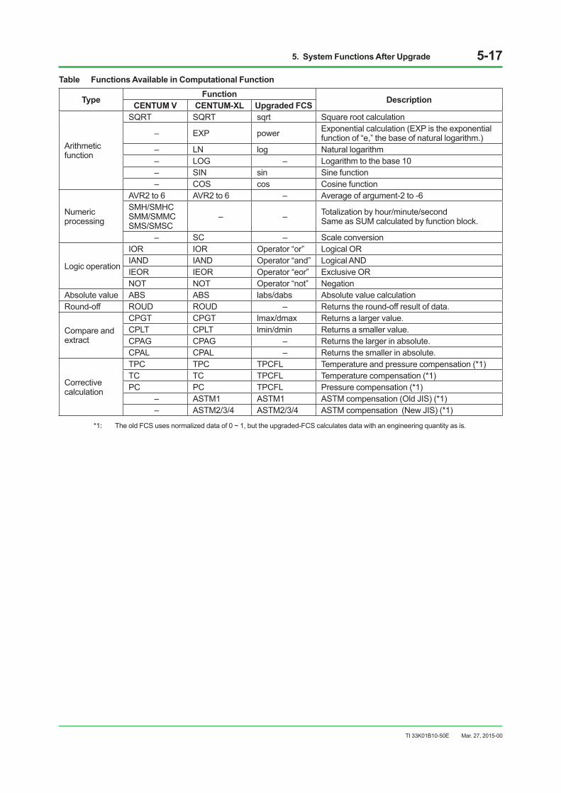
5. System Functions After Upgrade 5-17
TI 33K01B10-50E
Table Functions Available in Computational Function
Type Function DescriptionCENTUM V CENTUM-XL Upgraded FCS
Arithmetic function
SQRT SQRT sqrt Square root calculation
– EXP power Exponential calculation (EXP is the exponential function of “e,” the base of natural logarithm.)
– LN log Natural logarithm – LOG – Logarithm to the base 10 – SIN sin Sine function – COS cos Cosine function
Numeric processing
AVR2 to 6 AVR2 to 6 – Average of argument-2 to -6 SMH/SMHC SMM/SMMC SMS/SMSC
– – Totalization by hour/minute/second Same as SUM calculated by function block.
– SC – Scale conversion
Logic operation
IOR IOR Operator “or” Logical OR IAND IAND Operator “and” Logical AND IEOR IEOR Operator “eor” Exclusive OR NOT NOT Operator “not” Negation
Absolute value ABS ABS labs/dabs Absolute value calculation Round-off ROUD ROUD – Returns the round-off result of data.
Compare and extract
CPGT CPGT lmax/dmax Returns a larger value. CPLT CPLT lmin/dmin Returns a smaller value. CPAG CPAG – Returns the larger in absolute. CPAL CPAL – Returns the smaller in absolute.
Corrective calculation
TPC TPC TPCFL Temperature and pressure compensation (*1)TC TC TPCFL Temperature compensation (*1)PC PC TPCFL Pressure compensation (*1)
– ASTM1 ASTM1 ASTM compensation (Old JIS) (*1)– ASTM2/3/4 ASTM2/3/4 ASTM compensation (New JIS) (*1)
*1: The old FCS uses normalized data of 0 ~ 1, but the upgraded-FCS calculates data with an engineering quantity as is.
Mar. 27, 2015-00
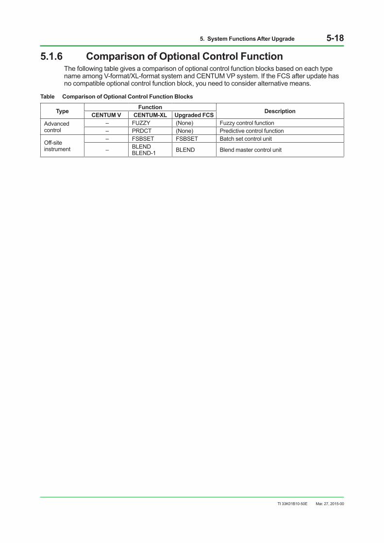
5. System Functions After Upgrade 5-18
TI 33K01B10-50E
5.1.6 Comparison of Optional Control FunctionThe following table gives a comparison of optional control function blocks based on each type name among V-format/XL-format system and CENTUM VP system. If the FCS after update has no compatible optional control function block, you need to consider alternative means.
Table Comparison of Optional Control Function Blocks
Type Function DescriptionCENTUM V CENTUM-XL Upgraded FCS Advanced control
– FUZZY (None) Fuzzy control function– PRDCT (None) Predictive control function
Off-site instrument
– FSBSET FSBSET Batch set control unit
– BLENDBLEND-1 BLEND Blend master control unit
Mar. 27, 2015-00

5. System Functions After Upgrade 5-19
TI 33K01B10-50E
5.2 UpgradeSpecificationsYokogawa performs upgrade work based on the following standards.
Node numberI/O nests in the old FCS are replaced with node units in the upgraded-FCS. In this case, “A new nodenumber=anoldnestnumber+1”shallbeconfiguredasshowninthefigurebelow.Thisis a measure to be taken to make slot positions of an I/O card (module) equal before and after upgrading the FCS. The I/O slots of the FCU after upgrade are equipped with communication modules (*1) for node unit.*1: Those are EC401, EC402, ANT401, ANT411, etc.
F050201E.ai
New FCS after upgradeOld FCS before upgrade
SCN
Nest 1
Nest 2
Nest 4
Nest 3
Nest 5
FCU(Node 1)
Node 2
Node 3
Node 4
Node 5
Node 6
Figure Comparison between Old Nest Number and New Node Number
Tag name1. Regulatory control function block A maximum of eight character tag numbers for CENTUM V and CENTUM-XL are directly
convertedtoamaximumof16charactertagnumbersforCENTUMVPfieldcontrolstations. In addition, tag names in the case where there is an additional block including corrective
calculation, add branch numbers to original tag numbers. Additional tag name rules: <Original tag name> + <X> + <1 to 3> Example: Original tag number P100, additional tag number P100X1
Mar. 27, 2015-00
5. System Functions After Upgrade 5-20
TI 33K01B10-50E
2. Sequence element A sequence element is converted into a tag name with a station number identifying the
station. Example: xxxxxxSddss (dd: domain, ss: station)
Tag commentA maximum of eight-character tag comments for CENTUM V and a maximum of 16 single-byte character tag comments for CENTUM-XL are directly converted to tag comments (a maximum of 24characters)forCENTUMVPfieldcontrolstations.Inaddition,ifCENTUMVusessingle-byteKatakana characters, they are converted to double-byte Katakana characters.
Element numberElement numbers start with 0 for CENTUM V and with 1 for CENTUM VP systems. An element in number0(zero)ismovedtonumber100bydefinition.
Computational expressionEach corresponding tag is registered on the control drawing as a functional block. Computational expressions are converted manually because they cannot be simply converted in such a way that their data format is changed from the normalized data to engineering unit data. However, the following conversions are made to existing computational expressions and left as comments. Note that R4.01.60 or later supports normalization so the normalized data can be converted.
• Processdatarangesusedincomputationalexpressionsaredescribedascomments.(Nobuffer ranges are described)
• Ifatagnameincludes“-”orstartswithanumericcharacter,specifyanaliastouseatag name + item name (a maximum of eight characters) or AL01 ... in a serial number (a minimum of eight characters) as aliases.
Station data link• ConversionofCENTUMV,7SL-DT
7SL-DT converts the transmission buffer and the receive buffer to BDA-L and BDSET-1L respectively and also converts inter-station communications to CALCU. Ifthebufferinthe7SL-DTisdirectlyreferencedandsetbyanintra-listrelativespecification,or the same data in the buffer are set and referenced in multiple sections, a manual conversion is made.
• ConversionofCENTUM-XL,SDL SDL converts the transmission buffer and the receive buffer to BDA-L and BDSET-1L respectively and also converts inter-station communications to CALC to execute BDA-L, CALCU, and BDSET-1L in order.
Mar. 27, 2015-00

5. System Functions After Upgrade 5-21
TI 33K01B10-50E
5.3 Application Capacity of Upgraded FCSWhen upgrading CENTUM V or CENTUM-XL to CENTUM VP, use a FFCS-V. The table shows the application capacities of the CENTUM V, CENTUM-XL and CENTUM VP systems.
Table Comparison of Application CapacitiesCENTUM V CENTUM-XL CENTUM VP
Function CFCS2 /CFCD2
CFSS /CFSD Function EFCS
/D-S1 EFCS /D-H2 Function
General type Batch typeLFS1700 LFS1750
(10 nodes)LFS1750(14 nodes) LFS1700 LFS1750
(10 nodes)LFS1750(14 nodes)
Internal instrument(DDC calc.)
255 255 Internal instrument(DDC calc.)
255 255 Regulatory control, calculation
500 1200 1800 400 1000 1500
– – – – – – Batch data 100 400 600 50 100 150
Arithmetic expression 255 255 Arithmetic
expression 255 255 General-purpose calculation
400 500 750 120 250 350
Sequence table
40 (99)
200 (255)
Sequence table 200 200
Sequence table (S)Sequence table (M)Sequence table (L)
200
100
100
400
200
200
700
400
300
100
50
50
200
100
100
400
150
150Timer/counter/ code I/O
200 99
512 200
Timer/counter/ code I/O
511 511 Sequence auxiliary -1 500 700 1100 500 700 1100
Relational expression Valve monitor
99 128
200 128
Relational expression Valve monitor
255 255
255 255
Sequence auxiliary -2 100 200 300 50 100 150
– – – Switch instrument 255 511 Switch
instrument 500 1000 1500 500 1000 1500
– – –Batch status indicator
32 32 Faceplate 120 200 300 50 100 150
– – – – – – SFC block 40 100 300 100 200 300Sequence message 255 255 Sequence
message 255 255 Printout message 2000 2000 2000 2000 2000 2000
– – –Message with data attached
100 100 – – – – – – –
Message request 100 100 Message
request 100 100 Message request 200 200 200 200 200 200
Operator guide message
100 100 Operator guide message
100 100 Operator guide message
1000 1000 1000 1000 1000 1000
– – –Request for voice output
100 100 – – – – – – –
FORTRAN program initiation
100 100 – – –Supervisory computer message for PICOT
9999 9999 9999 9999 9999 9999
High-order interrupt request
100 100 High-order interrupt request
510 510 Supervisory computer event message
9999 9999 9999 9999 9999 9999
Annunciator 255 255 Annunciator 255 255 Annunciator 2000 2000 2000 2000 2000 2000Common switch 512 512 Common
switch 2048 2048 Common switch 9000 9000 9000 9000 9000 9000
Contact input
512 512 Contact input
768 768 Contact input
1920 4096 4096 1920 4096 4096Contact output
Contact output
Contact output
- - -Instrument/ loop drawing
24 24 Block/1 drawing 100 100 100 100 100 100
- - - Loop drawing 200 200 Drawing 200 200(300/400/500) 200 200(300/400/500)
Mar. 27, 2015-00
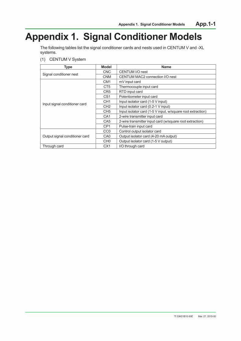
Appendix 1. Signal Conditioner Models App.1-1
TI 33K01B10-50E
Appendix 1. Signal Conditioner ModelsThe following tables list the signal conditioner cards and nests used in CENTUM V and -XL systems. (1) CENTUM V System
Type Model Name
Signal conditioner nest CNC CENTUM I/O nest CNM CENTUM MAC2 connection I/O nest
Input signal conditioner card
CM1 mV input card CT5 Thermocouple input card CR5 RTD input card CS1 Potentiometer input card CH1 Input isolator card (1-5 V input) CH2 Input isolator card (0.2-1 V input) CH5 Input isolator card (1-5 V input, w/square root extraction) CA1 2-wire transmitter input card CA5 2-wire transmitter input card (w/square root extraction) CP1 Pulse-train input card
Output signal conditioner card CC0 Control output isolator card CA0 Output isolator card (4-20 mA output) CH0 Output isolator card (1-5 V output)
Through card CX1 I/O through card
Mar. 27, 2015-00

Appendix 1. Signal Conditioner Models App.1-2
TI 33K01B10-50E
(2) CENTUM-XL System
Type Model Name
Signal conditioner nest
ENC I/O signal conditioner nest ENM Control I/O signal conditioner nest MHC I/O signal conditioner nest MHM Control I/O signal conditioner nest
Signal conditioner power supply PS40 Power unit (24 V DC) PS41 Power unit (220/230/240 V AC)
Input signal conditioner card
ET5 Thermocouple input card ER5 RTD input card ES1 Potentiometer input card EM1 mV input card EH1 Input isolator card (1-5 V input) EH5 Input isolator card (1-5 V input, w/square root extraction) EA1 2-wire transmitter input card EA2 2-wire transmitter input card (w/communication function) EA5 2-wire transmitter input card (1-5 V, w/square root extraction) EP1 Pulse-train input card EP3 Frequency input card EA9 I/O Non-isolated distributor
Output signal conditioner card EC0 Control output isolator card EA0 Output isolator card (4-20 mA output) EH0 Output isolator card (1-5 V output)
Common card ESC Signal conditioner communication card EXT Extension card EX1 I/O through card
Mar. 27, 2015-00
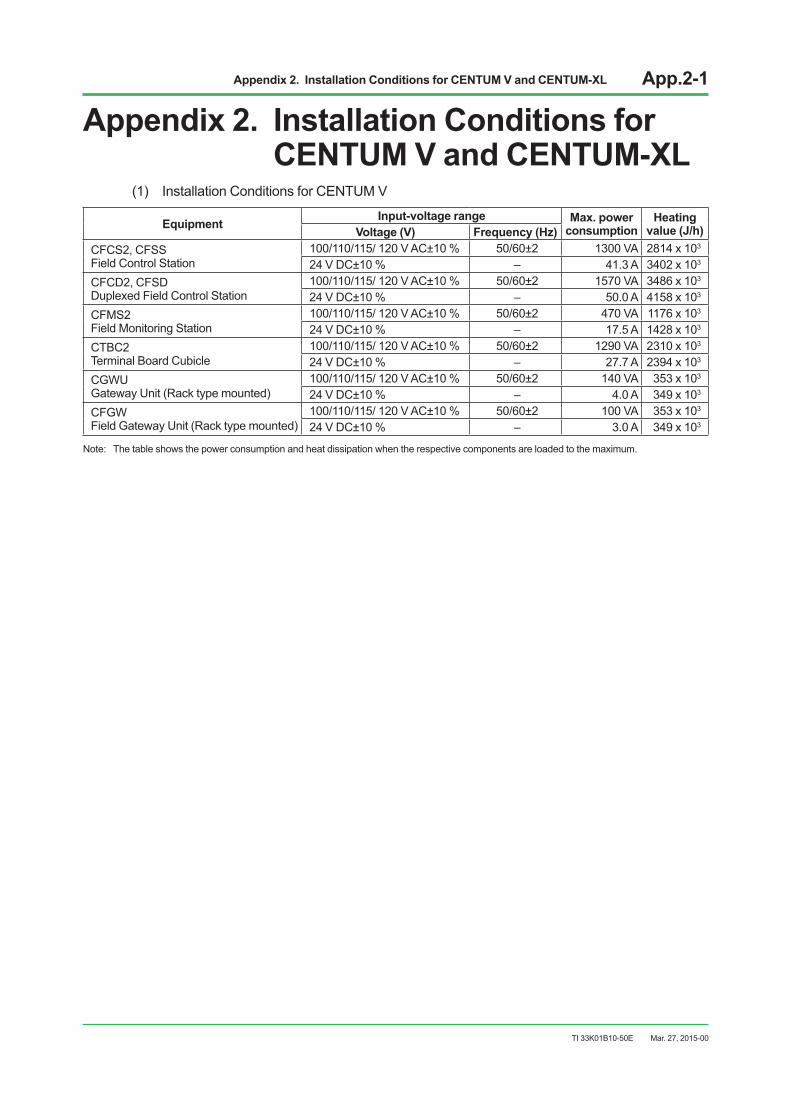
Appendix 2. Installation Conditions for CENTUM V and CENTUM-XL App.2-1
TI 33K01B10-50E
Appendix 2. Installation Conditions for CENTUM V and CENTUM-XL
(1) Installation Conditions for CENTUM V
Equipment Input-voltage range Max. power consumption
Heating value (J/h)Voltage (V) Frequency (Hz)
CFCS2, CFSS Field Control Station
100/110/115/ 120 V AC±10 % 50/60±2 1300 VA 2814 x 103 24 V DC±10 % – 41.3 A 3402 x 103
CFCD2, CFSD Duplexed Field Control Station
100/110/115/ 120 V AC±10 % 50/60±2 1570 VA 3486 x 103
24 V DC±10 % – 50.0 A 4158 x 103 CFMS2 Field Monitoring Station
100/110/115/ 120 V AC±10 % 50/60±2 470 VA 1176 x 103
24 V DC±10 % – 17.5 A 1428 x 103 CTBC2 Terminal Board Cubicle
100/110/115/ 120 V AC±10 % 50/60±2 1290 VA 2310 x 103 24 V DC±10 % – 27.7 A 2394 x 103
CGWU Gateway Unit (Rack type mounted)
100/110/115/ 120 V AC±10 % 50/60±2 140 VA 353 x 103 24 V DC±10 % – 4.0 A 349 x 103
CFGW Field Gateway Unit (Rack type mounted)
100/110/115/ 120 V AC±10 % 50/60±2 100 VA 353 x 103 24 V DC±10 % – 3.0 A 349 x 103
Note: The table shows the power consumption and heat dissipation when the respective components are loaded to the maximum.
Mar. 27, 2015-00

Appendix 2. Installation Conditions for CENTUM V and CENTUM-XL App.2-2
TI 33K01B10-50E
(2) Installation Conditions for CENTUM-XL
Equipment Input-voltage range Max. power consumption
Heating value (J/h)Voltage (V) Frequency (Hz)
EFCS-S Field Control Station
90 to 125 V AC 50/60
1780 VA 3800 x 103 198 to 254.4 V AC 2100 VA 4100 x 103 24 V DC – 47 A 3900 x 103
EFCD Duplexed Field Control Station
90 to 125 V AC 50/60
1950 VA 4200 x 103 198 to 254.4 V AC 2400 VA 4500 x 103 24 V DC – 53 A 4400 x 103
EFUS Field Control Unit
90 to 125 V AC 50/60
250 VA 460 x 103 198 to 254.4 V AC 250 VA 460 x 103 24 V DC – 5 A 420 x 103
EFUD Field Control Unit
90 to 125 V AC 50/60
280 VA 500 x 103 198 to 254.4 V AC 280 VA 500 x 103 24 V DC – 5.5 A 460 x 103
EFMS Field Monitoring Station
90 to 125 V AC 50/60
910 VA 1900 x 103 198 to 254.4 V AC 1050 VA 1900 x 103 24 V DC – 16 A 1300 x 103
ETBC Terminal Board Cabinet
90 to 125 V AC 50/60
1760 VA 3800 x 103 198 to 254.4 V AC 2250 VA 4000 x 103 24 V DC – 48 A 4000 x 103
EFGW Field Gateway Unit
90 to 125 V AC 50/60
170 VA 250 x 103 198 to 254.4 V AC 180 VA 250 x 103 24 V DC V AC – 3 A
Note: The table shows the power consumption and heat dissipation when the respective components are loaded to the maximum.
Mar. 27, 2015-00

Appendix 3. Tuning Parameter Differences App.3-1
TI 33K01B10-50E
Appendix 3. Tuning Parameter Differences
It may be necessary to reset the tuning parameters between the existing CENTUM V or CENTUM-XL and CENTUM VP system. The following pages show the data types of the tuning parameters that are different in the CENTUM V, CENTUM-XL and CENTUM VP systems. In addition, tuning parameters marked with a number in the conversion equation column require conversion. See the table “Equations for Tuning Parameters Requiring Conversion” at the end of this chapter.
CENTUM V and CENTUM VP
Table Tuning Parameters Difference between CENTUM V and CENTUM VP(1/5)
CENTUM V Instrument type
CENTUM VP Function block
CENTUM V Data type
CENTUM VP Data item
Conversion equation
Common – ALRM, AS, ASUB ALRM (*25)Common – LOOP, LS, LSUB MODE, BSTS (*26)Common – SM(EOPS indicates as SUM) SUMCommon(7DC-*) – K1 Control direction: DRCommon – K2(EOPS indicates as SU) (None)Common – K3(EOPS indicates as SM) (None)Common – K5 RAWCommon – AV (None)Common – SD (None)Common – RD (None)Common(7CM-*) – PV CPVCommon(7CM-*) – K4 GAINCommon – MH, ML, MV Ditto as left (*1)Common(7DC-*) – P, I, D Ditto as left (*20)7PV PVI No difference except "Common"7PV-DV PVI-DV No difference except "Common"7DC-D5/N5 PID BS GW (*3)
CS CK7DC-D6/N6 PID BS GW (*3)
CS CK7DC-B5 PID-BSW BS BIAS (*4)
CS LK (*3)7DC-D3 PD-MR BS MR (*1)
CS CKK7 CALC (*1)
7DC-C2 ONOFF CS CK7DC-C3 ONOFF-G BS DB (*3)
CS CK7DC-C9 PID-TP BS GW (*3)
Mar. 27, 2015-00

Appendix 3. Tuning Parameter Differences App.3-2
TI 33K01B10-50E
CENTUM V Instrument type
CENTUM VP Function block
CENTUM V Data type
CENTUM VP Data item
Conversion equation
7DC-D9 PI-BLEND VL VL (*2)D TKBS RP (*4)DL DL (*2)K4 RST (*5)
7ML-ND MLD No difference except "Common"7ML MLD-PVI No difference except "Common"7ML-SW MLD-SW BS BIAS (*7)
CS GAINSH SSHSL SSL
7ML-XN MLD-SW BS BIAS (*7)CS GAINDL RP (*6)SH SSHSL SSL
7RL VELLIM K1 DMVP (*8)K2 DMVM (*8)K3 TU (*9)K4 BPSW
7RS RATIO BS + CS BIAS (*10)K7 CALC (*1)DL RPRS SSH
7SS-A AS-H/M/L SV SWPH SWHPL SWL
7SS-S SS-H/M/L SV SWPH SWHPL SWL
7RD SS-DUAL K4 SWK6 RV1K7 RV2
7SW-33 SW-33 SV SWPH SWHPL SWL
7SW-D7/DE DSW-16 PV CPVSV SWD1 to D9, DA to DE
SD01 to SD09, SD10 to SD14
7DS-ND DSET PH SVHPL SVL
Mar. 27, 2015-00
Table Tuning Parameters Difference between CENTUM V and CENTUM VP(2/5)
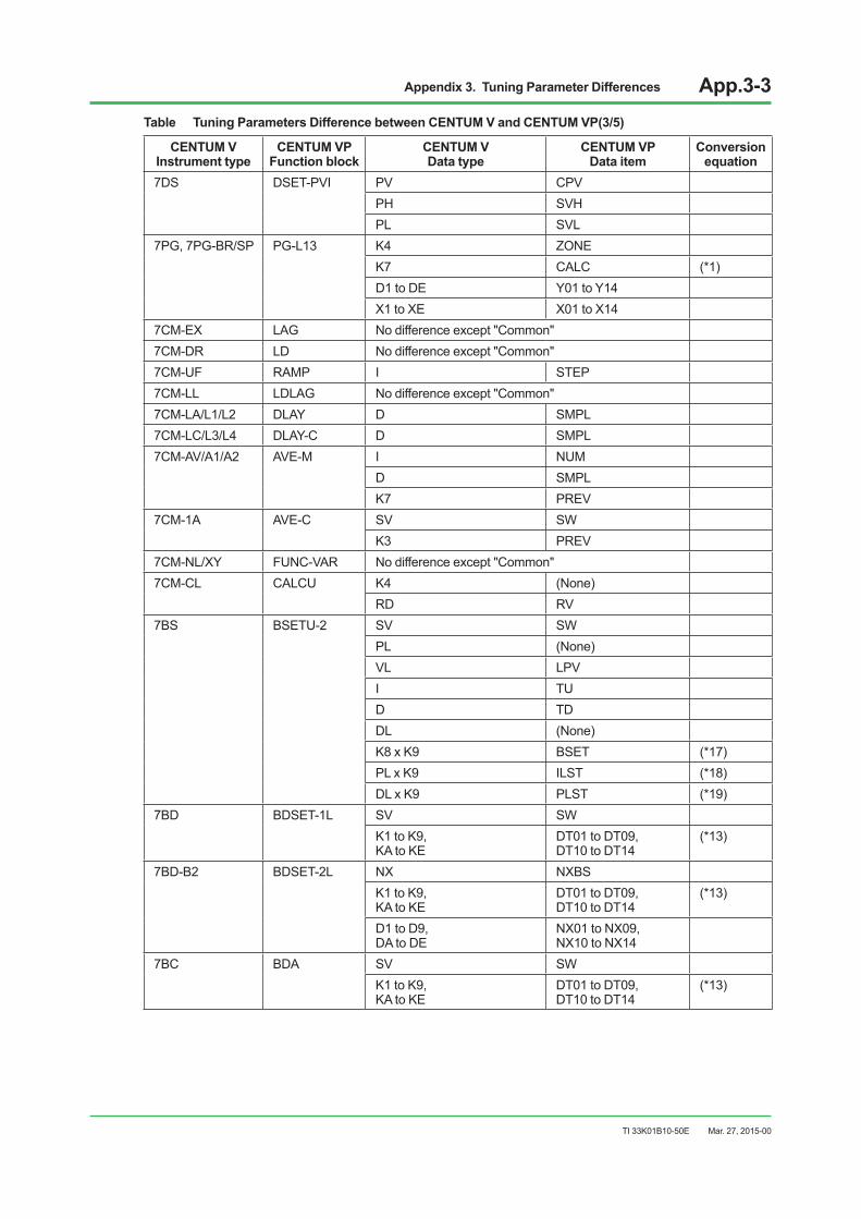
Appendix 3. Tuning Parameter Differences App.3-3
TI 33K01B10-50E
CENTUM V Instrument type
CENTUM VP Function block
CENTUM V Data type
CENTUM VP Data item
Conversion equation
7DS DSET-PVI PV CPVPH SVHPL SVL
7PG, 7PG-BR/SP PG-L13 K4 ZONEK7 CALC (*1)D1 to DE Y01 to Y14X1 to XE X01 to X14
7CM-EX LAG No difference except "Common"7CM-DR LD No difference except "Common"7CM-UF RAMP I STEP7CM-LL LDLAG No difference except "Common"7CM-LA/L1/L2 DLAY D SMPL7CM-LC/L3/L4 DLAY-C D SMPL7CM-AV/A1/A2 AVE-M I NUM
D SMPLK7 PREV
7CM-1A AVE-C SV SWK3 PREV
7CM-NL/XY FUNC-VAR No difference except "Common"7CM-CL CALCU K4 (None)
RD RV7BS BSETU-2 SV SW
PL (None)VL LPVI TUD TDDL (None)K8 x K9 BSET (*17)PL x K9 ILST (*18)DL x K9 PLST (*19)
7BD BDSET-1L SV SWK1 to K9, KA to KE
DT01 to DT09, DT10 to DT14
(*13)
7BD-B2 BDSET-2L NX NXBSK1 to K9, KA to KE
DT01 to DT09, DT10 to DT14
(*13)
D1 to D9, DA to DE
NX01 to NX09, NX10 to NX14
7BC BDA SV SWK1 to K9, KA to KE
DT01 to DT09, DT10 to DT14
(*13)
Mar. 27, 2015-00
Table Tuning Parameters Difference between CENTUM V and CENTUM VP(3/5)

Appendix 3. Tuning Parameter Differences App.3-4
TI 33K01B10-50E
CENTUM V Instrument type
CENTUM VP Function block
CENTUM V Data type
CENTUM VP Data item
Conversion equation
7MC-C2/C3 MC-2/3 PV FV
MV MV (*15)
PL ANSP
MH (None)
ML (None)
I MTM
K4 CSV
K5 RAW
K7 BPSW
7UN ADL No difference except "Common"
7SL-DT ADL No difference except "Common"
7SL-SD/RV BDA-L SV SW
BDSET-1L K1 to K9, KA to KE
DT01 to DT09, DT10 to DT14
(*13)
(YS80) SLCD No difference except "Common"
(YS80) SLPC X1 to X3 AUX1 to AUX3
(YS80) SLMC X1 to X3 AUX1 to AUX3
(YS80) SMST111 No difference except "Common"
(YS80) SMST121 No difference except "Common"
(YS80) SMRT K7 (None)
RS SSH
P1 to P4 P01 to P04
D1 to D4 CC1 to CC4
(YS80) SBSD BT BSET
K8 to K9 (None)
D1 to D4 CC1 to CC4
(YS80) SLBC BT BSET
K8 to K9 (None)
D1 to D4 CC1 to CC4
(YS80) SLCC RS SSH
D1 to D4 CC1 to CC4
(YS80) STLD D1 to D4 CC1 to CC4
NST ST16 K1 MODE (*21)
NSW %SW No difference except "Common" (*22)
NAN %AN No difference except "Common"
NDI %Z No difference except "Common"
NDO %Z No difference except "Common"
NTM TM ALRM BSTS
NCT CTS ALRM BSTS
NCT CTP ALRM BSTS
Mar. 27, 2015-00
Table Tuning Parameters Difference between CENTUM V and CENTUM VP(4/5)
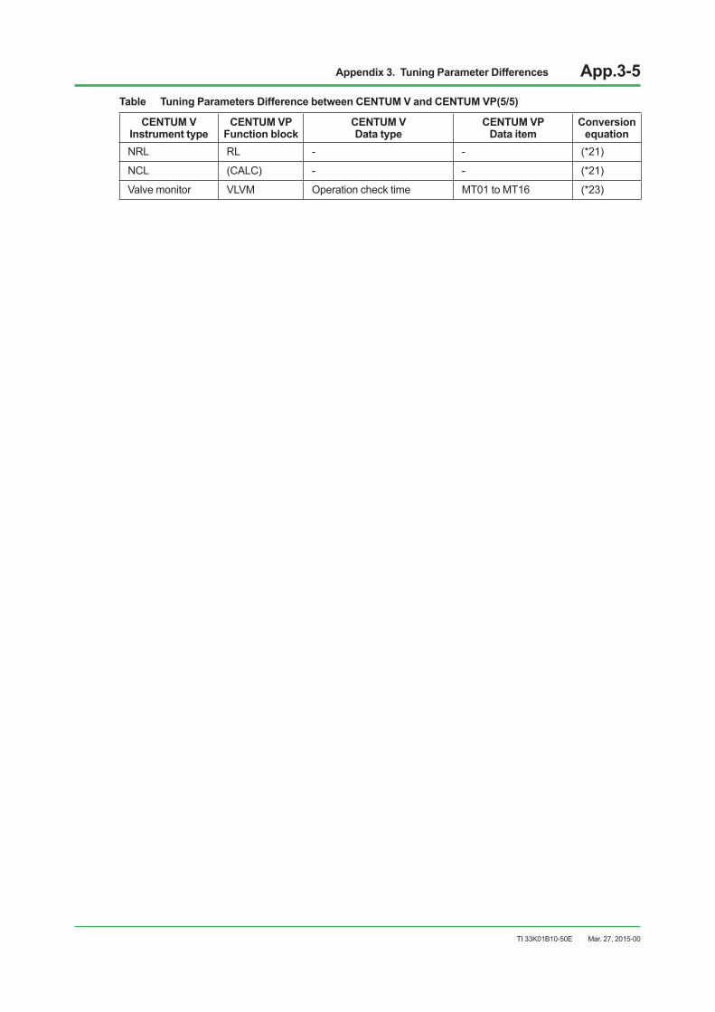
Appendix 3. Tuning Parameter Differences App.3-5
TI 33K01B10-50E
CENTUM V Instrument type
CENTUM VP Function block
CENTUM V Data type
CENTUM VP Data item
Conversion equation
NRL RL - - (*21)
NCL (CALC) - - (*21)
Valve monitor VLVM Operation check time MT01 to MT16 (*23)
Mar. 27, 2015-00
Table Tuning Parameters Difference between CENTUM V and CENTUM VP(5/5)
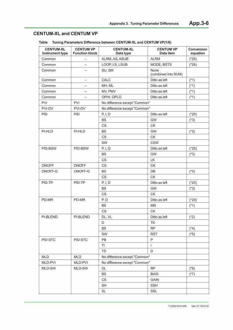
Appendix 3. Tuning Parameter Differences App.3-6
TI 33K01B10-50E
CENTUM-XL and CENTUM VP
Table Tuning Parameters Difference between CENTUM-XL and CENTUM VP(1/6)
CENTUM-XL Instrument type
CENTUM VP Function block
CENTUM-XL Data type
CENTUM VP Data item
Conversion equation
Common – ALRM, AS, ASUB ALRM (*25)Common – LOOP, LS, LSUB MODE, BSTS (*26)Common – SU, SM None
(combined into SUM)Common – CALC Ditto as left (*1)Common – MH, ML Ditto as left (*1)Common – MV, PMV Ditto as left (*1)Common – OPHI, OPLO Ditto as left (*1)PVI PVI No difference except "Common"PVI-DV PVI-DV No difference except "Common"PID PID P, I, D Ditto as left (*20)
BS GW (*3)CS CK
PI-HLD PI-HLD BS GW (*3)CS CKSW CSW
PID-BSW PID-BSW P, I, D Ditto as left (*20)BS GW (*3)CS LK
ONOFF ONOFF CS CKONOFF-G ONOFF-G BS DB (*3)
CS CKPID-TP PID-TP P, I, D Ditto as left (*20)
BS GW (*3)CS CK
PD-MR PD-MR P, D Ditto as left (*20)BS MR (*1)CS CK
PI-BLEND PI-BLEND DL, VL Ditto as left (*2)D TKBS RP (*4)SW RST (*5)
PID-STC PID-STC PB PTI ITD D
MLD MLD No difference except "Common"MLD-PVI MLD-PVI No difference except "Common"MLD-SW MLD-SW DL RP (*6)
BS BIAS (*7)CS GAINSH SSHSL SSL
Mar. 27, 2015-00

Appendix 3. Tuning Parameter Differences App.3-7
TI 33K01B10-50E
CENTUM-XL Instrument type
CENTUM VP Function block
CENTUM-XL Data type
CENTUM VP Data item
Conversion equation
VELLIM VELLIM DMVP, DMVM Ditto as left (*8)TU TU (*9)SW BPSW (*9)SH SSHSL SSL
RATIO RATIO CALC CALC (*1)DL RPBS + CS BIAS (*10)RS SSH
AS-H/M/L AS-H/M/L PH SWHPL SWLSV SW
SS-H/M/L SS-H/M/L PH SWHPL SWLSV SW
SS-DUAL SS-DUAL PV1, PV2 RV1, RV2SW-33 SW-33 SV SW
PH SWHPL SWL
SW-91 SW-91 SV SWPH SWHPL SWL
DSW-14 DSW-16 PV CPVSV SW
DSET DSET PH SVHPL SVL
DSET-PVI DSET-PVI No difference except "Common"PG-L13/S13 PG-L13 RS SH - SL
Y01 to Y14 Ditto as left (*1)BSZ ZSTRBEZ ZEND
LAG LAG PV CPVLD LD PV CPVRAMP RAMP I STEPLDLAG LDLAG PV CPVDLAY DLAY PV CPV
D SMPLSW RST (*5)
DLAY-C DLAY-C PV CPVD SMPLSW RST
Mar. 27, 2015-00
Table Tuning Parameters Difference between CENTUM-XL and CENTUM VP(2/6)
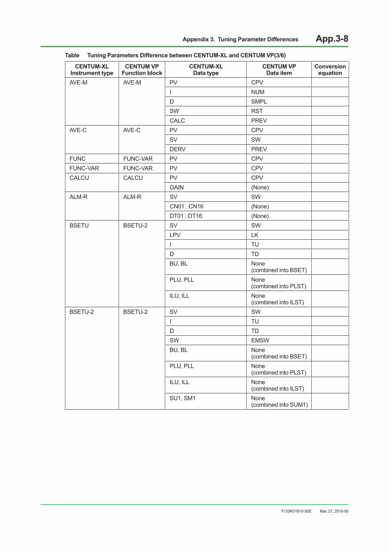
Appendix 3. Tuning Parameter Differences App.3-8
TI 33K01B10-50E
CENTUM-XL Instrument type
CENTUM VP Function block
CENTUM-XL Data type
CENTUM VP Data item
Conversion equation
AVE-M AVE-M PV CPVI NUMD SMPLSW RSTCALC PREV
AVE-C AVE-C PV CPVSV SWDERV PREV
FUNC FUNC-VAR PV CPVFUNC-VAR FUNC-VAR PV CPVCALCU CALCU PV CPV
GAIN (None)ALM-R ALM-R SV SW
CN01~CN16 (None)DT01~DT16 (None)
BSETU BSETU-2 SV SWLPV LKI TUD TDBU, BL None
(combined into BSET)PLU, PLL None
(combined into PLST)ILU, ILL None
(combined into ILST)BSETU-2 BSETU-2 SV SW
I TUD TDSW EMSWBU, BL None
(combined into BSET)PLU, PLL None
(combined into PLST)ILU, ILL None
(combined into ILST)SU1, SM1 None
(combined into SUM1)
Mar. 27, 2015-00
Table Tuning Parameters Difference between CENTUM-XL and CENTUM VP(3/6)
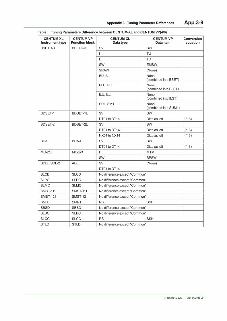
Appendix 3. Tuning Parameter Differences App.3-9
TI 33K01B10-50E
CENTUM-XL Instrument type
CENTUM VP Function block
CENTUM-XL Data type
CENTUM VP Data item
Conversion equation
BSETU-3 BSETU-3 SV SWI TUD TDSW EMSWSRAW (None)BU, BL None
(combined into BSET)PLU, PLL None
(combined into PLST)ILU, ILL None
(combined into ILST)SU1, SM1 None
(combined into SUM1)BDSET-1 BDSET-1L SV SW
DT01 to DT14 Ditto as left (*13)BDSET-2 BDSET-2L SV SW
DT01 to DT14 Ditto as left (*13)NX01 to NX14 Ditto as left (*13)
BDA BDA-L SV SWDT01 to DT14 Ditto as left (*13)
MC-2/3 MC-2/3 I MTMSW BPSW
SDL~SDL-2 ADL SV (None)DT01 to DT14
SLCD SLCD No difference except "Common"SLPC SLPC No difference except "Common"SLMC SLMC No difference except "Common"SMST-111 SMST-111 No difference except "Common"SMST-121 SMST-121 No difference except "Common"SMRT SMRT RS SSHSBSD SBSD No difference except "Common"SLBC SLBC No difference except "Common"SLCC SLCC RS SSHSTLD STLD No difference except "Common"
Mar. 27, 2015-00
Table Tuning Parameters Difference between CENTUM-XL and CENTUM VP(4/6)
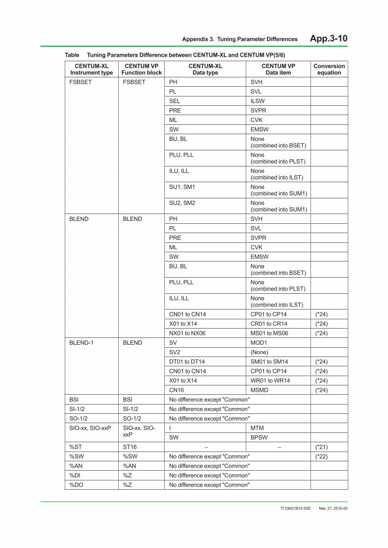
Appendix 3. Tuning Parameter Differences App.3-10
TI 33K01B10-50E
CENTUM-XL Instrument type
CENTUM VP Function block
CENTUM-XL Data type
CENTUM VP Data item
Conversion equation
FSBSET FSBSET PH SVHPL SVLSEL ILSWPRE SVPRML CVKSW EMSWBU, BL None
(combined into BSET)PLU, PLL None
(combined into PLST)ILU, ILL None
(combined into ILST)SU1, SM1 None
(combined into SUM1)SU2, SM2 None
(combined into SUM1)BLEND BLEND PH SVH
PL SVLPRE SVPRML CVKSW EMSWBU, BL None
(combined into BSET)PLU, PLL None
(combined into PLST)ILU, ILL None
(combined into ILST)CN01 to CN14 CP01 to CP14 (*24)X01 to X14 CR01 to CR14 (*24)NX01 to NX06 MS01 to MS06 (*24)
BLEND-1 BLEND SV MOD1SV2 (None)DT01 to DT14 SM01 to SM14 (*24)CN01 to CN14 CP01 to CP14 (*24)X01 to X14 WR01 to WR14 (*24)CN16 MSMD (*24)
BSI BSI No difference except "Common"SI-1/2 SI-1/2 No difference except "Common"SO-1/2 SO-1/2 No difference except "Common"SIO-xx, SIO-xxP SIO-xx, SIO-
xxPI MTMSW BPSW
%ST ST16 – – (*21)%SW %SW No difference except "Common" (*22)%AN %AN No difference except "Common"%DI %Z No difference except "Common"%DO %Z No difference except "Common"
Mar. 27, 2015-00
Table Tuning Parameters Difference between CENTUM-XL and CENTUM VP(5/6)

Appendix 3. Tuning Parameter Differences App.3-11
TI 33K01B10-50E
CENTUM-XL Instrument type
CENTUM VP Function block
CENTUM-XL Data type
CENTUM VP Data item
Conversion equation
%TM TM ALRM BSTS%CT CTS, CTP ALRM BSTS%CI CI ALRM BSTS%CO CO ALRM BSTS%RL RL – – (*21)%CL (CALC) – – (*21)%RM RS – –Valve monitor VLVM Operation check time MT01 to MT16 (*23)
Mar. 27, 2015-00
Table Tuning Parameters Difference between CENTUM-XL and CENTUM VP(6/6)

Appendix 3. Tuning Parameter Differences App.3-12
TI 33K01B10-50E
Table Equations for Tuning Parameters Requiring Conversion(1/2)
conversion equation Conversion Detail Conversion Equation
(Y: converted; X: prior to conversion) Remarks
(*1) Express MV range in engineering unit Y=(MSH-MSL) * X+MSL (*2) Express DV span in engineering unit Y=(DSH-DSL) * X (*3) Express PV span in engineering unit Y=(SH-SL) * X (*4) Express MV span in engineering unit Y=(MSH-MSL) * X
(*5) Reverse 1 and 0 If(X==0)→Y=1If(X==1)→Y=0
(*6) Express SV range in engineering unit Y=(SSH-SSL) * X+SSL (*7) Express SV span in engineering unit Y=(SSH-SSL) * X
(*8) Rate of change set value on UP/DOWN side Y=(X-SSL)/(SSH-SSL) * (MSH-MSL)
(*9) Number transfer Y=X-1
(*10) Bias calculation BIAS=(BS/100+CS) * (MSH-MSL) -MSL/(MSH-MSL) +SL/(SH-SL) * KP
(*11) Switch position If(X==1or2or3)→Y=XIf(X==4) →Y=3
(*12) Express PV range in engineering unit Y=(SH-SL) * X+SL (*13) Reflectionoflinksourcerange No conversion No conversion (*14) Conversion in input source range Y=X * (connecting range)
(*15) Response to 0, 1, and 2 If(X==0.0) →Y==0If(X==50.0) →Y==1If(X==100.0)→Y==2
(*16) Ratio gain KR=(SH-SL) * SSH/(MSH-MSL)/4 * KP KP=ratio gain (*17) Batch set BSET=K8 * K9 (*18) Batch set ILST=PL * K9 (*19) Batch set PLST=DL * K9
(*20) PID parameterIn case of using D parameter, re-tuning of PID is basically required because the D-term calculation algorithm has been changed.
Refer to "4.5.3 Handling tuning parameters."
(*21) Sequence table, relational expression, operational expression
There are difference in function as an instrument (function block) rather than a category of tuning parameter. (These are automatically converted by the tool.)
Refer to "5.1.4 Comparison of sequence control function."
(*22) Internal switchTake care that the switch number in the system area is different. (This is the target of automatic conversion by the tool.)
Refer to "5.1.4 Comparison of sequence control function."
(*23) Valve output monitoring
This parameter, which has been set in [OperationCheckTime]ofthevalveoutputmonitoring builder in old FCS, is upgraded to MTxx of VLVM in CENTUM VP.
(*24) Off-site instrument (BLEND)
BLEND and BLEND-1 instruments of CENTUM-XL are integrated into the BLEND block of CENTUM VP.At this time, the interface from a supervisory computer is also changed, thus reimplementation of engineering is required.Therefore, parameters with this conversion number only indicates compatibility with XL-to-VP upgrade, and is not actually the target of conversion.
(*25) Alarm status
The basic alarm status still remains as ALRM.CAL that was included in the conventional alarm status is changed to the data status of a process variable (such as &PV).
Refer to "5.1.2 Comparison of function block's common function."
Mar. 27, 2015-00
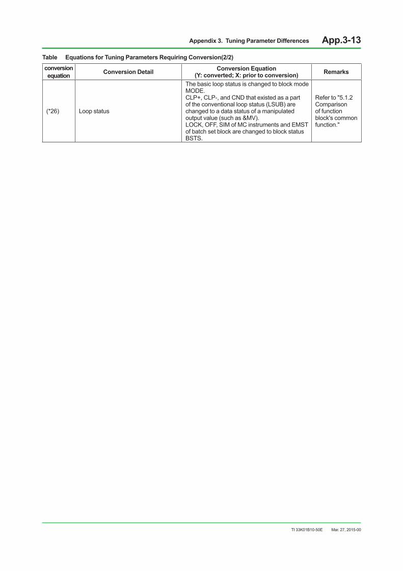
Appendix 3. Tuning Parameter Differences App.3-13
TI 33K01B10-50E
conversion equation Conversion Detail Conversion Equation
(Y: converted; X: prior to conversion) Remarks
(*26) Loop status
The basic loop status is changed to block mode MODE.CLP+, CLP-, and CND that existed as a part of the conventional loop status (LSUB) are changed to a data status of a manipulated output value (such as &MV).LOCK, OFF, SIM of MC instruments and EMST of batch set block are changed to block status BSTS.
Refer to "5.1.2 Comparison of function block's common function."
Mar. 27, 2015-00
Table Equations for Tuning Parameters Requiring Conversion(2/2)

Appendix 4. Functions Related to Upgrade App.4-1
TI 33K01B10-50E
Appendix 4. Functions Related to Upgrade
Table Functions Related to Upgrade Before R5.03.00 (1/7)
Item Function CENTUM V orCENTUM-XL CENTUM VP Measures
Input open check
IOP+/IOP- setting range expansion
CENTUM instruments detect an IOP, so they specify alarm detection. If “no detection” is specified,evenwheninput corresponding to an IOP occurs, NR is as is, and the system is in automatic control.
Input values read by the input module are checked whether they are within the high- and low-limit input open detection set values. Function blocks directly linked to the input modules accept the check results as data statuses. Regulatory control blocks incorporating manual fallback functions perform manual fallback operations to change the block mode to MAN (manual) mode.
The IOP+/IOP- setting range is expanded to -1000.0% to 1000.0% to be set outside the input ranges, thereby allowing detection of high- and low-limit input open to bypass.
Relational expression block (RL)
Measures for Input destination data abnormality
Input data values are used even though the data status is abnormal (BAD).
If the data status is abnormal, the last normal input values are used.
BythespecificationofYesin[AcceptBADdata]ofthe RL Block Builder, the input data values are used even if abnormal data, such as an IOP occurs in the input destination, thereby resulting in a BAD data status.
Batch set block for weight measurement (BSETU-3)
SUM value after canceling CAL
Even if CAL, which is set during batch operation or after completing batch operation, is canceled, the SUM values are retained.
Even if CAL, which is set during batch operation or after completing batch operation, is canceled, the SUM values are reset to zero.
Even if CAL, which is set during batch operation or after completing batch operation, is canceled, the SUM values are retained.
PID instrument, pulse width output
Operation of the MV indicator in AUTO mode
In AUTO mode, the MV indicator reads the pulse width output and then returns to 50% output.
In AUTO mode, the MV indicator reads the pulse width output and then remains held.
ByspecifyingYesin[PIDPulse Width Output] in the FCS property, the MV indicator, in AUTO mode, reads the pulse width output and then returns to 50% output, indicating no pulse output provided.
PV range PV range limit function
Data exceeding the scale high- and low-limit values are not provided because numeric data are processed as 0 to 1 normalized data.
Numeric data are processed in engineering quantities and data outside the scale ranges are present, so, it is necessary to add a calculation block to limit the ranges.
SpecifyingYesin[PVLimit]in the function block detail builder makes respective PV, RV and FV values coincide with SH/SL when PV, RV, and FV values exceed SH/SL.
Preset manipulated output
Preset manipulated variable output, immediate setting function
A preset MV-block mode change and MV output operation are immediately executed by the preset switch set timing from the sequence table.
A preset MV-block mode change and MV output operation are executed by the periodic timing set in function blocks. (Not immediately operated when setting the preset switches using the sequence table, or the like)
SpecifyingYesin[PresetMVvalid immediately] performs immediately a block mode change and MV output setting, and IO image setting in the timing set to the preset switches. When this isspecified,nopresetMVisprocessed when executing function block scanning.
Mar. 27, 2015-00
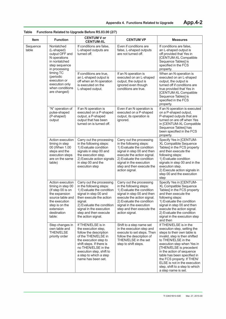
Appendix 4. Functions Related to Upgrade App.4-2
TI 33K01B10-50E
Table Functions Related to Upgrade Before R5.03.00 (2/7)
Item Function CENTUM V orCENTUM-XL CENTUM VP Measures
Sequence table
Nonlatched (L-shaped) output OFF and N operations in nonlatched step sequence in processing timing TC (periodic execution or execution only when conditions are changed)
If conditions are false, L-shaped outputs are turned off.
Even if conditions are false, L-shaped outputs are not turned off.
If conditions are false, an L-shaped output is off provided that Yes in [CENTUM-XLCompatibleSequence Tables] is specifiedintheFCSproperty.
If conditions are true, an L-shaped output is off when an N operation is executed on the L-shaped output.
If an N operation is executed on an L-shaped output, the output is ignored even though conditions are true.
When an N operation is executed on an L-shaped output, the output is turned off if conditions are true provided that Yes in [CENTUM-XLCompatibleSequence Tables] is specifiedintheFCSproperty.
“N” operation of pulse-shaped (P-shaped) output
If an N operation is executed on a P-shaped output, a P-shaped output that has been turned on is turned off.
Even if an N operation is executed on a P-shaped output, its operation is ignored.
If an N operation is executed on a P-shaped output, P-shaped outputs that are turned on are off when Yes in[CENTUM-XLCompatibleSequence Tables] has beenspecifiedintheFCSproperty.
Action execution timing in step 00 (When 1.00 steps and the execution steps are on the same table)
Carry out the processing in the following steps: 1) Evaluate condition signals in step 00 and the execution step. 2) Execute action signals in step 00 and the execution step
Carry out the processing in the following steps: 1) Evaluate the condition signal in step 00 and then execute the action signal. 2) Evaluate the condition signal in the execution step and then execute the action signal.
SpecifyYesin[CENTUM-XL Compatible Sequence Tables] in the FCS property and then execute the following steps: 1) Evaluate condition signals in step 00 and in the execution step. 2) Execute action signals in step 00 and the execution step
Action execution timing in step 00 (If step 00 is on the expansion source table and the execution step is on the extension destination table:
Carry out the processing in the following steps: 1) Evaluate the condition signal in step 00 and then execute the action signal. 2) Evaluate the condition signal in the execution step and then execute the action signal.
Carry out the processing in the following steps: 1) Evaluate the condition signal in step 00 and then execute the action signal. 2) Evaluate the condition signal in the execution step and then execute the action signal.
SpecifyYesin[CENTUM-XL Compatible Sequence Tables] in the FCS property and then execute the following steps: 1) Evaluate the condition signal in step 00 and then execute the action signal. 2) Evaluate the condition signal in the execution step and then
Step changes in own table and THEN/ELSE priority order
If THEN/ELSE is in the execution step, follow the description of the THEN/ELSE in the execution step to shift steps. If there is no THEN/ELSE in the execution step, shift to a step to which a step name has been set.
Shift to a step name set in the execution step and execute to set steps. Then follow the description of THEN/ELSE in the set step to shift steps.
If THEN/ELSE is in the execution step, setting the steps to their own table is invalid, step is then shifted to THEN/ELSE in the execution step when Yes in [THEN/ELSEisprecedentin the action of sequence tablehasbeenspecifiedinthe FCS property. If THEN/ELSE is not in the execution step, shift to a step to which a step name is set.
Mar. 27, 2015-00
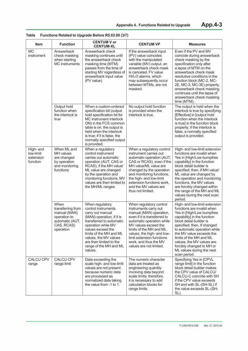
Appendix 4. Functions Related to Upgrade App.4-3
TI 33K01B10-50E
Table Functions Related to Upgrade Before R5.03.00 (3/7)
Item Function CENTUM V orCENTUM-XL CENTUM VP Measures
MC instrument
Answerback check masking when starting MC instruments
Answerback check masking continues until the answerback check masking time (MTM) passes from the time of starting MV regardless of answerback input value (PV value).
If the answerback input (PV) value coincides with the manipulated variable (MV) output, an answerback check mask is canceled, FV value HI/LO alarms, which may subsequently occur between MTMs, are not masked.
Even if the PV and MV coincide during answerback check masking by the specificationonlyaftera lapse of MTM on the answerback check mask resolutive conditions in the function block (MC-2, MC-2E, MC-3, MC-3E) property, answerback check masking continues until the lapse of answerback check masking time (MTM).
Output hold function when the interlock is true
When a custom-ordered specificationbit(outputholdspecificationbitforMC instrument interlock ON) in the FCS common table is on, the output is held when the interlock istrue;ifitisfalse,thenormallyspecifiedoutputis provided.
No output hold function is provided when the interlock is true.
The output is held when the interlock is true by specifying [Effective]in[outputholdfunction when the interlock is true] in the function block property;iftheinterlockisfalse,anormallyspecifiedoutput is provided.
High- and low-limit extension function
When ML and MH values are changed by operation and monitoring functions
When a regulatory control instrument carries out automatic operation (AUT, CAS or RCAS), if the MH value/ML value are changed by the operation and monitoring functions, MV values are then limited to the MH/ML ranges.
When a regulatory control instrument carries out automatic operation (AUT, CAS or RCAS), even if the MH value/ML value are changed by the operation and monitoring functions, the high- and low-limit extension functions work, and the MV values are thus not limited.
High- and low-limit extension functions are invalid when Yesin[High/Lowbumpfreecapability] in the function block detail builder is specified;then,ifMHvalue/ML value are changed by the operation and monitoring functions, the MV values are forcibly changed within the range of the MH and ML values during the next scan period.
When transferring from manual (MAN) operation to automatic (AUT, CAS, RCAS) operation
When regulatory control instruments carry out manual (MAN) operation, if it is transferred to automatic operation while MV values exceed the limits of the MH and ML values, the MV values are then limited to the range of the MH and ML values.
When regulatory control instruments carry out manual (MAN) operation, even if it is transferred to automatic operation while MV values exceed the limits of the MH and ML values, the high- and low-limit extension functions work, and thus the MV values are not limited.
High- and low-limit extension functions are invalid when Yesin[High/Lowbumpfreecapability] in the function block detail builder is specified;then,ifchangedto automatic operation while the MV value exceeds the limits of the MH and ML values, the MV values are forcibly changed to MH or ML values during the next scan period.
CALCU CPV range
CALCU CPV range limit
Data exceeding the scale high- and low-limit values are not present because numeric data are processed as normalized data taking the value from -1 to 1.
The numeric character data are treated as engineering quantity involving data beyond scalelimits;therefore,it is necessary to add calculation blocks for range limits.
SpecifyingYesin[CPVLrange limit] in the function block detail builder makes the CPV value of CALCU/CALCU-C coincide with SH if the CPV value exceeds SH and with SL-(SH-SL) if the value exceeds SL-(SH-SL).
Mar. 27, 2015-00

Appendix 4. Functions Related to Upgrade App.4-4
TI 33K01B10-50E
Table Functions Related to Upgrade Before R5.03.00 (4/7)
Item Function CENTUM V orCENTUM-XL CENTUM VP Measures
SUB output terminal
SUB output terminal∆PVcalculation
SUB terminal provides the following output if an IOP occurs: ∆PV=0or∆CPV=0
If an IOP occurs, the function block provides ∆PV(calculationblockprovides∆CPVoutput)even when PV value overshooting occurs. (If overshooting does not occur,both∆PVand∆CPVare0asPVvaluesdo not change even if an IOP occurs.)
When the FCS property’s [dPV/dCPVOutputfromSUBBecomesZeroRightAfter IOP] checkbox ON is specified,theSUBterminalprovides∆PV=0or∆CPV= 0 output when an IOP occurs.
Totalizer data Data set to totalizer value
Even if the instrument totalizer “NO” is specified,itispossibletoset data to SUM values.
If the function block totalizer“NO”isspecified,it is not possible to set data to SUM values.
Specifyingthe[SumValueEntry] menu in the function block detail builder makes data setting to SUM values from HIS possible.
CALCU/ CALCU-C pulse train input
Totalizer data specificationwith pulse train inputs (batch data totalizer type)
– If the pulse train input (batch data totalizer) is selected with CALCU, RV rather than CPV is used for totalization.
IfCPVinthe[DataItemforTotalization] menu in the function block detail builder isspecified,CPVisusedfortotalization.
PID-TP instrument
PID-TP control algorithm
The method of selecting control algorithms differs between CENTUM-XL and CS or later systems, so differential control action results in CAS mode. In CS or later systems, only PV proportional and derivative-typePIDcontrol(I-PD)isused(fixed).AbuildersuchasaPIDblockcannotbespecified.
The[PIDcontrolalgorithms]menu in the function block detail builder allows the selection of control algorithms identical to PID algorithms, as given below: • ProportionalPVDerivative
Type PID Control • PVDerivativePIDControl• BasicTypeID• AutomaticDetermination2• AutomaticDetermination
Output action – Positionaltype(fixed) [AuxiliaryOutputType]menu in the function block detail builder allows the selection of positional or velocity output action.
BSETU compatible mode `
Starting/restarting blocks by sequence table action
BSETU/7BS Start: LOOP = AUT, SV = 0 Suspend: LOOP = CAS Restart: LOOP = AUT Reset: LOOP = MAN
BSETU-2/3 Start: MODE = AUT, SW = 1 Suspend: SW = 4 Restart: SW = 2 Reset: SW = 3
Specifying[CENTUMV/CENTUM-XL Compatible] in the function block detail builder allows batch starting or restarting depending on the conditions with ACT.ON descriptions on the sequence table, or the like.
Restart during EMST
Restart is accepted even during EMST.
Does not restart under ZONE8(duringEMSTor while MV values are decreasing).
Specifying[CENTUMV/CENTUM-XL Compatible] or [CENTUM-XLCompatible]in the function block detail builder can accept restart instructions when BSTS = EMST (while MV values are decreasing in an emergency stop).
Mar. 27, 2015-00

Appendix 4. Functions Related to Upgrade App.4-5
TI 33K01B10-50E
Table Functions Related to Upgrade Before R5.03.00 (5/7)
Item Function CENTUM V orCENTUM-XL CENTUM VP Measures
BSETU compatible mode
Batch alarm when batch end is not complete.
7BS Batch end: ALRM=HI Pre-batch: ALRM=LO BSETU Batch end: ALRM=END Pre-batch: ALRM=PRE
BSETU-2/3 Batch end: BSTS=NCNT or END Pre-batch: BSTS=ERLY or PBCH
Specifying[CENTUMV/CENTUM-XL Compatible] or [XLcompatibleCENTUM-XLCompatible ] in the function block detail builder allows the transmission of a batch end alarm when the batch ends even if the batch end conditions(SUM≥ BSET-LPV)arenotsatisfied.
Pre-batch alarm when the batch ends.
After the pre-batch transmission, the pre-batch returns at the time of pre-batch end.
Pre-batch does not return at the time of pre-batch end, but, it returns simultaneously at the time of batch end when the next batch starts.
Specifying[CENTUMV/CENTUM-XL Compatible] in the function block detail builder allows the pre-batch alarm return when the batch ends.
Handling MV values when transferring from MAN to AUT mode
MV-value handling when transferring to MAN and then back to AUT differs between CENTUM-XL or earlier systems and CS or later systems.
Specifying[CENTUMV/CENTUM-XL Compatible] or [XLcompatibleCENTUM-XLCompatible ] in the function block detail builder allows the change of MV values when transferring from MAN to AUT mode.
Acceptance of batch end during EMST
– CS can specify whether or not accepting batch end during EMST, whereas CS 3000 or later systems can specifyspecificforms.
Specifying “Not accepted” in[AcceptBatch-EndduringEMST] in the FCS property allowsspecificationofthepresence or absence of accepting batch end during EMST.
Way to restart batch operation
The ways to restart batch operations differ between CENTUM-XL or earlier systems and CENTUM CS or a later system.
Specifying[CENTUMV/CENTUM-XL Compatible] or [CENTUM-XLCompatible]in the function block detail builder, or specifying Yes inthe[StartfromMLvalueat the time of restart] menu allows starting with ML values when restarting batch operation.
Way to batch start in cascade connections
Thewaystobatchstartwhen[BatchstartinBSETU-2/3]and[CASsetinfunctionblockfor destination cascade connections] are set simultaneously in cascade connections differ between CENTUM-XL or earlier systems and CENTUM CS or later systems.
Specifying[CENTUMV/CENTUM-XL Compatible or [CENTUM-XLCompatible]in the function block detail builder, or specifying Yes inthe[StartfromMLvalueat the time of restart] menu allows starting with ML values when starting batch processingwhen[Batchstart in BSETU-2/3] and [CASsetinfunctionblockfor destination cascade connections] are set simultaneously in cascade connections.
Sending of pre-batch alarms during EMST
The method of sending pre-batch alarms during EMST differs between CENTUM-XL or earlier systems and CENTUM CS or later systems.
Specifying[CENTUM-XLCompatible] in the function block detail builder stops pre-batch alarms from being transmitted during EMST.
Mar. 27, 2015-00
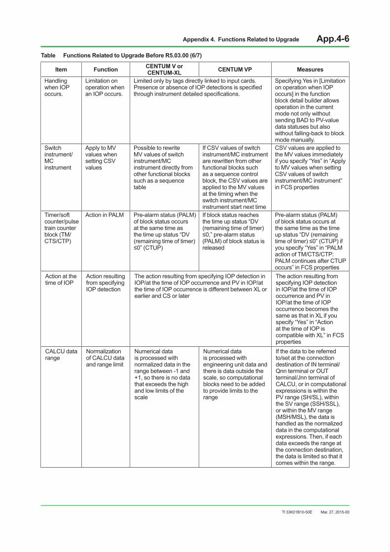
Appendix 4. Functions Related to Upgrade App.4-6
TI 33K01B10-50E
Table Functions Related to Upgrade Before R5.03.00 (6/7)
Item Function CENTUM V orCENTUM-XL CENTUM VP Measures
Handling when IOP occurs.
Limitation on operation when an IOP occurs.
Limited only by tags directly linked to input cards. PresenceorabsenceofIOPdetectionsisspecifiedthroughinstrumentdetailedspecifications.
SpecifyingYesin[Limitationon operation when IOP occurs] in the function block detail builder allows operation in the current mode not only without sending BAD to PV-value data statuses but also without falling-back to block mode manually.
Switch instrument/MC instrument
Apply to MV values when setting CSV values
Possible to rewrite MV values of switch instrument/MC instrument directly from other functional blocks such as a sequence table
If CSV values of switch instrument/MC instrument are rewritten from other functional blocks such as a sequence control block, the CSV values are applied to the MV values at the timing when the switch instrument/MC instrument start next time
CSV values are applied to the MV values immediately if you specify “Yes” in “Apply to MV values when setting CSV values of switch instrument/MC instrument” in FCS properties
Timer/soft counter/pulse train counter block (TM/CTS/CTP)
Action in PALM Pre-alarm status (PALM) of block status occurs at the same time as the time up status “DV (remaining time of timer) ≤0”(CTUP)
If block status reaches the time up status “DV (remaining time of timer) ≤0,”pre-alarmstatus(PALM) of block status is released
Pre-alarm status (PALM) of block status occurs at the same time as the time up status “DV (remaining timeoftimer)≤0”(CTUP)ifyou specify “Yes” in “PALM action of TM/CTS/CTP: PALM continues after CTUP occurs” in FCS properties
Action at the time of IOP
Action resulting from specifying IOP detection
The action resulting from specifying IOP detection in IOP/at the time of IOP occurrence and PV in IOP/at the time of IOP occurrence is different between XL or earlier and CS or later
The action resulting from specifying IOP detection in IOP/at the time of IOP occurrence and PV in IOP/at the time of IOP occurrence becomes the same as that in XL if you specify “Yes” in “Action at the time of IOP is compatible with XL” in FCS properties
CALCU data range
Normalization of CALCU data and range limit
Numerical data is processed with normalized data in the range between -1 and +1, so there is no data that exceeds the high and low limits of the scale
Numerical data is processed with engineering unit data and there is data outside the scale, so computational blocks need to be added to provide limits to the range
If the data to be referred to/set at the connection destination of IN terminal/Qnn terminal or OUT terminal/Jnn terminal of CALCU, or in computational expressions is within the PV range (SH/SL), within the SV range (SSH/SSL), or within the MV range (MSH/MSL), the data is handled as the normalized data in the computational expressions. Then, if each data exceeds the range at the connection destination, the data is limited so that it comes within the range.
Mar. 27, 2015-00
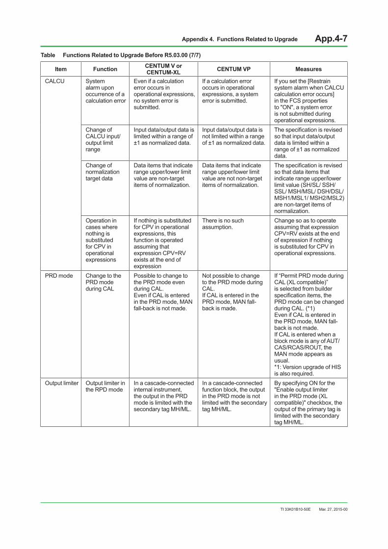
Appendix 4. Functions Related to Upgrade App.4-7
TI 33K01B10-50E Mar. 27, 2015-00
Table Functions Related to Upgrade Before R5.03.00 (7/7)
Item Function CENTUM V orCENTUM-XL CENTUM VP Measures
CALCU System alarm upon occurrence of a calculation error
Even if a calculation error occurs in operational expressions, no system error is submitted.
If a calculation error occurs in operational expressions, a system error is submitted.
Ifyousetthe[Restrainsystem alarm when CALCU calculation error occurs] in the FCS properties to "ON", a system error is not submitted during operational expressions.
Change of CALCU input/output limit range
Input data/output data is limited within a range of ±1 as normalized data.
Input data/output data is not limited within a range of ±1 as normalized data.
Thespecificationisrevisedso that input data/output data is limited within a range of ±1 as normalized data.
Change of normalization target data
Data items that indicate range upper/lower limit value are non-target items of normalization.
Data items that indicate range upper/lower limit value are not non-target items of normalization.
Thespecificationisrevisedso that data items that indicate range upper/lower limit value (SH/SL/ SSH/SSL/ MSH/MSL/ DSH/DSL/ MSH1/MSL1/ MSH2/MSL2) are non-target items of normalization.
Operation in cases where nothing is substituted for CPV in operational expressions
If nothing is substituted for CPV in operational expressions, this function is operated assuming that expression CPV=RV exists at the end of expression
There is no such assumption.
Change so as to operate assuming that expression CPV=RV exists at the end of expression if nothing is substituted for CPV in operational expressions.
PRD mode Change to the PRD mode during CAL
Possible to change to the PRD mode even during CAL.Even if CAL is entered in the PRD mode, MAN fall-back is not made.
Not possible to change to the PRD mode during CAL.If CAL is entered in the PRD mode, MAN fall-back is made.
If “Permit PRD mode during CAL (XL compatible)” is selected from builder specificationitems,thePRD mode can be changed during CAL. (*1)Even if CAL is entered in the PRD mode, MAN fall-back is not made.If CAL is entered when a block mode is any of AUT/CAS/RCAS/ROUT, the MAN mode appears as usual.*1: Version upgrade of HIS is also required.
Output limiter Output limiter in the RPD mode
In a cascade-connected internal instrument, the output in the PRD mode is limited with the secondary tag MH/ML.
In a cascade-connected function block, the output in the PRD mode is not limited with the secondary tag MH/ML.
By specifying ON for the "Enable output limiter in the PRD mode (XL compatible)" checkbox, the output of the primary tag is limited with the secondary tag MH/ML.

Appendix 5. Glossary App.5-1
TI 33K01B10-50E
Appendix 5. GlossaryThis is a glossary of abbreviations and acronyms about Yokogawa products that are mentioned in this document.
Table Glossary(1/2)
Abbreviation or Acronym Description
ACG CENTUM VP Communication gateway with supervisory computerANB10S, ANB10D CENTUM VP Node unit for FIO (Single/Duplexed)ANR10S, ANR10D CENTUM VP Remote node unit for FIO (Single/Duplexed)
APCS Advanced Process Control Station (Station on a PC platform, mainly intended to perform plant advanced control)
BCV-H Converter between V net and HF busBRAIN communication Function to communicate with BRAIN Series products supported with CENTUM-XLCCMS CENTUM V Computer stationCFBS2 CENTUMVCompactfieldcontrolstationCFCS2, CFCD2 CENTUM V Field control station (Single/Duplexed)CFGW CENTUM V Field gateway unitCFSS, CFSD CENTUM V Field control station for sequence control (Single/Duplexed)CGWU CENTUM V Gateway unit for communication with higher-level systems (-1, -2, -3 models)COPSV CENTUM V Operation & monitoring stationECGWZ,ECGW2,ECGW3 CENTUM-XL Gateway units for communication with higher-level systems
ECMP CENTUM-XL Computer stationsEFCS, EFCD CENTUM-XL Field control station (-S1, -H2, -H4 models) (Single/Duplexed)EFGW CENTUM-XL Field gateway unitEFUS, EFUD CENTUM-XLCompactfieldcontrolstation(Single/Duplexed)EMCS, EMCD CENTUM-XL Master control station (Single/Duplexed)ENG CENTUM VP Engineering stationENGS CENTUM-XL Engineering stationEOPS CENTUM-XL Operation & monitoring station
ER bus I/O bus that connects remote connection card installed in Node Unit for FIO to Remote Node Unit for FIO
ESB bus I/O bus that connects CPU in Field Control Unit (SCN) to Node Unit for FIO.Exaopc OPC interface packageExapro Expert system building support toolExaquantum Plant information management systemFCS Field Control Station (generally used for CENTUM series.)FCU Fieldcontrolunit;theCPUofanFCSoftheCENTUMVP.FFCS, FFCD CENTUM VP Field control station (Single/Duplexed)FIO I/OforCENTUMVP’sfieldcontrolstationFMS Field Monitoring Station (generally used for CENTUM series.)HF bus Control bus used in CENTUM V and CENTUM-XL systemsHIS CENTUM VP Operation & monitoring station
HKU House Keeping Unit (Collects alarm information, changes and collects SC setting informationinCENTUM-XLfieldcontrolstation.)
IOM I/O Module for CENTUM VPKFCS Field control station for CENTUM VP
KFCS-V An FCS which was of the CENTUM V and has been upgraded to CENTUM VP's FCS with16-MBRAM;alsoreferredtoasupgradedFCS-V.
KFCS2-V An FCS which was of the CENTUM V and has been upgraded to CENTUM VP's FCS with32-MBRAM;alsoreferredtoasupgradedFCS2-V.
KFCS-XL An FCS which was of the CENTUM-XL and has been upgraded to CENTUM VP's FCSwith16-MBRAM;alsoreferredtoasupgradedFCSXL.
KFCS2-XL An FCS which was of the CENTUM-XL and has been upgraded to CENTUM VP's FCSwith32-MBRAM;alsoreferredtoasupgradedFCS2-XL.
Mar. 27, 2015-00

Appendix 5. Glossary App.5-2
TI 33K01B10-50E
Table Glossary(2/2)
Abbreviation or Acronym Description
L2SW Layer 2 switch for network. Yokogawa dedicated L2SW is used for Vnet/IP.
LCS Loop Communication card (card for communication with single-loop controller such as SLCD. Used in CENTUM V and CENTUM-XL systems.)
LCULoop Communication card with ULDU Loop Display Unit used in CENTUM V and CENTUM-XL systems LD1 Loop Display interface card used in CENTUM V and CENTUM-XL systems
MCU Monitoring station Control Unit (core component of FMS) upgraded FCS2-V See KFCS2-V.
Upgraded FCS2-XL See KFCS2-XL.Upgraded FCS-V See KFCS-V.Upgraded FCS-XL See KFCS-XL.NC3, NC4 Nest Common card (I/O nest common card for CENTUM V and CENTUM-XL)PDB Power Distribution BoardPREDICTROL Predictive control function supported with CENTUM-XLProSafe-RS Safety instrumentation systemSB301, SB302 ESB bus interface card for CENTUM VP
SC SignalConditioner(InCENTUMVandCENTUM-XLsystems,installedbetweenfieldequipment and I/O card and converts signals.)
SCN Stationcontrolnest;theCPUofafieldcontrolstation(FCS)oftheCENTUMVandCENTUM-XL.
SEBOL Sequence & Batch Oriented Language (Language for sequence control)SFCS, SFCD CompactfieldcontrolstationforCENTUMVPSI bus Control bus that connects SCN and I/O nest in FCS of CENTUM V and CENTUM-XLSIO I/OforCENTUMVandCENTUM-XLfieldcontrolstationSTC Self Tuning Control (Control function with automatic PID tuning)V net Control bus used in CENTUM CS, CENTUM CS 3000 and CENTUM VP systemsVnet/IP Control bus for CENTUM VP, using Ethernet technologyXLAIS CENTUM-XL AI control stationXL-Batch Software package for batch processes, supported with CENTUM-XLYEWLINK Optical communication system
Mar. 27, 2015-00

i
TI 33K01B10-50E
Revision InformationTitle: A Guide for Upgrading CENTUM V and CENTUM-XL to CENTUM VP (for Vnet/IP)Manual No.: TI 33K01B10-50E
Mar. 2015/1st EditionNewly published (correspondence to Japanese 3rd Edition)
Mar. 27, 2015-00

Written by Yokogawa Electric Corporation
Published by Yokogawa Electric Corporation 2-9-32 Nakacho, Musashino-shi, Tokyo 180-8750, JAPAN
Printed by KOHOKU PUBLISHING & PRINTING INC.
Subject to change without notice.