technical bulletin - acasa - tm inox, relaţii...
TRANSCRIPT

Unit with low environmental impact andreduced refrigerant charge
Electronic expansion valve
Extensive range of operationContributes to achieving LEED points
<
<
<
<
NX_0152P_0812P_201205_EN
(The photo of the unit is purely indicative and may vary depending on the model)
Climaveneta Technical Bulletin
0152P - 0812P Air-source liquid chiller for outdoor installation, with plate heatexchanger39 ÷ 226 kW
NX

NXSUMMARY
HFC 410ANX_0152P_0812P_201205_EN2
1. CERTIFICATION LEED p. 3
2. DESCRIPTION OF THE UNIT 4
3. MODELS AND VERSIONS 43.1 Compact versions with standard efficiency 43.2 Compact versions with high efficiency 4
4. HOW TO SELECT THE NX 5
5. CROSS-REFERENCE TABLE 6
6. GENERAL CHARACTERISTICS 6
7. FUNCTIONS 7
8. VERSIONS 7
9. TECHNICAL SPECIFICATIONS 8
10. ACCESSORIES 10
11. TECHNICAL DATA 11
12. FAN STRUCTURE AND CONTROL 24
13. OPERATING LIMITS 25
14. ETHYLENE GLYCOL MIXTURE 26
15. FOULING FACTORS 26
16. HYDRAULIC DATA 27
17. HYDRONIC GROUP (Optional) 31
18. ELECTRICAL DATA 57
19. FULL LOAD SOUND LEVEL 60
20. DIMENSIONAL DRAWINGS 66
Please fill out the requested informationPlease fill out the requested information
Waiver of liabilityThis publication represents a preliminary document, and is thesole property of Climaveneta. Any reproduction or disclosure ofsuch is strictly prohibited without the written authorisation of Cli-maveneta.This document has been prepared with maximum care andattention paid to the content shown. Nonetheless, Climavenetawaives all liability deriving from the use of such document.Read this document carefully.
All work must be performed, components selected and materi-als used professionally and in complete accordance with thelegislation in force in material in the country concerned, andconsidering the operating conditions and intended uses of thesystem, by qualified personnel.The data contained in this publication may be changed withoutprior notice.
This company participates in the Eurovent Certifi cation Programme.The products are listed in the Directory of certifi ed products.Eurovent certifi cation applied to units with cooling capacity up to 1500 kWfor air cooled water chillers and water cooled liquid chillers.
Company quality systemcertified to UNI EN ISO 9001and environmental certification
UNI EN ISO 14001

NX_0152P_0812P_201205_EN HFC 410A3
NX1. CLIMAVENETA, THE MOST PROFITABLE WAYTO IMPROVE THE LEED CERTIFICATION OFYOUR BUILDING
Climaveneta is a Green Building Council Italy member andactively supports the diffusion of LEED practice all around theworld.Climaveneta High and Premium efficiency products and sys-tems are designed with special care to LEED protocol compli-ance and can help to achieve and improve the LEED certifica-tion of the building.In particular Climaveneta High and Premium efficiency productsand systems meet the LEED prerequisites for Energy & Atmos-phere (EA) and Indoor Environmental Quality (EQ) and canhelp to gather LEED points with regard to following areas:
ENERGY & ATMOSPHERE (EA)24 HVAC related LEED NC (New Construction and major Reno-vation Projects) points possible:• EA Prerequisite 2 – Minimum Energy Performance• EA Prerequisite 3 – Fundamental Refrigerant Management• EA Credit 1 – Optimize Energy Performance - 1 to 19 Points• EA Credit 4 - Enhanced Refrigerant Management - 1 to 2Points
• EA Credit 5 – Measurement & Verification – 1 to 3 Points
INDOOR ENVIRONMENTAL QUALITY (EQ)6 HVAC related LEED points possible• EQ Prerequisite 1 – Minimum Indoor Air Quality Performance• EQ Credit 1 – Outdoor Air Delivery Monitoring – 1 Point• EQ Credit 2 – Increased Ventilation – 1 Point• EQ Credit 5 – Indoor Chemical & Pollutant Source Control – 1Point
• EQ Credit 6.2 – Controllability of Systems: Thermal Comfort –1 Point
• EQ Credit 7.1 – Thermal Comfort: Design – 1 Point• EQ Credit 7.1 – Thermal Comfort: Verification – 1 Point
There are already several buildings LEED certified also thanksto Climaveneta HVAC systems. For more information, browsethe project list at www.climaveneta.com.

NX
HFC 410ANX_0152P_0812P_201205_EN4
2. DESCRIPTION OF THE UNIT
NX /K: NEW COMPACT LIQUID CHILLERSNX is the new Climaveneta liquid chiller, available in the new Kversion, combining the two main features of this unit: efficiencyand compactness.NX in fact achieves excellent levels of energy efficiency while atthe same time occupying less area, making this unit the bestsolution in all installations where there is limited space avail-able.Along with its compact dimensions, NX also comes in three ver-sions with different sound emission ratings, so as to comply withthe strictest installation requirements.The LN and SL versions reduce noise levels by up to 10dB(A)compared to the most compact version, making the NX the ide-al solution for satisfying the most demanding installation needsnot only in terms of efficiency and compactness, but also lownoise.This ensures maximum installation flexibility, an essentialrequirement when operating in restricted spaces or whenreplacing or upgrading existing systems.
NX/CA: NEW HIGH EFFICIENCY LIQUID CHILLERS WITHENERGY CLASS AWhen energy efficiency is a fundamental prerequisite, the Cli-maveneta NX/CA represents the best solution, ensuring thehighest efficiency in its category, with Eurovent class A EER val-ues, calculated based on the restrictive European standardEN14511.NX/CA also features three different versions as regards soundemissions.In addition to the standard version, two further versions can beselected, LN-CA and SL-CA, which reduce noise by up to10dB(A) while maintaining the same energy efficiency class.Indeed the main new feature that distinguishes the ClimavenetaNX/CA units from other products available on the market is theavailability of a complete selection of versions with differentsound emissions however without affecting the energy efficien-cy class, rather maintaining exceptional efficiency, all ratedEurovent class A.
3. MODELS AND VERSIONS
3.1 Compact versions with standard efficiency
NX/K: liquid chiller with standard efficiency, compactversion
NX/LN-K: liquid chiller with standard efficiency, compactand low noise version
NX/SL-K: liquid chiller with standard efficiency, compactand Super low noise version
NX/D /K: liquid chiller with standard efficiency, compactversion, including desuperheater for partialrecovery of the heat of condensation
NX/D /LN-K: liquid chiller with standard efficiency, compactand low noise version, including desuper-heater for partial recovery of the heat of con-densation
NX/D /SL-K: liquid chiller with standard efficiency, compactand Super low noise version, including desu-perheater for partial recovery of the heat ofcondensation
3.2 Compact versions with high efficiency
NX /CA: liquid chiller with high efficiency, compact ver-sion
NX /LN-CA: liquid chiller with high efficiency, compact andlow noise version
NX /SL-CA: liquid chiller with high efficiency, compact andSuper low noise version
NX /D /CA: liquid chiller with high efficiency, compact ver-sion, including desuperheater for partialrecovery of the heat of condensation
NX /D /LN-CA: liquid chiller with high efficiency, compact andlow noise version, including desuperheater forpartial recovery of the heat of condensation
NX /D /SL-CA: liquid chiller with high efficiency, compact andSuper low noise version, including desuper-heater for partial recovery of the heat of con-densation
NX
5HFC 410ANX_0152P_0812P_201205_EN
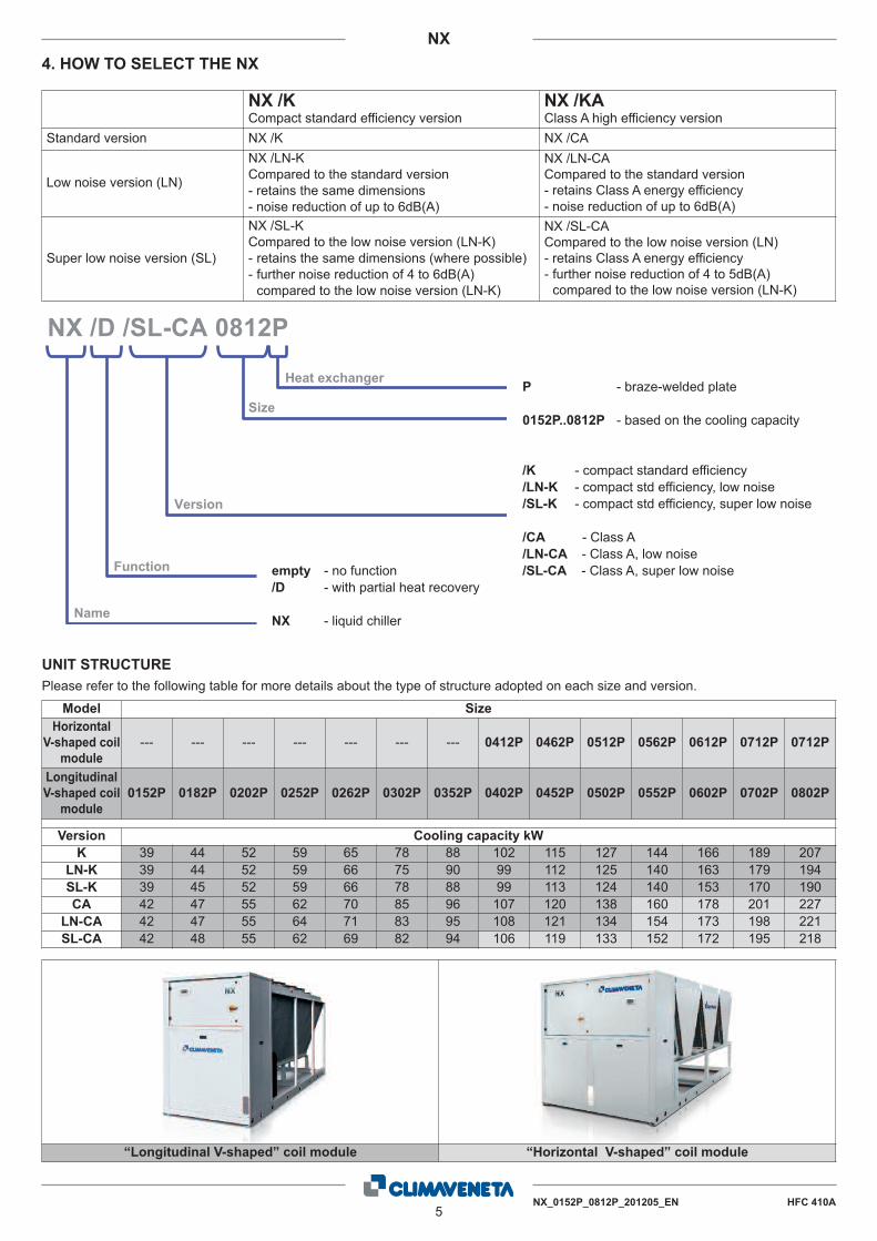
4. HOW TO SELECT THE NX
NX /KCompact standard efficiency version
NX /KAClass A high efficiency version
Standard version NX /K NX /CA
Low noise version (LN)
NX /LN-KCompared to the standard version- retains the same dimensions- noise reduction of up to 6dB(A)
NX /LN-CACompared to the standard version- retains Class A energy efficiency- noise reduction of up to 6dB(A)
Super low noise version (SL)
NX /SL-KCompared to the low noise version (LN-K)- retains the same dimensions (where possible)- further noise reduction of 4 to 6dB(A)compared to the low noise version (LN-K)
NX /SL-CACompared to the low noise version (LN)- retains Class A energy efficiency- further noise reduction of 4 to 5dB(A)compared to the low noise version (LN-K)
NX /D /SL-CA 0812P
Version
Function
Name
Size
Heat exchanger P - braze-welded plate
0152P..0812P - based on the cooling capacity
empty - no function/D - with partial heat recovery
NX - liquid chiller
/K - compact standard efficiency/LN-K - compact std efficiency, low noise/SL-K - compact std efficiency, super low noise
/CA - Class A/LN-CA - Class A, low noise/SL-CA - Class A, super low noise
UNIT STRUCTUREPlease refer to the following table for more details about the type of structure adopted on each size and version.
Model SizeHorizontal
V-shaped coilmodule
--- --- --- --- --- --- --- 0412P 0462P 0512P 0562P 0612P 0712P 0712P
LongitudinalV-shaped coil
module0152P 0182P 0202P 0252P 0262P 0302P 0352P 0402P 0452P 0502P 0552P 0602P 0702P 0802P
Version Cooling capacity kWK 39 44 52 59 65 78 88 102 115 127 144 166 189 207
LN-K 39 44 52 59 66 75 90 99 112 125 140 163 179 194SL-K 39 45 52 59 66 78 88 99 113 124 140 153 170 190CA 42 47 55 62 70 85 96 107 120 138 160 178 201 227
LN-CA 42 47 55 64 71 83 95 108 121 134 154 173 198 221SL-CA 42 48 55 62 69 82 94 106 119 133 152 172 195 218
“Longitudinal V-shaped” coil module “Horizontal V-shaped” coil module

NX
HFC 410ANX_0152P_0812P_201205_EN6
6. GENERAL CHARACTERISTICS5. CROSS-REFERENCE TABLE
Compliance with the strictest European standardsThe main new feature that distinguishes the new NX unitsregards the calculation methods used to define the energy effi-ciency values.These values are in fact now calculated not only based on thecapacity delivered and power consumed by the unit, but alsotaking into account heat exchanger pressure drop, or the avail-able pressure head if the unit is installed with pumps, asrequired by European standard EN14511.In this way, energy efficiency is no longer an index for evaluat-ing the unit alone, but rather extends the assessment by con-sidering the unit within the system, consequently taking intoaccount the energy required to pump the refrigerant or heat car-rier fluid used in the system.
Electronic expansion valve as standardThe electronic expansion valve brings significant benefits, espe-cially with variable loads and different outside climate condi-tions. Application of the valve on this unit is a result of specificdesign decisions regarding the refrigerant circuit configurationand optimisation of operation across a range of different operat-ing conditions. The electronic expansion valve is standard on allhigh efficiency CA versions, and optional on K versions.
Microchannel aluminium coilsThis new range of chillers uses aluminium micro-channel con-densing coils in all the units, ensuring extremely high efficiency.This means less refrigerant is needed compared to traditionalcopper coils, ensuring the lowest possible ratio between refrig-erant volume and cooling capacity delivered, making this prod-uct range unique in its reference market, at the same timeextending product life due to better resistance to corrosion byatmospheric agents.
“CLASS A” efficiencyThe entire range is available with class A energy rating. Allnoise-level configurations of the NX/CA guarantee high efficien-cy, through generous sizing of the heat exchange surfaces andprecise management of the ventilating coils.
Built-in hydronic unitThe built-in hydronic unit incorporates all the main water circuitcomponents.All sizes are in fact available in the configuration with one or twohigh/low pressure pumps, as well as with storage tank.
Extended operating rangeExtended operating range: operation at full load is guaranteedwith outside air temperatures up to 46°C.
Three sound emission levelsThe new NX appliances have three different sound emissionlevels. This means the best unit can be identified based onrequirements, according to the system where it will be installedand the application.
The following table shows the corresponding NX models for thecurrent NECS units.
NECS 0152..0612 NX 0152P..0812P
NECS /B NX /K compact version
NECS /LN NX /LN-K low noise
NECS /SL NX /SL-K super low noise
NECS /HT NX /CA high efficiency version
NECS /HL NX /LN-K low noise

NX
7HFC 410ANX_0152P_0812P_201205_EN
7. FUNCTIONS
Basic model(Unit without heat recovery)
Model with partial heat recovery (D)Air-cooled unit, complete with partial heat recovery.In this configuration a refrigerant/water heat exchanger is addedto the gas discharge line on every refrigerant circuit, comparedto the basic configuration.The heat exchanger, installed in series before the traditionalcondenser in the refrigerant circuit, is suitably sized to ensureheat recovery for hot water production at medium-high tempera-tures, for domestic or other uses.The heating capacity available is approximately equal to com-pressor power consumption.
8. VERSIONS
K – Compact with standard efficiencyKey efficiency, compact version.
LN-K - Compact with standard efficiency, low noiseKey efficiency, compact and low-noise version. This configura-tion features special soundproofing for the compressor chamberand pumps (if present) and a reduced fan speed. Fan speed isautomatically increased, however, in the event of particularlytough environmental conditions.
SL-K - Compact with standard efficiency, super low noiseKey efficiency, compact and super low-noise version. This con-figuration features special soundproofing for the compressorchamber and pumps (if present), reduced fan speed and anoversized condensing section. Fan speed is automaticallyincreased, however, in the event of particularly tough environ-mental conditions.
CA - Class AClass A high efficiency version according to Eurovent classifica-tion. This configuration features a larger condensing section.
LN-CA - Class A low-noiseClass A low-noise version in accordance with Eurovent.This configuration features special soundproofing for the com-pressor chamber and pumps (if present) and a reduced fanspeed. Fan speed is automatically increased, however, in theevent of particularly tough environmental conditions.
SL-CA - Class A super low-noiseClass A super low-noise version in accordance with Eurovent.This configuration features special soundproofing for the com-pressor chamber and pumps (if present), reduced fan speedand an oversized condensing section. Fan speed is automati-cally increased, however, in the event of particularly tough envi-ronmental conditions

NX
HFC 410ANX_0152P_0812P_201205_EN8
9. TECHNICAL SPECIFICATIONS
Air source chiller for outdoor installationOutdoor unit for the production of chilled water with hermeticrotary Scroll compressors, ozone-friendly refrigerant R410A,axial-flow fans, plate heat exchanger, micro-channel full-alu-minum air coils and thermostatic or electronic expansion valve,according to the model. The range is composed by unitsequipped with two compressors in a single-circuit configuration.
StructureStructure specifically designed for outdoor installation. Base-ment and frame in hot-galvanised shaped sheet steel with asuitable thickness. All parts polyester-powder painted to assuretotal weather resistance.
CompressorsHermetic scroll compressors in tandem layout complete with oilsump heater, electronic overheating protection with centralisedmanual reset and a two-pole electric motor.
User (side) heat exchanger waterAISI 316 steel braze-welded plate exchanger.The heat exchangers are insulated with a closed-cell condensa-tion proof lining in neoprene. A thermostatically controlled elec-tric heater prevents ice from forming inside the evaporator whenthe unit is not working. When the unit is working, it is protectedby a differential pressure switch mounted on the water side. Theunit can work with antifreeze mixtures at exchanger outlet tem-peratures as low as -8°C. The hydronic group includes the dif-ferential pressure switch.
Source (side) heat exchanger airFull-aluminum coil made by aluminum tubes and fins. The alu-minum fins are correctly spaced to guarantee optimum heatexchange efficiency. The differentiated circulation suitably dis-tributes the liquid in the coil during the expansion phase. Coilstructure made with an open-angle V-geometry layout.
Fan sectionAxial electric fans, protected to IP 54, with external rotor andplastic-coated aluminium blades. Housed in aerodynamic hoodscomplete with safety grille. 6 - pole electric motor with built-inoverload protection. Differentiated ventilation control disablingthe fan section of inactive circuits.Fans diameter: 450mm, 800mm, 910mm according to differentsizes and versions.Condensation control with adjustment of fan rotation speed.
Continuous adjustment of the fan speed on units:- versions K, sizes 0152P..0352P- versions LN-K, sizes 0152P..0302P- versions SL-K e LN-CA, sizes 0152P..0202P- versions CA, sizes 0152P..0262P
Pressostatic fan’s control:- versions K sizes 0402P..0802P
Adjustment of the fan speed with auto-transformer on units:- versions LN-K sizes 0352P..0802P- versions SL-K sizes 0252P..0802P- versions LN-CA sizes 0252P..0812P- versions SL-CA, sizes 0152P..0812P
Refrigerant circuitMain components of the cooling circuit:- single circuit in tandem compressors,
- R410A refrigerant,- total ratio between refrigerant charge and cooling capacity*lower than 0,12 g/W (versions K, LN-K, SL-K, CA)
- total ratio between refrigerant charge and cooling capacity*lower than 0,15 g/W (versions LN-CA, SL-CA)
- plate heat exchanger,- anti-freeze heaters on the heat-exchanger,- dehydrator filter,- coolant line sight glass with humidity indicator,- mechanical thermostatic expansion valves (versions K, LN-K,SL-K),
- electronic expansion valves (versions CA, LN-CA, SL-CA),- high and low pressure transducers,- high and low pressure gauges,- high pressure safety valve,- low pressure safety valve,- high pressure safety switches,- crankcase heater on each compressor.
* Cooling capacity according to Eurovent conditions: water(in/out)12/7°C, outdoor temperature 35°C.
Electrical panelElectric power and control panel, built to EN 60204-1/EC 204-1standards, complete with:- control circuit transformer,- numbered cables,- general door lock isolator,- electric circuit breakers for compressors and fans,- terminals for cumulative alarm block (BCA),- relays for remote pump(s) activation for both circuits (only forunits without hydronic pumps),
- spring-type control circuit terminal board,- electric panel with double door and seals for outdoor installa-tion,
- electrical board for outdoor installation,- electronic controller,- multi-language user keypad with LCD display,- IP43 protection,
Power input 400V/3/50HZ+N+PE for units:- versions K, sizes 0152P..0352P- versions LN-K, sizes 0152P..0302P- versions SL-K e LN-CA, sizes 0152P..0202P- versions CA, sizes 0152P..0262P
Power input 400V/3/50HZ+PE for units:- versions K sizes 0402P..0812P- versions LN-K sizes 0352P..0812P- versions SL-K e LN-CA sizes 0252P..0812P- versions SL-CA
Certification, Reference standardThe unit complies with the following directives and relativeamendments:- Machinery Directive: 2006/42/EC.- E.C.D. 89/336/EEC + 2004/108/EC.- Low Voltage Directive 2006/95/EC.- Pressure Equipment Directive 97/23/EC. Mod. A1. - TÜV-Italy0948
TestsTests performed throughout the production process, as indicat-ed in ISO9001.

NX
9HFC 410ANX_0152P_0812P_201205_EN
Performance or noise tests can be performed by highly qualifiedstaff in the presence of customers.Performance tests comprise the measurement of:- electrical data- water flow rates- working temperatures- power input- power output- pressure drops on the water-side exchanger both at full load(at the conditions of selection and at the most critical conditionsfor the condenser) and at part load conditions.During performance testing it is also possible to simulate themain alarm states.Noise tests are performed to check noise emissions accordingto ISO3744.
Electronic Controller (W3000 – W3000SE)The controller in two different versions according to the unit’stype:
W3000: electronic controller complete with keypad features aneasy-to-use interface and a complete LCD display, allowing toconsult and intervene on the unit by means of a menu up to threelanguages (Italian and English come standard, a further languagecan be chosen within French, Spanish, German, Russian andSwedish)
W3000SE: electronic controller complete with keypad features aneasy-to-use interface and a complete LCD display, allowing toconsult and intervene on the unit by means of a multi-languagemenu, with selectable language setting on site. This controlleralso includes an internal clock.
The W3000SE controller offers advanced functions and algo-rithms.The keypad features an easy-to-use interface and a completeLCD display, allowing to consult and intervene on the unit bymeans of a multi-level menu, with selectable language setting.
The regulation is based on the exclusive QuickMind algorithm,including self-adaptive control logics, beneficial in low water con-tent systems. As alternatives the proportional- or proportional-integral regulations are also available.
The diagnostics includes a complete alarm management, with the"black-box" and alarm logging functions for enhanced analysis ofthe unit operation (available on W3000SE only).For multiple units’ systems, the regulation of the resources, viaoptional proprietary devices, can be implemented. Energy meter-ing, for both consumption and capacity, can also be developed.Supervision can be easily developed via proprietary devices orthe integration in third party systems by means of the most com-mon protocols as ModBus, Bacnet, Bacnet-over-IP, Echelon Lon-Works.
Compatibility with the remote keyboard managing up to 10 units.The internal real time clock allows to manage a weekly scheduleoperating on 4-day profiles with 10 hour belts (available onW3000SE only, optional on W3000 controller).
The defrost adopts a proprietary self-adaptive logic, which fea-tures the monitoring of numerous operational parameters.This allows to reduce the number and duration of the defrostcycles, with a benefit for the overall energy efficiency.
Please refer to the following table for more details about the type of electronic controller adopted by each size and version.
Model SizeHorizontal
V-shaped coilmodule
--- --- --- --- --- --- --- 0412P 0462P 0512P 0562P 0612P 0712P 0712P
LongitudinalV-shaped coil
module0152P 0182P 0202P 0252P 0262P 0302P 0352P 0402P 0452P 0502P 0552P 0602P 0702P 0802P
Version Type of electronic controllorK W3000 W3000SE
LN-K W3000 W3000SESL-K W3000 W3000SECA W3000SE W3000SE
LN-CA W3000SE W3000SESL-CA W3000SE W3000SE

10NX_0152P_0812P_201205_EN HFC 410A
NX10. ACCESSORIES
ACCESSORIES DESCRIPTION BENEFIT
Cu/Cu condensing coils Air-refrigerant heat exchanger with copper fins andtubes. Recommended for applications in corrosive atmospheres
Condensing coils withepoxy-coated fins Painted air-refrigerant heat exchanger. Recommended for applications in medium level pollution
atmospheres.Condensing coils with FinGuard Silver treatment
Air-refrigerant heat exchanger with epoxidic treatmenton coils and fins.
Recommended for marine exposure conditions, with anhigh level of pollution or other aggressive atmospheres.
Soft start Electronic device adopted to manage the inrush cur-rent.
Break down of the inrush current as soon as the electricalmotor is switch on, lower motor's mechanical wear,favourable sizing for the electrical system.
Remote phase-sequencecontrol Relay for controlling the phase-sequence of mains. Protects loads against faults due to incorrect connection of
the electric line.
Compressors' on/off signal Auxiliary contacts providing a voltage-free signal Allows remote signalling of compressor's activation orremote control of any auxiliary loads.
ModBUS connectivity Interface module for ModBUS protocols Allows integration with BMS operating with ModBUS proto-col
BACnet connectivity Interface module for BACnet protocols Allows integration with BMS operating with BACnet protocol
Echelon connectivity Interface module for Echelon systems Allows integration with BMS operating with LonWorks pro-cotls
HP AND LP GAUGES High and low pressure gauges. Allows immediate reading of the pressure values on bothlow and high pressure circuits.
COMPRESSOR SUCTIONVALVE
Shut-off solenoid valve on compressor's suction cir-cuit. Simplifies maintenance activities
COMPR. DISCHARGE LINEVALVE
Shut-off solenoid valve on compressor discharge cir-cuit Simplifies maintenance activities.
Anti-intrusions grills Avoid the intrusion of solid bodies into the unit's structure
BACnet OVER IP connectivity Interface module for BACnet OVER-IP protocols Allows to interconnect BACnet devices over Internet Proto-col within wide-area networks
AUX 4-20mA REMOTE D L.C.
4..20mA analogue input, voltage-free digitale input.Allows to change the operating set-point according tovalue of current applied to 4..20mA input and to limitthe unit's power (by activating the digital input).
Enforce Energy Saving policy, ensure safety operation.
DVV
Fan speed control according to the condensing pressu-re; the use of this device is mandatory in case the unitoperates with low evaporator leaving water temperaturesetpoint further combined with a low outdoor temperatu-re [See the section "Operating limit" for more furtherinformation]
Increase of the unit global efficiency thanks to a more accu-rate fans speed management. Improvement of the quiet-ness in part load operating conditions. Extension of the unitoperating range ensuring a safe operation down to -10°Coutdoor air temperature.
DVVF
Fan speed control according to the condensing pres-sure; the use of this device is mandatory in case theunit operates with low evaporator leaving water tem-perature setpoint further combined with a low outdoortemperature [See the section "Operating limit" formore further information]
Increase of the unit global efficiency thanks to a more accu-rate fans speed management. Improvement of the quietnessin part load operating conditions. Extension of the unit opera-ting range ensuring a safe operation down to -10°C outdoorair temperature. Allows the unit to operate at even mostextreme conditions avoiding any risk of low pressure inter-vention.
DVV2F
Fan speed control according to the condensing pres-sure; the use of this device is mandatory in case theunit operates with low evaporator leaving water tem-perature setpoint further combined with a low outdoortemperature [See the section "Operating limit" formore further information]
Increase of the unit global efficiency thanks to a more accu-rate fans speed management. Improvement of the quietnessin part load operating conditions. Extension of the unit opera-ting range ensuring a safe operation down to -10°C outdoorair temperature. Allows the unit to operate at even mostextreme conditions avoiding any risk of low pressure inter-vention.
E-COATING MICROCHANNELCOILS
Air coil with aluminum tubes and fins with e-coatingprotection
Recommended for medium level of pollution or soft marineatmospheres.
COPPER/ALUMINUM COILS Air coil with copper tubes and aluminum fins ---
FLUID OUT BELOW -4 ° C Leaving water temperature lower than -4°C at outdoortemperature lower than 10°C
Allows to the unit to produce leaving water temperaturelower than -4°C when the outdoor temperature is lowerthan 10°C. Without this option the unit can't operate at thisspecific conditions.
ANTIFREEZE ON PIPESElectrical heaters on pipes .This option is mandatory ifthe unit is supposed to work with outdoor temperaturebelow 0°C
It protects the unit against ice formation on its hydrauliccomponents
ANTIFREEZE ON PIPESS +PUMP
Electrical heaters on pipes and other hydraulic unit'scomponents. This option is mandatory if the unit is sup-posed to work with outdoor temperature below 0°C
It protects the unit against ice formation on its hydrauliccomponents
ANTIFREEZE ON PIPES +PUMPS + TANK
Electrical heaters on pipes and water tank. This optionis mandatory if the unit is supposed to work with out-door temperature below 0°C
It protects the unit against ice formation on its hydrauliccomponents

NX_0152P_0812P_201205_EN HFC 410A11
NX11. TECHNICAL DATA
NX/K General technical data
(*) Performance based on EN14511-3:20111 Plant (side) cooling exchanger water (in/out) 12/7 °C
Source (side) heat exchanger air (in) 35 °C2 Plant (side) cooling exchanger water (in/out) 12/7 °C
Source (side) heat exchanger air (in) 35 °CPlant (side) heat exchanger recovery water (in/out) 40/45 °C
3 Sound power on the basis of measurements made in compliance with ISO 9614 and Eurovent 8/1 for Eurovent certified units; in compliance with ISO 3744 for non-certi-fied unitsAverage sound pressure level, at 10 (m.) distance, unit in a free field on a reflective surface; non-binding value obtained from the sound power level
4 Standard configuration- Not available
SIZE 0152P 0182P 0202P 0252P 0262P 0302P 0352P
COOLING (1)
Cooling capacity kW 39,2 44,3 51,9 58,9 65,0 77,6 88,5Total power input (unit) kW 13,5 15,6 18,1 20,5 23,5 26,8 31,3EERESEER
2,904,41
2,844,37
2,874,41
2,874,39
2,774,33
2,904,23
2,834,41
Heat exchanger water flow m³/h 6,76 7,62 8,94 10,1 11,2 13,4 15,2Heat exchanger pressure drop kPa 36,3 34,1 36,3 33,4 33,2 33,9 54,1
NX /K
NX /D /KCOOLING WITH PARTIAL RECOVERY (2)
Cooling capacity kW 40,7 45,9 53,9 61,1 67,4 80,5 91,8Total power input (unit) kW 13,0 15,1 17,5 19,8 22,7 25,9 30,3Heat exchanger water flow m³/h 6,76 7,62 8,94 10,1 11,2 13,4 15,2Heat exchanger pressure drop kPa 36,3 34,1 36,3 33,4 33,2 33,9 54,1Heat recovery thermal capacity kW 11,4 13,3 15,2 17,4 20,0 22,5 26,6Heat exchanger recovery water flow m³/h 1,98 2,30 2,65 3,03 3,48 3,92 4,63Plant side heat exchanger recovery pressure drop kPa 6,91 9,37 12,4 16,2 21,4 13,4 18,7
COMPRESSORSNumberNumber of capacityNumber of circuits N°.
N°.N°. 2 2 2 2 2 2 2
2 2 2 2 2 2 21 1 1 1 1 1 1
Type of regulation STEPS STEPS STEPS STEPS STEPSSTEPSSTEPS
8,16,86,86,86,86,85,4kg.Oil charge10,69,89,69,15,65,54,7kg.Refrigerant charge
R410AR410AR410AR410AR410AR410AR410AType of refrigerant% 50 50 50 50 50 50 50Minimum capacity steps
FANSNumberAir flow
N°.m³/s
3 3 4 4 4 6 63,91 3,91 4,92 5,32 5,32 7,41 7,41
0,250,250,250,250,250,250,25kWSingle power input
NOISE LEVELS (3)
Total sound power dB(A) 83 83 84 84 84 85 865452525151dB(A)Total sound pressure 5352
DIMENSIONS AND WEIGHTS (4)
LengthWidthHeightWeight
mm.mm.mm.kg.
175511951885470
175511951885480
175511951885490
229011951885540
229011951885550
229011951885570
229011951885660
COOLING (EN14511 VALUE) (1)
Cooling capacity kWEERESEER
NX /K(*)
EUROVENT Class
(
39,0 44,0 51,6 58,6 64,7 77,2 87,92,83 2,78 2,80 2,82 2,71 2,84 2,764,19 4,15 4,20 4,20 4,17 4,06 4,16
C C C C C C C

NX/K General technical data
(*) Performance based on EN14511-3:20111 Plant (side) cooling exchanger water (in/out) 12/7 °C
Source (side) heat exchanger air (in) 35 °C2 Plant (side) cooling exchanger water (in/out) 12/7 °C
Source (side) heat exchanger air (in) 35 °CPlant (side) heat exchanger recovery water (in/out) 40/45 °C
3 Sound power on the basis of measurements made in compliance with ISO 9614 and Eurovent 8/1 for Eurovent certified units; in compliance with ISO 3744 for non-certi-fied unitsAverage sound pressure level, at 10 (m.) distance, unit in a free field on a reflective surface; non-binding value obtained from the sound power level
4 Standard configuration- Not available
SIZE 0402P 0452P 0502P 0552P 0602P 0702P 0802P
COOLING (1)
Cooling capacity kW 102 114 127 144 166 189 207Total power input (unit) kW 35,4 40,1 44,9 52,3 57,7 67,9 77,9EERESEER
2,884,04
2,864,13
2,844,13
2,764,24
2,874,08
2,794,15
2,653,89
Heat exchanger water flow m³/h 17,6 19,7 21,9 24,8 28,5 32,6 35,6Heat exchanger pressure drop kPa 49,9 51,3 49,1 52,1 49,3 49,8 59,2
NX /K
NX /D /KCOOLING WITH PARTIAL RECOVERY (2)
Cooling capacity kW 106 119 132 150 172 197 214Total power input (unit) kW 34,3 38,9 43,5 50,6 55,8 65,7 75,4Heat exchanger water flow m³/h 17,6 19,7 21,9 24,8 28,5 32,6 35,6Heat exchanger pressure drop kPa 49,9 51,3 49,1 52,1 49,3 49,8 59,2Heat recovery thermal capacity kW 28,0 32,3 36,5 43,1 46,1 55,2 64,2Heat exchanger recovery water flow m³/h 4,86 5,61 6,35 7,49 8,01 9,60 11,2Plant side heat exchanger recovery pressure drop kPa 20,6 19,3 24,7 23,1 26,5 25,5 34,4
COMPRESSORSNumberNumber of capacityNumber of circuits N°.
N°.N°. 2 2 2 2 2 2 2
2 2 2 2 2 2 21 1 1 1 1 1 1
Type of regulation STEPS STEPS STEPS STEPS STEPSSTEPSSTEPS
10,610,612,613,113,611,59,4kg.Oil charge18,718,117,716,816,615,213,6kg.Refrigerant charge
R410AR410AR410AR410AR410AR410AR410AType of refrigerant% 50 50 50 50 50 50 50Minimum capacity steps
FANSNumberAir flow
N°.m³/s
2 2 2 2 3 3 311,3 11,3 11,3 11,7 17,0 17,0 17,0
2222222kWSingle power input
NOISE LEVELS (3)
Total sound power dB(A) 88 88 88 89 90 90 915958565656dB(A)Total sound pressure 5857
DIMENSIONS AND WEIGHTS (4)
LengthWidthHeightWeight
mm.mm.mm.kg.
282511952010830
282511952010870
282511952010900
336011952010980
3980119520101130
3980119520101110
3980119520101140
COOLING (EN14511 VALUE) (1)
Cooling capacity kWEERESEER
NX /K(*)
EUROVENT Class
(
101 114 127 144 165 189 2062,82 2,79 2,78 2,70 2,82 2,74 2,603,86 3,96 3,95 4,04 3,92 3,99 3,74
C C C C C C D
NX
HFC 410ANX_0152P_0812P_201205_EN12

NX/LN-K General technical data
(*) Performance based on EN14511-3:20111 Plant (side) cooling exchanger water (in/out) 12/7 °C
Source (side) heat exchanger air (in) 35 °C2 Plant (side) cooling exchanger water (in/out) 12/7 °C
Source (side) heat exchanger air (in) 35 °CPlant (side) heat exchanger recovery water (in/out) 40/45 °C
3 Sound power on the basis of measurements made in compliance with ISO 9614 and Eurovent 8/1 for Eurovent certified units; in compliance with ISO 3744 for non-certi-fied unitsAverage sound pressure level, at 10 (m.) distance, unit in a free field on a reflective surface; non-binding value obtained from the sound power level
4 Standard configuration- Not available
SIZE 0152P 0182P 0202P 0252P 0262P 0302P 0352P
COOLING (1)
Cooling capacity kW 39,3 44,3 51,7 58,8 65,5 74,7 89,9Total power input (unit) kW 13,6 15,8 18,5 20,4 23,2 28,3 31,1EERESEER
2,894,5
2,804,44
2,794,41
2,884,38
2,824,39
2,644,22
2,894,26
Heat exchanger water flow m³/h 6,76 7,64 8,90 10,1 11,3 12,9 15,5Heat exchanger pressure drop kPa 36,3 34,2 36,0 33,3 33,7 31,4 55,9
NX /LN-K
NX /D /LN-KCOOLING WITH PARTIAL RECOVERY (2)
Cooling capacity kW 40,7 46,0 53,6 61,0 68,0 77,5 93,3Total power input (unit) kW 13,2 15,2 17,9 19,7 22,4 27,4 30,1Heat exchanger water flow m³/h 6,76 7,64 8,90 10,1 11,3 12,9 15,5Heat exchanger pressure drop kPa 36,3 34,2 36,0 33,3 33,7 31,4 55,9Heat recovery thermal capacity kW 11,6 13,5 15,6 17,3 19,8 24,4 25,8Heat exchanger recovery water flow m³/h 2,01 2,35 2,72 3,01 3,44 4,24 4,48Plant side heat exchanger recovery pressure drop kPa 7,16 9,74 13,0 16,0 20,9 15,7 17,5
COMPRESSORSNumberNumber of capacityNumber of circuits N°.
N°.N°. 2 2 2 2 2 2 2
2 2 2 2 2 2 21 1 1 1 1 1 1
Type of regulation STEPS STEPS STEPS STEPS STEPSSTEPSSTEPS
8,16,86,86,86,86,85,4kg.Oil charge119,89,69,15,95,54,7kg.Refrigerant charge
R410AR410AR410AR410AR410AR410AR410AType of refrigerant% 50 50 50 50 50 50 50Minimum capacity steps
FANSNumberAir flow
N°.m³/s
4 4 4 6 6 6 23,61 3,61 4,47 5,49 5,49 5,49 8,24
1,10,160,160,160,250,160,16kWSingle power input
NOISE LEVELS (3)
Total sound power dB(A) 79 79 79 80 80 80 835148474747dB(A)Total sound pressure 4848
DIMENSIONS AND WEIGHTS (4)
LengthWidthHeightWeight
mm.mm.mm.kg.
175511951885480
175511951885500
229011951885540
229011951885570
229011951885570
229011951885580
282511952010780
COOLING (EN14511 VALUE) (1)
Cooling capacity kWEERESEER
NX /LN-K(*)
EUROVENT Class
(
39,1 44,0 51,4 58,5 65,2 74,4 89,32,82 2,74 2,73 2,83 2,77 2,60 2,824,28 4,22 4,20 4,19 4,21 4,08 4,01
C C C C C D C
NX
13HFC 410ANX_0152P_0812P_201205_EN

NX/LN-K General technical data
(*) Performance based on EN14511-3:20111 Plant (side) cooling exchanger water (in/out) 12/7 °C
Source (side) heat exchanger air (in) 35 °C2 Plant (side) cooling exchanger water (in/out) 12/7 °C
Source (side) heat exchanger air (in) 35 °CPlant (side) heat exchanger recovery water (in/out) 40/45 °C
3 Sound power on the basis of measurements made in compliance with ISO 9614 and Eurovent 8/1 for Eurovent certified units; in compliance with ISO 3744 for non-certi-fied unitsAverage sound pressure level, at 10 (m.) distance, unit in a free field on a reflective surface; non-binding value obtained from the sound power level
4 Standard configuration- Not available
SIZE 0402P 0452P 0502P 0552P 0602P 0702P 0802P
COOLING (1)
Cooling capacity kW 99,4 113 125 140 163 179 194Total power input (unit) kW 35,9 39,3 44,2 52,9 58,1 70,3 81,9EERESEER
2,774,11
2,874,29
2,834,33
2,644,36
2,804,2
2,554,1
2,373,83
Heat exchanger water flow m³/h 17,1 19,4 21,6 24,1 28,0 30,9 33,4Heat exchanger pressure drop kPa 47,4 49,8 47,4 49,0 47,6 44,7 52,3
NX /LN-K
NX /D /LN-KCOOLING WITH PARTIAL RECOVERY (2)
Cooling capacity kW 103 117 130 145 169 186 201Total power input (unit) kW 34,8 38,0 42,7 51,2 56,2 68,0 79,2Heat exchanger water flow m³/h 17,1 19,4 21,6 24,1 28,0 30,9 33,4Heat exchanger pressure drop kPa 47,4 49,8 47,4 49,0 47,6 44,7 52,3Heat recovery thermal capacity kW 30,1 33,0 37,4 45,2 48,6 59,5 69,9Heat exchanger recovery water flow m³/h 5,23 5,73 6,50 7,86 8,45 10,3 12,1Plant side heat exchanger recovery pressure drop kPa 23,9 20,1 25,9 25,4 29,4 29,6 40,9
COMPRESSORSNumberNumber of capacityNumber of circuits N°.
N°.N°. 2 2 2 2 2 2 2
2 2 2 2 2 2 21 1 1 1 1 1 1
Type of regulation STEPS STEPS STEPS STEPS STEPSSTEPSSTEPS
10,610,612,613,113,611,59,4kg.Oil charge18,718,117,716,816,915,513,6kg.Refrigerant charge
R410AR410AR410AR410AR410AR410AR410AType of refrigerant% 50 50 50 50 50 50 50Minimum capacity steps
FANSNumberAir flow
N°.m³/s
2 2 2 2 3 3 38,24 10,2 10,2 10,2 13,4 13,4 13,4
1,21,21,21,151,151,151,1kWSingle power input
NOISE LEVELS (3)
Total sound power dB(A) 83 84 84 84 85 85 855353525251dB(A)Total sound pressure 5352
DIMENSIONS AND WEIGHTS (4)
LengthWidthHeightWeight
mm.mm.mm.kg.
282511952010880
3360119520251000
3360119520251030
3360119520251060
3980119520101180
3980119520101150
3980119520101180
COOLING (EN14511 VALUE) (1)
Cooling capacity kWEERESEER
NX /LN-K(*)
EUROVENT Class
(
98,8 112 124 139 162 179 1932,71 2,81 2,78 2,60 2,75 2,51 2,333,92 4,11 4,14 4,17 4,04 3,95 3,70
C C C D C D E
NX
HFC 410ANX_0152P_0812P_201205_EN14

NX/SL-K General technical data
(*) Performance based on EN14511-3:20111 Plant (side) cooling exchanger water (in/out) 12/7 °C
Source (side) heat exchanger air (in) 35 °C2 Plant (side) cooling exchanger water (in/out) 12/7 °C
Source (side) heat exchanger air (in) 35 °CPlant (side) heat exchanger recovery water (in/out) 40/45 °C
3 Sound power on the basis of measurements made in compliance with ISO 9614 and Eurovent 8/1 for Eurovent certified units; in compliance with ISO 3744 for non-certi-fied unitsAverage sound pressure level, at 10 (m.) distance, unit in a free field on a reflective surface; non-binding value obtained from the sound power level
4 Standard configuration- Not available
SIZE 0152P 0182P 0202P 0252P 0262P 0302P 0352P
COOLING (1)
Cooling capacity kW 39,4 44,6 52,3 58,9 65,9 77,7 88,5Total power input (unit) kW 13,9 16,1 18,2 20,3 22,9 27,4 30,5EERESEER
2,834,28
2,774,25
2,874,49
2,904,15
2,884,22
2,844,3
2,904,4
Heat exchanger water flow m³/h 6,78 7,68 9,00 10,1 11,3 13,4 15,2Heat exchanger pressure drop kPa 36,6 34,6 36,8 33,4 34,1 34,0 54,1
NX /SL-K
NX /D /SL-KCOOLING WITH PARTIAL RECOVERY (2)
Cooling capacity kW 40,9 46,3 54,2 61,1 68,3 80,7 91,8Total power input (unit) kW 13,4 15,5 17,6 19,6 22,1 26,5 29,5Heat exchanger water flow m³/h 6,78 7,68 9,00 10,1 11,3 13,4 15,2Heat exchanger pressure drop kPa 36,6 34,6 36,8 33,4 34,1 34,0 54,1Heat recovery thermal capacity kW 11,5 13,5 15,4 16,8 19,1 23,1 25,8Heat exchanger recovery water flow m³/h 2,01 2,34 2,67 2,91 3,32 4,02 4,49Plant side heat exchanger recovery pressure drop kPa 7,11 9,70 12,6 15,0 19,4 14,1 17,5
COMPRESSORSNumberNumber of capacityNumber of circuits N°.
N°.N°. 2 2 2 2 2 2 2
2 2 2 2 2 2 21 1 1 1 1 1 1
Type of regulation STEPS STEPS STEPS STEPS STEPSSTEPSSTEPS
8,16,86,86,86,86,85,4kg.Oil charge11,310,310,19,55,95,85kg.Refrigerant charge
R410AR410AR410AR410AR410AR410AR410AType of refrigerant% 50 50 50 50 50 50 50Minimum capacity steps
FANSNumberAir flow
N°.m³/s
6 6 6 2 2 2 23,83 3,83 4,66 6,50 6,50 6,50 8,46
0,790,750,750,750,160,160,16kWSingle power input
NOISE LEVELS (3)
Total sound power dB(A) 76 77 77 78 78 78 794746454544dB(A)Total sound pressure 4646
DIMENSIONS AND WEIGHTS (4)
LengthWidthHeightWeight
mm.mm.mm.kg.
229011951885540
229011951885550
229011951885560
282511952010670
282511952010680
282511952010680
336011952025860
COOLING (EN14511 VALUE) (1)
Cooling capacity kWEERESEER
NX /SL-K(*)
EUROVENT Class
(
39,2 44,3 52,0 58,6 65,6 77,3 87,92,77 2,71 2,81 2,84 2,82 2,78 2,834,07 4,05 4,27 3,99 4,05 4,12 4,14
C C C C C C C
NX
15HFC 410ANX_0152P_0812P_201205_EN

NX/SL-K General technical data
(*) Performance based on EN14511-3:20111 Plant (side) cooling exchanger water (in/out) 12/7 °C
Source (side) heat exchanger air (in) 35 °C2 Plant (side) cooling exchanger water (in/out) 12/7 °C
Source (side) heat exchanger air (in) 35 °CPlant (side) heat exchanger recovery water (in/out) 40/45 °C
3 Sound power on the basis of measurements made in compliance with ISO 9614 and Eurovent 8/1 for Eurovent certified units; in compliance with ISO 3744 for non-certi-fied unitsAverage sound pressure level, at 10 (m.) distance, unit in a free field on a reflective surface; non-binding value obtained from the sound power level
4 Standard configuration- Not available
SIZE 0402P 0452P 0502P 0552P 0602P 0702P 0802P
COOLING (1)
Cooling capacity kW 100 113 124 140 153 175 189Total power input (unit) kW 35,1 39,3 44,8 52,5 61,7 72,1 84,3EERESEER
2,854,4
2,894,38
2,774,32
2,684,29
2,484,08
2,433,96
2,243,64
Heat exchanger water flow m³/h 17,2 19,5 21,4 24,2 26,3 30,2 32,5Heat exchanger pressure drop kPa 48,0 50,3 46,7 49,4 42,0 42,7 49,6
NX /SL-K
NX /D /SL-KCOOLING WITH PARTIAL RECOVERY (2)
Cooling capacity kW 104 118 129 146 159 182 196Total power input (unit) kW 33,9 38,0 43,3 50,7 59,7 69,7 81,5Heat exchanger water flow m³/h 17,2 19,5 21,4 24,2 26,3 30,2 32,5Heat exchanger pressure drop kPa 48,0 50,3 46,7 49,4 42,0 42,7 49,6Heat recovery thermal capacity kW 29,9 33,1 37,9 44,4 52,7 61,4 72,3Heat exchanger recovery water flow m³/h 5,20 5,75 6,59 7,72 9,16 10,7 12,6Plant side heat exchanger recovery pressure drop kPa 23,5 20,2 26,7 24,6 34,5 31,5 43,7
COMPRESSORSNumberNumber of capacityNumber of circuits N°.
N°.N°. 2 2 2 2 2 2 2
2 2 2 2 2 2 21 1 1 1 1 1 1
Type of regulation STEPS STEPS STEPS STEPS STEPSSTEPSSTEPS
10,610,612,613,113,611,59,4kg.Oil charge18,718,117,717,117,315,914kg.Refrigerant charge
R410AR410AR410AR410AR410AR410AR410AType of refrigerant% 50 50 50 50 50 50 50Minimum capacity steps
FANSNumberAir flow
N°.m³/s
2 3 3 3 3 3 38,46 9,88 9,88 10,7 10,7 12,4 12,4
1,11,10,90,90,750,750,79kWSingle power input
NOISE LEVELS (3)
Total sound power dB(A) 80 81 81 82 82 83 845250494948dB(A)Total sound pressure 5150
DIMENSIONS AND WEIGHTS (4)
LengthWidthHeightWeight
mm.mm.mm.kg.
336011952025960
3980119520101070
3980119520101080
3980119520101110
3980119520101180
3980119520101150
3980119520101180
COOLING (EN14511 VALUE) (1)
Cooling capacity kWEERESEER
NX /SL-K(*)
EUROVENT Class
(
99,4 113 124 140 152 175 1882,79 2,82 2,72 2,63 2,44 2,40 2,214,19 4,18 4,15 4,12 3,95 3,81 3,52
C C C D E E F
NX
HFC 410ANX_0152P_0812P_201205_EN16

NX/CA General technical data
(*) Performance based on EN14511-3:20111 Plant (side) cooling exchanger water (in/out) 12/7 °C
Source (side) heat exchanger air (in) 35 °C2 Plant (side) cooling exchanger water (in/out) 12/7 °C
Source (side) heat exchanger air (in) 35 °CPlant (side) heat exchanger recovery water (in/out) 40/45 °C
3 Sound power on the basis of measurements made in compliance with ISO 9614 and Eurovent 8/1 for Eurovent certified units; in compliance with ISO 3744 for non-certi-fied unitsAverage sound pressure level, at 10 (m.) distance, unit in a free field on a reflective surface; non-binding value obtained from the sound power level
4 Standard configuration- Not available
SIZE 0152P 0182P 0202P 0252P 0262P 0302P 0352P
COOLING (1)
Cooling capacity kW 41,7 47,4 55,0 62,5 69,6 85,0 96,6Total power input (unit) kW 12,8 14,5 16,7 19,3 21,8 26,5 30,2EERESEER
3,264,56
3,274,65
3,294,45
3,244,45
3,194,49
3,214,28
3,204,41
Heat exchanger water flow m³/h 7,18 8,17 9,47 10,8 12,0 14,6 16,6Heat exchanger pressure drop kPa 40,9 39,1 40,7 37,6 38,0 40,7 64,4
NX /CA
NX /D /CACOOLING WITH PARTIAL RECOVERY (2)
Cooling capacity kW 43,3 49,2 57,1 64,8 72,2 88,2 100Total power input (unit) kW 12,4 14,0 16,2 18,7 21,1 25,7 29,3Heat exchanger water flow m³/h 7,18 8,17 9,47 10,8 12,0 14,6 16,6Heat exchanger pressure drop kPa 40,9 39,1 40,7 37,6 38,0 40,7 64,4Heat recovery thermal capacity kW 10,6 12,0 13,6 15,9 18,1 20,1 23,4Heat exchanger recovery water flow m³/h 1,84 2,09 2,36 2,76 3,15 3,49 4,06Plant side heat exchanger recovery pressure drop kPa 5,97 7,75 9,86 13,4 17,5 10,6 14,4
COMPRESSORSNumberNumber of capacityNumber of circuits N°.
N°.N°. 2 2 2 2 2 2 2
2 2 2 2 2 2 21 1 1 1 1 1 1
Type of regulation STEPS STEPS STEPS STEPS STEPSSTEPSSTEPS
8,16,86,86,86,86,85,4kg.Oil charge12,310,7109,56,56,45,1kg.Refrigerant charge
R410AR410AR410AR410AR410AR410AR410AType of refrigerant% 50 50 50 50 50 50 50Minimum capacity steps
FANSNumberAir flow
N°.m³/s
4 4 6 6 6 2 24,92 5,32 7,41 7,41 7,41 11,3 11,7
220,250,250,250,250,25kWSingle power input
NOISE LEVELS (3)
Total sound power dB(A) 84 84 85 85 86 88 885654535252dB(A)Total sound pressure 5653
DIMENSIONS AND WEIGHTS (4)
LengthWidthHeightWeight
mm.mm.mm.kg.
175511951885480
229011951885540
229011951885550
229011951885560
229011951885570
282511952010680
336011952010830
COOLING (EN14511 VALUE) (1)
Cooling capacity kWEERESEER
NX /CA(*)
EUROVENT Class
(
41,4 47,1 54,7 62,2 69,2 84,5 95,93,17 3,18 3,21 3,16 3,12 3,14 3,114,30 4,41 4,23 4,26 4,28 4,07 4,13
A A A A A A A
NX
17HFC 410ANX_0152P_0812P_201205_EN

NX/CA General technical data
(*) Performance based on EN14511-3:20111 Plant (side) cooling exchanger water (in/out) 12/7 °C
Source (side) heat exchanger air (in) 35 °C2 Plant (side) cooling exchanger water (in/out) 12/7 °C
Source (side) heat exchanger air (in) 35 °CPlant (side) heat exchanger recovery water (in/out) 40/45 °C
3 Sound power on the basis of measurements made in compliance with ISO 9614 and Eurovent 8/1 for Eurovent certified units; in compliance with ISO 3744 for non-certi-fied unitsAverage sound pressure level, at 10 (m.) distance, unit in a free field on a reflective surface; non-binding value obtained from the sound power level
4 Standard configuration- Not available
SIZE 0402P 0452P 0502P 0562P 0612P 0712P 0812P
COOLING (1)
Cooling capacity kW 108 122 138 160 178 201 227Total power input (unit) kW 33,6 38,3 42,6 48,9 55,4 63,5 70,5EERESEER
3,214,43
3,184,54
3,234,34
3,284,32
3,224,31
3,174,38
3,224,17
Heat exchanger water flow m³/h 18,6 21,0 23,7 27,6 30,7 34,6 39,1Heat exchanger pressure drop kPa 56,0 58,2 57,4 64,4 57,2 56,2 71,5
NX /CA
NX /D /CACOOLING WITH PARTIAL RECOVERY (2)
Cooling capacity kW 112 126 143 166 185 209 236Total power input (unit) kW 32,6 37,0 41,4 47,4 53,8 61,5 68,4Heat exchanger water flow m³/h 18,6 21,0 23,7 27,6 30,7 34,6 39,1Heat exchanger pressure drop kPa 56,0 58,2 57,4 64,4 57,2 56,2 71,5Heat recovery thermal capacity kW 26,7 30,9 32,7 36,5 42,3 49,5 54,0Heat exchanger recovery water flow m³/h 4,65 5,36 5,68 6,34 7,36 8,60 9,39Plant side heat exchanger recovery pressure drop kPa 18,8 17,6 19,8 16,6 22,3 20,5 24,4
COMPRESSORSNumberNumber of capacityNumber of circuits N°.
N°.N°. 2 2 2 2 2 2 2
2 2 2 2 2 2 21 1 1 1 1 1 1
Type of regulation STEPS STEPS STEPS STEPS STEPSSTEPSSTEPS
12,612,612,613,113,611,59,4kg.Oil charge22,621,220,519,918,816,915,2kg.Refrigerant charge
R410AR410AR410AR410AR410AR410AR410AType of refrigerant% 50 50 50 50 50 50 50Minimum capacity steps
FANSNumberAir flow
N°.m³/s
2 2 3 4 4 4 512,5 12,5 17,0 22,7 22,7 22,7 28,4
222221,841,84kWSingle power input
NOISE LEVELS (3)
Total sound power dB(A) 90 90 90 91 91 92 936159585858dB(A)Total sound pressure 6059
DIMENSIONS AND WEIGHTS (4)
LengthWidthHeightWeight
mm.mm.mm.kg.
336011952025960
3360119520251000
3980119520101080
3160225021701510
3160225021701560
3160225021701570
4335225021701850
COOLING (EN14511 VALUE) (1)
Cooling capacity kWEERESEER
NX /CA(*)
EUROVENT Class
(
107 121 137 159 178 200 2263,13 3,10 3,16 3,20 3,15 3,10 3,144,19 4,30 4,13 4,08 4,13 4,18 3,96
A A A A A A A
NX
HFC 410ANX_0152P_0812P_201205_EN18

NX/LN-CA General technical data
(*) Performance based on EN14511-3:20111 Plant (side) cooling exchanger water (in/out) 12/7 °C
Source (side) heat exchanger air (in) 35 °C2 Plant (side) cooling exchanger water (in/out) 12/7 °C
Source (side) heat exchanger air (in) 35 °CPlant (side) heat exchanger recovery water (in/out) 40/45 °C
3 Sound power on the basis of measurements made in compliance with ISO 9614 and Eurovent 8/1 for Eurovent certified units; in compliance with ISO 3744 for non-certi-fied unitsAverage sound pressure level, at 10 (m.) distance, unit in a free field on a reflective surface; non-binding value obtained from the sound power level
4 Standard configuration- Not available
SIZE 0152P 0182P 0202P 0252P 0262P 0302P 0352P
COOLING (1)
Cooling capacity kW 41,5 47,0 55,0 63,5 70,7 82,7 94,4Total power input (unit) kW 12,6 14,4 17,2 19,5 21,9 26,0 29,3EERESEER
3,294,56
3,264,62
3,204,71
3,264,31
3,234,34
3,184,37
3,224,52
Heat exchanger water flow m³/h 7,14 8,09 9,47 10,9 12,2 14,2 16,3Heat exchanger pressure drop kPa 40,5 38,4 40,7 38,8 39,2 38,5 61,6
NX /LN-CA
NX /D /LN-CACOOLING WITH PARTIAL RECOVERY (2)
Cooling capacity kW 43,0 48,7 57,1 65,9 73,3 85,8 98,0Total power input (unit) kW 12,2 13,9 16,6 18,9 21,2 25,1 28,4Heat exchanger water flow m³/h 7,14 8,09 9,47 10,9 12,2 14,2 16,3Heat exchanger pressure drop kPa 40,5 38,4 40,7 38,8 39,2 38,5 61,6Heat recovery thermal capacity kW 10,4 12,0 14,5 15,4 17,6 21,2 24,1Heat exchanger recovery water flow m³/h 1,80 2,08 2,52 2,68 3,05 3,68 4,19Plant side heat exchanger recovery pressure drop kPa 5,73 7,68 11,2 12,7 16,5 11,8 15,3
COMPRESSORSNumberNumber of capacityNumber of circuits N°.
N°.N°. 2 2 2 2 2 2 2
2 2 2 2 2 2 21 1 1 1 1 1 1
Type of regulation STEPS STEPS STEPS STEPS STEPSSTEPSSTEPS
8,16,86,86,86,86,85,4kg.Oil charge12,311,110,59,96,56,45,5kg.Refrigerant charge
R410AR410AR410AR410AR410AR410AR410AType of refrigerant% 50 50 50 50 50 50 50Minimum capacity steps
FANSNumberAir flow
N°.m³/s
6 6 6 2 2 2 25,49 5,49 5,49 8,24 8,24 8,70 10,2
1,151,11,11,10,160,160,16kWSingle power input
NOISE LEVELS (3)
Total sound power dB(A) 80 80 80 81 81 82 845249484848dB(A)Total sound pressure 5049
DIMENSIONS AND WEIGHTS (4)
LengthWidthHeightWeight
mm.mm.mm.kg.
229011951885550
229011951885560
229011951885560
282511952010670
282511952010680
336011952010750
336011952025870
COOLING (EN14511 VALUE) (1)
Cooling capacity kWEERESEER
NX /LN-CA(*)
EUROVENT Class
(
41,2 46,7 54,7 63,1 70,3 82,3 93,83,20 3,18 3,12 3,18 3,15 3,11 3,134,29 4,38 4,46 4,11 4,15 4,20 4,25
A A A A A A A
NX
19HFC 410ANX_0152P_0812P_201205_EN

NX/LN-CA General technical data
(*) Performance based on EN14511-3:20111 Plant (side) cooling exchanger water (in/out) 12/7 °C
Source (side) heat exchanger air (in) 35 °C2 Plant (side) cooling exchanger water (in/out) 12/7 °C
Source (side) heat exchanger air (in) 35 °CPlant (side) heat exchanger recovery water (in/out) 40/45 °C
3 Sound power on the basis of measurements made in compliance with ISO 9614 and Eurovent 8/1 for Eurovent certified units; in compliance with ISO 3744 for non-certi-fied unitsAverage sound pressure level, at 10 (m.) distance, unit in a free field on a reflective surface; non-binding value obtained from the sound power level
4 Standard configuration- Not available
SIZE 0402P 0452P 0502P 0562P 0612P 0712P 0812P
COOLING (1)
Cooling capacity kW 107 121 134 154 173 198 221Total power input (unit) kW 33,3 37,9 42,2 47,1 54,4 60,8 67,5EERESEER
3,234,32
3,184,41
3,184,36
3,274,67
3,184,48
3,264,65
3,284,38
Heat exchanger water flow m³/h 18,5 20,8 23,1 26,5 29,7 34,1 38,1Heat exchanger pressure drop kPa 55,4 56,9 54,4 59,3 53,6 54,6 67,9
NX /LN-CA
NX /D /LN-CACOOLING WITH PARTIAL RECOVERY (2)
Cooling capacity kW 111 125 139 160 179 206 230Total power input (unit) kW 32,2 36,7 40,9 45,6 52,7 58,8 65,3Heat exchanger water flow m³/h 18,5 20,8 23,1 26,5 29,7 34,1 38,1Heat exchanger pressure drop kPa 55,4 56,9 54,4 59,3 53,6 54,6 67,9Heat recovery thermal capacity kW 26,8 30,9 34,5 38,7 45,3 50,1 55,3Heat exchanger recovery water flow m³/h 4,65 5,37 5,99 6,72 7,87 8,70 9,60Plant side heat exchanger recovery pressure drop kPa 18,8 17,6 22,0 18,6 25,5 21,0 25,5
COMPRESSORSNumberNumber of capacityNumber of circuits N°.
N°.N°. 2 2 2 2 2 2 2
2 2 2 2 2 2 21 1 1 1 1 1 1
Type of regulation STEPS STEPS STEPS STEPS STEPSSTEPSSTEPS
12,612,612,613,113,611,59,4kg.Oil charge23,622,220,519,918,817,315,6kg.Refrigerant charge
R410AR410AR410AR410AR410AR410AR410AType of refrigerant% 50 50 50 50 50 50 50Minimum capacity steps
FANSNumberAir flow
N°.m³/s
3 3 3 4 4 5 612,4 12,4 13,4 16,9 16,9 21,1 25,3
0,930,930,930,931,21,11,1kWSingle power input
NOISE LEVELS (3)
Total sound power dB(A) 84 84 85 86 86 87 885654535252dB(A)Total sound pressure 5554
DIMENSIONS AND WEIGHTS (4)
LengthWidthHeightWeight
mm.mm.mm.kg.
3980119520101050
3980119520101080
3980119520101090
3160225021701510
3160225021701550
4335225021701850
4335225021701870
COOLING (EN14511 VALUE) (1)
Cooling capacity kWEERESEER
NX /LN-CA(*)
EUROVENT Class
(
107 120 133 153 172 197 2203,14 3,10 3,11 3,19 3,11 3,20 3,204,10 4,19 4,15 4,40 4,29 4,43 4,16
A A A A A A A
NX
HFC 410ANX_0152P_0812P_201205_EN20

NX/SL-CA General technical data
(*) Performance based on EN14511-3:20111 Plant (side) cooling exchanger water (in/out) 12/7 °C
Source (side) heat exchanger air (in) 35 °C2 Plant (side) cooling exchanger water (in/out) 12/7 °C
Source (side) heat exchanger air (in) 35 °CPlant (side) heat exchanger recovery water (in/out) 40/45 °C
3 Sound power on the basis of measurements made in compliance with ISO 9614 and Eurovent 8/1 for Eurovent certified units; in compliance with ISO 3744 for non-certi-fied unitsAverage sound pressure level, at 10 (m.) distance, unit in a free field on a reflective surface; non-binding value obtained from the sound power level
4 Standard configuration- Not available
SIZE 0152P 0182P 0202P 0252P 0262P 0302P 0352P
COOLING (1)
Cooling capacity kW 41,9 47,5 55,3 62,2 69,2 81,9 94,5Total power input (unit) kW 12,8 14,5 17,1 19,0 21,4 25,5 29,6EERESEER
3,274,26
3,284,39
3,234,52
3,274,44
3,234,46
3,214,57
3,194,52
Heat exchanger water flow m³/h 7,21 8,18 9,52 10,7 11,9 14,1 16,3Heat exchanger pressure drop kPa 41,3 39,3 41,2 37,3 37,6 37,8 61,7
NX /SL-CA
NX /D /SL-CACOOLING WITH PARTIAL RECOVERY (2)
Cooling capacity kW 43,4 49,3 57,4 64,5 71,8 85,0 98,0Total power input (unit) kW 12,4 14,0 16,5 18,3 20,7 24,7 28,6Heat exchanger water flow m³/h 7,21 8,18 9,52 10,7 11,9 14,1 16,3Heat exchanger pressure drop kPa 41,3 39,3 41,2 37,3 37,6 37,8 61,7Heat recovery thermal capacity kW 10,0 11,6 13,9 15,5 17,6 21,4 24,4Heat exchanger recovery water flow m³/h 1,75 2,02 2,42 2,70 3,07 3,71 4,24Plant side heat exchanger recovery pressure drop kPa 5,38 7,17 10,3 12,8 16,6 12,0 15,7
COMPRESSORSNumberNumber of capacityNumber of circuits N°.
N°.N°. 2 2 2 2 2 2 2
2 2 2 2 2 2 21 1 1 1 1 1 1
Type of regulation STEPS STEPS STEPS STEPS STEPSSTEPSSTEPS
8,16,86,86,86,86,85,4kg.Oil charge12,711,110,910,46,96,85,8kg.Refrigerant charge
R410AR410AR410AR410AR410AR410AR410AType of refrigerant% 50 50 50 50 50 50 50Minimum capacity steps
FANSNumberAir flow
N°.m³/s
2 2 2 2 2 2 36,50 6,50 6,50 8,46 8,46 8,46 9,88
0,750,790,790,790,750,750,75kWSingle power input
NOISE LEVELS (3)
Total sound power dB(A) 77 78 78 79 79 79 804847464645dB(A)Total sound pressure 4747
DIMENSIONS AND WEIGHTS (4)
LengthWidthHeightWeight
mm.mm.mm.kg.
282511952010650
282511952010660
282511952010670
336011952025760
336011952025770
336011952025780
398011952010940
COOLING (EN14511 VALUE) (1)
Cooling capacity kWEERESEER
NX /SL-CA(*)
EUROVENT Class
(
41,6 47,2 55,0 61,9 68,8 81,5 93,93,18 3,19 3,15 3,20 3,16 3,14 3,104,02 4,16 4,30 4,24 4,26 4,38 4,27
A A A A A A A
NX
21HFC 410ANX_0152P_0812P_201205_EN

NX/SL-CA General technical data
(*) Performance based on EN14511-3:20111 Plant (side) cooling exchanger water (in/out) 12/7 °C
Source (side) heat exchanger air (in) 35 °C2 Plant (side) cooling exchanger water (in/out) 12/7 °C
Source (side) heat exchanger air (in) 35 °CPlant (side) heat exchanger recovery water (in/out) 40/45 °C
3 Sound power on the basis of measurements made in compliance with ISO 9614 and Eurovent 8/1 for Eurovent certified units; in compliance with ISO 3744 for non-certi-fied unitsAverage sound pressure level, at 10 (m.) distance, unit in a free field on a reflective surface; non-binding value obtained from the sound power level
4 Standard configuration- Not available
SIZE 0412P 0462P 0512P 0562P 0612P 0712P 0812P
COOLING (1)
Cooling capacity kW 106 119 133 152 172 195 218Total power input (unit) kW 32,4 36,9 41,9 47,3 52,8 61,6 68,2EERESEER
3,274,56
3,224,64
3,174,67
3,214,7
3,264,63
3,164,72
3,194,46
Heat exchanger water flow m³/h 18,3 20,4 22,9 26,1 29,7 33,5 37,5Heat exchanger pressure drop kPa 54,0 55,1 53,5 57,6 53,3 52,7 65,7
NX /SL-CA
NX /D /SL-CACOOLING WITH PARTIAL RECOVERY (2)
Cooling capacity kW 110 123 138 157 179 202 226Total power input (unit) kW 31,3 35,7 40,5 45,7 51,1 59,5 65,9Heat exchanger water flow m³/h 18,3 20,4 22,9 26,1 29,7 33,5 37,5Heat exchanger pressure drop kPa 54,0 55,1 53,5 57,6 53,3 52,7 65,7Heat recovery thermal capacity kW 27,1 31,1 35,5 39,9 44,4 52,2 57,7Heat exchanger recovery water flow m³/h 4,71 5,41 6,18 6,94 7,72 9,08 10,0Plant side heat exchanger recovery pressure drop kPa 19,3 17,9 23,4 19,8 24,6 22,8 27,8
COMPRESSORSNumberNumber of capacityNumber of circuits N°.
N°.N°. 2 2 2 2 2 2 2
2 2 2 2 2 2 21 1 1 1 1 1 1
Type of regulation STEPS STEPS STEPS STEPS STEPSSTEPSSTEPS
12,612,612,613,113,611,59,4kg.Oil charge24,623,321,520,92018,516,8kg.Refrigerant charge
R410AR410AR410AR410AR410AR410AR410AType of refrigerant% 50 50 50 50 50 50 50Minimum capacity steps
FANSNumberAir flow
N°.m³/s
4 4 4 5 6 6 712,2 12,2 12,2 15,3 18,3 18,3 21,4
0,510,510,510,510,510,510,51kWSingle power input
NOISE LEVELS (3)
Total sound power dB(A) 81 82 82 83 84 85 865452505049dB(A)Total sound pressure 5351
DIMENSIONS AND WEIGHTS (4)
LengthWidthHeightWeight
mm.mm.mm.kg.
3160225021701410
3160225021701450
3160225021701480
4335225021701760
4335225021701820
4335225021701850
5510225021702160
COOLING (EN14511 VALUE) (1)
Cooling capacity kWEERESEER
NX /SL-CA(*)
EUROVENT Class
(
105 118 132 151 171 194 2163,19 3,14 3,10 3,13 3,19 3,10 3,124,35 4,39 4,46 4,47 4,42 4,51 4,26
A A A A A A A
NX
HFC 410ANX_0152P_0812P_201205_EN22

NX_0152P_0812P_201205_EN HFC 410A23
NXPERFORMANCE BASED ON EN14511
All the units certified by Eurovent have the performance statements with the traditional index and with new index based on EN1511.
This set of rules redefines the method to calculate the chillers and heat pumps performance. The news is that, according to theEN14511-2011, water pressure drops on heat exchangers and fans and pumps available head (for ducted and pumps on board units)enter in the unit efficiency calculation. Up to now they have not been considered since an effective method was not defined yet.
From 2012, February the 1st, Eurovent declares the units cooling and heating capacity, efficiency (EER, COP and ESEER) and productclassification based on EN14511
["#"$C"'2W$%0"$%"/0()/-'$C-/S6#2&(3$72#$%0"$1"#72#,-(/"$C-5"3$2($9;<><<$/-'/&'-%)2(Q$$
W)%0Q$
/22')(6$-(3$0"-%)(6$/-1-/)%V$RSTU$
1"#72#,-(/"$C-5"3$2($9;<=><<$
"'"/%#)/-'$-C52#C"3$12W"#:$/2,1#"552#5$-(3$J)7$1#"5"(%K$7-(5$RSTU$
"'"/%#)/-'$-C52#C"3$12W"#$72#$-($)3"-'$7'&)3$/)#/&'-%2#$%2$7-/"$%0"$0"-%$"X/0-(6"#5$W-%"#$
1#"55&#"$3#215$
$

24NX_0152P_0812P_201205_EN HFC 410A
NX12. FAN STRUCTURE AND CONTROL
The table shows the dimensions of the fans used on the different unit sizes and versions.
The table shows the type of fan control adopted on the new NX units:
= continuous fan control by phase-cutting
= fan control by pressure, deactivates one or more fans.Fan control by autotransformer can also be chosen for these units (option code 802)
= fan control by autotransformer
ImportantUnits with fan control by pressure [PRES] have an operating range limited to above-zero water and outside air temperaturesMinimum water temperature produced 5°CMinimum outside air temperature 5°CTo extend the operating temperature range to below-zero temperatures, fan control by autotransformer, code 802 [TRA] must be used.See the section on operating limits for further details.
TRA
PRES
CONT
Fandiameter[mm]
NX
VERSION 0152P 0182P 0202P 0252P 0262P 0302P 0352P 0402P 0412P 0452P 0462P 0502P 0512P 0552P 0562P 0602P 0612P 0702P 0712P 0802P 0812P
450
K CONT CONT CONT CONT CONT CONT CONT - - - - - - - - - - - - - -
LN-K CONT CONT CONT CONT CONT CONT - - - - - - - - - - - - - - -
SL-K CONT CONT CONT - - - - - - - - - - - - - - - - - -
CA CONT CONT CONT CONT CONT - - - - - - - - - - - - - - - -
LN-CA CONT CONT CONT - - - - - - - - - - - - - - - - - -
SL-CA - - - - - - - - - - - - - - - - - - - - -
800
K - - - - - - - PRES - PRES - PRES - PRES - PRES - PRES - PRES -
LN-K - - - - - - TRA TRA - - - - - - - TRA - TRA - TRA -
SL-K - - - TRA TRA TRA - - - TRA - TRA - TRA - TRA - TRA - TRA -
CA - - - - - TRA TRA - - - - TRA - - TRA - TRA - TRA - TRA
LN-CA - - - TRA TRA TRA - TRA - TRA - TRA - - TRA - TRA - TRA - TRA
SL-CA TRA TRA TRA - - TRA - TRA - TRA - TRA - TRA - TRA - TRA - TRA
910
K - - - - - - - - - - - - - - - - - - - - -
LN-K - - - - - - - - - TRA - - - TRA - - - - - - -
SL-K - - - - - - TRA TRA - - - - - - - - - - - - -
CA - - - - - - - TRA - TRA - - - - - - - - - - -
LN-CA - - - - - - TRA - - - - - - - - - - - - - -
SL-CA - - - TRA TRA TRA - - - - - - - - - - - - - - -

NX_0152P_0812P_201205_EN HFC 410A25
NX13. OPERATION LIMITS
Evaporator outlet temperature [°C]Te outOutdoor air temperature [°C]Ta in
N
Operating area with [DVV] optionOperating area with [DVVF] option
Operating area with [DVV2F] option
Operating area of standard units equipped withpressostatic control [DP] option
Te out [°C]
Ta in [°C]
-10
40
15
10
5
5 10 15-10 -5-8 -2
37
0
0
46
NX /K - 0402P ÷ 0802P
The following graph shows the operating limits of all the units listed hereunder.
The following graph shows the operating limits of all the units listed hereunder.
Evaporator outlet temperature [°C]Te outOutdoor air temperature [°C]Ta in
N
Operating area with [DVVF] option
Operating area with [DVV2F] option
SL-K and SL-CA version only: non-silent-mode operating area
Operating area of standard units equipped with variable fans speed control [DVV] option
LN-K and LN-CA version only: non-silent-mode operating area
Te out [°C]
Ta in [°C]
-10
40
15
5 10 15-10 -5-8 -2
37
0
0
46
NX /K 0152P ÷ 0352PNX /LN-K 0152P ÷ 0802PNX /SL-K 0152P ÷ 0802P
NX /CA 0152P ÷ 0812PNX /LN-CA 0152P ÷ 0812PNX /SL-CA 0152P ÷ 0812P

26NX_0152P_0812P_201205_EN HFC 410A
NX14. ETHYLENE GLYCOL MIXTURE
Ethylene glycol and water mixture, used as a heat-conveying fluid, cause a variation in unit performance. For correct data, use the fac-tors indicated in the following tabel.
cPf: cooling power correction factorcQ: flow correction factorcdp: pressure drop correction factor
For data concerning other kind of anti-freeze solutions (e,g, propylene glycol) pleasecontact our Sale Department.
Freezing point (°C)0 -5 -10 -15 -20 -25 -30 -35
Ethylene glycol percentage by weight0 12% 20% 30% 35% 40% 45% 50%
cPf 1 0,985 0,98 0,974 0,97 0,965 0,964 0,96cQ 1 1,02 1,04 1,075 1,11 1,14 1,17 1,2cdp 1 1,07 1,11 1,18 1,22 1,24 1,27 1,3
ff: fouling factorsf1 - f2: potential correction factorsfk1 - fk2: compressor power input correction factorsr3: capacity correction factorsKE: minimum condenser outlet temperature increaseKC: maximum condenser outlet temperature decrease
15. FOULING FACTORS
Performances are based on clean condition of tubes (fouling factor = 1). For different fouling values, performance should be adjustedusing the correction factors shown in the following table.
FOULING FACTORS EVAPORATOR CONDENSER/RECOVERY DESUPERHEATERff (m2 °CW) F1 FK1 KE [°C] F1 FK1 KE [°C] R3
0 1,000 1,000 0,0 1,000 1,000 0,0 1,001,80 x 10 -5 1,000 1,000 0,0 1,000 1,000 0,0 1,004,40 x 10 -5 1,000 1,000 0,0 0,990 1,030 1,0 0,9908,80 x 10 -5 0,960 0,990 0,7 0,980 1,040 1,5 0,98013,20 x 10 -5 0,944 0,985 1,0 0,964 1,050 2,3 0,96417,20 x 10 -5 0,930 0,980 1,5 0,950 1,050 3,0 0,950

NX_0152P_0812P_201205_EN HFC 410A27
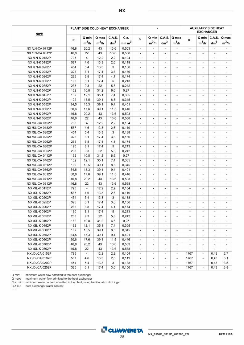
NX16. HYDRAULIC DATA
Water flow and pressure dropWater flow in the heat exchangers is given by: Q=Px0,86/DtQ: water flow (m3/h)Dt: difference between inlet and outlet water temp. (°C)P: heat exchanger capacity (kW)
Pressure drop is given by: Dp= K x Q2/1000Q: water flow (m3/h)Dp: pressure drop (kPa)K: unit size ratio
Q min: minimum water flow admitted to the heat exchangerQ max: maximum water flow admitted to the heat exchangerC.a. min: minimum water content admitted in the plant, using traditional control logicC.A.S.: heat exchanger water content- - -
AUXILIARY SIDE HEAT EXCHANGER
Q max
m³/h
Q min
m³/hK
-
Q max
m³/h
Q min
m³/hK
SIZE
PLANT SIDE COLD HEAT EXCHANGER
C.a.
min m³Q max
m³/h
Q min
m³/hK
C.A.S.
dm³C.A.S.
dm³C.A.S.
dm³795 4 12,2 0,104 - - - - - -NX /CA 0152P 2,2 - -587 4,6 13,3 0,119 - - - - - -NX /CA 0182P 2,6 - -454 5,4 13,3 0,138 - - - - - -NX /CA 0202P 3 - -325 6,1 17,4 0,156 - - - - - -NX /CA 0252P 3,6 - -265 6,8 17,4 0,174 - - - - - -NX /CA 0262P 4,1 - -190 8,1 17,4 0,213 - - - - - -NX /CA 0302P 5 - -233 9,3 22 0,242 - - - - - -NX /CA 0352P 5,8 - -162 10,8 31,2 0,27 - - - - - -NX /CA 0402P 6,6 - -132 12,1 35,1 0,305 - - - - - -NX /CA 0452P 7,4 - -102 13,5 39,1 0,345 - - - - - -NX /CA 0502P 8,5 - -84,5 15,3 39,1 0,401 - - - - - -NX /CA 0562P 9,4 - -60,6 17,6 39,1 0,446 - - - - - -NX /CA 0612P 11,5 - -46,8 20,2 43 0,503 - - - - - -NX /CA 0712P 13,6 - -46,8 22 43 0,568 - - - - - -NX /CA 0812P 13,6 - -795 4 12,2 0,104 - - - - - -NX /K 0152P 2,16 - -587 4,6 13,3 0,119 - - - - - -NX /K 0182P 2,56 - -454 5,4 13,3 0,138 - - - - - -NX /K 0202P 2,96 - -325 6,1 17,4 0,156 - - - - - -NX /K 0252P 3,6 - -265 6,8 17,4 0,174 - - - - - -NX /K 0262P 4,05 - -190 8,1 17,4 0,213 - - - - - -NX /K 0302P 4,95 - -233 9,3 22 0,242 - - - - - -NX /K 0352P 5,77 - -162 10,8 31,2 0,27 - - - - - -NX /K 0402P 6,56 - -132 12,1 35,1 0,305 - - - - - -NX /K 0452P 7,36 - -102 13,5 39,1 0,345 - - - - - -NX /K 0502P 8,48 - -84,5 15,3 39,1 0,401 - - - - - -NX /K 0552P 9,44 - -60,6 17,6 39,1 0,446 - - - - - -NX /K 0602P 11,52 - -46,8 20,2 43 0,503 - - - - - -NX /K 0702P 13,6 - -46,8 22 43 0,568 - - - - - -NX /K 0802P 13,6 - -795 4 12,2 0,104 - - - - - -NX /LN-CA 0152P 2,2 - -587 4,6 13,3 0,119 - - - - - -NX /LN-CA 0182P 2,6 - -454 5,4 13,3 0,138 - - - - - -NX /LN-CA 0202P 3 - -325 6,1 17,4 0,156 - - - - - -NX /LN-CA 0252P 3,6 - -265 6,8 17,4 0,174 - - - - - -NX /LN-CA 0262P 4,1 - -190 8,1 17,4 0,213 - - - - - -NX /LN-CA 0302P 5 - -233 9,3 22 0,242 - - - - - -NX /LN-CA 0352P 5,8 - -162 10,8 31,2 0,27 - - - - - -NX /LN-CA 0402P 6,6 - -132 12,1 35,1 0,305 - - - - - -NX /LN-CA 0452P 7,4 - -102 13,5 39,1 0,345 - - - - - -NX /LN-CA 0502P 8,5 - -84,5 15,3 39,1 0,401 - - - - - -NX /LN-CA 0562P 9,4 - -60,6 17,6 39,1 0,446 - - - - - -NX /LN-CA 0612P 11,5 - -
Q
28NX_0152P_0812P_201205_EN HFC 410A
NX
Q min: minimum water flow admitted to the heat exchangerQ max: maximum water flow admitted to the heat exchangerC.a. min: minimum water content admitted in the plant, using traditional control logicC.A.S.: heat exchanger water content- - -
AUXILIARY SIDE HEAT EXCHANGER
Q max
m³/h
Q min
m³/hK
-
Q max
m³/h
Q min
m³/hK
SIZE
PLANT SIDE COLD HEAT EXCHANGER
C.a.
min m³Q max
m³/h
Q min
m³/hK
C.A.S.
dm³C.A.S.
dm³C.A.S.
dm³46,8 20,2 43 0,503 - - - - - -NX /LN-CA 0712P 13,6 - -46,8 22 43 0,568 - - - - - -NX /LN-CA 0812P 13,6 - -795 4 12,2 0,104 - - - - - -NX /LN-K 0152P 2,2 - -587 4,6 13,3 0,119 - - - - - -NX /LN-K 0182P 2,6 - -454 5,4 13,3 0,138 - - - - - -NX /LN-K 0202P 3 - -325 6,1 17,4 0,156 - - - - - -NX /LN-K 0252P 3,6 - -265 6,8 17,4 0,174 - - - - - -NX /LN-K 0262P 4,1 - -190 8,1 17,4 0,213 - - - - - -NX /LN-K 0302P 5 - -233 9,3 22 0,242 - - - - - -NX /LN-K 0352P 5,8 - -162 10,8 31,2 0,27 - - - - - -NX /LN-K 0402P 6,6 - -132 12,1 35,1 0,305 - - - - - -NX /LN-K 0452P 7,4 - -102 13,5 39,1 0,345 - - - - - -NX /LN-K 0502P 8,5 - -84,5 15,3 39,1 0,401 - - - - - -NX /LN-K 0552P 9,4 - -60,6 17,6 39,1 0,446 - - - - - -NX /LN-K 0602P 11,5 - -46,8 20,2 43 0,503 - - - - - -NX /LN-K 0702P 13,6 - -46,8 22 43 0,568 - - - - - -NX /LN-K 0802P 13,6 - -795 4 12,2 0,104 - - - - - -NX /SL-CA 0152P 2,2 - -587 4,6 13,3 0,119 - - - - - -NX /SL-CA 0182P 2,6 - -454 5,4 13,3 0,138 - - - - - -NX /SL-CA 0202P 3 - -325 6,1 17,4 0,156 - - - - - -NX /SL-CA 0252P 3,6 - -265 6,8 17,4 0,174 - - - - - -NX /SL-CA 0262P 4,1 - -190 8,1 17,4 0,213 - - - - - -NX /SL-CA 0302P 5 - -233 9,3 22 0,242 - - - - - -NX /SL-CA 0352P 5,8 - -162 10,8 31,2 0,27 - - - - - -NX /SL-CA 0412P 6,6 - -132 12,1 35,1 0,305 - - - - - -NX /SL-CA 0462P 7,4 - -102 13,5 39,1 0,345 - - - - - -NX /SL-CA 0512P 8,5 - -84,5 15,3 39,1 0,401 - - - - - -NX /SL-CA 0562P 9,4 - -60,6 17,6 39,1 0,446 - - - - - -NX /SL-CA 0612P 11,5 - -46,8 20,2 43 0,503 - - - - - -NX /SL-CA 0712P 13,6 - -46,8 22 43 0,568 - - - - - -NX /SL-CA 0812P 13,6 - -795 4 12,2 0,104 - - - - - -NX /SL-K 0152P 2,2 - -587 4,6 13,3 0,119 - - - - - -NX /SL-K 0182P 2,6 - -454 5,4 13,3 0,138 - - - - - -NX /SL-K 0202P 3 - -325 6,1 17,4 0,156 - - - - - -NX /SL-K 0252P 3,6 - -265 6,8 17,4 0,174 - - - - - -NX /SL-K 0262P 4,1 - -190 8,1 17,4 0,213 - - - - - -NX /SL-K 0302P 5 - -233 9,3 22 0,242 - - - - - -NX /SL-K 0352P 5,8 - -162 10,8 31,2 0,27 - - - - - -NX /SL-K 0402P 6,6 - -132 12,1 35,1 0,305 - - - - - -NX /SL-K 0452P 7,4 - -102 13,5 39,1 0,345 - - - - - -NX /SL-K 0502P 8,5 - -84,5 15,3 39,1 0,401 - - - - - -NX /SL-K 0552P 9,4 - -60,6 17,6 39,1 0,446 - - - - - -NX /SL-K 0602P 11,5 - -46,8 20,2 43 0,503 - - - - - -NX /SL-K 0702P 13,6 - -46,8 22 43 0,568 - - - - - -NX /SL-K 0802P 13,6 - -795 4 12,2 0,104 - - - 1767 - 2,7NX /D /CA 0152P 2,2 - 0,43587 4,6 13,3 0,119 - - - 1767 - 3,1NX /D /CA 0182P 2,6 - 0,43454 5,4 13,3 0,138 - - - 1767 - 3,5NX /D /CA 0202P 3 - 0,43325 6,1 17,4 0,156 - - - 1767 - 3,8NX /D /CA 0252P 3,6 - 0,43
Q

NX_0152P_0812P_201205_EN HFC 410A29
NX
Q min: minimum water flow admitted to the heat exchangerQ max: maximum water flow admitted to the heat exchangerC.a. min: minimum water content admitted in the plant, using traditional control logicC.A.S.: heat exchanger water content- - -
AUXILIARY SIDE HEAT EXCHANGER
Q max
m³/h
Q min
m³/hK
-
Q max
m³/h
Q min
m³/hK
SIZE
PLANT SIDE COLD HEAT EXCHANGER
C.a.
min m³Q max
m³/h
Q min
m³/hK
C.A.S.
dm³C.A.S.
dm³C.A.S.
dm³265 6,8 17,4 0,174 - - - 1767 - 4,3NX /D /CA 0262P 4,1 - 0,43190 8,1 17,4 0,213 - - - 871 - 5,2NX /D /CA 0302P 5 - 0,61233 9,3 22 0,242 - - - 871 - 5,7NX /D /CA 0352P 5,8 - 0,61162 10,8 31,2 0,27 - - - 871 - 6,6NX /D /CA 0402P 6,6 - 0,61132 12,1 35,1 0,305 - - - 613 - 7,3NX /D /CA 0452P 7,4 - 0,73102 13,5 39,1 0,345 - - - 613 - 8,3NX /D /CA 0502P 8,5 - 0,7384,5 15,3 39,1 0,401 - - - 412 - 9,7NX /D /CA 0562P 9,4 - 0,9260,6 17,6 39,1 0,446 - - - 412 - 11,5NX /D /CA 0612P 11,5 - 0,9246,8 20,2 43 0,503 - - - 277 - 13,4NX /D /CA 0712P 13,6 - 1,2246,8 22 43 0,568 - - - 277 - 15,7NX /D /CA 0812P 13,6 - 1,22795 4 12,2 0,104 - - - 1767 - 2,7NX /D /K 0152P 2,16 - 0,43587 4,6 13,3 0,119 - - - 1767 - 3,1NX /D /K 0182P 2,56 - 0,43454 5,4 13,3 0,138 - - - 1767 - 3,5NX /D /K 0202P 2,96 - 0,43325 6,1 17,4 0,156 - - - 1767 - 3,8NX /D /K 0252P 3,6 - 0,43265 6,8 17,4 0,174 - - - 1767 - 4,3NX /D /K 0262P 4,05 - 0,43190 8,1 17,4 0,213 - - - 871 - 5,2NX /D /K 0302P 4,95 - 0,61233 9,3 22 0,242 - - - 871 - 5,7NX /D /K 0352P 5,77 - 0,61162 10,8 31,2 0,27 - - - 871 - 6,6NX /D /K 0402P 6,56 - 0,61132 12,1 35,1 0,305 - - - 613 - 7,3NX /D /K 0452P 7,36 - 0,73102 13,5 39,1 0,345 - - - 613 - 8,3NX /D /K 0502P 8,48 - 0,7384,5 15,3 39,1 0,401 - - - 412 - 9,7NX /D /K 0552P 9,44 - 0,9260,6 17,6 39,1 0,446 - - - 412 - 11,5NX /D /K 0602P 11,52 - 0,9246,8 20,2 43 0,503 - - - 277 - 13,4NX /D /K 0702P 13,6 - 1,2246,8 22 43 0,568 - - - 277 - 15,7NX /D /K 0802P 13,6 - 1,22795 4 12,2 0,104 - - - 1767 - 2,7NX /D /LN-CA 0152P 2,2 - 0,43587 4,6 13,3 0,119 - - - 1767 - 3,1NX /D /LN-CA 0182P 2,6 - 0,43454 5,4 13,3 0,138 - - - 1767 - 3,5NX /D /LN-CA 0202P 3 - 0,43325 6,1 17,4 0,156 - - - 1767 - 3,8NX /D /LN-CA 0252P 3,6 - 0,43265 6,8 17,4 0,174 - - - 1767 - 4,3NX /D /LN-CA 0262P 4,1 - 0,43190 8,1 17,4 0,213 - - - 871 - 5,2NX /D /LN-CA 0302P 5 - 0,61233 9,3 22 0,242 - - - 871 - 5,7NX /D /LN-CA 0352P 5,8 - 0,61162 10,8 31,2 0,27 - - - 871 - 6,6NX /D /LN-CA 0402P 6,6 - 0,61132 12,1 35,1 0,305 - - - 613 - 7,3NX /D /LN-CA 0452P 7,4 - 0,73102 13,5 39,1 0,345 - - - 613 - 8,3NX /D /LN-CA 0502P 8,5 - 0,7384,5 15,3 39,1 0,401 - - - 412 - 9,7NX /D /LN-CA 0562P 9,4 - 0,9260,6 17,6 39,1 0,446 - - - 412 - 11,5NX /D /LN-CA 0612P 11,5 - 0,9246,8 20,2 43 0,503 - - - 277 - 13,4NX /D /LN-CA 0712P 13,6 - 1,2246,8 22 43 0,568 - - - 277 - 15,7NX /D /LN-CA 0812P 13,6 - 1,22795 4 12,2 0,104 - - - 1767 - 2,7NX /D /LN-K 0152P 2,2 - 0,43587 4,6 13,3 0,119 - - - 1767 - 3,1NX /D /LN-K 0182P 2,6 - 0,43454 5,4 13,3 0,138 - - - 1767 - 3,5NX /D /LN-K 0202P 3 - 0,43325 6,1 17,4 0,156 - - - 1767 - 3,8NX /D /LN-K 0252P 3,6 - 0,43265 6,8 17,4 0,174 - - - 1767 - 4,3NX /D /LN-K 0262P 4,1 - 0,43190 8,1 17,4 0,213 - - - 871 - 5,2NX /D /LN-K 0302P 5 - 0,61233 9,3 22 0,242 - - - 871 - 5,7NX /D /LN-K 0352P 5,8 - 0,61162 10,8 31,2 0,27 - - - 871 - 6,6NX /D /LN-K 0402P 6,6 - 0,61132 12,1 35,1 0,305 - - - 613 - 7,3NX /D /LN-K 0452P 7,4 - 0,73102 13,5 39,1 0,345 - - - 613 - 8,3NX /D /LN-K 0502P 8,5 - 0,73
Q

30NX_0152P_0812P_201205_EN HFC 410A
NX
Q min: minimum water flow admitted to the heat exchangerQ max: maximum water flow admitted to the heat exchangerC.a. min: minimum water content admitted in the plant, using traditional control logicC.A.S.: heat exchanger water content- - -
AUXILIARY SIDE HEAT EXCHANGER
Q max
m³/h
Q min
m³/hK
-
Q max
m³/h
Q min
m³/hK
SIZE
PLANT SIDE COLD HEAT EXCHANGER
C.a.
min m³Q max
m³/h
Q min
m³/hK
C.A.S.
dm³C.A.S.
dm³C.A.S.
dm³84,5 15,3 39,1 0,401 - - - 412 - 9,7NX /D /LN-K 0552P 9,4 - 0,9260,6 17,6 39,1 0,446 - - - 412 - 11,5NX /D /LN-K 0602P 11,5 - 0,9246,8 20,2 43 0,503 - - - 277 - 13,4NX /D /LN-K 0702P 13,6 - 1,2246,8 22 43 0,568 - - - 277 - 15,7NX /D /LN-K 0802P 13,6 - 1,22795 4 12,2 0,104 - - - 1767 - 2,7NX /D /SL-CA 0152P 2,2 - 0,43587 4,6 13,3 0,119 - - - 1767 - 3,1NX /D /SL-CA 0182P 2,6 - 0,43454 5,4 13,3 0,138 - - - 1767 - 3,5NX /D /SL-CA 0202P 3 - 0,43325 6,1 17,4 0,156 - - - 1767 - 3,8NX /D /SL-CA 0252P 3,6 - 0,43265 6,8 17,4 0,174 - - - 1767 - 4,3NX /D /SL-CA 0262P 4,1 - 0,43190 8,1 17,4 0,213 - - - 871 - 5,2NX /D /SL-CA 0302P 5 - 0,61233 9,3 22 0,242 - - - 871 - 5,7NX /D /SL-CA 0352P 5,8 - 0,61162 10,8 31,2 0,27 - - - 871 - 6,6NX /D /SL-CA 0412P 6,6 - 0,61132 12,1 35,1 0,305 - - - 613 - 7,3NX /D /SL-CA 0462P 7,4 - 0,73102 13,5 39,1 0,345 - - - 613 - 8,3NX /D /SL-CA 0512P 8,5 - 0,7384,5 15,3 39,1 0,401 - - - 412 - 9,7NX /D /SL-CA 0562P 9,4 - 0,9260,6 17,6 39,1 0,446 - - - 412 - 11,5NX /D /SL-CA 0612P 11,5 - 0,9246,8 20,2 43 0,503 - - - 277 - 13,4NX /D /SL-CA 0712P 13,6 - 1,2246,8 22 43 0,568 - - - 277 - 15,7NX /D /SL-CA 0812P 13,6 - 1,22795 4 12,2 0,104 - - - 1767 - 2,7NX /D /SL-K 0152P 2,2 - 0,43587 4,6 13,3 0,119 - - - 1767 - 3,1NX /D /SL-K 0182P 2,6 - 0,43454 5,4 13,3 0,138 - - - 1767 - 3,5NX /D /SL-K 0202P 3 - 0,43325 6,1 17,4 0,156 - - - 1767 - 3,8NX /D /SL-K 0252P 3,6 - 0,43265 6,8 17,4 0,174 - - - 1767 - 4,3NX /D /SL-K 0262P 4,1 - 0,43190 8,1 17,4 0,213 - - - 871 - 5,2NX /D /SL-K 0302P 5 - 0,61233 9,3 22 0,242 - - - 871 - 5,7NX /D /SL-K 0352P 5,8 - 0,61162 10,8 31,2 0,27 - - - 871 - 6,6NX /D /SL-K 0402P 6,6 - 0,61132 12,1 35,1 0,305 - - - 613 - 7,3NX /D /SL-K 0452P 7,4 - 0,73102 13,5 39,1 0,345 - - - 613 - 8,3NX /D /SL-K 0502P 8,5 - 0,7384,5 15,3 39,1 0,401 - - - 412 - 9,7NX /D /SL-K 0552P 9,4 - 0,9260,6 17,6 39,1 0,446 - - - 412 - 11,5NX /D /SL-K 0602P 11,5 - 0,9246,8 20,2 43 0,503 - - - 277 - 13,4NX /D /SL-K 0702P 13,6 - 1,2246,8 22 43 0,568 - - - 277 - 15,7NX /D /SL-K 0802P 13,6 - 1,22
Q

NX_0152P_0812P_201205_EN HFC 410A31
NX17. HYDRONIC GROUP (Optional)
The units can be supplied with a hydronic group. This includesall the main hydraulic components, thereby optimising hydraulicand electric installation space, time and cost.
Storage tank combinations
“LONGITUDINAL V-SHAPED” STRUCTURE UNIT
Available pump confi gurations:- Hydronic kit with one 2-pole low-head pump- Hydronic kit with one 2-pole high-head pump- Hydronic kit with two 2-pole low-head pumps- Hydronic kit with two 2-pole high-head pumps
Storage tank (upon request)The storage tank system features:- 90 to 250 litres tank for the sizes and versions shown in thetable of combinations,
- expansion vessel (EPDM membrane), with 1.5 bar pre-char-ge,
- pressure gauge,- safety valve calibrated to 6 bars,- storage tank with 20 mm lining,- tank frost protection heater upon request.
2-pole low-head pumpHorizontal one-piece centrifuge pump with one impeller, axialsuction and radial delivery, AISI 304L stainless steel pump bodyimpeller. The section of shaft in contact with the liquid is madeof stainless steel. Mechanical seal made of components inceramics/carbon/NBR/AISI304. Three-phase electric motor pro-tected to IP55, insulation class F, suitable for continuous servi-ce.
2-pole high-head pumpAll versions of the hydronic unit can be supplied with a high-head pump. In these cases, the pump features a two-polemotor even in the silent-running versions.
Second pumpA second stand-by pump for high or low pressures is availableon request. The pumps are automatically exchanged on thebasis of a rotation program and the stand-by pump cuts in auto-matically if the primary pump fails. The two-pump hydronicassembly is also fitted with check valves to ensure the unitworks correctly
“HORIZONTAL V-SHAPED” STRUCTURE UNIT
Available pump configurations:- Hydronic kit with one IN-LINE 2-pole low-head pump- Hydronic kit with one IN-LINE 2-pole high-head pump- Hydronic kit with IN-LINE 2-pole low-head twin pumps- Hydronic kit with IN-LINE 2-pole high-head twin pumps
Storage tank (upon request)The storage tank system features:- 500 litre tank for the sizes and versions shown in the table ofcombinations,
- expansion vessel (EPDM membrane), with 1.5 bar pre-charge,- pressure gauge,- safety valve calibrated to 6 bars,- storage tank with 20 mm lining,- tank frost protection heater upon request.
2-pole low-head pumpCentrifugal pumps with in-line suction and delivery flanges, insingle and twin versions. Pump body in cast iron and impeller inAISI 316L stainless steel or cast-iron, entirely laser technologywelded. Mechanical seal with components in ceramics, carbonand EPDM elastomers. Three-phase electric motor protected toIP55, insulation class F, suitable for continuous service.
NX VERSIONWATER TANKCapacity[litre]
0152P
K90
LN-KSL-K 140CA 90
LN-CA140
SL-CA
0182P
K90
LN-KSL-K
140CA
LN-CASL-CA
0202P
K 90LN-K
140SL-KCA
LN-CASL-CA
0252P
K
140LN-KSL-KCA
LN-CASL-CA 200
0262P
K
140LN-KSL-KCA
LN-CASL-CA 200
0302P
K
140LN-KSL-KCA
LN-CA200
SL-CA
0352P
K140
LN-KSL-K
200CALN-CASL-CA 250
NX VERSIONWATER TANKCapacity[litre]
0402P
K 140LN-K
200SL-KCA
LN-CA 2500412P SL-CA 500
0452P
K 140LN-K 200SL-K 250CA 200
LN-CA 2500462P SL-CA 500
0502P
K 140LN-K 200SL-K
250CALN-CA
0512P SL-CA 500
0552PK
200LN-KSL-K 250
0562PCA
500LN-CASL-CA
0602PK
250LN-KSL-K
0612PCA
500LN-CASL-CA
0702PK
250LN-KSL-K
0712PCA
500LN-CASL-CA
0802PK
250LN-KSL-K
0812PCA
500LN-CASL-CA

32NX_0152P_0812P_201205_EN HFC 410A
NX
2-pole high-head pumpAll versions of the hydronic unit can be supplied with a highhead pump. In these cases, the pump features a two-polemotor even in the silent-running versions.
Twin pumpA second stand-by pump for high or low pressures is availableon request. The pumps are automatically exchanged on thebasis of a rotation programme and the stand-by pump cuts inautomatically if the primary pump fails.
GENERAL CHARACTERISTICSWater connectionsIn the units without pumps, standard version, the connectionsfor the water inlet and outlet both in the evaporator and in thedesuperheater are inside the unit. As an accessory one canrequest these connections fl ush with the unit.For units with pumps, the connections are always fl ush with theunit.
Water-side mechanical filter (optional)Y-filter designed and built to capture the impurities in thehydraulic circuit. It is fitted with a 0.9 mm stainless steel meshcartridge which can be replaced without removing the valvebody from the piping.
Unit electrical panelThe unit electrical panel is fitted with fuses and a circuit breakercontactor.
Special pumpsFor pumps with different configurations, please contact oursales department.
Additional componentsThe supply does not include the following accessories thoughthese are recommended to ensure correct system operation:MA Pressure gauges upline and downline from the unitGF Flexible joints on pipingRI On-off valvesT Outlet control thermometer

NX_0152P_0812P_201205_EN HFC 410A33
NXHYDRONIC GROUP (Optional)
17.1 Hydraulic diagram
P
S1
S2
EV
SF
SC
Pd
P
Sonda ingresso acqua scambiatore Exchanger water inlet probe
P
LEGENDA - LEGEND
SC
S1
S2 Sonda uscita acqua scambiatoreExchanger water outlet probe
EV
Drain valveValvola di scarico
EvaporatorEvaporatore
PompaWater pump
RITORNO DALL'IMPIANTORETURN FROM HYDRAULIC SYSTEM
MANDATA ALL'IMPIANTODISCHARGE TO HYDRAULIC SYSTEM
SF Purge valveValvola di sfiato
CONPONENTI DEL KIT IDRONICOCOMPONENTS OF THE HYDRONIC KIT
Pd Water Differential pressure switchPressostato differenziale lato acqua

34NX_0152P_0812P_201205_EN HFC 410A
NX
17.2 Hydraulic diagram with water tank
Pd
S1
S2
Sc1
EV
~VE
Sc2VA
Sf2
AC
P P
RRMA
Sf1
Sc1
Evaporators/Condensers water outlet probe
Evaporators/Condensers water inlet probeSonda uscita acqua evaporatori/condensatori
Sonda ingresso acqua evaporatori/condensatori
Pressostato differenzialeDifferential pressure switch
Evaporatore
S2
S1
Pd
LEGENDA - LEGEND
EV Evaporator
Scarico Evaporatore/CondensatoreEvaporator/Condenser drain valve
DISCHARGE TO HYDRAULIC SYSTEM
Sc1
MANDATA ALL'IMPIANTO
Evaporator/Condenser breather valveSfiato Evaporatore/CondensatoreSf1
RITORNO DALL'IMPIANTORETURN FROM HYDRAULIC SYSTEM
AccumuloWater tankAC
MA Water pressure gaugeManometro
P PompaWater pump
Filling valveRubinetto reintegroRR
Sc2 Water tank drain valveScarico acqua accumulo
Sfiato accumuloTank breather valveSf2
Safety valveValvola di sicurezzaVA
VE Vaso di espansioneExpansion tank
HYDRONIC GROUP (Optional)

SIZE VERSIONPf (1) Q (1) Rif.
PumpTypePump
N. Poles
F.L.I. F.L.A.Ks
Dps HuKfi
[kW] [m3/h] [kW] [A] [kPa] [kPa]
0152P
K 39,2 6,75
A1 DWC-V 300/1.1(R)* 2 1,1 3,2 855,9
39 98
130,0
SL-K 39,3 6,76 39 97
LN-K 39,4 6,78 39 97
CA 41,6 7,16 44 91
LN-CA 41,5 7,14 44 92
SL-CA 41,9 7,21 44 91
0182P
K 44,3 7,62
A2
DWC-V 300/1.1(R) 2 1,1 3,2
647,9
38 96
SL-K 44,3 7,62 38 96
LN-K 44,6 7,67 38 95
CA 47,4 8,15 43 89
LN-CA 47,0 8,08 42 90
SL-CA 47,5 8,17 43 88
0202P
K 51,9 8,93
A3 514,9
41 87
SL-K 51,7 8,89 41 88
LN-K 52,3 9,00 42 87
CA 55,0 9,46 46 80
LN-CA 54,9 9,44 46 80
SL-CA 55,3 9,51 47 79
0252P
K 58,9 10,13
A4 386,0
40 84
SL-K 58,8 10,11 39 84
LN-K 58,9 10,13 40 84
CA 62,5 10,75 45 76
LN-CA 63,5 10,92 46 73
SL-CA 62,2 10,70 44 76
0262P
K 65,1 11,19
B1
DWC-V 300/1.1 2 1,1 3,2
326,0
41 133
130,0
SL-K 65,5 11,27 41 132
LN-K 65,9 11,33 42 131
CA 69,6 11,97 47 123
LN-CA 70,7 12,16 48 121
SL-CA 69,2 11,90 46 124
0302P
K 77,6 13,35
B2 251,0
45 118
78,5
SL-K 74,7 12,85 41 124
LN-K 77,7 13,36 45 118
CA 85,2 14,65 54 102
LN-CA 82,7 14,22 51 107
SL-CA 81,9 14,09 50 109
0352P
K 88,4 15,21
C1
DWC-V 300/1.5 2 1,5 3,7
294,5
68 124
78,5
SL-K 90,0 15,48 71 120
LN-K 88,5 15,22 68 124
CA 96,6 16,62 81 103
LN-CA 94,4 16,24 78 109
SL-CA 94,4 16,24 78 109
0402P
K 102,0 17,55
C2 176,6
54 125
47,9
LN-K 99,4 17,10 52 130
SL-K 100,0 17,20 52 129
CA 108,0 18,58 61 113
LN-CA 107,5 18,49 60 114
0452P
K 114,5 19,70
C3 146,6
57 110
LN-K 112,9 19,42 55 114
SL-K 113,4 19,50 56 113
CA 121,9 20,97 64 95
LN-CA 120,6 20,74 63 98
(1) Values refer to rated operating conditions Pf Cooling capacity of unit Pt Heating capacity of unit Q Flow of water to evaporator F.L.I. Power absorbed by pump F.L.A. Current absorbed by pump
Ks Coeffi cients for calculating pressure drops Unit with hydronic unit without network fi lter and 3 way valve Kfi Coeffi cients fi lter for calculating pressure dropsDps Total pressure drop of hydronic group Hu Residual head
1 PUMP - LOW HEAD PUMP WITH OR WITHOUT WATER TANK (Longitudinal V-shaped coil module)
35 NX_0152P_0812P_201204_EN HFC R410A
NX

WORKING HEAD CURVES
0102030405060708090
100110120130140150160170180190200210220230
5 6 7 8 9 10 11 12 13 14 15 16 17 18 19 20 21 22 23 24 25
Hu
[kPa
]
Q [m3/h]
A1 A2B1 B2 C1
C2A3 A4
C3
36 NX_0152P_0812P_201204_EN
NX
HFC R410A

SIZE VERSIONPf (1) Q (1) Rif.
PumpTypePump
N. Poles
F.L.I. F.L.A.Ks
Dps HuKfi
[kW] [m3/h] [kW] [A] [kPa] [kPa]
0502P
K 127,4 21,91
D1
DWC-V 500/1,5 2 1,5 3,7
116,6
56 91
23,7
LN-K 125,2 21,53 54 94
SL-K 124,4 21,40 53 95
CA 137,8 23,69 65 76
LN-CA 134,0 23,05 62 81
0552PK 144,2 24,80
D2 99,1
61 77
LN-K 139,9 24,06 57 83
SL-K 140,5 24,17 58 82
0602PK 165,6 28,49
E1 DWC-V 500/2.2 2 2,2 4,5 75,4
61 130
23,7LN-K 162,8 28,00 59 134
SL-K 153,0 26,32 52 146
0702PK 189,4 32,58
F1 DWC-V 500/3 2 3 6,1 61,6
65 124
23,7LN-K 179,4 30,86 59 137
SL-K 175,4 30,17 56 142
0802PK 206,6 35,54 78 101
4,9LN-K 194,0 33,37 69 118
SL-K 189,1 32,53 65 125
WORKING HEAD CURVES
0102030405060708090
100110120130140150160170180190200210220230240
11 12 13 14 15 16 17 18 19 20 21 22 23 24 25 26 27 28 29 30 31 32 33 34 35 36 37 38 39 40 41 42 43 44 45 46
Hu
[kPa
]
Q [m3/h]
D1 D2 E1F1
(1) Values refer to rated operating conditions Pf Cooling capacity of unit Pt Heating capacity of unit Q Flow of water to evaporator F.L.I. Power absorbed by pump F.L.A. Current absorbed by pump
Ks Coeffi cients for calculating pressure drops Unit with hydronic unit without network fi lter and 3 way valve Kfi Coeffi cients fi lter for calculating pressure dropsDps Total pressure drop of hydronic group Hu Residual head
37 NX_0152P_0812P_201204_EN HFC R410A
NX

2 PUMPS - LOW HEAD PUMP WITH OR WITHOUT WATER TANK (Longitudinal V-shaped coil module)
SIZE VERSIONPf (1) Q (1) Rif.
PumpTypePump
N. Poles
F.L.I. F.L.A.Ks
Dps HuKfi
[kW] [m3/h] [kW] [A] [kPa] [kPa]
0152P
K 39,2 6,75
A1 DWC-V 300/1.1(R)* 2 1,1 3,2 898,5
41 96
130
SL-K 39,3 6,76 41 96
LN-K 39,4 6,78 41 95
CA 41,6 7,16 46 89
LN-CA 41,5 7,14 46 90
SL-CA 41,9 7,21 47 88
0182P
K 44,3 7,62
A2
DWC-V 300/1.1(R) 2 1,1 3,2
690,5
40 94
SL-K 44,3 7,62 40 94
LN-K 44,6 7,67 41 93
CA 47,4 8,15 46 86
LN-CA 47,0 8,08 45 87
SL-CA 47,5 8,17 46 85
0202P
K 51,9 8,93
A3 557,5
44 84
SL-K 51,7 8,89 44 85
LN-K 52,3 9,00 45 83
CA 55,0 9,46 50 76
LN-CA 54,9 9,44 50 77
SL-CA 55,3 9,51 50 76
0252P
K 58,9 10,13
A4 426,9
44 79
SL-K 58,8 10,11 44 80
LN-K 58,9 10,13 44 79
CA 62,5 10,75 49 71
LN-CA 63,5 10,92 51 69
SL-CA 62,2 10,70 49 72
0262P
K 65,1 11,19
B1
DWC-V 300/1.1 2 1,1 3,2
366,9
46 128
130,0
SL-K 65,5 11,27 47 127
LN-K 65,9 11,33 47 126
CA 69,6 11,97 53 118
LN-CA 70,7 12,16 54 115
SL-CA 69,2 11,90 52 119
0302P
K 77,6 13,35
B2 291,9
52 111
78,5
SL-K 74,7 12,85 48 118
LN-K 77,7 13,36 52 111
CA 85,2 14,65 63 93
LN-CA 82,7 14,22 59 99
SL-CA 81,9 14,09 58 101
0352P
K 88,4 15,21
C1
DWC-V 300/1.5 2 1,5 3,7
334,9
77 115
78,5
SL-K 90,0 15,48 80 111
LN-K 88,5 15,22 78 115
CA 96,6 16,62 92 92
LN-CA 94,4 16,24 88 99
SL-CA 94,4 16,24 88 99
0402P
K 102,0 17,55
C2 192,6
59 120
47,9
LN-K 99,4 17,10 56 126
SL-K 100,0 17,20 57 125
CA 108,0 18,58 66 107
LN-CA 107,5 18,49 66 108
0452P
K 114,5 19,70
C3 162,6
63 104
LN-K 112,9 19,42 61 108
SL-K 113,4 19,50 62 106
CA 121,9 20,97 71 88
LN-CA 120,6 20,74 70 91
(1) Values refer to rated operating conditions Pf Cooling capacity of unit Pt Heating capacity of unit Q Flow of water to evaporator F.L.I. Power absorbed by pump F.L.A. Current absorbed by pump
Ks Coeffi cients for calculating pressure drops Unit with hydronic unit without network fi lter and 3 way valve Kfi Coeffi cients fi lter for calculating pressure dropsDps Total pressure drop of hydronic group Hu Residual head
38 NX_0152P_0812P_201204_EN
NX
HFC R410A

WORKING HEAD CURVES
0102030405060708090
100110120130140150160170180190200210220230
5 6 7 8 9 10 11 12 13 14 15 16 17 18 19 20 21 22 23 24 25
Hu
[kPa
]
Q [m3/h]
A1 A2B1 B2 C1
C2A3 A4
C3
39 NX_0152P_0812P_201204_EN HFC R410A
NX

SIZE VERSIONPf (1) Q (1) Rif.
PumpTypePump
N. Poles
F.L.I. F.L.A.Ks
Dps HuKfi
[kW] [m3/h] [kW] [A] [kPa] [kPa]
0502P
K 127,4 21,91
D1
DWC-V 500/1,5 2 1,5 3,7
132,6
64 83
23,7
LN-K 125,2 21,53 61 86
SL-K 124,4 21,40 61 87
CA 137,8 23,69 74 67
LN-CA 134,0 23,05 70 73
0552PK 144,2 24,80
D2 115,1
71 67
LN-K 139,9 24,06 67 73
SL-K 140,5 24,17 67 73
0602PK 165,6 28,49
E1 DWC-V 500/2.2 2 2,2 4,5 91,2
74 117
23,7LN-K 162,8 28,00 72 121
SL-K 153,0 26,32 63 135
0702PK 189,4 32,58
F1 DWC-V 500/3 2 3 6,1 77,4
82 108
23,7LN-K 179,4 30,86 74 122
SL-K 175,4 30,17 70 128
0802PK 206,6 35,54 98 81
4,9LN-K 194,0 33,37 86 101
SL-K 189,1 32,53 82 108
WORKING HEAD CURVES
0102030405060708090
100110120130140150160170180190200210220230240
11 12 13 14 15 16 17 18 19 20 21 22 23 24 25 26 27 28 29 30 31 32 33 34 35 36 37 38 39 40 41 42 43 44
Hu
[kPa
]
Q [m3/h]
D1 D2 E1 F1
(1) Values refer to rated operating conditions Pf Cooling capacity of unit Pt Heating capacity of unit Q Flow of water to evaporator F.L.I. Power absorbed by pump F.L.A. Current absorbed by pump
Ks Coeffi cients for calculating pressure drops Unit with hydronic unit without network fi lter and 3 way valve Kfi Coeffi cients fi lter for calculating pressure dropsDps Total pressure drop of hydronic group Hu Residual head
40 NX_0152P_0812P_201204_EN
NX
HFC R410A

1 PUMP - HIGH HEAD PUMP WITH OR WITHOUT WATER TANK (Longitudinal V-shaped coil module)
SIZE VERSIONPf (1) Q (1) Rif.
PumpTypePump
N. Poles
F.L.I. F.L.A.Ks
Dps HuKfi
[kW] [m3/h] [kW] [A] [kPa] [kPa]
0152P
K 39,2 6,75
E1
DWC-V 500/2,2* 2 2,2 4,5
855,9
39 203
130
SL-K 39,3 6,76 39 202
LN-K 39,4 6,78 39 202
CA 41,6 7,16 44 196
LN-CA 41,5 7,14 44 196
SL-CA 41,9 7,21 44 196
0182P
K 44,3 7,62
E2 647,9
38 202
SL-K 44,3 7,62 38 202
LN-K 44,6 7,67 38 201
CA 47,4 8,15 43 196
LN-CA 47,0 8,08 42 196
SL-CA 47,5 8,17 43 195
0202P
K 51,9 8,93
E3 514,9
41 196
SL-K 51,7 8,89 41 197
LN-K 52,3 9,00 42 196
CA 55,0 9,46 46 190
LN-CA 54,9 9,44 46 190
SL-CA 55,3 9,51 47 190
0252P
K 58,9 10,13
F1
DWC-V 500/3 2 3 6,1
386,0
40 204
130,0
SL-K 58,8 10,11 39 204
LN-K 58,9 10,13 40 204
CA 62,5 10,75 45 199
LN-CA 63,5 10,92 46 197
SL-CA 62,2 10,70 44 199
0262P
K 65,1 11,19
F2 326,0
41 202
SL-K 65,5 11,27 41 202
LN-K 65,9 11,33 42 201
CA 69,6 11,97 47 196
LN-CA 70,7 12,16 48 194
SL-CA 69,2 11,90 46 196
0302P
K 77,6 13,35
F3 251,0
45 196
78,5
SL-K 74,7 12,85 41 200
LN-K 77,7 13,36 45 196
CA 85,2 14,65 54 185
LN-CA 82,7 14,22 51 189
SL-CA 81,9 14,09 50 190
(1) Values refer to rated operating conditions Pf Cooling capacity of unit Pt Heating capacity of unit Q Flow of water to evaporator F.L.I. Power absorbed by pump F.L.A. Current absorbed by pump
Ks Coeffi cients for calculating pressure drops Unit with hydronic unit without network fi lter and 3 way valve Kfi Coeffi cients fi lter for calculating pressure dropsDps Total pressure drop of hydronic group Hu Residual head
41 NX_0152P_0812P_201204_EN HFC R410A
NX

0102030405060708090
100110120130140150160170180190200210220230
5 6 7 8 9 10 11 12 13 14 15 16 17 18 19 20 21 22 23 24 25 26 27
Hu
[kPa
]
Q [m3/h]
E1 E2 E3 F1 F2 F3
WORKING HEAD CURVES
42 NX_0152P_0812P_201204_EN
NX
HFC R410A

SIZE VERSIONPf (1) Q (1) Rif.
PumpTypePump
N. Poles
F.L.I. F.L.A.Ks
Dps HuKfi
[kW] [m3/h] [kW] [A] [kPa] [kPa]
0352P
K 88,4 15,21
G1
FHE 32-160/22** 2 2,2 4,64
294,5
68 205
78,5
SL-K 90,0 15,48 71 199
LN-K 88,5 15,22 68 204
CA 96,6 16,62 81 179
LN-CA 94,4 16,24 78 187
SL-CA 94,4 16,24 78 187
0402P
K 102,0 17,55
G2 176,6
54 199
47,9
LN-K 99,4 17,10 52 203
SL-K 100,0 17,20 52 203
CA 108,0 18,58 61 182
LN-CA 107,5 18,49 60 183
0452P
K 114,5 19,70
H1
FHE 40-160/30 2 3 6,14
146,6
59 224
LN-K 112,9 19,42 57 227
SL-K 113,4 19,50 58 226
CA 121,9 20,97 67 212
LN-CA 120,6 20,74 65 214
0502P
K 127,4 21,91
H2 116,6
59 217
23,7
LN-K 125,2 21,53 57 220
SL-K 124,4 21,40 56 222
CA 137,8 23,69 68 201
LN-CA 134,0 23,05 65 207
0552PK 144,2 24,80
H3 99,1
64 201
LN-K 139,9 24,06 61 207
SL-K 140,5 24,17 61 206
0602PK 165,6 28,49
H4 75,4
66 184
23,7LN-K 162,8 28,00 63 188
SL-K 153,0 26,32 56 203
0702PK 189,4 32,58
I1 FHE 40-160/40 2 4 7,63 61,6
71 226
23,7LN-K 179,4 30,86 64 242
SL-K 175,4 30,17 61 248
0802PK 206,6 35,54 85 196
4,9LN-K 194,0 33,37 75 218
SL-K 189,1 32,53 71 226
(1) Values refer to rated operating conditions Pf Cooling capacity of unit Pt Heating capacity of unit Q Flow of water to evaporator F.L.I. Power absorbed by pump F.L.A. Current absorbed by pump
Ks Coeffi cients for calculating pressure drops Unit with hydronic unit without network fi lter and 3 way valve Kfi Coeffi cients fi lter for calculating pressure dropsDps Total pressure drop of hydronic group Hu Residual head
43 NX_0152P_0812P_201204_EN HFC R410A
NX

WORKING HEAD CURVES
020406080
100120140160180200220240260280300320340
8 10 12 14 16 18 20 22 24 26 28 30 32 34 36 38 40 42 44 46 48 50
Hu
[kPa
]
Q [m3/h]
G1 G2H1 H2 H3 H4
I1
44 NX_0152P_0812P_201204_EN
NX
HFC R410A

2 PUMPS - HIGH HEAD PUMP WITH OR WITHOUT WATER TANK (Longitudinal V-shaped coil module)
SIZE VERSIONPf (1) Q (1) Rif.
PumpTypePump
N. Poles
F.L.I. F.L.A.Ks
Dps HuKfi
[kW] [m3/h] [kW] [A] [kPa] [kPa]
0152P
K 39,2 6,75
E1
DWC-V 500/2,2* 2 2,2 4,5
898,5
41 201
130
SL-K 39,3 6,76 41 200
LN-K 39,4 6,78 41 200
CA 41,6 7,16 46 194
LN-CA 41,5 7,14 46 194
SL-CA 41,9 7,21 47 194
0182P
K 44,3 7,62
E2 690,5
40 199
SL-K 44,3 7,62 40 199
LN-K 44,6 7,67 41 198
CA 47,4 8,15 46 193
LN-CA 47,0 8,08 45 193
SL-CA 47,5 8,17 46 192
0202P
K 51,9 8,93
E3 557,5
44 193
SL-K 51,7 8,89 44 193
LN-K 52,3 9,00 45 192
CA 55,0 9,46 50 186
LN-CA 54,9 9,44 50 187
SL-CA 55,3 9,51 50 186
0252P
K 58,9 10,13
F1
DWC-V 500/3 2 3 6,1
426,9
44 200
130,0
SL-K 58,8 10,11 44 200
LN-K 58,9 10,13 44 200
CA 62,5 10,75 49 194
LN-CA 63,5 10,92 51 192
SL-CA 62,2 10,70 49 195
0262P
K 65,1 11,19
F2 366,9
46 197
SL-K 65,5 11,27 47 196
LN-K 65,9 11,33 47 196
CA 69,6 11,97 53 190
LN-CA 70,7 12,16 54 188
SL-CA 69,2 11,90 52 190
0302P
K 77,6 13,35
F3 291,9
52 189
78,5
SL-K 74,7 12,85 48 193
LN-K 77,7 13,36 52 189
CA 85,2 14,65 63 176
LN-CA 82,7 14,22 59 180
SL-CA 81,9 14,09 58 182
(1) Values refer to rated operating conditions Pf Cooling capacity of unit Pt Heating capacity of unit Q Flow of water to evaporator F.L.I. Power absorbed by pump F.L.A. Current absorbed by pump
Ks Coeffi cients for calculating pressure drops Unit with hydronic unit without network fi lter and 3 way valve Kfi Coeffi cients fi lter for calculating pressure dropsDps Total pressure drop of hydronic group Hu Residual head
45 NX_0152P_0812P_201204_EN HFC R410A
NX

0102030405060708090
100110120130140150160170180190200210220230
4 5 6 7 8 9 10 11 12 13 14 15 16 17 18 19 20 21 22 23 24 25 26 27 28 29
Hu
[kPa
]
Q [m3/h]
E1 E2 E3 F1 F2 F3
WORKING HEAD CURVES
46 NX_0152P_0812P_201204_EN
NX
HFC R410A

(1) Values refer to rated operating conditions Pf Cooling capacity of unit Pt Heating capacity of unit Q Flow of water to evaporator F.L.I. Power absorbed by pump F.L.A. Current absorbed by pump
Ks Coeffi cients for calculating pressure drops Unit with hydronic unit without network fi lter and 3 way valve Kfi Coeffi cients fi lter for calculating pressure dropsDps Total pressure drop of hydronic group Hu Residual head
SIZE VERSIONPf (1) Q (1) Rif.
PumpTypePump
N. Poles
F.L.I. F.L.A.Ks
Dps HuKfi
[kW] [m3/h] [kW] [A] [kPa] [kPa]
0352P
K 88,4 15,21
G1
FHE 32-160/22** 2 2,2 4,64
334,9
77 195
78,5
SL-K 90,0 15,48 80 189
LN-K 88,5 15,22 78 195
CA 96,6 16,62 92 168
LN-CA 94,4 16,24 88 177
SL-CA 94,4 16,24 88 177
0402P
K 102,0 17,55
G2 192,6
59 194
47,9
LN-K 99,4 17,10 56 199
SL-K 100,0 17,20 57 198
CA 108,0 18,58 66 177
LN-CA 107,5 18,49 66 177
0452P
K 114,5 19,70
H1
FHE 40-160/30 2 3 6,14
167,9
65 217
LN-K 112,9 19,42 63 221
SL-K 113,4 19,50 64 220
CA 121,9 20,97 74 205
LN-CA 120,6 20,74 72 207
0502P
K 127,4 21,91
H2 137,9
66 209
23,7
LN-K 125,2 21,53 64 213
SL-K 124,4 21,40 63 214
CA 137,8 23,69 77 192
LN-CA 134,0 23,05 73 198
0552PK 144,2 24,80
H3 120,5
74 191
LN-K 139,9 24,06 70 198
SL-K 140,5 24,17 70 196
0602PK 165,6 28,49
H4 96,7
78 171
23,7LN-K 162,8 28,00 76 175
SL-K 153,0 26,32 67 192
0702PK 189,4 32,58
I1 FHE 40-160/40 2 4 7,63
82,9
88 209
23,7LN-K 179,4 30,86 79 227
SL-K 175,4 30,17 75 234
0802PK 206,6 35,54
82,9
105 176
4,9LN-K 194,0 33,37 92 200
SL-K 189,1 32,53 88 210
47 NX_0152P_0812P_201204_EN HFC R410A
NX

WORKING HEAD CURVES
020406080
100120140160180200220240260280300320340
8 10 12 14 16 18 20 22 24 26 28 30 32 34 36 38 40 42 44 46 48 50
Hu
[kPa
]
Q [m3/h]
G1 G2 H1 H2 H3 H4
I1
48 NX_0152P_0812P_201204_EN
NX
HFC R410A

SIZE VERSIONPf (1) Q (1) Rif.
PumpTypePump
N. Poles
F.L.I. F.L.A.Ks
Dps HuKfi
[kW] [m3/h] [kW] [A] [kPa] [kPa]
0412P SL-CA 106,0 18,23 A1FCE 50-125/15 2 1,5 3,02
169,2 72 8347,9
0462P SL-CA 118,8 20,43 A2 139,1 78 70
0512P SL-CA 133,0 22,88 A3 109 69 70 23,7
0562PCA 160,3 27,58
B1
FCE 50-160/22 2 2,2 4,64
91,3
87 94
23,7
LN-CA 153,9 26,48 81 106
SL-CA 151,6 26,08 78 110
0612PCA 178,4 30,68
B2 67,4
86 83
LN-CA 172,8 29,72 80 92
SL-CA 172,3 29,64 80 94
0712PCA 201,2 34,61
C1 FCE 65-125/30 2 3,0 6,14
53,0
92 89
23,7LN-CA 198,3 34,12 89 92
SL-CA 194,9 33,52 86 93
0812PCA 227,1 39,06
52,9
88 82
4,9LN-CA 221,2 38,04 84 90
SL-CA 217,6 37,42 81 94
0102030405060708090
100110120130140150160170180190200210220230
11 12 13 14 15 16 17 18 19 20 21 22 23 24 25 26 27 28 29 30 31 32 33 34 35 36 37 38 39 40 41 42 43 44 45 46 47 48 49 50 51 52
Hu
[kPa
]
Q [m3/h]
A1 A2 B1 B2 C1A3
WORKING HEAD CURVES
1 PUMP - LOW HEAD PUMP (Horizontal V-shaped coil module)
(1) Values refer to rated operating conditions Pf Cooling capacity of unit Pt Heating capacity of unit Q Flow of water to evaporator F.L.I. Power absorbed by pump F.L.A. Current absorbed by pump
Ks Coeffi cients for calculating pressure drops Unit with hydronic unit without network fi lter and 3 way valve Kfi Coeffi cients fi lter for calculating pressure dropsDps Total pressure drop of hydronic group Hu Residual head
49 NX_0152P_0812P_201204_EN HFC R410A
NX

SIZE VERSIONPf (1) Q (1) Rif.
PumpTypePump
N. Poles
F.L.I. F.L.A.Ks
Dps HuKfi
[kW] [m3/h] [kW] [A] [kPa] [kPa]
0412P SL-CA 106,0 18,23 A1FCTE 50-125/15 2 1,5 3,02
169,2 56 9947,9
0462P SL-CA 118,8 20,43 A2 139,1 58 89
0512P SL-CA 133,0 22,88 A3 109 57 80 23,7
0562PCA 160,3 27,58
B1
FCTE 50-160/22 2 2,2 4,64
91,3
69 109
23,7
LN-CA 153,9 26,48 64 119
SL-CA 151,6 26,08 62 124
0612PCA 178,4 30,68
B2 67,4
63 99
LN-CA 172,8 29,72 60 108
SL-CA 172,3 29,64 59 110
0712PCA 201,2 34,61
C1 FCTE 65-125/30 2 3,0 6,14
53,0
63 116
23,7LN-CA 198,3 34,12 62 119
SL-CA 194,9 33,52 60 122
0812P CA 227,1 39,06
52,9
81 88
4,9LN-CA 221,2 38,04 77 95
SL-CA 217,6 37,42 74 98
0102030405060708090
100110120130140150160170180190200210220230240
11 12 13 14 15 16 17 18 19 20 21 22 23 24 25 26 27 28 29 30 31 32 33 34 35 36 37 38 39 40 41 42 43 44 45 46 47 48 49 50 51
Hu
[kPa
]
Q [m3/h]
A1 A2 B1 B2 C1A3
(1) Values refer to rated operating conditions Pf Cooling capacity of unit Pt Heating capacity of unit Q Flow of water to evaporator F.L.I. Power absorbed by pump F.L.A. Current absorbed by pump
Ks Coeffi cients for calculating pressure drops Unit with hydronic unit without network fi lter and 3 way valve Kfi Coeffi cients fi lter for calculating pressure dropsDps Total pressure drop of hydronic group Hu Residual head
WORKING HEAD CURVES
2 PUMPS - LOW HEAD PUMP (Horizontal V-shaped coil module)
50 NX_0152P_0812P_201204_EN
NX
HFC R410A

SIZE VERSIONPf (1) Q (1) Rif.
PumpTypePump
N. Poles
F.L.I. F.L.A.Ks
Dps HuKfi
[kW] [m3/h] [kW] [A] [kPa] [kPa]0412P SL-CA 106,0 18,23 A1
FCE 50-160/30 2 3 6,14
169,2 56 22247,9
0462P SL-CA 118,8 20,43 A2 139,1 58 212
0512P SL-CA 133,0 22,88 A3 109 57 202 23,7
0562P
CA 160,3 27,58
B1
FCE 50-160/40 2 4 7,63
91,3
69 223
23,7
LN-CA 153,9 26,48 64 233
SL-CA 151,6 26,08 62 238
0612P
CA 178,4 30,68
B2 67,4
63 212
LN-CA 172,8 29,72 60 222
SL-CA 172,3 29,64 59 223
0712P
CA 201,2 34,61
C1 FCE 65-160/55 2 5,5 10,4
53,0
63 235
23,7LN-CA 198,3 34,12 62 238
SL-CA 194,9 33,52 60 242
0812P
CA 227,1 39,06
52,9
81 208
4,9LN-CA 221,2 38,04 77 215
SL-CA 217,6 37,42 74 218
0153045607590
105120135150165180195210225240255270285300315330345
11 13 15 17 19 21 23 25 27 29 31 33 35 37 39 41 43 45 47 49 51 53 55 57 59 61 63
Hu
[kPa
]
Q [m3/h]
A1 A2 B1 B2 C1A3
WORKING HEAD CURVES
(1) Values refer to rated operating conditions Pf Cooling capacity of unit Pt Heating capacity of unit Q Flow of water to evaporator F.L.I. Power absorbed by pump F.L.A. Current absorbed by pump
Ks Coeffi cients for calculating pressure drops Unit with hydronic unit without network fi lter and 3 way valve Kfi Coeffi cients fi lter for calculating pressure dropsDps Total pressure drop of hydronic group Hu Residual head
1 PUMP - HIGH HEAD PUMP (Horizontal V-shaped coil module)
51 NX_0152P_0812P_201204_EN HFC R410A
NX

SIZE VERSIONPf (1) Q (1) Rif.
PumpTypePump
N. Poles
F.L.I. F.L.A.Ks
Dps HuKfi
[kW] [m3/h] [kW] [A] [kPa] [kPa]
0412P SL-CA 106,0 18,23 A1FCTE 50-160/30 2 3 6,14
169,2 56 22047,9
0462P SL-CA 118,8 20,43 A2 139,1 58 210
0512P SL-CA 133,0 22,88 A3 109 57 200 23,7
0562PCA 160,3 27,58
B1
FCTE 50-160/40 2 4 7,63
91,3
69 226
23,7
LN-CA 153,9 26,48 64 236
SL-CA 151,6 26,08 62 240
0612PCA 178,4 30,68
B2 67,4
63 214
LN-CA 172,8 29,72 60 224
SL-CA 172,3 29,64 59 225
0712PCA 201,2 34,61
C1 FCTE 65-160/55 2 5,5 10,4
53,0
63 239
23,7LN-CA 198,3 34,12 62 241
SL-CA 194,9 33,52 60 245
0812PCA 227,1 39,06
52,9
81 210
4,9LN-CA 221,2 38,04 77 217
SL-CA 217,6 37,42 74 221
0153045607590
105120135150165180195210225240255270285300315330345
11 13 15 17 19 21 23 25 27 29 31 33 35 37 39 41 43 45 47 49 51 53 55 57 59 61 63 65 67
Hu
[kPa
]
Q [m3/h]
A1 A2B1
B2
C1A3
(1) Values refer to rated operating conditions Pf Cooling capacity of unit Pt Heating capacity of unit Q Flow of water to evaporator F.L.I. Power absorbed by pump F.L.A. Current absorbed by pump
Ks Coeffi cients for calculating pressure drops Unit with hydronic unit without network fi lter and 3 way valve Kfi Coeffi cients fi lter for calculating pressure dropsDps Total pressure drop of hydronic group Hu Residual head
WORKING HEAD CURVES
2 PUMPS - HIGH HEAD PUMP (Horizontal V-shaped coil module)
52 NX_0152P_0812P_201204_EN
NX
HFC R410A

1 PUMP - LOW HEAD PUMP WITH WATER TANK (Horizontal V-shaped coil module)
SIZE VERSIONPf (1) Q (1) Rif.
PumpTypePump
N. Poles
F.L.I. F.L.A.Ks
Dps HuKfi
[kW] [m3/h] [kW] [A] [kPa] [kPa]0412P SL-CA 106,0 18,23 A1
FCE 50-125/15 2 1,5 3,02
175,2 58 9747,9
0462P SL-CA 118,8 20,43 A2 144,8 61 88
0512P SL-CA 133,0 22,88 A3 114,6 60 79 23,7
0562P
CA 160,3 27,58
B1
FCE 50-160/22 2 2,2 4,64
96,9 74 108
23,7
LN-CA 153,9 26,48 12,4 68 118
SL-CA 151,6 26,08 12,4 66 122
0612P
CA 178,4 30,68
B2
72,9 69 100
LN-CA 172,8 29,72 12,3 64 108
SL-CA 172,3 29,64 12,3 64 110
0712P
CA 201,2 34,61
C1 FCE 65-125/30 2 3,0 6,14
57,2 69 112
23,7LN-CA 198,3 34,12 10,4 67 115
SL-CA 194,9 33,52 10,4 64 115
0812P
CA 227,1 39,06 57,1 87 84
4,9LN-CA 221,2 38,04 10,3 83 91
SL-CA 217,6 37,42 10,3 80 95
0102030405060708090
100110120130140150160170180190200210220230
11 12 13 14 15 16 17 18 19 20 21 22 23 24 25 26 27 28 29 30 31 32 33 34 35 36 37 38 39 40 41 42 43 44 45 46 47 48 49 50
Hu
[kPa
]
Q [m3/h]
A1 A2 B1 B2 C1A3
WORKING HEAD CURVES
(1) Values refer to rated operating conditions Pf Cooling capacity of unit Pt Heating capacity of unit Q Flow of water to evaporator F.L.I. Power absorbed by pump F.L.A. Current absorbed by pump
Ks Coeffi cients for calculating pressure drops Unit with hydronic unit without network fi lter and 3 way valve Kfi Coeffi cients fi lter for calculating pressure dropsDps Total pressure drop of hydronic group Hu Residual head
53 NX_0152P_0812P_201204_EN HFC R410A
NX

2 PUMPS - LOW HEAD PUMP WITH WATER TANK (Horizontal V-shaped coil module)
SIZE VERSIONPf (1) Q (1) Rif.
PumpTypePump
N. Poles
F.L.I. F.L.A.Ks
Dps HuKfi
[kW] [m3/h] [kW] [A] [kPa] [kPa]0412P SL-CA 106,0 18,23 A1
FCTE 50-125/15 2 1,5 3,02
175,2 58 9747,9
0462P SL-CA 118,8 20,43 A2 144,8 61 87
0512P SL-CA 133,0 22,88 A3 114,6 60 77 23,7
0562P
CA 160,3 27,58
B1
FCTE 50-160/22 2 2,2 4,64
96,9 74 105
23,7
LN-CA 153,9 26,48 12,4 68 116
SL-CA 151,6 26,08 12,4 66 120
0612P
CA 178,4 30,68
B2
72,9 69 94
LN-CA 172,8 29,72 12,3 64 103
SL-CA 172,3 29,64 12,3 64 105
0712P
CA 201,2 34,61
C1 FCTE 65-125/30 2 3,0 6,14
57,2 69 111
23,7LN-CA 198,3 34,12 10,4 67 114
SL-CA 194,9 33,52 10,4 64 117
0812P
CA 227,1 39,06 57,1 87 82
4,9LN-CA 221,2 38,04 10,3 83 89
SL-CA 217,6 37,42 10,3 80 93
0102030405060708090
100110120130140150160170180190200210220230240
11 12 13 14 15 16 17 18 19 20 21 22 23 24 25 26 27 28 29 30 31 32 33 34 35 36 37 38 39 40 41 42 43 44 45 46 47 48 49 50
Hu
[kPa
]
Q [m3/h]
A1 A2 B1 B2 C1A3
(1) Values refer to rated operating conditions Pf Cooling capacity of unit Pt Heating capacity of unit Q Flow of water to evaporator F.L.I. Power absorbed by pump F.L.A. Current absorbed by pump
Ks Coeffi cients for calculating pressure drops Unit with hydronic unit without network fi lter and 3 way valve Kfi Coeffi cients fi lter for calculating pressure dropsDps Total pressure drop of hydronic group Hu Residual head
WORKING HEAD CURVES
54 NX_0152P_0812P_201204_EN
NX
HFC R410A

1 PUMP - HIGH HEAD PUMP WITH WATER TANK (Horizontal V-shaped coil module)
SIZE VERSIONEPf (1) Q (1) Rif.
PompaTipo
PompaN.
PoliF.L.I. F.L.A.
KsDps Hu
Kfi [kW] [m3/h] [kW] [A] [kPa] [kPa]
0412P SL-CA 106,0 18,23 A1FCE 50-160/30 2 3 6,14
175,2 58 22047,9
0462P SL-CA 118,8 20,43 A2 144,8 61 209
0512P SL-CA 133,0 22,88 A3 114,6 60 199 23,7
0562PCA 160,3 27,58
B1
FCE 50-160/40 2 4 7,63
96,9 74 219
23,7
LN-CA 153,9 26,48 12,4 68 229
SL-CA 151,6 26,08 12,4 66 234
0612PCA 178,4 30,68
B272,9 69 207
LN-CA 172,8 29,72 12,3 64 217
SL-CA 172,3 29,64 12,3 64 218
0712PCA 201,2 34,61
C1 FCE 65-160/55 2 5,5 10,4
57,2 69 230
23,7LN-CA 198,3 34,12 10,4 67 233
SL-CA 194,9 33,52 10,4 64 237
0812PCA 227,1 39,06 57,1 87 201
4,9LN-CA 221,2 38,04 10,3 83 209
SL-CA 217,6 37,42 10,3 80 212
0153045607590
105120135150165180195210225240255270285300315330345
11 13 15 17 19 21 23 25 27 29 31 33 35 37 39 41 43 45 47 49 51 53 55 57 59 61 63
Hu
[kPa
]
Q [m3/h]
A1 A2 B1 B2 C1A3
WORKING HEAD CURVES
(1) Values refer to rated operating conditions Pf Cooling capacity of unit Pt Heating capacity of unit Q Flow of water to evaporator F.L.I. Power absorbed by pump F.L.A. Current absorbed by pump
Ks Coeffi cients for calculating pressure drops Unit with hydronic unit without network fi lter and 3 way valve Kfi Coeffi cients fi lter for calculating pressure dropsDps Total pressure drop of hydronic group Hu Residual head
55 NX_0152P_0812P_201204_EN HFC R410A
NX

2 PUMPS - HIGH HEAD PUMP WITH WATER TANK (Horizontal V-shaped coil module)
SIZE VERSIONEPf (1) Q (1) Rif.
PompaTipo
PompaN.
PoliF.L.I. F.L.A.
KsDps Hu
Kfi [kW] [m3/h] [kW] [A] [kPa] [kPa]
0412P SL-CA 106,0 18,23 A1FCTE 50-160/30 2 3 6,14
175,2 58 21847,9
0462P SL-CA 118,8 20,43 A2 144,8 61 207
0512P SL-CA 133,0 22,88 A3 114,6 60 197 23,7
0562PCA 160,3 27,58
B1
FCTE 50-160/40 2 4 7,63
96,9 74 222
23,7
LN-CA 153,9 26,48 12,4 68 232
SL-CA 151,6 26,08 12,4 66 236
0612PCA 178,4 30,68
B272,9 69 209
LN-CA 172,8 29,72 12,3 64 219
SL-CA 172,3 29,64 12,3 64 220
0712PCA 201,2 34,61
C1 FCTE 65-160/55 2 5,5 10,4
57,2 69 234
23,7LN-CA 198,3 34,12 10,4 67 237
SL-CA 194,9 33,52 10,4 64 240
0812PCA 227,1 39,06 57,1 87 203
4,9LN-CA 221,2 38,04 10,3 83 211
SL-CA 217,6 37,42 10,3 80 215
0153045607590
105120135150165180195210225240255270285300315330345
11 13 15 17 19 21 23 25 27 29 31 33 35 37 39 41 43 45 47 49 51 53 55 57 59 61 63 65 67
Hu
[kPa
]
Q [m3/h]
A1 A2B1
B2
C1A3
(1) Values refer to rated operating conditions Pf Cooling capacity of unit Pt Heating capacity of unit Q Flow of water to evaporator F.L.I. Power absorbed by pump F.L.A. Current absorbed by pump
Ks Coeffi cients for calculating pressure drops Unit with hydronic unit without network fi lter and 3 way valve Kfi Coeffi cients fi lter for calculating pressure dropsDps Total pressure drop of hydronic group Hu Residual head
WORKING HEAD CURVES
56 NX_0152P_0812P_201204_EN
NX
HFC R410A

NX_0152P_0812P_201205_EN HFC 410A57
NX18. ELECTRICAL DATA
F.L.I.: Full load powerF.L.A.: Full load currentL.R.A.: Locked rotor amperes for single compressorS.A.: Inrush current(1) (2) Safety values to be considered when cabling the unit for power supply
and line-protections(1) Values calculated referring to the version with the maximum number of
fans working at the max absorbed current
Power supply: 400/3/50, 400/3/50+N depending on the modelVoltage tolerance: 10%Maximum voltage unbalance: 3%
Give the typical operating conditions of units designed for outdoor installation,which can be associated (according to reference document IEC 60721) to the fol-lowing classes:
- climatic conditions class 4K4H: air temperature range from -20 up to 55°C (*),relative humidity range from 4 up to 100%, with possible precipitations, at air-pressure from 70 and 106 kPa and a maximum solar radiation of 1120 W/m2
- special climatic conditions negligible- biological conditions class 4B1 and 4C2: locations in a generic urban area- mechanically active substances class 4S2: locations in areas with sand or dustrepresentative of urban areas
- mechanical conditions class 4M1: locations protected from significant vibrationsor shocks
The required protection level for safe operation, according to reference documentIEC 60529, is IP43XW (protection against access, to the most critical unit's parts,of external devices with diameter larger than 1 mm and rain).The unit can be considered IP44XW protected, i.e. protected against access ofexternal devices (with diameter larger than 1 mm) and water in general.
(*) for the unit’s operating limits, see “selection limits” section
18.1 NX /K Electrical data
18.2 NX /LN-K Electrical data
SIZE Power supplyV/ph/Hz
Maximum values
Compressor Fans (1) Total (1) (2)
n F.L.I. [kW] F.L.A. [A] L.R.A. [A] F.L.I. [kW] F.L.A. [A] F.L.I. [kW] F.L.A. [A] S.A. [A]
0152P
400/3/50+N
2 2 x 9 2 x 15,3 2 x 95 0,25 1,1 18,8 33,9 114
0182P 2 2 x 10,1 2 x 16,4 2 x 111 0,25 1,1 21 36,1 131
0202P 2 2 x 11,8 2 x 20,4 2 x 118 0,25 1,1 24,6 45,2 143
0252P 2 2 x 13,2 2 x 22,6 2 x 118 0,25 1,1 27,4 49,6 145
0262P 2 2 x 14,4 2 x 25,5 2 x 140 0,25 1,1 29,8 55,4 170
0302P 2 2 x 17 2 x 30,5 2 x 173 0,25 1,1 35,5 67,6 210
0352P 2 1 x 17 + 1 x 22,3 1 x 30,5 + 1 x 36,1 1 x 173 + 1 x 225 0,25 1,1 40,8 73,2 262
0402P
400/3/50
2 2 x 22,3 2 x 36,1 2 x 225 2 3,9 48,6 80 269
0452P 2 1 x 22,3 + 1 x 27,4 1 x 36,1 + 1 x 45,8 1 x 225 + 1 x 272 2 3,9 53,7 89,7 316
0502P 2 2 x 27,4 2 x 45,8 2 x 272 2 3,9 58,8 99,4 326
0552P 2 1 x 27,4 + 1 x 35,8 1 x 45,8+1 x 58,9 1 x 272 + 1 x 310 2 3,9 67,2 112,5 364
0602P 2 2 x 35,8 2 x 58,9 2 x 310 2 3,9 77,6 129,5 381
0702P 2 2 x 42,9 2 x 70,4 2 x 267 2 3,9 91,8 152,5 349
0802P 2 2 x 46,4 2 x 75,6 2 x 298 2 3,9 98,8 162,9 385
SIZE Power supplyV/ph/Hz
Maximum values
Compressor Fans (1) Total (1) (2)
n F.L.I. [kW] F.L.A. [A] L.R.A. [A] F.L.I. [kW] F.L.A. [A] F.L.I. [kW] F.L.A. [A] S.A. [A]
0152P
400/3/50+N
2 2 x 9 2 x 15,3 2 x 95 0,16 0,64 18,6 33,2 113
0182P 2 2 x 10,1 2 x 16,4 2 x 111 0,16 0,64 20,8 35,4 130
0202P 2 2 x 11,8 2 x 20,4 2 x 118 0,25 1,1 24,6 45,2 143
0252P 2 2 x 13,2 2 x 22,6 2 x 118 0,16 0,64 27,4 49 144
0262P 2 2 x 14,4 2 x 25,5 2 x 140 0,16 0,64 29,8 54,8 169
0302P 2 2 x 17 2 x 30,5 2 x 173 0,16 0,64 35 64,8 207
0352P
400/3/50
2 1 x 17 + 1 x 22,3 1 x 30,5 + 1 x 36,1 1 x 173 + 1 x 225 2 3,9 43,3 74,4 263
0402P 2 2 x 22,3 2 x 36,1 2 x 225 2 3,9 48,6 80 269
0452P 2 1 x 22,3 + 1 x 27,4 1 x 36,1 + 1 x 45,8 1 x 225 + 1 x 272 1,84 3,76 53,4 89,4 316
0502P 2 2 x 27,4 2 x 45,8 2 x 272 1,84 3,76 58,5 99,1 325
0552P 2 1 x 27,4 + 1 x 35,8 1 x 45,8+1 x 58,9 1 x 272 + 1 x 310 1,84 3,76 66,9 112,2 363
0602P 2 2 x 35,8 2 x 58,9 2 x 310 2 3,9 77,6 129,5 381
0702P 2 2 x 42,9 2 x 70,4 2 x 267 2 3,9 91,8 152,5 349
0802P 2 2 x 46,4 2 x 75,6 2 x 298 2 3,9 98,8 162,9 385

58NX_0152P_0812P_201205_EN HFC 410A
NX
F.L.I.: Full load powerF.L.A.: Full load currentL.R.A.: Locked rotor amperes for single compressorS.A.: Inrush current(1) (2) Safety values to be considered when cabling the unit for power supply
and line-protections(1) Values calculated referring to the version with the maximum number of
fans working at the max absorbed current
Power supply: 400/3/50, 400/3/50+N depending on the modelVoltage tolerance: 10%Maximum voltage unbalance: 3%
Give the typical operating conditions of units designed for outdoor installation,which can be associated (according to reference document IEC 60721) to the fol-lowing classes:
- climatic conditions class 4K4H: air temperature range from -20 up to 55°C (*),relative humidity range from 4 up to 100%, with possible precipitations, at air-pressure from 70 and 106 kPa and a maximum solar radiation of 1120 W/m2
- special climatic conditions negligible- biological conditions class 4B1 and 4C2: locations in a generic urban area- mechanically active substances class 4S2: locations in areas with sand or dustrepresentative of urban areas
- mechanical conditions class 4M1: locations protected from significant vibrationsor shocks
The required protection level for safe operation, according to reference documentIEC 60529, is IP43XW (protection against access, to the most critical unit's parts,of external devices with diameter larger than 1 mm and rain).The unit can be considered IP44XW protected, i.e. protected against access ofexternal devices (with diameter larger than 1 mm) and water in general.
(*) for the unit’s operating limits, see “selection limits” section
18.3 NX /SL-K Electrical data
18.4 NX /CA Electrical data
SIZE Power supplyV/ph/Hz
Maximum values
Compressor Fans (1) Total (1) (2)
n F.L.I. [kW] F.L.A. [A] L.R.A. [A] F.L.I. [kW] F.L.A. [A] F.L.I. [kW] F.L.A. [A] S.A. [A]
0152P
400/3/50+N
2 2 x 9 2 x 15,3 2 x 95 0,16 0,64 19 34,4 114
0182P 2 2 x 10,1 2 x 16,4 2 x 111 0,16 0,64 21,2 36,6 131
0202P 2 2 x 11,8 2 x 20,4 2 x 118 0,16 0,64 24,6 44,6 142
0252P
400/3/50
2 2 x 13,2 2 x 22,6 2 x 118 1,2 3,9 28,8 53 148
0262P 2 2 x 14,4 2 x 25,5 2 x 140 1,2 3,9 31,2 58,8 173
0302P 2 2 x 17 2 x 30,5 2 x 173 1,2 3,9 36,4 68,8 211
0352P 2 1 x 17 + 1 x 22,3 1 x 30,5 + 1 x 36,1 1 x 173 + 1 x 225 1,15 2,24 41,6 71,1 260
0402P 2 2 x 22,3 2 x 36,1 2 x 225 1,15 2,24 46,9 76,7 266
0452P 2 1 x 22,3 + 1 x 27,4 1 x 36,1 + 1 x 45,8 1 x 225 + 1 x 272 1,2 3,9 52,1 89,7 316
0502P 2 2 x 27,4 2 x 45,8 2 x 272 1,2 3,9 58,4 103,3 330
0552P 2 1 x 27,4 + 1 x 35,8 1 x 45,8+1 x 58,9 1 x 272 + 1 x 310 1,2 3,9 66,8 116,4 368
0602P 2 2 x 35,8 2 x 58,9 2 x 310 1,2 3,9 75,2 129,5 381
0702P 2 2 x 42,9 2 x 70,4 2 x 267 2 3,9 91,8 152,5 349
0802P 2 2 x 46,4 2 x 75,6 2 x 298 2 3,9 98,8 162,9 385
SIZE Power supplyV/ph/Hz
Maximum values
Compressor Fans (1) Total (1) (2)
n F.L.I. [kW] F.L.A. [A] L.R.A. [A] F.L.I. [kW] F.L.A. [A] F.L.I. [kW] F.L.A. [A] S.A. [A]
0152P
400/3/50+N
2 2 x 9 2 x 15,3 2 x 95 0,25 1,1 19 35 115
0182P 2 2 x 10,1 2 x 16,4 2 x 111 0,25 1,1 21,2 37,2 132
0202P 2 2 x 11,8 2 x 20,4 2 x 118 0,25 1,1 25,1 47,4 145
0252P 2 2 x 13,2 2 x 22,6 2 x 118 0,25 1,1 27,9 51,8 147
0262P 2 2 x 14,4 2 x 25,5 2 x 140 0,25 1,1 30,3 57,6 172
0302P
400/3/50
2 2 x 17 2 x 30,5 2 x 173 2 3,9 38 68,8 211
0352P 2 1 x 17 + 1 x 22,3 1 x 30,5 + 1 x 36,1 1 x 173 + 1 x 225 2 3,9 43,3 74,4 263
0402P 2 2 x 22,3 2 x 36,1 2 x 225 1,84 3,76 48,3 79,7 269
0452P 2 1 x 22,3 + 1 x 27,4 1 x 36,1 + 1 x 45,8 1 x 225 + 1 x 272 1,84 3,76 53,4 89,4 316
0502P 2 2 x 27,4 2 x 45,8 2 x 272 2 3,9 60,8 103,3 330
0562P 2 1 x 27,4 + 1 x 35,8 1 x 45,8+1 x 58,9 1 x 272 + 1 x 310 2 4,1 71,2 121,1 372
0612P 2 2 x 35,8 2 x 58,9 2 x 310 2 4,1 79,6 134,2 385
0712P 2 1 x 35,8 + 1 x 44,7 1 x 58,9 + 1 x 73,3 1 x 310 + 1 x 394 2 4,1 88,5 148,6 469
0812P 2 2 x 44,7 2 x 73,3 2 x 394 2 4,1 99,4 167,1 488
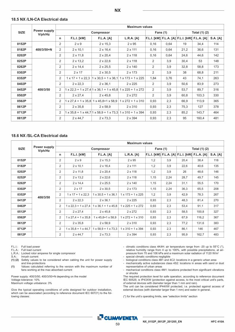
NX_0152P_0812P_201205_EN HFC 410A59
NX
F.L.I.: Full load powerF.L.A.: Full load currentL.R.A.: Locked rotor amperes for single compressorS.A.: Inrush current(1) (2) Safety values to be considered when cabling the unit for power supply
and line-protections(1) Values calculated referring to the version with the maximum number of
fans working at the max absorbed current
Power supply: 400/3/50, 400/3/50+N depending on the modelVoltage tolerance: 10%Maximum voltage unbalance: 3%
Give the typical operating conditions of units designed for outdoor installation,which can be associated (according to reference document IEC 60721) to the fol-lowing classes:
- climatic conditions class 4K4H: air temperature range from -20 up to 55°C (*),relative humidity range from 4 up to 100%, with possible precipitations, at air-pressure from 70 and 106 kPa and a maximum solar radiation of 1120 W/m2
- special climatic conditions negligible- biological conditions class 4B1 and 4C2: locations in a generic urban area- mechanically active substances class 4S2: locations in areas with sand or dustrepresentative of urban areas
- mechanical conditions class 4M1: locations protected from significant vibrationsor shocks
The required protection level for safe operation, according to reference documentIEC 60529, is IP43XW (protection against access, to the most critical unit's parts,of external devices with diameter larger than 1 mm and rain).The unit can be considered IP44XW protected, i.e. protected against access ofexternal devices (with diameter larger than 1 mm) and water in general.
(*) for the unit’s operating limits, see “selection limits” section
18.5 NX /LN-CA Electrical data
18.6 NX /SL-CA Electrical data
SIZE Power supplyV/ph/Hz
Maximum values
Compressor Fans (1) Total (1) (2)
n F.L.I. [kW] F.L.A. [A] L.R.A. [A] F.L.I. [kW] F.L.A. [A] F.L.I. [kW] F.L.A. [A] S.A. [A]
0152P
400/3/50+N
2 2 x 9 2 x 15,3 2 x 95 0,16 0,64 19 34,4 114
0182P 2 2 x 10,1 2 x 16,4 2 x 111 0,16 0,64 21,2 36,6 131
0202P 2 2 x 11,8 2 x 20,4 2 x 118 0,16 0,64 24,6 44,6 142
0252P
400/3/50
2 2 x 13,2 2 x 22,6 2 x 118 2 3,9 30,4 53 148
0262P 2 2 x 14,4 2 x 25,5 2 x 140 2 3,9 32,8 58,8 173
0302P 2 2 x 17 2 x 30,5 2 x 173 2 3,9 38 68,8 211
0352P 2 1 x 17 + 1 x 22,3 1 x 30,5 + 1 x 36,1 1 x 173 + 1 x 225 1,84 3,76 43 74,1 263
0402P 2 2 x 22,3 2 x 36,1 2 x 225 2 3,9 50,6 83,9 273
0452P 2 1 x 22,3 + 1 x 27,4 1 x 36,1 + 1 x 45,8 1 x 225 + 1 x 272 2 3,9 53,7 89,7 316
0502P 2 2 x 27,4 2 x 45,8 2 x 272 2 3,9 60,8 103,3 330
0562P 2 1 x 27,4 + 1 x 35,8 1 x 45,8+1 x 58,9 1 x 272 + 1 x 310 0,93 2,3 66,9 113,9 365
0612P 2 2 x 35,8 2 x 58,9 2 x 310 0,93 2,3 75,3 127 378
0712P 2 1 x 35,8 + 1 x 44,7 1 x 58,9 + 1 x 73,3 1 x 310 + 1 x 394 0,93 2,3 85,2 143,7 464
0812P 2 2 x 44,7 2 x 73,3 2 x 394 0,93 2,3 95 160,4 481
SIZE Power supplyV/ph/Hz
Maximum values
Compressor Fans (1) Total (1) (2)
n F.L.I. [kW] F.L.A. [A] L.R.A. [A] F.L.I. [kW] F.L.A. [A] F.L.I. [kW] F.L.A. [A] S.A. [A]
0152P
400/3/50
2 2 x 9 2 x 15,3 2 x 95 1,2 3,9 20,4 38,4 118
0182P 2 2 x 10,1 2 x 16,4 2 x 111 1,2 3,9 22,6 40,6 135
0202P 2 2 x 11,8 2 x 20,4 2 x 118 1,2 3,9 26 48,6 146
0252P 2 2 x 13,2 2 x 22,6 2 x 118 1,15 2,24 28,7 49,7 145
0262P 2 2 x 14,4 2 x 25,5 2 x 140 1,15 2,24 31,1 55,5 170
0302P 2 2 x 17 2 x 30,5 2 x 173 1,15 2,24 36,3 65,5 208
0352P 2 1 x 17 + 1 x 22,3 1 x 30,5 + 1 x 36,1 1 x 173 + 1 x 225 1,2 3,9 42,9 78,3 267
0412P 2 2 x 22,3 2 x 36,1 2 x 225 0,93 2,3 48,3 81,4 270
0462P 2 1 x 22,3 + 1 x 27,4 1 x 36,1 + 1 x 45,8 1 x 225 + 1 x 272 0,93 2,3 53,4 91,1 317
0512P 2 2 x 27,4 2 x 45,8 2 x 272 0,93 2,3 58,5 100,8 327
0562P 2 1 x 27,4 + 1 x 35,8 1 x 45,8+1 x 58,9 1 x 272 + 1 x 310 0,93 2,3 67,9 116,2 367
0612P 2 2 x 35,8 2 x 58,9 2 x 310 0,93 2,3 77,2 131,6 383
0712P 2 1 x 35,8 + 1 x 44,7 1 x 58,9 + 1 x 73,3 1 x 310 + 1 x 394 0,93 2,3 86,1 146 467
0812P 2 2 x 44,7 2 x 73,3 2 x 394 0,93 2,3 95,9 162,7 483

60NX_0152P_0812P_201205_EN HFC 410A
NX
SIZE Octave band [Hz]2000100050025012563 80004000
Total sound leveldB(A)Sound power level dB
SOUND POWER
84 84 80 79 79 76 68 56 830152P84 84 80 79 79 76 68 56 830182P85 85 81 80 80 77 69 57 840202P85 85 81 80 80 77 69 57 840252P85 85 81 80 80 77 69 57 840262P86 86 82 81 81 78 70 58 850302P87 87 83 82 82 79 71 59 860352P89 89 85 84 84 81 73 61 880402P89 89 85 84 84 81 73 61 880452P89 89 85 84 84 81 73 61 880502P90 90 86 85 85 82 74 62 890552P91 91 87 86 86 83 75 63 900602P91 91 87 86 86 83 75 63 900702P92 92 88 87 87 84 76 64 910802P
P
SIZE Octave band [Hz] at 10 m2000100050025012563 80004000
Total sound leveldB(A)Sound pressure level dB
SOUND PRESSURE LEVEL
52 52 48 47 47 44 36 24 510152P52 52 48 47 47 44 36 24 510182P53 53 49 48 48 45 37 25 520202P53 53 49 48 48 45 37 25 520252P53 53 49 48 48 45 37 25 520262P54 54 50 49 49 46 38 26 530302P55 55 51 50 50 47 39 27 540352P57 57 53 52 52 49 41 29 560402P57 57 53 52 52 49 41 29 560452P57 57 53 52 52 49 41 29 560502P58 58 54 53 53 50 42 30 570552P59 59 55 54 54 51 43 31 580602P59 59 55 54 54 51 43 31 580702P60 60 56 55 55 52 44 32 590802P
P
19.1 NX /K Full load sound level
Working conditionsPlant (side) cooling exchanger water (in/out) 12/7 °CSource (side) heat exchanger air (in) 35 °CSound power on the basis of measurements made in compliance with ISO 9614 and Eurovent 8/1 for Eurovent certified units; in com-pliance with ISO 3744 for non-certified unitsSuch certification refers specifically to the sound Power Level in dB(A). This is therefore the only acoustic data to be considered asbinding.
Working conditionsPlant (side) cooling exchanger water (in/out) 12/7 °CSource (side) heat exchanger air (in) 35 °CAverage sound pressure level, at 10 (m.) distance, unit in a free field on a reflective surface; non-binding value obtained from the soundpower level.
19. FULL LOAD SOUND LEVEL

NX_0152P_0812P_201205_EN HFC 410A61
NX
SIZE Octave band [Hz]2000100050025012563 80004000
Total sound leveldB(A)Sound power level dB
SOUND POWER
80 80 77 76 75 71 65 50 790152P80 80 77 76 75 71 65 50 790182P80 80 77 76 75 71 65 50 790202P81 81 78 77 76 72 66 51 800252P81 81 78 77 76 72 66 51 800262P81 81 78 77 76 72 66 51 800302P85 83 84 83 77 72 66 60 830352P85 83 84 83 77 72 66 60 830402P86 84 85 84 78 73 67 61 840452P86 84 85 84 78 73 67 61 840502P86 84 85 84 78 73 67 61 840552P87 85 86 85 79 74 68 62 850602P87 85 86 85 79 74 68 62 850702P87 85 86 85 79 74 68 62 850802P
P
SIZE Octave band [Hz] at 10 m2000100050025012563 80004000
Total sound leveldB(A)Sound pressure level dB
SOUND PRESSURE LEVEL
48 48 45 44 43 39 33 18 470152P48 48 45 44 43 39 33 18 470182P48 48 45 44 43 39 33 18 470202P49 49 46 45 44 40 34 19 480252P49 49 46 45 44 40 34 19 480262P49 49 46 45 44 40 34 19 480302P53 51 52 51 45 40 34 28 510352P53 51 52 51 45 40 34 28 510402P54 52 53 52 46 41 35 29 520452P54 52 53 52 46 41 35 29 520502P54 52 53 52 46 41 35 29 520552P55 53 54 53 47 42 36 30 530602P55 53 54 53 47 42 36 30 530702P55 53 54 53 47 42 36 30 530802P
P
19.2 NX /LN-K Full load sound level
Working conditionsPlant (side) cooling exchanger water (in/out) 12/7 °CSource (side) heat exchanger air (in) 35 °CSound power on the basis of measurements made in compliance with ISO 9614 and Eurovent 8/1 for Eurovent certified units; in com-pliance with ISO 3744 for non-certified unitsSuch certification refers specifically to the sound Power Level in dB(A). This is therefore the only acoustic data to be considered asbinding.
Working conditionsPlant (side) cooling exchanger water (in/out) 12/7 °CSource (side) heat exchanger air (in) 35 °CAverage sound pressure level, at 10 (m.) distance, unit in a free field on a reflective surface; non-binding value obtained from the soundpower level.

62NX_0152P_0812P_201205_EN HFC 410A
NX
SIZE Octave band [Hz]2000100050025012563 80004000
Total sound leveldB(A)Sound power level dB
SOUND POWER
81 79 77 74 71 66 60 56 760152P82 80 78 75 72 67 61 57 770182P82 80 78 75 72 67 61 57 770202P83 81 79 76 73 68 62 58 780252P83 81 79 76 73 68 62 58 780262P83 81 79 76 73 68 62 58 780302P84 82 80 77 74 69 63 59 790352P85 83 81 78 75 70 64 60 800402P85 84 82 79 76 71 65 61 810452P85 84 82 79 76 71 65 61 810502P87 85 83 81 76 72 66 62 820552P87 85 83 81 76 72 66 62 820602P88 86 84 82 76 73 67 63 830702P89 87 85 83 77 74 68 64 840802P
P
SIZE Octave band [Hz] at 10 m2000100050025012563 80004000
Total sound leveldB(A)Sound pressure level dB
SOUND PRESSURE LEVEL
49 47 45 42 39 34 28 24 440152P50 48 46 43 40 35 29 25 450182P50 48 46 43 40 35 29 25 450202P51 49 47 44 41 36 30 26 460252P51 49 47 44 41 36 30 26 460262P51 49 47 44 41 36 30 26 460302P52 50 48 45 42 37 31 27 470352P53 51 49 46 43 38 32 28 480402P53 52 50 47 44 39 33 29 490452P53 52 50 47 44 39 33 29 490502P55 53 51 49 44 40 34 30 500552P55 53 51 49 44 40 34 30 500602P56 54 52 50 44 41 35 31 510702P57 55 53 51 45 42 36 32 520802P
P
19.3 NX /SL-K Full load sound level
Working conditionsPlant (side) cooling exchanger water (in/out) 12/7 °CSource (side) heat exchanger air (in) 35 °CSound power on the basis of measurements made in compliance with ISO 9614 and Eurovent 8/1 for Eurovent certified units; in com-pliance with ISO 3744 for non-certified unitsSuch certification refers specifically to the sound Power Level in dB(A). This is therefore the only acoustic data to be considered asbinding.
Working conditionsPlant (side) cooling exchanger water (in/out) 12/7 °CSource (side) heat exchanger air (in) 35 °CAverage sound pressure level, at 10 (m.) distance, unit in a free field on a reflective surface; non-binding value obtained from the soundpower level.

NX_0152P_0812P_201205_EN HFC 410A63
NX
SIZE Octave band [Hz]2000100050025012563 80004000
Total sound leveldB(A)Sound power level dB
SOUND POWER
85 85 81 80 80 77 69 57 840152P85 85 81 80 80 77 69 57 840182P86 86 82 81 81 78 70 58 850202P86 86 82 81 81 78 70 58 850252P87 87 83 82 82 79 71 59 860262P89 89 85 84 84 81 73 61 880302P89 89 85 84 84 81 73 61 880352P91 91 87 86 86 83 75 63 900402P91 91 87 86 86 83 75 63 900452P91 91 87 86 86 83 75 63 900502P92 92 88 87 87 84 76 64 910562P92 92 88 87 87 84 76 64 910612P93 93 89 88 88 85 77 65 920712P94 94 90 89 89 86 78 66 930812P
P
SIZE Octave band [Hz] at 10 m2000100050025012563 80004000
Total sound leveldB(A)Sound pressure level dB
SOUND PRESSURE LEVEL
53 53 49 48 48 45 37 25 520152P53 53 49 48 48 45 37 25 520182P54 54 50 49 49 46 38 26 530202P54 54 50 49 49 46 38 26 530252P55 55 51 50 50 47 39 27 540262P57 57 53 52 52 49 41 29 560302P57 57 53 52 52 49 41 29 560352P59 59 55 54 54 51 43 31 580402P59 59 55 54 54 51 43 31 580452P59 59 55 54 54 51 43 31 580502P60 60 56 55 55 52 44 32 590562P60 60 56 55 55 52 44 32 590612P61 61 57 56 56 53 45 33 600712P62 62 58 57 57 54 46 34 610812P
P
19.4 NX /CA Full load sound level
Working conditionsPlant (side) cooling exchanger water (in/out) 12/7 °CSource (side) heat exchanger air (in) 35 °CSound power on the basis of measurements made in compliance with ISO 9614 and Eurovent 8/1 for Eurovent certified units; in com-pliance with ISO 3744 for non-certified unitsSuch certification refers specifically to the sound Power Level in dB(A). This is therefore the only acoustic data to be considered asbinding.
Working conditionsPlant (side) cooling exchanger water (in/out) 12/7 °CSource (side) heat exchanger air (in) 35 °CAverage sound pressure level, at 10 (m.) distance, unit in a free field on a reflective surface; non-binding value obtained from the soundpower level.

64NX_0152P_0812P_201205_EN HFC 410A
NX
SIZE Octave band [Hz]2000100050025012563 80004000
Total sound leveldB(A)Sound power level dB
SOUND POWER
81 81 78 77 76 72 66 51 800152P81 81 78 77 76 72 66 51 800182P81 81 78 77 76 72 66 51 800202P83 81 82 81 75 70 64 58 810252P83 81 82 81 75 70 64 58 810262P84 82 83 82 76 71 65 59 820302P86 84 85 84 78 73 67 61 840352P86 84 85 84 78 73 67 61 840402P86 84 85 84 78 73 67 61 840452P87 85 86 85 79 74 68 62 850502P88 86 87 86 80 75 69 63 860562P88 86 87 86 80 75 69 63 860612P89 87 88 87 81 76 70 64 870712P90 88 89 88 82 77 71 65 880812P
P
SIZE Octave band [Hz] at 10 m2000100050025012563 80004000
Total sound leveldB(A)Sound pressure level dB
SOUND PRESSURE LEVEL
49 49 46 45 44 40 34 19 480152P49 49 46 45 44 40 34 19 480182P49 49 46 45 44 40 34 19 480202P51 49 50 49 43 38 32 26 490252P51 49 50 49 43 38 32 26 490262P52 50 51 50 44 39 33 27 500302P54 52 53 52 46 41 35 29 520352P54 52 53 52 46 41 35 29 520402P54 52 53 52 46 41 35 29 520452P55 53 54 53 47 42 36 30 530502P56 54 55 54 48 43 37 31 540562P56 54 55 54 48 43 37 31 540612P57 55 56 55 49 44 38 32 550712P58 56 57 56 50 45 39 33 560812P
P
19.5 NX /LN-CA Full load sound level
Working conditionsPlant (side) cooling exchanger water (in/out) 12/7 °CSource (side) heat exchanger air (in) 35 °CSound power on the basis of measurements made in compliance with ISO 9614 and Eurovent 8/1 for Eurovent certified units; in com-pliance with ISO 3744 for non-certified unitsSuch certification refers specifically to the sound Power Level in dB(A). This is therefore the only acoustic data to be considered asbinding.
Working conditionsPlant (side) cooling exchanger water (in/out) 12/7 °CSource (side) heat exchanger air (in) 35 °CAverage sound pressure level, at 10 (m.) distance, unit in a free field on a reflective surface; non-binding value obtained from the soundpower level.

NX_0152P_0812P_201205_EN HFC 410A65
NX
SIZE Octave band [Hz]2000100050025012563 80004000
Total sound leveldB(A)Sound power level dB
SOUND POWER
82 80 78 75 72 67 61 57 770152P83 81 79 76 73 68 62 58 780182P83 81 79 76 73 68 62 58 780202P84 82 80 77 74 69 63 59 790252P84 82 80 77 74 69 63 59 790262P84 82 80 77 74 69 63 59 790302P85 83 81 78 75 70 64 60 800352P85 84 82 79 76 71 65 61 810412P87 85 83 81 76 72 66 62 820462P87 85 83 81 76 72 66 62 820512P88 86 84 82 76 73 67 63 830562P89 87 85 83 77 74 68 64 840612P89 88 86 84 79 74 68 64 850712P89 89 87 85 80 75 69 64 860812P
P
SIZE Octave band [Hz] at 10 m2000100050025012563 80004000
Total sound leveldB(A)Sound pressure level dB
SOUND PRESSURE LEVEL
50 48 46 43 40 35 29 25 450152P51 49 47 44 41 36 30 26 460182P51 49 47 44 41 36 30 26 460202P52 50 48 45 42 37 31 27 470252P52 50 48 45 42 37 31 27 470262P52 50 48 45 42 37 31 27 470302P53 51 49 46 43 38 32 28 480352P53 52 50 47 44 39 33 29 490412P55 53 51 49 44 40 34 30 500462P55 53 51 49 44 40 34 30 500512P56 54 52 50 44 41 35 31 510562P57 55 53 51 45 42 36 32 520612P57 56 54 52 47 42 36 32 530712P57 57 55 53 48 43 37 32 540812P
P
19.6 NX /SL-CA Full load sound level
Working conditionsPlant (side) cooling exchanger water (in/out) 12/7 °CSource (side) heat exchanger air (in) 35 °CSound power on the basis of measurements made in compliance with ISO 9614 and Eurovent 8/1 for Eurovent certified units; in com-pliance with ISO 3744 for non-certified unitsSuch certification refers specifically to the sound Power Level in dB(A). This is therefore the only acoustic data to be considered asbinding.
Working conditionsPlant (side) cooling exchanger water (in/out) 12/7 °CSource (side) heat exchanger air (in) 35 °CAverage sound pressure level, at 10 (m.) distance, unit in a free field on a reflective surface; non-binding value obtained from the soundpower level.

66NX_0152P_0812P_201205_EN HFC 410A
NX
20. DIMENSIONAL DRAWINGS
Solo
perv
ersio
neNX
/D
SU
PP
OR
TIN
GB
AS
EM
EN
T
W1
W2
W5
W6
N°
6H
OLE
SØ
16N
°6
FOR
IØ16
SPAZ
IODI
RISP
ETTO
MINI
MUM
CLEA
RANC
E
SPAZ
IODI
RISP
ETTO
MINI
MUM
CLEA
RANC
E
W3
W4-E
NTRA
TAAR
IA
-AIR
OUTL
ET-U
SCITA
ARIA
-AIR
INLE
T
-CEN
TER
OFGR
AVIT
Y-B
ARIC
ENTR
O
-EVA
PORA
TOR
WAT
ERIN
LET
-ENT
RATA
ACQU
AEV
APOR
ATOR
E1
-EVA
PORA
TOR
WAT
EROU
TLET
-USC
ITAAC
QUA
EVAP
ORAT
ORE
2
-POW
ERIN
LET
-ING
RESS
OLIN
EAEL
ETTR
ICA
3
-DES
UPER
HEAT
ERS
WAT
ERIN
LET
-ENT
RATA
ACQU
ADE
SURR
ISCA
LDAT
ORI
4
-DES
UPER
HEAT
ERS
WAT
EROU
TLET
-USC
ITAAC
QUA
DESU
RRIS
CALD
ATOR
I5
12
12
1
WIT
H1-
2PUM
PSCO
N1-
2POM
PE
WIT
HPU
MPS
andS
TORA
GETA
NKCO
NPO
MPE
eACC
UMUL
O
15
4
45
54
SOLL
EVAM
ENTO
LIFTI
NG
ATTE
NZI
ON
E-A
TTE
NTI
ON
:U
TILI
ZZA
RE
n°4
FUN
IDIS
OLL
EVA
ME
NTO
DIP
AR
ILU
NG
HE
ZZA
US
En°
4LI
FTIN
GR
OP
ES
WIT
HE
QU
AL
LEN
GH
TO
NLY
22
WIT
HOUT
HYDR
ONIC
KIT
SENZ
AKI
TID
RONI
CO
15
41
C2C1
3
BA
H
45
45
"Longitudinal V shaped coil" structure

NX_0152P_0812P_201205_EN HFC 410A67
NX
Solo
perv
ersio
neNX
/DB
H
B
SPAZ
IODI
RISP
ETTO
MIN
IMUM
CLEA
RANC
E
SPAZ
IODI
RISP
ETTO
MIN
IMUM
CLEA
RANC
E
BASE
D'AP
POG
GIO
-SU
PPO
RTIN
GBA
SEM
ENT
A
LIFTI
NGSO
LLEV
AMEN
TO
52
3
C2C1
21
21
WIT
HOUT
HYDR
ONIC
KIT
SENZ
AKI
TID
RONI
CO
WIT
H1-
2PUM
PSCO
N1-
2POM
PE
WIT
HPU
MPS
andS
TORA
GETA
NKCO
NPO
MPE
eACC
UMUL
O
45
45
R R
R3
R4
14
-ENT
RATA
ARIA
-AIR
OUTL
ET-U
SCITA
ARIA
-AIR
INLE
T
-CEN
TER
OFGR
AVIT
Y-B
ARIC
ENTR
O
-EVA
PORA
TOR
WAT
ERIN
LET
-ENT
RATA
ACQU
AEV
APOR
ATOR
E1
-EVA
PORA
TOR
WAT
EROU
TLET
-USC
ITAAC
QUA
EVAP
ORAT
ORE
2
-POW
ERIN
LET
-ING
RESS
OLIN
EAEL
ETTR
ICA
3
-DES
UPER
HEAT
ERS
WAT
ERIN
LET
-ENT
RATA
ACQU
ADE
SURR
ISCA
LDAT
ORI
4
-DES
UPER
HEAT
ERS
WAT
EROU
TLET
-USC
ITAAC
QUA
DESU
RRIS
CALD
ATOR
I5
W1
W3
W5
W7
W2
W4
W6
W8
21
21
21
45
"Horizontal V shaped coil" structure
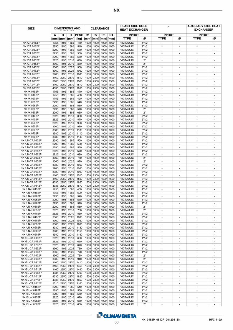
68NX_0152P_0812P_201205_EN HFC 410A
NX
ØIN/OUT
ØIN/OUTIN/OUTR4
[mm]R3
[mm]R2
[mm]R1
[mm]PESO[kg]
H[mm]
B[mm]
A[mm]
SIZE DIMENSIONS AND WEIGHTS
CLEARANCEPLANT SIDE COLD HEAT EXCHANGER
ØTYPE TYPE TYPE
- AUXILIARY SIDE HEAT EXCHANGER
1755 1195 1885 480 1000 1000 1000 1000 VICTAULIC 1"1/2 - - - -NX /CA 0152P2290 1195 1885 540 1000 1000 1000 1000 VICTAULIC 1"1/2 - - - -NX /CA 0182P2290 1195 1885 550 1000 1000 1000 1000 VICTAULIC 1"1/2 - - - -NX /CA 0202P2290 1195 1885 560 1000 1000 1000 1000 VICTAULIC 1"1/2 - - - -NX /CA 0252P2290 1195 1885 570 1000 1000 1000 1000 VICTAULIC 1"1/2 - - - -NX /CA 0262P2825 1195 2010 680 1000 1000 1000 1000 VICTAULIC 2" - - - -NX /CA 0302P3360 1195 2010 830 1000 1000 1000 1000 VICTAULIC 2" - - - -NX /CA 0352P3360 1195 2025 960 1000 1000 1000 1000 VICTAULIC 2"1/2 - - - -NX /CA 0402P3360 1195 2025 1000 1000 1000 1000 1000 VICTAULIC 2"1/2 - - - -NX /CA 0452P3980 1195 2010 1080 1000 1000 1000 1000 VICTAULIC 2"1/2 - - - -NX /CA 0502P3160 2250 2170 1510 1500 2300 1500 1500 VICTAULIC 2"1/2 - - - -NX /CA 0562P3160 2250 2170 1560 1500 2300 1500 1500 VICTAULIC 2"1/2 - - - -NX /CA 0612P3160 2250 2170 1570 1500 2300 1500 1500 VICTAULIC 2"1/2 - - - -NX /CA 0712P4335 2250 2170 1850 1500 2300 1500 1500 VICTAULIC 2"1/2 - - - -NX /CA 0812P1755 1195 1885 470 1000 1000 1000 1000 VICTAULIC 1"1/2 - - - -NX /K 0152P1755 1195 1885 480 1000 1000 1000 1000 VICTAULIC 1"1/2 - - - -NX /K 0182P1755 1195 1885 490 1000 1000 1000 1000 VICTAULIC 1"1/2 - - - -NX /K 0202P2290 1195 1885 540 1000 1000 1000 1000 VICTAULIC 1"1/2 - - - -NX /K 0252P2290 1195 1885 550 1000 1000 1000 1000 VICTAULIC 1"1/2 - - - -NX /K 0262P2290 1195 1885 570 1000 1000 1000 1000 VICTAULIC 2" - - - -NX /K 0302P2290 1195 1885 660 1000 1000 1000 1000 VICTAULIC 2" - - - -NX /K 0352P2825 1195 2010 830 1000 1000 1000 1000 VICTAULIC 2"1/2 - - - -NX /K 0402P2825 1195 2010 870 1000 1000 1000 1000 VICTAULIC 2"1/2 - - - -NX /K 0452P2825 1195 2010 900 1000 1000 1000 1000 VICTAULIC 2"1/2 - - - -NX /K 0502P3360 1195 2010 980 1000 1000 1000 1000 VICTAULIC 2"1/2 - - - -NX /K 0552P3980 1195 2010 1130 1000 1000 1000 1000 VICTAULIC 2"1/2 - - - -NX /K 0602P3980 1195 2010 1110 1000 1000 1000 1000 VICTAULIC 2"1/2 - - - -NX /K 0702P3980 1195 2010 1140 1000 1000 1000 1000 VICTAULIC 2"1/2 - - - -NX /K 0802P2290 1195 1885 550 1000 1000 1000 1000 VICTAULIC 1"1/2 - - - -NX /LN-CA 0152P2290 1195 1885 560 1000 1000 1000 1000 VICTAULIC 1"1/2 - - - -NX /LN-CA 0182P2290 1195 1885 560 1000 1000 1000 1000 VICTAULIC 1"1/2 - - - -NX /LN-CA 0202P2825 1195 2010 670 1000 1000 1000 1000 VICTAULIC 1"1/2 - - - -NX /LN-CA 0252P2825 1195 2010 680 1000 1000 1000 1000 VICTAULIC 1"1/2 - - - -NX /LN-CA 0262P3360 1195 2010 750 1000 1000 1000 1000 VICTAULIC 2" - - - -NX /LN-CA 0302P3360 1195 2025 870 1000 1000 1000 1000 VICTAULIC 2" - - - -NX /LN-CA 0352P3980 1195 2010 1050 1000 1000 1000 1000 VICTAULIC 2"1/2 - - - -NX /LN-CA 0402P3980 1195 2010 1080 1000 1000 1000 1000 VICTAULIC 2"1/2 - - - -NX /LN-CA 0452P3980 1195 2010 1090 1000 1000 1000 1000 VICTAULIC 2"1/2 - - - -NX /LN-CA 0502P3160 2250 2170 1510 1500 2300 1500 1500 VICTAULIC 2"1/2 - - - -NX /LN-CA 0562P3160 2250 2170 1550 1500 2300 1500 1500 VICTAULIC 2"1/2 - - - -NX /LN-CA 0612P4335 2250 2170 1850 1500 2300 1500 1500 VICTAULIC 2"1/2 - - - -NX /LN-CA 0712P4335 2250 2170 1870 1500 2300 1500 1500 VICTAULIC 2"1/2 - - - -NX /LN-CA 0812P1755 1195 1885 480 1000 1000 1000 1000 VICTAULIC 1"1/2 - - - -NX /LN-K 0152P1755 1195 1885 500 1000 1000 1000 1000 VICTAULIC 1"1/2 - - - -NX /LN-K 0182P2290 1195 1885 540 1000 1000 1000 1000 VICTAULIC 1"1/2 - - - -NX /LN-K 0202P2290 1195 1885 570 1000 1000 1000 1000 VICTAULIC 1"1/2 - - - -NX /LN-K 0252P2290 1195 1885 570 1000 1000 1000 1000 VICTAULIC 1"1/2 - - - -NX /LN-K 0262P2290 1195 1885 580 1000 1000 1000 1000 VICTAULIC 2" - - - -NX /LN-K 0302P2825 1195 2010 780 1000 1000 1000 1000 VICTAULIC 2" - - - -NX /LN-K 0352P2825 1195 2010 880 1000 1000 1000 1000 VICTAULIC 2"1/2 - - - -NX /LN-K 0402P3360 1195 2025 1000 1000 1000 1000 1000 VICTAULIC 2"1/2 - - - -NX /LN-K 0452P3360 1195 2025 1030 1000 1000 1000 1000 VICTAULIC 2"1/2 - - - -NX /LN-K 0502P3360 1195 2025 1060 1000 1000 1000 1000 VICTAULIC 2"1/2 - - - -NX /LN-K 0552P3980 1195 2010 1180 1000 1000 1000 1000 VICTAULIC 2"1/2 - - - -NX /LN-K 0602P3980 1195 2010 1150 1000 1000 1000 1000 VICTAULIC 2"1/2 - - - -NX /LN-K 0702P3980 1195 2010 1180 1000 1000 1000 1000 VICTAULIC 2"1/2 - - - -NX /LN-K 0802P2825 1195 2010 650 1000 1000 1000 1000 VICTAULIC 1"1/2 - - - -NX /SL-CA 0152P2825 1195 2010 660 1000 1000 1000 1000 VICTAULIC 1"1/2 - - - -NX /SL-CA 0182P2825 1195 2010 670 1000 1000 1000 1000 VICTAULIC 1"1/2 - - - -NX /SL-CA 0202P3360 1195 2025 760 1000 1000 1000 1000 VICTAULIC 1"1/2 - - - -NX /SL-CA 0252P3360 1195 2025 770 1000 1000 1000 1000 VICTAULIC 1"1/2 - - - -NX /SL-CA 0262P3360 1195 2025 780 1000 1000 1000 1000 VICTAULIC 2" - - - -NX /SL-CA 0302P3980 1195 2010 940 1000 1000 1000 1000 VICTAULIC 2" - - - -NX /SL-CA 0352P3160 2250 2170 1410 1500 2300 1500 1500 VICTAULIC 2"1/2 - - - -NX /SL-CA 0412P3160 2250 2170 1450 1500 2300 1500 1500 VICTAULIC 2"1/2 - - - -NX /SL-CA 0462P3160 2250 2170 1480 1500 2300 1500 1500 VICTAULIC 2"1/2 - - - -NX /SL-CA 0512P4335 2250 2170 1760 1500 2300 1500 1500 VICTAULIC 2"1/2 - - - -NX /SL-CA 0562P4335 2250 2170 1820 1500 2300 1500 1500 VICTAULIC 2"1/2 - - - -NX /SL-CA 0612P4335 2250 2170 1850 1500 2300 1500 1500 VICTAULIC 2"1/2 - - - -NX /SL-CA 0712P5510 2250 2170 2160 1500 2300 1500 1500 VICTAULIC 2"1/2 - - - -NX /SL-CA 0812P2290 1195 1885 540 1000 1000 1000 1000 VICTAULIC 1"1/2 - - - -NX /SL-K 0152P2290 1195 1885 550 1000 1000 1000 1000 VICTAULIC 1"1/2 - - - -NX /SL-K 0182P2290 1195 1885 560 1000 1000 1000 1000 VICTAULIC 1"1/2 - - - -NX /SL-K 0202P2825 1195 2010 670 1000 1000 1000 1000 VICTAULIC 1"1/2 - - - -NX /SL-K 0252P2825 1195 2010 680 1000 1000 1000 1000 VICTAULIC 1"1/2 - - - -NX /SL-K 0262P2825 1195 2010 680 1000 1000 1000 1000 VICTAULIC 2" - - - -NX /SL-K 0302P
8

NX_0152P_0812P_201205_EN HFC 410A69
NX
3360 1195 2025 860 1000 1000 1000 1000 VICTAULIC 2" - - - -NX /SL-K 0352P3360 1195 2025 960 1000 1000 1000 1000 VICTAULIC 2"1/2 - - - -NX /SL-K 0402P3980 1195 2010 1070 1000 1000 1000 1000 VICTAULIC 2"1/2 - - - -NX /SL-K 0452P3980 1195 2010 1080 1000 1000 1000 1000 VICTAULIC 2"1/2 - - - -NX /SL-K 0502P3980 1195 2010 1110 1000 1000 1000 1000 VICTAULIC 2"1/2 - - - -NX /SL-K 0552P3980 1195 2010 1180 1000 1000 1000 1000 VICTAULIC 2"1/2 - - - -NX /SL-K 0602P3980 1195 2010 1150 1000 1000 1000 1000 VICTAULIC 2"1/2 - - - -NX /SL-K 0702P3980 1195 2010 1180 1000 1000 1000 1000 VICTAULIC 2"1/2 - - - -NX /SL-K 0802P1755 1195 1885 480 1000 1000 1000 1000 VICTAULIC 1"1/2 - - GAS 1" 1/4NX /D /CA 0152P2290 1195 1885 540 1000 1000 1000 1000 VICTAULIC 1"1/2 - - GAS 1" 1/4NX /D /CA 0182P2290 1195 1885 550 1000 1000 1000 1000 VICTAULIC 1"1/2 - - GAS 1" 1/4NX /D /CA 0202P2290 1195 1885 560 1000 1000 1000 1000 VICTAULIC 1"1/2 - - GAS 1" 1/4NX /D /CA 0252P2290 1195 1885 570 1000 1000 1000 1000 VICTAULIC 1"1/2 - - GAS 1" 1/4NX /D /CA 0262P2825 1195 2010 680 1000 1000 1000 1000 VICTAULIC 2" - - GAS 1" 1/4NX /D /CA 0302P3360 1195 2010 830 1000 1000 1000 1000 VICTAULIC 2" - - GAS 1" 1/4NX /D /CA 0352P3360 1195 2025 960 1000 1000 1000 1000 VICTAULIC 2"1/2 - - GAS 1" 1/4NX /D /CA 0402P3360 1195 2025 1000 1000 1000 1000 1000 VICTAULIC 2"1/2 - - GAS 1" 1/4NX /D /CA 0452P3980 1195 2010 1080 1000 1000 1000 1000 VICTAULIC 2"1/2 - - GAS 1" 1/4NX /D /CA 0502P3160 2250 2170 1510 1500 2300 1500 1500 VICTAULIC 2"1/2 - - GAS 1" 1/4NX /D /CA 0562P3160 2250 2170 1560 1500 2300 1500 1500 VICTAULIC 2"1/2 - - GAS 1" 1/4NX /D /CA 0612P3160 2250 2170 1570 1500 2300 1500 1500 VICTAULIC 2"1/2 - - GAS 1" 1/4NX /D /CA 0712P4335 2250 2170 1850 1500 2300 1500 1500 VICTAULIC 2"1/2 - - GAS 1" 1/4NX /D /CA 0812P1755 1195 1885 470 1000 1000 1000 1000 VICTAULIC 1"1/2 - - GAS 1" 1/4NX /D /K 0152P1755 1195 1885 480 1000 1000 1000 1000 VICTAULIC 1"1/2 - - GAS 1" 1/4NX /D /K 0182P1755 1195 1885 490 1000 1000 1000 1000 VICTAULIC 1"1/2 - - GAS 1" 1/4NX /D /K 0202P2290 1195 1885 540 1000 1000 1000 1000 VICTAULIC 1"1/2 - - GAS 1" 1/4NX /D /K 0252P2290 1195 1885 550 1000 1000 1000 1000 VICTAULIC 1"1/2 - - GAS 1" 1/4NX /D /K 0262P2290 1195 1885 570 1000 1000 1000 1000 VICTAULIC 2" - - GAS 1" 1/4NX /D /K 0302P2290 1195 1885 660 1000 1000 1000 1000 VICTAULIC 2" - - GAS 1" 1/4NX /D /K 0352P2825 1195 2010 830 1000 1000 1000 1000 VICTAULIC 2"1/2 - - GAS 1" 1/4NX /D /K 0402P2825 1195 2010 870 1000 1000 1000 1000 VICTAULIC 2"1/2 - - GAS 1" 1/4NX /D /K 0452P2825 1195 2010 900 1000 1000 1000 1000 VICTAULIC 2"1/2 - - GAS 1" 1/4NX /D /K 0502P3360 1195 2010 980 1000 1000 1000 1000 VICTAULIC 2"1/2 - - GAS 1" 1/4NX /D /K 0552P3980 1195 2010 1130 1000 1000 1000 1000 VICTAULIC 2"1/2 - - GAS 1" 1/4NX /D /K 0602P3980 1195 2010 1110 1000 1000 1000 1000 VICTAULIC 2"1/2 - - GAS 1" 1/4NX /D /K 0702P3980 1195 2010 1140 1000 1000 1000 1000 VICTAULIC 2"1/2 - - GAS 1" 1/4NX /D /K 0802P2290 1195 1885 550 1000 1000 1000 1000 VICTAULIC 1"1/2 - - GAS 1" 1/4NX /D /LN-CA 0152P2290 1195 1885 560 1000 1000 1000 1000 VICTAULIC 1"1/2 - - GAS 1" 1/4NX /D /LN-CA 0182P2290 1195 1885 560 1000 1000 1000 1000 VICTAULIC 1"1/2 - - GAS 1" 1/4NX /D /LN-CA 0202P2825 1195 2010 670 1000 1000 1000 1000 VICTAULIC 1"1/2 - - GAS 1" 1/4NX /D /LN-CA 0252P2825 1195 2010 680 1000 1000 1000 1000 VICTAULIC 1"1/2 - - GAS 1" 1/4NX /D /LN-CA 0262P3360 1195 2010 750 1000 1000 1000 1000 VICTAULIC 2" - - GAS 1" 1/4NX /D /LN-CA 0302P3360 1195 2025 870 1000 1000 1000 1000 VICTAULIC 2" - - GAS 1" 1/4NX /D /LN-CA 0352P3980 1195 2010 1050 1000 1000 1000 1000 VICTAULIC 2"1/2 - - GAS 1" 1/4NX /D /LN-CA 0402P3980 1195 2010 1080 1000 1000 1000 1000 VICTAULIC 2"1/2 - - GAS 1" 1/4NX /D /LN-CA 0452P3980 1195 2010 1090 1000 1000 1000 1000 VICTAULIC 2"1/2 - - GAS 1" 1/4NX /D /LN-CA 0502P3160 2250 2170 1510 1500 2300 1500 1500 VICTAULIC 2"1/2 - - GAS 1" 1/4NX /D /LN-CA 0562P3160 2250 2170 1550 1500 2300 1500 1500 VICTAULIC 2"1/2 - - GAS 1" 1/4NX /D /LN-CA 0612P4335 2250 2170 1850 1500 2300 1500 1500 VICTAULIC 2"1/2 - - GAS 1" 1/4NX /D /LN-CA 0712P4335 2250 2170 1870 1500 2300 1500 1500 VICTAULIC 2"1/2 - - GAS 1" 1/4NX /D /LN-CA 0812P1755 1195 1885 480 1000 1000 1000 1000 VICTAULIC 1"1/2 - - GAS 1" 1/4NX /D /LN-K 0152P1755 1195 1885 500 1000 1000 1000 1000 VICTAULIC 1"1/2 - - GAS 1" 1/4NX /D /LN-K 0182P2290 1195 1885 540 1000 1000 1000 1000 VICTAULIC 1"1/2 - - GAS 1" 1/4NX /D /LN-K 0202P2290 1195 1885 570 1000 1000 1000 1000 VICTAULIC 1"1/2 - - GAS 1" 1/4NX /D /LN-K 0252P2290 1195 1885 570 1000 1000 1000 1000 VICTAULIC 1"1/2 - - GAS 1" 1/4NX /D /LN-K 0262P2290 1195 1885 580 1000 1000 1000 1000 VICTAULIC 2" - - GAS 1" 1/4NX /D /LN-K 0302P2825 1195 2010 780 1000 1000 1000 1000 VICTAULIC 2" - - GAS 1" 1/4NX /D /LN-K 0352P2825 1195 2010 880 1000 1000 1000 1000 VICTAULIC 2"1/2 - - GAS 1" 1/4NX /D /LN-K 0402P3360 1195 2025 1000 1000 1000 1000 1000 VICTAULIC 2"1/2 - - GAS 1" 1/4NX /D /LN-K 0452P3360 1195 2025 1030 1000 1000 1000 1000 VICTAULIC 2"1/2 - - GAS 1" 1/4NX /D /LN-K 0502P3360 1195 2025 1060 1000 1000 1000 1000 VICTAULIC 2"1/2 - - GAS 1" 1/4NX /D /LN-K 0552P3980 1195 2010 1180 1000 1000 1000 1000 VICTAULIC 2"1/2 - - GAS 1" 1/4NX /D /LN-K 0602P3980 1195 2010 1150 1000 1000 1000 1000 VICTAULIC 2"1/2 - - GAS 1" 1/4NX /D /LN-K 0702P3980 1195 2010 1180 1000 1000 1000 1000 VICTAULIC 2"1/2 - - GAS 1" 1/4NX /D /LN-K 0802P2825 1195 2010 650 1000 1000 1000 1000 VICTAULIC 1"1/2 - - GAS 1" 1/4NX /D /SL-CA 0152P2825 1195 2010 660 1000 1000 1000 1000 VICTAULIC 1"1/2 - - GAS 1" 1/4NX /D /SL-CA 0182P2825 1195 2010 670 1000 1000 1000 1000 VICTAULIC 1"1/2 - - GAS 1" 1/4NX /D /SL-CA 0202P3360 1195 2025 760 1000 1000 1000 1000 VICTAULIC 1"1/2 - - GAS 1" 1/4NX /D /SL-CA 0252P3360 1195 2025 770 1000 1000 1000 1000 VICTAULIC 1"1/2 - - GAS 1" 1/4NX /D /SL-CA 0262P3360 1195 2025 780 1000 1000 1000 1000 VICTAULIC 2" - - GAS 1" 1/4NX /D /SL-CA 0302P3980 1195 2010 940 1000 1000 1000 1000 VICTAULIC 2" - - GAS 1" 1/4NX /D /SL-CA 0352P3160 2250 2170 1410 1500 2300 1500 1500 VICTAULIC 2"1/2 - - GAS 1" 1/4NX /D /SL-CA 0412P3160 2250 2170 1450 1500 2300 1500 1500 VICTAULIC 2"1/2 - - GAS 1" 1/4NX /D /SL-CA 0462P3160 2250 2170 1480 1500 2300 1500 1500 VICTAULIC 2"1/2 - - GAS 1" 1/4NX /D /SL-CA 0512P4335 2250 2170 1760 1500 2300 1500 1500 VICTAULIC 2"1/2 - - GAS 1" 1/4NX /D /SL-CA 0562P4335 2250 2170 1820 1500 2300 1500 1500 VICTAULIC 2"1/2 - - GAS 1" 1/4NX /D /SL-CA 0612P4335 2250 2170 1850 1500 2300 1500 1500 VICTAULIC 2"1/2 - - GAS 1" 1/4NX /D /SL-CA 0712P5510 2250 2170 2160 1500 2300 1500 1500 VICTAULIC 2"1/2 - - GAS 1" 1/4NX /D /SL-CA 0812P2290 1195 1885 540 1000 1000 1000 1000 VICTAULIC 1"1/2 - - GAS 1" 1/4NX /D /SL-K 0152P2290 1195 1885 550 1000 1000 1000 1000 VICTAULIC 1"1/2 - - GAS 1" 1/4NX /D /SL-K 0182P2290 1195 1885 560 1000 1000 1000 1000 VICTAULIC 1"1/2 - - GAS 1" 1/4NX /D /SL-K 0202P
8

70NX_0152P_0812P_201205_EN HFC 410A
NX
2825 1195 2010 670 1000 1000 1000 1000 VICTAULIC 1"1/2 - - GAS 1" 1/4NX /D /SL-K 0252P2825 1195 2010 680 1000 1000 1000 1000 VICTAULIC 1"1/2 - - GAS 1" 1/4NX /D /SL-K 0262P2825 1195 2010 680 1000 1000 1000 1000 VICTAULIC 2" - - GAS 1" 1/4NX /D /SL-K 0302P3360 1195 2025 860 1000 1000 1000 1000 VICTAULIC 2" - - GAS 1" 1/4NX /D /SL-K 0352P3360 1195 2025 960 1000 1000 1000 1000 VICTAULIC 2"1/2 - - GAS 1" 1/4NX /D /SL-K 0402P3980 1195 2010 1070 1000 1000 1000 1000 VICTAULIC 2"1/2 - - GAS 1" 1/4NX /D /SL-K 0452P3980 1195 2010 1080 1000 1000 1000 1000 VICTAULIC 2"1/2 - - GAS 1" 1/4NX /D /SL-K 0502P3980 1195 2010 1110 1000 1000 1000 1000 VICTAULIC 2"1/2 - - GAS 1" 1/4NX /D /SL-K 0552P3980 1195 2010 1180 1000 1000 1000 1000 VICTAULIC 2"1/2 - - GAS 1" 1/4NX /D /SL-K 0602P3980 1195 2010 1150 1000 1000 1000 1000 VICTAULIC 2"1/2 - - GAS 1" 1/4NX /D /SL-K 0702P3980 1195 2010 1180 1000 1000 1000 1000 VICTAULIC 2"1/2 - - GAS 1" 1/4NX /D /SL-K 0802P
8

NX_0152P_0812P_201205_EN HFC 410A71
NX
LEGEND OF PIPE CONNECTIONS
UNI ISO 228/1Pipe threads where pressure-tight joints are not made on the threads - Designation, dimensions and tolerancesUsed terminology:G: Pipe threads where pressure-tight joints are not made on the threadsA: Close tolerance class for external pipe threads where pressure-tight joints are not made on the threadsB: Wider tolerance class for external pipe threads where pressure-tight joints are not made on the threads Internal threads: G letter followed by thread mark (only tolerance class)External threads: G letter followed by thread mark and by A letter for A class external threads or by B letter for B class external threads.
UNI ISO 7/1Pipe threads where pressure-tight joints are made on the threads - Designation, dimensions and tolerancesUsed terminology:Rp: Internal cylindrical threads where pressure-tight joints are made on the threadsRc: Internal conical threads where pressure-tight joints are made on the threadsR: External conical threads where pressure-tight joints are made on the threadsInternal cylindrical threads: R letter followed by p letterInternal conical threads: R letter followed by c letterExternal conical threads: R letter
UNI ISO 7/1 - Rp 1 1/2
UNI ISO 7/1 - Rp 2 1/2
UNI ISO 7/1 - Rp 3
UNI ISO 228/1 - G 4 B
DN 80 PN 16
UNI ISO 7/1 - R 3
Designation Description
Internal cylindrical threads where pressure-tight joints are made on the threads, defined by standardUNI ISO 7/1Conventional ø 1 1/2”
Internal cylindrical threads where pressure-tight joints are made on the threads, defined by standardUNI ISO 7/1Conventional ø 2 1/2”
Internal cylindrical threads where pressure-tight joints are made on the threads, defined by standardUNI ISO 7/1Conventional ø 3”
External conical threads where pressure-tight joints are made on the threads, defined by standardUNI ISO 7/1Conventional ø 3”
Internal cylindrical threads where pressure-tight joints are not made on the threads, defined by standard UNI ISO 228/1Tolerance class B for external threadConventional ø 4”
Flange Nominal Diameter: 80 mmNominal Pressure: 16 bar
UNI ISO 7/1 UNI ISO 228/1
1"1"
2.309 mm2.309 mm
33.249 mm33.249 mm
30.291 mm30.291 mm
1.479 mm1.479 mm
Notes:
Conventional diameter value [in inches] identifies short thread designation, based upon the relative standard.All relative values are defined by standards.As example, here below some values:
Conventional ø
Pitch
External ø
Core ø
Thread height
8

Climaveneta S.p.A.Via Sarson 57/c36061 Bassano del Grappa (VI)ItalyTel +39 0424 509500Fax +39 0424 [email protected]
www.climaveneta.com
Climaveneta France3, Village d’EntreprisesZA de la Couronne des PrésAvenue de la Mauldre78680 EponeFranceTel +33 (0)1 30 95 19 19Fax +33 (0)1 30 95 18 [email protected]
Climaveneta DeutschlandRhenus Platz, 259439 HolzwickedeGermanyTel +49 2301 91222-0Fax +49 2301 [email protected]
ClimavenetaEspana - Top ClimaLondres 67, 1° 4°08036 BarcelonaSpainTel +34 963 195 600Fax +34 963 615 [email protected]
Climaveneta Chat UnionRefrig. Equipment Co Ltd88 Bai Yun Rd, Pudong XinghuoNew dev. zone 201419 ShanghaiChinaTel 008 621 575 055 66Fax 008 621 575 057 97
Climaveneta Polska Sp. z o.o.Ul. Sienkiewicza 13A05-120 LegionowoPolandTel +48 22 766 34 55-57Fax +48 22 784 39 [email protected]
Climaveneta IndiaClimate Technologies (P) LTD#3487, 14th Main, HAL 2nd stageIndiranagar, Bangalore 560008IndiaTel +91-80-42466900 - 949Fax [email protected]
Climaveneta UK LTDHighlands Road,Shirley SolihullWest Midlands B90 4NLTel: +44 (0)871 663 0664Fax: +44 (0)871 663 1664Freephone: 0800 801 [email protected]