technical bulletin: city of los angeles rr values for
TRANSCRIPT
Technical Bulletin
City of Los Angeles RR Values forConnectors in Shear Walls and Wall Anchorage Assemblies
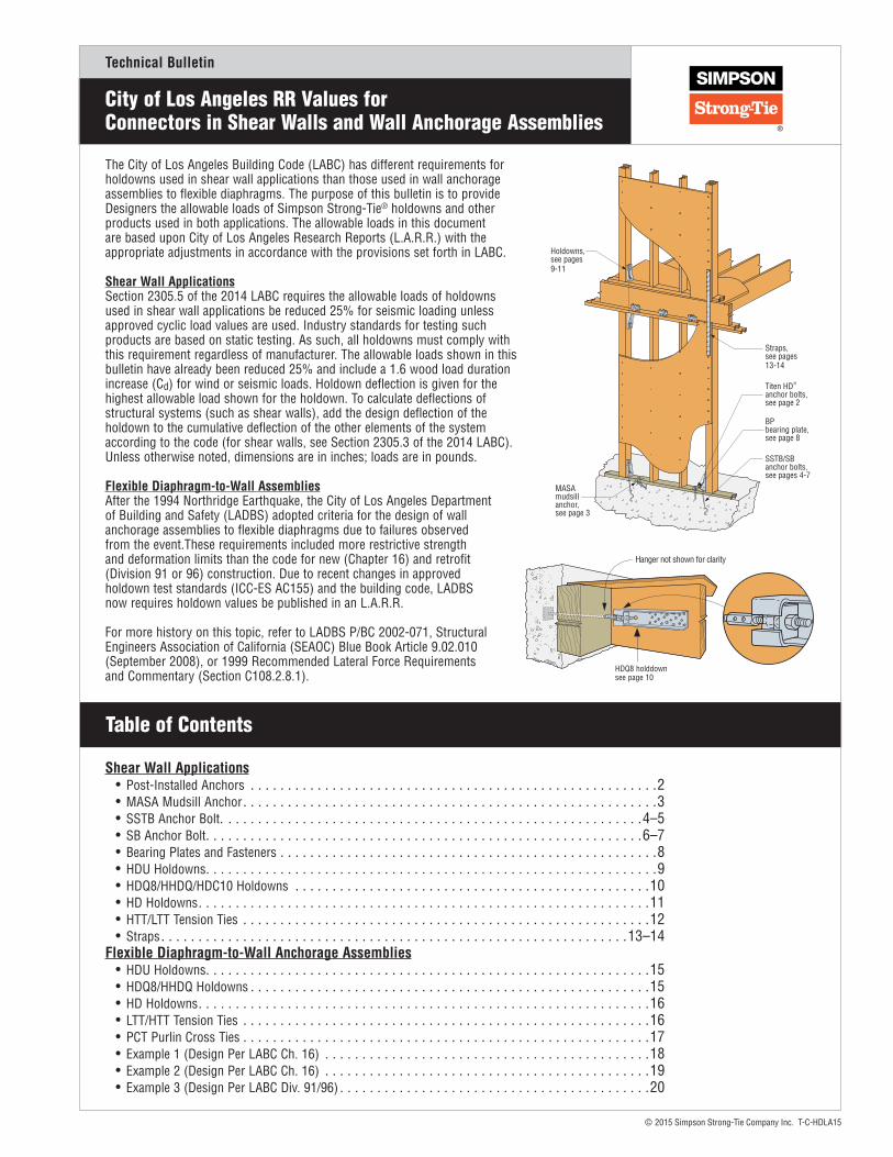
The City of Los Angeles Building Code (LABC) has different requirements for holdowns used in shear wall applications than those used in wall anchorage assemblies to flexible diaphragms. The purpose of this bulletin is to provide Designers the allowable loads of Simpson Strong-Tie® holdowns and other products used in both applications. The allowable loads in this document are based upon City of Los Angeles Research Reports (L.A.R.R.) with the appropriate adjustments in accordance with the provisions set forth in LABC.
Shear Wall ApplicationsSection 2305.5 of the 2014 LABC requires the allowable loads of holdowns used in shear wall applications be reduced 25% for seismic loading unless approved cyclic load values are used. Industry standards for testing such products are based on static testing. As such, all holdowns must comply with this requirement regardless of manufacturer. The allowable loads shown in this bulletin have already been reduced 25% and include a 1.6 wood load duration increase (Cd) for wind or seismic loads. Holdown deflection is given for the highest allowable load shown for the holdown. To calculate deflections of structural systems (such as shear walls), add the design deflection of the holdown to the cumulative deflection of the other elements of the system according to the code (for shear walls, see Section 2305.3 of the 2014 LABC). Unless otherwise noted, dimensions are in inches; loads are in pounds.
Flexible Diaphragm-to-Wall AssembliesAfter the 1994 Northridge Earthquake, the City of Los Angeles Department of Building and Safety (LADBS) adopted criteria for the design of wall anchorage assemblies to flexible diaphragms due to failures observed from the event.These requirements included more restrictive strength and deformation limits than the code for new (Chapter 16) and retrofit (Division 91 or 96) construction. Due to recent changes in approved holdown test standards (ICC-ES AC155) and the building code, LADBS now requires holdown values be published in an L.A.R.R.
For more history on this topic, refer to LADBS P/BC 2002-071, Structural Engineers Association of California (SEAOC) Blue Book Article 9.02.010 (September 2008), or 1999 Recommended Lateral Force Requirements and Commentary (Section C108.2.8.1).
Holdowns, see pages 9-11
Straps, see pages 13-14
SSTB/SB anchor bolts, see pages 4-7
MASA mudsill anchor, see page 3
BP bearing plate, see page 8
Titen HDanchor bolts,see page 2
®
Table of Contents
Shear Wall Applications • Post-Installed Anchors . . . . . . . . . . . . . . . . . . . . . . . . . . . . . . . . . . . . . . . . . . . . . . . . . . . . . . .2 • MASA Mudsill Anchor. . . . . . . . . . . . . . . . . . . . . . . . . . . . . . . . . . . . . . . . . . . . . . . . . . . . . . . .3 • SSTB Anchor Bolt. . . . . . . . . . . . . . . . . . . . . . . . . . . . . . . . . . . . . . . . . . . . . . . . . . . . . . . . .4–5 • SB Anchor Bolt. . . . . . . . . . . . . . . . . . . . . . . . . . . . . . . . . . . . . . . . . . . . . . . . . . . . . . . . . . .6–7 • Bearing Plates and Fasteners . . . . . . . . . . . . . . . . . . . . . . . . . . . . . . . . . . . . . . . . . . . . . . . . . . .8 • HDU Holdowns. . . . . . . . . . . . . . . . . . . . . . . . . . . . . . . . . . . . . . . . . . . . . . . . . . . . . . . . . . . . .9 • HDQ8/HHDQ/HDC10 Holdowns . . . . . . . . . . . . . . . . . . . . . . . . . . . . . . . . . . . . . . . . . . . . . . . .10 • HD Holdowns. . . . . . . . . . . . . . . . . . . . . . . . . . . . . . . . . . . . . . . . . . . . . . . . . . . . . . . . . . . . .11 • HTT/LTT Tension Ties . . . . . . . . . . . . . . . . . . . . . . . . . . . . . . . . . . . . . . . . . . . . . . . . . . . . . . .12 • Straps. . . . . . . . . . . . . . . . . . . . . . . . . . . . . . . . . . . . . . . . . . . . . . . . . . . . . . . . . . . . . . .13–14Flexible Diaphragm-to-Wall Anchorage Assemblies • HDU Holdowns. . . . . . . . . . . . . . . . . . . . . . . . . . . . . . . . . . . . . . . . . . . . . . . . . . . . . . . . . . . .15 • HDQ8/HHDQ Holdowns . . . . . . . . . . . . . . . . . . . . . . . . . . . . . . . . . . . . . . . . . . . . . . . . . . . . . .15 • HD Holdowns. . . . . . . . . . . . . . . . . . . . . . . . . . . . . . . . . . . . . . . . . . . . . . . . . . . . . . . . . . . . .16 • LTT/HTT Tension Ties . . . . . . . . . . . . . . . . . . . . . . . . . . . . . . . . . . . . . . . . . . . . . . . . . . . . . . .16 • PCT Purlin Cross Ties . . . . . . . . . . . . . . . . . . . . . . . . . . . . . . . . . . . . . . . . . . . . . . . . . . . . . . .17 • Example 1 (Design Per LABC Ch. 16) . . . . . . . . . . . . . . . . . . . . . . . . . . . . . . . . . . . . . . . . . . . .18 • Example 2 (Design Per LABC Ch. 16) . . . . . . . . . . . . . . . . . . . . . . . . . . . . . . . . . . . . . . . . . . . .19 • Example 3 (Design Per LABC Div. 91/96) . . . . . . . . . . . . . . . . . . . . . . . . . . . . . . . . . . . . . . . . . .20
Hanger not shown for clarity
HDQ8 holddown see page 10
© 2015 Simpson Strong-Tie Company Inc. T-C-HDLA15

Technical Bulletin
SET-XP® Anchoring Adhesive
SET Anchoring Adhesive
SET-XP is a 1:1 two-component, high-solids, epoxy-based anchoring adhesive formulated for optimum performance in both cracked and uncracked concrete. SET-XP has been rigorously tested in accordance with ICC-ES AC308 as well as 2011 LABC requirements and has proven to offer increased reliability in the most adverse conditions, including performance in cracked concrete under static and seismic loading. When properly mixed, SET-XP is teal in color in order to be identified as a high-performance adhesive for adverse conditions. Resin and hardener are dispensed and mixed simultaneously through the mixing nozzle. SET-XP exceeds the ASTM C881 specification for Type I and Type IV, Grade 3, Class C epoxy.
CODE: City of L.A. RR25744 (Concrete) and RR25966 (Masonry)
SET Epoxy-Tie epoxy is a two-component, 1:1 ratio, high-solids, epoxy-based adhesive for use as a high-strength, non-shrink anchor grouting material. Resin and hardener are dispensed and mixed simultaneously through the mixing nozzle. SET meets or exceeds the ASTM C-881 specification for Type I, II, IV and V, Grade 3, Class B and C.
CODE: City of LA RR25279 (Masonry)
Anchor Designer Software® for ACI 318 Anchor Designer Software® is a professional-strength design application that analyzes and offers anchor solutions using the ACI 318, Appendix D strength design methodology. It provides cracked- and uncracked-concrete anchor solutions for many Simpson Strong-Tie® mechanical and adhesive anchors, such as those shown below.
With its easy-to-use graphical interface, Anchor Designer Software for ACI 318 eliminates the need for tedious calculations by hand that would otherwise be necessary to determine cracked concrete anchor solutions.
To download this free software, go to www.strongtie.com/software.
TITEN HD® Heavy-Duty Screw Anchor
STRONG-BOLT® 2 Wedge Anchor
WEDGE-ALL® Wedge Anchor
The Titen HD is a patented, high-strength screw anchor for concrete and masonry. It is designed for optimum performance in both cracked and uncracked concrete; a requirement that the 2011 LABC places on post-installed anchors. The high-strength, easy-to-install Titen HD anchor has been tested and shown to provide outstanding performance in cracked and uncracked concrete under both static and seismic-loading conditions. The self-undercutting, non-expansion characteristics of the Titen HD anchor make it ideal for structural applications, even at reduced edge distances and spacings. Recommended for permanent application in dry, interior non-corrosive environments or temporary outdoor applications.
CODE: City of L.A. RR25741 (Concrete) and RR25560 (CMU)
The Strong-Bolt® 2 wedge anchor is designed for optimal performance in cracked and uncracked concrete. Following rigorous testing according to ICC-ES acceptance criteria, the Strong-Bolt 2 anchor received classification as a Category 1 anchor, the highest attainable anchor category for performance in cracked concrete under static and seismic loading. Also available in stainless steel, it is code-listed by ICC-ES under the 2012 IBC requirements for post-installed anchors in cracked and uncracked concrete.
CODE: City of L.A. RR25891 (Concrete) and RR25936 (Carbon Steel in CMU)
The Wedge-All anchor is a non-bottom-bearing, wedge-style expansion anchor for use in grout-filled concrete masonry. A one-piece clip ensures uniform holding capacity that increases as tension is applied. The threaded stud version is available in eight diameters and multiple lengths. Threaded studs are set by tightening the nut.
CODE: City of L.A. RR24682 (CMU)
U.S. Patent 5,674,035 and
6,623,228
CrackedConcrete CODE LISTED
Bétonfissuré
CODE ÉNUMÉRÉ
CrackedConcrete CODE LISTED
Bétonfissuré
CODE ÉNUMÉRÉ
CrackedConcrete CODE LISTED
Bétonfissuré
CODE ÉNUMÉRÉ
© 2015 Simpson Strong-Tie Company Inc. T-C-HDLA15 12/15 exp. 12/17
City of Los Angeles RR Listings for Post-Installed Anchors
Page 2 of 20
Technical Bulletin
© 2015 Simpson Strong-Tie Company Inc. T-C-HDLA15
Page 3 of 20
Allowable Stress Design (ASD) Loads for MASA and MASAP Foundation Anchor Straps
Wind and SDC A&B – Allowable Loads (lbs.) 1,2,4,5,6,7,8
Sill SizeFasteners Uncracked Concrete 3 Cracked Concrete 3
Sides Top Uplift F1 F2 Uplift F1 F2STANDARD INSTALLATION
2x4, 2x6 (3) 10dx1 1⁄2 (6) 10dx1 1⁄2 920 1,515 1,095 785 1,515 9103x4, 3x6 (5) 10dx1 1⁄2 (4) 10dx1 1⁄2 650 1,215 725 495 1,215 725
ONE LEG UP INSTALLATION
2x4, 2x6 (6) 10dx1 1⁄2 (3) 10dx1 1⁄2 785 1,005 995 595 1,005 9653x4, 3x6 (7) 10dx1 1⁄2 (2) 10dx1 1⁄2 — 815 — — 815 —
TWO LEGS UP INSTALLATION
2x4, 2x6 3x4, 3x6 (9) 10dx1 1⁄2 — 810 1,150 900 665 1,150 660
DOUBLE 2x SILL INSTALLATION
DBL 2x4, DBL 2x6 (5) 10dx1 1⁄2 (2) 10dx1 1⁄2 875 1,075 785 660 1,075 785SDC C–F – Allowable Loads (lbs.) 1,2,4,5,6,7,8
Sill SizeFasteners Uncracked Concrete 3 Cracked Concrete 3
Sides Top Uplift F1 F2 Uplift F1 F2STANDARD INSTALLATION
2x4, 2x6 (3) 10dx1 1⁄2 (6) 10dx1 1⁄2 745 1,235 1,045 660 1,235 7653x4, 3x6 (5) 10dx1 1⁄2 (4) 10dx1 1⁄2 550 1,020 725 415 1,020 640
ONE LEG UP INSTALLATION
2x4, 2x6 (6) 10dx1 1⁄2 (3) 10dx1 1⁄2 660 845 995 500 845 8103x4, 3x6 (7) 10dx1 1⁄2 (2) 10dx1 1⁄2 — 665 — — 685 —
TWO LEGS UP INSTALLATION
2x4, 2x6 3x4, 3x6 (9) 10dx1 1⁄2 — 740 965 755 560 965 550
DOUBLE 2x SILL INSTALLATION
DBL 2x4, DBL 2x6 (5) 10dx1 1⁄2 (2) 10dx1 1⁄2 735 900 785 555 900 785
For SI: 1 in. = 25.4 mm, 1 lb. = 4.45 N, 1 psi. = 6.895 kPa, 1 plf. = 14.59 N/m.
City of Los Angeles RR ValuesMASA Mudsill Anchors
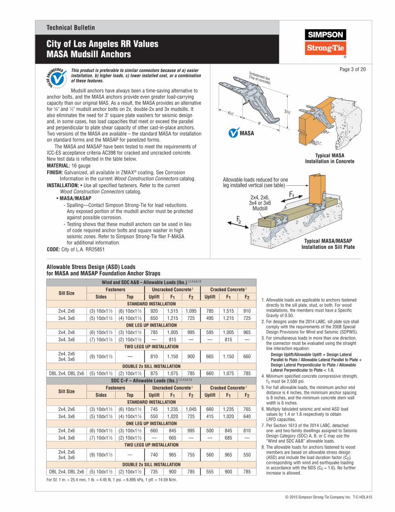
Mudsill anchors have always been a time-saving alternative to anchor bolts, and the MASA anchors provide even greater load-carrying capacity than our original MAS. As a result, the MASA provides an alternative for 5⁄8" and 1⁄2" mudsill anchor bolts on 2x, double-2x and 3x mudsills. It also eliminates the need for 3" square plate washers for seismic design and, in some cases, has load capacities that meet or exceed the parallel and perpendicular to plate shear capacity of other cast-in-place anchors. Two versions of the MASA are available – the standard MASA for installation on standard forms and the MASAP for panelized forms.
The MASA and MASAP have been tested to meet the requirements of ICC-ES acceptance criteria AC398 for cracked and uncracked concrete. New test data is reflected in the table below.MATERIAL: 16 gaugeFINISH: Galvanized, all available in ZMAX® coating. See Corrosion Information in the current Wood Construction Connectors catalog.INSTALLATION: • Use all specified fasteners. Refer to the current Wood Construction Connectors catalog.
• MASA/MASAP - Spalling—Contact Simpson Strong-Tie for load reductions.
Any exposed portion of the mudsill anchor must be protected against possible corrosion.
- Testing shows that these mudsill anchors can be used in lieu of code required anchor bolts and square washer in high seismic zones. Refer to Simpson Strong-Tie flier F-MASA for additional information.
CODE: City of L.A. RR25851
Typical MASA Installation in Concrete
Allowable loads reduced for one leg installed vertical (see table)
2x4, 2x6,3x4 or 3x6
Mudsill
Typical MASA/MASAP Installation on Sill Plate
This product is preferable to similar connectors because of a) easier installation, b) higher loads, c) lower installed cost, or a combination of these features.
33⁄8"
4"
Embedment line(Top of concrete)
41⁄4"
MASA
1. Allowable loads are applicable to anchors fastened directly to the sill plate, stud, or both. For wood installations, the members must have a Specific Gravity of 0.50.
2. For designs under the 2014 LABC, sill plate size shall comply with the requirements of the 2008 Special Design Provisions for Wind and Seismic (SDPWS).
3. For simultaneous loads in more than one direction, the connector must be evaluated using the straight line interaction equation:
Design Uplift/Allowable Uplift + Design Lateral Parallel to Plate / Allowable Lateral Parallel to Plate + Design Lateral Perpendicular to Plate / Allowable Lateral Perpendicular to Plate < 1.0.
4. Minimum specified concrete compressive strength, f'c must be 2,500 psi.
5. For full allowable loads, the minimum anchor end distance is 4 inches, the minimum anchor spacing is 8 inches, and the minimum concrete stem wall width is 6 inches.
6. Multiply tabulated seismic and wind ASD load values by 1.4 or 1.6 respectively to obtain LRFD capacities.
7. Per Section 1613 of the 2014 LABC, detached one- and two-family dwellings assigned to Seismic Design Category (SDC) A, B, or C may use the “Wind and SDC A&B” allowable loads.
8. The allowable loads for anchors fastened to wood members are based on allowable stress design (ASD) and include the load duration factor (CD) corresponding with wind and earthquake loading in accordance with the NDS (CD = 1.6). No further increase is allowed.

Technical Bulletin
© 2015 Simpson Strong-Tie Company Inc. T-C-HDLA15
Page 4 of 20The SSTB anchor bolt is designed for maximum performance as an anchor bolt for
holdowns and Simpson Strong-Tie® Strong-Wall® shearwalls. Extensive testing has been done to determine the design load capacity of the SSTB when installed in many common applications.
The SSTB anchor bolt is code-listed by ICC-ES under the 2012 IBC® and IRC® to meet the requirements of ICC-ES acceptance criteria (AC) 399. ICC-ES ESR-2611 is the industry’s first code report issued for proprietary anchor bolts evaluated to the criteria of AC399. Special Features:
• Identification on the bolt head showing embedment angle and model• Offset angle reduces side bursting and provides more concrete cover• Rolled thread for higher tensile capacity• Stamped embedment line aids installation• Available with a hot-dipped galvanized (HDG) finish for additional corrosion
resistanceMATERIAL: ASTM F-1554, Grade 36FINISH: None. May be ordered HDG; contact Simpson Strong-Tie.INSTALLATION:
• SSTB is suitable for monolithic and two-pour concrete applications.• Nuts and washers for holdown attachment are not supplied with the
SSTB; install standard nuts, couplers and/or washers as required.• On HDG SSTB anchors, chase the threads to use standard nuts or
couplers or use overtapped products in accordance with ASTM A563, for example Simpson Strong-Tie® NUT5⁄8-OST or NUT7⁄8-OST.
• Install SSTB before the concrete pour using Simpson Strong-Tie AnchorMate® anchor bolt holders.Install the SSTB per the plan view detail.
• Minimum concrete compressive strength is 2,500 psi.• When rebar is required it does not need to be tied to the SSTB.• Order SSTBL Models (example: SSTB16L) for longer thread length
(16L = 5 1⁄2", 20L = 6 1⁄2", 24L = 6", 28L = 6 1⁄2"). SSTB and SSTBL load values are the same. SSTB34 and SSTB36 feature 4 1⁄2" and 6 1⁄2" of thread, respectively, and are not available in “L” versions.
CODE: City of L.A. RR25827
SSTB16(others similar)U.S. Patent 5,317,850
CornerInstallation
(Install with arrowon top of the bolt
oriented as shown)
CornerInstallation
(Install with arrowon top of the bolt
oriented as shown)
Non-CornerInstallation
(Bolt may beinstalled @ 45° to135° as shown)
Outer Edge of Concrete (Typ.)
Anchor Bolt(Typ.)
Plan View of SSTB Placement in Concrete
Perspective View
Corner Midwall Endwall
#4 rebar3"-5" from top
1. SSTB28, SSTB34 and SSTB36 with 3 7⁄8" end distance allowable loads are 6,605 lbs. (Wind) and 5,550 lbs. (SDC C-F).
SSTB Bolts at Stemwall
Model No.
Dimensions Allowable Tension Loads (lbs.)
Stemwall Width(in.)
Dia.(in.)
Length(in.)
Min. Embed.
(le)
Wind SDC C–F
Midwall Corner End-of-Wall1 Midwall Corner End-of-Wall1
SSTB16 6 5⁄8 17 5⁄8 (16L = 19 5⁄8) 12 5⁄8 3,610 3,610 3,610 2,550 2,550 2,550SSTB20 6 5⁄8 21 5⁄8 (20L = 24 5⁄8) 16 5⁄8 4,315 4,040 4,040 3,145 2,960 2,960SSTB24 6 5⁄8 25 5⁄8 (24L = 28 1⁄8) 20 5⁄8 5,025 4,470 4,470 3,740 3,325 3,325SSTB28 8 7⁄8 29 7⁄8 (28L = 32 7⁄8) 24 7⁄8 9,900 8,710 7,615 8,315 7,315 6,395SSTB34 8 7⁄8 34 7⁄8 28 7⁄8 9,900 8,710 7,615 8,315 7,315 6,395SSTB36 8 7⁄8 36 7⁄8 28 7⁄8 9,900 8,710 7,615 8,315 7,315 6,395
Min
. reb
ar le
ngth
or to
end
of w
all2
x l e
1.5
l e M
in.
2 x
l e
13⁄4" Min.
Locateapprox. 45°
to 90°from wall
#4 Rebar
Midwall
Place SB arrowdiagonal in cornerapplication
16" Min. return 2x l e
min
. reb
ar le
ngth
13/4" Min.
5"
Corner
STEMWALL PLAN VIEWS
End-Of-Wall
Min
. reb
ar le
ngth
2 x
l e
13/4" Min.
5"
City of Los Angeles RR ValuesSSTB Anchor Bolt
Technical Bulletin
© 2015 Simpson Strong-Tie Company Inc. T-C-HDLA15
Page 5 of 20
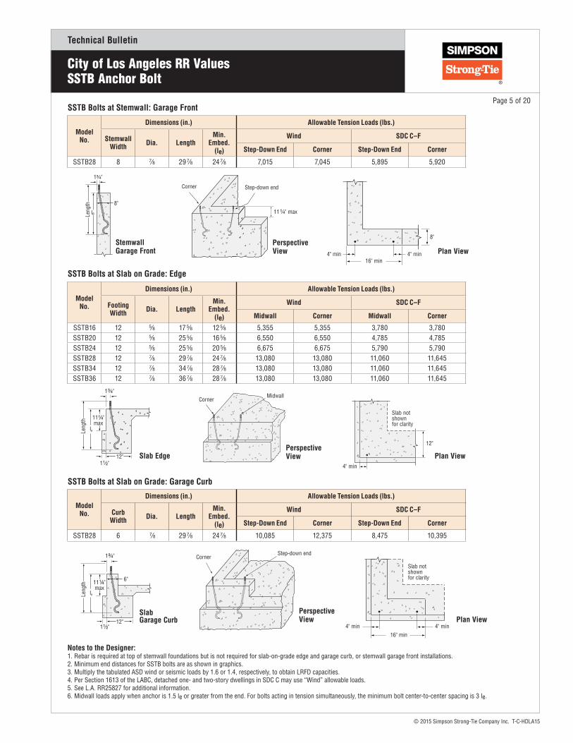
Notes to the Designer:1. Rebar is required at top of stemwall foundations but is not required for slab-on-grade edge and garage curb, or stemwall garage front installations.2. Minimum end distances for SSTB bolts are as shown in graphics. 3. Multiply the tabulated ASD wind or seismic loads by 1.6 or 1.4, respectively, to obtain LRFD capacities.4. Per Section 1613 of the LABC, detached one- and two-story dwellings in SDC C may use “Wind” allowable loads.5. See L.A. RR25827 for additional information.6. Midwall loads apply when anchor is 1.5 le or greater from the end. For bolts acting in tension simultaneously, the minimum bolt center-to-center spacing is 3 le.
Model No.
Dimensions (in.) Allowable Tension Loads (lbs.)
Curb Width Dia. Length
Min. Embed.
(le)
Wind SDC C–F
Step-Down End Corner Step-Down End Corner
SSTB28 6 7⁄8 29 7⁄8 24 7⁄8 10,085 12,375 8,475 10,395
SSTB Bolts at Slab on Grade: Garage Curb
Model No.
Dimensions (in.) Allowable Tension Loads (lbs.)
Footing Width Dia. Length
Min. Embed.
(le)
Wind SDC C–F
Midwall Corner Midwall Corner
SSTB16 12 5⁄8 17 5⁄8 12 5⁄8 5,355 5,355 3,780 3,780SSTB20 12 5⁄8 25 5⁄8 16 5⁄8 6,550 6,550 4,785 4,785SSTB24 12 5⁄8 25 5⁄8 20 5⁄8 6,675 6,675 5,790 5,790SSTB28 12 7⁄8 29 7⁄8 24 7⁄8 13,080 13,080 11,060 11,645SSTB34 12 7⁄8 34 7⁄8 28 7⁄8 13,080 13,080 11,060 11,645SSTB36 12 7⁄8 36 7⁄8 28 7⁄8 13,080 13,080 11,060 11,645
SSTB Bolts at Slab on Grade: Edge
Model No.
Dimensions (in.) Allowable Tension Loads (lbs.)
Stemwall Width Dia. Length
Min. Embed.
(le)
Wind SDC C–F
Step-Down End Corner Step-Down End Corner
SSTB28 8 7⁄8 29 7⁄8 24 7⁄8 7,015 7,045 5,895 5,920
SSTB Bolts at Stemwall: Garage Front
City of Los Angeles RR ValuesSSTB Anchor Bolt
Perspective View
CornerMidwall
Plan View4" min
12"
Slab not shown for clarity
Slab Edge
Leng
th
le
12" 1 1⁄2"
1 3⁄4"
11 1⁄4"max
Perspective View
CornerStep-down end
SlabGarage Curb
Leng
th
le
11 1⁄4"max
1 3⁄4"
6"
12"1 1⁄2"
Plan View
Slab not shown for clarity
16" min4" min4" min
Perspective View
Corner Step-down end
11 1⁄4" max
Plan View16" min
4" min4" min
8" StemwallGarage Front
8"
leLeng
th
13/4"

Technical Bulletin
© 2015 Simpson Strong-Tie Company Inc. T-C-HDLA15
Page 6 of 20The 5⁄8"x24" SB anchor bolt offers a load-tested anchorage solution that exceeds the
capacity of all of our holdowns that call for a 5⁄8" dia. anchor. Similarly, the 1"x30" SB anchor bolt covers holdowns utilizing a 1" diameter anchor that exceed the capacity of our SSTB bolts. The 7⁄8"x24" SB anchor bolt is designed to maximize performance with minimum embedment for holdowns utilizing a 7⁄8" diameter anchor.
SB anchor bolts are code listed by ICC-ES under the 2012 IBC® and IRC® to meet the requirements of ICC-ES acceptance criteria AC399. ICC-ES ESR-2611 is the industry’s first code report issued for proprietary anchor bolts evaluated to the criteria of AC399.Special Features:
• Indentification on the bolt head showing embedment angle and model• Sweep geometry to optimize position in form• Rolled thread for higher tensile capacity• Hex nuts and plate washer fixed in position• Available with a hot-dipped galvanized (HDG) finish for
additional corrosion resistanceMATERIAL: ASTM F-1554, Grade 36FINISH: None. May be ordered HDG. Contact Simpson Strong-Tie. INSTALLATION:
• SB is only for concrete applications poured monolithically.• Top nuts and washers for holdown attachment are not supplied with the SB;
install standard nuts, couplers and/or washers as required.• On HDG SB anchors, chase the threads to use standard nuts or couplers
or use overtapped products in accordance with ASTM A563, for example Simpson Strong-Tie® NUT5⁄8-OST, NUT7⁄8-OST and NUT1-OST.
• Install SB before the concrete pour using Simpson Strong-Tie AnchorMates®
anchor bolt holders. Install the SB per the plan view detail.• Minimum concrete compressive strength is 2,500 psi.• When rebar is required it does not need to be tied to the SB.
CODE: City of L.A. RR25827
EmbedmentLine (Top ofConcrete)
Leng
th
30
le
6"(standard onall models)
SB1x30(Other models similar)
Embedment Line(Top of concrete)
1³⁄₄" Min.Edge Distance
3" to 5"
#4 rebar (may be foundation rebar)
Footing W
Typical SB Installation
CornerInstallation
(Install with arrowon top of the bolt
oriented as shown)
CornerInstallation
(Install with arrowon top of the bolt
oriented as shown)
Non-CornerInstallation
(Bolt may beinstalled @ 45° to135° as shown)
Outer Edge of Concrete (Typ.)
Anchor Bolt(Typ.)24
2424
Plan View of SB Placement in Concrete
Model No.
Dimensions (in.) Allowable Tension Loads (lbs.)
Stemwall Width Dia. Length Min.
Embed. (le)
Wind SDC C–F
Midwall Corner End-of-Wall Midwall Corner End-of-Wall
SB5⁄8x24 6 5⁄8 24 18 6,675 6,675 6,675 6,675 5,730 5,730
SB7⁄8x24 8 7⁄8 24 18 10,470 9,355 6,820 8,795 7,855 5,730
SB1x30 8 1 30 24 13,665 9,905 7,220 11,470 8,315 6,065
Perspective View
Corner Midwall Endwall
#4 rebar3"-5" from top
End-Of-Wall1³⁄₄" Min.
4¹⁄₄" Min. (SB ⅝ and ⅞)5" Min. (SB1)
reba
r len
gth
2 x
l e m
in.
Midwall
Min
. reb
ar le
ngth
2 x
l e2
x l e
1³⁄₄" Min.
Locateapprox. 45°
to 90°from wall
#4 RebarPlace SB arrowdiagonal in cornerapplication
16" Min. return 2x l e
min
. reb
ar le
ngth
13/4" Min.
4¼" Min. (SB5/8 and 7/8)5" Min. (SB1)
CornerSTEMWALL PLAN VIEWS
SB Bolts at Stemwall
City of Los Angeles RR Values SB Anchor Bolt

Technical Bulletin
© 2015 Simpson Strong-Tie Company Inc. T-C-HDLA15
Page 7 of 20
Notes to the Designer:1. Rebar is required at top of stemwall foundations but is not required for slab-on-grade edge and garage curb, or stemwall garage front installations.2. Minimum end distances for SB bolts are as shown in graphics. 3. Multiply the tabulated ASD wind or seismic loads by 1.6 or 1.4, respectively, to obtain LRFD capacities.4. Per Section 1613 of the LABC, detached one- and two-story dwellings in SDC C may use “Wind” allowable loads.5. See L.A. RR25827 for additional information.6. Midwall loads apply when anchor is 1.5 le or greater from the end. For bolts acting in tension simultaneously, the minimum bolt center-to-center spacing is 3 le.
Model No.
Dimensions (in.) Allowable Tension Loads (lbs.)
Stemwall Width Dia. Length
Min. Embed.
(le)
Wind SDC C–F
Step-Down End Corner Step-Down End Corner
SB7⁄8x24 8 7⁄8 24 18 7,225 7,660 6,070 6,435
SB1x30 8 1 30 24 11,305 9,635 9,495 8,030
SB Bolts at Stemwall: Garage Front
Model No.
Dimensions (in.) Allowable Tension Loads (lbs.)
Footing Width Dia. Length
Min. Embed.
(le)
Wind SDC C–F
Midwall Corner Midwall Corner
SB5⁄8x24 12 5⁄8 24 18 6,675 6,675 6,675 5,730
SB7⁄8x24 12 7⁄8 24 18 13,080 12,135 12,320 10,190
SB1x30 12 1 30 24 17,080 15,580 16,300 13,090
SB Bolts at Slab on Grade: Edge
Model No.
Dimensions (in.) Allowable Tension Loads (lbs.)
Curb Width Dia. Length
Min. Embed.
(le)
Wind SDC C–F
Step-Down End Corner Step-down End Corner
SB7⁄8x24 6 7⁄8 24 18 9,175 11,075 7,705 9,305
SB1x30 6 1 30 24 15,580 15,580 13,090 13,090
SB Bolts at Slab on Grade: Garage Curb
Perspective View
Corner Step-down end
11¼" max8"
1¾"
leLeng
th
StemwallGarage Front
4" min (SB⁷⁄₈)3" min(SB1)
4" min (SB⁷⁄₈)3" min (SB1)
16" min (SB⁷⁄₈)12" min (SB1)
8"
Plan View
1¾"
1½"
11¼"max.
12"
Leng
th
le
Slab Edge
CornerMidwall
Perspective View
Corner
Step-down end
Perspective View
6"
1¾"
1½"12"
11¼"max.
Leng
th
le
SlabGarage Curb
Slab not shown for clarity
16" min (SB⁷⁄₈)12" min (SB1)
4" min (SB⁷⁄₈)3" min(SB1)
4" min (SB⁷⁄₈)3" min (SB1)
Plan View
City of Los Angeles RR Values SB Anchor Bolt
Plan View
4" min (SB5⁄8 and 7⁄8)3" min (SB1)
Corner Midwall 12"
Slab not shown for clarity
1.5 le
Technical Bulletin
© 2015 Simpson Strong-Tie Company Inc. T-C-HDLA15
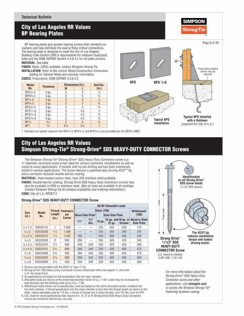
BP bearing plates give greater bearing surface than standard cut washers and help distribute the load at these critical connections. The bearing plate is designed to meet the City of Los Angeles Building Code Section 2305.5 requirements for holdown studs/post bolts and the 2008 SDPWS Section 4.3.6.4.3 for sill plate anchors.MATERIAL: See tableFINISH: None. (HDG) available, contact Simpson Strong-Tie.INSTALLATION: Refer to the current Wood Construction Connectors catalog for General Notes and warranty information.CODES: Prescriptive; 2008 SDPWS 4.3.6.4.3
City of Los Angeles RR ValuesSimpson Strong-Tie® Strong-Drive® SDS HEAVY-DUTY CONNECTOR Screws
Page 8 of 20
Typical BPS Installed with a Holdown
(required for City of L.A.)
BP
Preservative-treatedbarrier may be
required.
The Simpson Strong-Tie® Strong-Drive® SDS Heavy-Duty Connector screw is a 1⁄4"-diameter structural wood screw ideal for various connector installations as well as wood-to-wood applications. It installs with no pre-drilling and has been extensively tested in various applications. The screw features a patented easy driving 4CUT™ tip and a corrosion resistant double-barrier coating. MATERIAL: Heat-treated carbon steel, type-316 stainless steel availableFINISH: Double-barrier coating. Strong-Drive SDS Heavy-Duty Connector screws may also be available in HDG or stainless steel. (Not all sizes are available in all coatings. Contact Simpson Strong-Tie for product availability and ordering information.)CODE: City of L.A. RR25711
The 4CUT tip reduces installation torque and makes
driving easier.
Thre
ad L
engt
h
Leng
th
Thread Length
Length
Identification on all Strong-Drive®
SDS screw heads(1⁄4"x3" SDS shown)
Strong-Drive®
1⁄4"x3" SDSHEAVY-DUTY
CONNECTOR Screw U.S. Patent 6,109,850;5,897,280; 7,101,133
Strong-Drive® SDS HEAVY-DUTY CONNECTOR Screw
Size (in.)
Model No.
Thread Length
(in.)
Fasteners per
Carton
DF/SP Allowable LoadsShear (100) Withdrawal5
(100)Wood Side Plate3 Steel Side Plate
1 1⁄2" 1 3⁄4" SCL 16 ga. 14 ga. and
12 ga.10 ga. or Greater
Wood or Steel Side Plate
1⁄4 x 1 1⁄2 SDS25112 1 1,500 — — 250 250 250 1701⁄4 x 2 SDS25200 1 1⁄4 1,300 — — 250 290 290 215
1⁄4 x 2 1⁄2 SDS25212 1 1⁄2 1,100 190 — 250 390 420 2551⁄4 x 3 SDS25300 2 950 280 — 250 420 420 345
1⁄4 x 3 1⁄2 SDS25312 2 1⁄4 900 340 340 250 420 420 3851⁄4 x 4 1⁄2 SDS25412 2 3⁄4 800 350 340 250 420 420 475
1⁄4 x 5 SDS25500 2 3⁄4 500 350 340 250 420 420 4751⁄4 x 6 SDS25600 3 1⁄4 600 350 340 250 420 420 5601⁄4 x 8 SDS25800 3 1⁄4 400 350 340 250 420 420 560
1. Screws may be provided with the 4CUT or Type 17 tip.2. Strong-Drive® SDS Heavy-Duty Connector screws install best with a low speed 1⁄2" drill with a 3⁄8" hex head driver. 3. All applications are based on full penetration into the main member. 4. Allowable loads are shown at the wood load duration factor of CD = 1.00. Loads may be increased for load duration per the building code up to a CD = 1.60.5. Withdrawal loads shown are in pounds (lbs.) and are based on the entire threaded section installed into the main member. If thread penetration into the main member is less than the thread length as shown in the table, reduce allowable load by 172 lbs. x inches of thread not in main member. Use 121 lbs./inch for SPF.6. LSL wood-to-wood applications that require 4 1⁄2", 5", 6" or 8" Strong-Drive SDS Heavy-Duty Connector screws are limited to interior-dry use only.
BPSModel
No. ThicknessDimensions (in.) Bolt Dia.
(in.)W LBPS1⁄2-3 3 ga. 3 3 1⁄2BPS5⁄8-3 3 ga. 3 3 5⁄8BP1⁄2-3 3 ga. 3 3 1⁄2BP5⁄8-3 3 ga. 3 3 5⁄8BPS3⁄4-3 3 ga. 3 3 3⁄4BPS1⁄2-6 3 ga. 3 4.5 1⁄2BPS5⁄8-6 3 ga. 3 4.5 5⁄8BPS3⁄4-6 3 ga. 3 4.5 3⁄4BP7⁄8 5⁄16" 3 3 7⁄8BP1 3⁄8" 3 1⁄2 3 1⁄2 1
1. Standard cut washer required with BPS1⁄2-3, BPS5⁄8-3, and BPS3⁄4-3 (not provided) per the 2014 LABC.
Typical BPSInstallation
For more information about the Strong-Drive® SDS Heavy-Duty Connector screw and other applications, visit strongtie.com or access the Simpson Strong-Tie® Fastening Systems catalog.
City of Los Angeles RR Values BP Bearing Plates
BPS 1⁄2-6

Technical Bulletin
© 2015 Simpson Strong-Tie Company Inc. T-C-HDLA15
Page 9 of 20
City of Los Angeles RR ValuesHDU Holdowns in Shear Walls
HDU holdowns are pre-deflected during the manufacturing process, virtually eliminating deflection under load due to material stretch. They use Simpson Strong-Tie® Strong-Drive® SDS Heavy-Duty Connector screws, which install easily and provide reduced fastener slip. Using SDS screws typically results in a greater net section when compared to bolts.
The DTT2Z tension tie is suitable for lighter-duty holdown applications on single or double 2x posts, and installs easily with Strong-Drive SDS screws (included).
For more information on holdown options, contact Simpson Strong-Tie.HDU SPECIAL FEATURES:
• Pre-deflected body virtually eliminates deflection due to material stretch.• Uses SDS screws which install easily, reduce fastener slip, and typically
results in a greater net section area of the post compared to bolts.• Strong-Drive SDS Heavy-Duty Connector screws are supplied with
the holdowns to ensure proper fasteners are used.• No stud bolts to countersink at openings.
MATERIAL: See table FINISH: HDU – Galvanized; DTT2Z – ZMAX® coating or stainless steelINSTALLATION: • Use all specified fasteners. See the current Wood Construction Connectors catalog.
• For use in vertical and horizontal applications.• The HDU requires no additional washer, the DTT2Z requires a standard
cut washer (included) be installed between the nut and the seat. • To tie multiple 2x members together, the Designer must determine the
fasteners required to join the members without splitting the wood. See page 8 for Strong-Drive SDS Heavy-Duty Connector screws values.
• See SB and SSTB anchor bolts on pages 4–7 for anchorage options.• SDS screws install best with a low-speed, high-torque drill with a
3⁄8" hex-head driver.• Anchor bolt nut should be finger tight plus 1⁄3 to 1⁄2 turn with a hand
wrench, with consideration given to possible future wood shrinkage. Care should be taken not to over-tighten the nut. Impact wrenches should not be used.
CODE: City of L.A. RR 25720
Preservative-treatedbarrier may be
required
Post size byDesigner
Minimum woodmember thickness
Vertical HDU Installation
VerticalWood
MemberThickness
Studs/Post
FloorJoist
2 - 2xBlocking
ThreadedRod
Typical HDU Tie Between Floors
Pilot Holes for
ManufacturingPurposes(Fastener
not required)
SO
HDUU.S. Patent 6,112,495
1⁵⁄₈"1⁵⁄₈"
3¹⁄₄"
6¹⁵⁄₁₆"
DTT2
ModelNo. Ga.
Dimensions (in.) Fasteners Minimum Wood Member
Thickness3
(in.)
Allowable Tension Loads (lbs.) (160)
W H B CL SOAnchor
Bolt Dia. (in.)
Strong-Drive® SDS Screws DF/SP
Deflection at Allowable Load5
(in.)
DTT2Z 14 3 1⁄4 6 15⁄16 1 5⁄8 13⁄16 3⁄16 1⁄2 (8) 1⁄4"x1 1⁄2" SDS1 1⁄2 1,370 0.0793 1,610 0.096
HDU214 3 8 11⁄16 3 1⁄4 15⁄16 1 3⁄8 5⁄8
(6) 1⁄4"x1 1⁄2" SDS 3 1,360 0.052HDU2-SDS2.5 (6) 1⁄4"x2 1⁄2" SDS 3 2,305 0.066HDU4
14 3 10 15⁄16 3 1⁄4 15⁄16 1 3⁄8 5⁄8(10) 1⁄4"x1 1⁄2" SDS 3 2,330 0.062
HDU4-SDS2.5 (10) 1⁄4"x2 1⁄2" SDS 3 3,425 0.086HDU5
14 3 13 3⁄16 3 1⁄4 15⁄16 1 3⁄8 5⁄8(14) 1⁄4"x1 1⁄2" SDS 3 2,970 0.082
HDU5-SDS2.5 (14) 1⁄4"x2 1⁄2" SDS3 4,235 0.086
3 1⁄2 4,255 0.086HDU8
10 3 16 5⁄8 3 1⁄2 1 3⁄8 1 1⁄2 7⁄8
(20) 1⁄4"x1 1⁄2" SDS 3 4,485 0.065
HDU8-SDS2.5 (20) 1⁄4"x2 1⁄2" SDS3 4,485 0.065
3 1⁄2 5,230 0.0764 1⁄2 5,905 0.086
HDU11-SDS2.5 10 3 22 1⁄4 3 1⁄2 1 3⁄8 1 1⁄2 1 (30) 1⁄4"x2 1⁄2" SDS5 1⁄2 7,150 0.0887 1⁄4 8,380 0.103
HDU14-SDS2.5 7 3 25 11⁄16 3 1⁄2 1 9⁄16 1 9⁄16 1 (36) 1⁄4"x2 1⁄2" SDS7 1⁄4 10,7954
0.1295 1⁄2 x 5 1⁄2 10,8354
1. Allowable loads have been increased for earthquake or wind load durations with no further increase allowed; reduce where other load durations govern. 2. The Designer must specify anchor bolt type, length and embedment. See SB and SSTB Anchor bolts (pages 4–7). 3. Post design by Specifier. Allowable loads are based on a minimum 3 1⁄2" wide post except as noted. Post may consist of multiple members provided they are connected independently of the holdown fasteners. 4. Requires heavy hex anchor nut to achieve tabulated loads (supplied with holdown). 5. Deflection includes fastener slip, holdown deformation and anchor rod elongation for holdowns installed up to 6" above top of concrete. Holdowns may be installed raised up to 18" above top of concrete with no load reduction provided additional elongation is accounted for (an additional 0.010" is conservative).
See Pages 15-17 for Wall Anchorage Assemblies
HDU/DTT Holdowns for Use in Shearwall Applications (Loads have been reduced 25% per Section 2305.5 of 2014 LABC)
Technical Bulletin
© 2015 Simpson Strong-Tie Company Inc. T-C-HDLA15
City of Los Angeles RR Values HDQ8, HHDQ and HDC10 Holdowns in Shear Walls
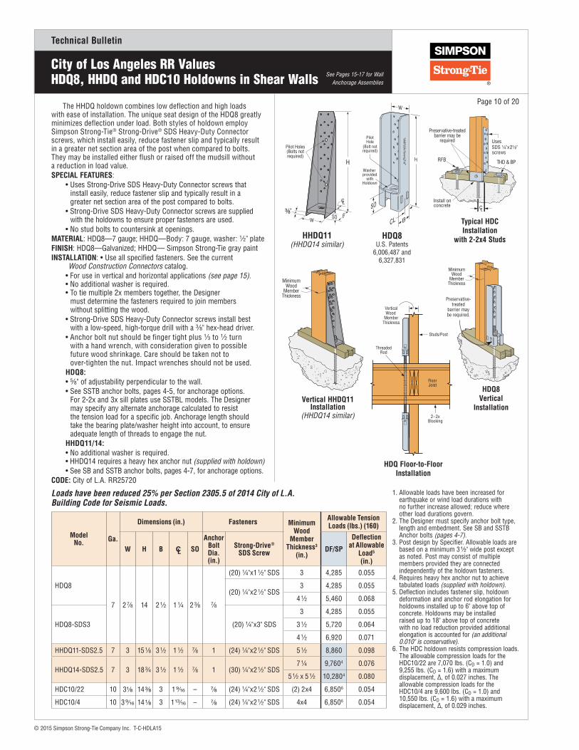
The HHDQ holdown combines low deflection and high loads with ease of installation. The unique seat design of the HDQ8 greatly minimizes deflection under load. Both styles of holdown employ Simpson Strong-Tie® Strong-Drive® SDS Heavy-Duty Connector screws, which install easily, reduce fastener slip and typically result in a greater net section area of the post when compared to bolts. They may be installed either flush or raised off the mudsill without a reduction in load value.SPECIAL FEATURES:
• Uses Strong-Drive SDS Heavy-Duty Connector screws that install easily, reduce fastener slip and typically result in a greater net section area of the post compared to bolts.
• Strong-Drive SDS Heavy-Duty Connector screws are supplied with the holdowns to ensure proper fasteners are used.
• No stud bolts to countersink at openings.MATERIAL: HDQ8—7 gauge; HHDQ—Body: 7 gauge, washer: 1⁄2" plate FINISH: HDQ8—Galvanized; HHDQ— Simpson Strong-Tie gray paintINSTALLATION: • Use all specified fasteners. See the current Wood Construction Connectors catalog.
• For use in vertical and horizontal applications (see page 15).• No additional washer is required.• To tie multiple 2x members together, the Designer
must determine the fasteners required to join members without splitting the wood.
• Strong-Drive SDS Heavy-Duty Connector screws install best with a low-speed, high-torque drill with a 3⁄8" hex-head driver.
• Anchor bolt nut should be finger tight plus 1⁄3 to 1⁄2 turn with a hand wrench, with consideration given to possible future wood shrinkage. Care should be taken not to over-tighten the nut. Impact wrenches should not be used.
HDQ8:• 5⁄8" of adjustability perpendicular to the wall.• See SSTB anchor bolts, pages 4-5, for anchorage options.
For 2-2x and 3x sill plates use SSTBL models. The Designer may specify any alternate anchorage calculated to resist the tension load for a specific job. Anchorage length should take the bearing plate/washer height into account, to ensure adequate length of threads to engage the nut.
HHDQ11/14:• No additional washer is required.• HHDQ14 requires a heavy hex anchor nut (supplied with holdown)• See SB and SSTB anchor bolts, pages 4-7, for anchorage options.
CODE: City of L.A. RR25720
Page 10 of 20
See Pages 15-17 for Wall Anchorage Assemblies
MinimumWood
MemberThickness
Vertical HHDQ11 Installation
(HHDQ14 similar)
SO
HDQ8U.S. Patents
6,006,487 and 6,327,831
MinimumWood
MemberThickness
HDQ8 Vertical
Installation
Preservative- treated
barrier may be required.
ModelNo. Ga.
Dimensions (in.) Fasteners Minimum Wood
Member Thickness3
(in.)
Allowable Tension Loads (lbs.) (160)
W H B CL SO
Anchor Bolt Dia. (in.)
Strong-Drive® SDS Screw DF/SP
Deflection at Allowable
Load5
(in.)
HDQ8
7 2 7⁄8 14 2 1⁄2 1 1⁄4 2 3⁄8 7⁄8
(20) 1⁄4"x1 1⁄2" SDS 3 4,285 0.055
(20) 1⁄4"x2 1⁄2" SDS3 4,285 0.055
4 1⁄2 5,460 0.068
HDQ8-SDS3 (20) 1⁄4"x3" SDS
3 4,285 0.055
3 1⁄2 5,720 0.064
4 1⁄2 6,920 0.071
HHDQ11-SDS2.5 7 3 15 1⁄8 3 1⁄2 1 1⁄2 7⁄8 1 (24) 1⁄4"x2 1⁄2" SDS 5 1⁄2 8,860 0.098
HHDQ14-SDS2.5 7 3 18 3⁄4 3 1⁄2 1 1⁄2 7⁄8 1 (30) 1⁄4"x2 1⁄2" SDS7 1⁄4 9,7604 0.076
5 1⁄2 x 5 1⁄2 10,2804 0.080
HDC10/22 10 3⅛ 14 ⅜ 3 1 9⁄16 – ⅞ (24) 1⁄4"x2 1⁄2" SDS (2) 2x4 6,8506 0.054
HDC10/4 10 3 9⁄16 14 ⅛ 3 1 13⁄16 – ⅞ (24) 1⁄4"x2 1⁄2" SDS 4x4 6,8506 0.054
1. Allowable loads have been increased for earthquake or wind load durations with no further increase allowed; reduce where other load durations govern.2. The Designer must specify anchor bolt type, length and embedment. See SB and SSTB Anchor bolts (pages 4-7). 3. Post design by Specifier. Allowable loads are based on a minimum 3 1⁄2" wide post except as noted. Post may consist of multiple members provided they are connected independently of the holdown fasteners.4. Requires heavy hex anchor nut to achieve tabulated loads (supplied with holdown).5. Deflection includes fastener slip, holdown deformation and anchor rod elongation for holdowns installed up to 6" above top of concrete. Holdowns may be installed raised up to 18" above top of concrete with no load reduction provided additional elongation is accounted for (an additional 0.010" is conservative).6. The HDC holdown resists compression loads. The allowable compression loads for the HDC10/22 are 7,070 lbs. (CD = 1.0) and 9,255 lbs. (CD = 1.6) with a maximum displacement, Δ, of 0.027 inches. The allowable compression loads for the HDC10/4 are 9,600 lbs. (CD = 1.0) and 10,550 lbs. (CD = 1.6) with a maximum displacement, Δ, of 0.029 inches.
Loads have been reduced 25% per Section 2305.5 of 2014 City of L.A. Building Code for Seismic Loads.
SO
HHDQ11(HHDQ14 similar)
VerticalWood
MemberThickness
Studs/Post
FloorJoist
2 – 2xBlocking
ThreadedRod
HDQ Floor-to-Floor Installation
Preservative-treatedbarrier may be
required
Typical HDC Installation
with 2-2x4 Studs

Technical Bulletin
© 2015 Simpson Strong-Tie Company Inc. T-C-HDLA15
City of Los Angeles RR ValuesHD/HDB Holdowns in Shear Walls
Simpson Strong-Tie® offers a wide range of bolted holdowns offering low-deflection performance for a range of load requirements. All of these holdowns may be used in vertical and horizontal applications (see page 16).
The HD3B is light-duty holdown designed for use in shear walls and braced-wall panels, as well as other lateral applications.
The HD5B, HD7B and HD9B bolted holdowns incorporate the proven design of our HDQ8 SDS-style holdown and feature a unique seat design which greatly minimizes deflection under load. HDB holdowns are self jigging, ensuring that the code-required minimum of seven bolt diameters from the end of the post is met. They can be installed directly on the sill plate or raised above it and are suitable for back-to-back applications where eccentricity is a concern. HDBs are designed to provide loads for intermediate-load-range shear walls, braced-wall panels and lateral applications.
HD holdowns offer the highest allowable loads, providing high capacity for both vertical and horizontal applications (see page 16). The HD12 and HD19 are self-jigging, ensuring that the code-required minimum of seven bolt diameters from the end of the post is met. They can be installed back-to-back when eccentricity is an issue. MATERIAL: See table below FINISH: HD3B/HD5B/HD7B/HD9B – Galvanized; HD – Simpson Strong-Tie gray paintINSTALLATION: • Use all specified fasteners. See current Wood Construction Connectors catalog.
• Bolt holes shall be a minimum of 1⁄32" to a maximum of 1⁄16" larger than the bolt diameter (per NDS, section 11.1.3).
• Stud bolts should be snugly tightened with washers between the wood and nut.• The Designer must specify anchor bolt type, length, and embedment.
See SB and SSTB Anchor bolts (pages 4-7).• To tie multiple 2x members together, the Designer must determine the
fasteners required to join members without splitting the wood.• Anchor bolt nut should be finger tight plus 1⁄3 to 1⁄2 turn with a hand wrench,
with consideration given to possible future wood shrinkage. Care should be taken not to over-tighten the nut. Impact wrenches should not be used.
CODE: City of L.A. RR25828
ModelNo.
Material Dimensions (in.) Fasteners Minimum Wood Member
Thickness (in.)
Allowable Tension Loads DF/SP (lbs.)
(160)
Deflection at Allowable Load5
(in.)Base (in.)
Body (Ga) HB6 SB W H B CL SO Anchor
Bolt Dia.Stud Bolts
HD3B — 12 4 3⁄4 2 1⁄2 2 1⁄2 8 5⁄8 2 1 3⁄8 3⁄8 5⁄8 (2) 5⁄81 1⁄2 1,420 0.1172 1⁄2 1,895 0.1273 2,350 0.090
HD5B 3⁄16 10 5 1⁄4 3 2 1⁄2 9 3⁄8 2 1⁄2 1 1⁄4 2 5⁄8 (2) 3⁄42 1⁄2 2,815 0.0973 3,380 0.117
3 1⁄2 3,700 0.113
HD7B 3⁄16 10 5 1⁄4 3 2 1⁄2 12 3⁄8 2 1⁄2 1 1⁄4 2 7⁄8 (3) 3⁄43 4,985 0.107
3 1⁄2 5,485 0.116
HD9B 3⁄8 7 6 1⁄8 3 1⁄2 2 7⁄8 14 2 3⁄8 1 1⁄4 2 3⁄8 7⁄8 (3) 7⁄8
3 1⁄2 5,805 0.1194 1⁄2 7,440 0.1347 1⁄4 7,525 0.134
HD12 3⁄8 3 7 4 3 1⁄2 20 5⁄16 4 7⁄16 2 1⁄8 3 5⁄8 1 1⁄8 (4) 1
3 1⁄2 8,830 0.1284 1⁄2 10,000 0.1335 1⁄2 10,720 0.138
(3) 2x6 10,855 0.1447 1⁄4 11,575 0.146
5 1⁄2 x 5 1⁄2 11,635 0.122
HD19 3⁄8 3 7 4 3 1⁄2 24 1⁄2 4 7⁄16 2 1⁄8 3 5⁄81 1⁄84 (5) 1
7 1⁄4 12,550 0.1435 1⁄2 x 5 1⁄2 12,580 0.150
1 1⁄4 (5) 17 1⁄4 14,520 0.135
5 1⁄2 x 5 1⁄2 14,305 0.103
1. Allowable loads have been increased for earthquake or wind load durations with no further increase allowed; reduce where other load durations govern.2. The Designer must specify anchor bolt type, length and embedment. See SB and SSTB Anchor bolts (pages 4-7).3. Post design by Specifier. Allowable loads are based on a minimum 3 1⁄2" wide post except as noted. Post may consist of multiple members provided they are connected independently of the holdown fasteners.
4. Standard cut washer is required under anchor nut.5. Deflection includes fastener slip, holdown deformation and anchor rod elongation for holdowns installed up to 6" above top of concrete. Holdowns may be installed raised up to 18" above top of concrete with no load reduction provided additional elongation is accounted for (an additional 0.010" is conservative).6. HD and HDB holdowns are self-jigging and will ensure minimum bolt end distance, HB, when installed flush with the sill plate.
See Pages 15-17 for Wall Anchorage Assemblies
H
HB
W
SO
SB
CLB
HD19 (HD12 similar)
HDB and HD Holdowns for Use in Shear Wall Applications (Loads have been reduced 25% per Section 2305.5 of 2014 LABC)
Page 11 of 20
Washers must be installed
between bolt nuts and wood
Minimumwood
memberthickness HD3B
VerticalInstallation
HD5B(HD7B and HD9B similar)
H
HB
SO
SB
W
CL
B
Washers must be installed
between bolt nuts and wood
Stand off providesminimum end
distance to end of post from post bolt
Seefoonote 4
Minimumwood
memberthickness
Vertical HD19 Installation
Technical Bulletin
© 2015 Simpson Strong-Tie Company Inc. T-C-HDLA15
City of Los Angeles RR Values HTT/LTT Tension Ties in Shear Walls
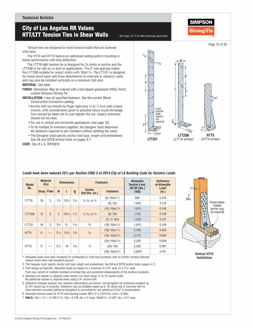
Tension ties are designed to resist tension loads that are fastened with nails.
The HTT4 and HTT5 feature an optimized nailing pattern resulting in better performance with less deflection.
The LTT19 light tension tie is designed for 2x joists or purlins and the LTT20B is for nail-on or bolt-on applications. The 3" nail spacing makes the LTT20B suitable for wood I-joists with 10dx1 1⁄2. The LTTI31 is designed for wood chord open web truss attachments to concrete or masonry walls and may also be installed vertically on a minimum 2x6 stud.MATERIAL: See tableFINISH: Galvanized. May be ordered with a hot-dipped galvanized (HDG) finish; contact Simpson Strong-Tie.INSTALLATION: • Use all specified fasteners. See the current Wood Construction Connectors catalog.
• Anchor bolt nut should be finger tight plus 1⁄3 to 1⁄2 turn with a hand wrench, with consideration given to possible future wood shrinkage. Care should be taken not to over-tighten the nut. Impact wrenches should not be used.
• For use in vertical and horizontal applications (see page 16).• To tie multiple 2x members together, the Designer must determine
the fasteners required to join members without splitting the wood.• The Designer shall specify anchor bolt type, length and embedment.
See SB and SSTB anchor bolts on pages 4-7.CODE: City of L.A. RR25818
Page 12 of 20
See Pages 15-17 for Wall Anchorage Assemblies
Loadtransferplatewashernotrequired
LTTI31LTT20B
(LTT19 similar)HTT5
(HTT4 similar)
ModelNo.
Material (Ga) Dimensions Fasteners Allowable
Tension Load, DF/SP (lbs.)
(160)
Deflection at Allowable
Load5 (in.)Strap Plate W L CL
AnchorBolt Dia. (in.) Fasteners
LTT19 16 3 1 3⁄4 19 1⁄8 1 3⁄8 1⁄2, 5⁄8, or 3⁄4(8) 10dx1 1⁄2 985 0.135
(8) 10d 1,005 0.118
LTT20B 12 3 2 19 3⁄4 1 1⁄2 1⁄2, 5⁄8, or 3⁄4
(10) 10dx1 1⁄2 1,015 0.146
(8) 10d 1,125 0.139
(2) 1⁄2" Bolt 1,220 0.137
LTTI31 18 3 3 3⁄4 31 1 3⁄8 5⁄8 (18) 10dx1 1⁄2 1,010 0.145
HTT4 11 — 2 1⁄2 12 3⁄8 1 3⁄8 5⁄8(18) 10dx1 1⁄2 2,705 0.065
(18) 16dx2 1⁄2 3,175 0.092
HTT5 11 — 2 1⁄2 16 1 3⁄8 5⁄8
(26) 10dx1 1⁄2 3,265 0.090
(26) 10d 3,505 0.087
(26) 16dx2 1⁄2 3,8206 0.101
1. Allowable loads have been increased for earthquake or wind load durations with no further increase allowed; reduce where other load durations govern.2. The Designer must specify anchor bolt type, length and embedment. See SB and SSTB Anchor bolts (pages 4-7).3. Post design by Specifier. Allowable loads are based on a minimum 3"x3 1⁄2" post (in a 3 1⁄2" wall). Post may consist of multiple members provided they are connected independently of the holdown fasteners.4. Standard cut washer is required under anchor nut when using 1⁄2" or 5⁄8" anchor bolts. No additional washer is required when using a 3⁄4" anchor bolt.5. Deflection includes fastener slip, holdown deformation and anchor rod elongation for holdowns installed up to 4 1⁄2" above top of concrete. Holdowns may be installed raised up to 18" above top of concrete with no load reduction provided additional elongation is accounted for (an additional 0.010" is conservative). 6. Allowable tension loads for HTT5 with bearing washer BP5⁄8-2 is 3,970 lbs. (Δall = 0.095).7. NAILS: 10d x 1 1⁄2" = 0.148"x1 1⁄2"; 10d = 0.148" dia. x 3" long; 16dx2 1⁄2" = 0.162" dia. x 2 1⁄2" long.
Loads have been reduced 25% per Section 2305.5 of 2014 City of LA Building Code for Seismic Loads.
Preservative-treated
barrier maybe required
3"Min.
Vertical HTT4 Installation
Technical Bulletin
© 2015 Simpson Strong-Tie Company Inc. T-C-HDLA15
City of Los Angeles RR Values Straps
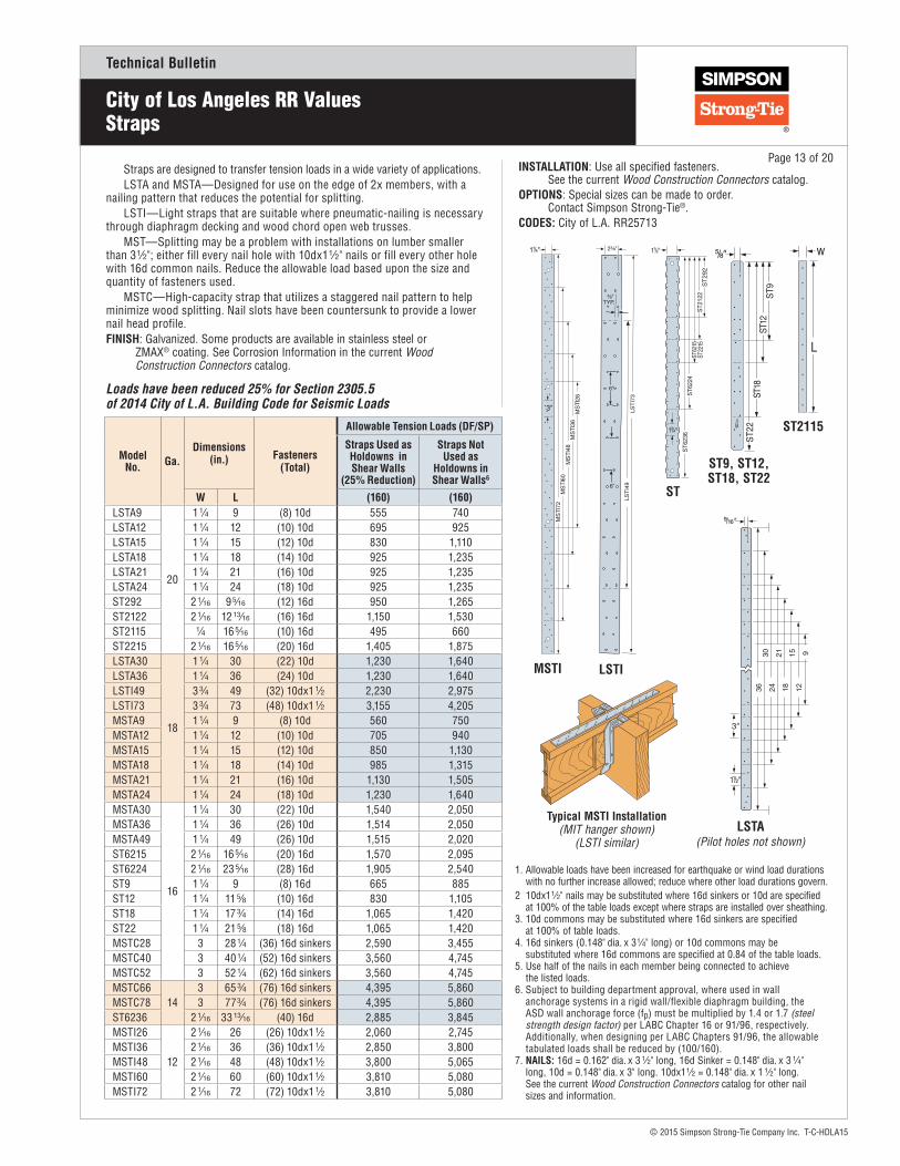
Straps are designed to transfer tension loads in a wide variety of applications. LSTA and MSTA—Designed for use on the edge of 2x members, with a
nailing pattern that reduces the potential for splitting.LSTI—Light straps that are suitable where pneumatic-nailing is necessary
through diaphragm decking and wood chord open web trusses.MST—Splitting may be a problem with installations on lumber smaller
than 3 1⁄2"; either fill every nail hole with 10dx1 1⁄2" nails or fill every other hole with 16d common nails. Reduce the allowable load based upon the size and quantity of fasteners used.
MSTC—High-capacity strap that utilizes a staggered nail pattern to help minimize wood splitting. Nail slots have been countersunk to provide a lower nail head profile.FINISH: Galvanized. Some products are available in stainless steel or ZMAX® coating. See Corrosion Information in the current Wood Construction Connectors catalog.
INSTALLATION: Use all specified fasteners. See the current Wood Construction Connectors catalog.OPTIONS: Special sizes can be made to order. Contact Simpson Strong-Tie®.CODES: City of L.A. RR25713
Typical MSTI Installation (MIT hanger shown)
(LSTI similar)
Model No. Ga.
Dimensions (in.) Fasteners
(Total)
Allowable Tension Loads (DF/SP)
Straps Used as Holdowns in Shear Walls
(25% Reduction)
Straps Not Used as
Holdowns in Shear Walls6
W L (160) (160)LSTA9
20
1 1⁄4 9 (8) 10d 555 740LSTA12 1 1⁄4 12 (10) 10d 695 925LSTA15 1 1⁄4 15 (12) 10d 830 1,110LSTA18 1 1⁄4 18 (14) 10d 925 1,235LSTA21 1 1⁄4 21 (16) 10d 925 1,235LSTA24 1 1⁄4 24 (18) 10d 925 1,235ST292 2 1⁄16 9 5⁄16 (12) 16d 950 1,265ST2122 2 1⁄16 12 13⁄16 (16) 16d 1,150 1,530ST2115 1⁄4 16 5⁄16 (10) 16d 495 660ST2215 2 1⁄16 16 5⁄16 (20) 16d 1,405 1,875LSTA30
18
1 1⁄4 30 (22) 10d 1,230 1,640LSTA36 1 1⁄4 36 (24) 10d 1,230 1,640LSTI49 3 3⁄4 49 (32) 10dx1 1⁄2 2,230 2,975LSTI73 3 3⁄4 73 (48) 10dx1 1⁄2 3,155 4,205MSTA9 1 1⁄4 9 (8) 10d 560 750MSTA12 1 1⁄4 12 (10) 10d 705 940MSTA15 1 1⁄4 15 (12) 10d 850 1,130MSTA18 1 1⁄4 18 (14) 10d 985 1,315MSTA21 1 1⁄4 21 (16) 10d 1,130 1,505MSTA24 1 1⁄4 24 (18) 10d 1,230 1,640MSTA30
16
1 1⁄4 30 (22) 10d 1,540 2,050MSTA36 1 1⁄4 36 (26) 10d 1,514 2,050MSTA49 1 1⁄4 49 (26) 10d 1,515 2,020ST6215 2 1⁄16 16 5⁄16 (20) 16d 1,570 2,095ST6224 2 1⁄16 23 5⁄16 (28) 16d 1,905 2,540ST9 1 1⁄4 9 (8) 16d 665 885ST12 1 1⁄4 11 5⁄8 (10) 16d 830 1,105ST18 1 1⁄4 17 3⁄4 (14) 16d 1,065 1,420ST22 1 1⁄4 21 5⁄8 (18) 16d 1,065 1,420MSTC28 3 28 1⁄4 (36) 16d sinkers 2,590 3,455MSTC40 3 40 1⁄4 (52) 16d sinkers 3,560 4,745MSTC52 3 52 1⁄4 (62) 16d sinkers 3,560 4,745MSTC66
143 65 3⁄4 (76) 16d sinkers 4,395 5,860
MSTC78 3 77 3⁄4 (76) 16d sinkers 4,395 5,860ST6236 2 1⁄16 33 13⁄16 (40) 16d 2,885 3,845MSTI26
12
2 1⁄16 26 (26) 10dx1 1⁄2 2,060 2,745MSTI36 2 1⁄16 36 (36) 10dx1 1⁄2 2,850 3,800MSTI48 2 1⁄16 48 (48) 10dx1 1⁄2 3,800 5,065MSTI60 2 1⁄16 60 (60) 10dx1 1⁄2 3,810 5,080MSTI72 2 1⁄16 72 (72) 10dx1 1⁄2 3,810 5,080
LSTA (Pilot holes not shown)
Loads have been reduced 25% for Section 2305.5 of 2014 City of L.A. Building Code for Seismic Loads
1. Allowable loads have been increased for earthquake or wind load durations with no further increase allowed; reduce where other load durations govern.2 10dx1 1⁄2" nails may be substituted where 16d sinkers or 10d are specified at 100% of the table loads except where straps are installed over sheathing.3. 10d commons may be substituted where 16d sinkers are specified at 100% of table loads.4. 16d sinkers (0.148" dia. x 3 1⁄4" long) or 10d commons may be substituted where 16d commons are specified at 0.84 of the table loads.5. Use half of the nails in each member being connected to achieve the listed loads. 6. Subject to building department approval, where used in wall anchorage systems in a rigid wall/flexible diaphragm building, the ASD wall anchorage force (fp) must be multiplied by 1.4 or 1.7 (steel strength design factor) per LABC Chapter 16 or 91/96, respectively. Additionally, when designing per LABC Chapters 91/96, the allowable tabulated loads shall be reduced by (100/160).7. NAILS: 16d = 0.162" dia. x 3 1⁄2" long, 16d Sinker = 0.148" dia. x 3 1⁄4" long, 10d = 0.148" dia. x 3" long. 10dx1 1⁄2 = 0.148" dia. x 1 1⁄2" long. See the current Wood Construction Connectors catalog for other nail sizes and information.
MSTI
6"
LSTI
ST
ST9, ST12, ST18, ST22
ST2115
Page 13 of 20
Technical Bulletin
© 2015 Simpson Strong-Tie Company Inc. T-C-HDLA15
City of Los Angeles RR Values Straps
Page 14 of 20
Model No.
Clear Span(in.)
Fasteners (Total)
Allowable Tension Loads DF/SP (lbs.)Straps Used
as Holdowns in Shear Walls
(25% Reduction)
Straps Not Used as Holdowns in
Shear Walls
(160) (160)4
MSTA4918 (26) 10d 1,515 2,02016 (26) 10d 1,515 2,020
MSTC2818 (12) 16d sinkers 865 1,15516 (16) 16d sinkers 1,155 1,540
MSTC4018 (28) 16d sinkers 2,020 2,69516 (36) 16d sinkers 2,600 3,465
MSTC5218 (44) 16d sinkers 3,175 4,23516 (48) 16d sinkers 3,465 4,620
MSTC6618 (64) 16d sinkers 4,395 5,86016 (68) 16d sinkers 4,395 5,860
MSTC7818 (76) 16d sinkers 4,395 5,86016 (76) 16d sinkers 4,395 5,860
MST3718 (20) 16d 1,850 2,46516 (22) 16d 2,035 2,710
MST4818 (32) 16d 2,770 3,69516 (34) 16d 2,770 3,695
MST6018 (46) 16d 3,625 4,83016 (48) 16d 3,625 4,830
MST7218 (46) 16d 3,625 4,83016 (48) 16d 3,625 4,830 MST
MSTA (Pilot holes not shown)
MSTC28
CS16 Hole Pattern(all other CS straps similar)
CMST14 Hole Pattern (CMST12 similar)
CMSTC16 Hole Pattern
Model No.
Total Length
(ft.)Ga.
DF/SP Allowable Tension Loads DF/SP (lbs.)
Fasteners (Total)
End Length
(in.)
Straps Used as Holdowns in Shear Walls
(25% Reduction)
Straps Not Used as
Holdowns in Shear Walls4
(160) (160)
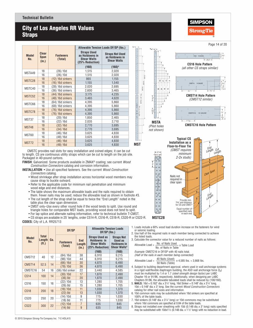
CMST12 40 12 (84) 16d 38 6,910 9,215(98) 10d 44 6,910 9,215
CMST14 52.5 14 (66) 16d 30 4,870 6,490(78) 10d 36 4,870 6,490
CMSTC16 54 16 (56) 16d sinker 22 3,440 4,585
CS14 100 14 (30) 10d 17 1,870 2,490(36) 8d 20 1,870 2,490
CS16 150 16 (22) 10d 13 1,280 1,705(26) 8d 15 1,280 1,705
CS18 200 18 (18) 10d 11 1,030 1,370(22) 8d 13 1,030 1,370
CS20 250 20 (14) 10d 9 775 1,030(18) 8d 11 775 1,030
CS22 300 22 (12) 10d 7 635 845(14) 8d 9 635 845
1. Loads include a 60% wood load duration increase on the fasteners for wind or seismic loading.2. Use half of the required nails in each member being connected to achieve the listed loads.3. Calculate the connector value for a reduced number of nails as follows:
4. Subject to building department approval, where used in wall anchorage systems in a rigid wall/flexible diaphragm building, the ASD wall anchorage force (fp) must be multiplied by 1.4 or 1.7 (steel strength design factor) per LABC Chapter 16 or 91/96, respectively. Additionally, when designing per LABC Chapters 91/96, the allowable tabulated loads shall be reduced by (100/160).5. NAILS: 16d = 0.162" dia. x 3 1⁄2" long, 16d Sinker = 0.148" dia. x 3 1⁄4" long, 10d = 0.148" dia. x 3" long. See the current Wood Construction Connectors catalog for other nail sizes and information.6. 10d common nails may be substituted where 16d sinkers are specified at 100% of the table loads.7. 16d sinkers (0.148" dia. x 3 1⁄4" long) or 10d commons may be substituted where 16d commons are specified at 0.84 of the table loads.8. Straps not installed over sheathing with 10d (0.148 dia. x 3" long) nails specified may be substituted with 10dx1 1⁄2 (0.148 dia. x 1 1⁄2" long) with no reduction in load.
No. of Nails UsedAllowable Load = x Table LoadNo. of Nails in Table
Example: CMSTC16 in DF/SP with 40 nails total. (Half of the nails in each member being connected)
40 Nails (Used) x 4,585 lbs. = 3,668 lbs.Allowable Load = 50 Nails (Table)
CMSTC provides nail slots for easy installation and coined edges; it can be cut to length. CS are continuous utility straps which can be cut to length on the job site. Packaged in 40-pound cartons. FINISH: Galvanized. Some products available in ZMAX® coating; see current Wood Construction Connectors catalog and corrosion information.INSTALLATION: • Use all specified fasteners. See the current Wood Construction Connectors catalog.
• Wood shrinkage after strap installation across horizontal wood members may cause strap to buckle outward.
• Refer to the applicable code for minimum nail penetration and minimum wood edge and end distances.
• The table shows the maximum allowable loads and the nails required to obtain them. Fewer nails may be used; reduce the allowable load as shown in footnote #3.
• The cut length of the strap shall be equal to twice the “End Length” noted in the table plus the clear span dimension.
• CMST only–Use every other round hole if the wood tends to split. Use round and triangle holes for comparable MST loads, providing wood does not tend to split.
• For lap splice and alternate nailing information, refer to technical bulletin T-CMST.• CS straps are available in 25' lengths, order CS14-R, CS16-R, CS18-R, CS20-R or CS22-R.
CODES: City of L.A. RR25713
Clear Span
End
Length
End Length Cut
Length
Nails not required in clear span
Typical CS Installation as a
Floor-to-Floor Tie (CMST requires
minimum 2-2x studs)
Technical Bulletin
© 2015 Simpson Strong-Tie Company Inc. T-C-HDLA15
Hanger not shown for clarity
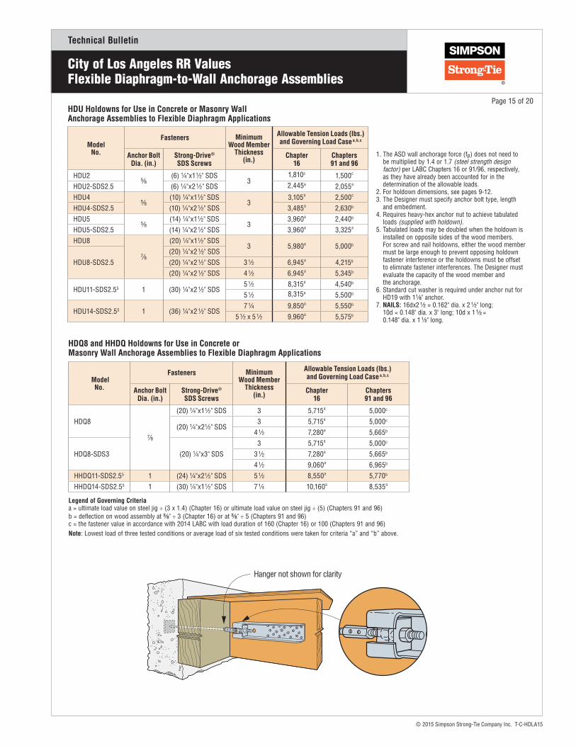
City of Los Angeles RR ValuesFlexible Diaphragm-to-Wall Anchorage Assemblies
Model No.
Fasteners Minimum Wood Member
Thickness (in.)
Allowable Tension Loads (lbs.) and Governing Load Case a, b, c
Anchor Bolt Dia. (in.)
Strong-Drive®
SDS ScrewsChapter
16Chapters 91 and 96
HDU25⁄8
(6) 1⁄4"x1 1⁄2" SDS3
1,810c 1,500c
HDU2-SDS2.5 (6) 1⁄4"x2 1⁄2" SDS 2,445a 2,055a
HDU45⁄8
(10) 1⁄4"x1 1⁄2" SDS3
3,105a 2,500c
HDU4-SDS2.5 (10) 1⁄4"x2 1⁄2" SDS 3,485a 2,630b
HDU55⁄8
(14) 1⁄4"x1 1⁄2" SDS3
3,960a 2,440b
HDU5-SDS2.5 (14) 1⁄4"x2 1⁄2" SDS 3,960a 3,325a
HDU8
7⁄8
(20) 1⁄4"x1 1⁄2" SDS3 5,980a 5,000b
HDU8-SDS2.5(20) 1⁄4"x2 1⁄2" SDS(20) 1⁄4"x2 1⁄2" SDS 3 1⁄2 6,945a 4,215b
(20) 1⁄4"x2 1⁄2" SDS 4 1⁄2 6,945a 5,345b
HDU11-SDS2.55 1 (30) 1⁄4"x2 1⁄2" SDS5 1⁄2 8,315a 4,540b
5 1⁄2 8,315a 5,500b
HDU14-SDS2.55 1 (36) 1⁄4"x2 1⁄2" SDS7 1⁄4 9,850a 5,550b
5 1⁄2 x 5 1⁄2 9,960a 5,575b
1. The ASD wall anchorage force (fp) does not need to be multiplied by 1.4 or 1.7 (steel strength design factor) per LABC Chapters 16 or 91/96, respectively, as they have already been accounted for in the determination of the allowable loads. 2. For holdown dimensions, see pages 9-12.3. The Designer must specify anchor bolt type, length and embedment. 4. Requires heavy-hex anchor nut to achieve tabulated loads (supplied with holdown).5. Tabulated loads may be doubled when the holdown is installed on opposite sides of the wood members. For screw and nail holdowns, either the wood member must be large enough to prevent opposing holdown fastener interference or the holdowns must be offset to elimnate fastener interferences. The Designer must evaluate the capacity of the wood member and the anchorage. 6. Standard cut washer is required under anchor nut for HD19 with 1 1⁄8" anchor. 7. NAILS: 16dx2 1⁄2 = 0.162" dia. x 2 1⁄2" long; 10d = 0.148" dia. x 3" long; 10d x 1 1⁄2 = 0.148" dia. x 1 1⁄2" long.
HDU Holdowns for Use in Concrete or Masonry Wall Anchorage Assemblies to Flexible Diaphragm Applications
Model No.
Fasteners Minimum Wood Member
Thickness (in.)
Allowable Tension Loads (lbs.) and Governing Load Case a, b, c
Anchor Bolt Dia. (in.)
Strong-Drive®
SDS ScrewsChapter
16Chapters 91 and 96
HDQ8
7⁄8
(20) 1⁄4"x1 1⁄2" SDS 3 5,715a 5,000c
(20) 1⁄4"x2 1⁄2" SDS3 5,715a 5,000c
4 1⁄2 7,280a 5,665b
HDQ8-SDS3 (20) 1⁄4"x3" SDS3 5,715a 5,000c
3 1⁄2 7,280a 5,665b
4 1⁄2 9,060a 6,965b
HHDQ11-SDS2.55 1 (24) 1⁄4"x2 1⁄2" SDS 5 1⁄2 8,550a 5,770b
HHDQ14-SDS2.55 1 (30) 1⁄4"x1 1⁄2" SDS 7 1⁄4 10,160a 8,535a
HDQ8 and HHDQ Holdowns for Use in Concrete or Masonry Wall Anchorage Assemblies to Flexible Diaphragm Applications
Legend of Governing Criteria a = ultimate load value on steel jig ÷ (3 x 1.4) (Chapter 16) or ultimate load value on steel jig ÷ (5) (Chapters 91 and 96)b = deflection on wood assembly at 3⁄8" ÷ 3 (Chapter 16) or at 3⁄8" ÷ 5 (Chapters 91 and 96) c = the fastener value in accordance with 2014 LABC with load duration of 160 (Chapter 16) or 100 (Chapters 91 and 96)Note: Lowest load of three tested conditions or average load of six tested conditions were taken for criteria “a” and “b” above.
Page 15 of 20

Technical Bulletin
© 2015 Simpson Strong-Tie Company Inc. T-C-HDLA15
City of Los Angeles RR ValuesFlexible Diaphragm-to-Wall Anchorage Assemblies
Model No.
Fasteners Minimum Wood
Member Thickness
(in.)
Allowable Tension Loads (lbs.) and Governing Load Case a, b, c
Anchor Bolt Dia.
(in.)
StudBolts
Chapter 16
Chapters 91 and 96
HD3B 5⁄8 (2) 5⁄8
1 1⁄2 1,420b 750b
2 1⁄2 1,955b 1,250b
3 2,815b 1,960c
HD5B 5⁄8 (2) 3⁄42 1⁄2 3,660b 2,135b
3 1⁄2 3,980b 2,245b
HD7B 7⁄8 (3) 3⁄4 3 5,620a 2,955b
HD9B 7⁄8 (3) 7⁄83 1⁄2 6,045b 3,680b
4 1⁄2 5,505b 2,225b
HD12 1 1⁄8 (4) 1
3 1⁄2 7,225b 3,555b
4 1⁄2 9,180b 5,545b
5 1⁄2 8,610b 4,130b
7 1⁄4 6,550b 3,175b
5 1⁄2 x 5 1⁄2 10,680a 5,135b
HD197
1 1⁄8 (5) 17 1⁄4 8,595b 4,315b
5 1⁄2 x 5 1⁄2 7,405b 3,785b
1 1⁄4 (5) 17 1⁄4 11,135b 4,865b
5 1⁄2 x 5 1⁄2 16,270a 9,925b
1. The ASD wall anchorage force (fp) does not need to be multiplied by 1.4 or 1.7 (steel strength design factor) per LABC Chapters 16 or 91/96, respectively, as they have already been accounted for in the determination of the allowable loads. 2. For holdown dimensions, see pages 9–12.3. The Designer must specify anchor bolt type, length and embedment. 4. Requires heavy hex anchor nut to achieve tabulated loads (supplied with holdown).5. Tabulated loads may be doubled when the holdown is installed on opposite sides of the wood members. For screw and nail holdowns, either the wood member must be large enough to prevent opposing holdown fastener interference or the holdowns must be offset to elimnate fastener interferences. The Designer must evaluate the capacity of the wood member and the anchorage. 6. Standard cut washer is required under anchor nut for HD19 with 1 1⁄8" anchor. 7. Nails: 16dx2 1⁄2 = 0.162" dia. x 2 1⁄2" long; 10d = 0.148" dia. x 3" long; 10d x 1 1⁄2 = 0.148" dia. x 1 1⁄2" long.
HD and HDB Holdowns for Use in Concrete or Masonry Wall Anchorage Assemblies to Flexible Diaphragm Applications
LTT and HTT Tension Ties for Use in Concrete or Masonry Wall Anchorage Assemblies to Flexible Diaphragm Applications
Model No.
Fasteners Minimum Wood
Member Thickness
(in.)
Allowable Tension Loads (lbs.) and Governing Load Case a, b, c
Anchor Bolt Dia.
(in.)Fasteners Chapter
16Chapters 91 and 96
LTT191⁄2, 5⁄8, or 3⁄4
(8) 10dx1 1⁄23
825b 455b
(8) 10d 865b 370b
LTT20B1⁄2, 5⁄8, or 3⁄4
(10) 10dx1 1⁄2
3
535b 385b
(10) 10d 630b 320b
(2) 1⁄2" Bolt 840b 490b
LTTI31 5⁄8 (18) 10dx1 1⁄2 3 490b 265b
HTT4 5⁄8(18) 10dx1 1⁄2
33,610a 2,665c
(18) 16dx2 1⁄2 3,650a 2,645b
HTT5 5⁄8
(26) 10dx1 1⁄2
3
3,685a 2,110b
(26) 10d 3,685a 3,095a
(26) 16dx2 1⁄2 3,685a 3,085b
HTT5KT 5⁄8 (26) SD #10x2 1⁄2 3
HTT5-3⁄4 3⁄4
(26) 10dx1 1⁄2
3(26) SD #10x1 1⁄2
(26) 16dx2 1⁄2
Page 16 of 20
Hanger Not ShownFor Clarity
Horizontal HTT Installation
2"
Horizontal LTT19 Installation (LTT20B similar)
Horizontal HDB Installation
Legend of Governing Criteria a = ultimate load value on steel jig ÷ (3 x 1.4) (Chapter 16) or ultimate load value on steel jig ÷ (5) (Chapters 91 and 96)b = deflection on wood assembly at 3⁄8" ÷ 3 (Chapter 16) or at 3⁄8" ÷ 5 (Chapters 91 and 96) c = the fastener value in accordance with 2014 LABC with load duration of 160 (Chapter 16) or 100 (Chapters 91 and 96)Note: Lowest load of three tested conditions or average load of six tested conditions were taken for criteria “a” and “b” above.

Technical Bulletin
© 2015 Simpson Strong-Tie Company Inc. T-C-HDLA15
City of Los Angeles RR Values PCT Purlin Cross Tie (Used in Flexible Diaphragm-to-Wall Anchorage Assemblies)
FEATURES: • Designed using a section that works in both tension and compression. • Tube section helps with drilling alignment, through the purlin. • Offset angle to allow drilling access through glulam.MATERIAL: 1 1⁄2" square tube steel ASTM A500 Grade BFINISH: Galvanized.INSTALLATION: • Use all specified fasteners. Refer to the current Simpson Strong-Tie® Wood Construction Connector catalog for General Notes and warranty information. • PCT18 and 23 are sized to span a maximum hanger seat depth (“B” dimension) of 4". PCT27 and 38 are sized to span a maximum hanger seat depth (“B” dimension) of 6". • 2 1⁄2" or a 2 9⁄16" diameter hole required. • Install in pairs.OPTIONS: Contact Simpson Strong-Tie for other lengths.CODES: City of L.A. RR25719.
ModelNo.
Dimensions (in.) Total Length
(in.)
Fasteners Dia.
Allowable Load per Pair of PCT (lbs.)
Steel Tension6
Steel Compression6
Bolts (Double Shear) Length of Bolt in Purlin – DF/SP
L L1 L2 3 1⁄8" 3 1⁄2" 5 1⁄8" 5 1⁄2" 6 3⁄4"
Wall Anchorage Design per LABC Chapter 16 (CD = 1.6)
PCT18 44 3⁄4 14 17 3⁄4 44 3⁄4 (8) 5⁄8" MB 17,620a 13,690a 17,235c 18,170b 18,170b 18,170b 18,170b
PCT23 52 3⁄4 14 17 3⁄4 52 3⁄4 (10) 5⁄8" MB 17,620a 13,690a 18,170b 18,170b 18,170b 18,170b 18,170b
PCT27 66 3⁄4 19 1⁄2 23 1⁄2 66 5⁄8 (12) 5⁄8" MB 28,335a 20,475a 24,855c 27,705c 28,400c 28,430c 28,255c
PCT38 71 5⁄8 19 1⁄2 23 1⁄2 71 5⁄8 (12) 3⁄4" MB 25,260a 18,595a 25,540b 25,540b 25,540b 25,540b 25,540b
Wall Anchorage Design per LABC Chapters 91 and 96 (CD = 1.0)
PCT18 44 3⁄4 14 17 3⁄4 44 3⁄4 (8) 5⁄8" MB 14,800a 11,500a 10,770c 10,900b 10,900b 10,900b 10,900b
PCT23 52 3⁄4 14 17 3⁄4 52 3⁄4 (10) 5⁄8" MB 14,800a 11,500a 10,900b 10,900b 10,900b 10,900b 10,900b
PCT27 66 3⁄4 19 1⁄2 23 1⁄2 66 5⁄8 (12) 5⁄8" MB 23,800a 17,200a 15,535c 17,315c 17,730b 17,730b 17,660c
PCT38 71 5⁄8 19 1⁄2 23 1⁄2 71 5⁄8 (12) 3⁄4" MB 15,620a 15,618a 15,320b 15,320b 15,320b 15,320b 15,320b
1. Loads shall not be increased for short-term wood load duration factor nor the one-third steel stress increase.2. Install PCT purlin crossties in pairs.3. Minimum bolt length is: Purlin width + 3" (PCT) + 1" (nut).4. Allowable loads for bolts assume a purlin with a minimum depth of 10 1⁄2".5. Designer is responsible for evaluating all wood members.6. The ASD wall anchorage force (fp) does not need to be multiplied by 1.4 or 1.7 (steel strength design factor) per LABC Chapters 16 or 91/96, respectively, as they have already been accounted for in the determination of the allowable loads.7. Designer to take lower of steel or bolt value.
PCT Purlin Cross Ties for Use in Concrete Masonry Wall Anchorage Assemblies to Flexible Diaphragm Applications
PCT Installed in Pairs(Top View)
Typical PCT Installation
PCT U.S. Patent 6,862,854
Page 17 of 20
Legend of Governing Criteria a = ultimate load value on steel jig ÷ (3 x 1.4) (Chapter 16) or ultimate load value on steel jig ÷ (5) (Chapters 91 and 96)b = deflection on wood assembly at 3⁄8" ÷ 3 (Chapter 16) or at 3⁄8" ÷ 5 (Chapters 91 and 96) c = the fastener value in accordance with 2014 LABC with load duration of 160 (Chapter 16) or 100 (Chapters 91 and 96)
Technical Bulletin
© 2015 Simpson Strong-Tie Company Inc. T-C-HDLA15
City of Los Angeles RR ValuesDesign Example for Wall Anchorage
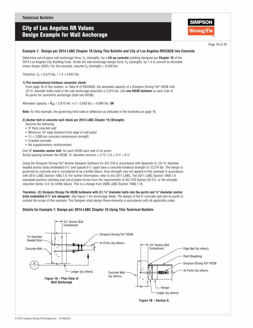
Determine out-of-plane wall anchorage force, Fp (strength), for a tilt-up concrete building designed per Chapter 16 of the 2014 Los Angeles City Building Code. Divide the wall anchorage design force, Fp (strength), by 1.4 to convert to allowable stress design (ASD). For this example, assume Fp (strength) = 6,500 lbs.:
Therefore, Fp = 6,575 lbs. / 1.4 = 4,642 lbs.
1) Pre-manufactured holdown connector check: From page 16 of this bulletin, or Table B of RR25828, the allowable capacity of a Simpson Strong-Tie® HD3B with (2) 5⁄8" diameter bolts used in the wall anchorage assembly is 2,815 lbs. Use one HD3B holdown on each side of 4x purlin for concentric anchorage (total two HD3B).
Allowable capacity = Pall = 2,815 lbs. x 2 = 5,630 lbs. > 4,696 lbs. OK
Note: for this example, the governing limit state is deflection as indicated in the footnotes on page 16.
2) Anchor bolt in concrete wall check per 2014 LABC Chapter 19 (Strength): Assume the following: • 9" thick concrete wall • Minimum 10" edge distance from edge of wall panel • f’c = 3,000 psi concrete compressive strength • Cracked concrete • No supplementary reinforcement
One 5⁄8" diameter anchor bolt. for each HD3B each side of 4x purlinActual spacing between the HD3B, 5⁄8" diameter anchors = (1 3⁄8" x 2) + 3 1⁄2" = 6 1⁄4"
Using the Simpson Strong-Tie® Anchor Designer Software for ACI 318 in accordance with Appendix D, (2) 5⁄8" diameter headed anchor bolts embedded 5 1⁄2" and spaced 6 1⁄4" apart have a concrete breakout strength of 12,274 lbs. The design is governed by concrete and is considered to be a brittle failure. Over-strength was not applied in this example in accordance with 2014 LABC Section 1905.1.9. For further information, refer to the 2011 LABC. The 2011 LABC Section 1908.1.9 exempted anchors resisting wall out-of-plane forces from the requirements of ACI 318 Section D3.3.5, or the strength reduction factor, 0.4, for brittle failure. This is a change from 2008 LABC Section 1908.1.16.
Therefore, (2) Simpson Strong-Tie HD3B holdowns with (2 ) 5⁄8" diameter bolts into the purlin and 5⁄8" diameter anchor bolts embedded 5 ½" are adequate. See Figure 1 for Anchorage Detail. The design of the 9" concrete wall and 4x purlin is outside the scope of this example. The Designer shall design these elements in accordance with all applicable codes.
Example 1: Design per 2014 LABC Chapter 16 Using This Bulletin and City of Los Angeles RR25828 into Concrete
Details for Example 1: Design per 2014 LABC Chapter 16 Using This Technical Bulletin
Page 18 of 20
Figure 1A – Plan View of Wall Anchorage
Ledger (by others)
Concrete Wall
5½" Anchor Bolt Embedment
⅝" DiameterHeaded Stud
A
4x Purlin (by others)
Simpson Strong-Tie® HD3B
Figure 1B – Section A
Ledger (by others)
Concrete Wall(by others)
5½" Anchor BoltEmbedment
Hanger
4x Purlin (by others)
Simpson Strong-Tie® HD3B
Roof Sheathing
Edge Nail (by others)

Technical Bulletin
© 2015 Simpson Strong-Tie Company Inc. T-C-HDLA15
Determine out of plane wall anchorage force, Fp (strength), for a CMU building designed per Chapter 16 of the 2014 Los Angeles City Building Code. Divide the wall anchorage design force, Fp (strength), by 1.4 to convert to allowable stress design (ASD). For this example, assume Fp (strength) = 4,000 lbs.
Design force: Fp = 4,000 lbs. / 1.4 = 2,857 lbs. (ASD)
1) Pre-manufactured anchor connector check:From page 15 of the bulletin or Table I of Research Report RR 25720, the allowable capacity of Simpson Strong-Tie® HDU2 with 1⁄4"x1 1⁄2" Strong-Drive® SDS Heavy-Duty Connector screws used in the wall anchorage assembly is 1,810 lbs.
Use one HDU2 on each side of 4x purlin for concentric anchorage (total two HDU2).Allowable capacity = Pall = 1,810 lbs. x 2 = 3,620 lbs > 2,857 lbs. OK
2A) Anchor bolt in 8" CMU wall check per 2014 LABC 2107.1 (ASD):
f'm = 1,500 psi, No special inspection, Length of headed stud bolt embedment = lb = 3 1⁄2". One 5⁄8" diameter anchor bolts for each HDU2 on each side of 4x purlin.
Allowable load in tension, Ba, shall be the lesser of the following per ACI 530-11 Section 2.1.4.3.1.1:
Bab = 1.25Apt√(ƒ'm) Bas = 0.6Abfy Where: Apt = πlb2 with any adjustments per Section 1.17.2
Actual spacing between the HDU2, 5⁄8" diameter anchors = (1 3⁄8" x 2) + 3 1⁄2" = 6 1⁄4", which is 6.25/3.5 = 1.79 times the embedment depth or 1.79 lb.
Reduction due to anchor tension cone overlap (Ref. Reinf. Masonry Engin. Hdbk. Table ASD-7c) = R; Therefore, from RMEH Table ASD-7c, R = 0.97.
Apt = πlb2 = π (3.5)2 = 38.5 in2 Bab = 1.25Apt√(ƒ'm) (R)(1.33) = 1.25 (38.5) √1500 (0.97) (1.33) = 2,405 lbs. (ASD) governs Bas = 0.6Abfy = 0.6 (0.307) (36,000) (1.33) = 8,819 lbs. (ASD)
Pt = 2,405 lbs. x (2 anchor bolts) = 4,810 lbs. > 2,857 lbs. (ASD) OK
OR
2B) Anchor bolt in 8" CMU wall check per 2014 LABC 2108.1 (Strength Design):
f'm = 1,500 psi, Special inspection required, Length of embedment = lb = 3 1⁄2".
One 5⁄8" diameter A.B. for each HDU2 on each side of 4x purlin.
Actual spacing between the HDU2, 5⁄8" diameter anchors = (1 3⁄8" x 2) + 3 1⁄2" = 6 1⁄4", which is 6.25/3.5 = 1.79 times the embedment depth or 1.79 lb.
Reduction due to anchor tension cone overlap (Reference Reinforced Masonry Engineering Handbook Table ASD-7c) = R; Therefore, from RMEH Table ASD-7c, R = 0.97
Per ACI 530-11, Section 3.1.3, the design tensile strength = φBan.
Per Section 3.1.6.3.1.1, Ban is taken as the lower of: Ban = 4 Apt √(ƒ'm) (R) Bans = Ab fy
Apt = πlb2 = π (3.5)2 = 38.5 in2 Banb = 4 Apt √(ƒ'm) (R) = 4 (38.5) √1500 (0.97) = 5,785 lbs. governs Bans = Ab fy = (0.307) (36,000) = 11,052 lbs.
In accordance with Section 3.1.4.1, φ shall be taken as 0.50 when anchor design is controlled by masonry breakout. Thus, φBan = 0.50 (5,785 lbs.) (2 anchor bolts) = 5,785 lbs. > 4,000 lbs. (Strength) OK
Therefore, (2) Simpson Strong-Tie HDU2 holdowns with 1⁄4"x1 1⁄2" Strong-Drive® SDS Heavy-Duty Connector screws and 5⁄8" diameter anchor bolts embedded 4 1⁄2" are adequate. The design of the CMU block wall and 4x purlin is outside the scope of this example. The Designer shall design these elements in accordance with all applicable codes.
Example 2: Design per 2014 LABC Chapter 16 using this bulletin and City of Los Angeles RR25720 in CMU
City of Los Angeles RR ValuesDesign Example for Wall Anchorage
Page 19 of 20
4x Purlin (by others)
Ledger (by others)
CMUBlock Wall
4½" Anchor BoltEmbedment
Simpson Strong-Tie® HDU2 with Strong-Drive® ¼"x1½" SDS screws each side
⅝" DiameterHeaded Stud
A
Figure 1A – Plan View of Wall Anchorage
Ledger (by others)
CMUBlock Wall(by others)
Hanger
4½" Anchor Bolt Embedment
4x Purlin (by others)
Simpson Strong-Tie® HDU2 with Strong-Drive® ¼"x½" SDS screws each side
Roof Sheathing
Edge Nail (by others)
Figure 1B – Section A

800-999-5099www.strongtie.com
This flier is effective until December 31, 2017, and reflects information available as of December 1, 2015. This information is updated periodically and should not be relied upon after December 31, 2017; contact Simpson Strong-Tie for current information and limited warranty or see www.strongtie.com.
© 2015 Simpson Strong-Tie Company Inc. • P.O. Box 10789, Pleasanton, CA 94588 T-C-HDLA15 12/15 exp. 12/17
Technical Bulletin
City of Los Angeles RR ValuesDesign Example for Wall Anchorage
Determine the out-of-plane allowable stress design level wall anchorage design force (F) for a tilt-up concrete building designed per Chapter 91 or 96 of the 2014 Los Angeles City Building Code. For this example, assume F(ASD) = 3,150 lbs.
Design force: F(ASD) = 3,150 lbs.
1) Pre-manufactured anchor connector allowable capacity for design per 2014 LABC Chapter 91 or 96:
From page 16 of this bulletin or Table B of Research Report RR 25828, the allowable capacity of Simpson Strong-Tie® HD5B bolt holdowns used in the wall anchorage assembly is 2,135 lbs. Use one HD5B holdown on each side of 3x purlin for concentric anchorage.
Allowable capacity = Pall = 2,135 lbs. x 2 = 4,270 lbs. > 3,150 lbs. OK
2) Anchor bolt in concrete wall check per 2014 LABC Chapter 19 (Strength):
One 5⁄8" diameter F1554, Grade 36 all-thread rod embedded into Simpson Strong-Tie® SET-XP® high-strength anchoring adhesive for each HD5B each side of 3x purlin. Assume the following:
• 9 " thick concrete wall • Minimum 14" edge distance from top of wall • 2,500 psi concrete compressive strength • Cracked concrete • No supplementary reinforcement • Calculated strength force = ASD x 2.0 per Section 9108.2. 3,150 lbs. x 2 = 6,300 lbs.
Actual spacing between HD5B, 5⁄8" diameter anchors = (1 1⁄4" x 2) + 3 1⁄2" = 6"
The design is governed by concrete and is considered to be a brittle failure. Over-strength was not applied in this example in accordance with 2014 LABC Section 1905.1.9. For further information, refer to the 2011 LABC. The 2011 LABC Section 1908.1.9 exempted anchors resisting wall out-of-plane forces from the requirements of ACI 318 Section D3.3.5, or the strength reduction factor, 0.4, for brittle failure. This is a change from 2008 LABC Section 1908.1.16
Therefore, use (2) Simpson Strong-Tie HD5B holdowns with 5⁄8" dia. ASTM F1554 GR36 all-thread rods embedded 5 1⁄2" with Simpson Strong-Tie SET-XP. The evaluation of the existing purlin and concrete wall is outside the scope of this example. The Designer shall evaluate these elements in accordance with all applicable codes.
Example 3: Design per 2014 LABC Chapter 91 or 96 using this bulletin and City of Los Angeles RR25828 into Concrete
Page 20 of 20
Ledger (by others)
Concrete Wall
⅝" DiameterThreaded Stud
A
4x Purlin (by others)
Simpson Strong-Tie® HD5B
5½" Anchor Bolt Embedment
Figure 1A – Plan View of Wall Anchorage
4x Purlin (by others)
Ledger (by others)
Concrete Wall(by others)
5½" Threaded RodEmbedment
Hanger
Simpson Strong-Tie® HD5B
Roof Sheathing
Edge Nails (by others)
Figure 1B – Section A