technical catalogue radiant floor heating system - inicio · technical catalogue radiant floor...
TRANSCRIPT

TECHNICAL CATALOGUETECHNICAL CATALOGUE
RADIANT FLOORRADIANT FLOOR
HEATING SYSTEMHEATING SYSTEM
RADIANT FLOOR
HEATING SYSTEM
1
INDICE
Introduction ........................................................................................ 2
FloorStandard, the radiant floor heating system from Standard Hidraulica ...... 2
Reasons for working with FloorStandard ................................................... 2
Radiant Floor Concept ............................................................................ 3
Applications and Advantages ................................................................... 4
FloorStandard system description ............................................................ 5
Standard Hidraulica tubes for the FloorStandard system ........................... 6
Floor structure ..................................................................................... 8
Regulation system ............................................................................... 10
Design and installation recommendations ............................................... 13
Installing the radiant floor ...................................................................... 15
FloorStandard, the global offer ............................................................... 20

RADIANT FLOOR
HEATING SYSTEM
Presentation
FloorStandard® is Standard Hidrualica´s integral solution for achieving anenvironment of maximum comfort and energy-saving. Radiant floor climate controlprovides an even distribution of the heat thus obtaining maximum comfort. Bypushing water at low temperatures, heat losses are reduced between the generatorand the heat emitter.In case of sanitary and heating installations, technology has advanced amazinglyover the last few years with never before seen solutions which provide importantimprovements in terms of hygiene, hydraulics, economy, durability and installationmaintenance. Reason why the project designer must rely on trustworthymanufacturers with an acknowledged reputation due to their product's design,production and logistics. Standard Hidraulica, leading manufacturer for water, gas and heating valves, withthe essential aim of satisfying the client's needs, has broadened its range of products for heating installations. With thispurpose, the radiant floor heating System FloorStandard® has been incorporated.
FloorStandard®, Standard Hidraulica´s radiant heating system for floors
FloorStandard® is a radiant floor heating system that works at a low temperature(less than 29º at the surface) guaranteeing a unmatchable well-being and comfort.It consists of a radiation heating method that uses water as heat carrier fluid whichcirculates through a coil of polybuthylene tubes built-in a concrete plate whichconstitutes the temperature emitting element. Standard Hidraulica, with itsFloorStandard® range, offers complete and adapted solutions to this type ofheating system installation.
The system includes a complete range of provisions for each different component;insulating panels, perimeter isolation, polybuthylene tubes (PB) and multilayer(PE/AL/PE-X), collectors, regulation kit, additives for the optimum conduction ofheat, cupboard, thermostats.
• Knowledge of the technologyStandard Hidráulica provides the project designer complete solutions for the interior installations of the building withthe FloorStandard® system. The connectivity of the elements and the regulation of fluids are the technologies thatStandard Hidráulica has developed applying the most innovative concepts.
• Comfort, profitability and speedThe FloorStandard® system satisfies all the agents that intervene in the project's life cycle, including the building'sdesign, contracting, execution and operation. The project's designer, promoter and installation engineer may work inperfect co-ordination with the systems and products that Standard Hidráulica provides them.
• Safety and QualityStandard Hidráulica, has in its manufacturing plant, the ISO 9001 certification and its products as standardised bythe most important certifying agencies in Europe, for the traditional materials as well as the new products.
Reasons for working with FloorStandard®
2

TECHNICAL CATALOGUE
Radiant Floor Concept
In the radiant floor heating system with water at low temperatures, all the
pavement emits heat. Different to radiator systems that only exist at certain
focus points, the transmission of heat is carried out from the floor up, thus the
feet are the first to be warmed, later the rest of the body.
The effect over people is a sensation of comfort superior to the other heating
systems. Furthermore, this sensation is kept even when the air temperature is
only at 18 ºC. Consequently, the element that generates heat does not need to
function at high temperatures as is with a traditional heating system, achieving
more durability in the energy producing equipment and energy saving that can
reach 15% compared to a a traditional system.
From an architectural point of view, since the system is installed under the floor, it provides more flexibility in the
design and placement of the furniture and decoration elements, at the same time improving the aesthetics of the
interior space. Temperature control in each one of the rooms is carried out separately by means of regulating the
flow of hot water and separate circuits that are monitored with thermostats and valves.
Also included in this concept is the possibility of using the system for cooling spaced under determined conditions.
An additional effect of placing the system under the floor is totally avoiding the noise that other systems produce.
The radiant floor systems function with any heat producing element such as boilers, heat pumps, electric
accumulators and solar collecting plates. Furthermore, they are designed to be easily placed, with a reduced amount
of components, long lasting and a minimum level of maintenance. It is also important to mention that the use of
radiant floors is compatible with other systems within a home or building.
The radiant floor system is widely extended in European Countries. However, given the characteristics of its
installation, the designer must take into consideration a series of conditions, and among them is the material that
is to be used as flooring and the available height in the construction of the new home or in its restoration.
ºC ºC16 20 24
1,7 m
3
1,7 m
2,5 m 2,5 m
16 20 2416 20 24
Idealheating
Heating floorradiant floor
Shows the proximity ofFloorStandard ® to thetype of ideal solution for
heat distribution.
Heat in the floor and thelower temperatures in thehigher parts. A better well-
beign sensation.
Temperature is low in theflooe and higher in higherparts of the room. Not anideal situation.
Heating withradiators
Applications and Advantages
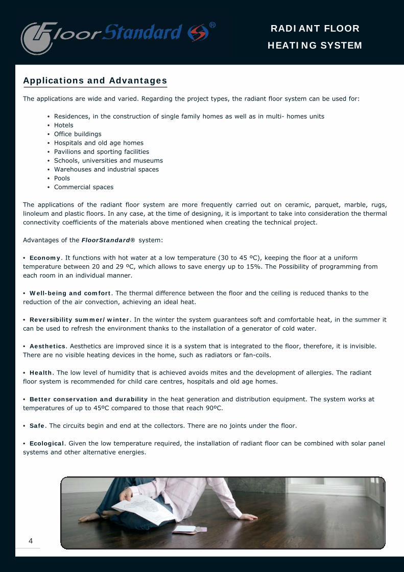
The applications are wide and varied. Regarding the project types, the radiant floor system can be used for:
• Residences, in the construction of single family homes as well as in multi- homes units• Hotels• Office buildings• Hospitals and old age homes • Pavilions and sporting facilities• Schools, universities and museums• Warehouses and industrial spaces• Pools• Commercial spaces
The applications of the radiant floor system are more frequently carried out on ceramic, parquet, marble, rugs,linoleum and plastic floors. In any case, at the time of designing, it is important to take into consideration the thermalconnectivity coefficients of the materials above mentioned when creating the technical project.
Advantages of the FloorStandard® system:
• Economy. It functions with hot water at a low temperature (30 to 45 ºC), keeping the floor at a uniformtemperature between 20 and 29 ºC, which allows to save energy up to 15%. The Possibility of programming fromeach room in an individual manner.
• Well-being and comfort. The thermal difference between the floor and the ceiling is reduced thanks to thereduction of the air convection, achieving an ideal heat.
• Reversibility summer/winter. In the winter the system guarantees soft and comfortable heat, in the summer itcan be used to refresh the environment thanks to the installation of a generator of cold water.
• Aesthetics. Aesthetics are improved since it is a system that is integrated to the floor, therefore, it is invisible.There are no visible heating devices in the home, such as radiators or fan-coils.
• Health. The low level of humidity that is achieved avoids mites and the development of allergies. The radiantfloor system is recommended for child care centres, hospitals and old age homes.
• Better conservation and durability in the heat generation and distribution equipment. The system works attemperatures of up to 45ºC compared to those that reach 90ºC.
• Safe. The circuits begin and end at the collectors. There are no joints under the floor.
• Ecological. Given the low temperature required, the installation of radiant floor can be combined with solar panelsystems and other alternative energies.
RADIANT FLOOR
HEATING SYSTEM
4

Description of the FloorStandard System
Standard Hidráulica has developed the FloorStandard® radiant
floor heating system complying with all the current demands of the
promoters, project designers and construction companies for a
modern, quick and economical installation.
Standard Hidráulica provides the market a complete system that
integrally solves the transport, distribution and regulation
installation of heat in any kind of building. Standard Hidráulica has
created and designed FloorStandard® has a complete system,
including with it all the necessary components and accessories for
each installation. Our company, furthermore, provides advice for
project designers so they can achieve better solutions in each
application.
In the case of heating by means of radiators, their surface may
reach a temperature of up tp 70ºC, since they are not in direct contact with people. In the case of the radiant floor,
they are in direct contact with people, thus, the temperature of the floor can not exceed certain values, which are:
- In offices 27ºC
- Waiting areas and living quarters 29ºC
- Bathrooms 33ºC
In the perimeter of the rooms, where feet do not normally enter into contact with the floor, a higher temperature is
allowed, up to 35ºC.
In comparison with other heating systems, the radiant floor us more linked to structural elements of the construction,
since the tubes are over the support and at the same time are covered with mortar. This means that the project
designer has to take into consideration the available height. For this reason, the quality demands of this type of
systems are very elevated and it is absolutely necessary to have a manufacturer such as Standard Hidráulica, in the
project as well as in the construction, which guarantees the following aspects:
• The quality of the tubes and their durability.• Guarantee of the system for 10 years• The reliability of the regulation system• The quality of design and calculation of the installation project
The distance between the tubes may vary according to the thermic charge. With values from 84 mm to a maximum
of 226 mm. The calculations for the use of heating only are not valid for the application of heating and refrigeration.
In all the cases where the radiant floor is also to be used in refrigeration, the calculation of the distance of the tubes
must be based in this last application, being conditions where the specific emission of the floor is limited. To obtain
a summer emission of 35-40 W/m², the corresponding winter emission must be between 90-100 W/m².
TECHNICAL CATALOGUE
5

Polyplumb tubes
The polyplumb tubes are made of polybuthylene (crystallised isotactic thermoplastic
polymer) and manufactured according to BS 7291 part 1 regulation, it is flexible and
strong, appropriate for cold and hot sanitary water, and for central heating systems. The
EVAL barrier prevents the passage of oxygen through the wall of the tubes, protecting the
metallic parts of the installation, according to the recommendations of the regulation
UNE-EN 1264-4. To protect the barrier during the installation of the tubes it has an
exterior polybuthylene layer. The barrier layer has a fine cover of adhesive on each side.
The polybuthylene tubes provide various advantages to installation engineers:
• Easiness in operation• Flexibility. Its extreme flexibility allows to operate it in any condition. • A vital safety factor of the highest designs.• Resistant to accidental impacts thanks to the material's elasticity. • Since it is not rigid and fragile, it is resistant to breakage due to freezing of the water.• Recyclable. The PB is a completely recyclable material, therefore it has a low environmental impact.
Characteristics Polyplumb MultiStandard
Resistence to corrosion Unaffected Unaffected
Permeability to Oxygen No No
Noise Transmission No No
Placement It can be curved without tools It can be curved with or without tools
manipulation / Malleable It does not retain form It does not retain form
Resistent to mechanical
agressions Scarcely Average
Placement on plate with
metal holder No Yes
Connection Techniques Compression Pressure or Compression
RADIANT FLOOR
HEATING SYSTEM
6
Standard Hidráulica tubes for the FloorStandard System
The pipe that is used for the distribution of water for heating requires special attention on behalf of the project designerto its properties and mechanical, technical and behaviour characteristics at a long term since this element will be partof the building's structure. Standard Hidráulica has two types of tubes for the radiant floor:
• Polyplumb: a Polybuthylene pipe with an oxygen barrier. The tubes have an alcohol layer of vinyl ethylene (EVAL)that prevents the passage of oxygen through the wall of the tubes.
• MultiStandard®: a multilayer pipe PE/AL/PE-X, reticulated polythene resistant to temperature with an aluminiumlayer that makes it impermeable to oxygen.
Polyplumb tubes and MultiStandard tubes for applications in radiant floors.

MultiStandard® Pipe
It is a multilayer, which structure is formed by three superimposed layers: one internal
reticulated polythene layer (PE-X), an intermediate aluminium layer welded with lasers
(minimum width 0.25 mm) and an external polythene (PE) layer. The intermediate layer
is linked to the exterior and interior layers with an adhesive layer that covers the
totality of the surface of the layers to guarantee total adhesion.
The multilayer pipe provides various advantages since it has the features of metallic
and synthesis tubes:
* It has less expansion
* It is impermeable to oxygen due to its aluminium layer
* It is unaffected by corrosion in the interior (PE-X) and the exterior (PE)
* It is flexible (it can easily be manipulated by hand)
* It is adaptable (it keeps it form)
(diagrama): PE / Adhesive / Aluminium / Adhesive / PE-X
The MultiStandard® pipe is manufactured for radiant floor installations in two
diameters which values are 16 x 2 and 20 x 2, certified by AENOR according to UNE
53961 EX.
The MultiStandard® pipe's properties and values are the following:
TECHNICAL CATALOGUE
7
Value Unit
16 x 2 20 x 2
0,026 mm/m.K
0,45 W/m.K
70 ºC
0,007 mm
16 20 mm
12 16 mm
2 2 mm
110 150 gr/m
Technical Properties
Linear expansion coefficient
Thermal conductivity coefficient
Maximum service temperature
Roughness coefficient
Exterior diameter
Interior diameter
Nominal width
Weight
Minimum curvature radius
without tools - 5 x D ext. 80
Minimum curvature radius
with tools
80 100 mm
45 60 mm
The Polyplumb pipe is manufactured and provided in two diameters; 15 x 1.7 and 18 x 2.2
Density
Thermal connectivity
Fusion point
Fragility Temperature
Expansion Coefficient
Elasticity Module
0.93 gramos/cm3
22 W / m ºC
125 ºC
-15 ºC
1,3 mm - 10 ºC
400 - 450 N / mm2
PE
AL
PE-X
Adhesivo
Adhesivo
RADIANT FLOOR
HEATING SYSTEM
8
Floor Structure
The floor, besides the tubes, is made, from the construction point of view, of isolation panels that are laterally
supported over a perimeter band to allow expansion movements, and horizontally supported over a polythene film
that avoids the transmission of humidity. Over the panels a mortar layer is poured which serves for spreading the heat
and over which the material that will be used as floor will be placed.
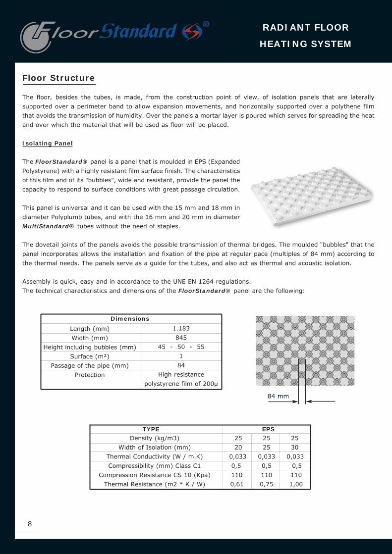
Isolating Panel
The FloorStandard® panel is a panel that is moulded in EPS (Expanded
Polystyrene) with a highly resistant film surface finish. The characteristics
of this film and of its "bubbles", wide and resistant, provide the panel the
capacity to respond to surface conditions with great passage circulation.
This panel is universal and it can be used with the 15 mm and 18 mm in
diameter Polyplumb tubes, and with the 16 mm and 20 mm in diameter
MultiStandard® tubes without the need of staples.
The dovetail joints of the panels avoids the possible transmission of thermal bridges. The moulded "bubbles" that the
panel incorporates allows the installation and fixation of the pipe at regular pace (multiples of 84 mm) according to
the thermal needs. The panels serve as a guide for the tubes, and also act as thermal and acoustic isolation.
Assembly is quick, easy and in accordance to the UNE EN 1264 regulations.
The technical characteristics and dimensions of the FloorStandard® panel are the following:
1.183
845
45 - 50 - 55
1
84
High resistance
polystyrene film of 200μ
Dimensions
TYPE EPS
Length (mm)
Width (mm)
Height including bubbles (mm)
Surface (m²)
Passage of the pipe (mm)
Protection
Density (kg/m3)
Width of Isolation (mm)
Thermal Conductivity (W / m.K)
Compressibility (mm) Class C1
Compression Resistance CS 10 (Kpa)
Thermal Resistance (m2 * K / W)
25 25 25
20 25 30
0,033 0,033 0,033
0,5 0,5 0,5
110 110 110
0,61 0,75 1,00
84 mm

TECHNICAL CATALOGUE
9
Flooring
The radiant floor's application and capacity varies according to the flooring material that
is to be used over the mortar layer. When carrying out the calculations, the thermal resistance of the cover must
be taken into consideration. The thermal resistance is:
R = L /
R = Thermal resistance (m²*K/W)
= Thermal conductivity coefficient (w)
L = Width of the cover (m)
The resistance depends of the width and
the thermal conductivity coefficient of
each material, as represented in the
following table:
Mortar Layer
The mortar layer is for the uniform distribution of heat in the building's floor. This layer
must be resistant and, furthermore, be totally level. To avoid retractions and fissures
it is convenient to use additives that assure optimum coverage of the tubes to improve
the transmission of heat. Thus, it is necessary to use a solvent and a flow conditioner
that come from well known manufactures and used with the adequate dose.
Perimeter strip with skirt
The perimeter strip has mechanical and thermal functions. It isolates, perfectly and
separately, the base of the system and the exterior and interior walls, allowing space
for expansion and avoiding thermal bridges. The perimeter strip with skirt allows, once
the isolating panel has been installed, to put the plastic over it to avoid filtration of the
mortar between the isolation and the forging. It is manufactured in non-biodegradable
foam polystyrene of 6 mm in width and 150 in height.
Anti-vapour barrier
As long as floors allow the transmission of humidity, it will be necessary to place a polythene film
between the forging and the panels to create a barrier that avoids the passage of
vapour to the superior layer. If the floor is not humid, the isolation panels already act
as an anti-vapour barrier.
0,08
0,10
0,23
0,12
0,20
0,40
0,50
2,90
2,00
MaterialConductivity
coefficient (W)
Rug
Thick rug
Parquet - oak
Parquet - fir
PVC
Rubber
Stoneware
Marble
Natural stone

Regulation System
The FloorStandard® collectors allow a precise motorization of each loop that is
installed. They can be equipped with a manual control or with an electro-thermal
head, linked to a thermostat for regulating each on of the rooms.
The collectors are made of stainless steel (AISI 301), which makes them light and
easy to place. They may be placed in sets of 3 to 12 exits.
A regulation system administrates the amount of heat generated from the floor to
the space that is to be heated, it also takes into consideration the influence of the
exterior temperature. It is necessary to point out that an increase in temperature
of 1ºC over the required temperature, represents a 6% increase in the energy cost.
Complete distribution equipment for radiant floors
The equipment is made up of two collectors, one for impulsion, with a flow measurement device, and the other for the
return, with thermostatizable valves. The distributors have as many exits as there are circuits in the installation zone
that controls it. The impulsion collector distributes the hot water from the boiler to the various circuits that make up
the installation. The return collector returns the water that has been cooled in the circuit to the boiler. The collectors
also incorporate supports to secure it in place, an stopper on the end, an automatic drain for air and a filling and
emptying valve.
The flow measurement device has its application in the radiant floor installations to proportionally regulate the flow in
each circuit. The thermostatizable valve allow individual temperature control in each circuit. It also allows to close the
passage of water and isolate the circuit.
Collecting Material Stainless steel 1.4301
Regulation 0.5 - 5 l/min
Maximum temperature 70 ºC
Maximum pressure 10 bar
Connection 1"
Connection for adapters Eurocone 3/4"
Nº of exits 3 4 5 6 7 8 9 10 11 12
Leght (A) 260 315 370 425 480 535 590 645 700 755
Dimensions of
the cupboards442/435 442/435 582/575 582/575 882/875 882/875 882/875 882/875 882/875 882/875
(*) To measure the cupboard, the distribution equipment and the passage valves have been included.
RADIANT FLOOR
HEATING SYSTEM
10

Circulation hydraulic group
The circulation hydraulic group receives the water that comes from the boiler at high temperatures. By mixing this
water with the one that returns from the floor, the group regulates the temperature upon exit with the help of the
thermostatic head, where the regulation directly happens.
Mixing group at a fixed point, mixing valve with 3 lines, bimetallic thermostat,
electric Wilo recirculating pump Star RS series, safety contact thermostat to protect the
circuit from excessive temperatures, thermometer, rubber joints for watertightness for
the group, pressure differential valve support and isolation box in EPP. Pre-assembled
and verified group.
DN 25 group with thread at 1". The mixing valve is regulated by the thermostatic head
with contact bore, this bore is fixed to the impulsion piping to work with two regulation
knots at different temperatures. The exit regulation is manually assigned to the desired
temperature, calibrated at the head. It has a safety contact thermostat to activate the
recirculation pump.
High temperature circulation hydraulic group for heating and A.C.S. It is a compact
control unit with reduced dimensions and ready to install. Thus, installation time is
reduced and it signifies less risks and more installation safety for the installation
engineer.
Mixing group at a variable point. The group has the recirculation pump, a
thermometer, rubber joints for watertightness for the group, pressure differential valve
support and isolation box in EPP. DN 25 group with thread at 1".
The mixing valve's control with 3 lines can be carried out using one regulation
thermostat with 3 points or with a switchboard.
In case that it is desired to link a radiator heating system (high temperature) with
another radiant floor system (low temperature) it is possible to choose the specific
regulation kit from Standard Hidráulica.
The regulation kit directly mounted over the collectors allows to regulate a mixed
heating system of radiant floor and radiators in a simple manner. The group directly
receives the water that comes from the boiler at a high temperature for the radiator
system (up to 70ºC). By mixing this water with the one that returns from the floor, the
kit regulates the temperature for the radiant floor at 45ºC with the healp of the
thermostatic head, where the regulation directly happens.
The Standard Hidráulica regulation kit has this function, preceding the stainless steel
distributor. The balance of the individual circuits is achieved in the return stretch with
integrated flow measuring instruments.
TECHNICAL CATALOGUE
11

Electro-thermal activation device
To divide the installation into zones and heat only the necessary rooms, thermostats that
send a signal to the thermoelectric located in the collectors can be placed, thus, the
opening and closing of each circuit according to the temperature of the room can be
controlled. A 2 point electro-thermal activation device for regulating the environment
temperature. All-or-none activation, normally closed. When it receives the signal from
the thermostat it opens the passage of the corresponding circuit.
Environment thermostat
The environment thermostat electrically regulates together with the electro-thermal
activation devices. The thermostat incorporates a selection wheel to regulate the
temperature, allowing to choose from a scale between 10ºC to 30ºC. A current design.
A simple regulator and easy to use with a membrane sensitive element. Its operation is
carried out by means of vapour tension. The sensitive element incorporates a stainless
steel capsule that is electrically welded and which has saturated vapour.
Thermostatic mixing valve
The mixing valve's function is to mix the impulsion water of the boiler with the return
water in a steady manner. It allows to obtain the necessary temperature for the radiant
floor system up to 150 m². If the valve is manual, the mixed water temperature will be
set when carrying out the installation and it can not be modified. The system is self-
regulating, since the return temperature increases the water flow that enters the valve,
reducing the flow entry, thus reducing the amount of hot water.
Regulation 35 ºC - 65ºC
Maximum pressure 10 bar
Maximum temperature 90ºC
Precision ± 3ºC
Maximum flow 65 l/min (3 bar)
RADIANT FLOOR
HEATING SYSTEM
12

Design and installation advice
The UNE-EN 1264-4 regulations specifies the requirements for design and construction of the water heated floor
structure systems to assure that the heating system under the floor is appropriate.
For the design of a radiant floor system it is necessary, firstly, to evaluate the required potency in each one of the
locations to be heated, for this, it is necessary to have the heat transmission coefficients of each one of the enclosures,
orientations and surface. Once the calculation of the thermal requirements has been carried out, we choose the
distance between the piping that is most appropriate according to the type of the flooring and the impulsion
temperature to the circuits.
To achieve uniformity in the transmission of heat, the tubes must cover all the surface of the area, except the floors
where there are wardrobes and under bathtubs in the bathroom. It is advisable to reduce the distance between tubes
in the areas where there is more loss of heat as it may be the case with glass surfaces.
For the distribution of homogeneous temperatures in the areas to be heated, the best heat distribution is achieved
with the installation of a spiral. A double coil form is also acceptable.
Spiral Soluble Coil Circuit with
cooler zones
Average temperature is the same in
any part of the room. Uniform
distribution of heat.
Lare curvature radius.
Average temperature is the same in
any part of the room. Uniform
distribution of heat.
System Advantages Disadvantages
Spiral
Double coil Small curvature radius.
1- A spiral can be designed in many ways, but always with the aim to achieve the most uniformity in the heat
distribution through the floor. After entering the pipe, the water cools constantly and therefore the project designer
must alternate the cool parts with the hot parts. Up to the middle of the coil we can consider the water as hot, from
there, as cold, or less hot.
TECHNICAL CATALOGUE
13

2- The global increase of the radiant floor system depends on the elements that are superimposed from the forged
support. It is fundamental that the project designer carries out the total increase calculation over everything, in new
building projects as well as restoration projects, given the existing limitations on occasions, due to the height between
forgings. In the FloorStandard® system, the height scheme would be the following.
Total surface less than 40 m² and maximum length of the room is less than 8m. In this case, the minimum height of
the mortar is of 50 mm.
3 - To reduce corrosion problems in installations where plastic and metal materials combine, the use of tubes that have
a layer which functions as a barrier against oxygen is advisable.
4 - For the complete calculation of the installation it is necessary to consider the type of flooring and incorporate its
typical thermal resistance values (see table in the Flooring section, page 9).
5 - The expansion joints are necessary due to the existence of thermal changes that are produced by movements in
he mortar that covers the tubes. To carry out the joints, the following criteria is important:
• The expansion joints must respect and continue the construction.
• There must be expansion joints in all the perimeter of the construction.
• It will be necessary to have expansion joints when the surfaces exceed 40m², or when one of the sides of
the surface exceeds 8m.
• It is also necessary to use an expansion joint when the relation between the sides of the surface exceeds a
ratio of 1 to 2.
• There will always be an expansion joint in the door passages between holes.
6 - If it is necessary to have an expansion joint, it is not convenient that the joint passes through all the tubes. For
this, the project designer must use individual circuits so that there is a heating coil per homogeneous plate.
Furthermore, it will be necessary to use protection in the places where the tube goes from one plate to the next.
Perimeter Isolation
Skiring board
Floor
Isolation panel
Forging
Mortar
Polythene film
RADIANT FLOOR
HEATING SYSTEM
14

Installation of the radiant floor
The first important step is to have a technician carry out the project.
From this study we can achieve a correct functioning of the radiant
floor heating installation.
Initially, the interior plaster must be finished and the doors, windows
and exterior doors of the building must be closed. The appropriate
isolation materials will be placed over the base of the forging
support.
Adapting the construction to the radiant floor heating
Before carrying out the installation of the radiant floor, we must make sure that:
• The forging is perfectly levelled and as clean and smooth as possible, without patches of mortar, plaster, cementnor any other material residue. • The interior walls and water and electricity installation are completed.• The plaster and tilings are applied.
7 - The panels must be installed starting at one corner and following complete rows. At the ends the tongued and
grooved board will be cut and placed in the corresponding hole so all the surface is covered by the isolation material.
8 - The length of the junction that passes through the halls is usually enough to heat them.
9 - The base or the forging support must be clean, levelled, and in will be taken into consideration that no holes will
be made that pass the isolation layer after placing the panels.
10 - The suggested height for the mortar layer over upper generator of the tubes is 50mm. The pouring of the mortar
will be carried out in the longitudinal direction of the tubes.
11 - The tubes that cross the expansion joints are filled 0.5 m before and 0.5 m after the joint. A flame will never be
used to heat the tubes, only a hot air gun.
12 - A collector should not feed circuits that belong to different plants. In the case of different plants, a balancing valve
will be installed in the entry of each collector.
TECHNICAL CATALOGUE
15

Placing of the collectors
The installation begind by placing the distribution equipment. The collectors are always
placed at a higher level than the circuits which they feed to that they can be drained.
The must be placed approximately 70 cm from the floor so that the tubes can be curved.
The equipment will be placed as centered as possible in relation to all of the installation.
The most common places are: wardrobes, in kitchen cupboards, boiler rooms, under
staircases, etc.
If the building has various floors, a distribution group must be placed on each floor.
Thus, the necessary length of the tube to joint the circuits with the collectors is reduced.
The placement of the Standard Hidráulica distribution equipment is very simple, we only
have to secure the group of collectors in the cupboard and next assemble the cut off
valves.
Placement of the polythene film
Firstly, an anti-vapour film will be placed over the forging to avoid the contact with the
isolation material and possible humidity. When the room is over natural terrain,
basements or out in the open, the placement of the polythene film along all the surface
of the forging will serve as an anti-humidity barrier. The film must overlap the vertical
enclosure.
Placement of the perimeter strip and isolating panel
Before placing the isolation panel, the perimeter strip will be placed, a strip that will be
placed along the walls and other components of the building that penetrate within the
home as door frames, pillars and columns. This strip must go over the finished floor and
the part of the perimeter strip that goes over the forging should not be cut until the
covering of the final floor is carried out. The polythene film that the strip has must be
placed over the isolation material. The perimeter skirting board must allow movement
of 5 mm minimum of the cement plate and limit the loss of heat through the perimeter
of the room.
After, the isolation layer will be installed placing the isolation sheet in a manner that
the joints between panels are not aligned. To avoid filtration of the mortar, we must
join the panels with the joints that they have incorporated. The panels must join to its
limit leaving the plastic slip of the perimeter skirting over them to avoid filtration of the
mortar between the perimeter and the plates.
Firstly, all the complete panels will be placed, leaving the panels that require cutting
for last.
To move through the isolation panel it is appropriate to use wood boards.
RADIANT FLOOR
HEATING SYSTEM
16

Installation of the tube
In the plaiting of the heating circuits in rooms, it will be taken into consideration that
the most appropriate geometry to homogenise temperatures in the room it the spiral
distribution, as long as the room's distribution allows it. The minimum radius of the
tube's curvature will be respected.
The separation between tubes will be kept uniform in the room, except in the one meter
exterior perimeter of the room where it can be reduced when the losses of heat are larger as in the proximity of large
glass surfaces. The minimum distance to vertical structures is of 100 mm, 200 mm from smoke ducts, homes or open
fireplaces and elevator shafts.
The joint at the ends of the tubes with the distribution equipment is carried out by means of the joint accessories of
the tube.
Once one of the ends of the tubes has been joined to the collector, the circuit is carried out which should not exceed
150 m and the other end is joined to the return collector.
To facilitate the tube's assembly, we recommend that the installation is carried out by two people: one holds and
unrolls the tube's spool, and the second inserts the tube into the "bubbles".
• The development of the tubing must be carried out as it were an electrical cable,contrary to the development taking as a starting point the exterior end of the crown.The changes in direction are eased if we use the natural curvature of the rolledtubing. • The tubes of the different rooms should never cross each other.• The manner for placing the tubes is carried out according to the specifications ofthe design. • When the tubes pass through the expansion joints, they must be protected with aribbed tube or with protection elbows to avoid damage. • If the collector's outward line is the third one starting from the left (for example), the return tube must be placedin the third line of the return collector, thus the outward circuit as well as the return circuit are placed in the sameline.
The minimum curvature radius would correspond to two "bubbles" for a curve of 90º or three "bubbles" for a 180º
curve. The separation between tubes will be twice the passage agreed upon, to give way for the return tube.
- Spiral
It consists in carrying out a spiral with the tubes. The spiral is started in the exterior
until reaching the centre of the room, where the return spiral will run. Thus, the hot
tube and the cold tube run together, which allows the temperature distribution to be
uniform.
- Coil
It consists of spreading the tube in parallel lines. Its disadvantage is that heat is not
spread evenly within the room.
TECHNICAL CATALOGUE
17

- Double coil
It consists of spreading the tube in parallel lines. Same as the spiral distribution, the heat
is distributed evenly, but the curvature radiuses are too small, so there may be problems
in the bevelling.
Where the loss of heat is considerable (large windows, etc.) we recommend that the
passage be less than the rest of the circuit.
Filling the installation and the pressure test
The filling of the installation must be carried out slowly to reduce the entry of air as much as possible. All the circuits
are closed except that which is to be filled. The impulsion and return taps are opened so that the air of the circuit can
exit and then the filling can be started with the impulsion collector tap.
The circuit will be filled when a continuous stream of water comes out of the return collector tap. Once the first circuit
has been finished, it is then closed and proceed to the rest of the circuits until having completely filled the installation.
The drains must also serve to evacuate the air that may be left in the installation.
The operations described are essential to achieve perfect filling of the tubes and assure correct circulation of water.
Before placing the cement it is absolutely necessary to verify the watertightness of the circuits by testing the leak
control. The rest pressure must be twice the service pressure with a minimum of 6 bar. Verify all the connections
checking that there are no leaks and re-tightening the T pieces.
During the cement process, the tube must be maintained with this pressure so that once the hardening of the tube is
done it has space for expansion and be able to detect any deterioration in the installation. We recommend a pressure
of 3 bar.
Pouring of the mortar
Later, the pouring of the mortar will be carried out with the additive, in a 1-1.5% ratio in weight. During the production
of the mortar, only additives that do not increase more than 5% air in the mortar must be used. The purpose of the
mortar is to reduce the content of water and air, to improve the placement of the cement and achieve better contact
with the tube, thus maximizing the transferance of heat.
When the mortar is placed, its temperature and the floor temperature of the room must not go below 5ºC. The
maximum area of the plates is of 8 m² with a maximum length of 8 m and a maximum ratio of lengths of 1 to 2 in
the case rectangular rooms, on the contrary, expansion joints will be placed. Next, the cement plate has to be
protected against drainage for no less than 3 days.
RADIANT FLOOR
HEATING SYSTEM
18

Expansion Joints
The surface between joints must not exceed 40 m², with a maximum length of 8m. Expansion joints must be placed
in the door passages, as long as the length of the area is twice as big as its width.
Initial heating
The initial heating must be carried out at least 21 days after placing the mortar. The heating begins at a supply
temperature of 20ºC and 25ºC, which must be kept during 3 days minimum. Next, the maximum design temperature
must be applied and kept for another 4 days minimum.
Coating
Finally, the coating will be placed after 28 days of having poured the cement, respecting the characteristics of each
type of coating. We must assure that the thermic resistance of the coating does not exceed 0.15 m2/W ºC. The heating
must function before placing the coating with the aim of guaranteeing maximum evaporation of the mortar.
Leveling of the installation
Once the initial heating has been done, it is necessary to proceed to the leveling of the
installation so that the heating of the room is uniform. For this, the flow regulators of
the distribution equipment are used. The project designer indicates the flow that has to
circulate through each circuit, therefore, in case of having flor regulators it is only
necessary to open and close that line until the piston indicates the projected flow. The
line of the longest circuit will open completely and for the rest an equivalence with the
first one will be carried out. For example, if there is a 15o m circuit and another of 50
m, the first one will completely open and the second will only open half way.
The adjustment tasks are carried out with the circulation pump functioning. Firstly, the seal is removed. Next, turning
the manual wheel, the precalculated flow is adjusted in the first circuit. The reading is carried out in the red ring in it.
The scale indicated a value between 0.5 and 5 l/min. Carry out the same process for the remaining circuits. Next,
control the values in the first circuits regulated and adjust for a second time as needed.
Once the leveling has been carried out with the regulators, we must assure that the thermic jump between the outward
flow and the return is does not exceed 8ºC. If there is a higher jump, the lines must be closed until achieving the
desired jump.
After carrying out the leveling, place the red cap of the seal and place it into position.
TECHNICAL CATALOGUE
19

Placing the regulation system
Once the radiant floor installation has been finished, we will continue to install all the
regulation elements, following the instructions in every case.
In radiant floor heating installations there is a tight relationship between the water
temperature, the interior environment and the exterior environment. Since the ?t
between the water temperature and the environment temperature is very low, any
change in the water temperature generates a modification in the heat emission in the
radiant floor pate. For this type of installation, the best regulation is that which is
based in maintaining the water temperature according to the exterior temperature to
maintain a constant temperature in the environment.
This is achieved with an automatic regulation system controlled by an electric
switchboard that recieved a signal from an exterior probe, a probe in the outward
water circuit of the radiant floor and a probe in the environment.
The safety system must cut the circulation of the water if, due to a failure in the
regulation installation, the temperature of the water exceeds 60ºC. This is achieved
with a thermostat, placed in the tube, regulated so that it stops the pump if it exceeds
this temperature. Furthermore, an anti-return valve will be placed to avoid heating
due to gravity.
FloorStandard, the global offer
• Customer service system: We are at your disposal to offer information and advice. Do not hesitate in contacting us to obtain technical information and/or receive a personalised offer.
Customer Service +34 935 641 094Fax +34 935 640 499
• Technical assistance:Our technical team is at your disposal for any information regarding the regulations or installation of the MultiStandard System products so that the installation in the building is easy and safe.
• Training:Our sales and technical team is available to carry out any training sessions to installation engineers, wholsalers and project designers. Sessions with complete and practical information regarding low temperature radiant floor: regulations, components, installation,...
RADIANT FLOOR
HEATING SYSTEM
20

STANDARD HIDRÁULICA, S.A.U.Avenida de la Ferrería 73-75La Ferrería Industrial estateP.O. Box 6708110 - MONTCADA I REIXACBarcelona - Spain
Tel. (+34) 935 641 094Fax (+34) 935 640 499 / 935 643 [email protected]