technical certificate - rclab.ru overview.pdf · technical certificate ... 3.3. vswr (if the...
TRANSCRIPT

AL3/800-3400
Locomotive Antenna
TECHNICAL CERTIFICATE
65 7700-018-62837180-12 PS
LLC “Radiocommunication Laboratory”
Office 802, 33-5, Electrozavodskaya St.,
Moscow, Russia, 107076.
Tel.: +7 (495) 679 8361
Fax.: +7 (495) 679 8362
www.rclab.ru
2
Table of Contents:
1. Product Overview.............................................................................. 3
2. Product Applications.......................................................................... 3
3. Specifications…………………......................................................... 3
4. Package Content................................................................................. 4
5. Design and Function.......................................................................... 5
6. Safety Precautions.............................................................................. 5
7. Pre-starting Procedure........................................................................ 5
8. Maintenance....................................................................................... 9
9. Possible Problems and Solutions........................................................ 9
10. Certificate of Acceptance................................................................... 10
11. Certificate of Packaging..................................................................... 10
12. Warranties.......................................................................................... 10
13.
14.
Reclamation History…………...........................................................
Mounting Drawing..............................................................................
11
12

3
1. Product Overview
1.1. Locomotive antenna “AL3/800-3400”, TU 65 7700-018-62837180-12.
1.2. Manufacturer:
LLC “Radiocommunication Laboratory”
Office 802, 33-5, Electrozavodskaya St.,
Moscow, Russia, 107076.
Tel.: +7 (495) 679 8361
Fax.: +7 (495) 679 8362
www.rclab.ru
2. Product Applications
2.1. The antenna “АL3/800-3400” is designed to be used for transmitting and
receiving of vertically polarized circular pattern radiofrequency signals and also
for receiving satellite navigational signals.
2.2. The antenna “AL3/800-3400” is designed to be used for operating in UHF and
SHF on rolling stocks in the conjunction with the locomotive radio of GSM-
R/GSM900/GSM1800/UMTS/Wi-Fi/WiMAX/LTE.
2.3. The antenna “АL3/800-3400” is designed to be used under the following
conditions:
atmospheric temperature: -50 – +60 °С;
max. wind velocity: 120 m/s.
3. Specifications
3.1. Antenna type: non-symmetrical vertical sleeve-type vibrator with symmetrical
current supply in protective fiberglass radio-transparent radome1.
3.2. Input impedance: 50 Ohms.
3.3. VSWR (if the antenna is placed at the center of a metal sheet with dimensions
500 mm×500 mm at least and the distance between the antenna and all roof
equipment more than 0.6 meters):
800-990, 1350-3200 MHz – ≤ 1.5;
760-800, 990-1350, 3200-3400MHz – ≤2.0.
3.4. Gain (ref. quarter-wavelength vibrator): 0 dB.
3.5. Power input: 100 W.
1 The antenna corresponds IP66 code requirements.
4
3.6. Antenna pattern on horizontal plane in operating band: close to circular.
3.7. Overall dimensions: H×L×W – 87×155×90 mm
3.8. Antenna weight: ≤0.64 kg.
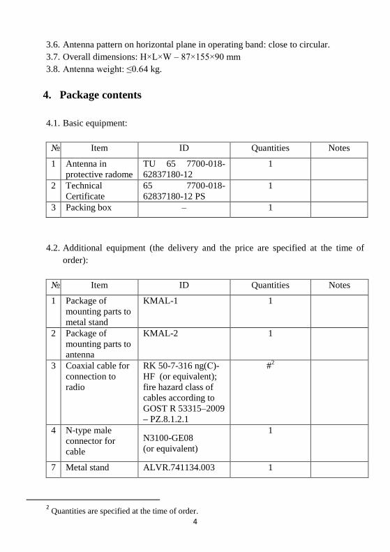
4. Package contents
4.1. Basic equipment:
№ Item ID Quantities Notes
1 Antenna in
protective radome
TU 65 7700-018-
62837180-12
1
2 Technical
Certificate
65 7700-018-
62837180-12 PS
1
3 Packing box – 1
4.2. Additional equipment (the delivery and the price are specified at the time of
order):
№ Item ID Quantities Notes
1 Package of
mounting parts to
metal stand
KMAL-1 1
2 Package of
mounting parts to
antenna
KMAL-2 1
3 Coaxial cable for
connection to
radio
RK 50-7-316 ng(С)-
HF (or equivalent);
fire hazard class of
cables according to
GOST R 53315–2009
– PZ.8.1.2.1
#2
4 N-type male
connector for
cable
N3100-GE08
(or equivalent)
1
7 Metal stand ALVR.741134.003 1
2 Quantities are specified at the time of order.

5
5. Design and Function
5.1. The antenna “АL3/800-3400” is
the non-symmetrical vertical
sleeve-type vibrator with the
symmetrical current supply in
the protective fiberglass radio-
transparent radome (Fig. 1).
Structurally the antenna contains
the base 1, the protective radio-
transparent radome 2, the
flanged female connector 3 for
the connection of the coaxial
cable to the radio. The antenna
supply is provided by the high-
frequency female connector 3.
5.2. The input antenna impedance – 50 Ohms. By means of the vertical vibrator’s leg
the antenna is grounded to the base 1, and then to the locomotive’s hull.
6. Safety Precautions
6.1. Only specially trained and familiar with mounting regulations staff can be
allowed to antenna mounting.
6.2. Antenna mounting should take place in depots with specially equipped areas.
6.3. During the antenna exploitation in cases of necessity of its examination or other
kinds of work no assembly is permitted when the rolling stock is under the
overhead contact system.
7. Pre-starting Procedure
7.1. The antenna installation should be in the strict adherence to mounting drawing
ALVR.464651.014 MCH (p. 12) and installation recommendations presented in
this section.
7.2. Please note! The manufacturer ensures antenna specifications reported in the
technical certificate if regulations 7.2.1-7.2.5 are adhered.
7.2.1. The antenna is directly mounted on a plane of the metal roof of the
rolling stock.
7.2.2. The distance from the antenna to the roof equipment must be no less
than 0.6 meters in all directions (fig. 3a).
7.2.3. The antenna must have the good electrical contact with the metal roof of
the locomotive.

6
7.2.4. It’s allowed:
the antenna installation on the locomotive’s roof made of the
dielectric material at the center of the preliminary fixed metal sheet
with dimensions 500 mm×500 mm at least;
the antenna installation on the metal stand with dimensions 500
mm×500 mm at least and the height relatively the horizontal
surface of the roof of 400 mm at most (fig. 2a);
the antenna installation on the metal stand welded across the roof
on each side with dimensions 200 mm×200 mm at least and the
height relatively the horizontal surface of the roof of 40 mm at
most (fig. 2b)3.
7.2.5. It is not allowed:
the antenna installation on the dielectric (non-metallic) surface;
the antenna installation on not cleaned metal surface covered by
paint, jointing compound, glue, etc.;
the antenna installation in the cross direction or angle wise
relatively moving direction (fig. 3b);
the application of painting and other coatings on the protective
fiberglass radio-transparent radome of the antenna.
3 If the metal stand is welded from 2 or 3 sides minimal dimensions must be increased up to 300 mm×400mm
and the connection plug must be hermetically sealed. The stand is made from the metal sheet 5-8 mm thick by an organization mounting the antenna.
Fig. 2

7
7.3. Antenna mounting without stand (the main option of mounting).
7.3.1. The antenna is mounted directly on the roof of the locomotive in the
longitudinal direction relative to the motion. Clean up the surface of the
roof down to the metal over the size of the antenna's base and tin the
surface. If the antenna is mounted on the roof made of the aluminum alloy,
after cleaning up it from the paint, the place of mounting must be
degreased but not be tinned.
7.3.2. Drill four holes around the perimeter with the diameter of 9 mm and one
central hole with the diameter of 47 mm for cables with connectors in the
selected place of mounting according to ALVR.464651.014 MCH. The
edge of the central hole should be processed with the file and then with the
sandpaper.
7.3.3. During installing of the antenna on the mounting location it is not allowed:
contacting of coaxial cables with the edge of the central hole in
order to avoid the damage during the operation;
contacting the protective tube of the antenna for the cable input
for the connection to the navigation system with the edge of the
central hole in order to avoid the damage during the operation;
bending cable RK 50-7-316 ng(C)-HF with radius of less than
200 mm;
bending cable RK 50-3-38 with radius of less than 90 mm.
7.3.4. Pull the cable RK50-7-316 ng(C)-HF (or equivalent) with the connector
N3100-GE08 through the central hole and connect them to the connector
N864L4-0000 on the antenna. Mount the antenna to the prepared surface
Fig. 3

8
to match fixing holes so that the inclined portion of the radome was
directed in the direction of movement. Ensure that connected cables are
not tensioned along its entire length.
7.3.5. Fasten antenna's base on the surface using the mounting kit KMAL-2
(available on request) by alternately and evenly tightening the nuts on the
perimeter according to assembly drawing ALVR.464651.014 MCH.
7.4. Antenna mounting with optional stand (available on request).
7.4.1. Mounting of the antenna via the stand ALVR.74134.003 is performed by
welding along the perimeter to the metal roof of the locomotive (or other
surface designed to be mounted) by the technology in accordance with the
material of the surface being installed. Pre-mark the hole for the cable and
check that the distance between the edge of the front side of the antenna
base and the center of the hole is 52 mm. Drill a hole with the diameter 47-
50 mm. Install the stand to the roof and align the holes in the roof and the
base. Weld the stand to the roof.
7.4.2. Upon the completion of welding remove the scale from the surface of the
platform. Pull the cable RK50-7-316 ng(C)-HF (or equivalent) with the
connector N3100-GE08 through the central hole and connect them to the
connector N864L4-0000 on the antenna.
7.4.3. Mount the antenna on the metal stand so that the holes in the base of the
antenna coincide with the mounting studs of the stand and the inclined
portion of the radome was oriented in the direction of the movement.
Fasten the antenna on the stand with the washers and nuts from the
mounting kit KMAL-1 by alternately and evenly tightening the nuts on the
perimeter of the base according to assembly drawing ALVR.464651.014
MCH.
7.5. For additional sealing-in, the application of specialized sealants, for example
Pentelast ® -1130 (or similar), is possible. The sealant is applied around the base
of the antenna and mounting bolts around the head, according to the instructions
for use. If sealants of other brands are used, look for the compliance of their
physical and chemical properties of the operating conditions of the locomotive
antenna.
Please note! If it impossible to adhere with all antenna installation requirements
contained in this technical certificate, the antenna installation is performed in
agreement with the manufacturer.
9
8. Maintenance
8.1. The maintenance of the antenna is not required. 8.2. In the case of mechanical damages of the radome the antenna should be
replaced.
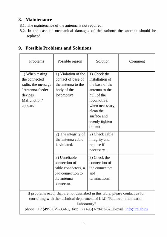
9. Possible Problems and Solutions
Problems Possible reason Solution Comment
1) When testing
the connected
radio, the message
"Antenna-feeder
devices
Malfunction"
appears
1) Violation of the
contact of base of
the antenna to the
body of the
locomotive.
1) Check the
installation of
the base of the
antenna to the
hull of the
locomotive,
when necessary,
clean the
surface and
evenly tighten
the nut.
2) The integrity of
the antenna cable
is violated.
2) Check cable
integrity and
replace if
necessary.
3) Unreliable
connection of
cable connectors, a
bad connection to
the antenna
connector.
3) Check the
connection of
the connectors
and
terminations.
If problems occur that are not described in this table, please contact us for
consulting with the technical department of LLC "Radiocommunication
Laboratory"
phone.: +7 (495) 679-83-61, fax: +7 (495) 679-83-62, E-mail: [email protected]
10
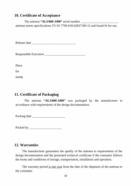
10. Certificate of Acceptance
The antenna “AL3/800-3400” serial number ________________________
antenna meets specifications TU 65 7700-018-62837180-12 and found fit for use.
Release date ____________________________
Responsible Executive __________________________
Place
for
stamp
11. Certificate of Packaging
The antenna “AL3/800-3400” was packaged by the manufacturer in
accordance with requirements of the design documentation.
Packing date _____________________
Packed by _____________________
12. Warranties
The manufacturer guarantees the quality of the antenna to requirements of the
design documentation and the presented technical certificate if the consumer follows
the terms and conditions of storage, transportation, installation and operation.
The warranty period is one year from the date of the shipment of the antenna to
the consumer.
11
13. Reclamation History
The claim to the reclamation is performed according to GOST V15.703-78.
Item,
ID
Date of
Reclamation
Reclamation
Summary
Mark of
Allowance of
Reclamation
Appointment,
Name, Signature
of Responsible
Executive
Notes

12
14. Mounting Drawing