technical compliance statement emc test report
TRANSCRIPT

Technical Compliance Statement EMC Test Report
For the following information Ref. File No.: C1M1803154 Product : UPS (Uninterruptible Power Supply) Model Number : (1)SMT750RMI2UC (2)SMT750IC Series Model : (1)SMT750RMI2UCXXXXXXXXXX (2)SMT750ICXXXXXXXXXX (X=A-Z, a-z, 0-9, +, *, #, _, - or blank) Brand Name : APC by Schneider-Electric Applicant : American Power Conversion Holding Inc.,
Taiwan Branch Manufacturer : American Power Conversion Holding Inc.,
Taiwan Branch Standards :
EN 62040-2:2006+ AC:2006 (IEC 62040-2:2005), Category C2 AS 62040.2:2008 (CISPR 22: 2008, EN 61000-3-2:2014 Class A, IEC 61000-4-2:2008, IEC 61000-4-3:2010, IEC 61000-4-4:2012, IEC 61000-4-5:2014 +A1:2017, IEC 61000-4-6:2013, IEC 61000-4-8:2009, IEC 61000-2-2:2002) We hereby certify that the above product has been tested by us with the listed stan-dards and found in compliance with the council EMC directive 2014/30/EU. The test data and results are issued on the EMC test report no. EM-E180111. Signature __________________________ Alex Deng/Deputy Manager Date: 2018. 03. 23 Test Laboratory: Audix Technology Corporation, EMC Department TAF Accreditation No.: 1724 Web Site: www.audixtech.com The statement is based on a single evaluation of one sample of the above-mentioned products. It does not imply an assessment of the whole production and does not permit the use of the test lab logo.

Page 1 of 88
Audix Technology Corporation Report No.: EM-E180111
TEST REPORT
UPS (Uninterruptible Power Supply) Model Number: (1)SMT750RMI2UC (2)SMT750IC Series Model: (1)SMT750RMI2UCXXXXXXXXXX (2)SMT750ICXXXXXXXXXX (X=A-Z, a-z, 0-9, +, *, #, _, - or blank)
Brand: APC by Schneider-Electric
Applicant for: American Power Conversion Holding Inc., Taiwan Branch
3F., No.205, Sec. 3, Beixin Rd. Xindian District, New Taipei City 23143, Taiwan
Prepared by: Audix Technology Corporation, EMC Department
No. 53-11, Dingfu, Linkou Dist., New Taipei City 244, Taiwan
File No. : C1M1803154 Report No. : EM-E180111 Date of Report : 2018. 03. 23
The test report is based on a single evaluation of one sample of the above-mentioned products. It does not imply an assessment of the whole production and does not permit the use of the test lab logo. The report must not be used by the client to claim product certification, approval, or endorsement by NVLAP, NIST, TAF or any government agencies.
TESTING NVLAP LAB CODE 200077-0

Page 2 of 88
Audix Technology Corporation Report No.: EM-E180111
Test Report
Applicant : American Power Conversion Holding Inc.,
Taiwan Branch Manufacturer : American Power Conversion Holding Inc.,
Taiwan Branch EUT Description
(1) Product : UPS (Uninterruptible Power Supply) (2) Model Number : (1)SMT750RMI2UC (2)SMT750IC (3) Series Model : (1)SMT750RMI2UCXXXXXXXXXX (2)SMT750ICXXXXXXXXXX (X=A-Z, a-z, 0-9, +, *, #, _, - or blank) (3) Brand : APC by Schneider-Electric (4) Power Rating : Input: 220-240VAC, 50/60Hz Output: 220-240VAC, 50/60Hz
Applicable Standards: EN 62040-2:2006+ AC:2006 (IEC 62040-2:2005), Category C2 AS 62040.2:2008 (CISPR 22: 2008, EN 61000-3-2:2014 Class A, IEC 61000-4-2:2008, IEC 61000-4-3:2010, IEC 61000-4-4:2012, IEC 61000-4-5:2014 +A1:2017, IEC 61000-4-6:2013, IEC 61000-4-8:2009, IEC 61000-2-2:2002) The device described above was tested by Audix Technology Corporation to determine the maximum emission levels emanating from the device, its ensured severity levels, and per-formance criterion. All of the tests were requested by the applicant and the results thereof based upon the information that the applicant provided to us. We, Audix Technology Cor-poration assumes full responsibility for the accuracy and completeness of these measure-ments. Also, this report shows that the EUT is technically compliance with the requirements of EN 62040-2 standards.
This report applies to above tested sample only and shall not be reproduced in part without written approval of Audix Technology Corporation. Date of Report: 2018. 03. 23 __________________________ Reviewed by: __________________________ (Ariel Chen/Administrator) Approved by: __________________________ (Alex Deng/Deputy Manager)

Page 3 of 88
Audix Technology Corporation Report No.: EM-E180111
Table of Content
1. Revision of Test Report .............................................................................................. 6 2. Summary of Test Result ............................................................................................. 7 2.1. Test Result .................................................................................................................... 7 2.2. Description of Performance Criteria ............................................................................... 9 2.3. Description of Test Firm .............................................................................................. 10 3. General Information .................................................................................................. 11 3.1. Description of Application ............................................................................................ 11 3.2. Description of the EUT ................................................................................................ 12 3.3. Highest Frequency within EUT .................................................................................... 12 3.4. List of Key Components of EUT .................................................................................. 13 3.5. Determination of Worse Case Operating Modes ......................................................... 14 3.6. Final Test Configuration Mode ..................................................................................... 15 4. Measurement Arrangement ...................................................................................... 16 4.1. Equipment and cables arrangement ............................................................................ 16 4.2. Method of Exercising EUT ........................................................................................... 19 4.3. List of Supported Units under Test .............................................................................. 20 4.4. List of Used Cables under Test ................................................................................... 21 5. Measurement of Conducted Emissions................................................................... 22 5.1. List of Test Instruments ............................................................................................... 22 5.2. Test Setup ................................................................................................................... 23 5.3. Applicable Limits .......................................................................................................... 24 5.4. Measurement Procedure ............................................................................................. 26 5.5. Measurement Result ................................................................................................... 28 6. Measurement of Radiated Emissions ...................................................................... 34 6.1. List of Test Instruments ............................................................................................... 34 6.2. Test Setup ................................................................................................................... 35 6.3. Applicable Limits .......................................................................................................... 36 6.4. Measurement Procedure ............................................................................................. 36 6.5. Measurement Result ................................................................................................... 37 7. Measurement of Input Current Harmonics .............................................................. 43 7.1. List of Test Instruments ............................................................................................... 43 7.2. Test Setup ................................................................................................................... 43 7.3. Applicable Standard and Limits ................................................................................... 44 7.4. Measurement Procedure ............................................................................................. 44 7.5. Measurement Result ................................................................................................... 45 8. Electrostatic Discharge Immunity Test ................................................................... 47 8.1. List of Test Instruments ............................................................................................... 47 8.2. Test Setup ................................................................................................................... 47 8.3. Applicable Standard and Test Specification ................................................................ 47 8.4. Measurement Procedure ............................................................................................. 48 8.5. Test Result .................................................................................................................. 49

Page 4 of 88
Audix Technology Corporation Report No.: EM-E180111
9. Radiated, Radio-frequency, Electromagnetic Field Immunity Test ....................... 50 9.1. List of Test Instruments ............................................................................................... 50 9.2. Test Setup ................................................................................................................... 50 9.3. Applicable Standard and Test Specification ................................................................ 51 9.4. Measurement Procedure ............................................................................................. 51 9.5. Test Result .................................................................................................................. 52 10. Electrical fast transient/burst Immunity Test .......................................................... 53 10.1. List of Test Instruments ............................................................................................... 53 10.2. Test Setup ................................................................................................................... 53 10.3. Applicable Standard and Test Specification ................................................................ 54 10.4. Measurement Procedure ............................................................................................. 54 10.5. Test Result .................................................................................................................. 55 11. Surge Immunity Test ................................................................................................. 56 11.1. List of Test Instruments ............................................................................................... 56 11.2. Test Setup ................................................................................................................... 56 11.3. Applicable Standard and Test Specification ................................................................ 57 11.4. Measurement Procedure ............................................................................................. 57 11.5. Test Result .................................................................................................................. 58 12. Immunity to Conducted Disturbances, Induced by Radio-Frequency Field Immunity Test ..................................................................................................................... 60 12.1. List of Test Instruments ............................................................................................... 60 12.2. Test Setup ................................................................................................................... 60 12.3. Applicable Standard and Test Specification ................................................................ 61 12.4. Measurement Procedure ............................................................................................. 62 12.5. Test Result .................................................................................................................. 63 13. Power Frequency Magnetic Field Immunity Test .................................................... 64 13.1. List of Test Instruments ............................................................................................... 64 13.2. Test Setup ................................................................................................................... 64 13.3. Applicable Standard and Test Specification ................................................................ 64 13.4. Measurement Procedure ............................................................................................. 65 13.5. Test Result .................................................................................................................. 66 14. Low Frequency Signals Immunity Test ................................................................... 67 14.1. List of Test Instruments ............................................................................................... 67 14.2. Test Setup ................................................................................................................... 67 14.3. Applicable Standard and Test Specification ................................................................ 68 14.4. Measurement Procedure ............................................................................................. 68 14.5. Test Result .................................................................................................................. 69 15. Measurement Uncertainty List ................................................................................. 70 16. Photographs .............................................................................................................. 73 16.1. Conducted Emissions Measurement ........................................................................... 73 16.2. Radiated Emissions Measurement .............................................................................. 74 16.3. Input Current Harmonics Measurement ....................................................................... 75 16.4. Electrostatic Discharge Immunity Test ........................................................................ 76 16.5. Radiated, Radio-Frequency, Electromagnetic Field Immunity Test ............................. 83

Page 5 of 88
Audix Technology Corporation Report No.: EM-E180111
16.6. Electrical Fast Transient/Burst Immunity Test ............................................................. 84 16.7. Surge Immunity Test ................................................................................................... 85 16.8. Immunity to Conducted Disturbances Induced by RF Fields ....................................... 86 16.9. Power Frequency Magnetic Field Immunity Test ......................................................... 87 16.10. Low Frequency Signals Immunity Test .................................................................. 87 16.11. Partner System ...................................................................................................... 88 APPENDIX I (Photos of EUT) APPENDIX II (Data Pretest)

Page 6 of 88
Audix Technology Corporation Report No.: EM-E180111
1. Revision of Test Report Issued Date Revision Summary Report Number
2018. 03. 23 Original Report. EM-E180111

Page 7 of 88
Audix Technology Corporation Report No.: EM-E180111
2. Summary of Test Result
2.1. Test Result
Emission
Test Item Referred Standard Limit Result
Conducted emissions at AC mains power port
EN 62040-2:2006 + AC:2006 (CISPR 22:2008)
Category C2 UPS
Pass
Margin 19.13 dB at 0.150 MHz
Conducted emissions at DC mains power port
EN 62040-2:2006 + AC:2006 (CISPR 22:2008)
Category C2 UPS N/A (Note 5)
Conducted emissions at signal and telecommu-nication ports
EN 62040-2:2006 + AC:2006 (CISPR 22:2008)
Category C2 UPS N/A (Note 6)
Radiated emissions (30 – 1000MHz)
EN 62040-2:2006 + AC:2006 (CISPR 22:2008)
Category C2 UPS
Pass
Margin 6.07 dB at 224.998 MHz
Low-frequency emission Input current harmonic EN 61000-3-2:2014 Class A Pass
Note : 1. N/A is an abbreviation for Not Applicable 2. Special measures: None 3. Decision and justification not to measure: None 4. The EN 62040-2 emission measurement results are deemed satisfactory evidence of com-
pliance with AS 62040.2 regulations. 5. According to the manufacturer’s specification may not use the AC output Cable exceed
10m, it’s unnecessary to test for AC output Cable. 6. According to the manufacturer’s specification may not use the Signal Cable exceed 10m,
it’s unnecessary to test for signal and telecommunication ports.

Page 8 of 88
Audix Technology Corporation Report No.: EM-E180111
Immunity
Test Item Basic Standard Standard Criteria
EUT Criteria Result
Electrostatic discharge EN 62040-2:2006 + AC:2006 (IEC 61000-4-2:2008)
B A Pass
Radiated, Radio-frequency, electromagnetic field
EN 62040-2:2006 + AC:2006 (IEC 61000-4-3:2010)
A A Pass
Electrical fast transient/burst EN 62040-2:2006 + AC:2006 (IEC 61000-4-4:2012)
B A Pass
Surge at AC power port
EN 62040-2:2006 + AC:2006 (IEC 61000-4-5:2014 +A1:2017)
B A Pass
Surge at signal and control ports
EN 62040-2:2006 (IEC 61000-4-5:2014 +A1:2017)
B A Pass
Immunity to conducted dis-turbances, induced by ra-dio-frequency fields
EN 62040-2:2006 + AC:2006 (IEC 61000-4-6:2013)
A A Pass
Power frequency magnetic field
EN 62040-2:2006 + AC:2006 (IEC 61000-4-8:2009)
B A Pass
Low frequency signals test EN 62040-2:2006 + AC:2006 (IEC 61000-2-2:2002)
A A Pass
Note : 1. N/A is an abbreviation for Not Applicable 2. Special measures: None 3. Decision and justification not to measure: None

Page 9 of 88
Audix Technology Corporation Report No.: EM-E180111
2.2. Description of Performance Criteria The Equipment shall, as a minimum, comply with the immunity limits of 3.2 to 3.6. The per-formance criteria adequate for U.P.S. is given in the following table.
Criterion A Criterion B
Output characteristics Static tolerances of IEC 62040-3
Dynamic tolerances of IEC 62040-3
External and internal indica-tions and metering
Change only during test Change only during test
Control signals to external devices
No Change Change according to the mode of operation
Mode of operation No Change Change only temporarily
The test shall be made with the U.P.S. in the following conditions: - rated input voltage; - normal mode of operation; - linear load at rated active output power. The UPS shall be specified with the proper level in case of different levels of performance criteria.

Page 10 of 88
Audix Technology Corporation Report No.: EM-E180111
2.3. Description of Test Firm
Name of Test Firm
Audix Technology Corporation / EMC Department No. 53-11, Dingfu, Linkou Dist., New Taipei City 244, Taiwan Tel: +886-2-26092133 Fax: +886-2-26099303 Website : www.audixtech.com Contact e-mail: [email protected]
Accreditations
The laboratory is accredited by following organizations under ISO/IEC 17025:2005
(1) NVLAP (USA) NVLAP Lab Code 200077-0
(2) TAF (Taiwan) No. 1724
Test Facilities
(1) No. 3 Shielded Room (2) No. 6 Open Test Site (3) No. 2 EMS Test Room (4) No. 3 EMS Test Room

Page 11 of 88
Audix Technology Corporation Report No.: EM-E180111
3. General Information
3.1. Description of Application
Applicant American Power Conversion Holding Inc., Taiwan Branch 3F., No.205, Sec. 3, Beixin Rd. Xindian District, New Taipei City 23143 Taiwan
Manufacturer American Power Conversion Holding Inc., Taiwan Branch 3F., No.205, Sec. 3, Beixin Rd. Xindian District, New Taipei City 23143 Taiwan
Product UPS (Uninterruptible Power Supply)
Brand APC by Schneider-Electric
Model Number (1)SMT750RMI2UC (2)SMT750IC
The difference between above models please refer to the following table.
Series Model (1)SMT750RMI2UCXXXXXXXXXX (2)SMT750ICXXXXXXXXXX (X=A-Z, a-z, 0-9, +, *, #, _, - or blank)
Table: Model different list Appearance PCBA Power
transformer MOSFETInput rating
AC 220-240V, 50/60Hz
Output rating
SMT750RMI2UC Rack mount 640-3705C-Z 430-1030 -
4A 750VA/500W SMT750IC Tower 640-3100C-Z 430-9112A 4A 750VA/500W
Model No.
Difference

Page 12 of 88
Audix Technology Corporation Report No.: EM-E180111
3.2. Description of the EUT
Test Model (1)SMT750RMI2UC (2)SMT750IC
Serial Number N/A
Power Rating Input: 220-240VAC, 50/60Hz Output: 220-240VAC, 50/60Hz
Firmware Version N/A
Sample Status Production
Date of Receipt 2018. 02. 02
Date of Test 2018. 02. 02 ~ 03. 22
I/O Ports List
Model: SMT750RMI2UC AC In x1 AC Out x4 Console x1 Console USB 1 x1 Console USB 2 x1 Universal I/O 1 x1 Universal I/O 2 x1 LAN In x2 USB In x1 Serial x1
Model: SMT750IC AC In x1 AC Out x6 Console x1 Console USB 1 x1 Console USB 2 x1 Universal I/O 1 x1 Universal I/O 2 x1 LAN In x2 USB In x1 Serial x1
Accessories Supplied
USB Cable LAN Cable
3.3. Highest Frequency within EUT
The highest frequency is above 108MHz of EUT.
Page 13 of 88
Audix Technology Corporation Report No.: EM-E180111
3.4. List of Key Components of EUT
Component Supplier Model/Type Description
Battery Module (2S1P, DC 24V, 7Ah / 7.2Ah)
Hitachi Chemical GP1272F2 7.2AH (Test Used)
Panasonic Industrial Co. LC-R127R2P1 7.2AH
BB Group Company BP7-12 7AH
Exide Industries EP1229W(N) 7AH Kung Long WP7,2-12 7.2AH Powerson Baotou ROC Storage battery Co., Ltd
MF12-7H 7AH
Japan Storage Battery Co., Ltd PE12V7.2 7.2AH
Shenzhen Center Power Tech.
CP1270 7AH
CSB Battery GP1272F2 7.2AH

Page 14 of 88
Audix Technology Corporation Report No.: EM-E180111
3.5. Determination of Worse Case Operating Modes According to the specification, the EUT was estimated to determine the highest emissions by following configurations:
Test Item Test Model Input power Operating Mode
Conducted emissions at AC mains power port
SMT750RMI2UC AC 230V, 50Hz Online Mode Green Mode
DC 24V Battery Mode
SMT750IC AC 230V, 50Hz Online Mode Green Mode
DC 24V Battery Mode
Conducted emissions at signal and telecommu-nication ports
SMT750RMI2UC AC 230V, 50Hz
Online Mode, NMC LAN (10Mbps)
Online Mode, NMC LAN (100Mbps)
Online Mode, LCE LAN (100Mbps)
SMT750IC AC 230V, 50Hz
Online Mode, NMC LAN (10Mbps)
Online Mode, NMC LAN (100Mbps)
Online Mode, LCE LAN (100Mbps)
Radiated emission
(30 – 1000MHz)
SMT750RMI2UC AC 230V, 50Hz Online Mode
Green Mode DC 24V Battery Mode
SMT750IC AC 230V, 50Hz Online Mode
Green Mode DC 24V Battery Mode
Low-frequency emission Input current harmonic SMT750RMI2UC AC 230V/50Hz Online Mode
Electrostatic discharge & Radiated, Radio-frequency, electromagnetic field
SMT750RMI2UC AC 230V/50Hz Online Mode
Battery Mode
Other Immunity tests SMT750RMI2UC AC 230V/50Hz Online Mode

Page 15 of 88
Audix Technology Corporation Report No.: EM-E180111
3.6. Final Test Configuration Mode The worst showed as following configuration was tested and recorded in the report.
Test Item Test Model Input power Operating Mode
Conducted emissions at AC mains power port SMT750RMI2UC
AC 230V, 50Hz Online Mode Green Mode
DC 24V Battery Mode
Conducted emissions at signal and telecommu-nication ports
SMT750RMI2UC AC 230V, 50Hz
Online Mode, NMC LAN (10Mbps)
Online Mode, NMC LAN (100Mbps)
Online Mode, LCE LAN (100Mbps)
Radiated emission
(30 – 1000MHz) SMT750RMI2UC
AC 230V, 50Hz Online Mode Green Mode
DC 24V Battery Mode
Low-frequency emission Input current harmonic SMT750RMI2UC AC 230V/50Hz Online Mode
Electrostatic discharge & Radiated, Radio-frequency, electromagnetic field
SMT750RMI2UC AC 230V/50Hz Online Mode
Other Immunity tests SMT750RMI2UC AC 230V/50Hz Online Mode

Page 16 of 88
Audix Technology Corporation Report No.: EM-E180111
4. Measurement Arrangement
4.1. Equipment and cables arrangement
Connection Diagram of EUT and Peripheral Devices For conducted and radiated tests
For Model: SMT750RMI2UC
AC POWER SOURCE
UPS (Uninterruptible Power Supply)
(EUT)
Console USB 1
AC IN
USB
3
5
10
LAN
NOTEBOOK PC (C)
3Console USB 2
9
(Out of Test Ares)
Partner System
AC Out*2 1*2 BULB LOAD (A)
Universal I/O 1 2
2Universal I/O 2
LAN 8
Serial 6
Console 7
4
WIRELESS ROUTER (D)
NOTEBOOK PC
(B)
AC Out*2 1*2

Page 17 of 88
Audix Technology Corporation Report No.: EM-E180111
For Model: SMT750IC
AC POWER SOURCE
UPS (Uninterruptible Power Supply)
(EUT)
Console USB 1
AC IN
USB
3
5
10
LAN
NOTEBOOK PC (C)
3Console USB 2
9
(Out of Test Ares)
Partner System
AC Out*2 1*2
BULB LOAD (A)
Universal I/O 1 2
2Universal I/O 2
LAN 8
Serial 6
Console 7
4
WIRELESS ROUTER (D)
NOTEBOOK PC
(B)
AC Out*4 1*4

Page 18 of 88
Audix Technology Corporation Report No.: EM-E180111
Connection Diagram of EUT and Peripheral Devices For harmonics, flicker and immunity tests
AC POWER SOURCE
UPS (Uninterruptible Power Supply)
(EUT)
Console USB 1
AC IN
USB
2LAN
10
3
Console USB 2
9
AC Out*2 1
BULB LOAD #1 (A)
Universal I/O 1
4
4
Universal I/O 2
LAN 8
NOTEBOOK PC (C)
Serial 6
Console 7
AC Out*2 1
BULB LOAD #2 (B)
WIRELESS ROUTER
(D)
5
5

Page 19 of 88
Audix Technology Corporation Report No.: EM-E180111
4.2. Method of Exercising EUT
The methods for exercising the EUT during the emission tests.
1. Turn on the power of all equipments.
2. Setup the notebook pc to drive the EUT through the UPS’s software driver.
3. Data was communicated between the notebook pc and EUT through the USB and LAN interface cable. The notebook pc displayed the test software and rating of the EUT by windows XP.
4. Set EUT under line or battery or green mode.
5. The AC outputs of EUT was linked to bulb loads with full load (500W).
6. EUT sent and received messages to/from partner notebook pc with wireless router through the LAN interface cable.
7. The other peripheral devices were driven and operated in turn during all testing.
The methods for exercising the EUT during the Harmonics, Flicker and Immunity tests.
1. Turn on the power of all equipments.
2. Setup the notebook pc to drive the EUT through the UPS’s software driver.
3. Data was communicated between the notebook pc and EUT through the USB and LAN-RS232 interface cable. The notebook pc displayed the test software and rating of the EUT by windows XP.
4. Set EUT under line or battery mode.
5. The AC outputs of EUT was linked to bulb loads with full load (500W).
6. EUT sent and received messages to/from with wireless router through the LAN inter-face cable.
7. The other peripheral devices were driven and operated in turn during all testing.

Page 20 of 88
Audix Technology Corporation Report No.: EM-E180111
4.3. List of Supported Units under Test
Item Product Brand Model No. Serial No. Approval
For Conducted and Radiated test
A Bulb Load (500W)
Audix N/A N/A N/A
B Notebook PC DELL TDC20090005 N/A By DoC
Partner System C Notebook PC Lenovo TP00034A 895097 By DoC
D Wireless Router D-Link DIR-868L R3WE1D7002319 FCC ID: KA2IR868LA1
For Harmonic、Flicker and Immunity Tests
A Bulb Load (500W)
Audix N/A N/A N/A
B Notebook PC DELL TDC20090005 N/A By DoC
C Wireless Router D-Link DIR-868L R3WE1D7002319 FCC ID: KA2IR868LA1

Page 21 of 88
Audix Technology Corporation Report No.: EM-E180111
4.4. List of Used Cables under Test
Item Type Qty. Length (m)
Shielding (Yes/No)
Cores (Qty.) Remark
For Conducted and Radiated test 1 Power Cord 4/6 1.8 No 0 Provided by LAB
2 LAN Cable 2 2.0 No 0 Accessory of EUT
3 USB Cable 2 1.8 Yes 0 Accessory of EUT
4 LAN to RS232 Ca-ble 1 2.0 Yes 0 Provided by LAB
5 USB Cable 1 1.8 Yes 0 Accessory of EUT
6 USB Cable 1 1.8 Yes 0 Provided by LAB
7 USB Cable 1 1.8 Yes 0 Provided by LAB
8 LAN Cable 1 10.0 No 0 Provided by LAB
9 LAN Cable 1 1.8 No 0 Provided by LAB
10 AC Power Cord (3C) 1 1.8 No 0 Provided by LAB
11 AC Power Cord 2 1.8 No 0 Provided by LAB for above supported units
For Harmonic、Flicker and Immunity Tests 1 Power Cord 4 1.8 No 0 Provided by LAB
2 LAN to RS232 Ca-ble 1 2.0 No 0 Accessory of EUT
3 USB Cable 1 1.8 Yes 0 Accessory of EUT
4 USB Cable 2 1.8 Yes 0 Accessory of EUT
5 LAN Cable 2 4.0 No 0 Accessory of EUT
6 Data Cable 1 1.8 No 0 Provided by LAB
7 Data Cable 1 1.8 No 0 Provided by LAB
8 LAN Cable 1 1.5 No 0 Provided by LAB
9 LAN Cable 1 1.8 No 0 Provided by LAB
10 AC Power Cord (3C) 1 1.8 No 0 Provided by LAB
11 AC Power Cord 2 1.8 No 0 Provided by LAB for above supported units

Page 22 of 88
Audix Technology Corporation Report No.: EM-E180111
5. Measurement of Conducted Emissions
5.1. List of Test Instruments
For AC mains power port use
Item Equipment Manufacturer Model No. Serial No. Cal. Date Cal. Interval
1 Test Receiver R & S ESR3 101772 2018. 01. 17 1 Year
2 A.M.N. R&S KNW-244C 8-1373-5 2017. 04. 13 1 Year
3 L.I.S.N. Kyoritsu KNW-407 8-1370-9 2018. 01. 30 1 Year
4 Pulse Limiter R & S ESH3-Z2 100041 2018. 01. 15 1 Year
5 Signal Cable CDM Electron-ics, Inc. RG-142 CE-02 2017. 02. 08 1 Year
6 Digital Ther-mo-Hygro Meter YICHUN TFC-9606 No.3 S/R 2017. 04. 20 1 Year
7 Test Software Audix e3 V.120703a N.C.R. N.C.R.
For signal and telecommunication ports use
Item Equipment Manufacture Model No. Serial No. Cal. Date Cal. Interval
1 Test Receiver R & S ESR3 101772 2018. 01. 17 1 Year
2 A.M.N. R&S KNW-244C 8-1373-5 2017. 04. 13 1 Year
3 L.I.S.N. Kyoritsu KNW-407 8-1370-9 2018. 01. 30 1 Year
4 Signal Cable CDM Electron-ics, Inc. RG-142 CE-02 2017. 02. 08 1 Year
5 Impedance Sta-bilization Net-work
TESEQ ISN T800 30331 2017. 09. 05 1 Year
6 Digital Ther-mo-Hygro Meter YICHUN TFC-9606 No.3 S/R 2017. 04. 20 1 Year
7 Test Software Audix e3 V.120703a N.C.R. N.C.R.

Page 23 of 88
Audix Technology Corporation Report No.: EM-E180111
5.2. Test Setup
The EUTs and test equipment were configured in accordance with the requirement of EN 62040-2 Annex A.6.4.
For AC mains power port
For signal and telecommunication ports
EUT, local AE and associated cabling; and metal surfaces other than the RGP≧80cm
Page 24 of 88
Audix Technology Corporation Report No.: EM-E180111
5.3. Applicable Limits
Limits of mains terminal interference voltage frequency range 0,15 MHz to 30 MHz for
category C1 UPS and category C2 UPS equipment
Frequency Range (MHz)
Limits dB(μV)
Category C1 UPS Category C2 UPS Quasi-peak Average Quasi-peak Average
0.15 – 0.50 66 to 56a 56 to 46a 79 66
0.50 – 5b 56 46 73 60
5 – 30 60 50 73 60 a. The limit decreases linearly with the logarithm of the frequency. b. The lower limit shall apply at the transition frequency.
Limits of mains terminal interference voltage frequency range 0,15 MHz to 30 MHz for
Category C3 UPS equipment
UPS rated output current
A
Frequency range (MHz)
Limits dB(μV)
Category C3 UPS Quasi-peak Average
>16 – 100
0.15 – 0.50 b 100 90
0.50 – 5.0b 86 76
5.0 – 30.0 90 to 70a 80 to 60a
>100
0.15 – 0.50b 130 120
0.50 – 5.0b 125 115
5.0 – 30.0 115 105 c. The limits decrease linearly with the logarithm of the frequency. d. The lower limit shall apply at the transition frequency.
Limits of a.c. output interference voltage
The limits in Tables 1 and 2 apply. An allowance of +14 dB is permitted for conducted disturbances at the output of the UPS as specified in Tables 1 and 2, except for C3 greater that 100 A where no increase is allowed. These limits only apply to UPS where the output cable, as declared by the manufacturer, in his users’ instructions, can ex-ceed 10 m in length.

Page 25 of 88
Audix Technology Corporation Report No.: EM-E180111
Limits of signal and telecommunication ports
For ports intended for connection to the public switched telecommunication network (PSTN), the test methods and limits of CISPR 22 apply.
Port Frequency range Limits Basic standard
Signal, control
0,15 MHz to 0,5 MHz 40-30 dB(μA) quasi-peak
CISPR 22 Class B
Limit decreasing linearly with logarithm frequency
30-20 dB(μA) average
0,5 MHz to 30 MHz
30 dB(μA) quasi-peak 20 dB(μA) average

Page 26 of 88
Audix Technology Corporation Report No.: EM-E180111
5.4. Measurement Procedure
For AC mains power port
The method of EN 62040-2 Annex A.6 was used.
Setup the EUTs and associated equipment described as clause 4.1, and they were lo-cated 40cm from the vertical conducting plane.
Connect the EUT power cord to the main A.M.N and associated equipment to the second A.M.N. All ports of the A.M.N not connecting to the measuring equipment was terminated into 50 ohm resistive load.
Connect receiver tuner port to an AAN that is bonded to the RGP.
Setup the resolution bandwidth of the test receiver as section 5.3 defined.
Operate the EUT system as described in clause 4.2.
For the exploratory measurement, determine the highest emission amplitude relative to the limit on each of the EUT power cord with the peak detector by each of the EUT oper-ation over the specified frequency range and record it, and then
For final measurement, select the EUT operation mode that produced the highest ampli-tude in the exploratory measurement to determine the highest emissions with each spe-cified detector and record it. All of the current-carrying conductors of each of the EUT power cords, except the ground conductor, must be measured over the specified fre-quency range.
The measurement result was calculated by following formula:
Emission Level = Reading (Receiver) + Factor (A.M.N) + Insertion Loss (Pulse Limiter) + Cable Loss
If the average limit is met when using a Quasi-Peak detector receiver, the EUT is deemed to meet both limits and measurement with the average detector is unnecessary.

Page 27 of 88
Audix Technology Corporation Report No.: EM-E180111
For signal and telecommunication ports The method of EN 62040-2 Annex C and CISPR 22 clause 9 were used.
Setup the EUTs and associated equipment described as clause 4.1, and they were lo-cated 40cm from the vertical conducting plane.
Connect wired network port between EUT and AE through the AAN.
Setup the resolution bandwidth of the test receiver as section 5.3 defined.
Operate the EUT system as described in clause 4.2.
For the exploratory measurement, determine the highest emission amplitude relative to the limit on each of the EUT LAN port with the peak detector by each of the transmission rate over the specified frequency range and record it, and then
For final measurement, select the worst network port that produced the highest ampli-tude in the exploratory measurement to determine the highest emissions with each spe-cified detector and record it. All of the transmission rates must be measured over the specified frequency range.
The measurement result was calculated by following formula:
Emission Level = Reading (Receiver) + Factor (AAN) + Insertion Loss (Pulse Limiter) + Cable Loss
If the average limit is met when using a Quasi-Peak detector receiver, the EUT is deemed to meet both limits and measurement with the average detector is unnecessary.

Page 28 of 88
Audix Technology Corporation Report No.: EM-E180111
5.5. Measurement Result
The following data are the worst emissions based on the prescan measurement result.
Result for AC Mains Power Port
Test Date 2018. 02. 02 Environment 24ºC, 61%
Input Power AC 230V, 50Hz Test Phase Neutral
Tested By Ghost Test Result Pass
Test Mode Online Mode Test Model SMT750RMI2UC

Page 29 of 88
Audix Technology Corporation Report No.: EM-E180111
Test Date 2018. 02. 02 Environment 24ºC, 61%
Input Power AC 230V, 50Hz Test Phase Line
Tested By Ghost Test Result Pass
Test Mode Online Mode Test Model SMT750RMI2UC

Page 30 of 88
Audix Technology Corporation Report No.: EM-E180111
Test Date 2018. 02. 02 Environment 24ºC, 61%
Input Power AC 230V, 50Hz Test Phase Neutral
Tested By Ghost Test Result Pass
Test Mode Green Mode Test Model SMT750RMI2UC
Page 31 of 88
Audix Technology Corporation Report No.: EM-E180111
Test Date 2018. 02. 02 Environment 24ºC, 61%
Input Power AC 230V, 50Hz Test Phase Line
Tested By Ghost Test Result Pass
Test Mode Green Mode Test Model SMT750RMI2UC

Page 32 of 88
Audix Technology Corporation Report No.: EM-E180111
Test Date 2018. 02. 02 Environment 24ºC, 61%
Input Power DC 24V Test Phase Neutral
Tested By Ghost Test Result Pass
Test Mode Battery Mode Test Model SMT750RMI2UC
DC 24V

Page 33 of 88
Audix Technology Corporation Report No.: EM-E180111
Test Date 2018. 02. 02 Environment 24ºC, 61%
Input Power DC 24V Test Phase Line
Tested By Ghost Test Result Pass
Test Mode Battery Mode Test Model SMT750RMI2UC
DC 24V

Page 34 of 88
Audix Technology Corporation Report No.: EM-E180111
6. Measurement of Radiated Emissions
6.1. List of Test Instruments
For measurement of 30 to 1000MHz frequency range
Item Equipment Manufacture Model No. Serial No. Cal. Date Cal. Interval
1 Spectrum Analyzer
Agilent N9010A-507 MY49061167 2017. 05. 18 1 Year
2 Test Receiver R&S ESCS30 100339 2017. 05. 02 1 Year
3 Amplifier HP 8447D 2727A05737 2017. 03. 27 1 Year
4 Bilog Antenna Schaffner CBL6112B 2818 2018. 01. 21 1 Year
5 Signal Cable HUBER+SUHNER RG217U RE-07 2017. 02. 08 1 Year
6 Digital Ther-mo-Hygro Meter iMax HTC-1 No.6 O/S 2017. 04. 21 1 Year
7 Test Software Audix e3 V.5.04507 N.C.R. N.C.R.

Page 35 of 88
Audix Technology Corporation Report No.: EM-E180111
6.2. Test Setup
The EUTs and test equipment were configured in accordance with the requirement of EN 62040-2 Annex A.10.
For frequency range 30 to 1000MHz (at Open Area Test Site)
For frequency range 30 to 1000MHz (at Semi-Anechoic Chamber)

Page 36 of 88
Audix Technology Corporation Report No.: EM-E180111
6.3. Applicable Limits
Limits of radiated emission in the frequency range 30 MHz to 1000 MHz
Frequency Range (MHz)
Quasi-peak limits dB(μV/m)
Category C1 UPS Category C2 UPS Category C3 UPS
30 – 230 30 40 50
230 – 1000 37 47 60
The lower limit shall apply at the transition frequency.
NOTE 1 The test distance is 10 m. If the emission measurement at 10 m cannot be made because of high ambient noise levels or for other reasons, measurement may be made at a closer distance, for example, 3 m.
NOTE 2 Additional provisions may be required for cases where interference occurs.
6.4. Measurement Procedure
The measurement procedure specified in EN 62040-2 Annex A.10 was performed.
The EUT and peripherals were placed on the rotatable non-conduction table, which is 0.8meters above the ground reference plane at the semi-anechoic chamber or OATS as described in section 4.1 and 6.2.
The measurement distance is set as specified in section 6.3. The specified distance is between the horizontal projection onto the ground plane of the closest periphery of the EUT and the projection onto the ground plane of the center of the axis of the elements of the receiving antenna.
The resolution bandwidth of the test receiver was set as section 6.3 defined.
For the exploratory measurement, determine the highest emission amplitude relative to the limit on each of antenna polarization with the peak detector by each of the EUT op-erations over the specified frequency range and record it, and then
For final measurement, select the EUT operation mode that produced the highest ampli-tude in the exploratory measurement to determine the highest emissions with each spe-cified detector and record it.
In order to determine the maximum emission level, must rotate the table in 360 degree and move the receiving antenna between 1~4m height above the ground reference plane.
Both polarizations of receiving antenna were determined.
The measurement result was calculated by following formulas: (30 – 1000MHz) Emission Level = Reading (Receiver) + Cable Loss + Antenna Factor
Page 37 of 88
Audix Technology Corporation Report No.: EM-E180111
6.5. Measurement Result
The following data are the worst emissions based on the prescan measurement result.
For frequency range 30 – 1000MHz
Test Date 2018. 02. 02 Environment 19ºC, 63%
Input Power AC 230V, 50Hz Ant. Polarity Horizontal
Tested By Joey Tsai Test Result Pass
Test Mode Online Mode Test Model SMT750RMI2UC

Page 38 of 88
Audix Technology Corporation Report No.: EM-E180111
Test Date 2018. 02. 02 Environment 19ºC, 63%
Input Power AC 230V, 50Hz Ant. Polarity Vertical
Tested By Joey Tsai Test Result Pass
Test Mode Online Mode Test Model SMT750RMI2UC

Page 39 of 88
Audix Technology Corporation Report No.: EM-E180111
Test Date 2018. 02. 02 Environment 19ºC, 63%
Input Power AC 230V, 50Hz Ant. Polarity Horizontal
Tested By Joey Tsai Test Result Pass
Test Mode Green Mode Test Model SMT750RMI2UC

Page 40 of 88
Audix Technology Corporation Report No.: EM-E180111
Test Date 2018. 02. 02 Environment 19ºC, 63%
Input Power AC 230V, 50Hz Ant. Polarity Vertical
Tested By Joey Tsai Test Result Pass
Test Mode Green Mode Test Model SMT750RMI2UC

Page 41 of 88
Audix Technology Corporation Report No.: EM-E180111
Test Date 2018. 02. 02 Environment 19ºC, 63%
Input Power DC 24V Ant. Polarity Horizontal
Tested By Joey Tsai Test Result Pass
Test Mode Battery Mode Test Model SMT750RMI2UC
DC 24V

Page 42 of 88
Audix Technology Corporation Report No.: EM-E180111
Test Date 2018. 02. 02 Environment 19ºC, 63%
Input Power DC 24V Ant. Polarity Vertical
Tested By Joey Tsai Test Result Pass
Test Mode Battery Mode Test Model SMT750RMI2UC
DC 24V

Page 43 of 88
Audix Technology Corporation Report No.: EM-E180111
7. Measurement of Input Current Harmonics
7.1. List of Test Instruments
Item Equipment Manufacture Model No. Serial No. Cal. Date Cal. Interval
1 AC Power Source TESEQ NSG 1007-45 1248A04038 2017. 11. 27 2 Years
2 Signal Conditioning Unit
TESEQ CCN 1000-3 1234A03680 2017. 11. 27 2 Years
3 Three Phase Im-pedance Network TESEQ INA 2197 1234A03681 2017. 11. 27 2 Years
4 Profline AC Switching Unit TESEQ NSG 2200-3 EK 22713 2017. 11. 28 2 Years
5 Digital Ther-mo-Hygro Meter iMax HTC-1 No.2 Harmon-
ics Room 2017. 11. 28 1 Years
7.2. Test Setup
The EUT and test equipment were configured in accordance with the requirement of EN 61000-3-2.
80cm To AC Power Supply Network
AC LineEUT Three
Phase Imped-ance
Network
Ground Plane
TABLE

Page 44 of 88
Audix Technology Corporation Report No.: EM-E180111
7.3. Applicable Standard and Limits Limits for Class A Equipment Class A is classified according to section 5 of EN 61000-3-2
Harmonic order n
Maximum permissible harmonic current A
Odd Harmonics Only 3 5 7 9
11 13
15 ≤ n ≤ 39
2.30 1.14 0.77 0.40 0.33 0.21
0.15x15/n Even Harmonics
2 4 6
8 ≤ n ≤ 40
1.08 0.43 0.30
0.23x8/n
7.4. Measurement Procedure
The measurement procedure specified in EN 61000-3-2 clause 6.2 was used.
Setup the EUTs and associated equipment described as clause 4.1.
The EUT was placed on the top of a wooden table 0.8 meters above the ground and op-erated to produce the maximum harmonic components under normal operating condi-tions for each successive harmonic component in turn.
Apply a 230V/50Hz rated test voltage which shall be maintained within ±2.0% and the frequency within ±0.5% of the nominal value to EUT.
Let EUT work as stated and through three phase impedance network to measure the EUT to get the harmonic current for Odd & Even harmonics up to 40th.

Page 45 of 88
Audix Technology Corporation Report No.: EM-E180111
7.5. Measurement Result
Test Date 2018. 03. 22 Environment 25ºC, 55%
Input Power AC 230V, 50Hz Test Result Pass (Class A)
Tested By Jacky Chen Test Model SMT750RMI2UC
Test Mode Online Mode (Load 500W) TestResult:Pass Sourcequalification:NormalCurrent&voltagewaveforms
-6-4-20246
-300-200-1000100200300
Cur
rent
(Am
ps)
Voltage (V
olts)
HarmonicsandClassAlimitline EuropeanLimits
0.00.51.01.52.02.53.03.5
Cur
rent
RM
S(A
mps
)
Harmonic #4 8 12 16 20 24 28 32 36 40
Testresult: Pass Worstharmonicwas#15with5.0%ofthelimit.

Page 46 of 88
Audix Technology Corporation Report No.: EM-E180111
TestResult:Pass Sourcequalification: Normal THC(A):0.093 I‐THD(%):4.4 POHC(A):0.007 POHCLimit(A):0.251 Highestparametervaluesduringtest:
V_RMS(Volts): 230.264 Frequency(Hz): 50.00I_Peak(Amps): 3.598 I_RMS(Amps): 2.198I_Fund(Amps): 2.175 CrestFactor: 1.675Power(Watts): 502.6 PowerFactor: 0.994
Harm# Harms(avg) 100%Limit %ofLimit Harms(max) 150%Limit %ofLimit Status 2 0.050 1.080 4.7 0.053 1.620 3.3 Pass 3 0.073 2.300 3.2 0.075 3.450 2.2 Pass 4 0.016 0.430 3.7 0.017 0.645 2.7 Pass 5 0.014 1.140 1.3 0.015 1.710 0.9 Pass 6 0.002 0.300 N/A 0.003 0.450 N/A Pass 7 0.004 0.770 N/A 0.005 1.155 N/A Pass 8 0.003 0.230 N/A 0.004 0.345 N/A Pass 9 0.003 0.400 N/A 0.007 0.600 N/A Pass 10 0.001 0.184 N/A 0.003 0.276 N/A Pass 11 0.002 0.330 N/A 0.004 0.495 N/A Pass 12 0.001 0.153 N/A 0.002 0.230 N/A Pass 13 0.007 0.210 3.3 0.009 0.315 2.9 Pass 14 0.001 0.131 N/A 0.002 0.197 N/A Pass 15 0.008 0.150 5.1 0.011 0.225 5.0 Pass 16 0.001 0.115 N/A 0.002 0.173 N/A Pass 17 0.003 0.132 N/A 0.005 0.198 N/A Pass 18 0.001 0.102 N/A 0.002 0.153 N/A Pass 19 0.007 0.118 6.2 0.008 0.178 4.7 Pass 20 0.002 0.092 N/A 0.003 0.138 N/A Pass 21 0.007 0.107 6.3 0.008 0.161 5.0 Pass 22 0.002 0.084 N/A 0.003 0.125 N/A Pass 23 0.002 0.098 N/A 0.003 0.147 N/A Pass 24 0.001 0.077 N/A 0.001 0.115 N/A Pass 25 0.002 0.090 N/A 0.002 0.135 N/A Pass 26 0.001 0.071 N/A 0.001 0.107 N/A Pass 27 0.001 0.083 N/A 0.002 0.125 N/A Pass 28 0.001 0.066 N/A 0.001 0.099 N/A Pass 29 0.001 0.078 N/A 0.002 0.116 N/A Pass 30 0.001 0.061 N/A 0.001 0.092 N/A Pass 31 0.001 0.073 N/A 0.001 0.109 N/A Pass 32 0.001 0.058 N/A 0.001 0.086 N/A Pass 33 0.001 0.068 N/A 0.002 0.102 N/A Pass 34 0.001 0.054 N/A 0.001 0.081 N/A Pass 35 0.001 0.064 N/A 0.001 0.096 N/A Pass 36 0.002 0.051 N/A 0.002 0.077 N/A Pass 37 0.001 0.061 N/A 0.002 0.091 N/A Pass 38 0.002 0.048 N/A 0.002 0.073 N/A Pass 39 0.001 0.058 N/A 0.001 0.087 N/A Pass 40 0.001 0.046 N/A 0.001 0.069 N/A Pass

Page 47 of 88
Audix Technology Corporation Report No.: EM-E180111
8. Electrostatic Discharge Immunity Test
8.1. List of Test Instruments
Item Equipment Manufacture Model No. Serial No. Cal. Date Cal. Interval
1 ESD Simulator EM TEST dito V0503100055 2017. 04. 26 1 Year
2 Digital Ther-mo-Hygrometer/Pressure
CUSTOM WF-301 01780 2017. 10. 20 1 Year
8.2. Test Setup
The EUT and test equipment were configured in accordance with the basic standard re-quirement of IEC 61000-4-2.
8.3. Applicable Standard and Test Specification
Immunity requirement is in accordance with EN 62040-2 clause 7.3.3 Test specification is in accordance with EN 62040-2 Table 6, Category C2 and C3 Basic standard is in accordance with IEC 61000-4-2
Test Specification Performance Criterion
Contact Discharge Voltage ±2kV and ±4kV B
Air Discharge Voltage ±2kV, ±4kV and ±8kV
Deviation from applicable standard No deviation
0.8m
Ground Plane
EUT
470k ohm
470k ohm
Vertical plate
Horizontal plate 0.1m
Insulation
470k ohm
470k ohm

Page 48 of 88
Audix Technology Corporation Report No.: EM-E180111
8.4. Measurement Procedure
The measurement procedure specified in IEC 61000-4-2 clause 8.3.1 and A.5 was used.
Setup the EUTs and associated equipment described as clause 4.1.
Air Discharge This test is done on a non-conductive surfaces. The round discharge tip of the dis-charge electrode shall be approached as fast as possible to touch the EUT. After each discharge, the ESD generator discharge electrode shall be removed from the EUT. The generator is then retrigged for a new single discharge and repeated 10 discharges each at positive and negative polarity for each preselected test point. This procedure shall be repeated until all the air discharge completed.
Contact Discharge All the procedure is same as foregoing subclause. except that the tip of the discharge electrode shall touch the EUT conductive surfaces & repeated 25 discharges each dis-charges each at positive and negative polarity for each test point before the discharge switch is operated.
Indirect discharge for horizontal coupling plane At least 25 discharges each at positive and negative polarity shall be applied to the ho-rizontal coupling plane, at points on each side of the EUT. The ESD generator posi-tions vertically at a distance of 0.1m from the EUT and with the discharge electrode touching the coupling plane.
Indirect discharge for vertical coupling plane At least 25 discharges each at positive and negative polarity shall be applied to the center of one vertical edge of the coupling plane. The coupling plane, of dimensions 0.5m x 0.5m, is placed parallel to, and positioned at a distance of 0.1m from the EUT. Discharges shall be applied to the coupling plane, with this plane in sufficient different positions that the four faces of the EUT are completely illuminated.
For above tests, the voltage was increased from the minimum to the selected test level.

Page 49 of 88
Audix Technology Corporation Report No.: EM-E180111
8.5. Test Result
Test Date 2018. 03. 22 Environment 22ºC, 53%, 99KPa
Input Power AC 230V, 50Hz Test Result Pass
Tested By Minxiang Yang Test Model SMT750RMI2UC
Test Mode Online Mode (Load 500W) Air Discharge Voltage kV Level / Discharge per polarity 10 / Result Test Location +2 -2 +4 -4 +8 -8 Comments Button*5(1~5) ND ND ND ND ND ND LED*4(6~9) ND ND ND ND ND ND USB*2(10~11) ND ND ND ND A A Universal I/O*2 (12~13)
ND ND ND ND A A
AC IN(14) ND ND ND ND ND ND AC Output*4(15~18) ND ND ND ND ND ND Contact Discharge Voltage kV Level / Discharge per polarity 25 / Result Test Location +2 -2 +4 -4 Comments Screws*8(19~26) A A A A LAN(27) A A A A SERlAL(28) A A A A USB(29) A A A A Metal*6(30~35) A A A A Over load Protector (36) A A A A
LAN(37) A A A A Indirect Contact Voltage kV Level / Discharge per polarity 25 / Result Test Location +2 -2 +4 -4 Comments VCP Front A A A A VCP Right A A A A VCP Left A A A A VCP Back A A A A HCP Bottom A A A A Additional Notes Measurement Points Please refer to the Photos of ESD Test Points
ND = No discharge after test.
Page 50 of 88
Audix Technology Corporation Report No.: EM-E180111
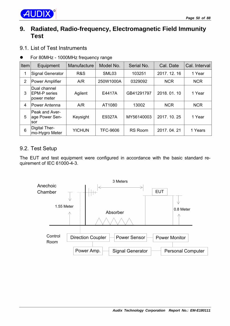
9. Radiated, Radio-frequency, Electromagnetic Field Immunity Test
9.1. List of Test Instruments
For 80MHz - 1000MHz frequency range
Item Equipment Manufacture Model No. Serial No. Cal. Date Cal. Interval
1 Signal Generator R&S SML03 103251 2017. 12. 16 1 Year
2 Power Amplifier A/R 250W1000A 0329092 NCR NCR
3 Dual channel EPM-P series power meter
Agilent E4417A GB41291797 2018. 01. 10 1 Year
4 Power Antenna A/R AT1080 13002 NCR NCR
5 Peak and Aver-age Power Sen-sor
Keysight E9327A MY56140003 2017. 10. 25 1 Year
6 Digital Ther-mo-Hygro Meter YICHUN TFC-9606 RS Room 2017. 04. 21 1 Years
9.2. Test Setup
The EUT and test equipment were configured in accordance with the basic standard re-quirement of IEC 61000-4-3.
0.8 Meter1.55 Meter
Anechoic Chamber
Control Room
EUT
3 Meters
Absorber
Direction Coupler
Signal Generator Personal ComputerPower Amp.
Power Sensor Power Monitor

Page 51 of 88
Audix Technology Corporation Report No.: EM-E180111
9.3. Applicable Standard and Test Specification
Immunity requirement is in accordance with EN 62040-2 clause 7.3.3 Test specification is in accordance with EN 62040-2 Table 6, Category C2 and C3 Basic standard is in accordance with IEC 61000-4-3
Test Specification (Test Level) Performance Criteria
Frequency Range 80-1000MHz
A Field Strength 10V/m
Modulation & Signal 80%, 1kHz AM
Deviation from applicable standard No deviation
9.4. Measurement Procedure
The measurement procedure specified in IEC 61000-4-3 clause 8 was used.
Setup the EUTs and associated equipment described as clause 4.1.
The EUT was placed on a non-conductive table 0.8 meter above the ground, the EUT and its simulators on the turn table and keep them 3 meters away from the transmitting antenna which is mounted on an antenna tower and fixes at 1.55 meter height.
The test was performed with the EUT exposed to both horizontally and vertically pola-rized fields on each of the four sides.
All the scanning conditions are as follows: Field Strength: 10 V/m (r.m.s, Unmodulated) Scanning Frequency: 80-1000MHz Amplitude Modulated: AM 1kHz, 80% Step Size: 1% increments The Rate of Sweep: 0.0015 decade/s Dwell Time: 3 sec. Test Position Angle: 0°, 90°, 180° and 270° Polarity of Antenna: H: Horizontal, V: Vertical
Page 52 of 88
Audix Technology Corporation Report No.: EM-E180111
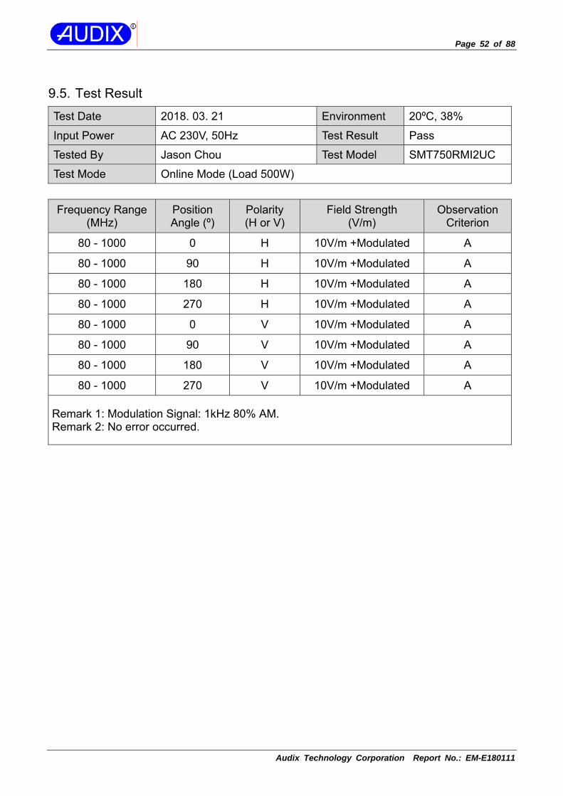
9.5. Test Result
Test Date 2018. 03. 21 Environment 20ºC, 38%
Input Power AC 230V, 50Hz Test Result Pass
Tested By Jason Chou Test Model SMT750RMI2UC
Test Mode Online Mode (Load 500W)
Frequency Range (MHz)
Position Angle (º)
Polarity (H or V)
Field Strength (V/m)
Observation Criterion
80 - 1000 0 H 10V/m +Modulated A
80 - 1000 90 H 10V/m +Modulated A
80 - 1000 180 H 10V/m +Modulated A
80 - 1000 270 H 10V/m +Modulated A
80 - 1000 0 V 10V/m +Modulated A
80 - 1000 90 V 10V/m +Modulated A
80 - 1000 180 V 10V/m +Modulated A
80 - 1000 270 V 10V/m +Modulated A
Remark 1: Modulation Signal: 1kHz 80% AM. Remark 2: No error occurred.

Page 53 of 88
Audix Technology Corporation Report No.: EM-E180111
10. Electrical fast transient/burst Immunity Test
10.1.List of Test Instruments
Item Equipment Manufacture Model No. Serial No. Cal. Date Cal. Interval
1 EMS Immunity Test System TESEQ NSG 3060 1519 2017. 07. 21 1 Year
2 C.D.N. TESEQ CDN 3063 2074 2017. 07. 21 1 Year
3 Burst/EFT Data-line Coupling Clamp
TESEQ CDN 3425 1717 2017. 07. 21 1 Year
4 Digital Ther-mo-Hygro Meter iMax HTC-1 No.2
EFT/SURGE 2017. 04. 21 1 Years
10.2.Test Setup
The EUT and test equipment were configured in accordance with the basic standard re-quirement of IEC 61000-4-4.
To AC Power Supply Network
AC Line
EMS Im-munity Test System
Grounding Plate Ground Plane
Signal Line
Insulation Support 0.1m CouplingClamp
EUT
C.D.N.

Page 54 of 88
Audix Technology Corporation Report No.: EM-E180111
10.3.Applicable Standard and Test Specification
Immunity requirement is in accordance with EN 62040-2 clause 7.3.3 Test specification is in accordance with EN 62040-2 Table 6, Category C2 and C3 Basic standard is in accordance with IEC 61000-4-4
Test Specification (Test Level) Performance Criteria
Signal and control ports : ±2kV AC input and output power ports : ±2kV
B Tr/Th : 5/50ns
Repetition frequency : 5kHz
Deviation from applicable standard No deviation
10.4.Measurement Procedure
The measurement procedure specified in IEC 61000-4-4 clause 8 was used.
Setup the EUTs and associated equipment described as clause 4.1.
The EUT and its simulators was placed 0.1m high above the ground reference plane which was a min. 1m*1m metallic sheet with 0.65mm minimum thickness.
This reference ground plane is project beyond the EUT by at least 0.1m on all sides and the minimum distance between EUT and all other conductive structure, except the ground plane beneath the EUT, shall be more than 0.5m.
For input and output AC power ports The EUT was connected to the power mains by using a coupling device which couples the EFT interference signal to AC power lines, and the length of the power line between the coupling device and the EUT shall be 0.5m or less. Both polarities of the test vol-tage should be applied during compliance test and the duration of the test can‘t less than 1min.
For signal lines and control lines ports The I/O interface cable of the EUT is connected to its simulator through a capacitive coupling clamp that is 1 meter long. The capacitive coupling clamp is impressed with burst noise for 1min and indirectly couples burst to I/O interface cable. [Remark: Applicable only to cables which according to the manufacturer’s specifica-tion supports communication on cable lengths greater than 3 m.]
For DC input and DC output power ports The DC power cable of the EUT is connected to the DC power source by using a coupling device which couples the EFT interference signal to DC power lines. Both po-larities of the test voltage should be applied during compliance test and the duration of the test can‘t less than 2min [Remark: Applicable only to DC power ports when the EUT supports this ports.]

Page 55 of 88
Audix Technology Corporation Report No.: EM-E180111
10.5.Test Result
Test Date 2018. 03. 22 Environment 23ºC, 49%
Input Power AC 230V, 50Hz Test Result Pass
Tested By Rex Wang Test Model SMT750RMI2UC
Test Mode Online Mode (Load 500W)
Input AC Power Port
Inject Line Polarity (+/-)
Test Voltage Peak (kV)
Inject Time(s) Inject Method Observation
Criterion L + 0.5, 1, 2 60 Direct A
L - 0.5, 1, 2 60 Direct A
N + 0.5, 1, 2 60 Direct A
N - 0.5, 1, 2 60 Direct A
PE + 0.5, 1, 2 60 Direct A
PE - 0.5, 1, 2 60 Direct A
L, N, PE + 0.5, 1, 2 60 Direct A
L, N, PE - 0.5, 1, 2 60 Direct A
I/O Interface Cable LAN + 0.5, 1, 2 60 Clamp A
LAN - 0.5, 1, 2 60 Clamp A
USB + 0.5, 1, 2 60 Clamp A
USB - 0.5, 1, 2 60 Clamp A
Universal I/O + 0.5, 1, 2 60 Clamp A
Universal I/O - 0.5, 1, 2 60 Clamp A
AC Out + 0.5, 1, 2 60 Clamp A
AC Out - 0.5, 1, 2 60 Clamp A
Remark: No error occurred.

Page 56 of 88
Audix Technology Corporation Report No.: EM-E180111
11. Surge Immunity Test
11.1.List of Test Instruments
For AC Input and Output Power Port
Item Equipment Manufacture Model No. Serial No. Cal. Date Cal. Interval
1 EMS Immunity Test System TESEQ NSG 3060 1519 2017. 07. 21 1 Year
2 CDN TESEQ CDN 3063 2074 2017. 07. 21 1 Year
3 Digital Ther-mo-Hygro Meter iMax HTC-1 No.2
EFT/SURGE 2017. 04. 21 1 Years
For Signal and Control Ports
Item Equipment Manufacture Model No. Serial No. Cal. Date Cal. Interval
1 EMS Immunity Test System TESEQ NSG 3060 1535 2017. 07. 21 1 Year
2 C.D.N. TESEQ INA 180 32516 NCR NCR
3 C.D.N. TESEQ INA 180 32519 NCR NCR
4 C.D.N. TESEQ CDN 118 33884 NCR NCR
5 C.D.N. TESEQ CDN 118 34745 NCR NCR
11.2.Test Setup
The EUT and test equipment were configured in accordance with the basic standard re-quirement of IEC 61000-4-5.
For AC Input and Output Power Port
For Signal and Control Ports
To AC Power Supply Network
AC Line
EMS Immunity Test System
Grounding Plate Ground Plane
CDN
Insulation Support 0.1m
EUT
C.D.N.
Signal or Control LineTo AC Power Supply Network
AC Line EMS Immunity Test System
Grounding PlateGround Plane
Insulation Support 0.1m
EUT
Page 57 of 88
Audix Technology Corporation Report No.: EM-E180111
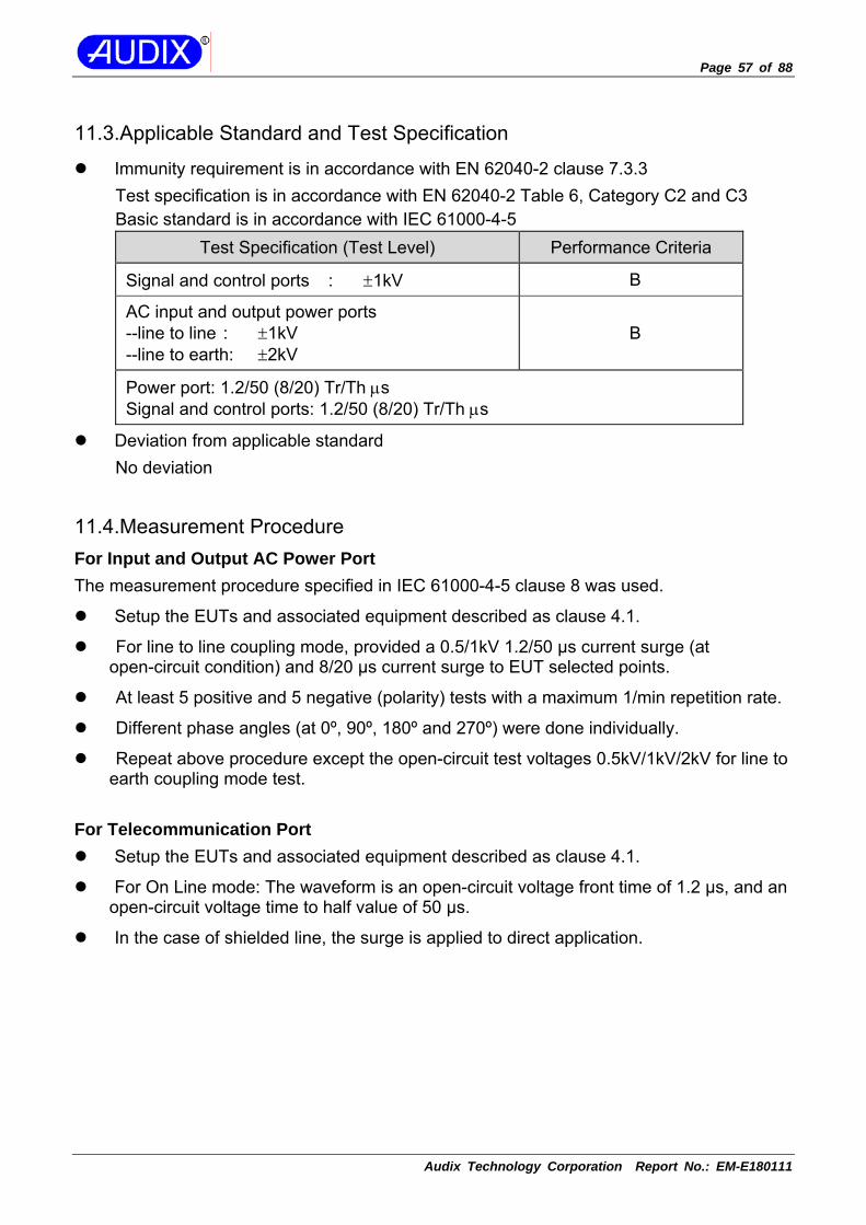
11.3.Applicable Standard and Test Specification
Immunity requirement is in accordance with EN 62040-2 clause 7.3.3 Test specification is in accordance with EN 62040-2 Table 6, Category C2 and C3 Basic standard is in accordance with IEC 61000-4-5
Test Specification (Test Level) Performance Criteria
Signal and control ports : ±1kV B
AC input and output power ports --line to line : ±1kV --line to earth: ±2kV
B
Power port: 1.2/50 (8/20) Tr/Th μs Signal and control ports: 1.2/50 (8/20) Tr/Th μs
Deviation from applicable standard No deviation
11.4.Measurement Procedure For Input and Output AC Power Port The measurement procedure specified in IEC 61000-4-5 clause 8 was used.
Setup the EUTs and associated equipment described as clause 4.1.
For line to line coupling mode, provided a 0.5/1kV 1.2/50 μs current surge (at open-circuit condition) and 8/20 μs current surge to EUT selected points.
At least 5 positive and 5 negative (polarity) tests with a maximum 1/min repetition rate.
Different phase angles (at 0º, 90º, 180º and 270º) were done individually.
Repeat above procedure except the open-circuit test voltages 0.5kV/1kV/2kV for line to earth coupling mode test.
For Telecommunication Port
Setup the EUTs and associated equipment described as clause 4.1.
For On Line mode: The waveform is an open-circuit voltage front time of 1.2 µs, and an open-circuit voltage time to half value of 50 µs.
In the case of shielded line, the surge is applied to direct application.

Page 58 of 88
Audix Technology Corporation Report No.: EM-E180111
11.5.Test Result
Test Date 2018. 03. 22 Environment 23ºC, 49%
Input Power AC 230V, 50Hz Test Result Pass
Tested By Rex Wang Test Model SMT750RMI2UC
Test Mode Online Mode (Load 500W)
Input AC Power Port, Open Circuit Voltage
Location Polarity (+/-)
Phase Angle (º)
Test Voltage Peak (kV)
No of Pulse
Observation Criterion
L-N
+ 0 0.5, 1 5 A + 90 0.5, 1 5 A + 180 0.5, 1 5 A + 270 0.5, 1 5 A - 0 0.5, 1 5 A - 90 0.5, 1 5 A - 180 0.5, 1 5 A - 270 0.5, 1 5 A
L-PE
+ 0 0.5, 1, 2 5 A + 90 0.5, 1, 2 5 A + 180 0.5, 1, 2 5 A + 270 0.5, 1, 2 5 A - 0 0.5, 1, 2 5 A - 90 0.5, 1, 2 5 A - 180 0.5, 1, 2 5 A - 270 0.5, 1, 2 5 A
N-PE
+ 0 0.5, 1, 2 5 A + 90 0.5, 1, 2 5 A + 180 0.5, 1, 2 5 A + 270 0.5, 1, 2 5 A - 0 0.5, 1, 2 5 A - 90 0.5, 1, 2 5 A - 180 0.5, 1, 2 5 A - 270 0.5, 1, 2 5 A
Remark: No error occurred.

Page 59 of 88
Audix Technology Corporation Report No.: EM-E180111
Test Date 2018. 03. 22 Environment 23ºC, 49%
Input Power AC 230V, 50Hz Test Result Pass
Tested By Rex Wang Test Model SMT750RMI2UC
Test Mode Online Mode (Load 500W)
Telecommunication Port
Location Polarity (+/-) Line Test Voltage
Peak (kV) No of Pulse
Observation Criterion
RJ45-LAN
+ Line to Line Mode
0.5, 1 5 A - 0.5, 1 5 A + Line to
Earth Mode0.5, 1 5 A
- 0.5, 1 5 A
Remark: No error occurred. waveform: 1.2/50 (8/20) Tr/Th μs. (On Line Test)

Page 60 of 88
Audix Technology Corporation Report No.: EM-E180111
12. Immunity to Conducted Disturbances, Induced by Ra-dio-Frequency Field Immunity Test
12.1.List of Test Instruments
Item Equipment Manufacture Model No. Serial No. Cal. Date Cal. Interval
1 Signal Genera-tor R&S SMC100A 101402 2017. 05. 06 1 Year
2 Power Amplifier A/R 100A250A 0330351 N.C.R. N.C.R.
3 Attenuator Weinschel 40-6-34 NB538 2017. 04. 24 1 Year
4 CDN Fischer FCC-801-M3-25A 9961 2018. 03. 07 1 Year
5 Digital Ther-mo-Hygrometer TEST 608-H1 30128573 2017. 03. 31 1 Year
12.2.Test Setup
The EUT and test equipment were configured in accordance with the basic standard re-quirement of IEC 61000-4-6.
Common Mode Test Setup
0.1m
EUT CDN AC Source
Ground Reference support
AttenuatorPower AmplifierSignal Generator
Personal Computer Control System

Page 61 of 88
Audix Technology Corporation Report No.: EM-E180111
EM Clamp Mode Test Setup
12.3.Applicable Standard and Test Specification
Immunity requirement is in accordance with EN 62040-2 clause 7.3.3 Test specification is in accordance with EN 62040-2 Table 6, Category C2 and C3 Basic standard is in accordance with IEC 61000-4-6
Test Specification (Test Level) Performance Criteria
Signal and control ports, AC input and output power ports
Frequency Range 0.15-80MHz
A Field Strength 10V (unmodulated, r.m.s)
Modulation 80% AM (1kHz)
Deviation from applicable standard No deviation
EUT CDN
Signal Generator Power Amplifier
50Ω
EM Injection Clamp
AE CDN
50Ω
0.1m 0.1m
0.1m < L <0.3m
DCN
RF Current Probe
Personal Computer Control System
Ground Reference support
Power Meter

Page 62 of 88
Audix Technology Corporation Report No.: EM-E180111
12.4.Measurement Procedure
The measurement procedure specified in IEC 61000-4-6 clause 8 was used. ** For AC Input and Output Power Line **
Setup the EUTs and associated equipment described as clause 4.1.
The EUT and supporting equipment were placed on an insulating support 0.1m high above a ground reference plane. CDN (coupling and decoupling device) was placed on the ground plane making contact with it at about 0.1-0.3m from EUT. Cables be-tween CDN and EUT were as short as possible.
The disturbance signal described below was injected to EUT through CDN.
The EUT operates within its operational mode(s) under intended climatic conditions af-ter power on.
The frequency range was swept from 0.15 to 80MHz using 10V signal level, and with the disturbance signal 80% amplitude modulated with a 1kHz sine wave.
The rate of sweep shall not exceed 1.5*10^3decades/s. Where the frequency was swept incrementally, the step size shall not exceed 1% of the start and thereafter 1% of the preceding frequency value.
Recording the EUT operating situation during compliance testing and decide the EUT immunity criterion.
** For Signal and Control Ports **
The EUT and supporting equipment were placed on an insulating support 0.1m high above a ground reference plane. EM Injection Clamp (coupling and decoupling device) was placed on the ground plane making contact with it at about 0.1-0.3m from EUT. Cables between EM Injection Clamp and EUT were as short as possible.
The CDN was placed on between AE and EUT. The EUT and AE of power through CDN, CDN terminated with 50Ω at the RF disturbance input port.
The disturbance signal described below was injected to EUT through EM Injection Clamp.

Page 63 of 88
Audix Technology Corporation Report No.: EM-E180111
12.5.Test Result
Test Date 2018. 03. 22 Environment 22ºC, 52%
Input Power AC 230V, 50Hz Test Result Pass
Tested By Sam Yan Test Model SMT750RMI2UC
Test Mode Online Mode (Load 500W)
Frequency Range (MHz) Injected Position Voltage Level Observation Cri-
terion
0.15 - 80MHz Main (Input AC Power Line) 10V(rms) + Modulated A
0.15 - 80MHz
I/O (LAN Cable, USB Cable,
Universal I/O Cable, AC Out Cable)
10V(rms) + Modulated A
Remark 1: Modulation Signal: 1kHz 80% AM. Remark 2: No error occurred.

Page 64 of 88
Audix Technology Corporation Report No.: EM-E180111
13. Power Frequency Magnetic Field Immunity Test
13.1.List of Test Instruments
Item Equipment Manufacture Model No. Serial No. Cal. Date Cal. Interval
1 Magnetic Field Generator
Narda S.T.S. / PMM PMM1008 0100X30101 2017. 11. 18 1 Year
2 Digital Ther-mo-Hygro Meter iMax HTC-1 No.2 Magnetic
Room 2017. 04. 21 1 Years
13.2.Test Setup
The EUT and test equipment were configured in accordance with the basic standard re-quirement of IEC 61000-4-8.
13.3.Applicable Standard and Test Specification
Immunity requirement is in accordance with EN 62040-2 clause 7.5 Test specification is in accordance with EN 62040-2 clause 7.5, Category C2 and C3 Basic standard is in accordance with IEC 61000-4-8
Test Specification (Test Level) Performance Criteria
Power Frequency 50Hz or 60Hz B
Magnetic Field Strength 30A/m (rms)
Deviation from applicable standard No deviation
EUT
Magnetic Field Generator
Induction Coil
Non-Conductive Table

Page 65 of 88
Audix Technology Corporation Report No.: EM-E180111
13.4.Measurement Procedure
The measurement procedure specified in IEC 61000-4-8 clause 8 was used.
Setup the EUTs and associated equipment described as clause 4.1.
The equipment cabinets which can be earthed shall be connected to the safety earth directly on the GRP or via the earth terminal to PE.
The EUT was placed on 0.8m high table, and subjected to the test magnetic field by using the induction coil of standard dimensions (1m x 2.6m).
The induction coil rotated by 90 degrees in order to expose the EUT to the test field with different orientations (at X-axis, Y-axis and X-axis).
The power supply, input and output circuits shall be connected to the sources of power supply, control and signal.
All cables of EUT exposed to magnetic field for 1m of their length.
The preferential range of test levels, respectively for continuous of the magnetic field, applicable to distribution networks at 50 Hz or 60 Hz.

Page 66 of 88
Audix Technology Corporation Report No.: EM-E180111
13.5.Test Result
Test Date 2018. 03. 22 Environment 22ºC, 48%
Input Power AC 230V, 50Hz Test Result Pass
Tested By Jacky Chen Test Model SMT750RMI2UC
Test Mode Online Mode (Load 500W)
Power Frequency Magnetic Field Strength Coil Orientation Testing
Duration Observation
Criterion
50Hz 30A/m X-axis 1 Min A
50Hz 30A/m Y-axis 1 Min A
50Hz 30A/m Z-axis 1 Min A
Remark: No error occurred.

Page 67 of 88
Audix Technology Corporation Report No.: EM-E180111
14. Low Frequency Signals Immunity Test
14.1.List of Test Instruments
Item Equipment Manufacture Model No. Serial No. Cal. Date Cal. Interval
1 Programmable Power Source TESEQ NSG1007-45 1248A04038 2017. 11. 28 2 Years
2 Isolation Trans-former N/A N/A N/A N/A N/A
3 Digital Ther-mo-Hygro Meter iMax HTC-1 No.2 Harmon-
ics Room 2017. 04. 21 1 Years
14.2.Test Setup
The EUT and test equipment were configured in accordance with the basic standard re-quirement of IEC 61000-2-2.
80cm
To AC Power Supply Network
AC Line
EUT Program-
mable Power Source
Ground Plane
TABLE
Isolation Transfor-
mer

Page 68 of 88
Audix Technology Corporation Report No.: EM-E180111
14.3.Applicable Standard and Test Specification
Immunity requirement is in accordance with EN 62040-2 clause 7.4 Test specification is in accordance with EN 62040-2 Annex D.6.1.1 and D.6.1.2 Basic standard is in accordance with IEC 61000-2-2
Test Specification (Test Level) Performance Criteria
Single-phase equipment
The test as a minimum shall be performed with a single sinusoidal disturbing voltage of 10 V, at a frequency which is slowly varied from 140 Hz to 360 Hz. Use can be made of a series injection cir-cuit where the mains supplies 50/60Hz power and the amplifier delivers only the harmonics. A
Three-phase equipment
The test set-up and voltage level for each phase is identical to the set-up for single-phase equipment; however, a three-phase variable frequency gene-rator is used (static or rotating). The frequency is slowly varied from 140 Hz to 360 Hz.
14.4.Measurement Procedure
The measurement procedure specified in IEC 61000-2-2 was used.
Setup the EUTs and associated equipment described as clause 4.1 and 14.2.
Let U.P.S. to be under charging and line status.
Adjust programmable AC source to output a 10Vrms (sine wave from 140 to 360Hz) that can be induced 10Vrms to link between AC source and U.P.S. (through the isolation transformer).
The induced signals shall mixed in normal AC source and U.P.S. shall withstand it and no performances shall be reduced.

Page 69 of 88
Audix Technology Corporation Report No.: EM-E180111
14.5.Test Result
Test Date 2018. 03. 22 Environment 22ºC, 49%
Input Power AC 230V, 50Hz Test Result Pass
Tested By Jacky chen Test Model SMT750RMI2UC
Test Mode Online Mode (Load 500W)
Frequency Range (MHz)
Strength Performance
Criterion
140
10V (rms) Sinusoidal
A 160 A 200 A 240 A 280 A 320 A 360 A
Isolation transformer Primary : Secondary = 1:1 Remark: No error occurred.
Page 70 of 88
Audix Technology Corporation Report No.: EM-E180111
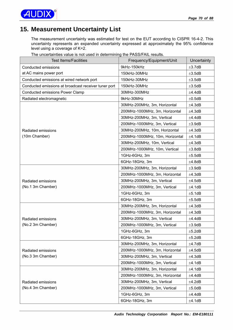
15. Measurement Uncertainty List The measurement uncertainty was estimated for test on the EUT according to CISPR 16-4-2. This uncertainty represents an expanded uncertainty expressed at approximately the 95% confidence level using a coverage of K=2. The uncertainties value is not used in determining the PASS/FAIL results.
Test Items/Facilities Frequency/Equipment/Unit Uncertainty
Conducted emissions at AC mains power port
9kHz-150kHz ±3.7dB 150kHz-30MHz ±3.5dB
Conducted emissions at wired network port 150kHz-30MHz ±3.5dB Conducted emissions at broadcast receiver tuner port 150kHz-30MHz ±3.5dB Conducted emissions Power Clamp 30MHz-300MHz ±4.4dB Radiated electromagnetic 9kHz-30MHz ±0.5dB
Radiated emissions (10m Chamber)
30MHz-200MHz, 3m, Horizontal ±4.3dB 200MHz-1000MHz, 3m, Horizontal ±4.3dB 30MHz-200MHz, 3m, Vertical ±4.4dB 200MHz-1000MHz, 3m, Vertical ±3.9dB 30MHz-200MHz, 10m, Horizontal ±4.3dB 200MHz-1000MHz, 10m, Horizontal ±4.1dB 30MHz-200MHz, 10m, Vertical ±4.3dB 200MHz-1000MHz, 10m, Vertical ±3.8dB 1GHz-6GHz, 3m ±5.5dB 6GHz-18GHz, 3m ±4.8dB
Radiated emissions (No.1 3m Chamber)
30MHz-200MHz, 3m, Horizontal ±3.9dB 200MHz-1000MHz, 3m, Horizontal ±4.3dB 30MHz-200MHz, 3m, Vertical ±4.5dB 200MHz-1000MHz, 3m, Vertical ±4.1dB 1GHz-6GHz, 3m ±5.1dB 6GHz-18GHz, 3m ±5.5dB
Radiated emissions (No.2 3m Chamber)
30MHz-200MHz, 3m, Horizontal ±4.3dB 200MHz-1000MHz, 3m, Horizontal ±4.3dB 30MHz-200MHz, 3m, Vertical ±4.4dB 200MHz-1000MHz, 3m, Vertical ±3.9dB 1GHz-6GHz, 3m ±5.2dB 6GHz-18GHz, 3m ±5.2dB
Radiated emissions (No.3 3m Chamber)
30MHz-200MHz, 3m, Horizontal ±4.7dB 200MHz-1000MHz, 3m, Horizontal ±4.5dB 30MHz-200MHz, 3m, Vertical ±4.3dB 200MHz-1000MHz, 3m, Vertical ±4.1dB
Radiated emissions (No.4 3m Chamber)
30MHz-200MHz, 3m, Horizontal ±4.1dB 200MHz-1000MHz, 3m, Horizontal ±4.4dB 30MHz-200MHz, 3m, Vertical ±4.2dB 200MHz-1000MHz, 3m, Vertical ±5.0dB 1GHz-6GHz, 3m ±4.4dB 6GHz-18GHz, 3m ±4.1dB

Page 71 of 88
Audix Technology Corporation Report No.: EM-E180111
Test Items/Facilities Frequency/Equipment/Unit Uncertainty
Radiated emissions (No.3 OATS)
30MHz-200MHz, 3m, Horizontal ±4.5dB 200MHz-1000MHz, 3m, Horizontal ±4.4dB 30MHz-200MHz, 3m, Vertical ±4.4dB 200MHz-1000MHz, 3m, Vertical ±4.0dB 30MHz-200MHz, 10m, Horizontal ±4.5dB 200MHz-1000MHz, 10m, Horizontal ±4.2dB 30MHz-200MHz, 10m, Vertical ±4.3dB 200MHz-1000MHz, 10m, Vertical ±4.0dB
Radiated emissions (No.5 OATS)
30MHz-200MHz, 3m, Horizontal ±4.2dB 200MHz-1000MHz, 3m, Horizontal ±4.7dB 30MHz-200MHz, 3m, Vertical ±4.4dB 200MHz-1000MHz, 3m, Vertical ±4.4dB 30MHz-200MHz, 10m, Horizontal ±4.2dB 200MHz-1000MHz, 10m, Horizontal ±4.6dB 30MHz-200MHz, 10m, Vertical ±4.4dB 200MHz-1000MHz, 10m, Vertical ±4.4dB
Radiated emissions (No.6 OATS)
30MHz-200MHz, 3m, Horizontal ±4.3dB 200MHz-1000MHz, 3m, Horizontal ±4.4dB 30MHz-200MHz, 3m, Vertical ±4.5dB 200MHz-1000MHz, 3m, Vertical ±4.1dB 30MHz-200MHz, 10m, Horizontal ±4.3dB 200MHz-1000MHz, 10m, Horizontal ±4.2dB 30MHz-200MHz, 10m, Vertical ±4.4dB 200MHz-1000MHz, 10m, Vertical ±4.1dB
Radiated emissions (No.7 OATS)
30MHz-200MHz, 3m, Horizontal ±3.9dB 200MHz-1000MHz, 3m, Horizontal ±4.5dB 30MHz-200MHz, 3m, Vertical ±4.6dB 200MHz-1000MHz, 3m, Vertical ±4.5dB 30MHz-200MHz, 10m, Horizontal ±3.9dB 200MHz-1000MHz, 10m, Horizontal ±4.3dB 30MHz-200MHz, 10m, Vertical ±4.6dB 200MHz-1000MHz, 10m, Vertical ±4.5dB
Radiated emissions (No.8 OATS)
30MHz-200MHz, 3m, Horizontal ±4.5dB 200MHz-1000MHz, 3m, Horizontal ±4.3dB 30MHz-200MHz, 3m, Vertical ±4.6dB 200MHz-1000MHz, 3m, Vertical ±4.1dB 30MHz-200MHz, 10m, Horizontal ±4.7dB 200MHz-1000MHz, 10m, Horizontal ±4.2dB 30MHz-200MHz, 10m, Vertical ±4.6dB 200MHz-1000MHz, 10m, Vertical ±4.0dB

Page 72 of 88
Audix Technology Corporation Report No.: EM-E180111
Test Items/Facilities Frequency/Equipment/Unit Uncertainty
Harmonic current NSG 1007-45 ±0.7% Voltage fluctuations & flicker NSG 1007-45 ±0.2%
Electrostatic discharge (ESD)
NSG 437 Ucurrent= 7.3% Uvoltage= 1.0% Utime = 9.0%
Ditto Ucurrent = 4.0% Uvoltage = 2.0% Utime = 3.0%
MZ-15/EC Ucurrent = 10.0% Uvoltage = 1.8% Utime = 20.0%
Radio-frequency electromagnetic field, Continuous radiated disturbances (RS)
80MHz-200MHz ±1.7dB 200MHz-1000MHz ±1.8dB 1GHz-6GHz ±1.7dB
Electrical fast transient/burst (EFT)
AC power port Uvoltage = 1.0% Utime = 4.0%
Signal port Uvoltage = 4.0% Utime = 3.0%
Surge
Open-circuit output voltage 0.5kV-6kV (1.2us/50us) Uvoltage = 4.0%
Open-circuit output voltage 0.5kV-6kV (10us/700us) Uvoltage = 4.0%
Rise time (30%-90%) x 1.67: 0.5kV-6kV (1.2us/50us)
Utime = 3.0%
Rise time (30%-90%) x 1.67: 0.5kV-6kV (10us/700us)
Utime = 3.0%
Duration time: 0.5kV-6kV (1.2us/50us) Utime = 3.0%
Duration time: 0.5kV-6kV (10us/700us) Utime = 3.0% Short-circuit output current 0.25KA-3KA (8us / 20us) Ucurrent = 3.0%
Rise time (10%-90%) x 1.25: (8us/20us) Utime = 3.0%
Duration time: (8us/20us) Utime = 3.0% Radio-frequency, continuous conducted disturbances (CS)
CDN (AC power port) 1.5 dB
EM-Clamp (Signal port) 3.3 dB
Power-frequency magnetic field (PFMF)
MAG100.1 4% PMM1008 2%
Voltage dips TESEQ Uvoltage = 0.1% Ucurrent = 0.2%

Page 73 of 88
Audix Technology Corporation Report No.: EM-E180111
16. Photographs 16.1.Conducted Emissions Measurement
For AC Mains Power Port
Front View of Conducted Measurement
Back View of Conducted Measurement

Page 74 of 88
Audix Technology Corporation Report No.: EM-E180111
16.2.Radiated Emissions Measurement
For Frequency Range 30 – 1000MHz
Front View of Radiated Measurement
Back View of Radiated Measurement

Page 75 of 88
Audix Technology Corporation Report No.: EM-E180111
16.3.Input Current Harmonics Measurement

Page 76 of 88
Audix Technology Corporation Report No.: EM-E180111
16.4.Electrostatic Discharge Immunity Test
Air & Contact Discharge
HCP & VCP

Page 77 of 88
Audix Technology Corporation Report No.: EM-E180111
ESD Test Points
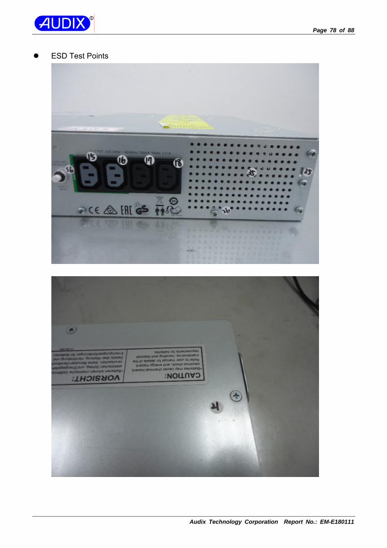
Page 78 of 88
Audix Technology Corporation Report No.: EM-E180111
ESD Test Points

Page 79 of 88
Audix Technology Corporation Report No.: EM-E180111
ESD Test Points

Page 80 of 88
Audix Technology Corporation Report No.: EM-E180111
ESD Test Points

Page 81 of 88
Audix Technology Corporation Report No.: EM-E180111
ESD Test Points

Page 82 of 88
Audix Technology Corporation Report No.: EM-E180111
ESD Test Points

Page 83 of 88
Audix Technology Corporation Report No.: EM-E180111
16.5.Radiated, Radio-Frequency, Electromagnetic Field Immunity Test

Page 84 of 88
Audix Technology Corporation Report No.: EM-E180111
16.6.Electrical Fast Transient/Burst Immunity Test
Injection Position: AC Power Line
Injection Position: I/O Cable

Page 85 of 88
Audix Technology Corporation Report No.: EM-E180111
16.7.Surge Immunity Test
For AC Input and Output Power Ports
For Signal and Control Ports
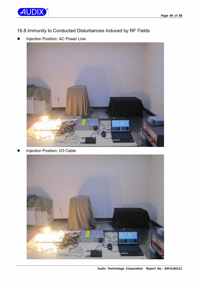
Page 86 of 88
Audix Technology Corporation Report No.: EM-E180111
16.8.Immunity to Conducted Disturbances Induced by RF Fields
Injection Position: AC Power Line
Injection Position: I/O Cable

Page 87 of 88
Audix Technology Corporation Report No.: EM-E180111
16.9.Power Frequency Magnetic Field Immunity Test
16.10.Low Frequency Signals Immunity Test

Page 88 of 88
Audix Technology Corporation Report No.: EM-E180111
16.11.Partner System

APPENDIX I
Audix Technology Corporation Report No.: EM-E180111
APPENDIX I
(Photos of EUT)

APPENDIX I - Page 1 of 5
Audix Technology Corporation Report No.: EM-E180111
For model: SMT750RMI2UC, Figure 1 ~ 6 Figure 1
General Appearance (Front & Side View)
Figure 2 General Appearance (Back & Side View)

APPENDIX I - Page 2 of 5
Audix Technology Corporation Report No.: EM-E180111
Figure 3
Appearance (I/O View)
Figure 4 Appearance (I/O View)

APPENDIX I - Page 3 of 5
Audix Technology Corporation Report No.: EM-E180111
Figure 5
Internal View (Remove Cover)
Figure 6 Internal View

APPENDIX I - Page 4 of 5
Audix Technology Corporation Report No.: EM-E180111
For model: SMT750IC, Figure 7 ~ 10 Figure 7
General Appearance (Front & Side View)
Figure 8 General Appearance (Back & Side View)

APPENDIX I - Page 5 of 5
Audix Technology Corporation Report No.: EM-E180111
Figure 9
Appearance (I/O View)
Figure 10 Internal View (Remove Cover)

APPENDIX II
Audix Technology Corporation Report No.: EM-E180111
APPENDIX II
(Data Pretest)

APPENDIX II - Page 1 of 20
Audix Technology Corporation Report No.: EM-E180111
Conducted emissionsat AC mains power port

APPENDIX II - Page 2 of 20
Audix Technology Corporation Report No.: EM-E180111

APPENDIX II - Page 3 of 20
Audix Technology Corporation Report No.: EM-E180111

APPENDIX II - Page 4 of 20
Audix Technology Corporation Report No.: EM-E180111

APPENDIX II - Page 5 of 20
Audix Technology Corporation Report No.: EM-E180111
DC 24V

APPENDIX II - Page 6 of 20
Audix Technology Corporation Report No.: EM-E180111
DC 24V

APPENDIX II - Page 7 of 20
Audix Technology Corporation Report No.: EM-E180111
Conducted emissionsat signal and telecommunication ports

APPENDIX II - Page 8 of 20
Audix Technology Corporation Report No.: EM-E180111

APPENDIX II - Page 9 of 20
Audix Technology Corporation Report No.: EM-E180111

APPENDIX II - Page 10 of 20
Audix Technology Corporation Report No.: EM-E180111

APPENDIX II - Page 11 of 20
Audix Technology Corporation Report No.: EM-E180111

APPENDIX II - Page 12 of 20
Audix Technology Corporation Report No.: EM-E180111

APPENDIX II - Page 13 of 20
Audix Technology Corporation Report No.: EM-E180111
Radiated emissions (30 – 1000MHz)

APPENDIX II - Page 14 of 20
Audix Technology Corporation Report No.: EM-E180111
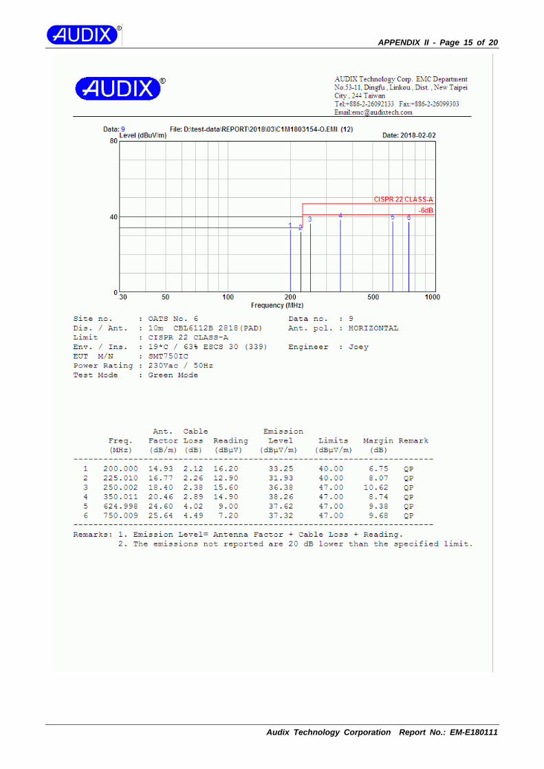
APPENDIX II - Page 15 of 20
Audix Technology Corporation Report No.: EM-E180111

APPENDIX II - Page 16 of 20
Audix Technology Corporation Report No.: EM-E180111

APPENDIX II - Page 17 of 20
Audix Technology Corporation Report No.: EM-E180111
DC 24V

APPENDIX II - Page 18 of 20
Audix Technology Corporation Report No.: EM-E180111
DC 24V

APPENDIX II - Page 19 of 20
Audix Technology Corporation Report No.: EM-E180111

APPENDIX II - Page 20 of 20
Audix Technology Corporation Report No.: EM-E180111