technical construction file (tcf)
TRANSCRIPT

TECHNICAL CONSTRUCTION FILE
(TCF) FILE NO IECHO-2020A01
DATE 25.05.2020
PRODUCT NAME: Digital Cutting Machine
MODEL: BK, BK2, BK3, BKL, BKM, BKMS, GLK, LCP, SC, SCT, TK, TK3S, GLS,
LCPS, PK, VK, TK4S, SK2
ACCORDING TO:
MACHINERY DIRECTIVE: 2006/42/EC LOW VOLTAGE DIRECTIVE: 2014/35/EU
ELECTROMAGNETIC COMPATIBILITY DIRECTIVE 2014/30/EU
Hangzhou IECHO Science &Technology Co., Ltd No.1 Building, NO.1 Weiye Road, Binjiang District, Hangzhou city,
Zhejiang Province, China.

Content Part I General
1. 1.1 General description 2. 1.2 Product Parameter 3. 1.3 Quality control system 4. 1.4 List of applicable regulations and standards Part II Assessment of conformity 1. 2.1 Essential health and safety requirements 2. 2.2 Risk assessment Part III Test report 1. 3.1 EN 12044 test report 2. 3.2 BS EN 60204-1 test report 3. 3.3 EN61000-6-3 & EN61000-6-1 Annex Technical Information 1. A.1 Declaration of conformity 2. A.2 Nameplate 3. A.3 Main parts list 4. A.4 Electrical circuit diagram 5. A.5 Original Instructions

1.1 General description
Basically, this kind of machine belongs to simple machine and with low risk when using it. All possible risk have been analysis in the risk assessment report and been prevent by suitable ways. In order to ensure the conformity for CE marking for these machines, some main European and/or International standards have been used to made assessment of conformity, they are EN 12044:2005+A1:2009. FOOTWEAR, LEATHER AND IMITATION LEATHER GOODS MANUFACTURING MACHINES. CUTTING AND PUNCHING MACHINES. SAFETY REQUIREMENTS. EN 60204-1:2018 SAFETY OF MACHINERY- ELECTRICAL EQUIPMENT OF MACHINES - PART 1: GENERAL REQUIREMENTS BS EN IEC 61000-6-1:2019 EN 61000-6-1:2019. ELECTROMAGNETIC COMPATIBILITY (EMC). GENERIC STANDARDS. IMMUNITY STANDARD FOR RESIDENTIAL, COMMERCIAL AND LIGHT-INDUSTRIAL ENVIRONMENTS EN 61000-6-3:2007+A1:2011. ELECTROMAGNETIC COMPATIBILITY (EMC). GENERIC STANDARDS. EMISSION STANDARD FOR RESIDENTIAL, COMMERCIAL AND LIGHT-INDUSTRIAL ENVIRONMENTS The test reports for these applicable standards in detail have been included in the relevant sub-clauses of this technical construction file.

1.2 Product Parameter
MODEL BK SC
Max. cutting speed(mm/s) 1000 800
Cutting accuracy(mm) 0.02 0.03
Max. Cutting thickness(mm) 50 50
Data format DXF HPGL
Cutting width(MAX mm) 800mm-3000mm
Cutting length(MAX mm) 800mm-3000mm
Interface Network
Driver Servo motor
Media absorption Vacuum
Power 380V/50HZ
Operation environment Temperature 0 -40 Humidity 20%-70%RH

1.3 Quality control system In order to ensure the conformity of the series production, the HANGZHOU IECHO SCIENCE &TECHNOLOGY CO., LTD has taken the related procedures mentioned below
1 Carry out the inspection for parts and components according to the TCF
Before the assemblies of the series production, the QC engineers of HANGZHOU IECHO SCIENCE &TECHNOLOGY CO., LTD has to check and inspect the technical specifications and intended functions of parts and components to ensure the correct use of them according to the contents of TCF and principle described in the related technical information.
2 Carry out the inspection testing for the products before packing
Before packing the products, the QC engineers of HANGZHOU IECHO SCIENCE &TECHNOLOGY CO., LTD have to do the necessary inspection and testing to ensure the conformity of related requirements, in particularly, the testing and inspection of outer feature.
3 Carry out the inspection for the packing
After finishing the necessary inspection and testing for the products, an inspection for the packing has to be done to ensure the necessary elements being included in this packing before shipment.
4 Provision for the change of design
Any change of the products described in this TCF must be checked in detail and written down again in the TCF by the designer of HANGZHOU IECHO SCIENCE &TECHNOLOGY CO., LTD if the change may effects the related electrical or mechanical characteristics.
5 Provision for the Quality Assurance
For the provisions of internal control measures to ensure the conformity of series production of the machines, HANGZHOU IECHO SCIENCE &TECHNOLOGY CO., LTD has built an internal quality control system in accordance with the international standard of ISO 9001.

1.5 List of applicable regulations and standards Directive:
Machinery Safety directive: 2006/42/EC Low voltage directive: 2014/35/EU Electromagnetic Compatibility Directive 2014/30/Eu
Standards: EN 12044:2005+A1:2009. FOOTWEAR, LEATHER AND IMITATION LEATHER GOODS MANUFACTURING MACHINES. CUTTING AND PUNCHING MACHINES. SAFETY REQUIREMENTS. EN 60204-1:2018 SAFETY OF MACHINERY- ELECTRICAL EQUIPMENT OF MACHINES - PART 1: GENERAL REQUIREMENTS BS EN IEC 61000-6-1:2019 EN 61000-6-1:2019. ELECTROMAGNETIC COMPATIBILITY (EMC). GENERIC STANDARDS. IMMUNITY STANDARD FOR RESIDENTIAL, COMMERCIAL AND LIGHT-INDUSTRIAL ENVIRONMENTS EN 61000-6-3:2007+A1:2011. ELECTROMAGNETIC COMPATIBILITY (EMC). GENERIC STANDARDS. EMISSION STANDARD FOR RESIDENTIAL, COMMERCIAL AND LIGHT-INDUSTRIAL ENVIRONMENTS

Part II Assessment of conformity

2.1 Essential health and safety requirements relating to the design and construction of machinery
1. Essential health and safety requirements - P 1.1 General remarks - P 1.1.1 Definitions - P 1.1.2 Principles of safety integration - P (a) Machinery must be designed and constructed so
that it is fitted for its function, and can be operated, adjusted and maintained without putting persons at risk when these operations are carried out under the conditions foreseen but also taking into account any reasonably foreseeable misuse thereof. The aim of measures taken must be to eliminate any risk throughout the foreseeable lifetime of the machinery including the phases of transport, assembly, dismantling, disabling and scrapping.
These requirements have been taken into account during the design of this machine.
P
(b) In selecting the most appropriate methods, the manufacturer or his authorised representative must apply the following principles, in the order given:
- These requirements have been taken into account during the design of this machine.
P
eliminate or reduce risks as far as possible(inherently safe machinery design and construction)
take the necessary protection measure in relation to risks that cannot be eliminated
— inform users of the residual risks due to any shortcomings of the protective measures adopted, indicate whether any particular training is required and specify any need to provide personal protective equipment.
P
(c) When designing and constructing machinery and when drafting the instructions, the manufacturer or his authorised representative must envisage not only the intended use of the machinery but also any reasonably foreseeable misuse thereof. The machinery must be designed and constructed in such a way as to prevent abnormal use if such use would engender a risk. Where appropriate, the instructions must draw the user's attention to ways — which experience has shown might occur — in which the machinery should not be used.
These requirements have been taken into account during the design of this machine.
P
(d) Machinery must be designed and constructed to take account of the constraints to which the operator is subject as a result of the necessary or foreseeable use of personal protective equipment.
These requirements have been taken into account during the design of this machine.
P
(e) Machinery must be supplied with all the special equipment and accessories essential to enable it to be adjusted, maintained and used safely.
P
1.1.3 Materials and products - The materials used to construct machinery or
products used or created during its use must not endanger persons' safety or health. In particular, where fluids are used, machinery must be designed and constructed to prevent risks due to filling, use, recovery or draining.
P
1.1.4 Lighting - N.A

Machinery must be supplied with integral lighting suitable for the operations concerned where the absence thereof is likely to cause a risk despite ambient lighting of normal intensity. Machinery must be designed and constructed so that there is no area of shadow likely to cause nuisance, that there is no irritating dazzle and that there are no dangerous stroboscopic effects on moving parts due to the lighting. Internal parts requiring frequent inspection and adjustment, and maintenance areas must be provided with appropriate lighting.
1.1.5 Design of machinery to facilitate its handling - P Machinery or each component part thereof must: - P - be capable of being handle and transported safely Enough measures have been
taken to ensure the safe of the handling.
P
- be packaged or designed so that it can be stored safely and without damage
P
During the transportation of the machinery and/or its component parts, there must be no possibility of sudden movements or of hazards due to instability as long as the machinery and/or its component parts are handled in accordance with the instructions.
N.A
Where the weight, size or shape of machinery or its various component parts prevents them from being moved by hand, the machinery or each components part must: - either be fitted with attachments for lifting gear, or - be designed so that it can be fitted with such
attachments, or - be shaped in such a way that standard lifting gear can easily be attached
N.A
Where machinery or one of its component parts is to be moved by hand, it must: - either be easily movable, or - be equipped for picking up and moving safely. Special arrangements must be made for the handling of tools and/or machinery parts which, even if lightweight, could be hazardous.
P
1.1.6 Ergonomics - P Under the intended conditions of use, the discomfort,
fatigue and physical and psychological stress faced by the operator must be reduced to the minimum possible, taking into account ergonomic principles such as:
allowing for the variability of the operator's physical dimensions, strength and stamina,
providing enough space for movements of the parts of the operator's body,
avoiding a machine-determined work rate, avoiding monitoring that requires lengthy
concentration, adapting the man/machinery interface to the
foreseeable characteristics of the operators.
P
1.1.7 Operating positions - N.A The operating position must be designed and
constructed in such a way as to avoid any risk due to N.A

exhaust gases and/or lack of oxygen. If the machinery is intended to be used in a hazardous environment presenting risks to the health and safety of the operator or if the machinery itself gives rise to a hazardous environment, adequate means must be provided to ensure that the operator has good working conditions and is protected against any foreseeable hazards. Where appropriate, the operating position must be fitted with an adequate cabin designed, constructed and/or equipped to fulfil the above requirements. The exit must allow rapid evacuation. Moreover, when applicable, an emergency exit must be provided in a direction which is different from the usual exit.
1.1.8 Seating N.A Where appropriate and where the working conditions
so permit, work stations constituting an integral part of the machinery must be designed for the installation of seats. If the operator is intended to sit during operation and the operating position is an integral part of the machinery, the seat must be provided with the machinery. The operator's seat must enable him to maintain a stable position. Furthermore, the seat and its distance from the control devices must be capable of being adapted to the operator. If the machinery is subject to vibrations, the seat must be designed and constructed in such a way as to reduce the vibrations transmitted to the operator to the lowest level that is reasonably possible. The seat mountings must withstand all stresses to which they can be subjected. Where there is no floor beneath the feet of the operator, footrests covered with a slip-resistant material must be provided.
N.A
1.2 CONTROL SYSTEMS - P 1.2.1 Safety and reliability of control systems - P Control systems must be designed and constructed in
such a way as to prevent hazardous situations from arising. Above all, they must be designed and constructed in such a way that:
The control system for this machine is safe
P
— they can withstand the intended operating stresses and external influences, — a fault in the hardware or the software of the control system does not lead to hazardous situations, — errors in the control system logic do not lead to hazardous situations, — reasonably foreseeable human error during operation does not lead to hazardous situations.
The control system can withstand related effects during normal operation.
P
Particular attention must be given to the following points:
P
— the machinery must not start unexpectedly, — the parameters of the machinery must not change in an uncontrolled way, where such change may lead to hazardous situations, — the machinery must not be prevented from stopping if the stop command has already been given, — no moving part of the machinery or piece held by
P

the machinery must fall or be ejected, — automatic or manual stopping of the moving parts, whatever they may be, must be unimpeded, — the protective devices must remain fully effective or give a stop command, — the safety-related parts of the control system must apply in a coherent way to the whole of an assembly of machinery and/or partly completed machinery.
For cable-less control, an automatic stop must be activated when correct control signals are not received, including loss of communication.
P
1.2.2 Control devices - P Control devices must be: - P — clearly visible and identifiable, using pictograms
where appropriate, — positioned in such a way as to be safely operated without hesitation or loss of time and without ambiguity, — designed in such a way that the movement of the control device is consistent with its effect, — located outside the danger zones, except where necessary for certain control devices such as an emergency stop or a teach pendant, — positioned in such a way that their operation cannot cause additional risk, — designed or protected in such a way that the desired effect, where a hazard is involved, can only be achieved by a deliberate action, — made in such a way as to withstand foreseeable forces; particular attention must be paid to emergency stop devices liable to be subjected to considerable forces.
Visible markings are provided. Good design meets the requirements.
P
Where a control device is designed and constructed to perform several different actions, namely where there is no one-to-one correspondence, the action to be performed must be clearly displayed and subject to confirmation, where necessary. Control devices must be so arranged that their layout, travel and resistance to operation are compatible with the action to be performed, taking account of ergonomic principles. Machinery must be fitted with indicators as required for safe operation. The operator must be able to read them from the control position. From each control position, the operator must be able to ensure that no-one is in the danger zones, or the control system must be designed and constructed in such a way that starting is prevented while someone is in the danger zone. If neither of these possibilities is applicable, before the machinery starts, an acoustic and/or visual warning signal must be given. The exposed persons must have time to leave the danger zone or prevent the machinery starting up. If necessary, means must be provided to ensure that the machinery can be controlled only from control positions located in one or more predetermined zones or locations. Where there is more than one control position, the control system must be designed in such a way that
P

the use of one of them precludes the use of the others, except for stop controls and emergency stops. When machinery has two or more operating positions, each position must be provided with all the required control devices without the operators hindering or putting each other into a hazardous situation.
1.2.3 Starting - It must be possible to start machinery only by
voluntary actuation of a control provided for the purpose.
Devices preventing unintended starting have been provided.
P
The same requirement applies: - P - when restarting the machinery after stoppage,
whatever the cause - when effecting a significant change in the operating
conditions
P
However, the restarting of the machinery or a change in operating conditions may be effected by voluntary actuation of a device other than the control device provided for the purpose, on condition that this does not lead to a hazardous situation. For machinery functioning in automatic mode, the starting of the machinery, restarting after a stoppage, or a change in operating conditions may be possible without intervention, provided this does not lead to a hazardous situation. Where machinery has several starting control devices and the operators can therefore put each other in danger, additional devices must be fitted to rule out such risks. If safety requires that starting and/or stopping must be performed in a specific sequence, there must be devices which ensure that these operations are performed in the correct order.
Reset is necessary before restarting.
P
1.2.4 Stopping - P 1.2.4.1. Normal stopping - P Machinery must be fitted with a control device
whereby the machinery can be brought safely to a complete stop.
A normal stop control has been provided.
P
Each workstation must be fitted with a control to stop some or all of the moving parts of the machinery, depending on the existing hazard, so that the machinery is rendered safe
A normal stop control has been provided.
P
The machinery’s stop control must have priority over the start controls
It has priority over the start control.
P
Once the machinery or its dangerous parts have stopped, the energy supply to the actuators concerned must be cut off
P
1.2.4.2 Operational stop - P Where, for operational reasons, a stop control that
does not cut off the energy supply to the actuators is required, the stop condition must be monitored and maintained.
P
1.2.4.3 Emergency stop - P Machinery must be fitted with one or more emergency
stop devices to enable actual or impending danger to be averted.
P
The following exceptions apply: N.A

machinery in which an emergency stop device would not lessen the risk, either because it would not reduce the stopping time or because it would not enable the special measures required to deal with the risk to be taken,
portable hand-held and/or hand-guided machinery. The device must: have clearly identifiable, clearly visible and quickly
accessible control devices,
stop the hazardous process as quickly as possible, without creating additional risks,
where necessary, trigger or permit the triggering of certain safeguard movements.
Once active operation of the emergency stop device has ceased following a stop command, that command must be sustained by engagement of the emergency stop device until that engagement is specifically overridden; it must not be possible to engage the device without triggering a stop command; it must be possible to disengage the device only by an appropriate operation, and disengaging the device must not restart the machinery but only permit restarting. The emergency stop function must be available and operational at all times, regardless of the operating mode. Emergency stop devices must be a back-up to other safeguarding measures and not a substitute for them.
1.2.4.4 Assembly of machinery P In the case of machinery or parts of machinery
designed to work together, the machinery must be designed and constructed in such a way that the stop controls, including the emergency stop devices, can stop not only the machinery itself but also all related equipment, if its continued operation may be dangerous.
P
1.2.5 Selection of control or operating modes - P The control or operating mode selected must override
all other control or operating modes, with the exception of the emergency stop. If machinery has been designed and constructed to allow its use in several control or operating modes requiring different protective measures and/or work procedures, it must be fitted with a mode selector which can be locked in each position. Each position of the selector must be clearly identifiable and must correspond to a single operating or control mode. The selector may be replaced by another selection method which restricts the use of certain functions of the machinery to certain categories of operator. If, for certain operations, the machinery must be able to operate with a guard displaced or removed and/or a protective device disabled, the control or operating mode selector must simultaneously: — disable all other control or operating modes, — permit operation of hazardous functions only by control devices requiring sustained action, — permit the operation of hazardous functions only in
P

reduced risk conditions while preventing hazards from linked sequences, —prevent any operation of hazardous functions by voluntary or involuntary action on the machine's sensor. If these four conditions cannot be fulfilled simultaneously, the control or operating mode selector must activate other protective measures designed and constructed to ensure a safe intervention zone. In addition, the operator must be able to control operation of the parts he is working on from the adjustment point.
1.2.6 Failure of the power supply - The interruption, re-establishment after an
interruption or fluctuation in whatever manner of the power supply to the machinery must not lead to a dangerous situation
No any dangerous situation has been found.
P
Particular attention must be given to the following points:
-
- the machinery must not start unexpectedly P - the parameters of the machinery must not change in
an uncontrolled way when such change can lead to hazardous situations,
All the parameters stay the same. P
- the machinery must not be prevented from stopping if the command has already been given,
P
-no moving part of the machinery or piece held by the machinery must fall or be ejected,
No such hazards. P
-automatic or manual stopping of the moving parts, whatever they may be, must be unimpeded,
P
— the protective devices must remain fully effective or give a stop command.
P
1.3 PROTECTION AGAINST MECHANICAL HAZARDS P 1.3.1 Risk of loss of Stability - P Machinery and its components and fittings must be
stable enough to avoid overturning, falling or uncontrolled movements during transportation, assembly, dismantling and any other action involving the machinery. If the shape of the machinery itself or its intended installation does not offer sufficient stability, appropriate means of anchorage must be incorporated and indicated in the instructions.
These requirements have been taken into account design. The whole equipment is stable enough.
P
1.3.2 Risk of break-up during operation - P The various parts of machinery and their linkages
must be able to withstand the stress to which they are subject when used
All parts of the machine can withstand related stress when they are used.
P
The durability of the materials used must be adequate for the nature of the workplace foreseen by the manufacturer, in particular as regards the phenomena of fatigue, aging, corrosion and abrasion
All materials used for this machine are appropriate for their intended use and have adequate life.
P
The instructions must indicate the type and frequency of inspections and maintenance required for safety reasons. They must, where appropriate, indicate the parts subject to wear and the criteria for replacement.
P
Where a risk of rupture or disintegration remains despite the measures taken, the parts concerned must be mounted, positioned and/or guarded in such a way that any fragments will be contained,
P

preventing hazardous situations. Both rigid and flexible pipes carrying fluids,
particularly those under high pressure, must be able to withstand the foreseen internal and external stresses and must be firmly attached and/or protected to ensure that no risk is posed by a rupture.
N.A
Where the material to be processed is fed to the tool automatically, the following conditions must be fulfilled to avoid risks to persons:
- N/A
- when the work piece comes into contact with the tool, the later must have attained its normal working conditions
N.A
- when the tool starts and/or stops(intentionally or accidentally) the feed movement and the tool movement must be coordinated
. N.A
1.3.3 Risked due to falling or ejected objects - P Precautions must be taken to prevent risks from
falling or ejected object The fuel will not be ejected. P
1.3.4 Risks due to surfaces, edges or angles - P Insofar as their purpose allows, accessible parts of
the machinery must have no sharp edges, no sharp angles, and no rough surfaces likely to cause injury
P
1.3.5 Risks related to combined machinery - P Where the machinery is intended to carry out several
different operations with manual removal of the piece between each operation (combined machinery), it must be designed and constructed in such a way as to enable each element to be used separately without the other elements constituting a risk for exposed persons.
P
For this purpose, it must be possible to start and stop separately and elements that are not protected
N.A
1.3.6 Risks relating to variations in operating conditions - P Where the machinery performs operations under
different conditions of use, it must be designed and constructed in such a way that selection and adjustment of these conditions can be carried out safely and reliably.
P
1.3.7 Risks related to moving parts - The moving parts of machinery must be designed and
constructed in such a way as to prevent risks of contact which could lead to accidents or must, where risks persist, be fitted with guards or protective devices. All necessary steps must be taken to prevent accidental blockage of moving parts involved in the work. In cases where, despite the precautions taken, a blockage is likely to occur, the necessary specific protective devices and tools must, when appropriate, be provided to enable the equipment to be safely unblocked. The instructions and, where possible, a sign on the machinery shall identify these specific protective devices and how they are to be used.
P
1.3.8 Choice of protection against risk related to moving parts
N.A

Guards or protection devices used to protect against the risks related to moving parts must be selected on the basis of the type of risk The following guidelines must be used to help make the choice
N.A
1.3.8.1 Moving transmission parts - N.A Guards designed to protect exposed persons against
the risks associated with moving transmission parts must be
- N.A
— either fixed guards as referred to in section 1.4.2.1, or
N.A
— interlocking movable guards as referred to in section 1.4.2.2. Interlocking movable guards should be used where frequent access is envisaged.
N.A
1.3.8.2 Moving parts involved in the process - N.A Guards or protective devices designed to protect
persons against the hazards generated by moving parts involved in the process must be: — either fixed guards as referred to in section 1.4.2.1, or — interlocking movable guards as referred to in section 1.4.2.2, or — protective devices as referred to in section 1.4.3, or — a combination of the above. However, when certain moving parts directly involved in the process cannot be made completely inaccessible during operation owing to operations requiring operator intervention, such parts must be fitted with: — fixed guards or interlocking movable guards preventing access to those sections of the parts that are not used in the work, and — adjustable guards as referred to in section 1.4.2.3 restricting access to those sections of the moving parts where access is necessary.
N.A
1.3.9 Risks of uncontrolled movements - N.A When a part of the machinery has been stopped, any
drift away from the stopping position, for whatever reason other than action on the control devices, must be prevented or must be such that it does not present a hazard.
1.4 Required characteristics of guards and protection devices
- N.A
1.4.1 General requirement - N.A Guards and protection devices must: - N.A -be of robust construction
-be securely held in place, -not give rise to any additional hazard, -not be easy to by-pass or render non-operational, - be located at an adequate distance from the danger zone, -cause minimum obstruction to the view of the production process, and -enable essential work to be carried out on the installation and/or replacement of tools and for maintenance
N.A

purposes by restricting access exclusively to the area where the work has to be done, if possible without the guard having to be removed or the protective device having to be disabled. In addition, guards must, where possible, protect against the ejection or falling of materials or objects and against emissions generated by the machinery.
1.4.2 Special requirements for guards - N.A 1.4.2.1 Fixed guards - N.A Fixed guards must be fixed by systems that can be
opened or removed only with tools. Their fixing systems must remain attached to the guards or to the machinery when the guards are removed. Where possible, guards must be incapable of remaining in place without their fixings.
N.A
1.4.2.2 Interlocking movable guards N.A. Interlocking movable guards must:
as far as possible remain attached to the machinery when open,
be designed and constructed in such a way that they can be adjusted only by means of an intentional action. Interlocking movable guards must be associated with an interlocking device that:
prevents the start of hazardous machinery functions until they are closed and
gives a stop command whenever they are no longer closed. Where it is possible for an operator to reach the danger zone before the risk due to the hazardous machinery functions has ceased, movable guards must be associated with a guard locking device in addition to an interlocking device that:
prevents the start of hazardous machinery functions until the guard is closed and locked, and
keeps the guard closed and locked until the risk of injury from the hazardous machinery functions has ceased. Interlocking movable guards must be designed in such a way that the absence or failure of one of their components prevents starting or stops the hazardous machinery functions.
1.4.2.3 Adjustable guards restricting access N.A Adjustable guards restricting access to those areas of
the moving parts strictly necessary for the work must be:
adjustable manually or automatically, depending on the type of work involved, and
readily adjustable without the use of tools.
1.4.3 Special requirements for protection devices - N.A Protective devices must be designed and
incorporated into the control system in such a way that:
- N.A
Protective devices must be designed and incorporated into the control system in such a way that: moving parts cannot start up while they are within
N.A

the operator's reach, persons cannot reach moving parts while the parts
are moving, and the absence or failure of one of their components
prevents starting or stops the moving parts. Protective devices must be adjustable only by means
of an intentional action. 1.5 Risk due to other hazards - P 1.5.1 Electricity supply - P Where machinery has an electricity supply it must be
designed, constructed and equipped in a way that all hazards of an electrical nature are or can be prevented
The safety objectives set out in Directive 73/23/EEC shall apply to machinery. However, the obligations Concerning conformity assessment and the placing on the market and/or putting into service of machinery with regard to electrical hazards are governed solely by this Directive.
N.A
1.5.2 Static electricity - P Machinery must be designed and constructed to
prevent or limit the build-up of potentially dangerous electrostatic charges and/or be fitted with a discharging system.
P
1.5.3 Energy supply other than electricity - N.A Where machinery is powered by source of energy
other than electricity, it must be so designed, constructed and equipped as to avoid all potential risks associated with such sources of energy.
N.A
1.5.4 Error of fitting - N.A Errors likely to be made when fitting or refitting certain
parts which could be a source of risk must be made impossible by the design and construction of such parts or, failing this, by information given on the parts themselves and/or their housings. The same information must be given on moving parts and/or their housings where the direction of movement needs to be known in order to avoid a risk.
N.A
Where necessary, the instructions must give further information on these risks.
N.A
Where a faulty connection can be the source of risk, incorrect connections must be made impossible by Design or, failing this, by information given on the elements to be connected and, where appropriate, on the means of connection.
N.A
1.5.5 Extreme temperatures - N.A Steps must be taken to eliminate any risk of injury
arising from contact with or proximity to machinery parts or materials at high or very low temperatures. The necessary steps must also be taken to avoid or protect against the risk of hot or very cold material being ejected.
N.A
1.5.6 Fire - N.A Machinery must be designed and constructed in such
a way as to avoid any risk of fire or overheating posed by the machinery itself or by gases, liquids, dust, vapours or other substances produced or used by the machinery.
N.A
1.5.7 Explosion - N.A
Machinery must be designed and constructed in such a way as to avoid any risk of explosion posed by the machinery itself or by gases, liquids, dust, vapours or other substances produced or used by the machinery. Machinery must comply, as far as the risk of explosion due to its use in a potentially explosive atmosphere is concerned, with the provisions of the specific Community Directives.
N.A
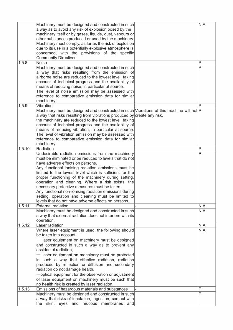
1.5.8 Noise - P Machinery must be designed and constructed in such
a way that risks resulting from the emission of airborne noise are reduced to the lowest level, taking account of technical progress and the availability of means of reducing noise, in particular at source. The level of noise emission may be assessed with reference to comparative emission data for similar machinery.
P
1.5.9 Vibration - P Machinery must be designed and constructed in such
a way that risks resulting from vibrations produced by the machinery are reduced to the lowest level, taking account of technical progress and the availability of means of reducing vibration, in particular at source. The level of vibration emission may be assessed with reference to comparative emission data for similar machinery.
Vibrations of this machine will not create any risk.
P
1.5.10 Radiation - P Undesirable radiation emissions from the machinery
must be eliminated or be reduced to levels that do not have adverse effects on persons. Any functional ionising radiation emissions must be limited to the lowest level which is sufficient for the proper functioning of the machinery during setting, operation and cleaning. Where a risk exists, the necessary protective measures must be taken. Any functional non-ionising radiation emissions during setting, operation and cleaning must be limited to levels that do not have adverse effects on persons.
P
1.5.11 External radiation - N.A Machinery must be designed and constructed in such
a way that external radiation does not interfere with its operation.
N.A
1.5.12 Laser radiation N.A Where laser equipment is used, the following should
be taken into account: laser equipment on machinery must be designed
and constructed in such a way as to prevent any accidental radiation,
laser equipment on machinery must be protected in such a way that effective radiation, radiation produced by reflection or diffusion and secondary radiation do not damage health,
optical equipment for the observation or adjustment of laser equipment on machinery must be such that no health risk is created by laser radiation.
N.A
1.5.13 Emissions of hazardous materials and substances - P Machinery must be designed and constructed in such
a way that risks of inhalation, ingestion, contact with the skin, eyes and mucous membranes and
P

penetration through the skin of hazardous materials and substances which it produces can be avoided. Where a hazard cannot be eliminated, the machinery must be so equipped that hazardous materials and substances can be contained, evacuated, precipitated by water spraying, filtered or treated by another equally effective method. Where the process is not totally enclosed during normal operation of the machinery, the devices for containment and/or evacuation must be situated in such a way as to have the maximum effect.
1.5.14 Risk of being trapped in a machine Machinery must be designed, constructed or fitted with a means of preventing a person from being enclosed within it or, if that is impossible, with a means of summoning help.
N.A
1.5.15 Risk of slipping, tripping or falling N.A Parts of the machinery where persons are liable to
move about or stand must be designed and constructed in such a way as to prevent persons slipping, tripping or falling on or off these parts. Where appropriate, these parts must be fitted with handholds that are fixed relative to the user and that enable them to maintain their stability.
N.A
1.5.16 Lightning N.A Machinery in need of protection against the effects of
lightning while being used must be fitted with a system for conducting the resultant electrical charge to earth.
N.A
1.6 Maintenance - P 1.6.1 Machinery maintenance - P Adjustment and maintenance points must be located
outside danger zones. It must be possible to carry out adjustment, maintenance, repair, cleaning and servicing operations while machinery is at a standstill. If one or more of the above conditions cannot be satisfied for technical reasons, measures must be taken to ensure that these operations can be carried out safely (see section 1.2.5). In the case of automated machinery and, where necessary, other machinery, a connecting device for mounting diagnostic fault-finding equipment must be provided. Automated machinery components which have to be changed frequently must be capable of being removed and replaced easily and safely. Access to the components must enable these tasks to be carried out with the necessary technical means in accordance with a specified operating method.
The design and construction of this machine are in conformity with this requirement.
P
1.6.2 Access to operating position and servicing points P Machinery must be designed and constructed in such
a way as to allow access in safety to all areas where intervention is necessary during operation, adjustment and maintenance of the machinery.
P
1.6.3 Isolation of energy sources - N.A Machinery must be fitted with means to isolate it from
all energy sources. Such isolators must be clearly identified. They must be capable of being locked if reconnection could endanger persons. Isolators must

also be capable of being locked where an operator is unable, from any of the points to which he has access, to check that the energy is still cut off. In the case of machinery capable of being plugged into an electricity supply, removal of the plug is sufficient, provided that the operator can check from any of the points to which he has access that the plug remains removed. After the energy is cut off, it must be possible to dissipate normally any energy remaining or stored in the circuits of the machinery without risk to persons. As an exception to the requirement laid down in the previous paragraphs, certain circuits may remain connected to their energy sources in order, for example, to hold parts, to protect information, to light interiors, etc. In this case, special steps must be taken to ensure operator safety.
1.6.4 Operator intervention - Machinery must be so designed, constructed and
equipped that the need for operator intervention is limited. If operator intervention cannot be avoided, it must be possible to carry it out easily and safely.
The design and construction of this machine are in conformity with these requirements.
P
1.6.5 Cleaning of internal parts - The machinery must be designed and constructed in
such a way that it is possible to clean internal parts which have contained dangerous substances or preparations without entering them; any necessary unblocking must also be possible from the outside. If it is impossible to avoid entering the machinery, it must be designed and constructed in such a way as to allow cleaning to take place safely.
P
1.7 Information - P 1.7.0 Information and warnings on the machinery - P Information and warnings on the machinery should
preferably be provided in the form of readily understandable symbols or pictograms. Any written or verbal information and warnings must be expressed in an official Community language or languages, which may be determined in accordance with the Treaty by the Member State in which the machinery is placed on the market and/or put into service and may be accompanied, on request, by versions in any other official Community language or languages understood by the operators.
The information is identified clearly and can be easily under understood.
P
1.7.1.1 Information and information devices P The information needed to control machinery must be
provided in a form that is unambiguous and easily understood. It must not be excessive to the extent of overloading the operator. Visual display units or any other interactive means of communication between the operator and the machine must be easily understood and easy to use.
P
1.7.1.2 Warning devices - Where the health and safety of persons may be
endangered by a fault in the operation of unsupervised machinery, the machinery must be equipped in such a way as to give an appropriate acoustic or light signal as a warning.
The warning devices comply with ergonomic principles.
P

Where machinery is equipped with warning devices these must be unambiguous and easily perceived. The operator must have facilities to check the operation of such warning devices at all times. The requirements of the specific Community Directives concerning colours and safety signals must be complied with.
1.7.2 Warning of residual risks - P Where risks remain despite the inherent safe design
measures, safeguarding and complementary protective measures adopted, the necessary warnings, including warning devices, must be provided.
P
1.7.3 Marking of machinery - P All machinery must be marked visibly, legibly and
indelibly with the following minimum particular - P
— the business name and full address of the manufacturer and, where applicable, his authorised representative, — designation of the machinery, — the CE Marking (see Annex III), — designation of series or type, — serial number, if any, — the year of construction, that is the year in which the manufacturing process is completed.
P
It is prohibited to pre-date or post-date the machinery when affixing the CE marking. Furthermore, machinery designed and constructed for use in a potentially explosive atmosphere must be marked accordingly. Machinery must also bear full information relevant to its type and essential for safe use. Such information is subject to the requirements set out in section 1.7.1. Where a machine part must be handled during use with lifting equipment, its mass must be indicated legibly, indelibly and unambiguously.
P
1.7.4 Instruction - P All machinery must be accompanied by instructions in
the official Community language or languages of the Member State in which it is placed on the market
and/or put into service. The instructions accompanying the machinery must be either ‘Original instructions’ or a ‘Translation of the original instructions’, in which case the translation must be accompanied by the original instructions. By way of exception, the maintenance instructions intended for use by specialised personnel mandated by the manufacturer or his authorised representative may be supplied in only one Community language which the specialised personnel understand. The instructions must be drafted in accordance with the principles set out below.
P
1.7.4.1 General principles for the drafting of instructions - P (a) The instructions must be drafted in one or more
official Community languages. The words ‘Original instructions’ must appear on the language version(s) verified by the manufacturer or his authorised representative. (b) Where no ‘Original instructions’ exist in the official
All related information have been provided within the instruction manual
P

language(s) of the country where the machinery is to be used, a translation into that/those language(s) must be provided by the manufacturer or his authorized representative or by the person bringing the machinery into the language area in question. The translations must bear the words ‘Translation of the original instructions’. (c) The contents of the instructions must cover not only the intended use of the machinery but also take into account any reasonably foreseeable misuse thereof. (d) In the case of machinery intended for use by
non-professional operators, the wording and layout of the instructions for use must take into account the level of general education and acumen that can reasonably be expected from such operators.
1.7.4.2 Contents of the instructions All related information has been provided within the instruction manual.
P
Each instruction manual must contain, where applicable, at least the following information: (a) the business name and full address of the manufacturer and of his authorized representative; (b) the designation of the machinery as marked on the machinery itself, except for the serial number (see section 1.7.3); (c) the EC declaration of conformity, or a document setting out the contents of the EC declaration of conformity, showing the particulars of the machinery, not necessarily including the serial number and the signature; (d) a general description of the machinery; (e) the drawings, diagrams, descriptions and explanations necessary for the use, maintenance and repair of the machinery and for checking its correct functioning; (f) a description of the workstation(s) likely to be occupied by operators; (g) a description of the intended use of the machinery; (h) warnings concerning ways in which the machinery must not be used that experience has shown might occur; (i) assembly, installation and connection instructions, including drawings, diagrams and the means of attachment and the designation of the chassis or installation on which the machinery is to be mounted; (j) instructions relating to installation and assembly for reducing noise or vibration; (k) instructions for the putting into service and use of the machinery and, if necessary, instructions for the training of operators; (l) information about the residual risks that remain despite the inherent safe design measures, safeguarding and complementary protective measures adopted; (m) instructions on the protective measures to be taken by the user, including, where appropriate, the personal protective equipment to be provided; (n) the essential characteristics of tools which may be fitted to the machinery;
All related information has been provided within the instruction manual.
P

(o) the conditions in which the machinery meets the requirement of stability during use, transportation, assembly, dismantling when out of service, testing or foreseeable breakdowns; (p) instructions with a view to ensuring that transport, handling and storage operations can be made safely, giving the mass of the machinery and of its various parts where these are regularly to be transported separately; (q) the operating method to be followed in the event of accident or breakdown; if a blockage is likely to occur, the operating method to be followed so as to enable the equipment to be safely unblocked; (r) the description of the adjustment and maintenance operations that should be carried out by the user and the preventive maintenance measures that should be observed; (s) instructions designed to enable adjustment and maintenance to be carried out safely, including the protective measures that should be taken during these operations; (t) the specifications of the spare parts to be used, when these affect the health and safety of operators; (u) the following information on airborne noise emissions:
the A-weighted emission sound pressure level at workstations, where this exceeds 70 dB(A); where this level does not exceed 70 dB(A), this fact must be indicated,
the peak C-weighted instantaneous sound pressure value at workstations, where this exceeds 63 Pa (130 dB in relation to 20 μPa),
the A-weighted sound power level emitted by the machinery, where the A-weighted emission sound pressure level at workstations exceeds 80 dB(A). These values must be either those actually measured for the machinery in question or those established on the basis of measurements taken for technically comparable machinery which is representative of the machinery to be produced. In the case of very large machinery, instead of the A-weighted sound power level, the A-weighted emission sound pressure levels at specified positions around the machinery may be indicated. Where the harmonized standards are not applied, sound levels must be measured using the most appropriate method for the machinery. Whenever sound emission values are indicated the uncertainties surrounding these values must be specified. The operating conditions of the machinery during measurement and the measuring methods used must be described. Where the workstation(s) are undefined or cannot be defined, A-weighted sound pressure levels must be measured at a distance of 1 metre from the surface of the machinery and at a height of 1,6 metres from the floor or access platform. The position and value of the maximum sound pressure must be indicated. Where specific Community Directives lay down other

requirements for the measurement of sound pressure levels or sound power levels, those Directives must be applied and the corresponding provisions of this section shall not apply; (v) where machinery is likely to emit non-ionising radiation which may cause harm to persons, in particular persons with active or non-active implantable medical devices, information concerning the radiation emitted for the operator and exposed persons.
1.7.4.3 Sales literature P Sales literature describing the machinery must not
contradict the instructions as regards health and safety aspects. Sales literature describing the performance characteristics of machinery must contain the same information on emissions as is contained in the instructions.
P
2 Supplementary essential health and safety requirements for certain categories of machinery
Not applicable. N.A
3 Supplementary essential health and safety requirements to offset hazards due to the mobility of machinery
N.A
4 Supplementary essential health and safety requirements to offset hazards due to lifting operations
Not applicable. N.A
5 Supplementary essential health and safety requirements for machinery intended for underground work
Not applicable. N.A
6 Supplementary essential health and safety requirements for machinery presenting particular hazards due to the lifting of persons
Not applicable. N.A

2.2
Ris
k as
sess
men
t
This
risk
ass
essm
ent r
epor
t is b
ased
on
the
met
hods
in th
e EN
ISO
1210
0 st
anda
rds,
and
the
4 fa
ctor
s S-A
-G-W
hav
e be
en u
sed
for e
valu
atin
g th
e le
vel
of ri
sks.
S
Seve
rity
of p
ossi
ble
harm
-S
1Sl
ight
norm
ally
reve
rsib
le-S
2Se
rious
norm
ally
irre
vers
ible
-S3
Cau
se a
few
men
die
-S
4C
alam
ity o
r cau
se m
any
men
die
AFr
eque
ncy
any
dura
tion
of e
xpos
ure
-A
1Se
ldom
to v
ery
ofte
n
-A2
Freq
uent
to c
ontin
uous
GPo
ssib
ilitie
s of a
void
ance
-G
1Po
ssib
le
-G2
Impo
ssib
le
WPr
obab
ility
of o
ccur
renc
e of
har
m
-W1
Low
-W
2M
ediu
m
-W3
Hig
h

Solu
tions
for t
he le
vel o
f haz
ards
1Pr
otec
ted
by w
arni
ng si
gn
2Pr
otec
ted
by g
uard
and
war
ning
sign
3
Con
side
r the
oth
er d
esig
n, c
hoos
e th
e be
st o
ne, a
dd b
oth
guar
d an
d w
arni
ng si
gn
4C
onsi
der a
noth
er tw
o de
sign
, cho
ose
the
best
one
, add
bot
h gu
ard
and
war
ning
sign
5
Con
side
r ano
ther
thre
e de
sign
, cho
ose
the
best
one
, add
bot
h gu
ard
and
war
ning
sign

No.
H
azar
ds so
urce
H
azar
ds o
ccur
ing
S
A
G
W
Lev
el
Con
trol
mea
ns
S A
G
W
L
evel
Har
zard
s, ha
zard
ous s
ituat
ions
and
haz
ardo
us e
vent
s
1 M
echa
nica
l haz
ards
/
/ /
/ /
/ /
/ /
/ /
/
1.0
Mec
hani
cal h
azar
ds d
ue to
mac
hine
par
ts
or w
ork
piec
es e
.g.:
a) sh
ape
b) re
lativ
e lo
catio
n c)
mas
s an
d st
abili
ty
(pot
entia
l ene
rgy
of e
lem
ents
whi
ch m
ay m
ove
unde
r th
e ef
fect
of g
ravi
ty
kine
tic e
nerg
y of
gra
vity
) d)
mas
s an
d ve
loci
ty (
kine
tic e
nerg
y of
gr
avity
) e)
inad
equa
cy o
f mec
hani
cal s
treng
th
wor
king
S2
A
1 G
2 W
2 2
1.D
esig
n 2.
Add
war
ning
sign
S1
A
1 G
1 W
1 1
Mec
hani
cal h
azar
ds d
ue to
acc
umul
atio
n of
ene
rgy
insi
de th
e m
achi
nery
e.g
. f)
ela
stic
ele
men
ts (s
prin
gs)
g)
liqui
ds
and
gase
s un
der
pr
essu
re
h) th
e ef
fect
of v
acuu
m
N/A
1.1
Cru
shin
g N
/A
1.
2 Sh
earin
g N
/A
1.
3 C
uttin
g or
seve
ring
N/A
1.4
Enta
ngle
men
t w
orki
ng
S2
A1
G1
W3
2 1.
Des
ign,
2.
Add
war
ning
sign
S1
A
1 G
1 W
1 1
1.5
Dra
win
g-in
or t
rapp
ing
N/A

No.
H
azar
ds so
urce
H
azar
ds o
ccur
ing
S
A
G
W
Lev
el
Con
trol
mea
ns
S A
G
W
L
evel
1.
6 Im
pact
N
/A
1.
7 St
abbi
ng o
r pun
ctur
e N
/A
1.
8 Fr
ictio
n or
abr
asio
n N
/A
1.9
Hig
h pr
essu
re fl
uid
inje
ctio
n or
eje
ctio
n N
/A
2 E
lect
rica
l haz
ards
/
/ /
/ /
/ /
/ /
/ /
/
2.1
Con
tact
of p
erso
ns w
ith li
ve p
arts
w
orki
ng
S2
A1
G1
W3
2 1.
Des
ign,
2.
Add
war
ning
sign
S1
A
1 G
1 W
1 1
2.2
Con
tact
with
par
ts w
hich
hav
e be
com
e liv
e un
der f
aulty
con
ditio
ns
wor
king
S2
A
1 G
1 W
3 2
1.D
esig
n,
2. A
dd w
arni
ng si
gn
S1
A1
G1
W1
1
2.3
App
roac
h to
live
par
t und
er h
igh
volta
ge
wor
king
S2
A
1 G
1 W
3 2
1.D
esig
n,
2. A
dd w
arni
ng si
gn
S1
A1
G1
W1
1
2.4
Elec
trost
atic
phe
nom
ena
N/A
2.5
Ther
mal
rad
iatio
n or
oth
er p
heno
men
a su
ch a
s pr
ojec
tion
of m
olte
n pa
rticl
es
and
chem
ical
ef
fect
s fr
om
shor
t-circ
uits
, ove
rload
s etc
.
wor
king
S2
A
1 G
1 W
3 2
1.D
esig
n,
2. A
dd w
arni
ng si
gn
S1
A1
G1
W1
1
3 T
herm
al h
azar
ds
/ /
/ /
/ /
/ /
/ /
/ /
3.1
Bur
ns ,
scal
ds a
nd o
ther
inj
urie
s by
a
poss
ible
con
tact
of
pers
ons
with
obj
ects
or
mat
eria
ls w
ith a
n ex
trem
e hi
gh o
r low
te
mpe
ratu
re, b
y fla
mes
or e
xplo
sion
s and
al
so b
y th
e ra
diat
ion
of h
eat s
ourc
es
wor
king
S2
A
1 G
1 W
3 2
1.D
esig
n,
2. A
dd w
arni
ng si
gn
S1
A1
G1
W1
1
3.2
Dam
age
to h
ealth
by
hot o
r col
d w
orki
ng
envi
ronm
ent
N/A

No.
H
azar
ds so
urce
H
azar
ds o
ccur
ing
S
A
G
W
Lev
el
Con
trol
mea
ns
S A
G
W
L
evel
4
Haz
ards
gen
erat
ed b
y no
ise
/
/ /
/ /
/ /
/ /
/ /
/
4.1
Hea
ring
loss
(d
eafn
ess)
, ot
her
phys
iolo
gica
l dis
orde
rs
wor
king
S2
A
1 G
1 W
3 2
1.D
esig
n,
2. A
dd w
arni
ng si
gn
S1
A1
G1
W1
1
4.2
Inte
rfer
ence
w
ith
spee
ch
com
mun
icat
ion,
aco
ustic
sign
als,
etc.
N
/A
5 H
azar
ds g
ener
ated
by
vibr
atio
n
/ /
/ /
/ /
/ /
/ /
/ /
5.1
Use
of h
and-
held
mac
hine
s re
sulti
ng in
a
varie
ty
of
neur
olog
ical
an
d va
scul
ar
diso
rder
N
/A
5.2
Who
le b
ody
vibr
atio
n, p
artic
ular
whe
n co
mbi
ned
with
po
or p
ostu
res
N/A
6 H
azar
ds
gene
rate
d b
y r
adia
tion
/
/ /
/ /
/ /
/ /
/ /
/
6.1
Low
fr
eque
ncy,
ra
dio
freq
uenc
y ra
diat
ion,
mic
row
aves
N
/A
6.2
Infr
ared
,
visi
ble
an
d
ultra
viol
et
light
N
/A
-
6.3
X a
nd g
amm
a ra
ys
N/A
6.4
Alp
ha, b
eta
rays
, ele
ctro
n or
ion
beam
s, ne
utro
ns
N/A
6.5
Lase
rs
N/A
7
Haz
ards
g
ener
ated
by
m
ater
ials
an
d
subs
tanc
es
pr
oces
sed
or
us
ed
by t
he m
achi
nery
/ /
/ /
/ /
/ /
/ /
/ /

No.
H
azar
ds so
urce
H
azar
ds o
ccur
ing
S
A
G
W
Lev
el
Con
trol
mea
ns
S A
G
W
L
evel
7.1
Haz
ards
fro
m c
onta
ct w
ith o
r in
hala
tion
of h
arm
ful
fluid
s, ga
ses,
mis
ts,
fum
es
and
dust
s N
/A
7.2
Fire
and
exp
losi
on h
azar
d N
/A
7.3
Bio
logi
cal a
nd m
icro
-bio
logi
cal (
vira
l or
bact
eria
l) ha
zard
s N
/A
8 H
azar
ds
gene
rate
d by
ne
glec
ting
ergo
nom
ic
prin
cipl
es
in
mac
hine
de
sign
as
/
/ /
/ /
/ /
/ /
/ /
/
8.1
Unh
ealth
y po
stur
es o
r exc
essiv
e ef
fort
N/A
8.2
Inad
equa
te c
onsi
dera
tion
of h
and-
arm
or
foot
-leg
anat
omy
N/A
8.3
Neg
lect
ed
use
of
pers
onal
pr
otec
tion
equi
pmen
t N
/A
8.4
Inad
equa
te lo
cal l
ight
ing
N/A
8.5
Men
tal o
verlo
ad o
r und
er lo
ad, s
tress
N/A
8.6
Hum
an e
rror
, hum
an b
ehav
ior
N
/A
8.7
Inad
equa
te
desi
gn,
loca
tion
or
iden
tific
atio
n of
man
ual c
ontro
ls
N/A
8.8
Inad
equa
te d
esig
n or
loca
tion
of
visu
al
disp
lay
units
N
/A
9 C
ombi
natio
n of
haz
ards
N
/A

No.
H
azar
ds so
urce
H
azar
ds o
ccur
ing
S
A
G
W
Lev
el
Con
trol
mea
ns
S A
G
W
L
evel
10
Une
xpec
ted
star
t-up
, un
expe
cted
ov
erru
n/ov
er-s
peed
(or
any
simila
r m
alfu
nctio
n) f
rom
:
/ /
/ /
/ /
/ /
/ /
/ /
10.1
Fa
ilure
/dis
orde
r of t
he c
ontro
l sys
tem
w
orki
ng
S2
A2
G1
W2
3 1.
Opt
imiz
e de
sign
S1
A
1 G
1 W
1 1
10.2
R
esto
ratio
n of
ene
rgy
supp
ly a
fter
an
inte
rrup
tion
N/A
10.3
Ex
tern
al
influ
ence
s on
el
ectri
cal
equi
pmen
t N
/A
10.4
O
ther
ext
erna
l inf
luen
ces
(gra
vity
, win
d,
etc.
) N
/A
10.5
Er
rors
in th
e so
ftwar
e N
/A
10.6
Er
rors
mad
e by
the
ope
rato
r (d
ue t
o m
ism
atch
of
m
achi
nery
w
ith
hum
an
char
acte
ristic
s and
abi
litie
s, se
e 8.
6)
N/A
11
Impo
ssib
ility
of
stop
ping
the
mac
hine
in
the
best
pos
sibl
e co
nditi
ons
N/A
12
Var
iatio
ns i
n th
e ro
tatio
nal
spee
d of
to
ols
N/A
13
Failu
re o
f the
pow
er su
pply
N
/A
14
Fa
ilure
of t
he c
ontr
ol c
ircu
it N
/A
15
E
rror
s of f
ittin
g N
/A
16
B
reak
-up
duri
ng o
pera
tion
N/A

No.
H
azar
ds so
urce
H
azar
ds o
ccur
ing
S
A
G
W
Lev
el
Con
trol
mea
ns
S A
G
W
L
evel
17
Falli
ng o
r ej
ecte
d ob
ject
s or
fluid
s N
/A
18
Los
s of
st
abili
ty
/ ov
ertu
rnin
g of
m
achi
nery
N
/A
19
Slip
, tr
ip a
nd f
all
of p
erso
ns (
rela
ted
to m
achi
nery
) N
/A
Add
ition
al h
azar
ds h
azar
dous
situ
atio
ns a
nd h
azar
ds e
vent
s due
to m
obili
ty
20
Rel
atin
g to
the
trav
ellin
g fu
nctio
n N
/A
21
Lin
ked
to th
e w
ork
posit
ion
(incl
udin
g dr
ivin
g st
atio
n) o
n th
e m
achi
ne
N/A
22
Due
to th
e co
ntro
l sys
tem
N
/A
24
Due
to
the
pow
er s
ourc
e an
d to
the
tr
ansm
issi
on o
f pow
er
N/A
25
From
/to th
ird
pers
ons
N/A
26
Insu
ffic
ient
in
stru
ctio
ns
for
the
driv
er/o
pera
tor
N/A
Add
ition
al h
azar
ds, h
azar
dous
situ
atio
ns a
nd h
azar
dous
eve
nts d
ue to
lift
ing
27
Mec
hani
cal
haza
rds
and
haza
rdou
s ev
ents
N
/A
28
From
ligh
tnin
g N
/A
29
Haz
ards
ge
nera
ted
by
negl
ectin
g er
gono
mic
pri
ncip
les
N/A
Add
ition
al h
azar
ds, h
azar
dous
situ
atio
ns a
nd h
azar
dous
eve
nts d
ue to
und
ergr
ound
wor
k

No.
H
azar
ds so
urce
H
azar
ds o
ccur
ing
S
A
G
W
Lev
el
Con
trol
mea
ns
S A
G
W
L
evel
30
Mec
hani
cal
haza
rds
and
haza
rdou
s ev
ents
due
to:
N/A
31
Res
tric
ted
mov
emen
t of p
erso
ns
N/A
32
Fire
and
exp
losio
n N
/A
33
E
mis
sion
of d
ust,
gase
s etc
. N
/A
1.
Add
ition
al h
azar
ds, h
azar
dous
situ
atio
ns a
nd h
azar
dous
eve
nts d
ue to
the
liftin
g or
mov
ing
of p
erso
ns
34
Mec
hani
cal
haza
rds
and
haza
rdou
s ev
ents
due
to:
N/A
35
Falli
ng o
f per
son
from
per
son
carr
ier
N/A
36
Falli
ng
or
over
turn
ing
of
pers
on
carr
ier
N/A
37
Hum
an e
rror
, hum
an b
ehav
ior
N/A

Part III Test report

TEST REPORT
Report No.: IE2005-124
Hangzhou IECHO Science &Technology Co., Ltd No.1 Building, NO.1 Weiye Road, Binjiang District, Hangzhou city, Zhejiang Province,
China.

Page 2 of 88
TEST REPORT
EN 12044:2005+A1:2009 FOOTWEAR, LEATHER AND IMITATION LEATHER GOODS MANUFACTURING
MACHINES. CUTTING AND PUNCHING MACHINES. SAFETY REQUIREMENTS. EN 60204-1:2018
AFETY OF MACHINERY- ELECTRICAL EQUIPMENT OF MACHINES - PART 1: GENERAL REQUIREMENTS
Report reference No.………….…..…: IE2005-124
Applicant’s Name……………………: Hangzhou IECHO Science &Technology Co., Ltd
Address…………………..……….……: No.1 Building, NO.1 Weiye Road, Binjiang District, Hangzhou city, Zhejiang Province, China.
Manufacturer………….……...….…….: Hangzhou IECHO Automatic Technology Co., Ltd
Address…………………..……….……: Building 11(C1), NO.20 Dongqiao Road, Dongzhou Subdistrict, Fuyang District, Hangzhou city, Zhejiang Province, China.
Trademark…………………….…….….: /
Product description……………....……: Digital Cutting Machine
Model and/or type reference….………: BK, BK2, BK3, BKL, BKM, BKMS, GLK, LCP, SC, SCT, TK, TK3S, GLS, LCPS, PK, VK, TK4S, SK2
Electrical ratings….……………...….…: 380V 50/60Hz
Test specification
Standard…………………….…….……: EN 12044:2005+A1:2009 EN 60204-1:2018
Test procedure………………….….….: MD & LVD
Result……………………………….…. : PASS
Non-standard test method……………: N.A
Tested by (printed name and signature)…..….…:
Jiang Ping
Approved by (printed name and signature)…………:
Chen Jian
Date of issue……………….………..…: 24.05.2020

Page 3 of 88
Test case verdicts
Test item does not apply to the test object……..: N.A (Not Applicable)
Test item does meet the requirement…………..: P(Pass)
Test item does meet the requirement…………..: F(Fail)
Testing
Date of receipt of test item………………..……..: 22.05.2020
Date(s) of performance of test……………..……: 24.05.2020
General product information:
General remarks: The test result presented in this report relate only to the object(s) tested. This report shall not be reproduced, except in full, without the written approval of the Issuing testing laboratory. “(see Annex #)” refers to additional information appended to the report. “(see appended table)” refers to a table appended to the report. Throughout this report a point is used as the decimal separator. The report including:
EN 12044:2005+A1:2009 EN 60204-1:2018
Nameplate:

EN ISO 12044 2005+A1:2009
Clause Requirement-Test Result-Remark Verdict
Page 4 of 88
3.1 EN12044
4 List of significant hazards 4.1 This clause contains all the significant hazards,
hazardous situations and events, as far as they are dealt with in this European Standard, identified by risk assessment as significant for this type of machinery and which require action to eliminate or reduce the risk. The significant hazards of cutting and punching machines are outlined in 4.3 to 4.8.
P
4.2 The danger zones that may lead to mechanical hazards are illustrated in Figures 2 to 13. The lay-out of the machine is informative only. The list of significant hazards is based upon EN 1050. Before using this European Standard it is important to carry out a risk assessment of cutting and punching machines to check that its significant hazards are identified in this clause.
P
5 Safety requirements and/or measures 5.1 General
Machinery shall comply with the safety requirements and/or protective measures of this clause. In addition, the machine shall be designed according to the principles of EN 12100 for hazards relevant but not significant which are not dealt with by this European Standard (e.g. sharp edges of structural parts). For hazards which are reduced by application of a B-Level standard such as EN 294, EN 418, EN 60204-1 etc., the manufacturer shall carry out a risk assessment to establish the requirements of the B-standard to be applied. This specific risk assessment shall be part of the general risk assessment of the machine.
P
5.2 Common requirements for all cutting and punching machines
5.2.1 Mechanical Equipment P 5.2.1.1 Safeguarding against the hazards generated by
moving transmissions parts (such as pulleys, belts, gears, rack, etc.), shall be ensured by:
P
EN ISO 12044 2005+A1:2009
Clause Requirement-Test Result-Remark Verdict
Page 5 of 88
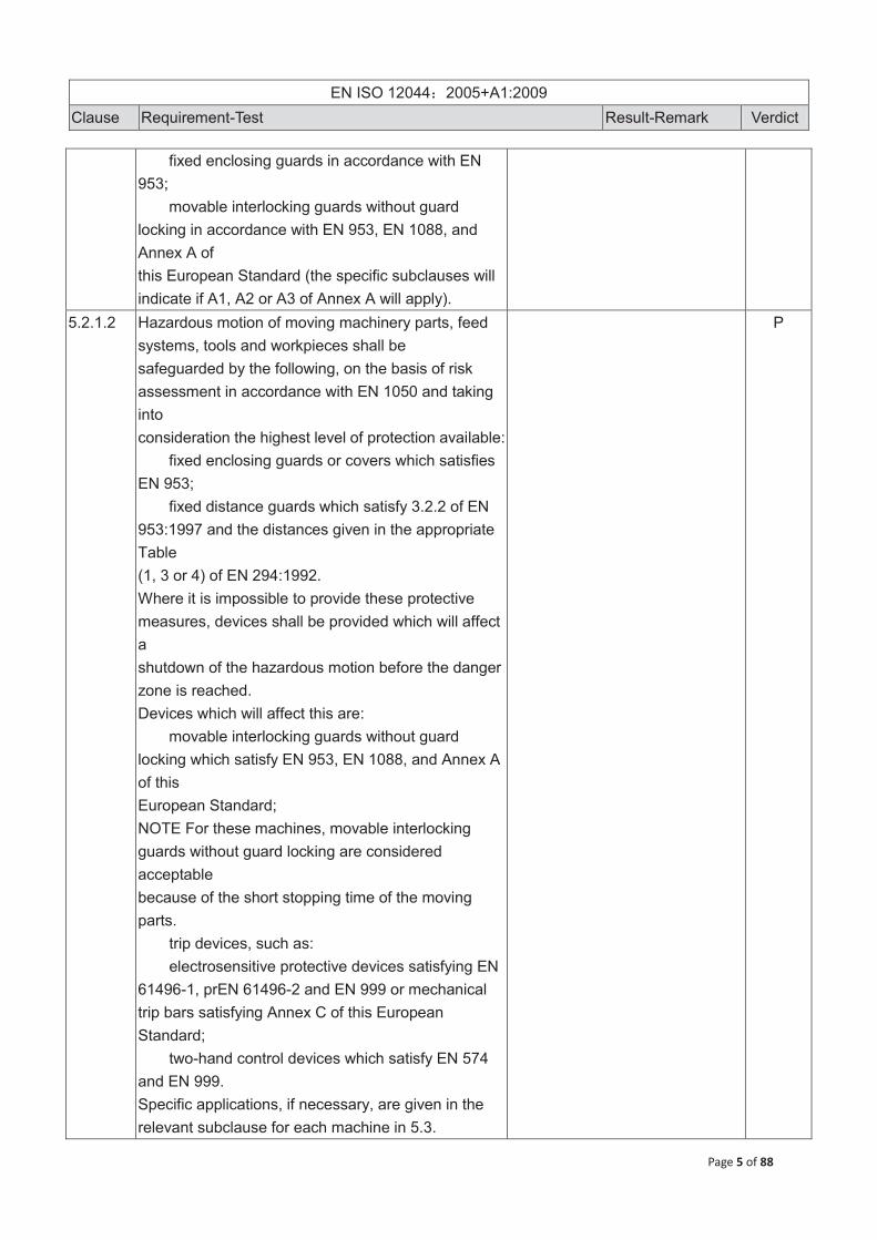
fixed enclosing guards in accordance with EN 953;
movable interlocking guards without guard locking in accordance with EN 953, EN 1088, and Annex A of this European Standard (the specific subclauses will indicate if A1, A2 or A3 of Annex A will apply).
5.2.1.2 Hazardous motion of moving machinery parts, feed systems, tools and workpieces shall be safeguarded by the following, on the basis of risk assessment in accordance with EN 1050 and taking into consideration the highest level of protection available:
fixed enclosing guards or covers which satisfies EN 953;
fixed distance guards which satisfy 3.2.2 of EN 953:1997 and the distances given in the appropriate Table (1, 3 or 4) of EN 294:1992. Where it is impossible to provide these protective measures, devices shall be provided which will affect a shutdown of the hazardous motion before the danger zone is reached. Devices which will affect this are:
movable interlocking guards without guard locking which satisfy EN 953, EN 1088, and Annex A of this European Standard; NOTE For these machines, movable interlocking guards without guard locking are considered acceptable because of the short stopping time of the moving parts.
trip devices, such as: electrosensitive protective devices satisfying EN
61496-1, prEN 61496-2 and EN 999 or mechanical trip bars satisfying Annex C of this European Standard;
two-hand control devices which satisfy EN 574 and EN 999. Specific applications, if necessary, are given in the relevant subclause for each machine in 5.3.
P
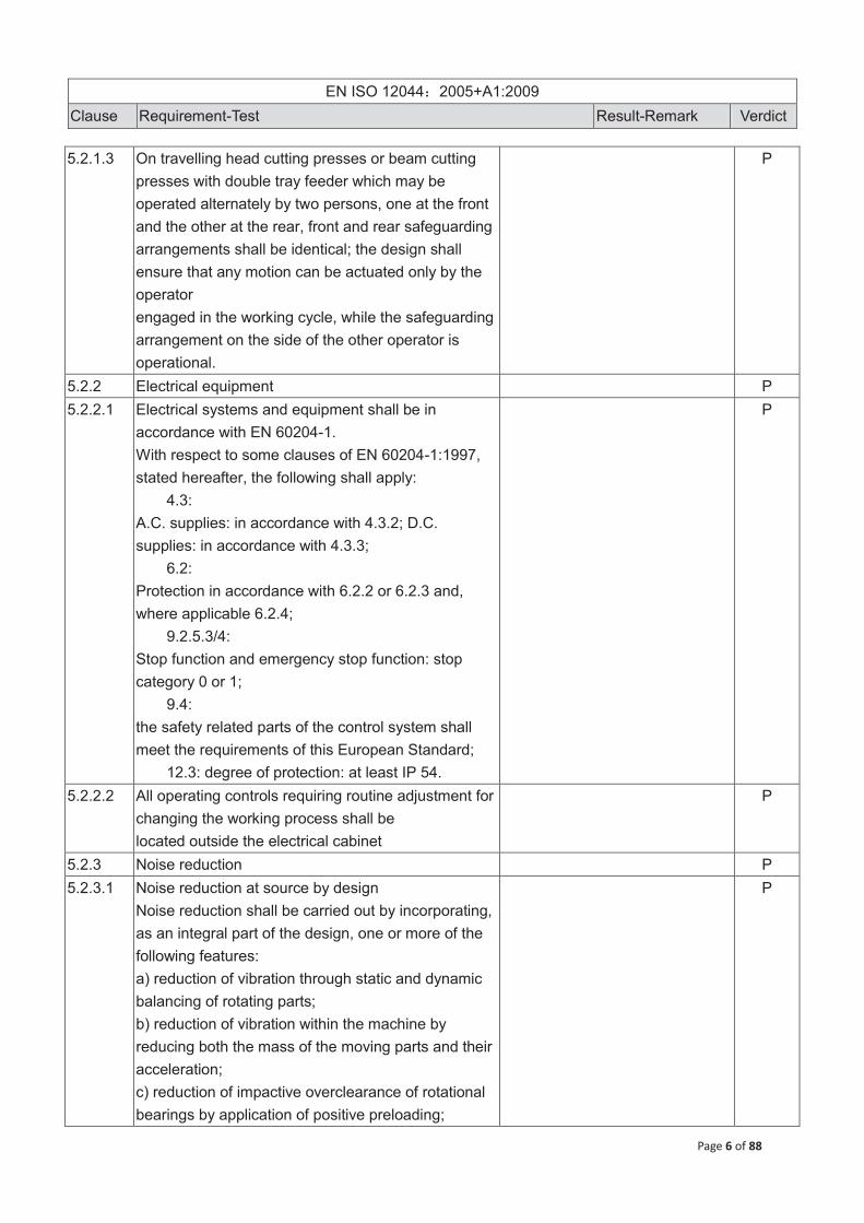
EN ISO 12044 2005+A1:2009
Clause Requirement-Test Result-Remark Verdict
Page 6 of 88
5.2.1.3 On travelling head cutting presses or beam cutting presses with double tray feeder which may be operated alternately by two persons, one at the front and the other at the rear, front and rear safeguarding arrangements shall be identical; the design shall ensure that any motion can be actuated only by the operator engaged in the working cycle, while the safeguarding arrangement on the side of the other operator is operational.
P
5.2.2 Electrical equipment P 5.2.2.1 Electrical systems and equipment shall be in
accordance with EN 60204-1. With respect to some clauses of EN 60204-1:1997, stated hereafter, the following shall apply:
4.3: A.C. supplies: in accordance with 4.3.2; D.C. supplies: in accordance with 4.3.3;
6.2: Protection in accordance with 6.2.2 or 6.2.3 and, where applicable 6.2.4;
9.2.5.3/4: Stop function and emergency stop function: stop category 0 or 1;
9.4: the safety related parts of the control system shall meet the requirements of this European Standard;
12.3: degree of protection: at least IP 54.
P
5.2.2.2 All operating controls requiring routine adjustment for changing the working process shall be located outside the electrical cabinet
P
5.2.3 Noise reduction P 5.2.3.1 Noise reduction at source by design
Noise reduction shall be carried out by incorporating, as an integral part of the design, one or more of the following features: a) reduction of vibration through static and dynamic balancing of rotating parts; b) reduction of vibration within the machine by reducing both the mass of the moving parts and their acceleration; c) reduction of impactive overclearance of rotational bearings by application of positive preloading;
P

EN ISO 12044 2005+A1:2009
Clause Requirement-Test Result-Remark Verdict
Page 7 of 88
d) proper choice and design of the energy-transfer components to eliminate bouncing; e) proper choice and design of transmission components (gears, pulleys, belts, bearings and so on); f) proper design of machine structures taking into account vibration damping and avoidance of structural resonance. This list of technical measures for noise reduction at source gives only examples and is not meant to be complete. These measures are recommended but not compulsory. Other appropriate measures with identical or greater efficacy can be selected taking into account EN ISO 11688-1.
5.2.3.2 Noise reduction by protective devices If it is not possible to achieve the noise reduction at the source by design methods, then the following shall be considered: a) antivibration mountings should be fitted to reduce vibration transmission to the floor; b) sound deadening of pneumatic discharges, vibration damping of hydraulic circuits. Other devices with identical or greater efficacy may be used by the manufacturers.
P
5.2.3.3 Noise reduction by information If consideration of noise reduction at the design stage shows that noise emission levels, after taking all possible technical measures, will be so high that further protection of the operator will be necessary, the information for use shall contain additional information (see 7.2).
P
5.2.4 High pressure fluid To prevent high pressure ejection of fluid or ejection of a part of a burst component, hydraulic and pneumatic systems shall satisfy 4.10 of EN ISO 12100-2:2003, EN 982 and EN 983.
N.A.
5.2.5 Control systems P 5.2.5.1 All machines shall have a start control and a stop P

EN ISO 12044 2005+A1:2009
Clause Requirement-Test Result-Remark Verdict
Page 8 of 88
control fitted at the working zone. The control system shall automatically adopt a safe condition if any of the energy inputs are unavailable. Hydraulic control equipment shall be in accordance with EN 982. Pneumatic control equipment shall be in accordance with EN 983. Electrical control equipment shall be in accordance with 5.2.2 and specific control requirements of individual machines (see 5.3). Design of display and control actuators shall comply with the ergonomic requirements included in EN 894-1, EN 894-2 and EN 894-3.
5.2.5.2 On machines which are equipped with electrosensitive protective devices, cycle re-start may be initiated automatically by this device under the following conditions:
device detects the reestablishment of a safe condition;
recurring access is required for each working cycle;
it is not possible to stand inside the guarded area;
working cycle time of the machine does not exceed one minute. The protective device shall satisfy EN 61496-1 type 4 and shall have a control system complying with category 4 of EN 954-1:1996.
P
5.2 .5.3 On machines where recurring access is required for working, two hand controls which satisfy EN 574 type IIIC and trip devices which satisfy Annex C of this European Standard may only be used as a safeguard provided:
parts of the electrical control system relevant for start or restart are designed in accordance with EN 954-1:1996 category 4; pneumatic or hydraulic controls designed in such a manner that failure of a component cannot initiate hazardous motion automatically in accordance with
P

EN ISO 12044 2005+A1:2009
Clause Requirement-Test Result-Remark Verdict
Page 9 of 88
EN 954-1:1996 category 1 and Annex D.
5.2.5.4 On machines where recurring access is not required for normal operation, the parts of the control system relevant for start or restart shall be not less than EN 954-1:1996 category 3. If electrical position sensors are used, they shall satisfy EN 60947-5-1. Pressure, time or programme controlled commands alone are not permitted.
P
5.2.5.5 Non-electrical safety-related parts of control systems shall:
have the same level of category as the safeguarding used;
have a control system complying with not less than category 1 of EN 954-1:1996. Annex D of this European Standard shall be respected.
P
5.2.5.6 The electrical safety-related parts of control systems shall be designed in such a manner that the failure of any electrical component cannot initiate automatic closing movement, in accordance with category 3 of EN 954-1:1996. The use of programmable electronic systems (PES) shall not reduce any level of safety laid down in this European Standard. Safety related functions shall not rely solely on single channel PES.
This requirement is met by the use of, for example:an additional hardwired control system;
duplicated solid state channels (not programmable);
P
5.2.5.7 The requirements of 5.2.5.4, 5.2.5.5 and 5.2.5.6 do not apply if access to the danger zone is possible only after hazardous motion has been positively blocked by mechanical means, independent of the controls.
P
5.2.5.8 Machines designed for several operating modes, and which can be operated by means of various safety devices, shall be equipped with mode selection devices in accordance with 4.11.9 and 4.11.10 of EN ISO 12100-2:2003.
P

EN ISO 12044 2005+A1:2009
Clause Requirement-Test Result-Remark Verdict
Page 10 of 88
5.2.6 Emergency stop equipment For all machines, except those listed in 5.3.10, the supply disconnecting device can serve the function of emergency stop (see 10.7.5 of EN 60204-1:1997).
P
5.2.7 Ergonomics Machine design shall take into account the ergonomic principles described in 4.8 of EN ISO 12100-2:2003. In particular the design shall take account of:
operating height; operator posture and movement; operator physical strength, especially during
setting, in accordance with EN 1005-3; easy reach and compatibility of control actuators
in accordance with EN 894-1; operator access to the working area in accordance
with EN 547-1 and EN 547-2. If necessary, a suitable platform in accordance with EN ISO 14122-2 shall be provided; the platform shall be non-sloping and the surface shall be made of non-slip material;
possible need for integral lighting in accordance with EN 1837.
P
5.2.8 Danger signals Danger and functional auditory and visual signals adopted shall satisfy the requirements listed in EN 981. They shall be placed in order to satisfy the ergonomic requirements of Clause 4 of EN 981:1996.
P
5.3 Requirements for specific machines 5.3.1 Manual swing arm cutting press
Mechanical hazards referring to danger zones T and L (see Figure 2) shall be safeguarded in accordance with: - combination of 5.3.1.1 and 5.3.1.2 and 5.3.1.4 and 5.3.1.5; - combination of 5.3.1.1 and 5.3.1.3 and 5.3.1.4 and 5.3.1.5.
P
5.3.1.1 A two-hand control device type III A in accordance with EN 574 shall be provided, located on the swing arm, with the related parts of the control system in accordance with not less than category 1 of EN 954- 1:1996 and Annex D of this European Standard, and
P

EN ISO 12044 2005+A1:2009
Clause Requirement-Test Result-Remark Verdict
Page 11 of 88
positioned in accordance with EN 999. 5.3.1.2 One hand control shall be permitted up to a maximum
stroke of 8 mm at the positive selection by the operator (in accordance with 5.2.5.8) and subject to the machine conforming to the following additional criteria: a) control system shall incorporate an automatic changeover to two hand control for strokes exceeding 8mm; b) no single fault shall initiate a cutting stroke; c) no single fault shall cause a changeover from two hand control to one hand control; d) no single fault shall prevent change from one hand control to two hand control; e) single fault in the stroke sensing arrangement shall cause the system to adopt a two hand control; f) there shall be an automatically activated indicator visible to the operator showing the machine to be in a one hand or two hand control condition.
P
5.3.1.3 There shall be a 3 mm x 45° chamfer on the outer edges of the striking surface or, as an alternative, a padding strip with hardness equal to 20 + 5 A shore on 3 sides flush with lower edge of the striking plate of thickness greater than or equal to 12 mm x 12 mm.
P
5.3.1.4 The arm shall be capable of being moved by a force not exceeding 5 N measured at the handle
P
5.3.1.5 The height from floor to table-top (not including cutting pad) shall be equal to (1000 +/- 30) mm.
P
5.3.2 Powered swing arm cutting press Access to the danger zones T, S and L (see Figure 3) shall be protected in accordance with 5.3.2.1 and 5.3.2.2 and 5.3.2.3 and 5.3.2.4 and 5.3.2.5.
P
5.3.2.1 A two hand control device type III A in accordance with EN 574 shall be provided, located outside the danger zone, with the related parts of the control system in accordance with not less then category 1 of EN 954-1:1996 and Annex D of this European Standard, and positioned in accordance with EN 999.
P
5.3.2.2 If, at the front of the machine, the width of the opening between the elements of the fixed guards referred to in 5.3.2.3, exceeds 800 mm, an electro-sensitive protective device of type 2 in
P

EN ISO 12044 2005+A1:2009
Clause Requirement-Test Result-Remark Verdict
Page 12 of 88
accordance with EN 61496-1 and prEN 61496-2 shall be provided, safeguarding the front of the working area, with the related parts of the control system not less than category 1 of EN 954-1:1996 and Annex D of this European Standard, and positioned in accordance with EN 999.
5.3.2.3 Fixed distance guards shall be provided at the sides, rear and the front of the machine, except for the area between the two operating elements of the two-hand control device. The guards shall satisfy the appropriate Tables (2, 3 or 4) of EN 294:1992, EN 349 and EN 953. In verifying the height "a" in Table 2 of EN 294:1992, the reference plane shall be the floor (see Figure.3 of this European Standard, reference point A) on which the machine stands and danger zone shall be the arc of the radius prescribed by the leading edge of the beam in its uppermost position (see Figure. 3 of this European Standard, reference point B).
P
5.3.2.4 The material support area shall be equal to or lower than the level of the cutting pad.
P
5.3.2.5 The movements of the swing arm shall be confined within the guarded area as defined in 5.3.2.3 e.g. by means of positive stop(s), that shall stop the movement before the fencing is reached with the minimum gap in accordance with EN 349.
P
5.3.3 Travelling head cutting press For machines intended to be operated by two persons see 5.2.1.3. The hazards in the zones T, S and L (see Figure 4) shall be safeguarded by alternative combinations of the following requirements, selected as described in Table 2.
P
5.3.3.1 A two hand control device type III A in accordance with EN 574 shall be provided, located outside the danger zone, with the related parts of the control system in accordance with not less then category 1 of EN 954-1:1996 and Annex D of this European Standard for cutting and punching operations, and
P

EN ISO 12044 2005+A1:2009
Clause Requirement-Test Result-Remark Verdict
Page 13 of 88
positioned in accordance with EN 999.
5.3.3.2 Two hand control device type III A in accordance with EN 574 shall be provided, located outside the danger zone, with the related parts of the control system in accordance with not less then category 1 of EN 954-1:1996 and Annex D of this European Standard for horizontal head movement, and positioned in accordance with EN 999.
P
5.3.3.3 There shall be a 3 mm x 45° chamfer on the outer edges of the striking surface or, as an alternative, a padding strip with hardness equal to 20 + 5 A shore on 3 sides flush with lower edge of the striking plate of thickness greater than or equal to 12 mm x12 mm.
P
5.3.3.4 The sides and rear of the machine shall be protected by:
fixed guards which satisfy EN 953 and the distances given in the appropriate Table (1, 3 or 4) of EN 294:1992 and EN 349;
movable interlocking guards which satisfy 4.3.2.2 (Table 2) of EN 294:1992, EN 1088, Annex A1 of this European Standard. These shall have a control system of category 1 of EN 954-1:1996 in compliance with Annex D of this European Standard;
combination of both.
P
5.3.3.5 Any gap between the moving parts (striking elements) and the fixed parts of the press head where the fingers can be crushed shall be at least 30 mm. The striking element return can be actuated if the protection of the electrosensitive protective device is detecting any object inside the surveyed area.
P
5.3.3.6 Where applicable in accordance with the relevant column of Table 2, an electro-sensitive protective device of type 2 in accordance with EN 61496-1 and prEN 61496-2 shall be provided, with the related parts of the control system in accordance with category 2 of EN 954-1:1996 for horizontal head movement and cutting
P

EN ISO 12044 2005+A1:2009
Clause Requirement-Test Result-Remark Verdict
Page 14 of 88
plate downstroke movement. It shall be positioned at the operator access position to zones T, S1, S2 and L (see Figure 4), in accordance with EN 999.
5.3.3.7 Where applicable in accordance with the relevant column of Table 2, an electro-sensitive protective device of type 4 in accordance with EN 61496-1 and prEN 61496-2 shall be provided, with the related parts of the control system in accordance with category 4 of EN 954-1:1996. It shall be positioned at the operator's access position to zones T, S1, S2 and L (see Figure 4) in accordance with EN 999. It shall be connected to the machine control to stop horizontal head movement; the related part of the control system shall satisfy category 4 of EN 954-1:1996. Cutting plate downstroke control shall satisfy category 2 of EN 954-1:1996 because die and material movements have to be down when the cutting plate is removed from the working area and the operator is not directly exposed to the dangerous vertical movement of the cutting plate.
P
5.3.3.8 Where interlocking guards of type A2 of this European Standard are provided in accordance with the relevant column of Table 2, they shall have a control system of category 3 of EN 954-1:1996 and shall be positioned at the operator access position to zones T, S1, S2 and L. Safety distances shall satisfy 4.3.2.2 (Table 2) of EN 294:1992, EN 953 and EN 1088.
P
5.3.3.9 Positive mechanical stops shall be fitted at high level on the side supports of the machine frame to ensure a clearance of at least 120 mm between the leading edge of the travelling head and the frame.
P
5.3.3.10 Feed systems for travelling head presses a) At rear and sides of the device (material loading). Access to the following shall be prevented:
danger space between a set of rolls of a roll feeder;
danger space between two clamps or a clamp and the transporting belt, optionally adopted of a gripper feeder;
P

EN ISO 12044 2005+A1:2009
Clause Requirement-Test Result-Remark Verdict
Page 15 of 88
danger space between the sliding table and its supports of a sliding table:
by means of fixed guards in accordance with EN 953 and 4.3.2.1 (Table 1) of EN 294:1992;
by means of movable interlocking guards in accordance with EN 1088, type A1 of this European Standard and with a control system of category 1 of EN 954-1:1996 in compliance with Annex D of this European Standard;
by means of a combination of both. b) From the operator position, material (e.g. roll) reverse movement which gives rise to danger shall only be permissible where:
interlocking guards are closed and are in accordance with EN 1088, type A1 of this European Standard and have a control system of category 1 of EN 954-1:1996 in compliance with Annex D of this European Standard;
electrosensitive protective device is not detecting any object inside the surveyed area and is of type II in accordance with prEN 61496-2, EN 999 and has a control system of category 2 of EN 954-1:1996;
two-hand control device is of type I in accordance with EN 574, and has a control system of category 1 of EN 954-1:1996 in compliance with Annex D of this European Standard. This restriction is not necessary for material forward movements, actuated e.g. by “hold-to-run” foot pedal or button (see Annex B.1).
5.3.4 Beam cutting press For machines intended to be operated by two persons see 5.2.1.3. Recurring access to the danger zones T and L (see Figure 5) shall be safeguarded by alternative combinations of the following requirements, selected as described in Table 3.
P
5.3.4.1 A two hand control device type III C in accordance with EN 574 shall be provided, located outside the danger zone, with the related parts of the control system in accordance with category 4 of EN 954-1:1996,
P

EN ISO 12044 2005+A1:2009
Clause Requirement-Test Result-Remark Verdict
Page 16 of 88
and positioned in accordance with EN 999. 5.3.4.2 An electrosensitive protective device of type 2, which
satisfies the criteria in EN 61496-1 and prEN 61496-2 shall be provided. It shall be located at the operator access position to the cutting area with a control system of category 2 of EN 954-1:1996. It shall stop all movements except the striking movement return that can be actuated if the protection is detecting any object inside the surveyed area and shall be positioned in accordance with EN 999
P
5.3.4.3 The sides and rear of the machine shall be protected by:
fixed guards which satisfy EN 953 and the distances given in the appropriate Tables (1, 3 or 4) of EN 294:1992;
movable interlocking guards which satisfy 4.3.2.1 (Table 1) of EN 294:1992, EN 1088, Annex A1 of this European Standard and have a control system of category 1 of EN 954-1:1996 in compliance with Annex D of this European Standard;
combination of both. The height of the area to be protected shall be at least equal to the distance between the striking surface and the beam when set to the maximum top position (when the beam moves) or bottom position (when the basement moves) of the vertical stroke.
P
5.3.4.4 Where an electrosensitive protective device of type 4 is provided, it shall satisfy the criteria in EN 61496-1 and in prEN 61496-2. It shall be located at the operator access position to the cutting area and shall have a control system of category 4 of EN 954-1:1996. It shall stop all movements, except the striking movement return that can be actuated if the protection is detecting any object inside the surveyed area, and shall be positioned in accordance with EN 999.
P
5.3.4.5 Where interlocking guards of type A3 of this P

EN ISO 12044 2005+A1:2009
Clause Requirement-Test Result-Remark Verdict
Page 17 of 88
European Standard are provided safety distances shall satisfy 4.3.2.2 (Table 2) of EN 294:1992, EN 953 and EN 1088. They shall have a control system of category 4 of EN 954-1:1996 and shall be positioned at the operator access position to zone T.
5.3.4.6 The machine shall be provided with two valves, to control the beam cutting stroke, and supplied with a check system to prevent uncontrolled dangerous movement in all configurations of machine: e.g. beam downward movement or upward movement.
P
5.3.4.7 To prevent gravity fall of the upper beam, machines with hydraulic beam movement shall be provided with an additional pilot-controlled check seated valve. The check valve is to be fitted as close as possible to the cylinder using flanged pipework or flared unions.
P
5.3.4.8 Feed systems for beam cutting presses a) The requirements shall prevent the access for:
danger space between a set of rolls of a roll feeder;
danger space between two clamps or a clamp and the transporting belt, optionally adopted of a gripper feeder;
danger space between the sliding table and its supports of a sliding table by means of:
fixed guards in accordance with EN 953 and 4.3.2.1 (Table 1) of EN 294:1992;
movable interlocking guards in accordance with EN 1088, type A1 of this European Standard and with a control system of category 1 of EN 954-1:1996 in compliance with Annex D of this European Standard;
combination of both; at rear and sides of the device (material loading). b) From the operator position, material (e.g. roll) reverse movement which gives rise to danger shall only be permissible where:
interlocking guards are closed and are in accordance with EN 1088, type A1 of this European Standard and have a control system of category 1 of
P

EN ISO 12044 2005+A1:2009
Clause Requirement-Test Result-Remark Verdict
Page 18 of 88
EN 954-1:1996 in compliance with Annex D of this European Standard;
electrosensitive protective device of type 2 is fitted and is in accordance with prEN 61496-2, it is positioned in accordance with EN 999 and has a control system of category 2 of EN 954-1:1996 with clear protected area;
two-hand control device type II is fitted and is in accordance with EN 574, and has a control system of category 1 of EN 954-1:1996 in compliance with Annex D of this European Standard. This restriction is not necessary for material forward movements, actuated e.g. by foot pedal.
5.3.5 Beam cutting press with receding head Where the press-head receding motion can be de-selected, and the press can be used in a way that forces the operator to place hands or arms between the beam and the machine basement to collect or move the material or the cutting die, the protection provided in 5.3.5.1 shall be replaced by a protection in accordance with 5.3.4.1, the protection provided in 5.3.5.5 shall be replaced by a protection in accordance with 5.3.4.5 and shall be added the protections provided in 5.3.4.6 and 5.3.4.7. Otherwise access to the danger zones L, T and S (see Figure 6) shall be safeguarded by alternative combinations of the following requirements, selected as described in Table 4.
P
5.3.5.1 A two hand control device type III B in accordance with EN 574 shall be provided, located outside the danger zone, with the related parts of the control system in accordance with category 3 of EN 954-1:1996, and positioned in accordance with EN 999.
P
5.3.5.2 An electrosensitive protective device of type 2, which satisfies the criteria in EN 61496-1 and prEN 61496-2 shall be provided. It shall be positioned at the operator access position to the cutting area and shall have a control system of category 2 of EN
P

EN ISO 12044 2005+A1:2009
Clause Requirement-Test Result-Remark Verdict
Page 19 of 88
954-1:1996. It shall stop all movement except the striking movement return that can be actuated if the protection is detecting any object inside the surveyed area. It shall be positioned in accordance with EN 999.
5.3.5.3 The sides and rear of the machine shall be protected by:
fixed guards which satisfy EN 953 and the distances given in the appropriate Tables (1, 3 or 4) of EN 294:1992;
movable interlocking guards which satisfy 4.3.2.1 (Table 1) of EN 294:1992, EN 1088, Annex A2 of this European Standard and which have a control system of category 4 of EN 954-1:1996;
combination of both. The height of the protected area shall be at least equal to the striking surface point of the beam when set to the maximum open daylight. This condition is met when the front beam surface does not protrude.
P
5.3.5.4 Where an electrosensitive protective device of type 4 is provided it shall satisfy the criteria in EN 61496-1 and prEN 61496-2. It shall be located at the operator access position to the cutting area and shall have a control system of category 4 of EN 954-1:1996. It shall stop all movement except the striking movement return that can be actuated if the protection is detecting any object inside the surveyed area. It shall be positioned in accordance with EN 999.
P
5.3.5.5 Where interlocking guards are provided they shall satisfy 4.3.2.1 (Table 1) of EN 294:1992, EN 1088 and Annex A 3 of this European Standard and shall have a control system of category 4 of EN 954- 1:1996, located at the operator access position to zones T, S 1, and S 2.
P
5.3.5.6 Where a trip device is provided it shall be positioned on the receding head, to stop horizontal movement when any object is met, during its motion. It shall satisfy the criteria in Annex C of this European
P

EN ISO 12044 2005+A1:2009
Clause Requirement-Test Result-Remark Verdict
Page 20 of 88
Standard and shall be positioned in accordance with EN 999.
5.3.6 Beam cutting press with manual tray feeder For machines intended to be operated by two persons see 5.2.1.3. Access to the danger zone L, T and S (see Figure. 7) shall be safeguarded by alternative combinations of the following requirements, selected as described in Table 5.
P
5.3.6.1 A two hand control device type III A in accordance with EN 574, located outside the danger zone, with the related parts of the control system in accordance with not less then category 1 of EN 954-1:1996 and Annex D of this European Standard, and positioned in accordance with EN 999.
P
5.3.6.2 An electrosensitive protective device of type 2, which satisfies the criteria in EN 61496-1 and prEN 61496-2, located at the operator access position to the cutting area and which has a control system of category 2 of EN 954-1:1996. It shall stop all movement except the striking movement return that can be actuated if the protection is detecting any object inside the surveyed area. It shall be positioned in accordance with EN 999.
P
5.3.6.3 The sides and rear of the machine shall be protected by:
fixed guards which satisfy EN 953 and the distances given in the appropriate Tables (1, 3 or 4) of EN 294:1992;
movable interlocking guards which satisfy 4.3.2.1 (Table 1) of EN 294:1992, EN 1088, Annex A1 of this European Standard and which have a control system of category 1 of EN 954-1:1996 in compliance with Annex D of this European Standard;
combination of both. The height of the protected area shall be at least equal to the striking surface point of the beam when
P

EN ISO 12044 2005+A1:2009
Clause Requirement-Test Result-Remark Verdict
Page 21 of 88
set to the maximum open daylight.
5.3.6.4 Where interlocking guards are provided they shall satisfy 4.3.2.2 (Table 2) of EN 294:1992, EN 1088 and Annex A 2 of this European Standard and shall have a control system of category 1 of EN 954- 1:1996 in compliance with Annex D of this European Standard, positioned at the operator access position to zones T and L.
P
5.3.7 Beam cutting press with articulated die carrier not attached to the beam Access to the danger zone L (see Figure 8) shall be safeguarded in accordance with 5.3.7.1, and access to the danger zone T (see Figure 8) shall be safeguarded in accordance with 5.3.7.2 and 5.3.7.3.
P
5.3.7.1 A two hand control device type III B in accordance with EN 574, located outside the danger zone, with the related parts of the control system in accordance with category 3 of EN 954-1:1996, and positioned in accordance with EN 999.
P
5.3.7.2 An electrosensitive protective device of type 2, which satisfies the criteria in EN 61496-1 and prEN 61496-2, located at the operator access position to the cutting area, forming a safety barrier for the operator's head, and preventing movement when the die is outside the cutting area to be discharged. It shall have a control system of category 2 of EN 954-1:1996. It shall stop all movement except the striking movement return that can be actuated if the protection is detecting any object inside the surveyed area. It shall be positioned in accordance with EN 999.
P
5.3.7.3 The sides and rear of the machine shall be protected by:
fixed guards which satisfy EN 953 and the distances given in the appropriate Tables (1, 3 or 4) of EN
P

EN ISO 12044 2005+A1:2009
Clause Requirement-Test Result-Remark Verdict
Page 22 of 88
294:1992; movable interlocking guards which satisfy 4.3.2.1
(Table 1) of EN 294:1992, EN 1088, Annex A2 of this European Standard and which have a control system of category 4 of EN 954-1:1996;
combination of both. 5.3.8 Punching and perforating cutting press with manual
or powered tray feeder Access to the danger zone T (see Figure 9) shall be safeguarded by alternative combinations of the following requirements, selected as described in Table 6
P
5.3.8.1 A two hand control device type III A in accordance with EN 574, located outside the danger zone, with the related parts of the control system in accordance with not less then category 1 of EN 954-1:1996 and Annex D of this European Standard, and positioned in accordance with EN 999.
P
5.3.8.2 An electrosensitive protective device of type 2, which satisfies the criteria in EN 61496-1 and prEN 61496-2 shall be located at the operator access position to the cutting area and shall have a control system of category 2 of EN 954-1:1996. It shall stop all movement except the striking movement return that can be actuated if the protection is detecting any object inside the surveyed area. It shall be positioned in accordance with EN 999.
P
5.3.8.3 The sides and rear of the machine shall be protected by:
fixed guards which satisfy EN 953 and the distances given in the appropriate Tables (1, 3 or 4) of EN 294:1992;
movable interlocking guards which satisfy 4.3.2.1 (Table 1) of EN 294:1992, EN 1088, Annex A2 of this European Standard and which have a control system of category 2 of EN 954-1:1996;
P
5.3.8.4 Interlocking guards which shall satisfy 4.3.2.1 (Table 1) of EN 294:1992, EN 1088, Annex A 2 of this European Standard and with a control system of
P

EN ISO 12044 2005+A1:2009
Clause Requirement-Test Result-Remark Verdict
Page 23 of 88
category 1 of EN 954-1:1996 in compliance with Annex D of this European Standard, positioned at the operator access position to the punching and perforating area and a hold-to-run control device positioned outside the danger zone with a control system of category 1 of EN 954-1:1996 in compliance with Annex D of this European Standard, which satisfies the requirements of Annex B 2.
5.3.8.5 An electrosensitive protective device of type 4, which satisfies the criteria in EN 61496-1 and prEN 61496-2 shall be located at the operator access position to the cutting area and shall have a control system of category 4 of EN 954-1:1996. It shall stop all movement except the striking movement return that can be actuated if the protection is detecting any object inside the surveyed area. It shall be positioned in accordance with EN 999.
P
5.3.9 C-Frame cutting press Access to the danger zone T (see Figure 10) shall be safeguarded in accordance with 5.3.9.1 and 5.3.9.2.
P
5.3.9.1 A two hand control device type III C in accordance with EN 574, located outside the danger zone, with the related parts of the control system in accordance with category 4 of EN 954-1:1996, and positioned in accordance with EN 999.
P
5.3.9.2 The sides and rear of the machine shall be protected by:
fixed guards which satisfy EN 953 and the distances given in the appropriate Table (1, 3 or 4) of EN 294:1992;
movable interlocking guards which satisfy 4.3.2.1 (Table 1) of EN 294:1992, EN 1088, Annex A2 of this European Standard and which have a control system of category 2 of EN 954-1:1996;
any combination of the above measures.
P

EN ISO 12044 2005+A1:2009
Clause Requirement-Test Result-Remark Verdict
Page 24 of 88
5.3.10 Automatic Press For these machines an emergency stopping equipment in accordance with EN 418, stop category 0 or 1, shall be provided with a sufficient number of emergency stopping controls, for example at the defined operator positions. The relevant part of the control system shall be not less than category 1 of EN 954-1:1996. For specific requirements for electrical equipment see 9.2.2, 9.2.5.4 and 10.7 of EN 60204-1:1997. Access to the danger zones T and S (see Figures 11, 12 and 13) shall be safeguarded by alternative combinations of the following requirements, selected as described in Table 7, in accordance with 5.3.10.1 and 5.3.10.2; or 5.3.10.2 and 5.3.10.3.
P
5.3.10.1 Interlocking guards which satisfy 4.3.2.2 (Table 2) of EN 294:1992, EN 1088 and Annex A1 of this European Standard and which have a control system of category 1 of EN 954-1:1996 in compliance with Annex D of this European Standard, positioned at the operator access position to the cutting area.
P
5.3.10.2 The sides and rear of the machine shall be protected by:
fixed guards which satisfy EN 953 and the distances given in the appropriate Tables (1, 3 or 4) of EN 294:1992 and EN 349:1993;
movable interlocking guards which satisfy 4.3.2.1 (Table 1) of EN 294:1992, EN 1088, Annex A1 of this European Standard and which have a control system of category 1 of EN 954-1:1996 in compliance with Annex D of this European Standard;
combination of both.
P
5.3.10.3 An electrosensitive protective device of type 2, which satisfies the criteria in EN 61496-1 and prEN 61496-2 shall be located at the operator access position to the cutting area and shall have a control system of category 2 of EN 954-1:1996. It shall be positioned in accordance with EN 999.
P
6 Verification of the safety requirements and/or measures Aspects of machine design and construction can be
P

EN ISO 12044 2005+A1:2009
Clause Requirement-Test Result-Remark Verdict
Page 25 of 88
subject to verification by inspection, calculation or testing. The criteria for acceptance are self-evident from the requirements. Final verification shall be accomplished with the machine in a fully commissioned condition by checking that:
all "A" and "B" standards referred to in Clause 5 are interpreted correctly;
category of all safety related control systems is correct;
particular specifications (e.g. velocities and forces) are within the defined limits;
all special guards and safety devices are in place, effective and dimensioned in accordance with the values given in the Clause 5;
required information is contained in the instruction handbook. The following table gives a check list of items to be verified:
7 Information for use 7.1 Instructions for use - Instruction Handbook
Basic information shall be provided in accordance with 6.5 of EN ISO 12100-2:2003. The instruction handbook for the machine shall include identification of the machine to which the book refers and, as appropriate, at least the following information relating to the use of the machine:
description and location of controls; modes and means for stopping; instructions for setting and adjustment; information about the residual hazards and
prohibited applications. For example, that these machines shall not to be used to press metals, to calender, to crease, or to cut materials that can not be classified as synthetic for use in the shoe-making industry or similar;
details of requirements for personal protective equipment for the ears;
safety signals and warnings, elements of safe working practices to be included in the training of the
P

EN ISO 12044 2005+A1:2009
Clause Requirement-Test Result-Remark Verdict
Page 26 of 88
operators. 7.2 Information concerning airborne noise and vibration
emissions P
7.2.1 Noise The instruction handbook and the technical documentation describing the machinery, including sales literature, shall:
give the declared noise emission values of the machinery in accordance with EN 12545;
give the reference to the noise test codes upon which the determination of these values is based (see EN 12545 and Annex F of this European Standard). Additionally, if further protection of the operator is necessary, the instruction handbook shall:
recommend the use of low-noise operating modes, or limited time of operation;
recommend the wearing of personal hearing protectors (see EN 352).
P
7.2.2 Vibrations (for hand guided machines only) The instructions shall give the following information concerning vibrations transmitted by hand-guided machinery: - weighted root mean square acceleration value to which the arms are subjected, if it exceeds 2,5 m/s² as determined by the appropriate test code. Where the acceleration does not exceed 2,5 m/s², this shall be mentioned. If there is no applicable test code, the manufacturer must indicate the measurement methods and conditions under which measurements were made.
P
7.3 Marking P 7.3.1 See 6.4 of EN ISO 12100-2:2003. The minimum
markings shall include: name and address of the manufacturer; mandatory marking; year of construction; designation of series or type, if any; rating information (mandatory for electrotechnical
products: voltage, frequency, power, etc).
P

EN ISO 12044 2005+A1:2009
Clause Requirement-Test Result-Remark Verdict
Page 27 of 88
NOTE For machines and their related products intended to be put on the market in EEA, CE marking as defined in the European applicable directive(s), e.g. Machinery, Low Voltage). Other markings which shall be specified if appropriate include:
rating information (for non-electrotechnical products), e.g. working load limit, safe working load, load limits, centre of gravity, gross weight;
special environment condition of use; reference(s) to relevant standard(s); reference to instructions of installation, use and
maintenance; safety signals and warnings: the manufacturer
shall provide signals and/or signs warning for the residual hazards of the machine. Warning signs shall comply with EN 61310-1. The information printed directly on the machine should be permanent and remain legible throughout the expected life of the machine.
7.3.2 Machines shall be marked legibly and indelibly with the following additional information (where applicable): a) net mass; b) information on electrical equipment required by Clause 18 of EN 60204-1:1997; c) data about pressure range for hydraulic systems, see EN 982; supply data and pressure range for pneumatic systems, see EN 983.
P
7.3.3 The manufacturer shall also label appropriate parts of the machine with information concerning the specification of lubricants and hydraulic fluids.
P
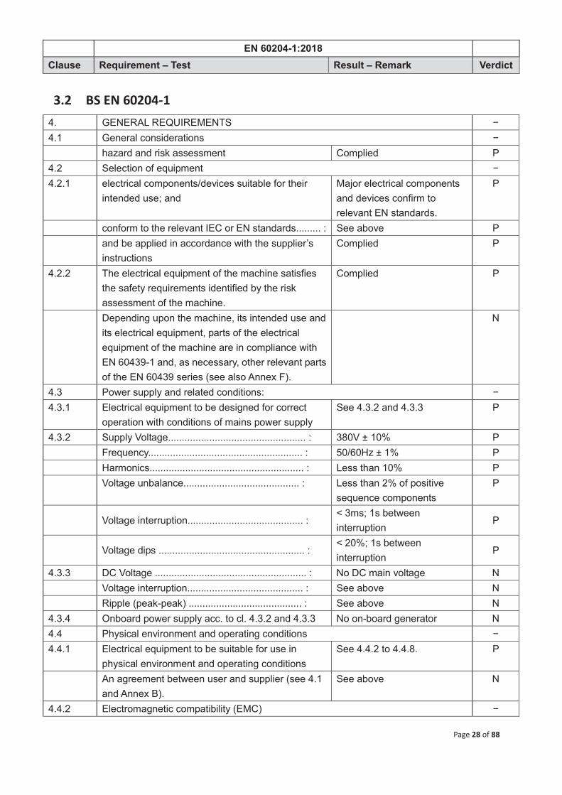
EN 60204-1:2018
Clause Requirement – Test Result – Remark Verdict
Page 28 of 88
3.2 BS EN 60204-1 4. GENERAL REQUIREMENTS − 4.1 General considerations − hazard and risk assessment Complied P 4.2 Selection of equipment − 4.2.1 electrical components/devices suitable for their
intended use; and Major electrical components and devices confirm to relevant EN standards.
P
conform to the relevant IEC or EN standards......... : See above P and be applied in accordance with the supplier’s
instructions Complied P
4.2.2 The electrical equipment of the machine satisfies the safety requirements identified by the risk assessment of the machine.
Complied P
Depending upon the machine, its intended use and its electrical equipment, parts of the electrical equipment of the machine are in compliance with EN 60439-1 and, as necessary, other relevant parts of the EN 60439 series (see also Annex F).
N
4.3 Power supply and related conditions: − 4.3.1 Electrical equipment to be designed for correct
operation with conditions of mains power supply See 4.3.2 and 4.3.3 P
4.3.2 Supply Voltage.................................................. : 380V ± 10% P Frequency........................................................ : 50/60Hz ± 1% P Harmonics........................................................ : Less than 10% P Voltage unbalance.......................................... : Less than 2% of positive
sequence components P
Voltage interruption.......................................... :
< 3ms; 1s between interruption
P
Voltage dips ..................................................... :
< 20%; 1s between interruption
P
4.3.3 DC Voltage ....................................................... : No DC main voltage N Voltage interruption.......................................... : See above N Ripple (peak-peak) ......................................... : See above N 4.3.4 Onboard power supply acc. to cl. 4.3.2 and 4.3.3 No on-board generator N 4.4 Physical environment and operating conditions − 4.4.1 Electrical equipment to be suitable for use in
physical environment and operating conditions See 4.4.2 to 4.4.8. P
An agreement between user and supplier (see 4.1 and Annex B).
See above N
4.4.2 Electromagnetic compatibility (EMC) −

EN 60204-1:2018
Clause Requirement – Test Result – Remark Verdict
Page 29 of 88
Equipment not to generate electromagnetic disturbances above harmful levels ......................... : (applicable generic EMC-standard: EN 61000-6-3 or EN 61000-6-4)
Verified at installation −
Equipment has adequate level of immunity to EMC (applicable generic EMC-standards: EN 61000-6-1 or EN 61000-6-2).................................................:
See above −
4.4.3 Electrical equipment to be capable for correct operation at intended ambient air temperature
Between +0 oC and +40 oC P
4.4.4 Electrical equipment to be capable for correct operation at specified relative humidity: at and
Relative humidity rating of major electrical components and devices is not less than 50% at a temperature of +40 oC
P
4.4.5 Electrical equipment capable of operating correctly at altitudes up to 1000 m above m.s.l.
Up to 1000 m P
4.4.6 Electrical equipment shall be adequately protected against ingress of solid properties and liquids
The equipment has been designed for the IP55
P
4.4.7 Equipment subject to radiation, additional measures to be taken to avoid equipment malfunction
No radiation and additional measures to be taken to avoid equipment malfunction
N
4.4.8 Undesirable effects of vibration, shock and bump avoided
See instruction manual P
4.5 Electrical equipment designed to withstand the effects of transportation and storage within a temperature range of -25 to +55 °C
Temp. range of transportation and storage for major electrical components and devices are within a range of 0 oC to +50 oC
P
A special agreement between supplier and user (see Annex B).
See above N
4.6 Heavy or bulky electrical equipment of the machine provided with suitable means for handling
Information for transportation and installation is provided in instructions and handling devices are equipped where necessary.
P
4.7 Electrical equipment installed and operated in accordance with the supplier’s instruction
See instruction manual P
5. INCOMING SUPPLY CONDUCTOR TERMINATIONS AND DEVICES FOR DISCONNECTING AND SWITCHING OFF
−
5.1 Incoming supply conductor terminal − electrical equipment of a machine connected to a
single power supply Single power supply of 380V 3 230V~, 50/60 Hz
P

EN 60204-1:2018
Clause Requirement – Test Result – Remark Verdict
Page 30 of 88
power supply conductors terminated to main disconnecting device of electrical equipment
Incoming supply is directly connected to the supply terminal of the main circuit breaker. (see installation instruction)
P
neutral conductor ”N” clearly indicated in technical documentation (see 16.1 and also annex B).
No neutral conductor N
no connection between neutral conductor and protective bonding circuit nor combined PEN-terminals.
N
All terminals of incoming supply clearly marked (symbols acc. to EN 60445 and 16.1)
Terminals identified with markings of L1, L2, L3
P
5.2 Terminal for connection to external protective earthing system − Terminal for connection of external protective
conductor provided and marked with ”PE” PE terminal on the bottom of the control panel
P
Cross section of incoming PE conductor acc. to cl. 5.2, table 1
According to clause 5.2, Table 1
P
Terminals allow connection of external protective earth conductors PE (see EN 60445 and also 8.2.6)
Main terminal block P
5.3 Supply disconnecting device − 5.3.1 Power supply disconnecting device provided for
electrical equipment Verified at installation N
5.3.2 Type of power supply disconnecting device: − a) Switch-disconnector, acc. to EN 60947-3 for
appliance category AC-23 B or DC-23 B N
b) Disconnector with or without fuses, with aux. contact (acc. to EN 60947-3)
N
c) Power CB suitable for isolation (acc. to EN 60947-2)
N
d) Any other switching device in accordance with an IEC product standard for that device and which meets the isolation requirements of EN 60947-1 as well as a utilization category defined in the product standard as appropriate for on-load switching of motors or other inductive loads
N
e) plug and socket outlets or appliance couplers for flexible cable supply
N
5.3.3 When the supply disconnecting device is one of the types specified in 5.3.2 a) to d): − Isolator for electrical equipment from supply (acc.
to EN 60947-2) See above N
One OFF (isolated) and one ON position only N

EN 60204-1:2018
Clause Requirement – Test Result – Remark Verdict
Page 31 of 88
Clearly marked with ”0” and ”I” N visible isolating distance or N Position indication which cannot indicate the
OFF-position until all contacts are actually open N
External operating device provided (except power operated CB’s)
N
Colour black or grey preferred, where the external operating means is not intended for emergency operations (see 10.7.4 and 10.8.4)
N
If used as an emergency stop, red/yellow combination selected
N
Locking means provided to lock in OFF-position N In locked position, remote or local closing
prevented N
Disconnection of all live conductors (Exception: TN- supply systems, neutral conductor)
N
Sufficient breaking capacity N When the supply disconnecting device is a plug/socket combination: − – have the switching capability, or be interlocked
with a switching device that has a breaking capacity, sufficient to interrupt the current of the largest motor when stalled together with the sum of the normal running currents of all other motors and/or loads.
N
When the interlocked switching device is electrically operated (for example a contactor) it has an appropriate utilization category
N
– a) to f) of 13.4.5. N Where the supply disconnecting device is a plug/socket combination, − – a switching device with an appropriate utilization
category provided for switching the machine on and off (e.g. by the use of the interlocked switching device described above);
N
5.3.4 Handle of disconnecting device to be easily accessible
See above N
Handle located between 0.6m and 1.9m above service level (upper limit of 1.7 m is recommended)
N
5.3.5 Following circuits not disconnected by supply disconnecting device: − Lighting circuits during maintenance or repair N Plug/socket outlets exclusively used for
maintenance or repair N
Undervoltage protection circuits used for automatic N

EN 60204-1:2018
Clause Requirement – Test Result – Remark Verdict
Page 32 of 88
tripping only at power supply failures Circuits of equipment to remain normally energised
for satisfactory operation N
Control circuits for interlocking purposes N Circuits which are not disconnected by supply disconnecting device: − Permanent warning labels placed in proximity of
supply disconnectors (see 16.1) N
Corresponding statement in maintenance manual, and
N
Warning label in proximity of circuit concerned N or wiring separated from other wiring N or conductors identified by colour taking into
account the recommendation of 13.2.4 N
5.4 Disconnecting devices to prevent unexpected start-up: − Means shall be provided to prevent inadvertent and
/ or mistaken closure of the disconnecting device (see also 5.6)
NFB0 N
Such devices appropriate and convenient for intended use
N
Suitable placed N Readily identifiable (see 16.1) N Devices that fulfill the isolation function provided: − – devices described in 5.3.2, See 5.3.2 N – disconnectors, withdrawable fuse links and
withdrawable links only if located in an enclosed electrical operating area (see 3.19).
N
Devices that do not fulfill the isolation function (for example a contactor switched off by a control circuit) for the following situations only:
– inspections; N – adjustments; N – work on the electrical equipment where: • there is no hazard arising from electric shock (see
Clause 6) and burn; N
• the switching off means remains effective throughout the work;
N
• the work is of a minor nature (for example replacement of plug-in devices without disturbing existing wiring).
N
5.5 Devices provided for disconnecting (isolating) electrical equipment to enable work to be carried out when it is de-energized and isolated.
N
Such disconnecting devices appropriate and N

EN 60204-1:2018
Clause Requirement – Test Result – Remark Verdict
Page 33 of 88
convenient for intended use and Suitably located and N readily identifiable to which part it serves (see
16.1). N
Provided with adequate means to prevent unauthorised, inadvertent and /or mistaken closing (see also 5.6)
N
Supply-disconnecting device used (see 5.3) N Disconnecting device provided for each separated
part of the machine or partial machine where necessary
N
In addition to the supply disconnecting device as above: − Devices described in 5.3.2; N Disconnectors, fuse links etc. used only in
enclosed electrical operating areas (see 3.15) and N
and relevant information is provided with the electrical equipment (see 17.2 b) 9) and b)12)).
N
5.6 Devices acc. to cl. 5.4 and 5.5 that are located outside an enclosed electrical operating area
N
Means provided with device to secure them in the OFF position (disconnected state), (for example by provisions for padlocking, trapped key interlocking)
N
When so secured, remote as well as local reconnection shall be prevented.
N
Other means of protection against reconnection (for example warning labels in accordance with 16.1) used for non-lockable disconnecting devices (for example withdrawable fuse-links, withdrawable links)
N
Locking device not necessary for plug/ socket outlet combinations, if located in a suitable manner and
N
Under immediate supervision of the person carrying out the work
N
6 PROTECTION AGAINST ELECTRIC SHOCK − 6.2 Protection against direct contact: − 6.2.1 - by means of protection by enclosure All live parts were protected
by enclosure or integrated insulation with the approved components.
P
- by means of insulation of live parts See 6.2.3 P - by means of protection against residual voltages See 18.5 P

EN 60204-1:2018
Clause Requirement – Test Result – Remark Verdict
Page 34 of 88
6.2.2 Protection by enclosure: − Live parts located inside enclosures conform to
relevant requirements of clauses 4, 11 and 14 Protection against direct contact at least IP2X or IPXXB
IP 55 Motor P
Where top surfaces of enclosures are readily accessible, degree of protection against direct contact is IP4X or IPXXD.
N
Opening of enclosure possible only under following conditions: a) use of a key or a tool. Special requirements for
enclosed electrical operating areas may apply N
live parts inside of doors with protection degree of IP1X or IPXXA
N
live parts likely to be touched during resetting or adjustment with protection degree IP2X or IPXXB
N
b) disconnection of live parts inside enclosure prior to opening of enclosure
N
at door interlocking safety circuit, door will open only when main isolator is in open position
N
- opening of disconnector possible at all times while interlock is defeated
See above b) N
- and lock the disconnecting device in the OFF (isolated) position or otherwise prevent unauthorised closure of the disconnecting device;
N
- upon closing the door, interlock is automatically restored
N
– all live parts, that are likely to be touched when resetting or adjusting devices intended for such operations while the equipment is still connected, are protected against direct contact to at least IP2X or IPXXB and other live parts on the inside of doors are protected against direct contact to at least IP1X or IPXXA;
N
– relevant information is provided with the electrical equipment (see 17.2 b)9) and b)12)).
N
Means provided to restrict access to live parts behind doors not directly interlocked with the disconnecting means to skilled or instructed persons. (See 17.2 b)12)).
N
All parts remaining live after switching off mains supply to be protected against direct contact with at least IP2X or IPXXB
N

EN 60204-1:2018
Clause Requirement – Test Result – Remark Verdict
Page 35 of 88
Such parts marked with warning symbol acc. to cl.16.2.1 (see also 13.2.4 for identification of conductors by colour).
N
Excepted from this requirement for marking are: − - Parts that can be live only due to connection to
interlocking circuits, distinguished by colour as potentially live acc. to cl. 13.2.4
N
- Terminals of supply disconnecting device when latter mounted alone in a separate enclosure
N
c) opening of doors without use of key or tool and without disconnection of live parts possible only when all live parts are protected against direct contact by IP2X or IPXXB
N
where protection is provided by barriers, tools required for their removal or
N
all live parts automatically disconnected when barrier is removed
N
6.2.3 Protection by insulation of live parts: − Live parts completely covered with insulation All the liver parts insulated
appropriately for intended use in the equipment
P
insulation can be removed only by destruction Complied P insulation capable to withstand mechanical,
chemical, electrical and thermal stress occurring under normal service conditions
Complied P
Paint, varnish lacquer etc. not used as insulation Complied P 6.2.4 Protection of residual voltage: − Live parts with residual voltage > 60V after
disconnection, to be discharged to ≤ 60V within 5s after disconnection, except for components with charges ≤ 60 μC
see 18.5 for test results P
Where pins of plugs or similar devices after withdrawal are exposed, discharge time ≤ 1s,
None N
Or, such conductors protected against direct contact by at least IP2X or IPXXB
See above N
if above requirements cannot be achieved (for example a warning notice in accordance with 16.1), additional disconnecting devices or appropriate warning devices shall be applied. (see cl. 12.7.4)
See above N
6.2.5 Protection by barriers acc. to EN 60364-4-41 cl. 412.2
No barriers for protection N
6.2.6 Protection by placing out of reach or protection by obstacles acc. to EN 60364-4-41, cl. 412.4 and
No such protection N

EN 60204-1:2018
Clause Requirement – Test Result – Remark Verdict
Page 36 of 88
412.3)
For collector wire- or bar systems, with protection less than IP2X, see cl. 13.8.1
See above N
6.3 Protection against indirect contact: − 6.3.2 Measures to prevent the occurrence of a hazardous touch voltage − 6.3.2.2 use of class II electrical devices or apparatus
(double insulation, reinforced insulation or by equivalent insulation acc. to EN 61140)
External wires and cables have been protected by use of double insulation or reinforced insulation.
P
use of switchgear and controlgear assemblies with total insulation acc. to EN 60439-1
See above N
application of supplementary or reinforced insulation acc. to EN 60364-4-41, 413.2
See above N
6.3.2.3 Electrical separation of an individual circuit to prevent hazardous touch voltage acc. to EN 60364-4-41, cl. 413.5
N
6.3.3 Protection by automatic disconnection of supply by means of: − Protective bonding of exposed conductive parts
(see 8.2.3), and Complied P
a) Overcurrent protective device for automatic disconnection on detection of an insulation fault in a TN-system, or
The advice found in manual, the device provided by user
P
b) Residual current protective devices to initiate the automatic disconnection of the supply on detection of an insulation fault from a live part to exposed conductive parts or to earth in TT systems, or
N
c) Use of insulation monitoring or residual current protective devices to initiate automatic disconnection in a IT-System, and
N
Except where a protective device is provided to interrupt the supply in the case of the first earth fault, an insulation monitoring device shall be provided to indicate the occurrence of a first fault from a live part to exposed conductive parts or to earth, initiating an audible and/or visual signal which shall continue as long as the fault persists.
N
Where automatic disconnection is provided in accordance with a) and disconnection within the time specified in Clause A.1 cannot be assured, supplementary bonding shall be provided as necessary to meet the requirements of Clause A.3.
N
6.4 Protection by application of PELV circuit which have to fulfil following requirements: −

EN 60204-1:2018
Clause Requirement – Test Result – Remark Verdict
Page 37 of 88
6.4.1 a) nominal voltage not to exceed 25 AC (r.m.s.) or 60 DC (ripple-free) or
N
6VAC or 15VDC for all other cases N b) one side of PELV- circuit or one point of source
of supply to be connected to PE- circuit N
c) live parts of PELV- circuits to be electrically separated from other live circuits.
N
Electrical separation equal as required for safety isolating transformers (see IEC 61558-1 and IEC 61558-2-6)
N
d) conductors of each PELV circuit to be physically separated from those of any other circuit.
N
If not practicable, insulation provisions acc. to cl. 13.1.3 shall be applied
N
e) plugs and socket outlets for PELV- circuits shall conform to following requirements:
−
plugs shall not be able to enter socket outlets of other voltage systems
None N
socket outlets shall not admit plugs of other voltage systems
None N
6.4.2 Sources for PELV- circuits to be one of the following: − safety isolating transformers acc. to IEC 61558-1
and IEC 61558-2-6 N
source of current providing a degree of safety, equivalent to safety isolating transformers
N
electrochemical or other source, independent of circuit with higher voltage
N
electronic power supply conforming to appropriate standards
N
7 PROTECTION EQUIPMENT − 7.2 Overcurrent protection: − 7.2.1 Overcurrent protection device provided See manual N 7.2.2 Overcurrent protective device at incoming feeder to
the electrical equipment (see to cl. 7.2.10 and cl. 18.5)
N
Electrical equipment supplier state data for overcurrent protective device
See instructions N
7.2.3 Power circuits: − Overcurrent protective devices applied to each
live conductors except for neutral earth conductor N
The following conductors, as applicable, are not disconnected without disconnecting all associated live conductors:

EN 60204-1:2018
Clause Requirement – Test Result – Remark Verdict
Page 38 of 88
– the neutral conductor of a.c. power circuits; None N – the earthed conductor of d.c. power circuits; None N – d.c. power conductors bonded to exposed
conductive parts of mobile machines. No mobile machines N
Cross sectional area of neutral conductor to be at least equal to phase conductor, no overcurrent protective/ disconnecting device required
P
For neutral earth conductors with cross sections smaller than phase conductors, measures acc. to 524 of IEC 60364-5-52 will apply
P
For IT-systems use of neutral earth conductor (N) is not recommended. Nevertheless if a N-conductor is used, measures acc. to cl. 473.3.2.2 of IEC 60364-4-43 shall apply.
No IT-systems N
7.2.4 Control circuits: − Conductors of control circuits directly connected to
supply voltage and circuits feeding control voltage transformers protected against overcurrent acc. to cl. 7.2.3
N
Conductors of control circuits supplied by a control circuit transformer or d.c. supply are protected against overcurrent (see also 9.4.3.1):
– in control circuits connected to the protective bonding circuit, by inserting an overcurrent protective device into the switched conductor;
N
– in control circuits not connected to the protective bonding circuit: − - where the same cross sectional area conductors
are used in all control circuits, by inserting an overcurrent protective device into the switched conductor, and;
N
- where different cross sectional areas conductors are used in different sub-circuits, by inserting an overcurrent protective device into both switched and common conductors of each sub-circuit.
N
7.2.5 Socket outlets and their associated conductors: − Overcurrent protection devices for socket outlets
provided for non-earthed live conductors of each circuit feeding such socket outlets
N
7.2.6 Lighting circuits: − All unearthed conductors of local lighting circuits
protected by overcurrent protective devices N
7.2.7 Transformers: − Transformers protected against overcurrent acc. to
with the manufacturer’s instructions. N

EN 60204-1:2018
Clause Requirement – Test Result – Remark Verdict
Page 39 of 88
Avoid unnecessary tripping due to overcurrent caused by magnetising inrush currents
N
Avoid temperature rise of transformer winding in excess of its permitted of its insulation class of transformer in case of short circuit at secondary terminals
N
Type and setting of overcurrent protective device acc. to recommendations of transformer manufacturer
N
7.2.8 Location of protective devices: − Overcurrent protective device located at point
where a reduction in the cross sectional area of the conductors or another change reduces the current-carrying capacity of the conductors, except
N
Current carrying capacity of conductors at least equal to that the load, and
N
The part of the conductor between the point of reduction of current-carrying capacity and the position of the overcurrent protective device not longer than 3 meters, and
N
Conductor installed in such a manner as to reduce the possibility of a short-circuit, for example, protected by an enclosure or duct
N
7.2.9 Overcurrent protective devices: − Rated short-circuit breaking capacity at least equal
to prospective fault current at point of installation N
Current other than those coming from supply side taken into account
N
Reduced breaking capacity is permitted, where another protective device is installed at supply side with the necessary breaking capacity
N
Back-up protection carefully checked, no destruction of conductor or overcurrent protective device may result
N
Co-ordination with other protective devices in circuit required
N
Where fuses are provided as overcurrent protective devices, a type readily available in the country of use shall be selected, or arrangements shall be made for the supply of spare parts.
N
7.2.10 Rating and setting of overcurrent protective devices: −

EN 60204-1:2018
Clause Requirement – Test Result – Remark Verdict
Page 40 of 88
The rated current or setting of an overcurrent protective device is determined by the current carrying capacity of the conductors to be protected in accordance with 12.4, D.2 and the maximum allowable interrupting time t in accordance with Clause D.3, taking into account the needs of co-ordination with other electrical devices in the protected circuit.
See manual N
Settings of overcurrent protective devices appropriately listed in technical documentation
N
7.3 Protection of motors against overheating: − 7.3.1 General − Protection of motors against overheating provided
for each motor rated at more than 0,5 kW See manual P
In applications where an automatic interruption of the motor operation is unacceptable (for example fire pumps), the means of detection shall give a warning signal to which the operator can respond.
N
Overload protection achieved by overload protection (7.3.2), over-temperature protection (7.3.3) or current-limiting protection (7.3.4)
See manual P
Automatic restarting of motors prevented after operation of overload protective device, to avoid cause of a hazardous condition
N
7.3.2 Overload protection − Current overload detection provided for each live
conductor except for neutral conductor EN 60034-1 certified induction motor
P
However, where the motor overload detection is not used for cable overload protection (see also Clause D.2), the number of overload detection devices may be reduced at the request of the user (see also Annex B).
N
For motors having single phase or d.c. power supply, detection in only one unearthed live conductor is permitted
See manual P
7.3.3 Over-temperature protection − The provision of motors with over-temperature
protection (see IEC 60034-11) recommended in situations where the cooling can be impaired (for example dusty environments).
Verified in installation N
Depending upon the type of motor, protection under stalled rotor or loss of phase conditions is not always ensured by over-temperature protection,
N

EN 60204-1:2018
Clause Requirement – Test Result – Remark Verdict
Page 41 of 88
and additional protection should then be provided.
Over-temperature protection also recommended for motors that cannot be overloaded (for example torque motors, motion drives that are either protected by mechanical overload protection devices or are adequately dimensioned), where the possibility of over-temperature exists (for example due to reduced cooling).
N
7.3.4 Current limiting protection − Where protection against the effects of overheating
in three phase motors is achieved by current limitation, the number of current limitation devices may be reduced from 3 to 2 (see 7.3.2).
EN 60034-1 certified induction motor
P
For motors having single phase a.c or d.c. power supplies, current limitation in only one unearthed live conductor is permitted.
N
7.4 Abnormal temperature protection: − Resistance heating or similar devices which cause
excessive heat, equipped with suitable overtemperature (for example, due to short-time rating or loss of cooling medium) detection
None N
7.5 Protection against supply interruption or voltage reduction and subsequent restoration
Undervoltage protection provided for applications where loss of supply or undervoltage causes a hazardous condition
No malfunctioning resulting from a voltage drop or supply interruption.
N
If interruption or reduction of supply voltage is allowed for a short period of time, delayed undervoltage protection provided.
See above N
Undervoltage protection not impair any stopping control of the machine
See above N
Upon restoration of supply voltage, automatic or unexpected restarting of machine prevented
No automatic restarting possible
N
Undervoltage protection to initiate appropriate control responses to ensure co-ordination the groups of machines working together
See above N
7.6 Motor overspeed protection: − Overspeed protection provided where
overspeeding causes a hazardous condition N
Overspeed protection initiates appropriate control response and prevents automatic restarting
N

EN 60204-1:2018
Clause Requirement – Test Result – Remark Verdict
Page 42 of 88
The overspeed protection operates in such a manner that the mechanical speed limit of the motor or its load is not exceeded.
N
7.7 Earth fault / residual current protection: − To reduce damage to equipment due to earth fault
currents less than the detection level of the overcurrent protection, earth fault/residual protection used
N
Detection level for earth fault protection set as low as possible
N
7.8 Phase sequence protection: − Protection from incorrect phase sequence of
supply voltage provided N
7.9 Protection against overvoltages due to lightning strike or switching action: − Protective devices for the suppression of
overvoltages caused by lightning strikes or switching surges provided
N
Devices for suppression of overvoltages due to lightning, connected at incoming terminals of the supply disconnecting device
N
Devices for suppression of overvoltages due to switching surges connected across terminals of all equipment requiring such protection
N
8 EQUIPOTENTIAL BONDING − 8.2.1 General: − All parts of protective bonding circuit capable to
withstand max. thermal and mechanical stress, caused by earth-fault currents
See 8.2.2 to 8.2.8 P
A supplementary bonding conductor provided, where the conductance of structural parts of the electrical equipment or of the machine is less than that of the smallest protective conductor connected to the exposed conductive parts.
No supplementary bonding conductor
N
This supplementary bonding conductor having a cross-sectional area not less than half that of the corresponding protective conductor.
See above N
When an IT distribution system is used, machine structure will be part of the protective bonding circuit in conjunction with insulation monitoring. See 6.3.3 c).
No IT distribution system N
Conductive structural parts of equipment in accordance with 6.3.2.2 need not be connected to the protective bonding circuit.
All accessible conductive parts connected to the protective bonding circuit
N

EN 60204-1:2018
Clause Requirement – Test Result – Remark Verdict
Page 43 of 88
Extraneous conductive parts which form the structure of the machine need not be connected to the protective bonding circuit where all the equipment provided is in accordance with 6.3.2.2.
See above N
Exposed conductive parts of equipment in accordance with 6.3.2.3 shall not be connected to the protective bonding circuit.
See above N
8.2.2 Protective conductors: − Identification and marking of protective conductors
acc. to cl. 13.2.2 See 13.2.2 P
Copper conductors used as protective conductors Complied P Other conductor materials allowed, if cross section
of such conductors is not less than 16 mm2 No conductor other than copper used
N
Cross-sectional area of protective conductors determined acc. to IEC 60364-5-54, cl. 543 or EN 60439-1, cl. 7.4.3.1.7, table 4
P
Relationship between cross-section area of phase conductor and PE acc. to table 1 (see 5.2). See also 8.2.8.
See above P
8.2.3 Continuity of protective bonding circuit: − All exposed conductive parts connected to
protective bonding circuit acc. to 8.2.1. (see 8.2.5 for exception)
All exposed conductive parts connected to the protective bonding circuit
P
In case of removal of parts of PE system, remaining parts not to be interrupted
N
Current-carrying capacity of connections and bonding points not impaired by mechanical, chemical or electrochemical influences
Complied P
Particular consideration should be given if enclosure consists of aluminium and its alloys
None N
Metal conduits and cable armouring not used as protective conductors but connected to protective bonding circuit
No flexible metal conduits and metallic cable sheaths used as protective conductors
P
Protective conductor in cables exposed to damage (e.g. flexible trailing cables) is ensured by appropriate measures (e.g. monitoring)
Complied P
For continuity of the protective conductor using collector wires, collector bars and slip-ring assemblies, see 12.7.2
None N
8.2.4 Exclusions of switching devices from protective bonding circuit: − Protective bonding circuit not incorporate a
switching-/overcurrent protective device No such devices in protective bonding circuit
P

EN 60204-1:2018
Clause Requirement – Test Result – Remark Verdict
Page 44 of 88
No means of interruption of the protective bonding conductor provided.
Complied P
Exception: links for test or measurement purposes that cannot be opened without the use of a tool and that are located in an enclosed electrical operating area.
None N
Where the continuity of the protective bonding circuit can be interrupted by means of removable current collectors or plug/socket combinations, the protective bonding circuit shall be interrupted by a first make last break contact.
None N
This also applies to removable or withdrawable plug-in units (see also 13.4.5).
See above N
8.2.5 Equipment parts that need not to be connected to protective bonding circuit: − Parts which cannot be touched on large surfaces or
grasped by hand due to its small size (less than approx. 50 x 50 mm), small parts such as screws, rivets, nameplates (see also 410.3.3.5 of IEC 60364-4-41) or
Nameplate, screws, etc. P
are located in such way, that either contact with live parts or an insulation failure is unlikely
Complied P
8.2.6 Protective conductor connecting points: − PE conductor connecting points have no other
functions and not used for connection of appliances or other parts
No other function than PE connection
P
Each protective conductor connecting point identified by using the symbol IEC 60417-5019 (DB:2002-10)
Complied P
or with the letters PE, the graphical symbol being preferred, or by use of the bicolour combination GREEN-AND-YELLOW, or by any combination of these.
See above (see 5.2) N
8.2.7 Mobile machines − On mobile machines with on-board power supplies,
the protective conductors, the conductive structural parts of the electrical equipment, and those extraneous conductive parts which form the structure of the machine connected to a protective bonding terminal
No mobile machines N
Where a mobile machine is also capable of being connected to an external incoming power supply, this protective bonding terminal fixed to the connection point for the external protective
See above N

EN 60204-1:2018
Clause Requirement – Test Result – Remark Verdict
Page 45 of 88
conductor.
8.2.8 Additional protective bonding requirements for electrical equipment having earth leakage currents higher than 10 mA a.c. or d.c.
−
Where electrical equipment has an earth leakage current (for example adjustable speed electrical power drive systems and information technology equipment) > 10 mA a.c. or d.c. in
any incoming supply, for the associated protective bonding circuit: a) the protective conductor having a
cross-sectional area of at least 10 mm2 Cu or 16 mm2 Al, through its total run, or
Earth leakage currents < 10 mA a.c. or d.c.
N
b) where the protective conductor has a cross-sectional area of less than 10 mm2 Cu or 16 mm2 Al, a second protective conductor of at least the same cross-sectional area provided up to a point where the protective conductor has a cross-sectional area not less than 10 mm2 Cu or 16 mm2 Al, or
See above N
c) automatic disconnection of the supply in case of loss of continuity of the protective conductor.
See above N
To prevent difficulties associated with electromagnetic disturbances, the requirements of 4.4.2 also apply to the installation of duplicate protective conductors.
See above N
In addition, a warning label provided adjacent to the PE terminal, and where necessary on the nameplate of the electrical equipment.
See above N
Information about the leakage current and the minimum cross sectional area of the external protective conductor (see 17.2 b) 1)).
See above N
8.3 Functional bonding − Protection against maloperation as a result of
insulation failures by connecting to a common conductor in accordance with 9.4.3.1.
No functional bonding N
For recommendations regarding functional bonding to avoid maloperation due to electromagnetic disturbances, see 4.4.2.
See above N
8.4 Measures to limit the effects of high leakage current − Equipment having high leakage current by
connection of that equipment to a dedicated supply transformer having separate windings
Earth leakage currents < 10 mA a.c. or d.c.
N
The protective bonding circuit connected to exposed conductive parts of the equipment and, in addition, to the secondary winding of the
See above N

EN 60204-1:2018
Clause Requirement – Test Result – Remark Verdict
Page 46 of 88
transformer.
The protective conductor(s) between the equipment and the secondary winding of the transformer in compliance with one or more of the arrangements described in 8.2.8.
See above N
9 CONTROL CIRCUITS AND CONTROL FUNCTIONS − 9.1.1 Control circuits supplied by transformers have
separately isolated windings Verified in installation N
If several transformers used, secondary voltages in phase
See above N
DC- control circuits connected to PE circuit supplied from a separate winding of the control circuit transformer or supplied from another control circuit transformer
N
Transformers not mandatory for machines with a single motor starter and maximum of two control devices
See above N
9.1.2 Nominal voltage not exceed 277VAC when supplied from a transformer
N
9.1.3 Control circuits provided with overcurrent protection
N
9.2 Control functions: − 9.2.1 Start function initiated by energising relevant
starting circuit N
9.2.2 Stop functions: − Stop category 0: Stopping by immediate removal of
power to machine actuators N
Stop category 1: A controlled stop with power available to machine actuators. Then removal of power when stop condition has been achieved.
See above N
Stop category 2: A controlled stop with power left available to machine actuators
See above N
9.2.3 Mode of operations of machines: − Hazardous condition, resulting from a mode
selection, prevented by suitable means N
Mode selection does not start up the machine N Separate control action required by operator N Relevant safety functions and/or protective
measures implemented for each specific operating mode
N
Indication of selected operating mode provided N 9.2.4 If safety functions and/or protective measures (for example for setting or −

EN 60204-1:2018
Clause Requirement – Test Result – Remark Verdict
Page 47 of 88
maintenance purposes) need to be suspended, protection be ensured by: – disabling all other operating (control) modes; and Complied N – other relevant means (see 4.11.9 of ISO 12100-2:2003), that can include, for
example, one or more of the following: −
- initiation of operation by a hold-to-run device or by a similar control device;
None N
- a portable control station with an emergency stop device and, where appropriate, an enabling device.
None N
Where a portable control station is in use, initiation of motion be possible only from that control station;
None N
- a cableless control station with a device to initiate stop functions in accordance with 9.2.7.3 and, where appropriate, an enabling device.
None N
Where a cableless control station is in use, initiation of motion be possible only from that control station;
None N
- limitation of the speed or the power of motion; None N - limitation of the range of motion. None N 9.2.5 Operation: − 9.2.5.1 Necessary safety functions and/or protective
measures (for example interlocks (see 9.3)) provided for safe operation
N
Unintended or unexpected movement of machine prevented after any stopping of machine
No such movement likely N
Where a machine has more than one control station, measures be provided to ensure that initiation of commands from different control stations do not lead to a hazardous situation.
N
9.2.5.2 Start of operation possible only when all relevant safety functions and/or protective measures are functional, except for conditions stated in cl.9.2.4
N
For machines where under certain operating conditions no safety functions and/or protective measures can be applied, manual control of such operations by hold-to- run controls, together with enabling devices
N
Suitable interlocks provided to secure correct sequential start
N
In the case of machines requiring the use of more than one control station to initiate a start:
−
Each control station has a separate, manually actuated start control device
N

EN 60204-1:2018
Clause Requirement – Test Result – Remark Verdict
Page 48 of 88
The conditions to initiate a start be: − All required conditions for automatic machine
operation are fulfilled, and N
All start control devices in released position (OFF), then
N
All start control devices simultaneously actuated (see 3.6)
N
9.2.5.3 Stop functions of stop categories 0, 1 and/or 2 shall be provided, based on a risk-assessment and functional requirements of the machine
N
Stop functions override related start functions (see 9.2.5.2)
N
Facilities provided for connection of protective devices / interlocks
N
If such protective device/ interlock causes a machine stop, it may be necessary to send such condition to the logic of the control system
N
Resetting of stop function must not initiate any hazardous situation
N
Where more than one control station is provided, stop commands from any control station be effective when required by the risk assessment of the machine.
N
9.2.5.4 Emergency operations (emergency stop, emergency switching off) − 9.2.5.4.1 General − Both of emergency stop and emergency switching
off functions of the emergency operations listed in Annex E initiated by a single human action.
N
Once active operation of an emergency stop (see 10.7) or emergency switching off (see 10.8) actuator has ceased following a command, the effect of this command be sustained until it is reset.
N
This reset possible only by a manual action at that location where the command has been initiated.
N
The reset of the command do not restart the machinery but only permit restarting.
N
Not be possible to restart the machinery until all emergency stop commands have been reset.
N
Not be possible to reenergize the machinery until all emergency switching off commands have been reset.
N
9.2.5.4.2 Design of emergency stop equipment, including functional aspects acc. to ISO 13850.
N

EN 60204-1:2018
Clause Requirement – Test Result – Remark Verdict
Page 49 of 88
Emergency stop acts either as stop of category 0 or as stop of category 1 (see 9.2.2)
N
For determination of category of emergency stop, see risk assessment
N
In addition to the requirements for stop (see 9.2.5.3), − Emergency stop has priority over all other functions
and over all modes of operation N
Power to machine actuators that can cause hazardous situation(s) either removed immediately (stop category 0) or controlled in such a way to stop the hazardous motion as quickly as possible (stop category 1) without creating other hazards
N
Resetting must not initiate a restart N 9.2.5.4.3 Functional aspects of emergency switching-off function are given in 536.4 of IEC
60364-5-53 and should be provided where:
Protection against direct contact is achieved only by placing out of reach or by obstacles
None N
There is the possibility of other hazards or damage by electricity
None N
Emergency switching- off is accomplished by switching off the relevant incoming supply by electromechanical switching devices, effecting a stop category 0 of machine actuators connected to this incoming supply
None N
When a machine cannot tolerate a stop category 0 stop, other means of protection is to be provided so that emergency switching-off is not necessary
None N
9.2.5.5 Monitoring of command actions: − Movement or action of a machine or parts of it, that
can result in a hazardous condition be monitored by providing, e.g. overtravel limiters, motor overspeed detection, mechanical overload detection or anti-collision devices.
N
9.2.6 Other control functions − 9.2.6.1 Hold-to-run controls (inching switches) require
continuous actuation of control devices to achieve operation
None N
9.2.6.2 Three types of two-hand controls defined in ISO 13851: − Type I: Two control devices and their and their
simultaneous actuation by both hands None N
Continuous simultaneous actuation during the hazardous situation
See above N

EN 60204-1:2018
Clause Requirement – Test Result – Remark Verdict
Page 50 of 88
Machine operation to cease upon the release of either one or both control devices when the hazardous situations are still present
See above N
A Type I two-hand control device is not considered to be suitable for the initiation of hazardous operation.
See above N
Type II: Type I control, requiring release of both control devices before machine operation may be re-initiated
See above N
Type III: It shall be necessary to actuate the control de-vices within a certain time limit of each other, not exceeding 0.5 s
See above N
After exceeding this time limit, both controls shall be released before machine operation may be initiated
See above N
9.2.6.3 Enabling control (see also 10.9) is a manually activated control function interlock that:
−
a) when activated allows a machine operation to be initiated by a separate start control, and
None N
b) when de-activated − – initiates a stop function in accordance with
9.2.5.3, and See above N
– prevents initiation of machine operation. See above N Enabling control arranged so as to minimize the
possibility of defeating, for example by requiring the de-activation of the enabling control device before machine operation may be reinitiated. It should not be possible to defeat the enabling function by simple means.
See above N
9.2.6.4 Push-buttons and similar control devices, that when operated, alternately initiate and stop motion used only for functions which cannot produce a hazardous situation
None N
9.2.7 Cableless control − 9.2.7.1 Means provided to readily remove or disconnect
power supply of operator control station (see also 9.2.7.3)
None N
Means provided as necessary to prevent unauthorised use of operator control station
See above N
Each operator control station shall carry an unambiguous indication of which machine is intended to be controlled by that operator control station
See above N

EN 60204-1:2018
Clause Requirement – Test Result – Remark Verdict
Page 51 of 88
9.2.7.2 Measures shall be taken to ensure that control commands: − Affect intended machine only and See above N Affect intended functions only See above N Measures taken to prevent machine from
responding signals other than those from intended operator control station(s)
See above N
If necessary, means shall be provided so that machine can be controlled only from operator control stations in one or more predetermined zones or locations
See above N
9.7.2.3 Cableless control station include a separate, clearly identifiable mean to indicate stop function of machine or of all motions which could cause a hazardous situation
See above N
Actuating means to indicate this stop function, not marked or labelled as emergency stop device (see10.7)
See above N
Enabling control arranged so as to minimize the possibility of defeating, for example by requiring the de-activation of the enabling control device before machine operation may be reinitiated. It should not be possible to defeat the enabling function by simple means.
See above N
A machine equipped with cableless control to have means automatically initiating a stop to prevent a hazardous operation for the following situations:
−
a stop signal is received See above N a fault is detected in the cableless control system See above N a valid signal (which includes a signal that
communication is established and maintained) has not been detected within a certain time, outside of range of cableless control, where no hazardous situation can occur (see annex B)
See above N
9.7.2.4 For machines with more than one operator control station, including one or more cableless control stations, measures provided to ensure, that one control station only can be enabled at a given time
See above N
Indication of which operator control station is in control of the machine, provided at suitable locations, as determined by risk assessment of the machine
See above N
Exception: stop commands from any one of the control stations shall be effective
See above N
9.2.7.5 Variation in battery voltage not cause a hazardous See above N

EN 60204-1:2018
Clause Requirement – Test Result – Remark Verdict
Page 52 of 88
condition Clear warning given to operator of battery powered
cableless control stations, if the are controlling one or more potentially hazardous motions when the battery voltage exceeds specified limits
See above N
Under those circumstances, cableless operator control station remain functional long enough for the operator to put the machine in a non-hazardous condition
See above N
9.3 Protective interlocks: − 9.3.1 Reclosing or resetting of an interlocking safeguard
not to initiate hazardous machine operation N
9.3.2 Where operating limit (for example speed, pressure, position) can be exceeded leading to a hazardous situation, means be provided to detect when a predetermined limit(s) is exceeded and initiate an appropriate control action
N
9.3.3 Where non-operation of devices for auxiliary functions causes a hazardous situation, damage to the machine or to the process, appropriate interlocking be provided
None N
9.3.4 Interlocks of contactors, relays, etc. between different operations and for opposite motions, interlocks against such incorrect operation provided
None N
Reversing contactors interlocked in such way, that in normal service no short circuit occurs during switching operation
See above N
Where, for safety or for continuous operation, certain functions on the machine are required to be interrelated, proper co-ordination ensured by suitable interlocks
See above N
For a group of machines working together in a co-ordinated manner and having more than one controller, provisions made for co-ordination of this controller
See above N
If a failure of a mechanical brake actuator can result that the brake, is applied when the associated machine actuator is energised and a hazardous condition results, interlocks be provided to switch off the machine actuator
None N

EN 60204-1:2018
Clause Requirement – Test Result – Remark Verdict
Page 53 of 88
9.3.5 Where braking of a motor is accomplished by current reversal, effective measures provided to prevent motor starting in opposite direction at end of breaking where that reversal causes a hazardous situation, damage to the machine or to the process
N
Control circuits arranged, so that rotation of a motor shaft, not to result in a hazardous situation
No rotation N
9.4 Control functions in the event of failure: − 9.4.1 The electrical control circuits have an appropriate
level of safety performance acc. to IEC 62061 (e.g. for PLC) and/or ISO 13849-1:1999, ISO 13849-2:2003, that has been determined from the risk assessment at the machine.
N
Measures to reduce those risks include but are not limited to: - protective devices on the machine, (e.g.
interlocking guards, trip devices) See 9.3.1 N
- protective interlocking of electrical circuit None N - use of proven circuit techniques and components
(see cl. 9.4.2.) N
- provision of partial or complete redundancy (see cl. 9.4.2.2) or diversity (see cl. 9.4.2.3)
N
- provision for functional tests (see cl. 9.4.2.4) N Where memory retention is achieved for example,
by battery power, measures be taken to prevent hazardous situations arising from failure or removal of the battery
None N
Means provided to prevent unauthorized or inadvertent memory alteration by, for example, requiring the use of a key, access code or tool.
See above N
9.4.2 Measures to minimize risk in the event of failure: − 9.4.2.1 bonding of control circuits to protective circuit for
operational purposes (see cl. 9.4.3.1 and figure 2) N
connection of control devices in accordance with cl. 9.4.3.1
N
stopping by de-energising (see cl. 9.2.2) N switching of all control circuit conductors to device
being controlled (see cl. 9.4.3.1) N
use of switching devices having direct opening action (see IEC 60947-5-1)
N
circuit design to reduce possibility of failures causing undesirable operations
N

EN 60204-1:2018
Clause Requirement – Test Result – Remark Verdict
Page 54 of 88
9.4.2.2 on-line redundancy for normal operation N off-line redundancy for protective functions,
effective only when operating function fails See above N
where off-line redundancy is used, suitable measures taken, to ensure that those control circuits are available when required
See above N
9.4.2.3 Use of control circuits having different principles of operation or using different types of devices can reduce faults and failures. Examples include:
−
Combination of normally open and normally closed contacts operated by interlocking guards
N
Use of different types of circuit components in control circuit
N
Combination of electromechanical and electronic circuits in redundant configurations
N
Combination of electrical and non-electrical systems (e.g. mechanical, hydraulic, pneumatic) may perform redundant functions and provide diversity
N
9.4.2.4 Automatic functional test carried out by the control system
None N
Manual function tests by inspection None N Tests at start-up and at predetermined intervals or
as a See above N
Combination as appropriate (see cl.17.2 and 18.6) See above N 9.4.3 Protection against maloperation due to earth faults, voltage interruptions and loss of
circuit continuity: −
9.4.3.1 Earth faults on any control circuit causes no unintentional starting, potentially hazardous motions or prevent stopping of machine
N
Methods to meet these requirements include but are not limited to the following: Method a) Control circuits, fed by control transformers: 1) In case of earthed control circuit supplies, the
common conductor is connected to the protective bonding circuit at the point of supply.
See method b) below N
All contacts, solid state elements etc., which are intended to operate an electromagnetic or other device (for example, a relay, indicator light) are inserted between one side, the switched conductor of the control circuit supply and one terminal of the coil or device.
N
The other terminal of the coil or device (preferably always having the same marking) is connected directly to the common conductor of the control
N

EN 60204-1:2018
Clause Requirement – Test Result – Remark Verdict
Page 55 of 88
circuit supply without any switching elements (see Figure 3).
Exception: Contacts of protective devices may be connected between the common conductor and the coils, provided that:
−
– the circuit is interrupted automatically in the event of an earth fault, or
N
– the connection is very short (for example in the same enclosure) so that an earth fault is unlikely (for example overload relays).
N
2) Control circuits fed from a control transformer and not connected to the protective bonding circuit, having the same arrangement as shown in Figure 3 and provided with a device that interrupts the circuit automatically in the event of an earth fault (see also 7.2.4).
N
Method b) Control circuits fed from a control transformer with a centre-tapped winding, this centre tap connected to the protective bonding circuit, arranged as shown in Figure 4 with the overcurrent protective device having switching elements in all control circuit supply conductors.
N
Method c) Where the control circuit is not fed from a control transformer and is either:
−
1) directly connected between the phase conductors of an earthed supply, or;
See method b) above N
2) directly connected between the phase conductors or between a phase conductor and a neutral conductor of a supply that is not earthed or is earthed through a high impedance,
N
Multi-pole control switches that switch all live conductors are used for START or STOP of those machine functions that can cause a hazardous situation or damage to the machine in the event of unintentional starting or failure to stop, or
N
In the case of c) 2), a device shall be provided that interrupts the circuit automatically in the event of an earth fault.
N
9.4.3.2 If control system uses a memory device, proper functioning in the event of power failure ensured to prevent any loss of memory that could result in a hazardous situation
None N
9.4.3.3 If loss of continuity of safety-related control circuits depending upon sliding contacts which could result
No sliding contacts N

EN 60204-1:2018
Clause Requirement – Test Result – Remark Verdict
Page 56 of 88
in a hazardous situation, appropriate measures be taken
10 OPERATOR INTERFACE AND MACHINE-MOUNTED CONTROL DEVICES − 10.1.1 Devices to be selected, mounted and identified or
coded acc. to relevant parts of IEC 61310 No operator interface and control devices
N
Possibility of inadvertent operation minimized by, for example, positioning of devices, suitable design, provision of additional protective measures.
N
Particular consideration given to the selection, arrangement, programming and use of operator input devices such as touch screens, keypads and keyboards, for the control of hazardous machine operations. See IEC 60447.
N
10.1.2 Machine-mounted control devices readily accessible for service and maintenance and
N
Mounted to minimise possibility of damage from activities such as material handling
N
Actuators of hand-operated control devices selected and installed as follows: − Mounted not less than 0.6 m above servicing level,
and within easy reach for operator (normal working position)
N
Placed so that operator is not exposed to a hazardous situation when operating them
N
The actuators of foot-operated control devices selected and installed so that: – they are within easy reach of the normal working
position of the operator; None N
– the operator is not placed in a hazardous situation when operating them.
N
10.1.3 Degree of protection sufficient for expected use against: − Effects of aggressive liquids, vapours or gases in
environment of machine N
Ingress of contaminants N Operator interface control devices have a minimum
degree of protection against direct contact of IPXXD
N
10.1.4 Position sensors arranged so, that they will not be damaged in the event of overtravel
N
Position sensors used in circuits with safety-related control functions either have direct opening action or provide similar reliability
N
10.1.5 Portable or pendant operator control stations and control devices selected or arranged in such way
None N

EN 60204-1:2018
Clause Requirement – Test Result – Remark Verdict
Page 57 of 88
as to minimise possibility of inadvertent machine operations caused by shocks and vibrations (see also 4.4.8)
10.2 Push-buttons − 10.2.1 Pushbutton actuators colour-coded acc. to table 2
(see also 9.2 and Annex B) N
Where the same colour WHITE, GREY, or BLACK is used for various functions (for example WHITE for START/ON and for STOP/OFF actuators), a supplementary means of coding (for example shape, position, symbol) be used for the identification of push-button actuators.
N
10.2.2 Recommendation that push buttons are preferably marked directly on actuator with symbols acc. to table 3
N
10.3.1 Colours for indication lights: RED, YELLOW, GREEN, BLUE (for flashing indicator lights and displays, see 10.3.3)
N
Colours for confirmation: BLUE and WHITE; GREEN may be used in some cases
N
Indicator lights and displays selected and installed in such a manner as to be visible from the normal position of the operator (see also IEC 61310-1).
N
Indicator light circuits used for warning lights fitted with facilities to check the operability of these lights.
N
10.3.2 Unless otherwise agreed between supplier and user, indicator lights colour-coded with respect to status of machine acc. to table 4
N
Indicating towers on machines have the applicable colours in the following order from the top down; RED, YELLOW, BLUE, GREEN and WHITE.
N
10.3.3 Flashing lights for further information may be used for following purposes: − - to attract attention or N - to request immediate action or N - to indicate a discrepancy between command and
actual state or N
- to indicate a change in process (flashing during transition)
N
Higher frequency of flashing lights (pulse/pause ratios) recommended for higher priority of information
None N

EN 60204-1:2018
Clause Requirement – Test Result – Remark Verdict
Page 58 of 88
Where flashing lights or displays are used to provide higher priority information, audible warning devices also be provided.
See above N
10.4 Illuminated push-button actuators colour-coded acc. to tables 2 and 4
N
WHITE colour shall be used, if it is difficult in assigning an appropriate colour
N
RED colour shall be used, for emergency stop actuators, not depending upon illumination conditions (ON /OFF status) only
No illuminated EMO N
10.5 Rotary control devices having a rotational member such as potentiometers and selector switches, mounted in such way as to prevent rotation of stationary member
None N
10.6 Start devices used to initiate start functions or movement of machine or elements designed and mounted such as to minimise inadvertent operation
None N
Mushroom - type actuators used for two-hand control devices (see also ISO 13851)
None N
10.7 Devices for emergency stop: − 10.7.1 Devices for emergency stop readily accessible Verified at installation N Devices for emergency stop located at each
operator control station and other locations where initiation of emergency stop is required (see cl. 9.2.7.3 for exception)
See above N
For circumstances where confusion can occur between active and inactive emergency stop devices caused by disabling the operator control station, means (for example, information for use) be provided to minimise confusion.
N
10.7.2 Types of devices for emergency stop include following elements: − push-button operated switch with a palm or
mushroom head type or N
pull-cord operated switch or None N pedal-operated switch without mechanical guard None N Devices be of self- latching type and contacts are
of direct opening operation (see IEC 60947-5-1, Annex K)
N
10.7.3 Actuators of emergency stop devices are coloured RED
N
Background immediately around actuator is coloured YELLOW (See also ISO 13850)
N
10.7.4 Supply disconnecting device may be locally operated to serve as function of −

EN 60204-1:2018
Clause Requirement – Test Result – Remark Verdict
Page 59 of 88
emergency stop when: it is readily accessible to operator N it is of type described in cl. 5.3.2 a), b), c), or d) See above N Supply disconnecting device to meet colour
requirements of cl. 10.7.3 See above N
10.8 Devices for emergency switching off: − 10.8.1 Location of emergency switching-off devices
normally placed separate from operator control station
None N
Where it is necessary to provide a control station with an emergency stop device and an emergency switching off device, means be provided to avoid confusion between these devices
See above N
10.8.2 Types of emergency switching-off devices include: − Push-button operated switch with a palm or
mushroom head type of actuator or See above N
Pull-cord operated switch See above N Devices of self-latching type and ensure direct
opening action (see IEC 60947-5-1, Annex K) See above N
Push-button operated switch in break-glass enclosure
See above N
10.8.3 Actuators of emergency switching-off devices are coloured RED
See above N
Background immediately around actuator (push-button) coloured YELLOW
See above N
Where confusion can occur between emergency stop and emergency switching off devices, means be provided to minimise confusion.
See above N
10.8.4 When supply disconnecting device is locally operated for emergency switching-off, it shall be readily accessible
See above N
Supply disconnecting device locally operated for emergency switching-off to meet colour requirement acc. to cl. 10.8.3
See above N
10.9 Enabling control device − Enabling control device to signal the enabling
control to allow operation when actuated in one position only.
No enabling control device N
In any other position, operation stopped or prevented.
N
Enabling control devices selected and arranged so as to minimize the possibility of defeating.
See above N

EN 60204-1:2018
Clause Requirement – Test Result – Remark Verdict
Page 60 of 88
Enabling control devices selected that have the following features: − – designed in accordance with ergonomic
principles; See above N
– for a two-position type: − - position 1: off-function of the switch (actuator is
not operated); See above N
- position 2: enabling function (actuator is operated).
See above N
– for a three-position type: − - position 1: off-function of the switch (actuator is
not operated); See above N
- position 2: enabling function (actuator is operated in its mid position);
See above N
- position 3: off-function (actuator is operated past its mid position);
See above N
- when returning from position 3 to position 2, the enabling function is not activated.
See above N
11 CONTROLGEAR: LOCATION, MOUNTING, AND ENCLOSURES − 11.1 All controlgear located and mounted so, as to facilitate: − - its accessibility and maintainability N - its protection against external influences or
operating conditions under which operation is intended
N
- operation and maintenance of the machine and its associated equipment
N
11.2 Location and mounting: − 11.2.1 all control-gear components placed and oriented
so, that identification is possible without moving them or the associated wiring
N
Components checked for correct operation or possible replacement without dismantling other equipment or parts of the machine (except opening doors or removing covers, barriers or obstacles)
N
Terminals not associated with controlgear also to conform to this requirement
N
Operation and maintenance of all control gear possible from front of cabinet
N
Special tools to adjust, maintain, or remove a device provided with the equipment
None N
Access for regular maintenance or adjustment to equipment, relevant devices located between 0.4m to 2.0 m above servicing level
N

EN 60204-1:2018
Clause Requirement – Test Result – Remark Verdict
Page 61 of 88
Terminals located at least 0.2 m above servicing level and placed such, that conductors and cables can be easily connected
N
No devices mounted on doors, except those for operating, indicating, measuring and cooling purposes on normally removable access-covers of enclosure
N
Plug-in type control devices belonging functionally together, their association made clear by type (shape), marking or reference designation single or in combination (see cl. 13.4.5)
None N
Plug-in type control devices, that are handled during normal operation, shall be designed with non-interchangeable characteristics, where lack of such facility can result in malfunctioning
None N
Plug/socket combinations, handled during normal operation, shall be located and mounted so as to provide unobstructed access
None N
If test points for connection of test equipment are provided, they should be: − - mounted so as to provide unobstructed access None N - clearly marked to correspond with the
documentation (see cl. 17.3) See above N
- adequately insulated See above N - sufficiently spaced See above N 11.2.2 Non-electrical parts and devices, not directly
associated with the electrical equipment, not located within enclosures containing controlgear
N
Devices such as solenoid valves separated from other electrical equipment
N
Control devices mounted at same location and connected to the main supply voltage, or to both main supply and control voltage, are grouped separately from those connected to control voltage only
N
Terminals separated into groups for: − power circuits or N associated control circuits or N other control circuits, fed from external sources N Terminal groups mounted adjacently, providing that
each group is readily identified N
When arranging the location of devices, clearances and creepage distances specified for them by the supplier shall be maintained, taking into account
N

EN 60204-1:2018
Clause Requirement – Test Result – Remark Verdict
Page 62 of 88
external influences or physical conditions of its environment
11.2.3 Heat generating components located so, that temperature of each component in its vicinity remains within the permitted limits
N
11.3 Degrees of protection: − Protection of control gear against ingress of solid
foreign objects and liquids shall be adequate. N
External influences under which the equipment is intended to operate is to be taken into account
N
Its protection sufficient against dust, coolants and swarf
N
Enclosures of control gear provide a degree of protection of at least IP22
N
Exceptions: − a) Where an electrical operating area is used as a
protective enclosure for an appropriate degree of protection against ingress of solid bodies and liquids
N
b) Where removable collectors on collector bar systems are used, and IP22 is not achieved but measures of cl. 6.2.5 are applied
N
11.4 Enclosures, doors and openings: − Enclosures to withstand mechanical, electrical and
thermal stress as well as effects of humidity and other environmental factors during normal service
N
Fasteners for doors or covers of captive type None N Windows for viewing internally mounted indicating
devices, made of material suitable to withstand mechanical stress and chemical attack
None N
Doors of enclosure not wider than 0,9 meter N Doors with vertical hinges, preferably lift-off type N Doors with opening angle of at least 95° N Gaskets of doors, lids, covers and enclosures
withstand the chemical effects of aggressive liquids, vapours or gases used on the machine
No such joints or gaskets N
Means used to maintain degree of protection of an enclosure of doors, lids and covers that require opening or removed for operational or maintenance shall:
−
- be securely attached to either door, cover or enclosure
N
- not deteriorate due to removal or replacement of door or cover and so impair degree of protection
N

EN 60204-1:2018
Clause Requirement – Test Result – Remark Verdict
Page 63 of 88
Where openings in enclosures are provided (for example, for cable access), including those towards the floor or foundation or to other parts of the machine, means be provided to ensure the degree of protection specified for the equipment.
N
Openings for cable entries at enclosure to be easily re-opened on site
N
Suitable opening in base of enclosure within the machine provided, as to enable drainage of moisture due to condensation
N
No opening between enclosure containing electrical equipment and compartment containing coolant, lubricating or hydraulic fluids
N
Holes in enclosure for mounting purposes not impair required degree of protection
N
Equipment that could attain a surface temperature sufficient to cause a risk of fire or harmful effect to an enclosure material during normal or abnormal operation shall:
−
- be located within an enclosure, that can withstand, without risk of fire or harmful effect, the heat emitted by the equipment or
N
- be mounted and located at sufficient distance from adjacent equipment, so as to allow safe dissipation of heat or
N
- be otherwise screened by material that can withstand, without risk of fire or harmful effect, the heat emitted by the equipment
N
11.5 Access to controlgear − Doors in gangways and for access to electrical operating areas shall: − - be at least 0.7 meter wide and 2.0 meter high; None N - open outwards See above N - have a means (for example panic bolts) to allow
opening from the inside without the use of a key or tool
See above N
Enclosures which readily allow a person to fully enter provided with means to allow escape, for example panic bolts on the inside of doors.
See above N
Enclosures intended for such access, for example for resetting, adjusting, maintenance, have a clear width of at least 0,7 m and a clear height of at least 2,1 m
See above N
In cases where equipment is likely to be live during access and/or conducting parts are exposed, the clear width be at least 1,0 m.
See above N

EN 60204-1:2018
Clause Requirement – Test Result – Remark Verdict
Page 64 of 88
In cases where such parts are present on both sides of the access way, the clear width be at least 1,5 m
See above N
12 CONDUCTORS AND CABLES − 12.1 Conductors and cables selected so as to be
suitable for operating conditions and external influences that are existing
Complied P
Requirements not applicable for integral wiring of assemblies, subassemblies and devices that are manufactured and tested acc. to their relevant standard
Cable or conductors were complied with relevant IEC standard.
P
12.2 Generally conductors shall be of copper Only copper conductors P If aluminium conductors are used, the min.
cross-sectional area to be at least 16 mm2 See above N
To ensure adequate mechanical strength, the cross-sectional area of conductors not less than as shown in Table 5
Not less than as shown in Table 5
P
Conductors with smaller cross-sectional areas or other constructions than shown in Table 5 used in equipment, provided adequate mechanical strength is achieved by other means and proper functioning is not impaired
See above N
Max. permitted conductor temperatures under normal-/ short circuit conditions will not exceed values given in table 5
According to table D.5, cable is designed to permitted temperature for short-circuit condition.
P
Class 1 and class 2 conductors are primarily intended for use between rigid, non-moving parts
Complied P
All conductors which are subject to frequent movement to be of flexible stranded copper acc. to class 5 or class 6
No frequent movement N
12.3 Types of insulation include: Polyvinyl chloride (PVC)
Insulation of internal wiring material is polyvinyl chloride (PVC) and has an appropriate flame-retardant rating.
P
Rubber, natural and synthetic See above N Silicone rubber (SiR) See above N Mineral See above N Cross-linked Polyethylene (XLPE) See above N Ethylene Propylene Rubber compound (EPR) See above N Poly-Tetra-Fluor-Ethylene (PTFE) See above N
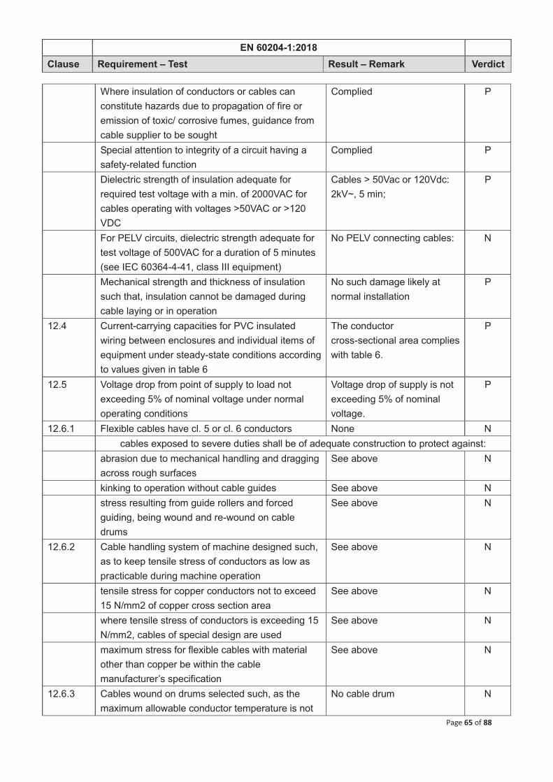
EN 60204-1:2018
Clause Requirement – Test Result – Remark Verdict
Page 65 of 88
Where insulation of conductors or cables can constitute hazards due to propagation of fire or emission of toxic/ corrosive fumes, guidance from cable supplier to be sought
Complied P
Special attention to integrity of a circuit having a safety-related function
Complied P
Dielectric strength of insulation adequate for required test voltage with a min. of 2000VAC for cables operating with voltages >50VAC or >120 VDC
Cables > 50Vac or 120Vdc: 2kV~, 5 min;
P
For PELV circuits, dielectric strength adequate for test voltage of 500VAC for a duration of 5 minutes (see IEC 60364-4-41, class III equipment)
No PELV connecting cables: N
Mechanical strength and thickness of insulation such that, insulation cannot be damaged during cable laying or in operation
No such damage likely at normal installation
P
12.4 Current-carrying capacities for PVC insulated wiring between enclosures and individual items of equipment under steady-state conditions according to values given in table 6
The conductor cross-sectional area complies with table 6.
P
12.5 Voltage drop from point of supply to load not exceeding 5% of nominal voltage under normal operating conditions
Voltage drop of supply is not exceeding 5% of nominal voltage.
P
12.6.1 Flexible cables have cl. 5 or cl. 6 conductors None N cables exposed to severe duties shall be of adequate construction to protect against: abrasion due to mechanical handling and dragging
across rough surfaces See above N
kinking to operation without cable guides See above N stress resulting from guide rollers and forced
guiding, being wound and re-wound on cable drums
See above N
12.6.2 Cable handling system of machine designed such, as to keep tensile stress of conductors as low as practicable during machine operation
See above N
tensile stress for copper conductors not to exceed 15 N/mm2 of copper cross section area
See above N
where tensile stress of conductors is exceeding 15 N/mm2, cables of special design are used
See above N
maximum stress for flexible cables with material other than copper be within the cable manufacturer’s specification
See above N
12.6.3 Cables wound on drums selected such, as the maximum allowable conductor temperature is not
No cable drum N

EN 60204-1:2018
Clause Requirement – Test Result – Remark Verdict
Page 66 of 88
exceeded
cables for circular cross-section area, installed on drums, max. current-currying capacity in free air as declared acc. to table 7
See above N
12.7.1 Conductor wires, conductor bars and slip-ring assemblies: They shall be installed or enclosed in such way, that during normal access to the machine,
protection against direct contact is achieved by application by one of the following protective measures:
- protection by partial insulation of live parts, or where this is not practicable;
No collector wires, collector bars and slip-ring assemblies
N
- protection by enclosure or barriers provide a degree of protection of at least IP2X
Motor terminal box P
Horizontal top surfaces of barriers or enclosures which are readily accessible provide a degree of protection of at least IP4X
See above N
If required degree of protection is not achieved, protection by placing live parts out of reach in combination with emergency switching-off acc. to cl. 9.2.5.4.3 applied
See above N
Conductor wires and conductor bars placed and/or protected so as to: - prevent contact, especially for unprotected
conductor wires and conductor bars, with conductive items such as the cords of pull-cord switches, strain-relief devices and drive chains;
See above N
- prevent damage from a swinging load See above N 12.7.2 Where conductor wires and conductor bars and
slip-ring assemblies are installed as part of the PE-circuit, they do not carry current in normal operation
Complied P
12.7.3 Protective conductors of current collectors have a shape or are designed such, so that they are not interchangeable with other current collectors of the sliding contact type
Complied P
12.7.4 Removable current collectors with disconnector function are designed such, that PE-circuit is interrupted only after live conductors have been disconnected and the continuity of the PE-circuit is re-established before any live conductor is reconnected (see also 8.2.4)
See above N
12.7.5 Clearances between respective conductors and between adjacent systems of conductor wires, conductor bars, slip-ring assemblies and their
Complied P

EN 60204-1:2018
Clause Requirement – Test Result – Remark Verdict
Page 67 of 88
current collectors designed for for at least a rated impulse voltage of an overvoltage category III in accordance with IEC 60664-1
12.7.6 Creepage distances suitable for operation in the intended environment, for example open air (IEC 60664-1), inside buildings, protected by enclosures
Complied P
In abnormally dusty, moist or corrosive environments, following creepage distances apply: - for unprotected conductor wires, bars and
slip-ring assemblies equipped with insulators, the minimum creepage distance is 60 mm
See above N
- for enclosed conductor wires, insulated multipole conductor bars and insulated individual conductor bars, the minimum creepage distance is 30 mm
Complied P
Gradual reduction of insulation values due to unfavourable ambient conditions regarded
See above N
12.7.7 Suitable design measures taken, in order to prevent energisation of adjacent sections by current collectors themselves
Complied P
12.7.8 conductor wires, conductor bar systems and slip-ring assemblies used for power circuits kept separately from those used for control circuit applications
See above N
above systems capable of withstanding without damage to mechanical forces and thermal effects of short circuit currents
See above N
removable covers to above systems, laid underground or under floor, designed that they cannot be opened by one person without the use of a tool
See above N
Conductor bars which are installed in a common metal enclosure, the individual section of it bonded together and connected to a protective bonding conductor at several points depending upon their length
See above N
Metal covers of conductor bars laid underground or underfloor, bonded together and connected to a protective bonding conductor
See above N
The protective bonding circuit to include the covers or cover plates of metal enclosures or underfloor ducts. Where metal hinges form a part of the bonding circuit, their continuity be verified (see Clause 18).
See above N
Underground and under floor conductor bar ducts See above N

EN 60204-1:2018
Clause Requirement – Test Result – Remark Verdict
Page 68 of 88
have drainage facilities 13 WIRING PRACTICES − 13.1.1 All connections, especially those of the protective
bonding circuit, secured against accidental loosening
Complied P
Means of connection suitable for cross-sectional areas and nature of conductors being terminated
The incoming supply conductors (L1,L2, L3) and protective conductor terminated at the terminals in the motor terminal box.
P
Connection of two or more conductors to one terminal only where terminal is designed for that purpose
None N
Only one PE-conductor connected to one terminal connecting point
Complied P
Soldered connections only, where terminals are provided which are suitable for soldering connections
None N
Terminals on terminal blocks plainly identified to correspond with markings on wiring diagrams
Complied P
Where an incorrect electrical connection (for example, arising from replacement of devices) can be a source of risk and it is not practicable to reduce the possibility of incorrect connection by design measures, the conductors and/or terminations be identified in accordance with 13.2.1.
Complied P
Installation of flexible conduits and cables such, that liquids are drained away from fittings and joints
No liquids drained likely from the fittings
N
Means to retain stranded conductors together when terminating conductors at terminals/ devices provided
By tubing P
Solder not used for that purpose Complied P Shielded conductors terminated so, as to prevent
fraying of strands and to permit easy disconnection None N
Identification tags legible, permanent and appropriate for physical environment
Complied P
Terminal blocks mounted and wired so, that internal and external wiring does not cross over terminals
Complied P
13.1.2 Conductors and cables runned from terminal to terminal without splices or joints
Complied P
Connections using plug/socket combinations with suitable protection against accidental
None N

EN 60204-1:2018
Clause Requirement – Test Result – Remark Verdict
Page 69 of 88
disconnection are not considered to be joints for the purpose of this Subclause.
Exception: Where it is impracticable to provide terminals in a junction box (for example on mobile machines, on machines having long flexible cables; cable connections exceeding a length which is not practical to be supplied by the cable manufacturer on one cable drum; repair of cable due to mechanical stresses during installation and operation), splices or joints may be used
Terminals in the terminal box N
Where it is necessary to connect or disconnect cables, sufficient extra length provided for that purpose
Complied N
Terminations of cables adequately supported to prevent mechanical stress at termination points of conductors
Complied P
Protective conductor (PE) placed close to associated conductors in order to decrease loop impedance
Complied P
13.1.3 Conductors of different circuits laid side by side and occupy the same duct or be in same multiconductor cable, provided that such arrangement does not impair proper functioning of respective circuits
Complied P
Where circuits operate at different voltage levels, conductors separated by suitable barriers or insulated for maximum voltage to which any conductor within the same duct is subjected, for example line to line voltage for unearthed systems and phase to earth voltage for earthed systems
Single voltage level N
13.1.4 Connection between pick-up and pick-up converter of an inductive power supply system The cable between the pick-up and the pick-up converter as specified by the manufacturer of
the inductive power supply shall be: – as short as practicable; None N – adequately protected against mechanical
damage. See above N
13.2 Identification of conductors: 13.2.1 Conductors identifiable at each termination point
acc. to technical documentation Conductors are identified by tags at each termination in accordance with the electrical schematic.
P
Identification of conductors by number, alphanumeric, colour (either solid or with one or
Colour is used throughout the length of the conductor.
P

EN 60204-1:2018
Clause Requirement – Test Result – Remark Verdict
Page 70 of 88
more stripes), or a combination of colour and numbers or alphanumeric
When numbers are used, they are Arabic; letters are Roman (either upper or lower case).
Complied P
13.2.2 Protective conductor readily distinguishable by shape, location, marking or colour
Protective conductor is distinguished by colouring, numbering and symbol.
P
Bicolour combination GREEN- AND- YELLOW used throughout the length of the conductor
Complied P
This colour identification is strictly reserved for the protective conductor, so that it can be easily identified by its shape
Complied P
Ends or accessible positions of a protective conductor clearly identified by graphical symbol IEC 60417-5019 (DB:2002-10) or by bicolour combination GREEN- AND- YELLOW
Bicolour combination green-and-yellow
P
13.2.3 Where a circuit includes a neutral conductor that is identified by colour alone, the colour used for this conductor is BLUE. In order to avoid confusion with other colours, it is recommended that an unsaturated blue be used, called here “light blue” (see 3.2.2 of IEC 60446).
None N
Where the selected colour is the sole identification of the neutral conductor, that colour not be used for identifying any other conductor where confusion is possible
See above N
Where bare conductors are used as neutral conductors and identification by colour is used, they either be coloured by a stripe, 15 to 100 mm wide in each compartment or unit, or at each accessible position or coloured throughout their length
See above N
13.2.4 Identification by colour − Where colour-coding is used for identification of
conductors (other than the protective conductor (see 13.2.2) and the neutral conductor (see 13.2.3)), the following colours may be used: BLACK, BROWN, RED, ORANGE, YELLOW, GREEN, BLUE (including LIGHT BLUE), VIOLET, GREY, WHITE, PINK, TURQUOISE.
Complied P
If colour coding of conductors applies, conductors coded over its full length, either by colouring of insulation or coloured markers at regular intervals
Complied P

EN 60204-1:2018
Clause Requirement – Test Result – Remark Verdict
Page 71 of 88
and at the ends or accessible location.
For safety reasons, colour GREEN or colour YELLOW not used where there is a possibility or confusion with the bicolour combination: GREEN – AND - YELLOW
Complied P
GREEN or YELLOW as a single code must not be used, except in bicolour combination GREEN-AND-YELLOW
Complied P
Where colour-coding is used for identification of conductors, it is recommended that they be colour-coded as follows:
– BLACK: a.c. and d.c. power circuits; Complied P – RED: a.c. control circuits; None N – BLUE: d.c. control circuits; None N – ORANGE: excepted circuits in accordance with
5.3.5. None N
Exceptions: to the above are permitted where: – insulation is used that is not available in the
colours recommended; or See above N
– multiconductor cable is used, but not the bicolour combination GREEN-AND-YELLOW.
None N
13.3 Conductors inside enclosures supported where necessary to keep it in place
Complied P
Non-metallic ducts permitted only when they are of flame-retardant insulating material (see the IEC 60332 series)
None N
Electrical equipment mounted inside cabinets, designed to permit modification of wiring from front of cabinet (see cl. 11.2.1)
None N
Where that is not possible, access doors or swingout panels provided
None N
Connections to devices mounted on doors or to other movable parts made with flexible conductors (acc. to cl.12.2 and 12.6) to allow for frequent movement of those parts
None N
Conductors be anchored to the fixed part and the movable part, independently of the electrical connection (see also 8.2.3 and 11.2.1)
None N
Conductors and cables that do not run in ducts are adequately supported
None N
Terminal blocks or plug /socket combinations used for control wiring, that extends beyond the enclosure
None N

EN 60204-1:2018
Clause Requirement – Test Result – Remark Verdict
Page 72 of 88
Power cables and cables for measuring-circuits are directly connected to terminals of field located devices
None N
13.4 Wiring outside enclosures: 13.4.1 Introduction of cables- or ducts by means of
individual glands, bushings etc. into an enclosure must not reduce degree of protection of it (see 11.3)
See manual P
13.4.2 Conductors and their connections outside of the enclosure, are enclosed in suitable ducts as described in cl. 13.5
See above P
Where devices such as position switches or proximity switches are supplied with a dedicated cable, their cable need not be enclosed in a duct when the cable is suitable for the purpose, sufficiently short, and so located or protected, that the risk of damage is minimized.
N
Fittings used with ducts or multiconductor cables are suitable for the physical environment
N
Flexible conduit or flexible multiconductor cable is used for flexible connections to pendant push-button stations
No pendant control N
Weight of pendant stations is supported by other means than flexible conduits or flexible multicore cables
See above N
13.4.3 Connections to frequently moving elements of the machine, designed acc. to cl. 12.2 and 12.6
None N
Flexible cables and conduits installed so, as to avoid excessive flexing and straining, particularly at the fittings
See above N
Cables exposed to movement supported in such way, as to prevent mechanical strain at connecting points
See above N
If this is achieved by provision of a loop, it has sufficient length to provide for a bending radius of at least 10 times the diameter of the cable
See above N
Flexible cables of machines installed or protected in such way, as to minimise the possibility of external damage due to factors, that include the following cable use or potential abuse:
– being runned over by the machine itself See above N – being runned over by vehicles or other machines See above N – coming into contact with the machine structure
during movements See above N
– running in and out of cable baskets or, on / off See above N

EN 60204-1:2018
Clause Requirement – Test Result – Remark Verdict
Page 73 of 88
cable drums – acceleration and wind forces on festoon systems
or suspended cables See above N
– excessive rubbing by cable collector See above N – exposure to excessive radiated heat See above N Cable sheath resistant to normal wear expected
from normal movement and effects of atmospheric contaminants
See above N
Where cables are close to moving parts, space of at least 25mm maintained between moving parts and cables
See above N
Where that distance is not practicable, fixed barriers provided between cables and moving parts
See above N
Cable handling system designed such, that lateral cable angle does not exceed 5°, avoiding torsion at the cable when
– being wound on and off the cable drums and See above N – approaching and leaving cable guidance’s See above N Measures taken to ensure that at least two turns of
cable remain on the drum See above N
Cable guides designed such, that the inner bending radius is not less than values given in table 8
See above N
Straight section between two bends at least 20 times the cable diameter
See above N
Construction and supporting means prevent damage to flexible cable under all operating conditions
See above N
No flexible conduit used for connections subject to rapid or frequent movements except when specifically designed for that purpose.
See above N
13.4.4 In case where several sensors or control elements are connected in series, it is recommended to connect them via intermediate terminals
None N
Intermediate terminals are adequately protected See above N Intermediate terminals are indicated on the wiring
diagram See above N
This enables easy access for testing purposes See above N 13.4.5 Where plug/socket combinations are provided, they fulfill one or more of the following
requirements as applicable: Exception: Components or devices inside an
enclosure, terminated by fixed plug/socket combinations (no flexible cable), or components connected to a bus system by a plug/socket
None N

EN 60204-1:2018
Clause Requirement – Test Result – Remark Verdict
Page 74 of 88
combination.
a) When installed correctly in accordance with f), plug/socket combinations of such type and installed in such way, as to prevent unintentional contact with live parts at any time , including during insertion or removal of the connectors
See above N
Min. degree of protection: IPXXB. See above N PELV circuits are excepted from this requirement See above N b) Have a first make last break protective bonding
contact (earthing contact) (see also 6.3, 8.2.4) if used in TN- or TT-systems.
See above N
c) Plug/socket combinations intended to be connected or disconnected during load conditions have sufficient load-breaking capacity.
See above N
Plug/socket combinations rated at 30 A, or greater, are interlocked with a switching device so that the connection and disconnection is possible only when the switching device is in the OFF position.
See above N
d) Plug/socket combinations rated at more than 16 A have a retaining means to prevent unintended or accidental disconnection.
See above N
e) Where an unintended or accidental disconnection of plug/socket combinations can cause a hazardous situation, they have a retaining means.
See above N
The installation of plug/socket combinations fulfill the following requirements as applicable: f) Min. degree of protection for the component
which remains live after disconnection (except for PELV circuits): IP2X or IPXXB, taking into account the required clearance and creepage distances
See above N
g) Metallic housings of plug/socket combinations connected to the protective bonding circuit (except for PELV circuits)
See above N
h) Plug/socket combinations intended to carry power loads but not to be disconnected during load conditions have a retaining means to prevent unintended or accidental disconnection and are clearly marked that they are not intended to be disconnected under load.
See above N
i) Where more than one plug/socket combination is provided in the same electrical equipment, the associated combinations are clearly identifiable. It
See above N

EN 60204-1:2018
Clause Requirement – Test Result – Remark Verdict
Page 75 of 88
is recommended that mechanical coding be used to prevent incorrect insertion.
j) Plug/socket combinations used in control circuits fulfil the applicable requirements of IEC 61984. Exception: see item k).
See above N
k) No plug/socket combinations intended for household and similar general purposes used for control circuits.
See above N
In plug/socket combinations in accordance with IEC 60309-1, only those contacts are used for control circuits which are intended for those purposes.
See above N
Exception: The requirements of item k) do not apply to control functions using high frequency signals on the power supply.
See above N
13.4.6 If wiring needs to be disconnected for shipment, terminals or plug/socket combinations are provided at the disconnecting points
See above N
13.4.7 Additional wiring for maintenance or repair purposes provided
See above N
13.5 Ducts, connection boxes and other boxes: 13.5.1 Ducts provide a degree of protection suitable for
the application (see IEC 60529) None N
All sharp edges, flash, burrs, rough surfaces or threads which the insulation of conductors can come into contact, removed from ducts and conduits
See above N
In order to avoid confusion between conduits for electrical installation and those for oil, water or air, either physically separated or suitably identified
See above N
Ducts or cable trays rigidly supported and positioned at sufficient distance from moving parts
See above N
Ducts or cable trays mounted at least 2 meters above the working surface in areas where human passage is required
See above N
Ducts provided only for mechanical protection (see cl. 8.2.3)
See above N
Cable trays which are partially covered, not to serve as cable trays or installation trunking
See above N
Conductors and cables suitable for installation with or without the use of open cable trays or cable support means
See above N

EN 60204-1:2018
Clause Requirement – Test Result – Remark Verdict
Page 76 of 88
13.5.2 Cable trays dimensioned or located such, as to enable easy access for installation of additional conductors and cables
See above N
Consideration given on percentage of filling of such ducts.
See above N
13.5.3 Rigid metal conduits or trays consist of galvanised steel or corrosion-resistant material, suitable for the environmental conditions.
See above N
Application of cable trays of different metal avoided, due to electrolytic corrosion
See above N
Installation conduits secured, held in place and supported at each end
See above N
Joints and fittings compatible with conduits and appropriate for its application
See above N
Conduit-bends fabricated such, as to avoid damage or reduction of internal cross-section
See above N
13.5.4 Flexible metallic conduits and fittings consist of flexible metal tubing or wire mesh armour.
See above N
They are suitable for its application and environmental conditions
See above N
13.5.5 Flexible non-metallic conduits are resistant to buckling and with similar characteristics as the sheath of multicore cables
See above N
They shall be suitable for its application and environmental conditions
See above N
Joints and fittings compatible with conduits and appropriate for its application
See above N
13.5.6 Cable trunking systems outside of enclosures are rigidly supported and kept clear of moving and contaminating parts of the machine
See above N
Covers shaped to overlap the sides; gaskets permitted
See above N
Covers attached to cable trunking systems by suitable means
See above N
On horizontal cable trunking systems, no cover on the bottom unless specifically designed for such installation
See above N
Where the cable trunking system is furnished in sections, the joints between sections fit tightly but need not be gasketed.
See above N
The only openings permitted are those required for wiring or for drainage
See above N
Cable trunking systems not to have opened but See above N

EN 60204-1:2018
Clause Requirement – Test Result – Remark Verdict
Page 77 of 88
unused knockouts 13.5.7 Installation of cables layed in cable trays with
covers permitted within the machine-foundations, providing that they are completely closed and separated from coolant and lubrication systems (see cl. 13.5.6)
See above N
13.5.8 Cable connection boxes and junction boxes used for wiring purposes are accessible for maintenance (see cl. 11.3)
See above N
They provide protection against ingress of solids or liquids, taking into account external influences during operation of the machine (see cl. 11.3)
See above N
Junction boxes not have openings for cable entries and are designed so, as to avoid ingress of entrained dust, lubricants and coolant
See above N
13.5.9 Motor terminal boxes used for motor cable connection and for devices attached to the motor
P
14 ELECTRIC MOTORS AND ASSOCIATED EQUIPMENT P 14.1 Electric motors are conform to EN 60034 series In according to EN60034-1 P Electric motors and associated equipment protected against following risks: overcurrent (see cl. 7.2) See manual P thermal overload (see cl. 7.3) See manual P overspeed (see cl. 7.6) N Compliance ensured with the requirements stated
(see clauses 5.3, 5.4, 5.5, 7.5, 7.6 and 9.4) P
Motor control equipment located and mounted acc. to cl. 11
No control N
14.2 Selection of motor enclosure recommended acc. to EN 60034-5
P
Degree of protection at least IP23 IP 55 P Incorporated motors mounted such, as to provide
adequate protection against mechanical damage Complied P
14.3 Dimensions of motors conform to those given in EN 60072 series
Complied P
14.4 Each motor with associated coupling, belt, pulley or chain mounted such, as to provide adequate protection and easy access for inspection, maintenance, adjustment or alignment, lubrication and replacement
Complied P
Motors mounted such, as to allow easy access to all terminal boxes
Complied P
Motors mounted such, as to ensure proper cooling Complied P

EN 60204-1:2018
Clause Requirement – Test Result – Remark Verdict
Page 78 of 88
Temperature rise to be within limits of relevant insulation class
Temperature rise within limits of relevant insulation class
Complied P
If possible, motor compartments stay clean and dry and when required, ventilated directly to the outside of the machine
Intended to be installed in an spacious area
N
Motor-vents at an acceptable level and designed such, as to avoid ingress of swarf, dust or water spray
None N
No opening between motor compartment and any other compartment, which does not fulfil the requirement for motor compartments
Complied P
14.5 Electric motors selected acc. to service and environmental conditions
Complied P
Design criteria for evaluation include: – type of motor See above P – type of duty cycle (see IEC 60034-1) Continues operation P – fixed speed or variable speed operation Fixed speed P – mechanical vibrations Considered P – type of motor control No control N – influence of the harmonic spectrum of voltage
and/or current when supplied from static converter on the temperature rise
Complied P
– method of starting and possible influence of inrush current
Complied P
– variation of counter torque load with time and speed
Complied P
– influence of loads with large inertia Complied P – influence of constant torque or constant power
operation Complied P
– possible need of inductive reactors between motor and converter
Complied P
14.6 Operation of overload or overcurrent protective devices for mechanical brake-actuators initiate simultaneous de-energisation(release) of associated machine actuators
No mechanical brake. N
15 ACCESSORIES AND LIGHTING P 15.1 Where the machine or its associated equipment is provided with socket-outlets for
auxiliary equipment, the following will apply:
socket-outlets are conform to regulations None N if not possible, they are clearly marked with voltage See above N

EN 60204-1:2018
Clause Requirement – Test Result – Remark Verdict
Page 79 of 88
and current ratings continuity of protective bonding circuit to be
ensured except where protection is provided by PELV
See above N
all unearthed conductors connected to socket-outlets, protected against overcurrent
See above N
when required, protection against overload in accordance with cl. 7.2 and cl. 7.3 separately from protection of other circuits
See above N
if power supply to socket-outlets is not disconnected, than requirements of cl.5.3.5 apply
See above N
15.2 Local lighting of the machine and equipment 15.2.1 Connection to PE-circuit acc. to cl. 8.2.2 No local lighting N ON-OFF switch not incorporated in lampholder or
in flexible connecting cord See above N
Stroboscopic effects from lights avoided See above N If fixed lighting is provided in an enclosure,
electromagnetic compatibility (EMC) taken into account
See above N
Application of EMC requirements acc. to principles stated in cl. 4.4.2
See above N
15.2.2 If higher voltages are applied, value not exceeding 250 V between conductors
See above N
Nominal voltage of local lighting circuits not exceeding 50 V
See above N
Lighting circuits supplied from one of the following sources: – from a dedicated isolating transformer connected
to load side or See above N
– overcurrent protection provided in secondary circuit or
See above N
– a dedicated isolating transformer connected to line side provided or (see also 5.3.5 and 13.1.3)
See above N
– source permitted for maintenance purpose or See above N – lighting circuits placed in control enclosures only
or See above N
– overcurrent protection provided in secondary circuit or
See above N
– from a machine-circuit with dedicated overcurrent protection or
See above N
– from an isolating transformer connected to line side of supply disconnecting device, when a dedicated primary disconnecting means and a
See above N

EN 60204-1:2018
Clause Requirement – Test Result – Remark Verdict
Page 80 of 88
secondary overcurrent protection are provided or
– for an externally supplied lighting circuit, which is only permitted in a control enclosures
See above N
Exception: Where fixed lighting is out of reach for operator during normal operations, provisions of this subclause do not apply
See above N
15.2.3 local lighting circuits protected See above N 15.2.4 adjustable lighting fittings suitable for the physical
environment provided See above N
lampholders in accordance with relevant IEC-publications and
See above N
designed of an insulating material protecting the lamp cap, as to prevent unintentional contact
See above N
reflectors supported by a bracket and not by the lampholder
See above N
Exception: Where fixed lighting is out of reach for operator during normal operations, provisions of this subclause do not apply
See above N
16 MARKING, WARNING SIGNS AND REFERENCE DESIGNATIONS 16.1 Warning signs, nameplates, markings- and
identification plates of sufficient durability to withstand the physical environment involved
Complied P
16.2 Warning signs 16.2.1 Electric shock hazard Enclosures that do not otherwise clearly show that
they contain electrical equipment that can give rise to a risk of electric shock, are marked with the graphical symbol IEC 60417-5036 (DB:2002-10)
On the terminal box P
Warning sign plainly visible on the enclosure, door or cover-plate
Complied P
The warning sign may be omitted for (see also 6.2.2 b)): – an enclosures equipped with a supply
disconnecting device or See above N
– an operator - machine interface or for a control-station or
See above N
– a single device with its own enclosure See above N 16.2.2 Where the risk assessment shows the need to
warn against the possibility of hazardous surface temperatures of the electrical equipment, the graphical symbol IEC 60417-5041 (DB:2002-10) is used
None N

EN 60204-1:2018
Clause Requirement – Test Result – Remark Verdict
Page 81 of 88
16.3 Control devices, visual indicators and displays (particularly those related to safety) clearly and durably marked with regard to their functions either on, or adjacent to it
None N
such markings as agreed between user and supplier
See above N
preference given to the use of standard symbols given in IEC 60417- DB:2002 and ISO 7000.
See above N
16.4 Marking of equipment Equipment (for example controlgear assemblies)
legibly and durably marked so that it is plainly visible after equipment installation
Complied P
Nameplates attached to enclosures adjacent to each incoming supply shall contain the following information:
– name or trade mark of supplier and Complied P – certification mark, when required and CE mark P – serial number, where applicable and Complied P – rated voltage and 380V P – number of phases and 3~ P – frequency (if AC) and 50 Hz P – full-load current for each supply Complied P – short-circuit interrupting capacity of overcurrent
protective device, where furnished as part of device of equipment
See installation instructions N
– main document number (see IEC 62023) N Full-load current shown on nameplate not less than
the running currents of all motors and other electrical loads, that are in operation at the same time under normal conditions
Complied P
if a single motor controller is used, that information provided instead, on the machine nameplate
No controller N
16.5 All enclosures, assemblies, control devices and components plainly identified with the same reference designation as shown in technical documentation
Complied P
17 TECHNICAL DOCUMENTATION 17.1 Information necessary for installation, operation
and maintenance of electrical equipment for a machine supplied by means of drawings, wiring diagrams, charts, tables and instruction manuals
Complied P
Information provided in an agreed language English P 17.2 Information provided with electrical equipment shall include:

EN 60204-1:2018
Clause Requirement – Test Result – Remark Verdict
Page 82 of 88
a) A main document (parts list or list of documents); P b) Complementary documents including: 1) a clear, comprehensive description of the
equipment, installation and mounting instructions and information regarding connection to the electrical supply(ies)
Complied P
2) electrical supply requirements Complied P 3) information about the physical environment Complied P 4) overview (block) diagram(s) N 5) circuit / wiring diagram(s) N 6) information about: software program documentation/ listing No software N sequence of operation(s) Complied P frequency of inspection Complied P frequency and method of functional testing Complied P guidance on the adjustment, maintenance and
repair, particularly of the protective devices and circuits
Complied P
recommended spare parts list; and Complied P list of tools supplied. N 7) description of safeguards, interlocking func tions
and interlocking of separating safeguards for dangerous movements of co-ordinated operating machines
N
8) description of safeguards and means provided for applications with to suspend the safeguards
N
9) instructions on the procedures for securing the machine for safe maintenance; (see also 17.8);
Complied P
10) information on handling, transportation and storage;
Complied P
11) information regarding load currents, peak starting currents and permitted voltage drops, as applicable;
Complied P
12) information on the residual risks due to the protection measures adopted, indication of whether any particular training is required and specification of any necessary personal protective equipment.
N
17.3 Requirements applicable to all documentation Unless otherwise agreed between manufacturer and user: – documentation to be in accordance with relevant
parts of IEC 61082 Complied P
– reference designation system to be in Complied P

EN 60204-1:2018
Clause Requirement – Test Result – Remark Verdict
Page 83 of 88
accordance with relevant parts of IEC 61346 – instructions/manuals to be in accordance with
IEC 62079. Complied P
– parts lists where provided to be in accordance with IEC 62027, class B.
Complied P
For referencing to different documents, the supplier has to select one of following methods: – where the documentation consists of a small
number of documents (for example less than 5), each of the documents carry a cross-reference with document numbers of all other documents belonging to the electrical equipment or
N
– for single level main documents only (see IEC 62023), all documents to be listed with document numbers and titles in a drawing or document list
N
– all documents of a certain level (see IEC 62023) of the document structure shall be listed, with document numbers and titles, in a parts list belonging to the same level.
N
17.4 The installation diagram provides all necessary information regarding preliminary work for the setting-up of the machine (including commissioning)
Complied P
In complex cases, it is necessary to refer to the assembly drawings for details
Complied P
Recommended routing, type and cross-sectional areas for the conductors of the supply cables installed on site clearly indicated
Complied P
Necessary data or choosing type, characteristics, rated currents and setting for the overcurrent protective devices for the supply conductors stated (see cl. 7.2.2)
Complied P
Detailed information provided about size, purpose and location of any cable ducts within the foundation, that are provided by the user
Complied P
Detailed information provided about size, type and purpose of cable ducts, trays or supports between machine and associated equipment
Complied P
Diagram to indicate where space is required for removal or servicing of electrical equipment
Complied P
Where appropriate, an interconnection diagram or table provided
Complied P
17.5 Where necessary an overview diagram provided for explanation of the principle of operation
N

EN 60204-1:2018
Clause Requirement – Test Result – Remark Verdict
Page 84 of 88
Overview diagram symbolically represents the electrical equipment with its functional interrelationships without showing all the interconnections
N
The function diagram used as either part of or addition to the block diagram
N
17.6 Circuit diagrams show the electrical circuits on the machine and its associated electrical equipment
N
Any graphical symbol not shown in IEC 60617-DB:2001 must be separately shown and described on the wiring diagrams or supporting documents
N
The symbols and identification of components consistent throughout all documents and on the machine
N
Where appropriate, a diagram provided, showing the interface terminals and connections
N
The diagram shows a reference to the detailed circuit diagram of each unit
N
Switch symbols shown on the circuit diagrams with all supplies turned off and with the machine and its electrical equipment ready for a normal start
N
Conductors identified acc. to cl.13.2 N Characteristics relating to the function of the control
device and components which are not evident from their symbolic representation, included on the diagrams adjacent to the symbol or referenced to a footnote
N
17.7 Technical documentation containing an operating manual, outlining proper procedures for set-up and use of electrical equipment
Complied P
Particular attention given to safety measures provided
Complied P
Detailed information provided on methods for equipment programming, program verification and additional safety procedures
Complied P
17.8 Technical documentation to contain a maintenance manual, detailing proper procedures for adjustment, servicing or preventive inspection and repair
Complied P
Recommendations regarding maintenance or service intervals and records are part of it
Complied P
Methods for the verification of proper operation provided
Complied P
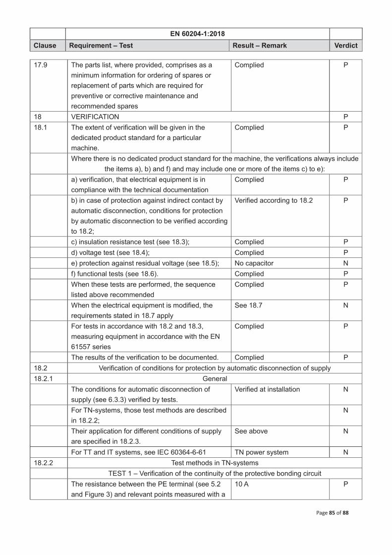
EN 60204-1:2018
Clause Requirement – Test Result – Remark Verdict
Page 85 of 88
17.9 The parts list, where provided, comprises as a minimum information for ordering of spares or replacement of parts which are required for preventive or corrective maintenance and recommended spares
Complied P
18 VERIFICATION P 18.1 The extent of verification will be given in the
dedicated product standard for a particular machine.
Complied P
Where there is no dedicated product standard for the machine, the verifications always include the items a), b) and f) and may include one or more of the items c) to e):
a) verification, that electrical equipment is in compliance with the technical documentation
Complied P
b) in case of protection against indirect contact by automatic disconnection, conditions for protection by automatic disconnection to be verified according to 18.2;
Verified according to 18.2 P
c) insulation resistance test (see 18.3); Complied P d) voltage test (see 18.4); Complied P e) protection against residual voltage (see 18.5); No capacitor N f) functional tests (see 18.6). Complied P When these tests are performed, the sequence
listed above recommended Complied P
When the electrical equipment is modified, the requirements stated in 18.7 apply
See 18.7 N
For tests in accordance with 18.2 and 18.3, measuring equipment in accordance with the EN 61557 series
Complied P
The results of the verification to be documented. Complied P 18.2 Verification of conditions for protection by automatic disconnection of supply 18.2.1 General The conditions for automatic disconnection of
supply (see 6.3.3) verified by tests. Verified at installation N
For TN-systems, those test methods are described in 18.2.2;
N
Their application for different conditions of supply are specified in 18.2.3.
See above N
For TT and IT systems, see IEC 60364-6-61 TN power system N 18.2.2 Test methods in TN-systems TEST 1 – Verification of the continuity of the protective bonding circuit The resistance between the PE terminal (see 5.2
and Figure 3) and relevant points measured with a 10 A P

EN 60204-1:2018
Clause Requirement – Test Result – Remark Verdict
Page 86 of 88
current 0,2 A to 10 A
No use of a PELV supply recommended since such supplies can produce misleading results in this test.
No PELV N
The resistance measured to be in the expected range according to the length, the cross sectional area, and the material of the related protective bonding conductor(s)
(see Appendix C.1) P
TEST 2 – Fault loop impedance verification and suitability of the associated overcurrent protective device
Connections of power supply and of incoming external protective conductor to the PE terminal of the machine verified by inspection
This machine is supplied to site whole and whose cables do not exceed certain lengths which are at least 28m.
N
Conditions for the protection by automatic disconnection of supply in accordance with 6.3.3 and Annex A verified by both:
1) verification of the fault loop impedance by: – calculation, or See above N – measurement in accordance with A.4, and See above N 2) confirmation that the setting and characteristics
of the associated overcurrent protective device are in accordance with the requirements of Annex A
See above N
18.2.3 Application of the test methods for TN-systems Test 1 of 18.2.2 carried out on each protective
bonding circuit of a machine See above N
When Test 2 of 18.2.2 is carried out by measure-ment, it is always to be preceded by Test 1.
See above N
The tests that are necessary for machines of different status are specified in Table 9.
See above N
Table 10 can be used to enable determination of the machine status.
See above N
18.3 Insulation resistance measured with 500VDC between power circuit conductors and protective bonding circuit is to be ≥ 1.0 MΩ
Complied P
Test made on individual sections of complete electrical installation
Test in complete electrical installation.
P
For certain parts of the electrical equipment, a lower minimum insulation value is permitted, but not less than 50 kΩ
>> 1.0 MΩ P
If the electrical equipment of the machine contains surge protection devices which are likely to operate during the test, it is permitted to either:
– disconnect these devices, or None N

EN 60204-1:2018
Clause Requirement – Test Result – Remark Verdict
Page 87 of 88
– reduce the test voltage to a value lower than the voltage protection level of the surge protection devices, but not lower than the peak value of the upper limit of the supply (phase to neutral) voltage.
See above N
18.4 When voltage tests are performed, test equipment in accordance with IEC 61180-2
Complied P
Test voltage at a nominal frequency of 50Hz or 60Hz,
60Hz P
Maximum test voltage at a value of twice the rated supply voltage of the equipment or 1000 VAC (or 1414 VDC), whichever is the greater
1000 VAC P
Maximum test voltage applied between the power circuit conductors and the protective bonding circuit for a period of approximately 1 s.
Complied P
Requirements are satisfied if no disruptive discharge occurs.
Complied P
Components not rated to withstand these test voltage are disconnected during testing
Complied P
Components and devices that have been voltage tested in accordance with their product standards are disconnected during testing.
None N
18.5 Tests for protection against residual voltages are performed to ensure compliance with cl. 6.2.4
No capacitor N
18.6 Function tests of the electrical equipment performed, particularly those related to function of circuits for electrical safety (for example earth fault detection)
Power on/off test P
18.7 Where a portion of the machine and its associated equipment is changed or modified, that portion is reverified and retested as appropriate (see cl. 18.1)
Brand new product N

Page 88 of 88
Photos
* THE END *

Page 1 of 17
TABLE OF CONTENTS
GENERAL INFORMATION................................................................................................................... 3 PRODUCT DESCRIPTION FOR EQUIPMENT UNDER TEST (EUT)............................................................................................................................. 3 OBJECTIVE .................................................................................................................................................................................................................. 3 EQUIPMENT MODIFICATIONS.................................................................................................................................................................................... 3
1 - EN61000-6-3.......................................................................................................................................... 4 1.1 CONTINUOUS DISTURBANCE VOLTAGE AT MAINS TERMINAL......................................................................................................................... 4 1.1.1 TEST EQUIPMENT LIST AND DETAILS.............................................................................................................................................................. 4 1.1.2 DESCRIPTION OF MEASUREMENT CONDITIONS.............................................................................................................................................. 4 1.1.3 LIMITS OF CONTINUOUS DISTURBANCE VOLTAGE AT MAINS TERMINAL. .................................................................................................. 4 1.1.4 CONFIGURATION................................................................................................................................................................................................ 5 1.1.5 VERDICT ............................................................................................................................................................................................................. 5 1.2 RADIATED DISTURBANCES ................................................................................................................................................................................... 6 1.2.1 TEST EQUIPMENT LIST AND DETAILS.............................................................................................................................................................. 6 1.2.2 DESCRIPTION OF MEASUREMENT CONDITIONS.............................................................................................................................................. 6 1.2.3 LIMITS OF RADIATED DISTURBANCES OF CLASS B ITE AT A MEASURING DISTANCE OF 10M. ................................................................... 6 1.2.4 CONFIGURATION................................................................................................................................................................................................ 6 1.2.5 TEST DATA AND RECORDS................................................................................................................................................................................ 7 1.2.6 VERDICT THE EUT MET THE REQUIREMENT. ............................................................................................................................................... 7
2 – EN61000-6-1......................................................................................................................................... 8 DESCRIPTION OF PERFORMANCE CRITERION ( ACCORDING WITH EN61000-6-2 SECTION 4 )........................................................................... 8 PERFORMANCE CRITERION A ................................................................................................................................................................................... 8 PERFORMANCE CRITERION B ................................................................................................................................................................................... 8 PERFORMANCE CRITERION C ................................................................................................................................................................................... 8 2.1 SURGES................................................................................................................................................................................................................ 9 2.1.1 TEST EQUIPMENT LIST AND DETAILS.............................................................................................................................................................. 9 2.1.2 DESCRIPTION OF MEASUREMENT CONDITIONS.............................................................................................................................................. 9 2.1.3 CONFIGURATION................................................................................................................................................................................................ 9 2.1.4 VERDICT ............................................................................................................................................................................................................. 9 2.2 ESD...................................................................................................................................................................................................................... 10 2.2.1 TEST EQUIPMENT LIST AND DETAILS............................................................................................................................................................ 10 2.2.2 DESCRIPTION OF MEASUREMENT CONDITIONS............................................................................................................................................ 10 2.2.3 CONFIGURATION.............................................................................................................................................................................................. 10 2.2.4 PERFORMANCE CRITERION ............................................................................................................................................................................ 10 2.2.5 TEST DATA AND RECORDS.............................................................................................................................................................................. 11 2.2.6 VERDICT ........................................................................................................................................................................................................... 11 2.3 EFT/B .................................................................................................................................................................................................................. 12 2.3.1 TEST EQUIPMENT LIST AND DETAILS............................................................................................................................................................ 12 2.3.2 DESCRIPTION OF MEASUREMENT CONDITIONS............................................................................................................................................ 12 2.3.3 CONFIGURATION.............................................................................................................................................................................................. 12 2.3.4 VERDICT ........................................................................................................................................................................................................... 12 2.4 INJECTED CURRENTS .................................................................................................................................................................................. 13 2.4.1 TEST EQUIPMENT LIST AND DETAILS............................................................................................................................................................ 13 2.4.2 DESCRIPTION OF MEASUREMENT CONDITIONS............................................................................................................................................ 13 2.4.3 CONFIGURATION.............................................................................................................................................................................................. 13 2.4.4 VERDICT ........................................................................................................................................................................................................... 13 2.5VOLTAGE DIPS AND INTERRUPTIONS .................................................................................................................................................... 14 2.5.1 TEST EQUIPMENT LIST AND DETAILS............................................................................................................................................................ 14 2.5.2 DESCRIPTION OF MEASUREMENT CONDITIONS............................................................................................................................................ 14 2.5.3 CONFIGURATION.............................................................................................................................................................................................. 14 2.5.4 VERDICT ........................................................................................................................................................................................................... 14 2.6 RADIO-FREQUENCY ELECTROMAGNETIC FIELD .............................................................................................................................................. 15 2.6.1 TEST EQUIPMENT LIST AND DETAILS............................................................................................................................................................ 15 2.6.2 DESCRIPTION OF MEASUREMENT CONDITIONS............................................................................................................................................ 15 2.6.3 CONFIGURATION.............................................................................................................................................................................................. 15
EN 61000-6-1:2019 EN 61000-6-3:2007+A1:2011 test report

Page 2 of 17
2.6.4 PERFORMANCE CRITERION ........................................................................................................................................................................... 15 2.6.5 TEST DATA AND RECORDS.............................................................................................................................................................................. 15 2.6.6 VERDICT ........................................................................................................................................................................................................... 15
APPENDIX A —PRODUCT PHOTOGRAPH .................................................................................... 16

Page 3 of 17
GENERAL INFORMATION
Objective In order to meet the EMC requirements approved by CENELEC, the following standards will be cited:
Note: The test data is only valid for the test sample. There is possible deviation from the original test data for other products
1.EN 61000-6-1:2019 ELECTROMAGNETIC COMPATIBILITY (EMC) - PART 6-1: GENERIC STANDARDS
2.EN 61000-6-3:2007+A1:2011 ELECTROMAGNETIC COMPATIBILITY (EMC) - PART 6-3: GENERIC
- IMMUNITY FOR RESIDENTIAL, COMMERCIAL AND LIGHT-INDUSTRIAL ENVIRONMENTS
STANDARDS - EMISSION STANDARD FOR RESIDENTIAL, COMMERCIAL AND LIGHT-INDUSTRIAL ENVIRONMENTS

Page 4 of 17
1 - EN61000-6-3 1.1 Continuous Disturbance Voltage at Mains Terminal. 1.1.1 Test Equipment List and Details
Manufacturer Description Model Serial Number
No.2 Radio factory of
Changzhou
AFJ 16A LINE Impedance
Stabilization Network
1.1.2 Description of Measurement Conditions The EUT should be compliable with the limit and methods of measurement in the standard EN61000-6-3, Electromagnetic compatibility-Generic standards- Emission standard for residential, commercial and light-industrial environments. Temperature: 21 Humidity: 58% Pressure: 1033mbar Electromagnetic environment: normal 1.1.3 Limits of Continuous Disturbance Voltage at Mains Terminal.
Limit values dB��V Equipment type Frequency range
MHz Quasi-peak Average
0.15 to 0.5 66-56 a 56- 46 a
0.5 to 5 56 46 Household appliance
5 to 30 60 50 a Decreasing linearly with logarithm of the frequency.
Note: If the limit for the measurement with the average detector is met when using a receiver with a quasi-peak detector, the equipment under test shall be deemed to meet both limits and the measurement using the receiver with an average detector need not be carried out.
Screened Room P-22 No
AFJ EMI Receiver ER55 CR/2.8 55790015165
LS16C 16010020077

Page 5 of 17
1.1.4 Configuration The configuration is in accordance with the requirement in EN61000-6-3, the sketch map as follow: 0.8m 0.8m 1.1.5 Verdict Not applicable.
EUT
AMN
EMI Receiver
Transformer
AC Power

Page 6 of 17
1.2 Radiated disturbances 1.2.1 Test Equipment List and Details
Manufacturer Description Model Serial Number
Albatross Project 3Meter Anechoic Chamber
AFJ 16A LINE Impedance
Stabilization Network
1.2.2 Description of Measurement Conditions Temperature: 20 Humidity: 60% Pressure: 1033mbar Electromagnetic environment: normal 1.2.3 Limits of radiated disturbances of class B ITE at a measuring distance of 10m.
Frequency range MHz
Quasi-peak limits(10m) dB( V/m)
30 to 230
230 to 1000
30
37 NOTE: The lower limit shall apply at the transition frequency. NOTE: Additional provisions may be required for cases where interference occurs. 1.2.4 Configuration The configuration is in accordance with the requirement in EN61000-6-3, the sketch map as follow:
SCHAFFNER CBL6112B / Receive Antenna
AFJ EMI Receiver ER55 CR/2.8 55790015165
9290832
LS16C 16010020077

Page 7 of 17
Dipole 30m h=1m~4m 0.8m Mains 1.2.5 Test Data and Records
1.2.6 Verdict The EUT met the requirement.
EUT
EMI Receiver
0 10 20 30 40 50 60
30 200 400 600 800 1000
Leve
l in
dB/m
Frequency in MHz
EMI RADIATED HL562 AUTO_Ver

Page 8 of 17
2 – EN61000-6-1 Description of Performance Criterion ( According with EN61000-6-2 Section 4 ) Performance Criterion A The apparatus shall continue to operate as intended during the test. No degradation of performance or loss of function is allowed below a performance level (or permissible loss of performance) specified by the manufacturer, when the apparatus is used as intended. If the minimum performance level or the permissible performance loss is not specified by the manufacture, then either of these may be derived from the product description and documentation, and from what the user may reasonably expect from the apparatus if used as intended. Performance Criterion B The apparatus shall continue to operate as intended after the test. No degradation of performance or loss of function is allowed below a performance level (or permissible loss of performance) specified by the manufacturer, when the apparatus is used as intended. During the test, degradation of performance is allowed, however, no change of actual operating state or stored data is allowed. If the minimum performance level or the permissible performance loss is not specified by the manufacture, then either of these may be derived from the product description and documentation, and from what the user may reasonably expect from the apparatus if used as intended. Performance Criterion C Temporary loss of function is allowed, provided the function is self-recoverable or can be restored by the operation of the controls, or by any operation specified in the instructions for use.
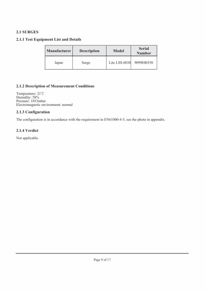
Page 9 of 17
2.1 SURGES 2.1.1 Test Equipment List and Details
Manufacturer Description Model Serial Number
2.1.2 Description of Measurement Conditions Temperature: 21 Humidity: 58% Pressure: 1033mbar Electromagnetic environment: normal 2.1.3 Configuration The configuration is in accordance with the requirement in EN61000-4-5, see the photo in appendix. 2.1.4 Verdict Not applicable.
Japan Surge Lite LSS-6030 9099E00350

Page 10 of 17
2.2 ESD 2.2.1 Test Equipment List and Details
Manufacturer Description Model Serial Number
Shanghai Sanki
Electrostatic Discharge tester
2.2.2 Description of Measurement Conditions Temperature: 21 Humidity: 58% Pressure: 1033mbar Electromagnetic environment: normal 2.2.3 Configuration The configuration is in accordance with the requirement in EN61000-4-2, see the photo in appendix. 2.2.4 Performance Criterion
Request of Pass
Air Discharge
Test Levels EN61000-4-2
Test Points -2 kV
+2 kV
-4 kV
+4 kV
-6 kV
+6 kV
-8 kV
+8 kV
-10 kV
+10 kV
-12.5 kV
+12.5 kV
-15 kV
+15 kV
-20 kV
+20 kV
EUT Front Side B B B B B B B B
EUT Top Side B B B B B B B B
EUT Back Side B B B B B B B B
EUT Left Side B B B B B B B B
EUT Right Side B B B B B B B B
ESD-320 0329501C

Page 11 of 17
Direct Contact Test Levels
EN61000-4-2 Test Points
-2 kV
+2 kV
-4 kV
+4 kV
-6 kV
+6 kV
-8 kV
+8 kV
-10 kV
+10 kV
-12.5 kV
+12.5 kV
-15 kV
+15 kV
-20 kV
+20 kV
EUT Front Side B B B B B B
EUT Top Side B B B B B B
EUT Back Side B B B B B B
EUT Left Side B B B B B B
EUT Right Side B B B B B B
2.2.5 Test Data and Records
Air Discharge Test Levels
EN61000-4-2 Test Points
-2 kV
+2 kV
-4 kV
+4 kV
-6 kV
+6 kV
-8 kV
+8 kV
-10 kV
+10 kV
-12.5 kV
+12.5 kV
-15 kV
+15 kV
-20 kV
+20 kV
EUT Front Side A A A A A A A A
EUT Top Side A A A A A A A A
EUT Back Side A A A A A A A A
EUT Left Side A A A A A A A A
EUT Right Side A A A A A A A A
Direct Contact
Test Levels EN61000-4-2
Test Points -2 kV
+2 kV
-4 kV
+4 kV
-6 kV
+6 kV
-8 kV
+8 kV
-10 kV
+10 kV
-12.5 kV
+12.5 kV
-15 kV
+15 kV
-20 kV
+20 kV
EUT Front Side A A A A A A
EUT Top Side A A A A A A
EUT Back Side A A A A A A
EUT Left Side A A A A A A
EUT Right Side A A A A A A
2.2.6 Verdict The apparatus continue to operate as intended during the test. No degradation of performance or loss of function.it is belong to Performance Criterion A .so they met the requirement.

Page 12 of 17
2.3 EFT/B 2.3.1 Test Equipment List and Details
Manufacturer Description Model Serial Number
Shanghai Sanki
2.3.2 Description of Measurement Conditions Temperature: 21 Humidity: 58% Pressure: 1033mbar Electromagnetic environment: normal 2.3.3 Configuration The configuration is in accordance with the requirement in EN61000-4-4, see the photo in appendix. 2.3.4 Verdict Not applicable.
E.F.TB Generator 8014 069504E

Page 13 of 17
2.4 INJECTED CURRENTS 2.4.1 Test Equipment List and Details
Manufacturer Description Model Serial Number
FLUKE Synthesized RF Signal Generator
QF Broadband Power Amplifier
2.4.2 Description of Measurement Conditions Temperature: 21 Humidity: 58% Pressure: 1033mbar Electromagnetic environment: normal 2.4.3 Configuration The configuration in accordance with the requirement in EN61000-4-6, see the photo in appendix. 2.4.4 Verdict Not applicable.
6061A 5080312
QF3860 No
QF Millivoltmeter QF2281 92028

Page 14 of 17
2.5VOLTAGE DIPS AND INTERRUPTIONS 2.5.1 Test Equipment List and Details
Manufacturer Description Model Serial Number
Japan Voltage Dip Simulator
2.5.2 Description of Measurement Conditions Temperature: 21 Humidity: 58% Pressure: 1033mbar Electromagnetic environment: normal 2.5.3 Configuration The configuration in accordance with the requirement in EN61000-4-11, see the photo in appendix. 2.5.4 Verdict Not applicable.
VDS-220B 2199D00098
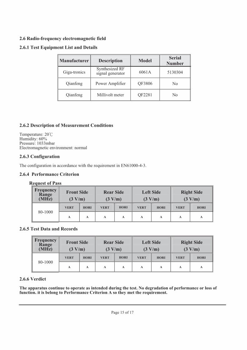
Page 15 of 17
2.6 Radio-frequency electromagnetic field 2.6.1 Test Equipment List and Details
Manufacturer Description Model Serial Number
Giga-tronics Synthesized RF signal generator 6061A 5130304
Qianfeng Power Amplifier QF3806 No
2.6.2 Description of Measurement Conditions Temperature: 20 Humidity: 60% Pressure: 1033mbar Electromagnetic environment: normal 2.6.3 Configuration The configuration in accordance with the requirement in EN61000-4-3. 2.6.4 Performance Criterion
Request of Pass Frequency
Range (MHz)
Front Side (3 V/m)
Rear Side (3 V/m)
Left Side (3 V/m)
Right Side (3 V/m)
VERT HORI VERT HORI VERT HORI VERT HORI 80-1000
A A A A A A A A
2.6.5 Test Data and Records
Frequency Range (MHz)
Front Side (3 V/m)
Rear Side (3 V/m)
Left Side (3 V/m)
Right Side (3 V/m)
VERT HORI VERT HORI VERT HORI VERT HORI 80-1000
A A A A A A A A
2.6.6 Verdict The apparatus continue to operate as intended during the test. No degradation of performance or loss of function. it is belong to Performance Criterion A so they met the requirement.
Qianfeng Millivolt meter QF2281 No

Page 16 of 17
APPENDIX A PRODUCT PHOTOGRAPH

HANGZHOU IECHO SCIENCE &TECHNOLOGY CO., LTD
NO.1 BUILDING, NO.1 WEIYE ROAD, BINJIANG DISTRICT, HANGZHOU CITY, ZHEJIANG PROVINCE, CHINA.
A2 NAMEPLATE
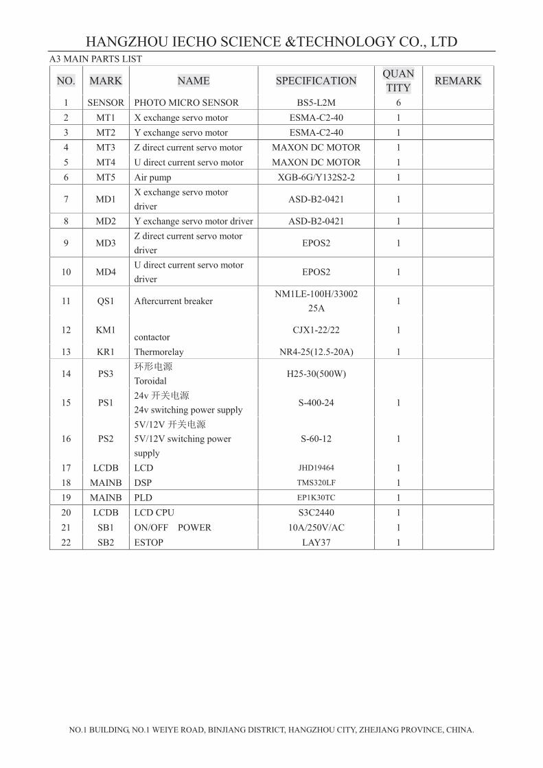
HANGZHOU IECHO SCIENCE &TECHNOLOGY CO., LTD
NO.1 BUILDING, NO.1 WEIYE ROAD, BINJIANG DISTRICT, HANGZHOU CITY, ZHEJIANG PROVINCE, CHINA.
A3 MAIN PARTS LIST
NO. MARK NAME SPECIFICATION QUANTITY REMARK
1 SENSOR PHOTO MICRO SENSOR BS5-L2M 6 2 MT1 X exchange servo motor ESMA-C2-40 1 3 MT2 Y exchange servo motor ESMA-C2-40 1 4 MT3 Z direct current servo motor MAXON DC MOTOR 1 5 MT4 U direct current servo motor MAXON DC MOTOR 1 6 MT5 Air pump XGB-6G/Y132S2-2 1
7 MD1 X exchange servo motor driver
ASD-B2-0421 1
8 MD2 Y exchange servo motor driver ASD-B2-0421 1
9 MD3 Z direct current servo motor driver
EPOS2 1
10 MD4 U direct current servo motor driver
EPOS2 1
11 QS1 Aftercurrent breaker NM1LE-100H/33002
25A 1
12 KM1 contactor
CJX1-22/22 1
13 KR1 Thermorelay NR4-25(12.5-20A) 1
14 PS3
Toroidal H25-30(500W)
15 PS1 24v 24v switching power supply
S-400-24 1
16 PS2 5V/12V 5V/12V switching power supply
S-60-12 1
17 LCDB LCD JHD19464 1 18 MAINB DSP TMS320LF 1 19 MAINB PLD EP1K30TC 1 20 LCDB LCD CPU S3C2440 1
21 SB1 ON/OFF POWER 10A/250V/AC 1
22 SB2 ESTOP LAY37 1


1
ORIGINAL INSTRUCTIONS
Digital Cutting Machine
MODEL: BK, BK2, BK3, BKL, BKM, BKMS, GLK, LCP, SC, SCT, TK,
TK3S, GLS, LCPS, PK, VK, TK4S, SK2
Manufacturer: Hangzhou IECHO Automatic Technology Co., Ltd
Building 11(C1), NO.20 Dongqiao Road, Dongzhou Subdistrict, Fuyang District, Hangzhou city, Zhejiang Province, China..

2
Directory 1. Introduction 1.1 System components 1.2 Working principle 1.3 Technical parameters
2. Safety Announcement 3. Operation 3.1 Machine key 3.2 Machine running 3.2.1 Text before running 3.2.2 SK Start 3.2.3 Preparation and debug before cutting 3.2.4 Cutting 3.2.5 Turn off machine 3.3 Daily maintenance of machine 3.3.1 The alter of cutting tools 3.3.2 Adjust knife height 3.3.3 Maintenance of machine 3.4 Parameters modification of the machine 3.4.1 Basic parameters of the machine 3.4.2 Step factor adjustment 3.4.3 Knife holder shift adjustment 3.4.4 Other parameters setting 4. Machine software 4.1 Open pattern file 4.1.1 Create Marker 4.1.2 Open CUT file 4.1.3 Import ECHO online marker (mkm file) 4.1.4 Import external data (dxf and plt files) 4.2 Save file 4.3 Marking 4.3.1 Set marking attributes 4.3.2 Marking function 4.3.3 Tool menu 4.3.4 Marking system function setting 4.4 Data edit 4.4.1 Simple edit of patters 4.4.2 Modification of external data import

3
4.5 Machine output setting 4.5.1 Configure software relative parameters according to cutter 4.5.2 Appoint pattern knife and pen cutting attribute 4.5.3 Appoint the cutting sequence of patterns 4.5.4 Appoint the pattern output line and sequence 4.5.5 Parameters debug file sending of cutter 5. Common trouble removal of machine SK software shortcut key explanation
1. Introduction
BK BK2 BK3 BKL BKM BKMS GLK LCP SC SCT TK TK3S GLS LCS cutting machine is easy to handle, it can cut carbon fiber, glass fiber, PVC, leather and other soft composites automatically with high speed, without making sampling, drawing line and cutting dies. This system can accommodate five tools simultaneously and switch quickly. With ECHO powerful automatic nesting system to reduce the space between patterns, improve the material utilization and save costs.
Cutting machine adopts advanced speed control strategies, with high speed, high accuracy, strong stability and other characteristics. It can cut a wide variety of industrial and textile fabric, to provide integrated CAD/CAM solutions to aviation, marine, automobile, inflatable, luggage& bags, garment, furniture, shoes& caps, and meet the customers' individual cutting needs
1.1System components
BK BK2 BK3 BKL BKM BKMS GLK LCP SC SCT TK TK3S GLS
LCS high precision digital cutting system composes machine body, electric box,
vacuum pump, table to pick up material, automatic material conveyor and data output
center software.
1.2Working principle
Deal with the patterns (dxf or plt formats) for outline analyzing, automatic marking,
cutting tool and types definition with SK software, the file after disposal can be
conveyed to the electric control center of the machine automatically, the control center
can finish the outline track, knife rotation angle calculation according the data, and
realize the cutting head moving and knife tangential direction rotation control with
movement controller, and finish the automatic cutting with the knife press control

4
and original position functions.
1.3Technical parameters
, , , , ,
MODEL BK
Max. cutting speed(mm/s) 1000
Cutting accuracy(mm) 0.02
Max. Cutting thickness(mm) 50
Data format DXF HPGL
Cutting width(MAX mm) 800mm-3000mm
Cutting length(MAX mm) 800mm-3000mm
Interface Network
Driver Servo motor
Media absorption Vacuum
Power 380V/50HZ
Operation environment Temperature 0 -40 Humidity 20%-70%RH
THE NOISE IS 65dB(A)
2. Safety Announcement
1. Power must be reliable ground connection. 2. Please use the right cable to install power suction for power is big, or it will get the cable to be hot, and power supply voltage to be reduced, even fire. 3. Prohibit inserting and pulling out the plugs of cable connection or operating cable connection when on position. 4. Please check if there are cloth strips twisting on steel belt and guide rail before turning on the machine. 5. Please turn off the power if there are abnormal situation. 6. The installation position is must

5
3. Operation
Common operation flow:
(1) Turn on air compressor power, pause it when the air pressure reaches 0.8Mpa.
(2).Turn on the power switch, after IPC starts, the machine starts resetting, it appears”
Hangzhou ECHO Science& Technology Co., Ltd.)
(3) Spread the material; select the original point, put film on the breathable material;
(4) Turn on VAC; get the material absorbed on cutting table;
(5) Run machine software, send the marker to the machine and it appears “The file
has been accepted”.
(6) Click the “Start” key on operation panel, the machine starts cutting.
(7) Turn off vacuum pump and pick up patterns after press keys

6
3.1 Press keys The control panel is composed of 4 types of tools: common, auxiliary, tool, configuration, which can be switched by LCD.
Common
The functions of control panel keys are explained as below:
Key name Function
Automatic knife setting
Put the automatic knife setting device on the corresponding position of the table, press “Automatic knife setting”, the machine will adjust the height of the relative knife automatically.
Manual knife setting
When the knife falls to the relative cutting height, click the tool into manual knife setting mode, the knife height can be adjusted by direction key.
Pause
Click the key when cutting, the machine will stop the cutting, click it again, the machine continues cutting.
Cancel
Do other operations, if it appears the operation prompt, click the key to cancel the operation; click the key when cutting, the cutting task will be canceled.
Z axis resetting
The current knife is doing knife direction resetting.

7
Vacuum pump switch
Click VAC button, run vacuum pump. Click it again, turn off vacuum pump.
Air region suction setting
Click the key into air region suction setting, control the air region size according to the direction key.
Knife holder 2 tool
Display the current knife holder 2 to configure knife type.
Knife holder 1 tool
Display the current knife holder 1 to configure knife type.
Pen tool
Click the key to get the pen falling, click it again, the pen lifts, and you can set the pen speed by keeping clicking it.
Original point
Get the machine back to the original point (Mechanical zero point).
Relative original point
Get the machine back to the relative original point (The original point operator sets and cutting point last time).
Review
Review cutting area.

8
OK
Do other operations, if it appears the operation prompt, click the key to confirm the operation.
Start
If there is cutting file, click the key, start cutting. Or it will prompt the file opening failed.
Automatic material feeding
Click material feeding key, convey the patterns to the table to pick up material.
Camera
Click the key to open the camera tool.
Display IP address
Click the key and display IP address of the computer.
Switch English interface
Click the key and switch to English interface.
Switch Chinese interface
Click the key and switch to Chinese interface.
Knife holder 1 speed adjustment
Click the key to adjust the knife holder 1 speed.

9
Knife holder 2 speed adjustment
Click the key to adjust the knife holder 2 speed.
3.2 Machine running
3.2.1The examination before running
Examine the below things before running:
There are no sundries on cutting table.
There is no barriers on X and Y guide rails.
All cutting tools have lift when the air pressure reaches the normal value.
3.2.2 Start SK
Start the air compressor before starting the SK, when the air pressure has reached the
normal value, the cylinder of automatic material feeding can work normally. Click the
main power switch, control system starts, SK starts resetting, it appears “Hangzhou
ECHO Science& Technology Co., Ltd.”, the cutting head stops at the original point.
3.2.3 The preparation and debug before cutting
Spread the material
Spreading the material on the cutting table, choose the acceptable layers of the
material according to the material feature and cutting requirement. For breathable
material, should put the film on the surface.
Turn on the vacuum pump; make the material absorbed smoothly on the surface of the
cutter.

10
Before cutting, must use the automatic knife setting tool to set the knife automatically, should cut
after the knife setting.
3.2.4 Cutting
Operate on the working SK software; send the marking pattern to the SK cutter, after
sending successfully, the LED shows "received the file"
Now please do as the following:
Choose the cutting origin point
By using the direction key, make the cutting head move to the appointed cutting start
point. Or do not choose and use the cutter acquiescent origin point as the start cutting
point.
Preview the cutting
Press the "preview" key, check the cutting area. If out of the material spreading area,
please re-choose the cutting origin point or revise the marker and re-send the cutting
file.
Confirm cutting
Confirm all are right, press the "start", "enter" button on the LED, begin the cutting.
During the cutting, please do the following operation:
Pause cutting
Press "pause", the cutter will stop cutting. Press the pause button again, the cutter will
continue working.
Cancel cutting
Press "cancel", this cutting work will be canceled, stop cutting.
Finished cutting, the cutting head back to the origin point automatically, cutting tools
stop whirling. Turn off the vacuum pump, pick up the material.
Next do cutting, if the origin point same as last time, please press "relative origin point",
then press "start", this time will do as last time.

11
3.2.5 Turn off the machine
After finishing using the cutter, you need turn off the mains switch, pluck off the plug. If it will not
be used for long time, the leak power switch also should be turned off.
3.3 Daily maintenance of machine
Maintain, check the cutter, and please confirm the power has been turned off.
3.3.1Change the cutting tools
Change pen: take out pen case, use new refill.
Change tangent knife: the tangent knife is used mostly among the cutting tools, a
whole tangent knives including: tangent knives, holder, tool fixer, knife pouch.

12
Exploded view Finished view
Installation:
Flat knife installation: unscrew the 2 inside hex screw on the holder, put the flat knife
into the socket, and then screw the inside hex screw.
Tangent knife
Tangent knife holder
Knife pouch
Tool head fixer Tangent knife

13
Tangent knife holder installation: insert the holder into the tool fixer. (Attention: the socket on the top of tangent knife holder should correspond to the inside sign of tool fixer, or also can correspond to the tool fixer.)
Screw off the inside hex screw
screw the inside hex screw
Put the tangent knife in the groove
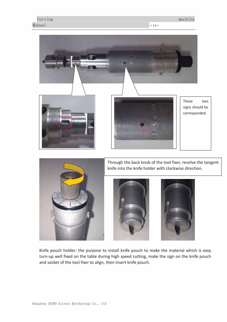
14
Knife pouch holder: the purpose to install knife pouch to make the material which is easy turn-up well fixed on the table during high speed cutting, make the sign on the knife pouch and socket of the tool fixer to align, then insert knife pouch.
These two signs should be corresponded.
Through the back knob of the tool fixer, revolve the tangent knife into the knife holder with clockwise direction.

15
Change oscillating knife: oscillating knife is used most among cutting tools, the
whole oscillating tolls including: oscillating knife, oscillating holder, knife pouch.
Oscillating knife installation: screw off the inside hex screw in the direction of oscillating knife head, insert the oscillating knife into the bottom of the holder and then screw the hex screw.
While installation, these two signs should be corresponded.
Exploded view

16
Oscillating knife holder installation: make the sign on the knife pouch corresponds to the socket of the knife holder, then insert the knife pouch.
Insert the oscillating knife
S
Screw off the screw in anti-clock.
After inserting the oscillating knife igroove, then revolve the screw clockwise direction.

17
3.3.2 Adjust the height of knife
It's very important to adjust the height of knife before cutting, the height of rolling is adjusted rightly or not will have influence on the cutting effect, knife, life of felt, there are 3 ways to adjust the height of rolling: 1.automatic knife matching, 2.minute adjustment manually 3.adjust the height of rolling through setting on the cutter parameter.
1. Automatic knife setting
Automatic knife matching through cutter's knife match tool, firstly insert the knife matching tool in the position hole of knife matching.
While installation, these two signs should be corresponded.
Knife setting device
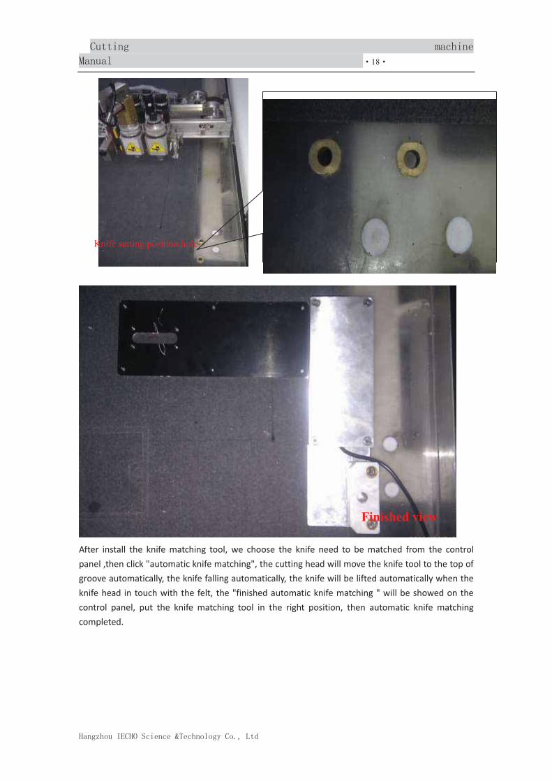
18
After install the knife matching tool, we choose the knife need to be matched from the control panel ,then click "automatic knife matching", the cutting head will move the knife tool to the top of groove automatically, the knife falling automatically, the knife will be lifted automatically when the knife head in touch with the felt, the "finished automatic knife matching " will be showed on the control panel, put the knife matching tool in the right position, then automatic knife matching completed.
Knife setting position hole
Finished view

19
1. Manual micro adjustment
Choose the holder you will do the minute adjustment manually from the control
panel, by click make the knife tool in the cutting height, then click to enter into minute adjustment manually, then control the height of rolling through the direction button through control panel, click one time the direction button "up" which means the knife tool lifted one time, or fell one time, you can set the height of rolling by clicking the direction button every time. Set the height by
holding .
2. Adjust the height of rolling through setting on the cutter parameter. Enter the SK output center, open the cutter parameter, firstly choose the knife tool you need to revise, then revise "the height of material bottom" to control the height of knife falling, the larger the number, the far the knife away from the table, or closer to the table.

20
Item setting value scope unit Machine length machine width speed grade Acceleration value cutting mode common mode Material thickness Machine origin point step factor Verticality knife matching point speed lower edge Repeat times height of material knife tool parameter Pen holder
3.3.3 Maintenance of machine
Vacuum pump will absorb the air continuously when working, the cutting mat hole and
mesh will be jammed by mote, should always clean up these places.
Please keep X, Y rail clean, fill it with lubricating oil regularly
Should change and fill lubricating oil for Air compressor, and drain the pipe regularly.
Should fill lubricating oil for vacuum pump, clean the muffler or change filter. Please
refer to vacuum pump manual.

21
3.4 Machine parameters setting
Open the output center, select parameter
in control center menu, the dialog
opened as below. It is necessary to set
the parameter in the following cases:
1.new installed machine; 2.after
change spare parts; 3.it is necessary to
adjust precision deviation by adjust
software; 4.after change the machine
properties.
In the parameter setting sheet, you can change most of option value, some option is
the drop-down list box, please click the right arrow, then select option as below:

22
After changing the parameter, please click “OK” to save, a dialog box will pop up, input
“1”to finish. And also can save a file for current parameter in your computer, it is done
open the file if the machine parameters need to return to the current data.
3.4.1 Basic parameters of the machine
Set the machine length, width, speed class, acceleration and so on parameter. The test file is: mach_long_ width.plt.

23
3.4.2 Step factor adjustment
Set the test file length, input the actual length. Test file: factor_10_10.plt.
3.4.3 Knife holder shift adjustment
Knife holder 1 install NO.1 Knife, Knife holder 2 install NO.2 Knife, to use offset of knife
holder 1 as references(X_offset Y_offset is Zero),test X direction offset, test file is:
offset_X.plt, test Y direction offset, test file is: offset_y.plt, offset value means the
distance value from knife holder 1, adjust offset of knife holder 1 according offset
value.
Adjust knife holder2,3,…n and pen ,red origin offset as above described.
3.4.4 Other parameters setting
Knife falling time adjustment, shorter time, and faster speed of knife lifting and falling;
Lifting knife value set by click end, smaller of the value, less overcut.
Falling knife value set by click start, smaller of the value, less overcut.
Lifting knife angle Up_angle;
For punch, you can set number of rotations and falling knife.
3. Machine software
4.1 Open pattern file
SK default file format is “cut”. Except to open the “cut” file, it can also open the IECHO
marker pattern. SK support .dxf and .plt file data conversion, and can save these file as
“cut” file.

24
4.1.1 Create new marker
Before importing outer data, please create new marker file, select new in File
menu, or click the create new icon in tool bar, then “marker file info set” dialog box
pop up. You can set the marker width, length, and gap.
4.1.2 Open CUT file
Select open in File menu as below:
Import ECHO online marker (mkm file)

25
4.1.3 Import ECHO online marker (mkm file)
Select import internet marker file in File menu, dialog box shown as below.
Tick “preview marker “at the bottom, then select one file, related information will be
shown for this marker file.
4.1.4 Import external data (dxf and plt file)
Select Import in File menu as below:

26
Click browse, select .PLT file in popped up “import file” dialog box. Choose the unit in
“style unit”. Click “OK”, then come to Data Exchange editing interface.
If need to adjust the pattern, please double click the pattern or select the pattern and
right click mouse, choose “pattern editing ”function to edit the data.
If no need adjust the pattern, please click in tool bar, move the patterns to
unmark area as below:

27
If need import other files, please do above step again, please click .
4.2 Save file
In marker interface, select Save in File menu or click save icon to “save as” dialog.
You can save the marker file as CUT file.
In Data Exchange data editing interface, select export DXF file in File menu, can
save the data in editing interface as DXF file.

28
4.3Marking
4.3.1Set marking attribute
Select setup marker in Marker setting menu.

29
4.3.2 Marking function
Auto marking function—Auto making for patterns in unmark area and marked area.
Click “Auto marking” in tool bar, set the marking parameter in popped up “Auto
marking” dialog box, then click OK to marking.
Parameter specification: Marking manner include: length priority, area priority, position (compress), output priority. Operation object: have four choices, 1. to all pattern (marked area and unmarked area
patterns); 2. To unmarked; 3. To selected; 4. To marked Location manner: undermost and left most. Additional: if select limited area, the system will move these patterns to unmarked area if the patterns exceed the marked area. If select auto pagination, will create new page to marking if the patterns exceed the marked area. Back to unmark area function—sent back the marked patterns to unmark area. Holding “CTRL” in marked area, right click mouse, select “back to unmark area”. Recover unmark—to recover the marked patterns in current marker file and page. Please click “unmark” button. Function declaration: the function of “Back to unmark area” and “Recover unmark” is

30
different, “Back to unmark” cannot change the pattern, for example: if the pattern had rotated or overturned, even Back to unmark area, still keep the status.
4.3.3 Tool menu
Sorting tool
Sorting tools include 4 tools: common way, size (ascending order), size (descending order), and
specification sort
Common way: Sort according to internal order of the unmarked pattern in the unmarked area
Size (ascending order): order sorting according to unmarked pattern area from small to
large
Size (descending order): order sorting according to unmarked pattern area from small to
large
Specification sort: sort through according to the pattern order where in the style of
specification, the result will be for groups to color
Cutting tool-- cutting the pattern in marked area or joining together with patterns that
had cut

31
Cutting patterns dialog box: set how to cut the pattern.
Cutting position: Unit (mm), The cutting position shows that cutting point deviate from
the original place of the pattern, input the number by manual, accurately adjust cutting
position with button “Apply”
Cutting way: There are two ways to cut at present, level cutting and vertical cutting, if select “half and half cut", no matter where is the cutting position, it will be half-and -half setting according to outside rectangle of the pattern Seam: there are two ways of seam, common way is that seam from vertical cutting line in the cutting position ,tangent way is that going down the primary outline from cutting position to seam

32
Sew width: the sew width will appear when indicate seam Pattern tool
Pattern tool include: forced beyond width line forced overlap, overturn, rotation, pattern attribute, etc.
Forced beyond up/down width line tool
Firstly use right button to select the pattern, then click menu “tool" for "cloth pattern tool" for submenu "force beyond down width line" and "forced beyond up width line" , dialog box for forced beyond width line popup
Input the demand number in the dialog box Check the beyond sheet tool Check the pattern groups in the marking area of all beyond setting in the present page of present marking list, and the exceeding quantity information

33
X/Y axis forced overlap tool Forced overlap can force one pattern to overlap on another pattern; there are two ways to activate the function: 1.Firstly click left mouse button to select the pattern, and then move to another pattern, press enter on the keyboard can achieve the function. 2.When two neighboring patterns need to be overlapped, we can use four direction keys to do it. Click each time to move 1mm. Check overlap list tool Check all overlap patterns information in current page of present marking list. Up and down overturn, right and left overturn Control the pattern overturn, click tool, and then click the pattern what you need operate
Contrarotate 45/90 degree tool
Control pattern rotation, click the pattern what you need operate
Congregate tool-- all the patterns in the marked area or selected patterns congregate in one direction. Click menu "tool" for function menu "congregate tool"

34
Image tool
Save the image in the marking area into BMP file
Other tools
Space setting tool: after setting drag the pattern by manual, the distance between
patterns

35
Automatic adjust width function
Adjust the width for Marked marking list automatically, which remove the extra width,
one way to activate it: click pull-down menu “tool" for “other tools" for “automatic
adjust width"
Group tool
The function is that many selected patterns group as a whole, whatever move or drag,
they are as a whole, moreover not use the function of separate, it always exist. One
way to activate it:
1. After selecting many patterns, click pull-down menu "tool" for "group tool", then for
"group" to activate the function

36
2. Separate the patterns function is after selecting group patterns, click pull-down menu "tool" for "gang up" under "gang up tool”, then activate the function Notice: shortcut key for these two functions is F7 for group, F8 for separate
4.3.4 Function setting of marking system
System tool setting dialog box

37
Parameter setting description: Movement length:(unit)mm, the parameter will work when press direction key on the keyboard ,press for one time, the distance for moving up, down, left and right, the minimum distance is 0.5mm Knife edge length:(unit)mm, after finish setting the parameter, the knife edge for formed pattern will get length according to the parameter, but this parameter has no effect in generated pattern, no effect also for saved marking list. Rotation angle amplitude: unit)degree, the parameter is used for pressing the rotation button each time, the range for pattern rotation. The angle for rotation is at least 0.1 degree. Find bound limit: When the pattern impact on detection, to search for the accuracy of position, 1-100,1for accuracy finding, but the speed will be slow, default precision is 5 Limit overturn: select the parameter, system will stop overturn request for all the

38
patterns Limit rotation: select the parameter, system will stop rotation request for all the patterns Limit overlap: select the parameter, in common way, pattern can't be overlapped, if put the pattern position overlapped with other pattern, the pattern will be bound automatically, find no position of overlap
Open back function: select the parameter, the operation for marking list, such as move, copy, delete, mirror will be recorded, so that allow back operations Notes: use this function will cause empty processing of all the record of current marking list Adjustment priority: select the parameter; it will adjust the function of right button for dragging the pattern in order to only drag the pattern character. Show overlap number anytime: select the parameter, in the process of moving pattern, if overlap happens, the overlap station for present pattern group will reflect in the overlap dialog box Notes: little move for direction key cause pattern overlap that will not bring overlap dialog box popup at any time, even if selected the parameter. Data-base lookup priority: the parameter will cause the function of exchange model such as open and from the open function, save and save as. Selected the parameter, increase marked list, lookup marked list will take the way of open data-base, otherwise adopt any way to open Overturn linkage: when chose style, if pattern appear pairs is that chose both positive and negative side, selected the parameter, if one of the pattern cause overturn, well then another pattern will be also overturn, otherwise only overturn present selected pattern. Fill in color display: indicate all the patterns in marked area and unmarked area, whether display the pattern of fill in color. Display net panel: whether all the patterns display net panel Display internal line: whether all the patterns display their own internal line Display knife edge: whether all the patterns display their own knife edge for gross and net panel Display gridding: whether all the patterns show their gridding Display Matching plaid: whether all the patterns show their own Matching pattern and plaid. Display grain: whether all the patterns display grain line Display stitches: whether all the patterns display stitches for putting seam after cutting
Display sepal line: whether all the patterns display virtual sepal line between patterns after setting marking gap Display matching plaid line: whether matching plaid line display in marking list area

39
Open anti-aliasing: when marking list shows, whether open anti-aliasing, anti-aliasing will improved in softness of curves, but there will be some effect in refresh speed of system.
4.4 Data edit
4.4.1Simple editing of patterns
Use left key to double click single pattern in SmartCut AutoPlan marking list that need
to edit, enter into interface of smartcut data edit. As followed picture:
Click tool menu bar, point to submenus (parameter setting), appears knife and pen
setting interface as below

40
(1)There are knife position, show text, and knife move direction in the display setting,
select the three options will display corresponding character in the patterns, as below
picture:
2 Selected color refers to the selected samples of the line color, background color
refers to the color at the blank screen. They can be set according to their preferences.
To prevent color conflict, leading to sample can not be displayed.

41
Tool shows the color is referring to the color of the sample line. Each color and SP value,
cutting tool type is the one-to-one. Change line color to ensure its uniqueness, and can
not with the selected color, background color conflict.
Here in the revision and marking interface from Control Center under the menu Pen
Color Settings submenu open “Knife & Pen Settings” dialog box is the same.
Tool type and SP value of the corresponding relationship is formed by cutting
equipment attribute decision, every amendment cutting tool attributes, they can
automatically link, here can not be changed.
(3)Optional parameters: have the border, amplification proportion, and merger end connection and rotation angle.
4.4.2Modification of imported external data
When import DXF or PLT file, in Data Exchange interface can be modified to sample. As the chart:
Here, in addition to can modify the sample line cutting drawing properties, and also
can delete, move, copy, rotating, mirroring, scaling and other operations.
Special editing: Automatic recognition of punching pieces-modification of round hole
sample cutting draw for punching attribute types.

42
Right-click the space below, on the shortcut menu, select [Automatic Identification
Punching]-[Punching 1], the associated hole is changed to punching data, and the color
is also changed accordingly. (Note: The automatic of the menu item is relevant with
punching cutting tool configuration. Cutting punch hole configuration and sample size
to be consistent, otherwise the sample can not be identified successfully.)
The editor of a single sample:
In the Data Exchange interface, double-click a sample, open SmartCut-data editing
interface. Here, the interface is similar to the data editing interface from the opening
SmartCut. But here you can delete, copy, move, rotate, mirror, scaling and other
operations, also have the special function.
Select the appropriate line or point, click right key to operate of need. As the chart:
Setting up the knife point can be changed from a knife position; delete point can delete
the selected point, optimizing the cutting path.
Using the left side of the toolbar can also add in the sample of simple graphics and text.
4.5 Machine output setting
4.5.1 Configure software relative parameters according to machine
Choose Control Center menu of Cutting Parameters submenu or click on the
toolbar to enter in the machine “Parameters Settings” interface.

43
Input the correct IP address; click OK to enter the machine “Parameter Setting” interface.
Check the knife holder whether it is configured properly or not, then click OK, in the
pop-up password dialog box, enter password and click OK. Thus complete the cutting
software whose parameters match automatically. Choose Control Center menu of
Pen Color Settings submenu, in the pop-up “Knife & Pen Settings” dialog box can

44
see tool type, SP value, equipment cutter and cutting parameters of the configuration
is one-to-one. When the computer use cutting equipment before or replace cutting
tool (cutting tool head configuration parameter modification) should be read once
cutting parameters.
4.5.2 Appoint cutting and plotting attribute of knife and pen
In addition to the data editing in the module of knife & pen attribute sample set lines
outside, there is also a simple method that can achieve the same function. Choose
Control Center menu of All the samples of Knife & Pen Settings submenu, open
the “ Designated all the samples of knife & pen” dialog box, here can complete the
outline, inside, the sword of the attributes of the fast cutting tools designated.
4.5.3Appoint the cutting sequence
Through Tools menu- Cutting Order ,under the submenu of Automatic Cutting
Ordering and Manual Cutting Sequence Adjustment ,can change the discharging
single in the sample has an output order.

45
4.5.4Appoint the output line and sequence
When send the discharge diagram to cutting equipment, you can select the output line
according to the knife & pen attribution of samples. Choose Control Center menu
of Output Settings ,open the “ Output Settings” dialog box.
Selection of sample output: Only output the selected samples.
In the “Select Output Line and the Output Order” options selected for output tool line,
the order of choice will determine the order of the output, if you want to sort, click on
the lower right corner of the “Empty”.
Smooth output: when the smooth rate of sample by cutting can not meet the needs of
cutting degree, you can choose the option of smooth output, then sample to optimize
the output, at the same time, set the sample density set to 5mm generally.

46
4.5.5Send the parameters debug file
Cutting precision, knife base and accuracy of cutting tools can be used to set the special
file, special file is sent in the “Parameter Debugging” interface completed.
Choose Control Center menu of Parameter Debugging submenu, in debugging
parameters dialog box click the test file, select the test object corresponding to the file,
then click the test object button, documents will be sent to cutting machine. Then cut
on the cardboard according to the normal cutting method, according to the cutting
effect on tool to adjust or modify parameters.
5. Common trouble removal of machine
1. Cutting machine can not start
� Check the cutting power plug whether it is inserted or not.
2. Cutting material absorb is not tight.
� Cutting material whether needs to be covered with plastic film or not.
� Check the cutting vacuum chamber whether leaks, pump suction pipe
whether leaks.
3. Cutting pattern file can not be transferred
� Check the equipment and use computer IP address is set correctly. IP address
settings of SK software are correct.
� Check the cable is properly connected, dual Internet use cross line, please use
the direct line access network.
4. Can not cut through
� Cutter depth is not enough; increase the depth of cutting tool appropriately.
� Replace new blade
� Part of the cutting material has “not cut off completely” phenomenon, please
put a layer of punched paper on table-board before accessories.

47
5. Samples of turning or vertex cutting dose not reach the designated position, not
cutting
� Enter “ Machine Parameters Settings” dialog box, reset the over cutting
software shortcut key explanation
Function keys: F1: Select a single sample press F1 into data editing window
F3: Samples of discharge area to arrange automatically
F4: Open the patterns of unmarked area for automatic window
F5: Select a single sample press F5 into sample attribute settings dialog window
F7: Sample group: Select multiple samples press F7 to get a group
F8 Separate group: Select the group which sets up, press F8, and then separates it.
F9: Select a single sample press F9 into the display window of adjust sample.
Number keys: Numpad 1: Sample is rotated 45 degrees counter-clockwise
Numpad 2: Sample is rotated 90 degrees counter-clockwise
Numpad 3: Sample is rotated 1 degree counter-clockwise
Numpad 4: Sample is rotated 1 degree clockwise
Numpad 5: Sample is rotated 180 degrees counter-clockwise
Direction keys: ↑ Sample move up
↓ Sample move down
→ Sample move right
← Sample move left
Other shortcuts: W Sample by up
D: Sample by right
S Sample by left
A: Sample by down

48
Q: Sample by upper left
E: Sample by upper right
Z: Sample by lower left
C: Sample by lower right