technical data ratosplus 10/2014
DESCRIPTION
ÂTRANSCRIPT

RATO S+TECHNISCHE DATEN TECHNICAL DATA

Das Handsymbol kennzeichnet Seiten, auf denen es eine Veränderung zur Vorgängerversion gibt.The hand symbol appears on pages which differ from the previous catalogue version.08/2016
Bitte benutzen Sie Ihr Smartphone mit der entsprechenden Software, scannen Sie den QR-Code ein.
Please use your smartphone with the relevant software, scan the QR-Code.
Sie erhalten die Information, ob dies die aktuellste Version ist.
You will get the information whether you have got the latest version.
SCAN GET INFO INFO

03RATO S+ VULKAN COUPLINGS
INHALT CONTENTS
04 EIGENSCHAFTEN RATO S+
CHARACTERISTICS RATO S+
06 BAUREIHENÜBERSICHT RATO S+
SUMMARY OF SERIESRATO S+
08 TECHNISCHE DATEN RATO S+
TECHNICAL DATARATO S+
LEISTUNGSDATEN PERFORMANCE DATA
08 RATO S+ 08 RATO S+
GEOMETRISCHE DATEN GEOMETRIC DATA
10 Baureihe 2100 10 Series 2100
12 Baureihe 2101 12 Series 2101
14 Baureihe 2200 14 Series 2200
16 Baureihe 2201 16 Series 2201
18 ERLÄUTERUNGEN DES PRODUKTCODESRATO S+
EXPLANATIONS OF THE PRODUCT CODERATO S+
22 ONLINE-SERVICE ONLINE-SERVICE
23 GÜLTIGKEITSKLAUSEL VALIDITY CLAUSE

05VULKAN COUPLINGSRATO S+
DREHMOMENT TORQUE RANGE180.0 kNm – 360.0 kNm
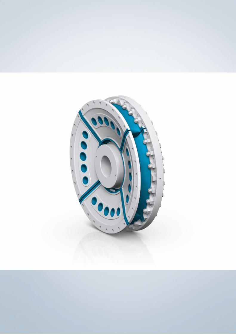
RATO S+EIGENSCHAFTEN CHARACTERISTICS
08/2016
EINSATZGEBIETE
Elastisch aufgestellte Anlagen, starr aufgestellte Anlagen.
Die hochelastische RATO S+ Kupplung ist eine drehelastische Elastomerkupplung,
die radiale, axiale und winklige Verlagerungen der angeschlossenen Maschinen
ausgleicht. Die Drehmomentübertragung der Kupplung wird durch die auf Schub
beanspruchten Elemente gewährleistet. Durch die verschiedenen zur Verfügung
stehenden Drehsteifigkeiten und Dämpfungen ist eine gute Abstimmung des
Drehschwingungsverhaltens der Antriebsanlage zu erreichen. Die neuentwickelten
Produkte der ACOTEC Serie zeichnen sich durch eine gesteigerte Leistungsfähigkeit
in den wesentlichen technischen Daten aus.
PRODUKTVORTEILE
Kleinere Kupplung mit höherer Leistungsdichte
sorgt für ein gutes Preis-Leistungsverhältnis
Innovatives Design nimmt zukünftige Leistungs- bzw.
Drehzahlerhöhungen der Motoren vorweg
Reduzierte Mittelmasse bringt signifikanten Gewichtsvorteil
für geforderte Leichtbauweise
AREAS OF APPLICATION
Flexibly mounted engines, rigidly mounted engines.
The highly-flexible RATO S+ coupling is a torsionally flexible rubber coupling that
compensates radial, axial and angular shaft displacements of the connected
machinery. The torque is transmitted by elements loaded in shear. The different
torsional stiffnesses and damping factors available provide the possibility to satis-
factorily tune the torsional vibration behaviour of the drive system. The newly
developed ACOTEC series products are characterized by improved performance
in the essential technical data.
BENEFITS
Smaller coupling with higher power density ensures lower project costs
thanks to a more favourable price-performance ratio
Innovative design anticipates enhancements in the
power and speed of the engines
Reduced mean mass provides significant advantages for the weight
of the lightweight construction required

06 VULKAN COUPLINGS RATO S+
RATO S+BAUREIHENÜBERSICHT SUMMARY OF SERIES
08/2016
2100BAUREIHE SERIES
Seite 12 Page 12
Zur Verbindung eines Schwungrades mit einer Welle.Mit innen liegender Nabe. Hierdurch wird eine deutlich reduzierte Baulänge ermöglicht.
For connecting a flywheel with a shaft.With internal hub arrangement, that ensures a compact coupling design.
Baugruppe Dimension Group G 4J10 – G 5G20
Nenndrehmoment Nominal Torque 180.00 kNm – 360.00 kNm
2101BAUREIHE SERIES
Seite 16 Page 16
Zur Verbindung eines Schwungrades mit einer Welle.Mit innen liegender Nabe. Hierdurch wird eine deutlich reduzierte Baulänge ermöglicht. Mit Durchdrehsicherung.
For connecting a flywheel with a shaft.With internal hub arrangement, that ensures a compact coupling design. With torsional limit device.
Baugruppe Dimension Group G 4J10 – G 5G20
Nenndrehmoment Nominal Torque 180.00 kNm – 360.00 kNm

07VULKAN COUPLINGSRATO S+08/2016
2200BAUREIHE SERIES
Seite 20 Page 20
Zur Verbindung eines Schwungrades mit einer Welle.
For connecting a flywheel with a shaft.
Baugruppe Dimension Group G 4J10 – G 5G20
Nenndrehmoment Nominal Torque 180.00 kNm – 360.00 kNm
2201BAUREIHE SERIES
Seite 24 Page 24
Zur Verbindung eines Schwungrades mit einer Welle.Mit Durchdrehsicherung.
For connecting a flywheel with a shaft. With torsional limit device.
Baugruppe Dimension Group G 4J10 – G 5G20
Nenndrehmoment Nominal Torque 180.00 kNm – 360.00 kNm

08 VULKAN COUPLINGS RATO S+
RATO S+
LEISTUNGSDATEN PERFORMANCE DATA
Kupplungstyp Type of Coupling TKN TKmax1 TKmax2 ΔTKmax TKW PKV50 nKmax
2) ΔKa ΔKr‘2) Crdyn CTdyn1) 2) ψ1) 2)
[kNm] [kNm] [kNm] [kNm] [kNm] [kW] [1/min] [mm] [mm] [kN/mm] [kNm/rad]nominal
nominal
Größe Baugruppe Nenndreh-moment
Max. Dreh moment1
Max. Dreh moment2
Drehmoment Bereich
Wechsel-drehmoment
Verlust leistung Drehzahl AxialerKupplungsversatz
Radialer Kupplungsversatz
Radiale Federsteife
DynamischeDrehfedersteife
Verhältnismäßige Dämpfung
Size Dimension Group
Nominal Torque Max. Torque1 Max. Torque2 Torque Range
Vibratory Torque
Power Loss
Rotational Speed
Axial Coupling Displacement
Radial Coupling Displacement
Radial Stiffness
Dynamic Tor sional Stiffness
Relative Damping
G 4J1S G 4J10 180,0 220,0 810,0 275,0 53,0 1,48 800 12,0 13,0 6,8 1300 0,75G 4J1M G 4J10 210,0 265,0 945,0 320,0 55,0 1,48 800 12,0 11,0 9,4 1800 0,90G 4J1H G 4J10 225,0 295,0 1012,5 355,0 55,0 1,48 800 12,0 9,0 11,5 2200 0,90G 4J1X G 4J10 225,0 325,0 1012,5 390,0 55,0 1,48 800 12,0 6,0 14,4 2750 1,13G 4J2S G 4J20 180,0 220,0 810,0 275,0 53,0 2,96 690 12,0 26,0 3,4 650 0,75G 4J2M G 4J20 210,0 265,0 945,0 320,0 55,0 2,96 690 12,0 22,0 4,7 900 0,90G 4J2H G 4J20 225,0 295,0 1012,5 355,0 55,0 2,96 690 12,0 18,0 5,7 1100 0,90G 4J2X G 4J20 225,0 325,0 1012,5 390,0 55,0 2,96 690 12,0 12,0 7,2 1375 1,13
G 5B1S G 5B10 230,0 285,0 1035,0 345,0 65,0 1,53 750 13,0 14,0 8,1 1800 0,75G 5B1M G 5B10 250,0 330,0 1125,0 400,0 70,0 1,53 750 13,0 12,0 10,1 2250 0,90G 5B1H G 5B10 280,0 370,0 1260,0 440,0 70,0 1,53 750 13,0 10,0 12,4 2750 0,90G 5B1X G 5B10 290,0 410,0 1305,0 485,0 70,0 1,53 750 13,0 6,0 15,3 3400 1,13G 5B2S G 5B20 230,0 285,0 1035,0 345,0 65,0 3,06 690 13,0 28,0 4,0 900 0,75G 5B2M G 5B20 250,0 330,0 1125,0 400,0 70,0 3,06 690 13,0 24,0 5,0 1125 0,90G 5B2H G 5B20 280,0 370,0 1260,0 440,0 70,0 3,06 690 13,0 20,0 6,2 1375 0,90G 5B2X G 5B20 290,0 410,0 1305,0 485,0 70,0 3,06 690 13,0 12,0 7,6 1700 1,13G 5G1S G 5G10 290,0 360,0 1305,0 435,0 80,0 1,72 700 14,0 15,0 8,9 2300 0,75G 5G1M G 5G10 310,0 415,0 1395,0 500,0 85,0 1,72 700 14,0 13,0 10,8 2800 0,90G 5G1H G 5G10 345,0 465,0 1552,5 555,0 85,0 1,72 700 14,0 11,0 13,4 3465 0,90G 5G1X G 5G10 360,0 510,0 1620,0 615,0 85,0 1,72 700 14,0 7,0 16,6 4300 1,13G 5G2S G 5G20 290,0 360,0 1305,0 435,0 80,0 3,44 690 14,0 30,0 4,4 1150 0,75G 5G2M G 5G20 310,0 415,0 1395,0 500,0 85,0 3,44 690 14,0 26,0 5,4 1400 0,90G 5G2H G 5G20 345,0 465,0 1552,5 555,0 85,0 3,44 690 14,0 22,0 6,7 1732 0,90G 5G2X G 5G20 360,0 510,0 1620,0 615,0 85,0 3,44 690 14,0 14,0 8,3 2150 1,13
Siehe Erläuterung der Technischen Daten.Andere Steifigkeiten auf Anfrage.1) VULKAN empfiehlt die zusätzliche Berücksichtigung von CTdyn warm (0,7), CTdyn la (1,35)
und ψ warm (0,7) für die Berechnung der Drehschwingungen in der Anlage.2) Der Betriebszustand der Anlage kann eine Korrektur der gegebenen Werte notwendig machen.
Durch die Eigenschaften des Werkstoffs Gummi sind Toleranzen der angeführten Daten für CTdyn von ±15 % und für ψ von +10 %/-20 % möglich.
See Explanation of the Technical Data. Different stiffnesses on request.1) VULKAN recommends additionally taking into account CTdyn warm (0,7), CTdyn la (1,35) and
ψ warm (0,7) for calculating the torsional vibration in the system.2) The actual operating condition could require the correction of the given values.
Due to the properties of elastic elements, tolerances in the technical data of ± 15% for CTdyn and +10 %/-20 % for ψ are possible.
08/2016

09VULKAN COUPLINGSRATO S+

10 VULKAN COUPLINGS RATO S+
GEOMETRISCHE DATEN GEOMETRIC DATA
Baugruppe Abbildung Abmessungen Massenträgheitsmomente Masse Schwerpunktsabstand AnmerkungenDimension Group Figure Dimension Mass moments of inertia Mass Distance to center of gravity Notes
D1 D3 D14 D15 T1 D16 L1 L2 L7 J1 J2 J3 m1 m2 m3 S1 S2 S3 Alle Massen, Schwerpunkte und Massen-trägheitsmomente beziehen sich auf min. Nabendurchmesser.
All masses, focal points and mass moments of inertia refer to min. hub diameter.
[mm] [mm] [mm] [mm] [mm] [-] [mm] [mm] [mm] [mm] [kgm²] [kgm²] [kgm²] [kg] [kg] [kg] [mm] [mm] [mm]Min. Max. Teilung / holes
G 4J10 A 1480,0 230,0 370,0 1460,0 1395,0 32 33,0 441,7 410,0 33,0 97,8 279,1 – 311,0 1403,0 – 57,0 174,0 –G 4J20 B 1480,0 230,0 370,0 1460,0 1395,0 32 33,0 621,9 480,0 33,0 97,8 166,6 296,7 311,0 543,0 1565,0 57,0 392,0 182,0
G 5B10 A 1585,0 250,0 400,0 1565,0 1500,0 32 33,0 439,6 400,0 32,0 132,8 330,3 – 371,0 1463,0 – 61,0 175,0 –G 5B20 B 1585,0 250,0 400,0 1565,0 1500,0 32 33,0 655,0 500,0 32,0 132,8 226,5 387,0 371,0 641,0 1776,0 61,0 411,0 198,0G 5G10 A 1710,0 280,0 430,0 1685,0 1615,0 32 36,0 472,9 425,0 35,0 190,4 484,0 – 457,0 1836,0 – 65,0 189,0 –G 5G20 B 1710,0 280,0 430,0 1685,0 1615,0 32 36,0 688,6 520,0 35,0 190,4 332,8 540,4 457,0 810,0 2133,0 65,0 429,0 202,0
RATO S+ 2100
A B
Ø D
16
Ø D
14 h
6
Ø D
15 T
1
Ø D
1
Ø D
3 M
in.
Ø D
3 M
ax.
L2
L1
L7
S1
M1
S2
M2
L7
L1
Ø D
3 M
in.
Ø D
3 M
ax.
S1
M1
Ø D
16
Ø D
15 T
1
ØD
14 h
6
L2
S3
M3
S2
M2
Ø D
1
BAUREIHE SERIES
08/2016

11VULKAN COUPLINGSRATO S+
GEOMETRISCHE DATEN GEOMETRIC DATA
Baugruppe Abbildung Abmessungen Massenträgheitsmomente Masse Schwerpunktsabstand AnmerkungenDimension Group Figure Dimension Mass moments of inertia Mass Distance to center of gravity Notes
D1 D3 D14 D15 T1 D16 L1 L2 L7 J1 J2 J3 m1 m2 m3 S1 S2 S3 Alle Massen, Schwerpunkte und Massen-trägheitsmomente beziehen sich auf min. Nabendurchmesser.
All masses, focal points and mass moments of inertia refer to min. hub diameter.
[mm] [mm] [mm] [mm] [mm] [-] [mm] [mm] [mm] [mm] [kgm²] [kgm²] [kgm²] [kg] [kg] [kg] [mm] [mm] [mm]Min. Max. Teilung / holes
G 4J10 A 1480,0 230,0 370,0 1460,0 1395,0 32 33,0 441,7 410,0 33,0 97,8 279,1 – 311,0 1403,0 – 57,0 174,0 –G 4J20 B 1480,0 230,0 370,0 1460,0 1395,0 32 33,0 621,9 480,0 33,0 97,8 166,6 296,7 311,0 543,0 1565,0 57,0 392,0 182,0
G 5B10 A 1585,0 250,0 400,0 1565,0 1500,0 32 33,0 439,6 400,0 32,0 132,8 330,3 – 371,0 1463,0 – 61,0 175,0 –G 5B20 B 1585,0 250,0 400,0 1565,0 1500,0 32 33,0 655,0 500,0 32,0 132,8 226,5 387,0 371,0 641,0 1776,0 61,0 411,0 198,0G 5G10 A 1710,0 280,0 430,0 1685,0 1615,0 32 36,0 472,9 425,0 35,0 190,4 484,0 – 457,0 1836,0 – 65,0 189,0 –G 5G20 B 1710,0 280,0 430,0 1685,0 1615,0 32 36,0 688,6 520,0 35,0 190,4 332,8 540,4 457,0 810,0 2133,0 65,0 429,0 202,0
08/2016

12 VULKAN COUPLINGS RATO S+
GEOMETRISCHE DATEN GEOMETRIC DATA
Baugruppe Abbildung Abmessungen Massenträgheitsmomente Masse Schwerpunktsabstand AnmerkungenDimension Group Figure Dimension Mass moments of inertia Mass Distance to center of gravity Notes
D1 D3 D10 D14 D15 T1 D16 L1 L2 L4 L7 J1 J2 J3 m1 m2 m3 S1 S2 S3 Alle Massen, Schwerpunkte und Massen-trägheitsmomente beziehen sich auf min. Nabendurchmesser.
All masses, focal points and mass moments of inertia refer to min. hub diameter.
[mm] [mm] [mm] [mm] [mm] [mm] [-] [mm] [mm] [mm] [mm] [mm] [kgm²] [kgm²] [kgm²] [kg] [kg] [kg] [mm] [mm] [mm]Min. Max. Teilung / holes
G 4J10 A 1480,0 230,0 370,0 1480,0 1460,0 1395,0 32 33,0 469,7 410,0 12,0 61,0 183,6 285,6 – 546,0 1488,0 – 59,0 189,0 –G 4J20 B 1480,0 230,0 370,0 1480,0 1460,0 1395,0 32 33,0 649,7 480,0 12,0 61,0 183,8 166,6 267,9 547,0 543,0 1578,0 59,0 391,0 217,0
G 5B10 A 1585,0 250,0 400,0 1585,0 1565,0 1500,0 32 33,0 470,0 400,0 12,0 62,0 262,0 316,0 – 658,0 1508,0 – 61,0 171,0 –G 5B20 B 1585,0 250,0 400,0 1585,0 1565,0 1500,0 32 33,0 685,2 500,0 12,0 62,0 262,0 226,5 339,0 658,0 641,0 1921,0 61,0 411,0 235,0G 5G10 A 1710,0 280,0 430,0 1710,0 1685,0 1615,0 32 36,0 505,0 435,0 12,0 67,0 365,3 506,0 – 807,0 1998,0 – 64,0 209,0 –G 5G20 B 1710,0 280,0 430,0 1710,0 1685,0 1615,0 32 36,0 720,6 520,0 12,0 67,0 374,0 332,8 491,0 829,0 810,0 2384,0 64,0 429,0 241,0
RATO S+ 2101BAUREIHE SERIES
A B
L4
L7
L1
L2
Ø D
3 M
in.
Ø D
3 M
ax.
Ø D
1
Ø D
16
Ø D
15 T
1
Ø D
14 h
6
Ø D
10
S2
M2
S1
M1
Ø D
1
Ø D
3 M
in.
Ø D
3 M
ax.
L1
L7
Ø D
10
Ø D
14 h
6
Ø D
15 T
1
Ø D
16
L2
S3
M3
S2
M2
S1
M1
L4
08/2016

13VULKAN COUPLINGSRATO S+
GEOMETRISCHE DATEN GEOMETRIC DATA
Baugruppe Abbildung Abmessungen Massenträgheitsmomente Masse Schwerpunktsabstand AnmerkungenDimension Group Figure Dimension Mass moments of inertia Mass Distance to center of gravity Notes
D1 D3 D10 D14 D15 T1 D16 L1 L2 L4 L7 J1 J2 J3 m1 m2 m3 S1 S2 S3 Alle Massen, Schwerpunkte und Massen-trägheitsmomente beziehen sich auf min. Nabendurchmesser.
All masses, focal points and mass moments of inertia refer to min. hub diameter.
[mm] [mm] [mm] [mm] [mm] [mm] [-] [mm] [mm] [mm] [mm] [mm] [kgm²] [kgm²] [kgm²] [kg] [kg] [kg] [mm] [mm] [mm]Min. Max. Teilung / holes
G 4J10 A 1480,0 230,0 370,0 1480,0 1460,0 1395,0 32 33,0 469,7 410,0 12,0 61,0 183,6 285,6 – 546,0 1488,0 – 59,0 189,0 –G 4J20 B 1480,0 230,0 370,0 1480,0 1460,0 1395,0 32 33,0 649,7 480,0 12,0 61,0 183,8 166,6 267,9 547,0 543,0 1578,0 59,0 391,0 217,0
G 5B10 A 1585,0 250,0 400,0 1585,0 1565,0 1500,0 32 33,0 470,0 400,0 12,0 62,0 262,0 316,0 – 658,0 1508,0 – 61,0 171,0 –G 5B20 B 1585,0 250,0 400,0 1585,0 1565,0 1500,0 32 33,0 685,2 500,0 12,0 62,0 262,0 226,5 339,0 658,0 641,0 1921,0 61,0 411,0 235,0G 5G10 A 1710,0 280,0 430,0 1710,0 1685,0 1615,0 32 36,0 505,0 435,0 12,0 67,0 365,3 506,0 – 807,0 1998,0 – 64,0 209,0 –G 5G20 B 1710,0 280,0 430,0 1710,0 1685,0 1615,0 32 36,0 720,6 520,0 12,0 67,0 374,0 332,8 491,0 829,0 810,0 2384,0 64,0 429,0 241,0
08/2016

14 VULKAN COUPLINGS RATO S+
GEOMETRISCHE DATEN GEOMETRIC DATA
Baugruppe Abbildung Abmessungen Massenträgheitsmomente Masse Schwerpunktsabstand AnmerkungenDimension Group Figure Dimension Mass moments of inertia Mass Distance to center of gravity Notes
D1 D3 D14 D15 T1 D16 L1 L2 L7 J1 J2 J3 m1 m2 m3 S1 S2 S3 Alle Massen, Schwerpunkte und Massen-trägheitsmomente beziehen sich auf min. Nabendurchmesser.
All masses, focal points and mass moments of inertia refer to min. hub diameter.
[mm] [mm] [mm] [mm] [mm] [-] [mm] [mm] [mm] [mm] [kgm²] [kgm²] [kgm²] [kg] [kg] [kg] [mm] [mm] [mm]Min. Max. Teilung / holes
G 4J10 A 1480,0 230,0 370,0 1460,0 1395,0 32 33,0 779,7 480,0 33,0 97,8 283,4 – 311,0 1508,0 – 57,0 391,0 –G 4J20 B 1480,0 230,0 370,0 1460,0 1395,0 32 33,0 958,2 480,0 33,0 97,8 166,6 301,0 311,0 543,0 1670,0 57,0 728,0 400,0
G 5B10 A 1585,0 250,0 400,0 1565,0 1500,0 32 33,0 808,8 500,0 32,0 132,8 343,2 – 371,0 1671,0 – 61,0 402,0 –G 5B20 B 1585,0 250,0 400,0 1565,0 1500,0 32 33,0 1013,0 500,0 32,0 132,8 226,5 395,0 371,0 641,0 1907,0 61,0 769,0 420,0G 5G10 A 1710,0 280,0 430,0 1685,0 1615,0 32 36,0 847,8 520,0 35,0 190,4 504,5 – 457,0 2056,0 – 65,0 422,0 –G 5G20 B 1710,0 280,0 430,0 1685,0 1615,0 32 36,0 1063,4 520,0 35,0 190,4 332,8 551,0 457,0 810,0 2282,0 65,0 804,0 438,0
RATO S+ 2200BAUREIHE SERIES
A B
Ø D
14 h
6
Ø D
15 T
1
Ø D
16
L1
L7
Ø D
3 M
in.
Ø D
3 M
ax.
Ø D
1
S2
M2
S1
M1
L2
L1
L7
Ø D
3 M
in.
Ø D
3 M
ax.
Ø D
1
Ø D
15 T
1
Ø D
14 h
6
Ø D
16
L2
S1
M1
S3
M3
S2
M2
08/2016

15VULKAN COUPLINGSRATO S+
GEOMETRISCHE DATEN GEOMETRIC DATA
Baugruppe Abbildung Abmessungen Massenträgheitsmomente Masse Schwerpunktsabstand AnmerkungenDimension Group Figure Dimension Mass moments of inertia Mass Distance to center of gravity Notes
D1 D3 D14 D15 T1 D16 L1 L2 L7 J1 J2 J3 m1 m2 m3 S1 S2 S3 Alle Massen, Schwerpunkte und Massen-trägheitsmomente beziehen sich auf min. Nabendurchmesser.
All masses, focal points and mass moments of inertia refer to min. hub diameter.
[mm] [mm] [mm] [mm] [mm] [-] [mm] [mm] [mm] [mm] [kgm²] [kgm²] [kgm²] [kg] [kg] [kg] [mm] [mm] [mm]Min. Max. Teilung / holes
G 4J10 A 1480,0 230,0 370,0 1460,0 1395,0 32 33,0 779,7 480,0 33,0 97,8 283,4 – 311,0 1508,0 – 57,0 391,0 –G 4J20 B 1480,0 230,0 370,0 1460,0 1395,0 32 33,0 958,2 480,0 33,0 97,8 166,6 301,0 311,0 543,0 1670,0 57,0 728,0 400,0
G 5B10 A 1585,0 250,0 400,0 1565,0 1500,0 32 33,0 808,8 500,0 32,0 132,8 343,2 – 371,0 1671,0 – 61,0 402,0 –G 5B20 B 1585,0 250,0 400,0 1565,0 1500,0 32 33,0 1013,0 500,0 32,0 132,8 226,5 395,0 371,0 641,0 1907,0 61,0 769,0 420,0G 5G10 A 1710,0 280,0 430,0 1685,0 1615,0 32 36,0 847,8 520,0 35,0 190,4 504,5 – 457,0 2056,0 – 65,0 422,0 –G 5G20 B 1710,0 280,0 430,0 1685,0 1615,0 32 36,0 1063,4 520,0 35,0 190,4 332,8 551,0 457,0 810,0 2282,0 65,0 804,0 438,0
08/2016

16 VULKAN COUPLINGS RATO S+
GEOMETRISCHE DATEN GEOMETRIC DATA
Baugruppe Abbildung Abmessungen Massenträgheitsmomente Masse Schwerpunktsabstand AnmerkungenDimension Group Figure Dimension Mass moments of inertia Mass Distance to center of gravity Notes
D1 D3 D10 D14 D15 T1 D16 L1 L2 L4 L7 J1 J2 J3 m1 m2 m3 S1 S2 S3 Alle Massen, Schwerpunkte und Massen-trägheitsmomente beziehen sich auf min. Nabendurchmesser.
All masses, focal points and mass moments of inertia refer to min. hub diameter.
[mm] [mm] [mm] [mm] [mm] [mm] [-] [mm] [mm] [mm] [mm] [mm] [kgm²] [kgm²] [kgm²] [kg] [kg] [kg] [mm] [mm] [mm]Min. Max. Teilung / holes
G 4J10 A 1480,0 230,0 370,0 1480,0 1460,0 1395,0 32 33,0 808,0 480,0 12,0 61,0 191,0 282,0 – 548,0 1744,0 – 56,0 401,0 –G 4J20 B 1480,0 230,0 370,0 1480,0 1460,0 1395,0 32 33,0 986,0 480,0 12,0 61,0 184,5 166,6 314,6 547,0 543,0 1858,0 57,0 728,0 447,0
G 5B10 A 1585,0 250,0 400,0 1585,0 1565,0 1500,0 32 33,0 839,0 500,0 12,0 62,0 262,0 344,0 – 658,0 1984,0 – 61,0 420,0 –G 5B20 B 1585,0 250,0 400,0 1585,0 1565,0 1500,0 32 33,0 1043,0 500,0 12,0 62,0 256,0 226,5 414,0 663,0 641,0 2146,0 60,0 769,0 474,0G 5G10 A 1710,0 280,0 430,0 1710,0 1685,0 1615,0 32 36,0 880,0 520,0 12,0 67,0 374,0 497,0 – 829,0 2453,0 – 64,0 440,0 –G 5G20 B 1710,0 280,0 430,0 1710,0 1685,0 1615,0 32 36,0 1095,5 520,0 12,0 67,0 374,0 332,8 500,0 829,0 810,0 2547,0 64,0 804,0 474,0
RATO S+ 2201BAUREIHE SERIES
A BL1
L7
L4
Ø D
10
Ø D
15 T
1
Ø D
14 h
6
Ø D
16
Ø D
1
Ø D
3 M
in.
Ø D
3 M
ax.
L2
S2
M2
S1
M1
L2
L1
L4
L7
Ø D
15 T
1
Ø D
14 h
6
Ø D
16
Ø D
10
S3
M3
S2
M2
S1
M1
Ø D
3 M
in.
Ø D
3 M
ax.
Ø D
1
08/2016

17VULKAN COUPLINGSRATO S+
GEOMETRISCHE DATEN GEOMETRIC DATA
Baugruppe Abbildung Abmessungen Massenträgheitsmomente Masse Schwerpunktsabstand AnmerkungenDimension Group Figure Dimension Mass moments of inertia Mass Distance to center of gravity Notes
D1 D3 D10 D14 D15 T1 D16 L1 L2 L4 L7 J1 J2 J3 m1 m2 m3 S1 S2 S3 Alle Massen, Schwerpunkte und Massen-trägheitsmomente beziehen sich auf min. Nabendurchmesser.
All masses, focal points and mass moments of inertia refer to min. hub diameter.
[mm] [mm] [mm] [mm] [mm] [mm] [-] [mm] [mm] [mm] [mm] [mm] [kgm²] [kgm²] [kgm²] [kg] [kg] [kg] [mm] [mm] [mm]Min. Max. Teilung / holes
G 4J10 A 1480,0 230,0 370,0 1480,0 1460,0 1395,0 32 33,0 808,0 480,0 12,0 61,0 191,0 282,0 – 548,0 1744,0 – 56,0 401,0 –G 4J20 B 1480,0 230,0 370,0 1480,0 1460,0 1395,0 32 33,0 986,0 480,0 12,0 61,0 184,5 166,6 314,6 547,0 543,0 1858,0 57,0 728,0 447,0
G 5B10 A 1585,0 250,0 400,0 1585,0 1565,0 1500,0 32 33,0 839,0 500,0 12,0 62,0 262,0 344,0 – 658,0 1984,0 – 61,0 420,0 –G 5B20 B 1585,0 250,0 400,0 1585,0 1565,0 1500,0 32 33,0 1043,0 500,0 12,0 62,0 256,0 226,5 414,0 663,0 641,0 2146,0 60,0 769,0 474,0G 5G10 A 1710,0 280,0 430,0 1710,0 1685,0 1615,0 32 36,0 880,0 520,0 12,0 67,0 374,0 497,0 – 829,0 2453,0 – 64,0 440,0 –G 5G20 B 1710,0 280,0 430,0 1710,0 1685,0 1615,0 32 36,0 1095,5 520,0 12,0 67,0 374,0 332,8 500,0 829,0 810,0 2547,0 64,0 804,0 474,0
08/2016

18 VULKAN COUPLINGS RATO S+
Alle VULKAN Couplings Produkte sind mit einem Produktcode gekennzeichnet.
Dieser Code setzt sich aus verschiedenen Parameter-Angaben zusammen und
ermöglicht es, unsere Produkte eindeutig zu identifizieren.
All VULKAN Couplings products are identified by a product code. This code con-
sists of several parameters and it enables the clear identification of all products.
RATO S+ERLÄUTERUNGEN DES PRODUKTCODES EXPLANATIONS OF THE PRODUCT CODE
LEISTUNGSDATEN PERFORMANCE DATA
Kupplungstyp Type of Coupling TKN TKmax1 TKmax2 ΔTmax TKW PKV50 nKmax
2) ΔKa ΔKr‘2) Crdyn CTdyn1) 2) ψ1) 2)
[kNm] [kNm] [kNm] [kNm] [kNm] [kW] [1/min] [mm] [mm] [kN/mm] [kNm/rad]nominal
nominal
Größe Baugruppe Nenndreh-moment
Max. Dreh moment1
Max. Dreh moment2
Drehmoment Bereich
Wechsel-drehmoment
Verlust leistung Drehzahl AxialerKupplungsversatz
Radialer Kupplungsversatz
Radiale Federsteife
DynamischeDrehfedersteife
Verhältnismäßige Dämpfung
Size Dimension Group
Nominal Torque Max. Torque1 Max. Torque2 Torque Range
Vibratory Torque
Power Loss
Rotational Speed
Axial Coupling Displacement
Radial Coupling Displacement
Radial Stiffness
Dynamic Tor sional Stiffness
Relative Damping
G 5G1H G 5G10 345,0 465,0 1552,5 555,0 85,0 1,72 700 14,0 11,0 13,4 3465 0,90G 5G1X G 5G10 360,0 510,0 1620,0 615,0 85,0 1,72 700 14,0 7,0 16,6 4300 1,13G 5G2S G 5G20 290,0 360,0 1305,0 435,0 80,0 3,44 690 14,0 30,0 4,4 1150 0,75G 5G2M G 5G20 310,0 415,0 1395,0 500,0 85,0 3,44 690 14,0 26,0 5,4 1400 0,90G 5G2H G 5G20 345,0 465,0 1552,5 555,0 85,0 3,44 690 14,0 22,0 6,7 1732 0,90G 5G2X G 5G20 360,0 510,0 1620,0 615,0 85,0 3,44 690 14,0 14,0 8,3 2150 1,13
Auszug aus den Leistungsdaten. Für vollständige Daten siehe Seite 08 ff.
Excerpt from performance data. Complete data see page 08 ff.
PRODUKTCODE BEISPIELRATO S+
Hier haben wir den Code am Beispiel einer
RATO S+ (G 5G1H), Größe 5G, 1-reihig,
Elementsteifigkeit H, Baureihe 2100
entschlüsselt dargestellt.
PRODUCT CODE EXAMPLERATO S+
We have decoded here the product code
of a RATO S+ (G 5G1H), Size 5G, 1 row,
Element stiffness H, Series 2100.
Komplettkupplung Produktfamilie Größenbezeichnung Elementreihen Elementsteifigkeit Baureihe KennzeichenComplete coupling Product family Size code Element rows Element stiffness Series Key
1 G 5G 1 H 00 A1 G 4J 1 1 Reihe
1 rowS 00 2100 A RATO S+
5B 2 2 Reihen 2 rows
M 01 2101
5G H 02 2200
X 03 2201
08/2016

19VULKAN COUPLINGSRATO S+
210
220
200
190
180
170
160
150
140
130
120
110
100
9080
7060
5040
3020
100
RATO S+NOTIZEN NOTICE

20 VULKAN COUPLINGS RATO S+
RATO S+NOTIZEN NOTICE
210
220
200
190
180
170
160
150
140
130
120
110
100
9080
7060
5040
3020
100

21VULKAN COUPLINGSRATO S+
210
220
200
190
180
170
160
150
140
130
120
110
100
9080
7060
5040
3020
100

22 VULKAN COUPLINGS RATO S+
ONLINE-SERVICEWEITERE INFORMATIONEN FINDEN SIE AUF WWW.VULKAN.COM FOR FURTHER INFORMATION, PLEASE REFER TO OUR WEBSITE WWW.VULKAN.COM
AUTORISIERTE HÄNDLER www.vulkan.com/de-de/couplings/kontakt
AUTHORISED DISTRIBUTORS www.vulkan.com/en-us/couplings/contact
VIDEOS www.vulkan.com/de-de/couplings/
downloads-videos/videos
VIDEOS www.vulkan.com/en-us/couplings/ downloads-videos/videos
KATALOGE & BROSCHÜREN www.vulkan.com/de-de/couplings/
downloads-videos
CATALOGUES & BROCHURES www.vulkan.com/en-us/couplings/ downloads-videos
VULKAN ENGINEERING PORTALwww.vulkan.com/de-de/couplings/
service/vulkan-engineering-portal
VULKAN ENGINEERING PORTALwww.vulkan.com/en-us/couplings/ service/vulkan-engineering-portal
PRODUKTSELEKTORwww.vulkan.com/de-de/couplings/
service/produktselektor
PRODUCT SELECTORwww.vulkan.com/en-us/couplings/ service/product-selector
RATO S+ www.vulkan.com/de-de/couplings/
produkte/hochelastische-kupplungen/rato-s+
RATO S+ www.vulkan.com/en-us/couplings/ products/highly-flexible-couplings/rato-s+

23VULKAN COUPLINGSRATO S+
GÜLTIGKEITSKLAUSEL
Die enthaltenen technischen Daten sind nur gültig bei Einsatz in defi-
nierten Anwendungsgebieten. Dies umfasst:
Haupt- und Nebenantriebe auf Schiffen
Generatorsätze auf Schiffen
Antriebe für stationäre Energieerzeugung mit Diesel- oder Gasmotoren
Abweichende Anwendungen bedürfen einer individuellen Betrachtung.
Bitte kontaktieren Sie hierzu ihren lokalen VULKAN Vertreter.
Die vorliegende Broschüre ersetzt alle vorherigen Ausgaben, ältere
Drucke verlieren ihre Gültigkeit. VULKAN ist berechtigt, aufgrund neuerer
Entwicklungen die in dieser Broschüre enthaltenen Daten entsprechend
anzupassen und zu verändern. Die neuen Daten gelten nur für nach
der Änderung bestellte Kupplungen. Es liegt im Verantwortungsbereich des
Anwenders dafür zu sorgen, dass ausschließlich die aktuelle Katalog-
version verwendet wird. Der jeweils aktuelle Stand ist auf der Webseite
von VULKAN unter www.vulkan.com jederzeit abrufbar.
Die Angaben in dieser Broschüre beziehen sich auf den technischen
Standard gültig im Hause VULKAN und stehen unter den in den Erläu-
terungen definierten Bedingungen. Es liegt allein im Entscheidungs- und
Verantwortungsrahmen des Systemverantwortlichen für die Antriebslinie,
entsprechende Rückschlüsse auf das Systemverhalten zu ziehen.
VULKAN Drehschwingungsanalysen berücksichtigen in der Regel nur das
rein mechanische Schwingungsersatzsystem. Als reiner Komponentenher-
steller übernimmt VULKAN mit der Analyse des Drehschwingungssystems
(stationär, transient) nicht die Systemverantwortung! Die Genauigkeit
der Analyse hängt von der Genauigkeit der verwendeten bzw. der
VULKAN zur Verfügung gestellten Daten ab.
Änderungen aufgrund des technischen Fortschritts sind vorbehalten.
Bei Unklarheiten bzw. Rückfragen kontaktieren Sie bitte VULKAN.
Stand: 08/2016
Das Recht auf Vervielfältigung, Nachdruck und Übersetzungen behalten
wir uns vor. Maß- und Konstruktionsänderungen vorbehalten.
VALIDITY CLAUSE
The containing technical data is valid only for defined areas of applica-
tions. This includes:
Main propulsion and auxiliary drives on ships
Generatorsets on ships
Drives for stationary energy production with diesel or gas engines
For other than the named applications please contact your local
VULKAN supplier for further consideration.
The present catalogue shall replace all previous editions, any previous
printings shall no longer be valid. Based on new developments, VULKAN
reserves the right to amend and change any details contained in this
catalogue respectively. The new data shall only apply with respect to
couplings that were ordered after said amendment or change. It shall
be the responsibility of the user to ensure that only the latest catalogue
issue will be used. The respective latest issue can be seen on the website
of VULKAN on www.vulkan.com.
The data contained in this catalogue refer to the technical standard
as presently used by VULKAN with defined conditions according to
the explanations. It shall be the sole responsibility and decision of the
system administrator for the drive line to draw conclusions about the
system behaviour.
VULKAN torsional vibration analysis usually only consider the pure
mechanical mass-elastic system. Being a component manufacturer
exclusively, VULKAN assumes no system responsibility with the analysis
of the torsional vibration system (stationary, transiently)! The accuracy
of the analysis depends on the exactness of the used data and the data
VULKAN is provided with, respectively.
Any changes due to the technological progress are reserved. For ques-
tions or queries please contact VULKAN.
Status: 08/2016
All duplication, reprinting and translation rights are reserved. We reserve
the right to modify dimensions and constructions without prior notice.

Head Office: VULKAN Kupplungs- und Getriebebau Bernhard Hackforth GmbH & Co. KG | Heerstraße 66 | 44653 Herne | GermanyPhone + 49 (0) 2325 922-0 | Fax + 49 (0) 2325 71110 | Mail [email protected]
www.vulkan.com