technical data sheet & general specifications “sensing … · technical data sheet &...
TRANSCRIPT
Technical Data Sheet & General Specifications
All rights reserved. Copyright © 2016, TekfloSensors tekProbe Data Sheet PR3-04-16 Page 1
“Sensing the pulse of industry”
TekProbe PR3 Averaging Pitot Multivariable Flow Sensors The tekProbe PR3 Multivariable Averaging Pitot Flow Sensor brings new advances in the art of accurate, wide
ranging, insertion averaging Pitot tubes for use with liquids, gases and steam . Pipe or duct sizes are from 50mm to 2000mm (2” to 80”). The tekProbe PR3 introduces for the first time a multi-port insertion, multivariable averaging system, with noise free differential pressure (dp) between flow impact pressure and a true static pressure. The
differential pressure is proportional to mass or volumetric flow rate.
Other averaging Pitots measure the differential between impact pressure and suction, or have an erroneously called ‘static’ pressure port on the sensor itself. Both methods compromise signal to noise ratio, the non-linearity of flow coefficient, as well as providing an erroneous static pressure signal to the dp cell. This results in compromised accurate flow measurement and multivariable computation uncertainty.
The tekProbe PR3 averages velocity profile in a pipe or duct normally with a single averaging sensor. Six impact pressure ports are spaced on the upstream side of the tekProbe, in accordance with USA Code of Federal
Regulations 40CFR60, the ASHRAE Handbook, and the internationally accepted log Tchebycheff rule to ISO 3966. The true static pressure is uniquely sensed and protect ed by the tekProbe’s pipe/duct connection, away from the
flow cross section, such that it is unaffected by the turbulent media and provides a noise free signal.
The tekProbe PR3 in its simplest form may be used for NIST and UKAS traceable volumetric flow measurement.
Alternatively, the multi-variable version may be used for density compensated mass flow, or volumetric flow corrected to refererence conditions, where dp, true static pressure and temperature are measured on single device..
tekProbe PR3 is compatible with any proprietary dp cell of suitable low range capability. However, Tekflo guarantees operation to specification straight out of the packing crate using its own low range, nanotechnology tekFab DP02 and DP04 DP Cells. The tekFab DP02 all-digital, multivariable dp cell embodies two nano molecular crystal silicon resonators, vibrating at their natural frequencies. When the tekProbe dp is applied across them, a +ve resonator vibrates in compression mode, and a -ve in tension mode. The differential frequency provides the dp signal, while the Tekprobe’s true static
pressure provides an unmatched total system flow accuracy, repeatability, resolution, with zero hysteresis. The tekFab DP04 is a low cost, nanotechnology, variable capacitance dp cell. It is non-multivariable, but without
compromising accuracy and stability. (See separate TekFab DP02 and DP04 DP Cell specifications)
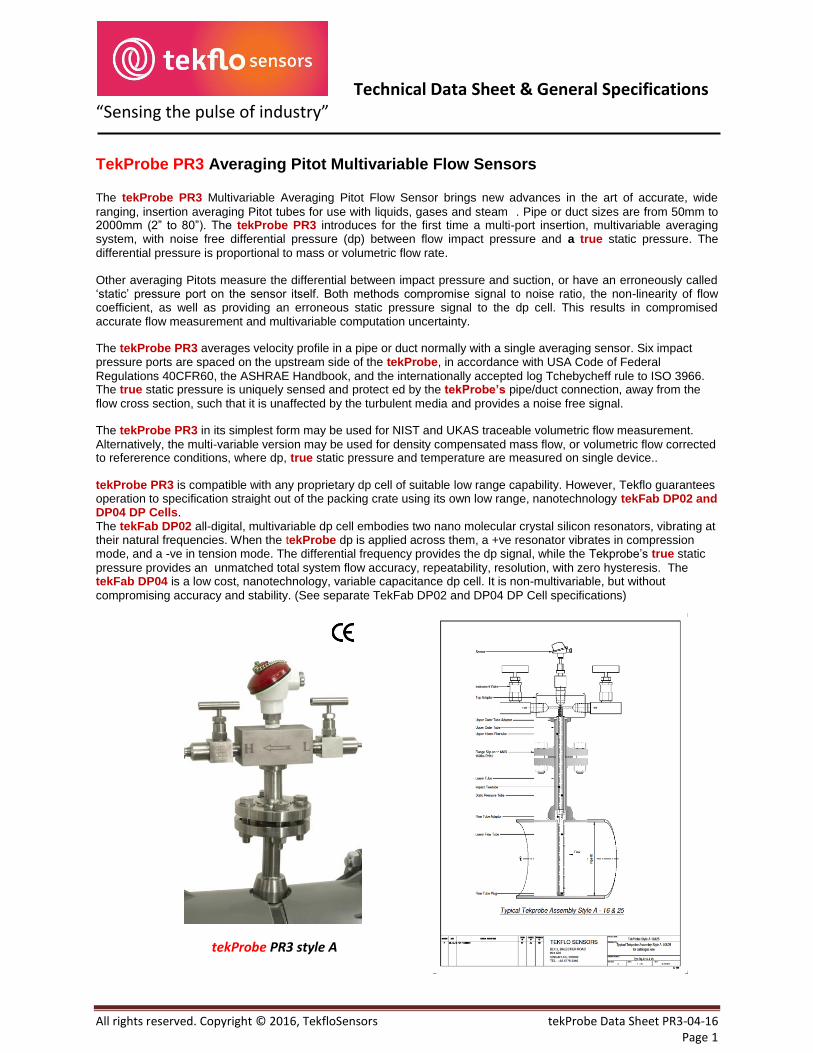
tekProbe PR3 style A

Technical Data Sheet & General Specifications
All rights reserved. Copyright © 2016, TekfloSensors tekProbe Data Sheet PR3-04-16 Page 2
“Sensing the pulse of industry”
tekProbe PR3 Multivariable Flow Sensor Features • The world’s first all-digital Multivariable, true static averaging Pitot, with digital square root extraction • The only averaging Pitot to measure impact pressure and true static pressure to provide uncompromised accurate
volumetric, mass or energy flow sensing • The only averaging Pitot with a linearity to ± 0.5% of reading > 0.5 m/s (1.6 fps) liquids, or gas and steam Reynolds Numbers > 50,000 • The only averaging Pitot offering true static sensing, truly in accordance with Classical Bernoulli Theory • The only averaging Pitot to measure √ (mean dp) to respond accurately to pulsatile flow • The only true profile averaging Pitot with 6 sensing ports in accordance with USA 40CFR60 Code of Federal
Regulations and ASHRAE Handbook and log Tchebycheff rule to ISO 3966 for a single diameter • Complete multi-variable system available, including dp, true static pressure, with tekprobe PR3 protected
temperature sensor, all digital dp cell, steam flow condensate pots, valves, manifolds • USA NIST and CEGB Hams Hall (UK Accreditation Service) traceable, customized Flow Certificate • FM and CSA Explosion Proof Approval to Class 1, Div 1, or FM, CSA and ATEX intrinsic safety • FOUNDATION Fieldbus, RS 485 Modbus and 4-20mA outputs with HART Protocols • tekProbe installation costs > 25% less than 100mm orifice plate, and > 75% less than 500mm orifice
tekProbe PR3 Specification
Flow coefficient non-linearity: ± 0.5% of reading > 0.5 m/s (1.6 fps) liquids, over 4:1 range ± 0.7% of reading over 6: 1 range ±1.0% of reading over 10:1 range Reynolds Numbers > 50,000 for gases and steam. Note: Liquid flow cavitation due to insufficient static pressure, gas adiabatic compression factors, or Mach number effects may cause non-linearity deviation. Consult factory for liquid mean velocities > 3.5 m/s (11 fps), or gas/ steam applications generating > 500mm wg (20” wg).
Repeatability: ± 0.1% of reading
Unrecovered head loss as tekProbe PR3 with 50mm (2”) insert tubes have negligible pressure loss % of differential pressure: in pipes > 1000mm (40”)
Maximum Pressure for tekProbe PR3 with 16mm insert tube diameter: 10 bar max (145 psig) Insertion Under Pressure: tekProbe PR3 with 25mm insert tube diameter: 4 bar max (60 psig) tekProbe PR3 with 50mm insert tube diameter: 1 bar max (15 psig)
Under pressure insertion version not available for steam Maximum Pressure: Without flanges, Styles B and C, max 16 bar g (232 psi g)
With flanges, Style A, according to flange rating max. ANSI 600, PN64 Note: Only flanged versions are available for steam applications. European Pressure PR3 tekProbes conform to the European Pressure Directive PED97/23/EC, Equipment Directive: Article 3, Sound Engineering Practice (SEP), Table 7 Group 2, Table 8 Group 1, and Table 9, Group 2 up to the specified tekProbe PR3 pressures.
Group 1 is for dangerous gases, Group 2 for non-dangerous gases. Maximum Temperature: Without flanges, Style B and C, maximum 150º C (300º F).
With flanges, Style A, according to flange rating max. ANSI 600, PN64 Materials of Construction: AISI 316 stainless steel throughout, except optional brass shut-off valves. tekProbe PR3 Style C with brass shut-off valves are fitted with a brass/bronze
isolation valve and epoxy protected carbon steel pressure chamber. For other materials, consult tekflo or local Authorised distributor.

Technical Data Sheet & General Specifications
All rights reserved. Copyright © 2016, TekfloSensors tekProbe Data Sheet PR3-04-16 Page 3
“Sensing the pulse of industry”
** Minimum Straight Run
* In plane with last upstream bend ** Partially closed valves should be downstream

Technical Data Sheet & General Specifications
All rights reserved. Copyright © 2016, TekfloSensors tekProbe Data Sheet PR3-04-16 Page 4
“Sensing the pulse of industry”
Maximum DP Limits: Steam flow rates producing < 25mm (1”) or > 1500mm (60”) water gauge
dp are not recommended. Pipe sizes may be re-sized accordingly. Maximum recommended dp for gases 500mm (20”) water gauge Liquid flow rates producing < 50 mm (2”) water gauge dp full scale
are not recommended. Pipe sizes may be re-sized accordingly. Liquid viscosities > 300 cP are not recommended. Recommended for Reynold Numbers > 30000
Maximum DP for Various Pipe Sizes: Note: For pipe sizes 1000mm (40”) and greater, where the dp is greater than 100mm (4”) water gauge, a 50mm (2”) insert tube diameter TekProbe PR3 with Lower Support Adaptor (LSA) must be used.

Technical Data Sheet & General Specifications
All rights reserved. Copyright © 2016, TekfloSensors tekProbe Data Sheet PR3-04-16 Page 5
“Sensing the pulse of industry”
tekProbe PR3 Differential Pressure (DP) Basic Formulae The following are basic and approximate formulae provided to determine nominal dp ranges for dp cells. An exact Performance Certificate, traceable to USA National Institute of Standards and Technology (NIST) and UK CEGB Hams Hall with United Kingdom Accreditation Service (UKAS), is provided with each tekProbe PR3. Corrections for
liquid viscosity, gas isotropic exponent, blockage factor, gas specific heat ratio factor, and expansion factors are detailed when relevant. However, these are omitted below for simplicity. Gas reference conditions are to NIST and IEC 60770, ambient temperature to 20ºC (68ºF), 1.013 bar (101.3 kPascals) absolute.
Liquids:
DP mm water gauge = S x 50.94 x (m/s)² DP inches water gauge = S x 0.1864 x (fps)² DP mm water gauge = S x 6384000 x (m³/h)² / D⁴ DP inches water gauge = S x 0.03103 x (gpm)² / (Di)⁴
Gases:
DP mm water gauge = S x 0.05100 x (m/s)² x ρa
DP mm water gauge = S x 6377 x (sm³/h)² x (Pa x Top x ρa / Pop x Ta) / D⁴
DP inches water gauge = S x 0.002989 x (fps)² x ρau
DP inches water gauge = S x 0.02790 x (scfm)² x (Pau x Topu x ρau / ρopu x Tau ) / (Di)⁴ Equivalent rectangular duct diameter De = 2 √ ( H x W) / π )
Steam:
DP mm water gauge = 10850 x (kg/h)² / ρop x D⁴ DP inches water gauge = 0.0003345 x (lb/h)² / ρopu x (Di)⁴
Note: ρop and ρopu are operational densities which are the reciprocal of specific volumes provided in steam tables S tekProbe calibration factor. Approximate values for calculating liquid and gas flow dp: PR3 50mm tekProbes S = 1.65, PR3 25mm tekProbes S = 1.59, PR3 16mm tekProbes S = 1.51
Exact values are provided in USA NIST Traceable Performance Certificates
(m/s) mean velocity metres/second (fps) mean velocity feet/second (m³/h) volumetric flow rate metres/second (gpm) volumetric flow rate US gallons/minute D internal pipe diameter mille metres (Di) internal pipe diameter inches ρa gas density kg/m³ at NIST standard conditions 20º C (293º K), 1.013 bar absolute Note: 1.013 bar = 101.3 kPascals
sm³/h gas flow rate cubic metres/hour at NIST standard conditions 20º C, 1.013 bar absolute Pa absolute pressure 1.013 bar Top operating absolute temperature º K = operating ºC + 273º K Pop operating pressure bar absolute = operating bar gauge + 1.013 Ta absolute temperature at NIST conditions 293º K
ρau gas density lb/ft³ at NIST standard conditions 68º F (528º R), 14.70 psi absolute
scfm gas flow rate foot³/minute at NIST standard conditions 68º F (528º R), 14.70 psi absolute Pau absolute pressure 14.70 psia at NIST standard conditions 68º F (528º R) Topu operating absolute temperature ºR = operating ºF + 460º R Popu operating pressure psi absolute = operating psi gauge +14.70
ρop operational steam density kg/m³ (reciprocal of specific volume given in steam tables)
ρopu operational steam density lb/foot³ (reciprocal of specific volume given in steam tables)
Tau absolute temperature at NIST conditions 528º R De equivalent duct diameter in inches or mm. Take π = 3.142 H height of rectangualar duct inches or mm W width of rectangular duct inches or mm Multiple Tekprobes may be necessary for non-circular ducts. Consult factory

Technical Data Sheet & General Specifications
All rights reserved. Copyright © 2016, TekfloSensors tekProbe Data Sheet PR3-04-16 Page 6
“Sensing the pulse of industry”
tekProbe PR3 NIST Traceable Calibration and Certified UKAS Accredited Facility
The following sample tekProbe PR3 calibration is extracted from a calibration performed at the United Kingdom
Central Electricity Generating Board (CEGB), to whom acknowledgement is given. The CEGB Flow Calibration Facility is at Hams Hall, Coventry University Technology Park, England. This Calibration Facility is certified by the United Kingdom Accreditation Service (UKAS). PR3 tekProbes have been further checked for agreement against a USA National Institute of Standards and
Technology (NIST) traceable magnetic flow meter, having an accuracy to < ± 0.2% of reading. Pipe Size : 12” Schedule 40 carbon steel. Media: Water, tekProbe PR3/25, Serial Number 9992.
Technical Data Sheet & General Specifications
All rights reserved. Copyright © 2016, TekfloSensors tekProbe Data Sheet PR3-04-16 Page 7
“Sensing the pulse of industry”
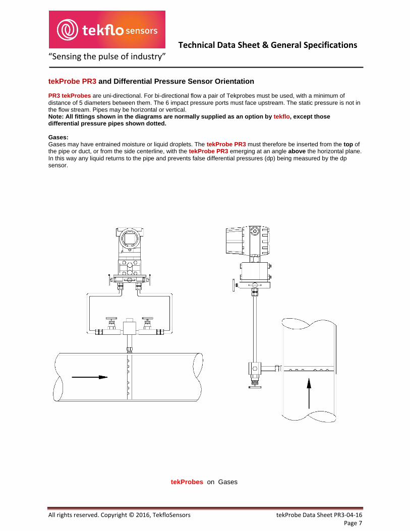
tekProbe PR3 and Differential Pressure Sensor Orientation
PR3 tekProbes are uni-directional. For bi-directional flow a pair of Tekprobes must be used, with a minimum of
distance of 5 diameters between them. The 6 impact pressure ports must face upstream. The static pressure is not in the flow stream. Pipes may be horizontal or vertical. Note: All fittings shown in the diagrams are normally supplied as an option by tekflo, except those differential pressure pipes shown dotted.
Gases: Gases may have entrained moisture or liquid droplets. The tekProbe PR3 must therefore be inserted from the top of the pipe or duct, or from the side centerline, with the tekProbe PR3 emerging at an angle above the horizontal plane.
In this way any liquid returns to the pipe and prevents false differential pressures (dp) being measured by the dp sensor.
tekProbes on Gases
Technical Data Sheet & General Specifications
All rights reserved. Copyright © 2016, TekfloSensors tekProbe Data Sheet PR3-04-16 Page 8
“Sensing the pulse of industry”
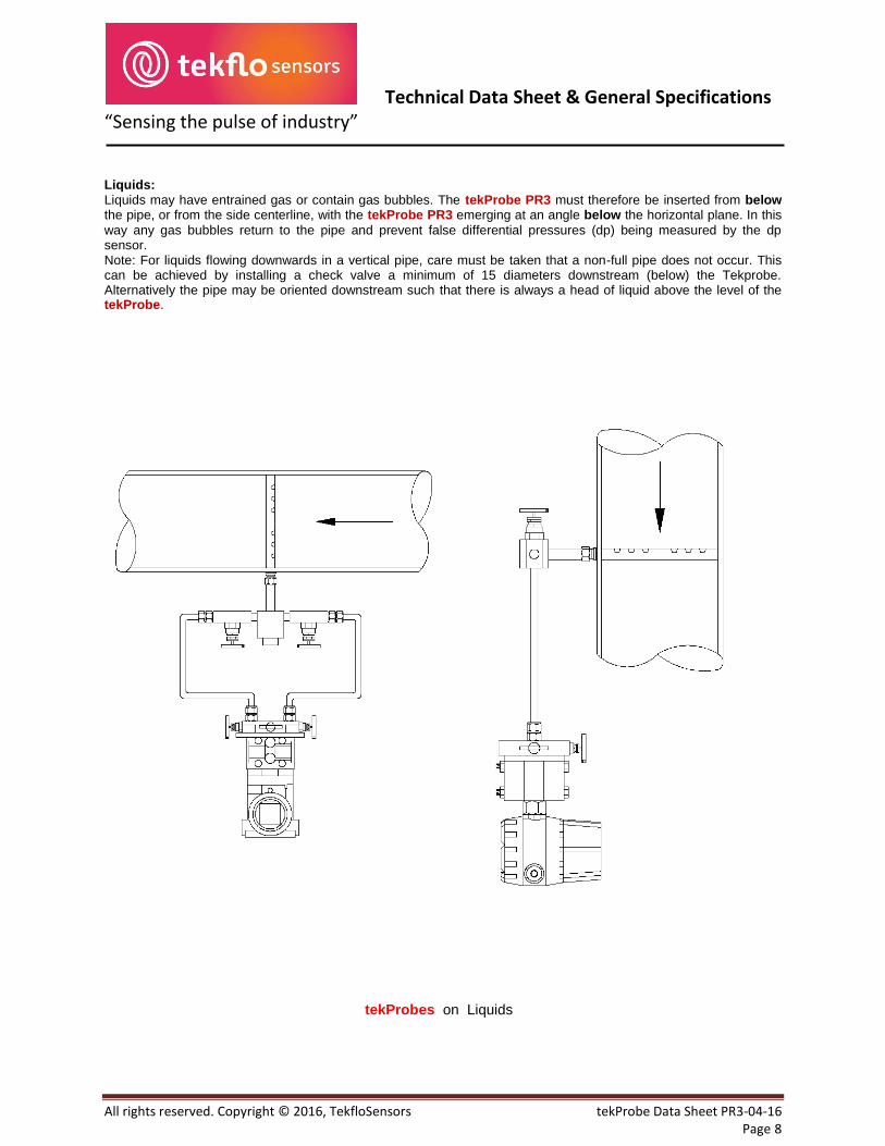
Liquids: Liquids may have entrained gas or contain gas bubbles. The tekProbe PR3 must therefore be inserted from below the pipe, or from the side centerline, with the tekProbe PR3 emerging at an angle below the horizontal plane. In this
way any gas bubbles return to the pipe and prevent false differential pressures (dp) being measured by the dp sensor. Note: For liquids flowing downwards in a vertical pipe, care must be taken that a non-full pipe does not occur. This can be achieved by installing a check valve a minimum of 15 diameters downstream (below) the Tekprobe. Alternatively the pipe may be oriented downstream such that there is always a head of liquid above the level of the tekProbe.
tekProbes on Liquids

Technical Data Sheet & General Specifications
All rights reserved. Copyright © 2016, TekfloSensors tekProbe Data Sheet PR3-04-16 Page 9
“Sensing the pulse of industry”
Saturated or Superheated Steam PR3 tekProbes on steam may be fitted to horizontal or vertical pipes. However, they must always be inserted into the side of the pipe in a horizontal plane, with the differential pressure (dp) sensor below the tekProbe PR3 process connections. PR3 tekpProbes on steam must always be fitted with condensation pots filled with water, such that there are constant and equal heads of water above the dp sensor, shown as dimension h in the diagram. This
prevents false dp being measured by the dp sensor. The condensation pots with all basic fittings shown in the diagram may be provided as an option by tekflo. The dp piping shown in dotted lines are not included.
tekProbes on Steam

Technical Data Sheet & General Specifications
All rights reserved. Copyright © 2016, TekfloSensors tekProbe Data Sheet PR3-04-16 Page 10
“Sensing the pulse of industry”
tekProbe PR3 Style A Dimensional Drawings
Technical Data Sheet & General Specifications
All rights reserved. Copyright © 2016, TekfloSensors tekProbe Data Sheet PR3-04-16 Page 11
“Sensing the pulse of industry”
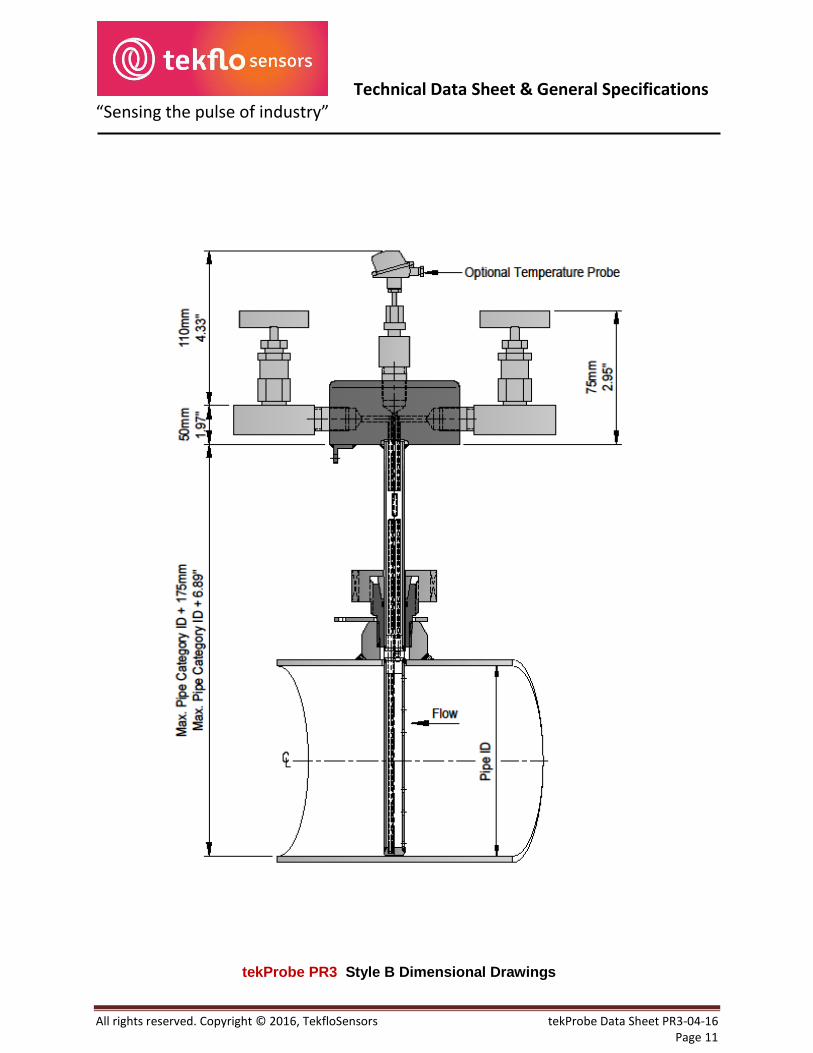
tekProbe PR3 Style B Dimensional Drawings
Technical Data Sheet & General Specifications
All rights reserved. Copyright © 2016, TekfloSensors tekProbe Data Sheet PR3-04-16 Page 12
“Sensing the pulse of industry”
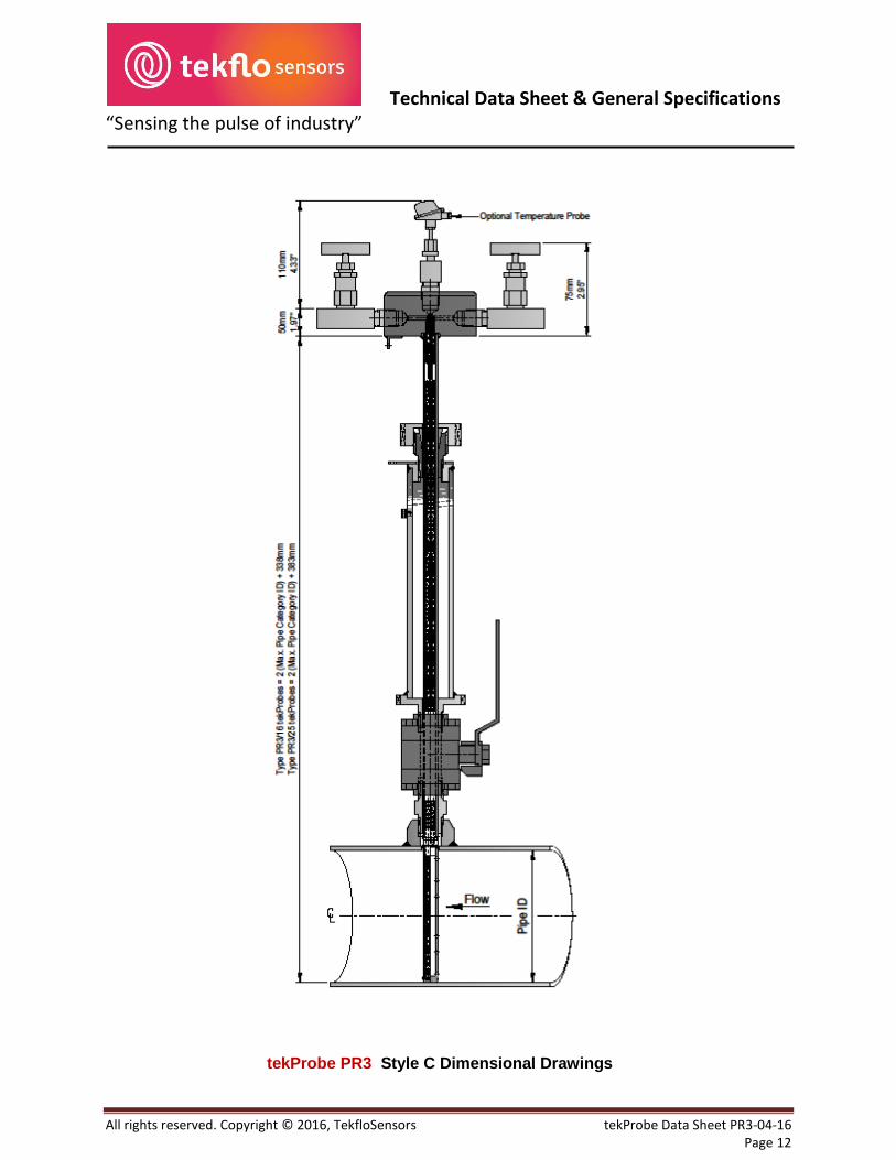
tekProbe PR3 Style C Dimensional Drawings
Technical Data Sheet & General Specifications
All rights reserved. Copyright © 2016, TekfloSensors tekProbe Data Sheet PR3-04-16 Page 13
“Sensing the pulse of industry”
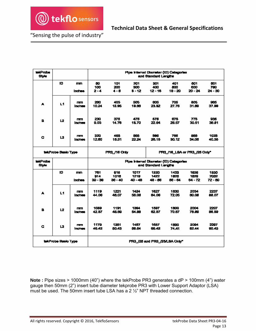
Note : Pipe sizes > 1000mm (40”) where the tekProbe PR3 generates a dP > 100mm (4”) water gauge then 50mm (2”) insert tube diameter tekprobe PR3 with Lower Support Adaptor (LSA) must be used. The 50mm insert tube LSA has a 2 ´” NPT threaded connection.
Technical Data Sheet & General Specifications
All rights reserved. Copyright © 2016, TekfloSensors tekProbe Data Sheet PR3-04-16 Page 14
“Sensing the pulse of industry”
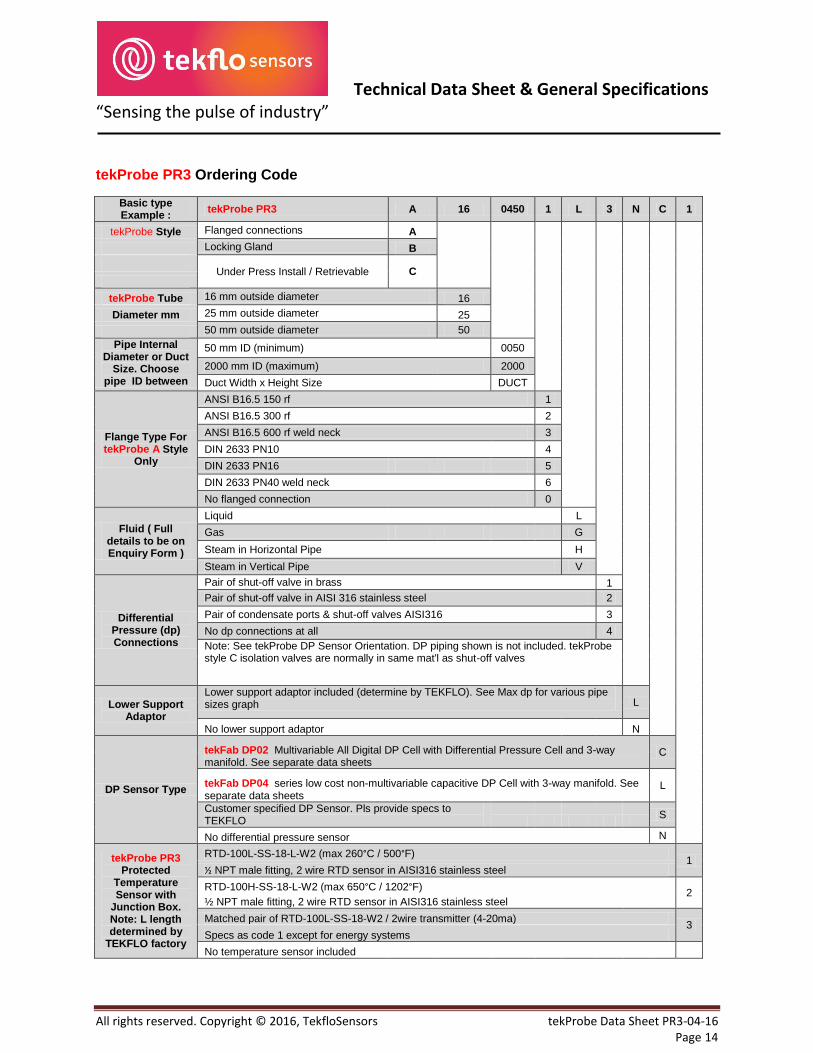
tekProbe PR3 Ordering Code
Basic type Example :
tekProbe PR3 A 16 0450 1 L 3 N C 1
tekProbe Style Flanged connections A Locking Gland B
Under Press Install / Retrievable C
tekProbe Tube 16 mm outside diameter 16 Diameter mm 25 mm outside diameter 25 50 mm outside diameter 50 Pipe Internal
Diameter or Duct Size. Choose
pipe ID between
50 mm ID (minimum) 0050 2000 mm ID (maximum) 2000 Duct Width x Height Size DUCT
Flange Type For tekProbe A Style
Only
ANSI B16.5 150 rf 1 ANSI B16.5 300 rf 2 ANSI B16.5 600 rf weld neck 3 DIN 2633 PN10 4 DIN 2633 PN16 5 DIN 2633 PN40 weld neck 6 No flanged connection 0
Fluid ( Full details to be on Enquiry Form )
Liquid L Gas G Steam in Horizontal Pipe H Steam in Vertical Pipe V
Differential Pressure (dp) Connections
Pair of shut-off valve in brass 1 Pair of shut-off valve in AISI 316 stainless steel 2 Pair of condensate ports & shut-off valves AISI316 3 No dp connections at all 4 Note: See tekProbe DP Sensor Orientation. DP piping shown is not included. tekProbe
style C isolation valves are normally in same mat'l as shut-off valves
Lower Support Adaptor
Lower support adaptor included (determine by TEKFLO). See Max dp for various pipe sizes graph L
No lower support adaptor N
DP Sensor Type
tekFab DP02 Multivariable All Digital DP Cell with Differential Pressure Cell and 3-way manifold. See separate data sheets
C
tekFab DP04 series low cost non-multivariable capacitive DP Cell with 3-way manifold. See separate data sheets
L
Customer specified DP Sensor. Pls provide specs to
TEKFLO S
No differential pressure sensor N
tekProbe PR3
Protected Temperature Sensor with
Junction Box. Note: L length determined by
TEKFLO factory
RTD-100L-SS-18-L-W2 (max 260°C / 500°F) 1
½ NPT male fitting, 2 wire RTD sensor in AISI316 stainless steel
RTD-100H-SS-18-L-W2 (max 650°C / 1202°F) 2
½ NPT male fitting, 2 wire RTD sensor in AISI316 stainless steel Matched pair of RTD-100L-SS-18-W2 / 2wire transmitter (4-20ma)
3 Specs as code 1 except for energy systems No temperature sensor included
Technical Data Sheet & General Specifications
All rights reserved. Copyright © 2016, TekfloSensors tekProbe Data Sheet PR3-04-16 Page 15
“Sensing the pulse of industry”
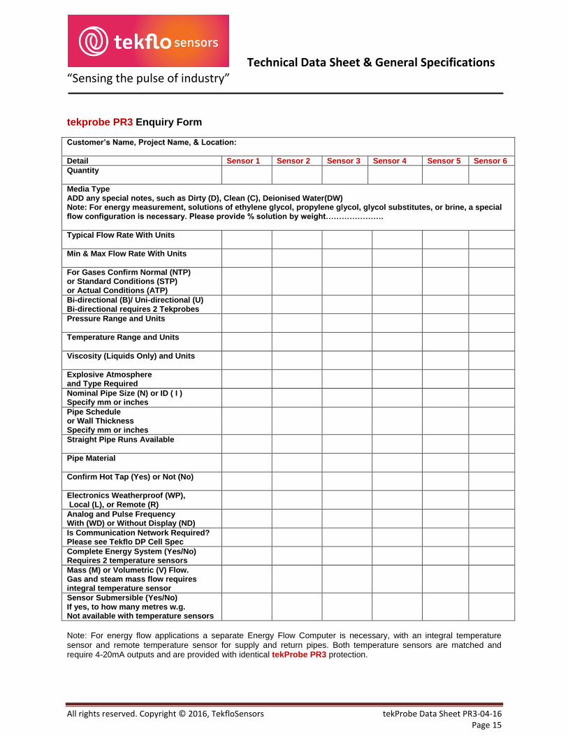
tekprobe PR3 Enquiry Form
Customer’s Name, Project Name, & Location:
Detail Sensor 1 Sensor 2 Sensor 3 Sensor 4 Sensor 5 Sensor 6
Quantity
Media Type ADD any special notes, such as Dirty (D), Clean (C), Deionised Water(DW) Note: For energy measurement, solutions of ethylene glycol, propylene glycol, glycol substitutes, or brine, a special flow configuration is necessary. Please provide % solution by weight………………….
Typical Flow Rate With Units
Min & Max Flow Rate With Units
For Gases Confirm Normal (NTP) or Standard Conditions (STP) or Actual Conditions (ATP)
Bi-directional (B)/ Uni-directional (U) Bi-directional requires 2 Tekprobes
Pressure Range and Units
Temperature Range and Units
Viscosity (Liquids Only) and Units
Explosive Atmosphere and Type Required
Nominal Pipe Size (N) or ID ( I ) Specify mm or inches
Pipe Schedule or Wall Thickness Specify mm or inches
Straight Pipe Runs Available
Pipe Material
Confirm Hot Tap (Yes) or Not (No)
Electronics Weatherproof (WP), Local (L), or Remote (R)
Analog and Pulse Frequency With (WD) or Without Display (ND)
Is Communication Network Required? Please see Tekflo DP Cell Spec
Complete Energy System (Yes/No) Requires 2 temperature sensors
Mass (M) or Volumetric (V) Flow. Gas and steam mass flow requires integral temperature sensor
Sensor Submersible (Yes/No) If yes, to how many metres w.g. Not available with temperature sensors
Note: For energy flow applications a separate Energy Flow Computer is necessary, with an integral temperature sensor and remote temperature sensor for supply and return pipes. Both temperature sensors are matched and require 4-20mA outputs and are provided with identical tekProbe PR3 protection.

Technical Data Sheet & General Specifications
All rights reserved. Copyright © 2016, TekfloSensors tekProbe Data Sheet PR3-04-16 Page 16
“Sensing the pulse of industry”
tekflo sensors®
Factory & Flow Laboratories: Sales and Service: [email protected] Block 2, #04 – 685 Emergency 24-Hour Service: +65 (0) 882 692 768 Balestier Road Website: www.tekflosensors.com Singapore 320002 Phone : +65 (0) 67753340