technical data sheet opus a3 eco full - topcon · pdf file · 2018-02-05technical...
TRANSCRIPT

Industriestraße 7 . 65366 Geisenheim . Germanywww.topcon-electronics.de . [email protected]
Technical Data Sheet OPUS A3 ECO Full
17.01.2018Errors and technical changes excepted

Industriestraße 7 . 65366 Geisenheim . Germanywww.topcon-electronics.de . [email protected]
1 Notes and Warnings
2 General Information
Attention!This description is not a substitution for the con-cerned product’s documentation. Please do read the documentation including the manuals care-fully before dealing with this product. If the safety instructions in the documentation are not followed dangerous situation can occur that can result in damages, injuries and/or death by high voltage or wrong handling. In case you do not have the correct documentation you can order it by con-tacting [email protected]. Only properly trained personnel with the correct qualification are allowed to handle the device.
Attention!Do not open the housing to avoid danger to high voltages. Before touching the electric assemblies make sure that the electricity is switched off com- pletely. If the front pane is broken the device needs to be taken out of service due to risk of injury. If per-ceivable damages on the device exist that can com- promise the functionality, it must be taken out of service due to the danger of malfunctions. These particularly include damages to the LCD display, damages to the keyboard, damages that compro-mise the protection level and damages to the en- coder knobs.
Please note:All content is subject to change without notice. Errors and omissions excepted.
Mounting and Handling 1. Do not use the cable as a handle to carry the device.2. Mounting in clean working environment only. Dust and oil can harm the electric contacts and compromise the functionality.3. Do not mount the device under the use of vio- lence because it can cause damage.4. The device must be mounted by trained per- sonnel only into especially designed and tested systems.5. The device must not be opened or disassembled.6. The device is to be cleaned with a moist fuzz free cotton cloth. If necessary a mild cleaning agent can be used. Do not use acid or abrasive cleaning agents.7. The device is to be stored in a cool and dry environment and to be protected against sun shine.8. If the environmental temperature is beneath 10°C the reaction time of the display increases.
Order Numbers This documentation is valid for OPUS A3 ordernumbers as follows:
The neutral versions (N) will substitute the portrait (P) and landscape (L) versions.
OPUS Projektor CoDeSys ISO-VT
OPUSA3EN1CANF000 OPUSA3EN1CDSF000 OPUSA3EN1ISOF000

Industriestraße 7 . 65366 Geisenheim . Germanywww.topcon-electronics.de . [email protected]
Dimensions
Housing Plastic housing, colored light grey (RAL 7035) with black rubber frame.
Mounting • Landscapeorportrait• Standalone• In-dash

Industriestraße 7 . 65366 Geisenheim . Germanywww.topcon-electronics.de . [email protected]
3 Display
4 Input Devices
5 Electronics
Type: TFT Color Graphic LCD with LED backlightSize: 4.3”, 95 mm (W) x 53 mm (H)Resolution: 480 x 272 px (WQVGA), 15:9
Colors: 16.7 Mio.Brightness: typ. 400 cd/m²Contrast Ratio: typ. 400:1
Touch Analog resistive
Indicators and Sensors • Lightsensor • 1Multicolor-LED
Processor platform CPU: Freescale I.MX35®, 532 MHzMass storage: 1 GByte (approx. 900 MB for customer use)RAM: 256 MByteRTC: Buffered by battery
Buzzer • 60dB(A)in30cmdistance • Lifetimemin.1000h
Current consumption (without external load), max.
Power supplySystem supplied through terminal 30 (battery +, see pinout) and 31 (battery -, see pinout). Terminal 15 (ignition) to be used to switch on/off.Operating voltage range: 9 … 36 V DCShort circuit protection.Over-voltage protection up to 48V for max. 2 minutes. Inverse polarity protection up to -48 V DC for max. 5 minutes.
Power Mode
On Low-power Sleep Off
Current at 13,5 V DC
430 mA160 mA 90 mA < 3 mA
Current at 27 V 240 mA 90 mA 55 mA < 3 mA
Industriestraße 7 . 65366 Geisenheim . Germanywww.topcon-electronics.de . [email protected]
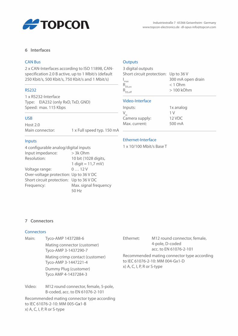
Connectors Main: Tyco-AMP 1437288-6 Mating connector (customer) Tyco-AMP 3-1437290-7 Mating crimp contact (customer) Tyco-AMP 3-1447221-4 Dummy Plug (customer) Tyco AMP 4-1437284-3
Video: M12 round connector, female, 5-pole, B-coded, acc. to EN 61076-2-101Recommended mating connector type according to IEC 61076-2-10: MM 005-Gx1-Bx) A, C, I, P, R or S-type
7 Connectors
Ethernet: M12 round connector, female, 4-pole, D-coded acc. to EN 61076-2-101Recommended mating connector type according to IEC 61076-2-10: MM 004-Gx1-Dx) A, C, I, P, R or S-type
6 Interfaces
CAN Bus 2 x CAN-Interfaces according to ISO 11898, CAN-specification 2.0 B active, up to 1 Mbit/s (default 250 Kbit/s, 500 Kbit/s, 750 Kbit/s and 1 Mbit/s)
RS232 1 x RS232-InterfaceType: EIA232 (only RxD, TxD, GND)Speed: max. 115 Kbps
USB Host 2.0Main connector: 1 x Full speed typ. 150 mA
Inputs 4 configurable analog/digital inputsInput impedance: > 3k OhmResolution: 10 bit (1028 digits, 1 digit = 11,7 mV)Voltage range: 0 … 12 VOver-voltage protection: Up to 36 V DCShort circuit protection: Up to 36 V DCFrequency: Max. signal frequency 50 Hz
Outputs 3 digital outputsShort circuit protection: Up to 36 VImax 300 mA open drainRDS,on < 1 OhmRDS,off > 100 kOhm
Video-InterfaceInputs: 1x analogVss 1 V Camera supply: 12 VDCMax. current: 500 mA
Ethernet-Interface 1 x 10/100 Mbit/s Base T

Industriestraße 7 . 65366 Geisenheim . Germanywww.topcon-electronics.de . [email protected]
9 Testing and Verification
Operating System Linux Kernel 3.0.0 or higher
Application Programming • OPUSProjektor • Codesys-Tools(3.X) • ISO-VT • C/C++
CE-Compliance EU Directive 2014/30/EU (EMC) according to• EN 12895: Industrial Trucks – Electromagnetic compatibility• EN 13309: Construction machinery – Electro- magnetic compatibility of machines with inter- nal electrical power supply• EN ISO 14982: Agricultural and forestry machi- nery - Electromagnetic compatibility - Test methods and acceptance criteria
E1 - Type approvalEU Directive ECE R 10.4
Protection Level (IP Code) IP 65 and IP 66 according to ISO 20653: Road Vehic-les – Degrees of protection (IP-Code) – Protection of electrical equipment against foreign objects, water and access
Electrical 12 and 24V-Systems according to ISO 16750-2: Road Vehicles – Environmental conditions and testing for electrical and electronic equipment – Electrical loads• ISO 15003: Agricultural Engineering – Electrical and electronic equipment – Testing resistance to environmental conditions
8 Software
Mechanical • ISO 16750-3: Road Vehicles – Environmental conditions and testing for electrical and electronic equipment – Mechanical loads, Code L• ISO 15003: Agricultural Engineering – Electrical and electronic equipment – Testing resistance to environmental conditions •MechanicalShock:Level2 • RandomVibration:Level2 • SinusoidalVibration:Level2
Climate• ISO 16750-4: Road Vehicles – Environmental con- ditions and testing for electrical and electronic equipment – Climatic Loads • Operating Temperature Range: -30 … +65°C • StorageTemperatureRange:-40…+85°C• ISO 15003: Agricultural Engineering – Electrical and electronic equipment – Testing resistance to environmental conditions

Industriestraße 7 . 65366 Geisenheim . Germanywww.topcon-electronics.de . [email protected]
10 Pinout
Main connector pinout
View on rear side of the A3
1 7
814 19
13
20 26
Pin. No.
1 2 3 4 5 6 7 8 91011121314151617181920212223242526
Assignment
VCCIgnition InputGNDCarGNDn. c.n. c.n. c.CAN1HCAN1LCAN2HCAN2LUSB_VCCUSB_GNDUSB_D-USB_D+RS232 RxDRS232 TxDRS232 GNDA/DI3A/DI1A/DI2A/DI4SERV_ENDO3DO1DO2
Description
supply voltage +; terminal 30ignition input; terminal 15supply voltage - ;terminal 31Car GNDNot connectedNot connectedNot connectedCAN 1 highCAN 1 lowCAN 2 highCAN 2 lowUSB +5V supplyUSB supply GNDUSB Data -USB Data +RS232 receive dataRS232 transmit dataRS232 GNDanalog/digital input 3analog/digital input 1analog/digital input 2analog/digital input 4service enabledigital output 3digital output 1digital output 2
Industriestraße 7 . 65366 Geisenheim . Germanywww.topcon-electronics.de . [email protected]
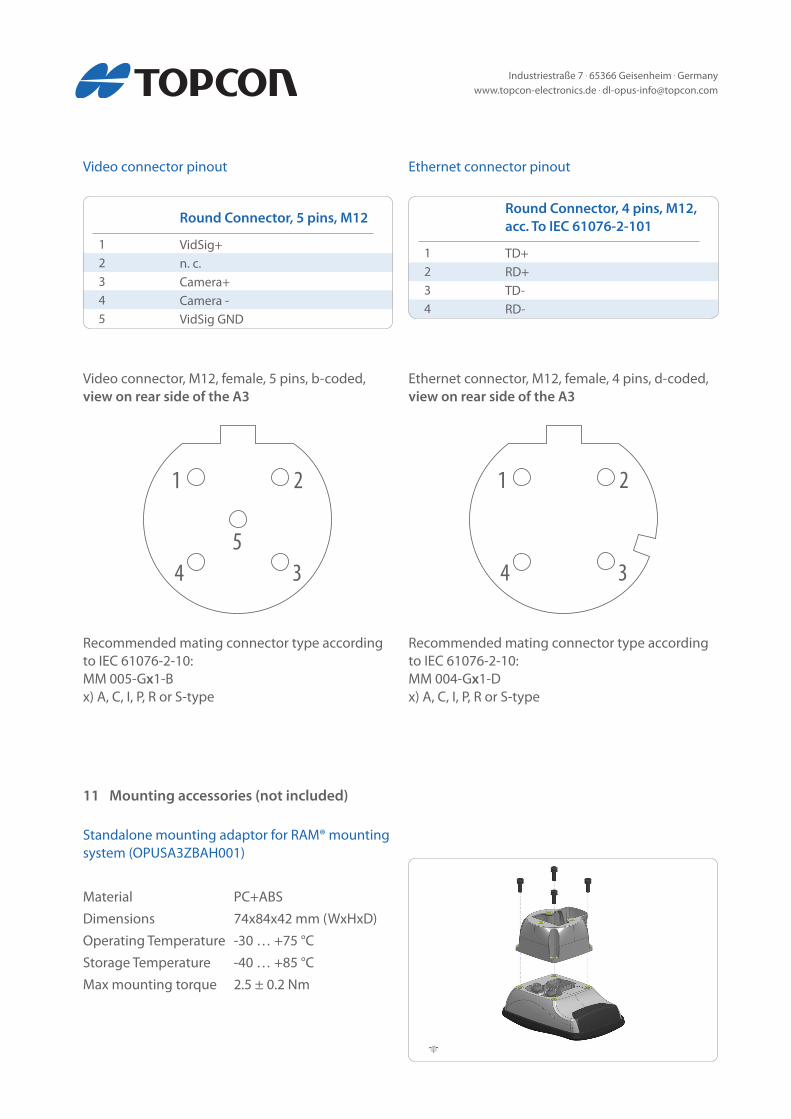
Video connector pinout Ethernet connector pinout
Video connector, M12, female, 5 pins, b-coded,view on rear side of the A3
Ethernet connector, M12, female, 4 pins, d-coded,view on rear side of the A3
Recommended mating connector type according to IEC 61076-2-10:MM 005-Gx1-Bx) A, C, I, P, R or S-type
Recommended mating connector type according to IEC 61076-2-10:MM 004-Gx1-Dx) A, C, I, P, R or S-type
1 2
345
1 2
34
12345
Round Connector, 5 pins, M12
VidSig+n. c.Camera+Camera -VidSig GND
1234
Round Connector, 4 pins, M12, acc. To IEC 61076-2-101
TD+RD+TD-RD-
11 Mounting accessories (not included)
Standalone mounting adaptor for RAM® mounting system (OPUSA3ZBAH001)
Material PC+ABSDimensions 74x84x42 mm (WxHxD)Operating Temperature -30 … +75 °CStorage Temperature -40 … +85 °CMax mounting torque 2.5 ± 0.2 Nm
Industriestraße 7 . 65366 Geisenheim . Germanywww.topcon-electronics.de . [email protected]
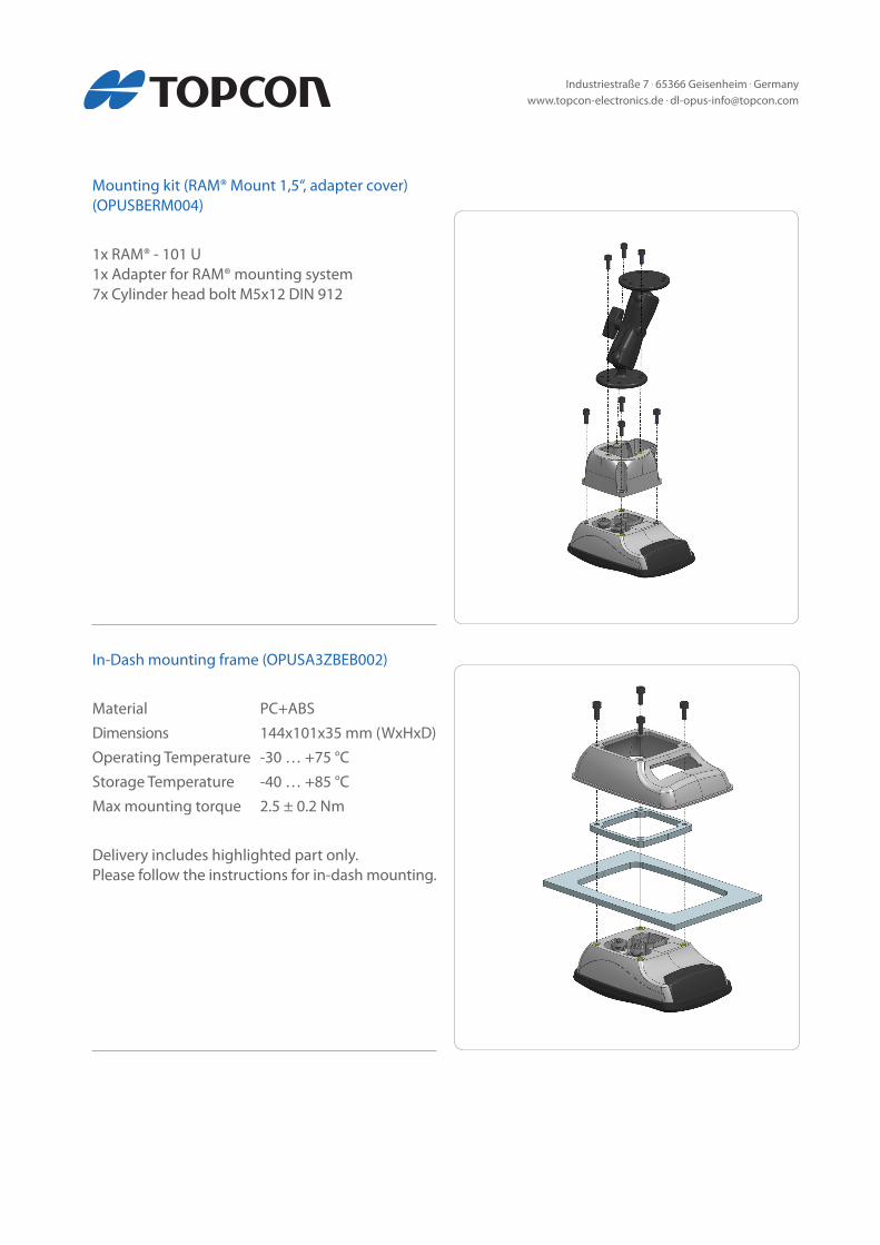
Mounting kit (RAM® Mount 1,5‘‘, adapter cover) (OPUSBERM004)
1x RAM® - 101 U1x Adapter for RAM® mounting system7x Cylinder head bolt M5x12 DIN 912
In-Dash mounting frame (OPUSA3ZBEB002)
Material PC+ABSDimensions 144x101x35 mm (WxHxD)Operating Temperature -30 … +75 °CStorage Temperature -40 … +85 °CMax mounting torque 2.5 ± 0.2 Nm
Delivery includes highlighted part only.Please follow the instructions for in-dash mounting.
Industriestraße 7 . 65366 Geisenheim . Germanywww.topcon-electronics.de . [email protected]
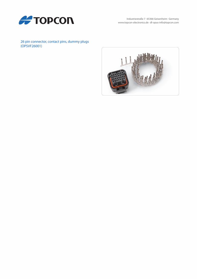
26 pin connector, contact pins, dummy plugs(OPSVF26001)