technical description - addi-data · technical description . msx-exxxx intelligent ethernet system...
TRANSCRIPT

DIN EN ISO 9001:2015 certified Edition: 02.08-05/2018
TECHNICAL
DESCRIPTION MSX-Exxxx Intelligent Ethernet system

Product information This manual contains the technical installation and important instructions for correct commissioning and usage, as well as production information according to the current state before printing. The content of this manual and the technical product data may be changed without prior notice. ADDI-DATA GmbH reserves the right to make changes to the technical data and the materials included herein.
Warranty and liability The user is not authorised to make changes to the product beyond the intended use, or to interfere with the product in any other way. ADDI-DATA shall not be liable for obvious printing and phrasing errors. In addition, ADDI DATA, if legally permissible, shall not be liable for personal injury or damage to materials caused by improper installation and/or commissioning of the product by the user or improper use, for example, if the product is operated despite faulty safety and protection devices, or if notes in the operating instructions regarding transport, storage, installation, commissioning, operation, thresholds, etc. are not taken into consideration. Liability is further excluded if the operator changes the product or the source code files without authorisation and/or if the operator is guilty of not monitoring the permanent operational capability of working parts and this has led to damage.
Copyright This manual, which is intended for the operator and its staff only, is protected by copyright. Duplication of the information contained in the operating instructions and of any other product information, or disclosure of this information for use by third parties, is not permitted, unless this right has been granted by the product licence issued. Non-compliance with this could lead to civil and criminal proceedings.
ADDI-DATA software product licence Please read this licence carefully before using the standard software. The customer is only granted the right to use this software if he/she agrees with the conditions of this licence. The software may only be used to set up the ADDI-DATA products. Reproduction of the software is forbidden (except for back-up and for exchange of faulty data carriers). Disassembly, decompilation, decryption and reverse engineering of the software are forbidden. This licence and the software may be transferred to a third party if this party has acquired a product by purchase, has agreed to all the conditions in this licence contract and the original owner does not keep any copies of the software.
Trademarks • ADDI-DATA, APCI-1500, MSX-Box and MSX-E are registered trademarks of ADDI-DATA GmbH. • Turbo Pascal, Delphi, Borland C, Borland C++ are registered trademarks of Borland Software
Corporation. • Microsoft .NET, Microsoft C, Visual C++, MS-DOS, Windows XP, Windows 7, Windows 8,
Windows 10, Windows Server 2000, Windows Server 2003, Windows Embedded and Internet Explorer are registered trademarks of Microsoft Corporation.
• Linux is a registered trademark of Linus Torvalds. • LabVIEW, LabWindows/CVI, DASYLab, DIAdem are registered trademarks of National Instruments
Corporation. • CompactPCI is a registered trademark of PCI Industrial Computer Manufacturers Group. • VxWorks is a registered trademark of Wind River Systems, Inc. • RTX is a registered trademark of IntervalZero. • Mozilla Firefox is a registered trademark of Mozilla Foundation. • SIMATIC S7 is a registered trademark of Siemens AG.
www.addi-data.com 2

Warning!
The following risks result from the improper implementation of the Ethernet system and from use contrary to the regulations:
Personal injury
Damage to the Ethernet system, the PC and peripherals
Pollution of the environment.
Protect yourself, others and the environment!
Read the safety precautions (yellow leaflet) carefully!
If this leaflet is not enclosed with the documentation, please contact us and ask for it.
Observe the instructions of this manual!
Make sure that you do not forget or skip any step! We are not liable for damages resulting from the wrong use of the Ethernet system.
Pay attention to the following symbols:
NOTICE! Designates hints and other useful information.
NOTICE! Designates a possibly dangerous situation. If the instructions are ignored, the Ethernet system, the PC and/or peripherals may be destroyed.
WARNING! Designates a possibly dangerous situation. If the instructions are ignored, the Ethernet system, the PC and/or peripherals may be destroyed and persons may be endangered.
www.addi-data.com 3
Contents MSX-Exxxx
Contents Warning! ...........................................................................................................................................3 Chapter overview.............................................................................................................................8 1 Mounting and connection....................................................................................................9 1.1 Commissioning the Ethernet system ...................................................................................................9 1.2 Fixing the Ethernet system.................................................................................................................11 1.2.1 DIN rail mounting ...............................................................................................................................11 1.2.2 Angle bracket mounting ....................................................................................................................12 1.3 Pin assignment ....................................................................................................................................14 1.3.1 Ethernet...............................................................................................................................................15 1.3.2 Trigger/Synchro...................................................................................................................................16 1.3.3 Power supply .......................................................................................................................................17 1.4 Connecting the peripherals................................................................................................................18 1.4.1 Ethernet...............................................................................................................................................18 1.4.2 Trigger/Synchro...................................................................................................................................19 1.4.3 Power supply .......................................................................................................................................19 1.4.4 Sensors or actuators............................................................................................................................19 1.5 Connecting several Ethernet systems (cascading) ............................................................................20 1.6 LED display ..........................................................................................................................................21 1.6.1 Overview..............................................................................................................................................21 1.6.2 “Status” LED........................................................................................................................................22 2 Software tool “ConfigTools” .............................................................................................24 2.1 First steps .............................................................................................................................................24 2.2 Main window structure ......................................................................................................................25 2.2.1 Menu bar .............................................................................................................................................25 2.2.2 ConfigTools Explorer ..........................................................................................................................26 2.2.3 Actions .................................................................................................................................................27 3 Function description: General functions...........................................................................28 3.1 Hardware trigger ................................................................................................................................28 3.2 Synchronisation...................................................................................................................................29 3.2.1 Master and slaves................................................................................................................................29 3.3 Time stamp..........................................................................................................................................30 3.3.1 Time and date .....................................................................................................................................30 3.4 Temperature monitoring ...................................................................................................................30 3.5 Customer key (security feature).........................................................................................................30 4 Web interface: Quick access to the MSX-E system ...........................................................32 4.1 Login ....................................................................................................................................................32 4.2 Navigation ...........................................................................................................................................33 4.3 “System”..............................................................................................................................................34 4.3.1 Menu item or tab “Information” ......................................................................................................34 4.3.2 Menu item or tab “Diagnosis”...........................................................................................................35 4.3.3 Menu item or tab “Security” .............................................................................................................40 4.3.4 Menu item or tab “Shutdown” or menu item “Reboot” ................................................................45 4.4 “Network”...........................................................................................................................................46 4.4.1 Menu item or tab “Diagnosis”...........................................................................................................46 4.4.2 Menu item or tab “Configuration”...................................................................................................47 4.4.3 “Advanced” network mode or tab....................................................................................................48 4.4.4 Menu item or tab “NTP client”..........................................................................................................51 4.5 “I/O Configuration” or “Trigger/Synchronisation” (new) ...............................................................51 4.5.1 Menu item or tab “Synchro timer” ...................................................................................................52 4.5.2 Menu item or tab “Hardware trigger” .............................................................................................52 4.5.3 “Master/Slave” tab (new)...................................................................................................................52 4.5.4 “Configuration management” section .............................................................................................53
www.addi-data.com 4

Contents MSX-Exxxx
4.5.5 “Autostart” section (Automatic configuration start).......................................................................53 4.6 “Development Mode”........................................................................................................................54 4.7 Menu item “File Manager” (new) .....................................................................................................54 4.8 “Data server” ......................................................................................................................................55 4.8.1 Network protocol................................................................................................................................55 4.8.2 “Blocking (TCP/IP) transfer” section or tab.......................................................................................56 4.8.3 “Data caching” section or tab ...........................................................................................................57 4.8.4 Save and Restart..................................................................................................................................60 4.9 “Modbus server”.................................................................................................................................60 4.10 Menu item “Extras” (new) .................................................................................................................61 5 Software ..............................................................................................................................62 5.1 MSX-E system interface ......................................................................................................................62 5.2 Access via SOAP/web service ..............................................................................................................63 5.2.1 SOAP definition...................................................................................................................................63 5.2.2 SOAP functions....................................................................................................................................63 5.3 Access via Open Modbus (for PLC).....................................................................................................63 5.4 Data server ..........................................................................................................................................64 5.5 Event server .........................................................................................................................................64 5.5.1 Packet format......................................................................................................................................64 5.5.2 Time stamp format .............................................................................................................................64 6 Return or disposal...............................................................................................................65 6.1 Return ..................................................................................................................................................65 6.2 Disposal of ADDI-DATA waste equipment........................................................................................66 7 Appendix .............................................................................................................................67 7.1 Glossary................................................................................................................................................67 7.2 Index ....................................................................................................................................................69 8 Contact and support ...........................................................................................................70
Figures
Fig. 1-1: Commissioning (overview) .............................................................................................................9 Fig. 1-2: Type label ......................................................................................................................................10 Fig. 1-3: Fastening clips ...............................................................................................................................11 Fig. 1-4: Brackets pointing outwards .........................................................................................................12 Fig. 1-5: Brackets pointing inwards............................................................................................................12 Fig. 1-6: Angle bracket mounting ..............................................................................................................13 Fig. 1-7: Mounting set: Seal and screw (short) ..........................................................................................13 Fig. 1-8: Mounting set: Original screw, seal and screw (long) .................................................................13 Fig. 1-9: Connectors.....................................................................................................................................14 Fig. 1-10: Connect peripherals......................................................................................................................18 Fig. 1-11: Connect sensors or actuators (example) .....................................................................................19 Fig. 1-12: Cascading.......................................................................................................................................20 Fig. 2-1: ConfigTools: Scan MSX-E systems ................................................................................................24 Fig. 2-2: ConfigTools: Main window..........................................................................................................25 Fig. 2-3: ConfigTools: MSX-E search...........................................................................................................26 Fig. 2-4: ConfigTools: Action buttons ........................................................................................................27 Fig. 3-1: Example of a trigger.....................................................................................................................29 Fig. 4-1: MSX-E web interface: Login window ..........................................................................................32 Fig. 4-2: MSX-E web interface: Homepage................................................................................................33 Fig. 4-3: MSX-E web interface: Homepage (new) .....................................................................................34 Fig. 4-4: MSX-E web interface: System/Diagnosis .....................................................................................35 Fig. 4-5: MSX-E web interface: System/Diagnosis (new)...........................................................................36
www.addi-data.com 5
Contents MSX-Exxxx
Fig. 4-6: Diagnosis: Subsystem state...........................................................................................................36 Fig. 4-7: Subsystems & states ......................................................................................................................37 Fig. 4-8 Diagnosis: I/O high precision clock ..............................................................................................37 Fig. 4-9: Diagnosis: I/O high precision clock (new)....................................................................................37 Fig. 4-10: Diagnosis: Resources.....................................................................................................................38 Fig. 4-11: Diagnosis: Resources (new) ..........................................................................................................38 Fig. 4-12: Diagnosis: Inter-system synchronisation .....................................................................................38 Fig. 4-13: Diagnosis: Inter-system synchronisation (new)...........................................................................39 Fig. 4-14: Diagnosis: Process list ...................................................................................................................39 Fig. 4-15: Diagnosis: Process list (new).........................................................................................................39 Fig. 4-16: Diagnosis: Mounts ........................................................................................................................40 Fig. 4-17: Diagnosis: Mounts (new)..............................................................................................................40 Fig. 4-18: Diagnosis: Kernel parameters ......................................................................................................40 Fig. 4-19: Diagnosis: Kernel parameters (new) ...........................................................................................40 Fig. 4-20: “Security”: Enter new password..................................................................................................41 Fig. 4-21: “Security”: Enter new password (new) .......................................................................................41 Fig. 4-22: “Security”: TLS encryption ...........................................................................................................42 Fig. 4-23: “Security”: Remote call “SetTime()” ...........................................................................................43 Fig. 4-24: “Security”: Remote calls “autoconf/autostart” ..........................................................................43 Fig. 4-25: ”Security”: General system configuration ..................................................................................44 Fig. 4-26: “Security”: Remote commands....................................................................................................45 Fig. 4-27: Shutdown: Action .........................................................................................................................45 Fig. 4-28: Reboot: Action ..............................................................................................................................45 Fig. 4-29: Shutdown: Action (new) ..............................................................................................................46 Fig. 4-30: “Diagnosis”: TCP and UDP ...........................................................................................................46 Fig. 4-31: “Diagnosis”: TCP and UDP (new).................................................................................................47 Fig. 4-32: Configuration: Network configuration.......................................................................................47 Fig. 4-33: Configuration: Network configuration (new) ............................................................................47 Fig. 4-34: Configuration: Syslog (network logging) ...................................................................................48 Fig. 4-35: Configuration: Syslog (network logging) (new).........................................................................48 Fig. 4-36: Advanced network configuration ...............................................................................................49 Fig. 4-37: Advanced network configuration (new).....................................................................................49 Fig. 4-38: DHCP ..............................................................................................................................................49 Fig. 4-39: DHCP (new) ...................................................................................................................................50 Fig. 4-40: /etc/hosts, Sysctl and Eth0 (new)..................................................................................................50 Fig. 4-41: NTP client: Configuration.............................................................................................................51 Fig. 4-42: NTP client: Configuration (new) ..................................................................................................51 Fig. 4-43: Synchro timer: Configuration ......................................................................................................52 Fig. 4-44: Synchro timer: Configuration (new)............................................................................................52 Fig. 4-45: I/O Configuration: Configuration management.........................................................................53 Fig. 4-46: File Manager: Browser (new) .......................................................................................................54 Fig. 4-47: “Data server”: Network protocol ................................................................................................55 Fig. 4-48: “Data server”: Network protocol (new)......................................................................................56 Fig. 4-49: Data server: Blocking (TCP/IP) transfer........................................................................................56 Fig. 4-50: Data server: Blocking (TCP/IP) transfer (new) .............................................................................56 Fig. 4-51: Data server: Data caching ............................................................................................................57 Fig. 4-52: Data server: Data caching (new)..................................................................................................57 Fig. 4-53: Ring buffer ....................................................................................................................................59 Fig. 4-54: Data server: What do you want to do?.......................................................................................60 Fig. 4-55: Extras: Languages (new)...............................................................................................................61 Fig. 5-1: Server overview.............................................................................................................................62 Fig. 5-2: SOAP in the TCP/IP protocol stack ...............................................................................................63 Fig. 6-1: Serial number................................................................................................................................65 Fig. 6-2: Disposal: Label...............................................................................................................................66
www.addi-data.com 6

Contents MSX-Exxxx
www.addi-data.com 7
Tables Table 1-1: Pin assignment: Ethernet ports....................................................................................................15 Table 1-2: Pin assignment: Trigger/Synchro..................................................................................................16 Table 1-3: Trigger/Synchro cables..................................................................................................................16 Table 1-4: Pin assignment: Power supply (input and output) .....................................................................17 Table 1-5: LED display ....................................................................................................................................21 Table 1-6: “Status” LED..................................................................................................................................22 Table 3-1: Temperature monitoring: MSX-Exxxx .........................................................................................30 Table 3-2: Temperature monitoring: MSX-E3700 and MSX-E3701 .............................................................30 Table 3-3: Customer key ................................................................................................................................31 Table 5-1: MSX-E servers ................................................................................................................................62 Table 5-2: Event server: Packet format .........................................................................................................64

Chapter overview MSX-Exxxx
Chapter overview
In this manual, you will find the following information:
Chapter Content
1 Information on mounting the MSX-E system, pin assignments, the connection of peripherals and the system’s LED display
2 Description of the software tool “ConfigTools” (required, for example, to adapt the IP address of the MSX-E system when using the system for the first time)
3 Description of general functions (e.g. Customer Key)
4 Description of the web interface of the MSX-E system
5 Software description: Access over SOAP/web service or Open Modbus (for PLC)
6 Procedure for returning (repairing, etc.) or disposing of the MSX-E system
7 Appendix with glossary and index
8 Contact and support address
www.addi-data.com 8

Mounting and connection MSX-Exxxx
1 Mounting and connection
Risk of injury! Please follow the safety precautions! An improper handling of the Ethernet system may cause property damage and injury.
1.1 Commissioning the Ethernet system
Fig. 1-1: Commissioning (overview)
Discharge any static by touching an earth wire.
Remove the Ethernet system from its protective packaging.
Check the type label on the bottom side of the Ethernet system to know if the system corresponds to your requested version.
www.addi-data.com 9

Mounting and connection MSX-Exxxx
Fig. 1-2: Type label
Serial number
Disposal label Version
Product name
Customisation
Supply voltage
Nominal voltage
Current consumption
The type label contains, for example, the product name including the specific version name, and the serial number of the Ethernet system. In case of queries, these details always have to be kept at hand! For more information on the disposal label, see Chapter 6.2.
NOTICE! Information on cables and other accessories can be found in the accessories list for the MSX-E systems.
www.addi-data.com 10
Mounting and connection MSX-Exxxx
www.addi-data.com 11
1.2 Fixing the Ethernet system
1.2.1 DIN rail mounting
With the mounting set MX-Rail1 (see document “MSX-E Accessories“), you can attach the Ethernet system to a DIN rail.
Risk of injury! If you have already mounted this Ethernet system on a DIN rail and want to transport it in a switch cabinet or in other systems, please ensure that it is adequately secured for transport! The Ethernet system could, for example, fall off the DIN rail, which could cause damage to the Ethernet system and/or other objects or injury of persons.
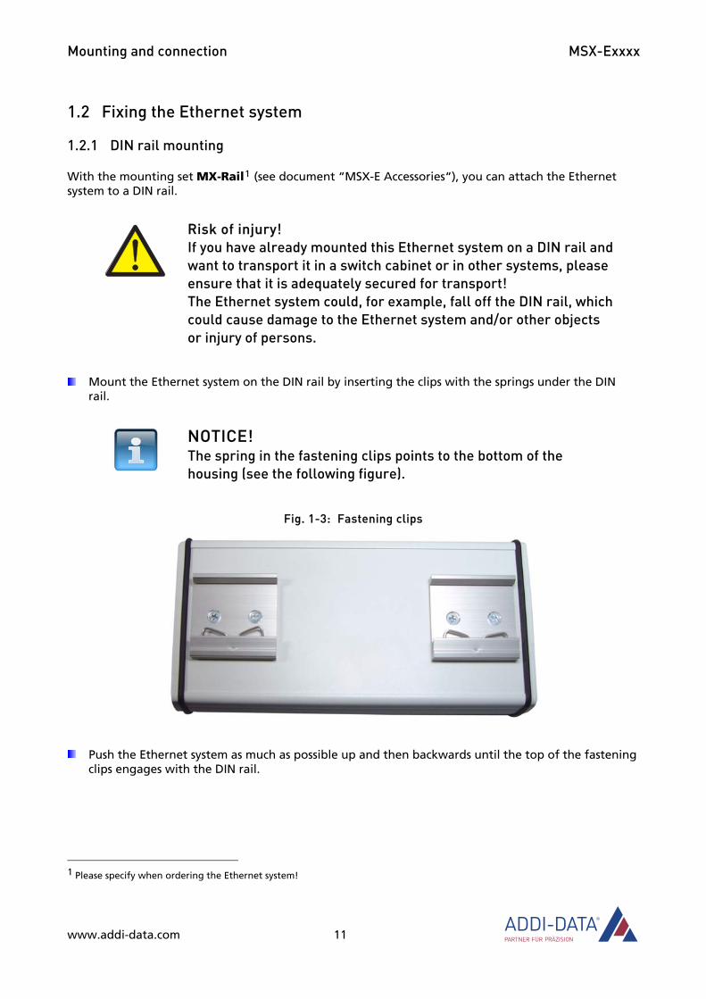
Mount the Ethernet system on the DIN rail by inserting the clips with the springs under the DIN rail.
NOTICE! The spring in the fastening clips points to the bottom of the housing (see the following figure).
Fig. 1-3: Fastening clips
Push the Ethernet system as much as possible up and then backwards until the top of the fastening clips engages with the DIN rail.
1 Please specify when ordering the Ethernet system!
Mounting and connection MSX-Exxxx
1.2.2 Angle bracket mounting
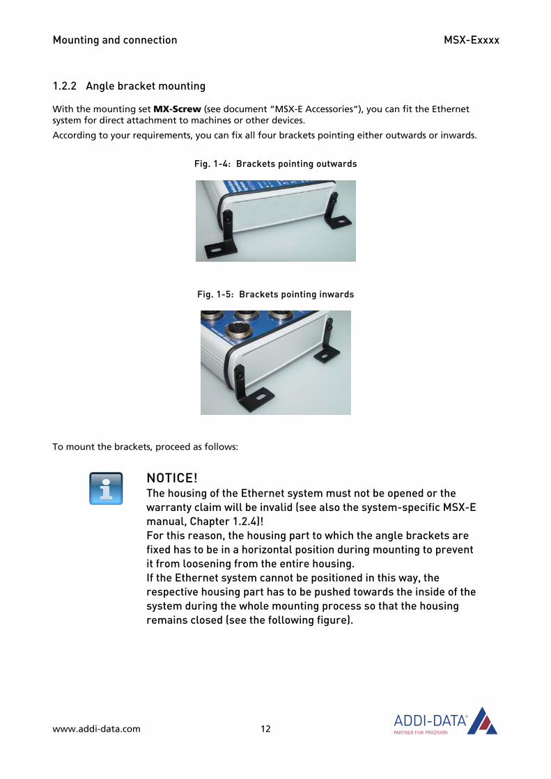
With the mounting set MX-Screw (see document “MSX-E Accessories“), you can fit the Ethernet system for direct attachment to machines or other devices.
According to your requirements, you can fix all four brackets pointing either outwards or inwards.
Fig. 1-4: Brackets pointing outwards
Fig. 1-5: Brackets pointing inwards
To mount the brackets, proceed as follows:
NOTICE! The housing of the Ethernet system must not be opened or the warranty claim will be invalid (see also the system-specific MSX-E manual, Chapter 1.2.4)! For this reason, the housing part to which the angle brackets are fixed has to be in a horizontal position during mounting to prevent it from loosening from the entire housing. If the Ethernet system cannot be positioned in this way, the respective housing part has to be pushed towards the inside of the system during the whole mounting process so that the housing remains closed (see the following figure).
www.addi-data.com 12

Mounting and connection MSX-Exxxx
Fig. 1-6: Angle bracket mounting
Loosen the screws at the side of the Ethernet system.
For the remainder of the mounting process, please use only the short seals and screws from the mounting set.
Fig. 1-7: Mounting set: Seal and screw (short)
The original screw from the MSX-E system and the long seals or screws from the mounting set must not be used any longer.
Fig. 1-8: Mounting set: Original screw, seal and screw (long)
www.addi-data.com 13

Mounting and connection MSX-Exxxx
Place a seal in one of the screw holes.
Place the bracket on the seal.
Fix the bracket with a short screw from the mounting set.
Repeat these steps with the other screw holes.
Once you have mounted the brackets on the Ethernet system, you can attach the system directly to other devices or machines by using other screws.
1.3 Pin assignment
In this chapter, you will find the pin assignments of the connectors for Ethernet, trigger/synchro and the power supply of the Ethernet system MSX-Exxxx.
Fig. 1-9: Connectors
www.addi-data.com 14
Mounting and connection MSX-Exxxx
1.3.1 Ethernet
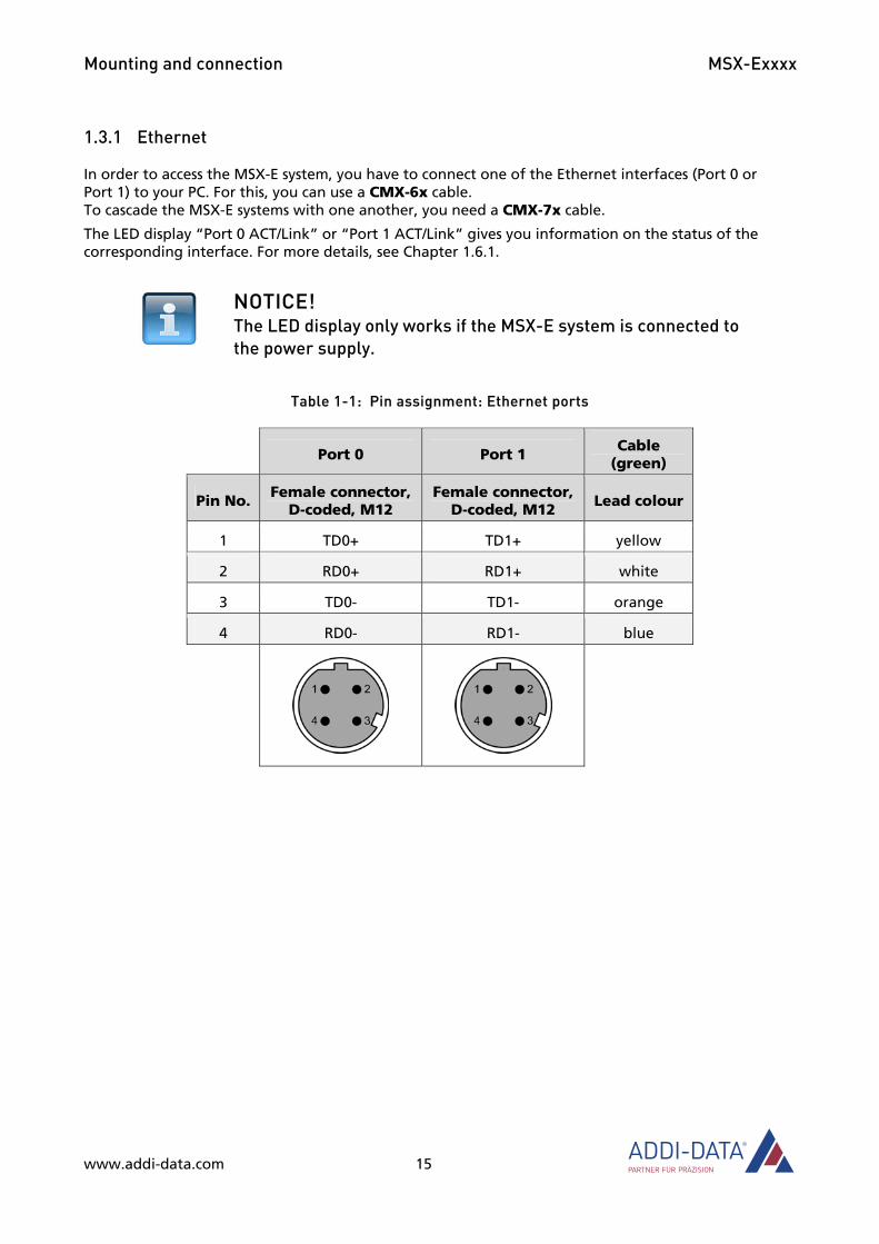
In order to access the MSX-E system, you have to connect one of the Ethernet interfaces (Port 0 or Port 1) to your PC. For this, you can use a CMX-6x cable. To cascade the MSX-E systems with one another, you need a CMX-7x cable.
The LED display “Port 0 ACT/Link” or “Port 1 ACT/Link” gives you information on the status of the corresponding interface. For more details, see Chapter 1.6.1.
NOTICE! The LED display only works if the MSX-E system is connected to the power supply.
Table 1-1: Pin assignment: Ethernet ports
Port 0 Port 1 Cable (green)
Pin No. Female connector, D-coded, M12
Female connector, D-coded, M12 Lead colour
1 TD0+ TD1+ yellow
2 RD0+ RD1+ white
3 TD0- TD1- orange
4 RD0- RD1- blue
www.addi-data.com 15

Mounting and connection MSX-Exxxx
1.3.2 Trigger/Synchro
Table 1-2: Pin assignment: Trigger/Synchro
Trig/Sync In Trig/Sync Out Cable (purple)
Pin No. Male connector, 5-pin, M12
Female connector, 5-pin, M12
Lead colour
Lead pair
1 Trigger input - Trigger input - blue
2 Trigger input + Trigger input + white 1
3 Synchro input + Synchro output + red
4 Synchro input - Synchro output - black 2
5 not connected not connected
Please use a shielded trigger/synchro cable.
Table 1-3: Trigger/Synchro cables
Name Cable end Length
CMX-40 Open end / female connector, 5-pin 1.5 m
CMX-41 Open end / female connector, 5-pin 3 m
CMX-42 Open end / female connector, 5-pin 5 m
CMX-43 Open end / female connector, 5-pin 10 m
CMX-49 Open end / female connector, 5-pin on request
CMX-50 Male connector, 5-pin / female connector, 5-pin 1.5 m
CMX-51 Male connector, 5-pin / female connector, 5-pin 3 m
CMX-52 Male connector, 5-pin / female connector, 5-pin 5 m
CMX-59 Male connector, 5-pin / female connector, 5-pin on request
CMX-59_0,3 Male connector, 5-pin / female connector, 5-pin 0.3 m
www.addi-data.com 16

Mounting and connection MSX-Exxxx
1.3.3 Power supply
Table 1-4: Pin assignment: Power supply (input and output)
24 VDC In 24 VDC Out Cable (black)
Pin No. Male connector, 5-pin, M12
Female connector, 5-pin, M12
Lead colour
1 24 V 24 V brown
2 24 V 24 V white
3 GND GND blue
4 GND GND black
5 not connected not connected grey
www.addi-data.com 17

Mounting and connection MSX-Exxxx
www.addi-data.com 18
1.4 Connecting the peripherals
Information on cables and other accessories can be found in the accessories list of the MSX-E systems.
1.4.1 Ethernet
Connect the Ethernet cable to the female connector “Port 0”.2
Fig. 1-10: Connect peripherals
2 If you want to connect several Ethernet systems, please read Chapter 1.5.
Trig/Sync In
24 VDC In (Power supply input)
24 VDC Out (Power supply output)
Port 0

Mounting and connection MSX-Exxxx
www.addi-data.com 19
1.4.2 Trigger/Synchro
Connect the trigger/synchro cable to the male connector “Trig/Sync In” (see Fig. 1-10).3
1.4.3 Power supply
Connect the power supply cable to the male connector “24 VDC In” (see Fig. 1-10).3
1.4.4 Sensors or actuators
Information concerning the type of sensor or actuator, the corresponding pin assignment as well as connection examples can be found in the respective system-specific MSX-E manual.
Fig. 1-11: Connect sensors or actuators (example)
3 If you want to connect several Ethernet systems, please read Chapter 1.5.
Mounting and connection MSX-Exxxx
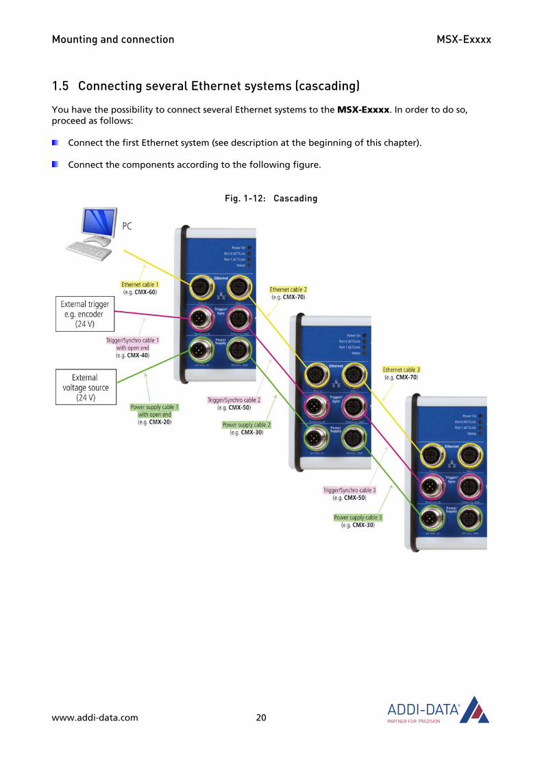
1.5 Connecting several Ethernet systems (cascading)
You have the possibility to connect several Ethernet systems to the MSX-Exxxx. In order to do so, proceed as follows:
Connect the first Ethernet system (see description at the beginning of this chapter).
Connect the components according to the following figure.
Fig. 1-12: Cascading
www.addi-data.com 20
Mounting and connection MSX-Exxxx
1.6 LED display
1.6.1 Overview
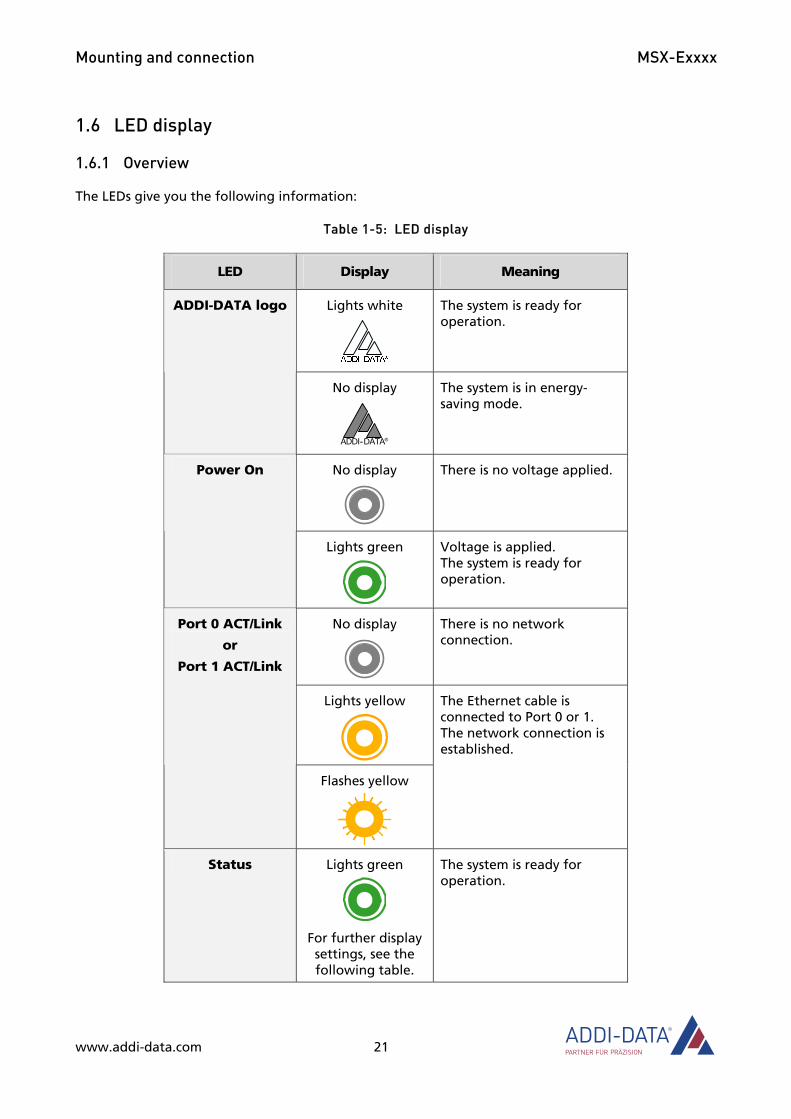
The LEDs give you the following information:
Table 1-5: LED display
LED Display Meaning
Lights white
The system is ready for operation.
ADDI-DATA logo
No display
ADDI-DATA®
The system is in energy-saving mode.
No display
There is no voltage applied. Power On
Lights green
Voltage is applied. The system is ready for operation.
No display
There is no network connection.
Lights yellow
Port 0 ACT/Link
or
Port 1 ACT/Link
Flashes yellow
The Ethernet cable is connected to Port 0 or 1. The network connection is established.
Status Lights green
For further display settings, see the following table.
The system is ready for operation.
www.addi-data.com 21
Mounting and connection MSX-Exxxx
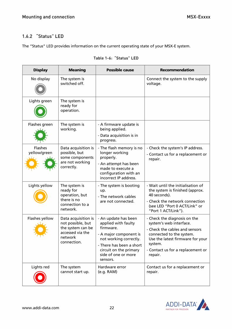
1.6.2 “Status” LED
The “Status” LED provides information on the current operating state of your MSX-E system.
Table 1-6: “Status” LED
Display Meaning Possible cause Recommendation
No display
The system is switched off.
Connect the system to the supply voltage.
Lights green
The system is ready for operation.
Flashes green
The system is working.
- A firmware update is being applied.
- Data acquisition is in progress.
Flashes yellow/green
Data acquisition is possible, but some components are not working correctly.
- The flash memory is no longer working properly.
- An attempt has been made to execute a configuration with an incorrect IP address.
- Check the system’s IP address.
- Contact us for a replacement or repair.
Lights yellow
The system is ready for operation, but there is no connection to a network.
- The system is booting up.
- The network cables are not connected.
- Wait until the initialisation of the system is finished (approx. 40 seconds).
- Check the network connection (see LED “Port 0 ACT/Link” or “Port 1 ACT/Link”).
Flashes yellow
Data acquisition is not possible, but the system can be accessed via the network connection.
- An update has been applied with faulty firmware.
- A major component is not working correctly.
- There has been a short circuit on the primary side of one or more sensors.
- Check the diagnosis on the system’s web interface.
- Check the cables and sensors connected to the system. Use the latest firmware for your system.
- Contact us for a replacement or repair.
Lights red
The system cannot start up.
Hardware error (e.g. RAM)
Contact us for a replacement or repair.
www.addi-data.com 22
Mounting and connection MSX-Exxxx
www.addi-data.com 23
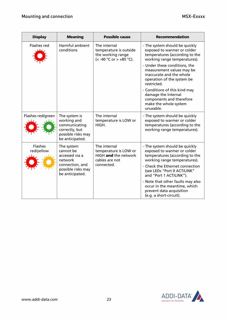
Display Meaning Possible cause Recommendation
Flashes red
Harmful ambient conditions
The internal temperature is outside the working range (< -40 °C or > +85 °C).
- The system should be quickly exposed to warmer or colder temperatures (according to the working range temperatures).
- Under these conditions, the measurement values may be inaccurate and the whole operation of the system be restricted.
- Conditions of this kind may damage the internal components and therefore make the whole system unusable.
Flashes red/green
The system is working and communicating correctly, but possible risks may be anticipated.
The internal temperature is LOW or HIGH.
- The system should be quickly exposed to warmer or colder temperatures (according to the working range temperatures).
Flashes red/yellow
The system cannot be accessed via a network connection, and possible risks may be anticipated.
The internal temperature is LOW or HIGH and the network cables are not connected.
- The system should be quickly exposed to warmer or colder temperatures (according to the working range temperatures).
- Check the Ethernet connection (see LEDs “Port 0 ACT/LINK” and “Port 1 ACT/LINK”).
- Note that other faults may also occur in the meantime, which prevent data acquisition (e.g. a short-circuit).

Software tool “ConfigTools” MSX-Exxxx
2 Software tool “ConfigTools” The software tool ConfigTools supports you in working with your Ethernet system. It allows you, for example, to change the IP address, carry out firmware updates and calibrate connected transducers.
2.1 First steps
ConfigTools is to be found on the supplied CD. To install this software tool, proceed as follows:
Insert the CD “MSX-E Systems” into your CD drive.
The CD browser interface is automatically displayed. If not, open the Windows Explorer, and in the CD root directory, double-click on the file “AD-Systems.exe”.
Select the desired language and click on “Start”.
Click on the desired MSX-E system, and after that, under “Configuration”, on the “ConfigTools” button.
Follow the instructions of the installation program.
As soon as you have started the installed software tool from your computer, the connected MSX-E systems are scanned.
Fig. 2-1: ConfigTools: Scan MSX-E systems
www.addi-data.com 24
Software tool “ConfigTools” MSX-Exxxx
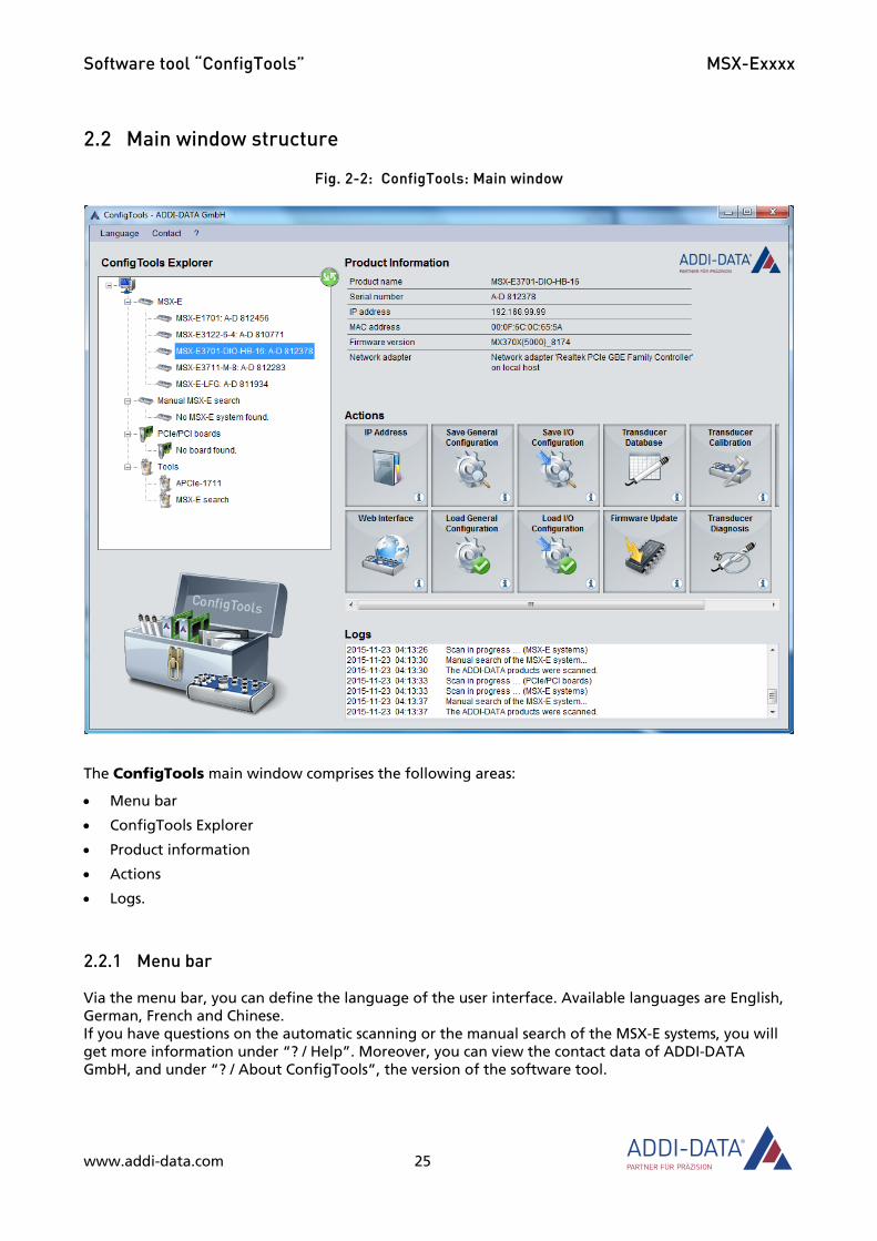
2.2 Main window structure
Fig. 2-2: ConfigTools: Main window
The ConfigTools main window comprises the following areas:
• Menu bar
• ConfigTools Explorer
• Product information
• Actions
• Logs.
2.2.1 Menu bar
Via the menu bar, you can define the language of the user interface. Available languages are English, German, French and Chinese. If you have questions on the automatic scanning or the manual search of the MSX-E systems, you will get more information under “? / Help”. Moreover, you can view the contact data of ADDI-DATA GmbH, and under “? / About ConfigTools”, the version of the software tool.
www.addi-data.com 25

Software tool “ConfigTools” MSX-Exxxx
2.2.2 ConfigTools Explorer
After scanning, all connected MSX-E systems are displayed in the ConfigTools Explorer. When you click on the name of one of these systems, corresponding product information such as IP address, MAC address and firmware version will be shown on the right side of the main window.
To scan the connected systems once again, for example after connecting another MSX-E system, you have to click on the green icon in the top right of the ConfigTools Explorer area.
Fig. 2-3: ConfigTools: MSX-E search
Under the entry “Tools”, if you click on “MSX-E search”, the buttons “Manual Search” and “Network Interfaces” will be displayed on the right side of the main window. MSX-E systems that have been found through the manual search are indicated in the ConfigTools-Explorer under “Manual MSX-E search”. Via the “Network Interfaces” button, all of the network interfaces detected by ConfigTools are listed.
More detailed information on the automatic scanning or the manual search of the MSX-E systems is to be found in the ConfigTools Help (see Chapter 2.2.1).
www.addi-data.com 26

Software tool “ConfigTools” MSX-Exxxx
www.addi-data.com 27
2.2.3 Actions
Below the “Product Information” area, there are buttons that enable you to perform various actions and to access the web interface of your MSX-E system.
Fig. 2-4: ConfigTools: Action buttons
The following actions are possible:
• IP Address: Change the IP address of the MSX-E system in order to adapt it to your corporate network, for example (see also Chapter 4.4.1).
• Web Interface: Access the web interface of your MSX-E system and change the configuration (see also Chapter 4).
• Save General Configuration: Save the general configuration of the MSX-E system (including, for example, the network configuration), i.e. all the settings defined on the web interface apart from the I/O configuration.
• Load General Configuration: Load a file containing the general configuration of the MSX-E system.
• Save I/O Configuration: Save all function-specific settings defined on the web interface under “I/O Configuration” (see also Chapter 4.5).
• Load I/O Configuration: Load a function-specific configuration (see also Chapter 4.5).
• Transducer Database: Edit the user’s transducer database, that is, for example, change transducer features and add new transducers. The MSX-E database must contain the transducers that will be connected to the MSX-E system in order for the system to detect them.
• Firmware Update: Update the firmware of the MSX-E system. The required firmware file is available on request. The file name corresponds to the firmware version.
• Transducer Calibration: Calibrate transducers connected to one or more channels.
• Transducer Diagnosis: Test transducers for errors (short-circuit, open load)
• Transducer Monitoring: Select the channels to be acquired and start the acquisition with monitoring. For each channel, each acquired value is immediately displayed in a diagram.
NOTICE! Depending on the MSX-E system, a different number of buttons and accordingly, different types of actions are available.
Function description: General functions MSX-Exxxx
3 Function description: General functions In this chapter, you will learn more about general functions that are available with all Ethernet systems:
• Hardware trigger
• Synchronisation
• Time stamp (time and date)
• Temperature monitoring
• Customer key.
Information on other general functions (e.g. for the application of the samples stored in the “MSX-Exxxx” folder on the MSX-E CD) is to be found in Chapters 4 and 5:
• General system configuration: e.g. saving and loading the configuration (Chapters 4.3.3, 4.4 and 4.8)
• I/O configuration: e.g. autostart (Chapter 4.5)
• Data server: e.g. TCP/IP and ACK modes (Chapters 4.8 and 5)
• Event server: system state and subsystems (Chapters 4.3.2 and 5)
• Password (Chapter 4.3.3) and hostname (Chapter 4.4.2)
• Reboot (Chapter 4.3.4)
• Sample “ResetAllIOFunctions”: Depending on the MSX-E-System, acquisition, calibration, watchdog, etc. are stopped (see SOAP function).
• Sample “TestErrorString”: testing the error return.
3.1 Hardware trigger
The digital 24 V trigger input of the MSX-E system can be used to start an acquisition. You can select if the rising edge, the falling edge or both edges of the trigger signal generated externally should count. By means of the counter, you can define the number of edges after which the acquisition is to be started.
Examples:
• Selected edge: rising Counter value: 1 The acquisition is started after every rising edge of the trigger signal.
• Selected edge: rising Counter value: 3 The acquisition is started after every third rising edge of the trigger signal.
• Selected edge: rising and falling Counter value: 3 The acquisition is started after every third edge of the trigger signal.
In order to suppress interfering signals, a software-programmable digital filter can be used for the trigger input.
www.addi-data.com 28

Function description: General functions MSX-Exxxx
The filter time may be in the range between 250 ns and 16.38 ms. When the filter is activated, every positive or negative pulse lasting shorter than the defined filter time is suppressed.
Example
The acquisition should be triggered after a rising edge.
The trigger signal always lasts longer than 10 ms. However, as it is not clean and bounces, this creates short voltage peaks of ~4 ms. In order that these bouncing signals are no longer identified as triggers, a filter of 10 ms is configured.
Trigger signal duration > 10 ms: Trigger identified as a trigger
Trigger signal duration < 10 ms: Trigger is ignored
Fig. 3-1: Example of a trigger
Acquisition
Trigger
15 ms
15 ms ~4 ms ~4ms
3.2 Synchronisation
The trigger/synchro output and input of the Ethernet system MSX-Exxxx can be used to synchronise multiple MSX-E systems with one another (see Fig. 1-12). This makes it possible to start the data acquisition on multiple MSX-E systems simultaneously, to generate trigger events and to synchronise the time. Depending on the MSX-E system, the trigger/synchro signal can be generated by the timer function or also by the compare logic.
3.2.1 Master and slaves
An MSX-E system is detected as a master if it does not receive a signal from another MSX-E system at the trigger/synchro input (“Trig/Sync In”). Consequently, MSX-E systems are detected as slaves if they receive such a signal.
NOTICE! Only a master can generate a trigger/synchro signal and synchronise the time of the slaves.
www.addi-data.com 29

Function description: General functions MSX-Exxxx
3.3 Time stamp
According to the functions and settings, a time stamp is available. You can use it to record the time at which the system acquired the data. Details on the time stamp format can be found in Chapter 5.5.2.
3.3.1 Time and date
Once an MSX-E system is no longer supplied with voltage, the UTC time, which depends on the time zone, as well as the date are reset to the 1 January 1970. An NTP/SOAP command allows you to refresh the time and the date though (see MSX-E web interface, menu item “NTP client”).
3.4 Temperature monitoring
With temperature monitoring, you can read the temperature of the Ethernet system and set a temperature warning limit.
Table 3-1: Temperature monitoring: MSX-Exxxx
Temperature Meaning
-30 °C to +70 °C Temperature warning limit range
< -40 °C or > +85 °C The Ethernet system shuts down automatically.
For the Ethernet systems MSX-E3700 and MSX-E3701, other values apply:
Table 3-2: Temperature monitoring: MSX-E3700 and MSX-E3701
Temperature Meaning
+5 °C to +60 °C Temperature warning limit range
< 0 °C or > +70 °C The Ethernet system shuts down automatically.
A list of all available software functions, with explanations, can be found in the SOAP documentation of the respective Ethernet system (see MSX-E CD or driver download on the ADDI-DATA website).
3.5 Customer key (security feature)
If you want to protect a package made up of a software application and one or more MSX-E systems and ensure that the application can only be run with the specified hardware, the Customer Key is a practical solution. This provides for certification between the MSX-E system and the application.
www.addi-data.com 30

Function description: General functions MSX-Exxxx
www.addi-data.com 31
Table 3-3: Customer key
Customer key available
Software MSX-E system
Application possible
yes yes
yes (only with identical
customer keys)
yes no no
no yes yes
no no yes
To certify the MSX-E system, the user can define two keys in the MSX-E system, which are saved with the software function “MXCommon__SetCustomerKey”:
• a public key K1 (16 bytes)
• a private key K2 (32 bytes).
The software function “MXCommon__TestCustomerID” is then used to check whether the MSX-E system is certified. When this software function is executed, a random 16-bit value is generated in the MSX-E system, which is encrypted using the two stored keys K1 and K2 and the AES algorithm (Rijndael). The software function “MXCommon__TestCustomerID” then returns two arrays of 16 bytes each:
• one array with the random value [A]
• one array with the encrypted value [B] ([B] = result of calculating “AES ([A], K1, K2)”).
In the software application, the calculation AES ([A], K1, K2) has to be performed with the random value [A] from the MSX-E system. The result [B] from the software application is then compared with the result [B] from the MSX-E system, and the two results must match (see SOAP example on the CD “MSX-E Systems” in the folder “MSX-E Common/ CustomerKey”). An identical result means that the MSX-E system has been configured with the correct certificate (keys K1 and K2) and is therefore suitable for the software application.
It is the responsibility of the application developer to ensure that these Customer Keys are protected within his software application against unauthorised access.
It is always possible to generate a new Customer Key in the MSX-E system. In the event of a change, the software also needs to be modified to ensure that it still works. For security reasons, a change to the Customer Key in the MSX-E system may be prohibited. The blocking option can be activated on the web interface of the MSX-E system (menu item “System/Security”, section “Remote general system configuration authorisation”).
The use of the Customer Key has no effect on other functions of the Ethernet system.
Web interface: Quick access to the MSX-E system MSX-Exxxx
4 Web interface: Quick access to the MSX-E system From the web interface of your MSX-E system, you can access the system quickly and manage your functions conveniently without programming.
NOTICE! The web interface of the MSX-E systems has been modified by now in terms of design and structure. Differences to the previous version are indicated in the relevant chapters.
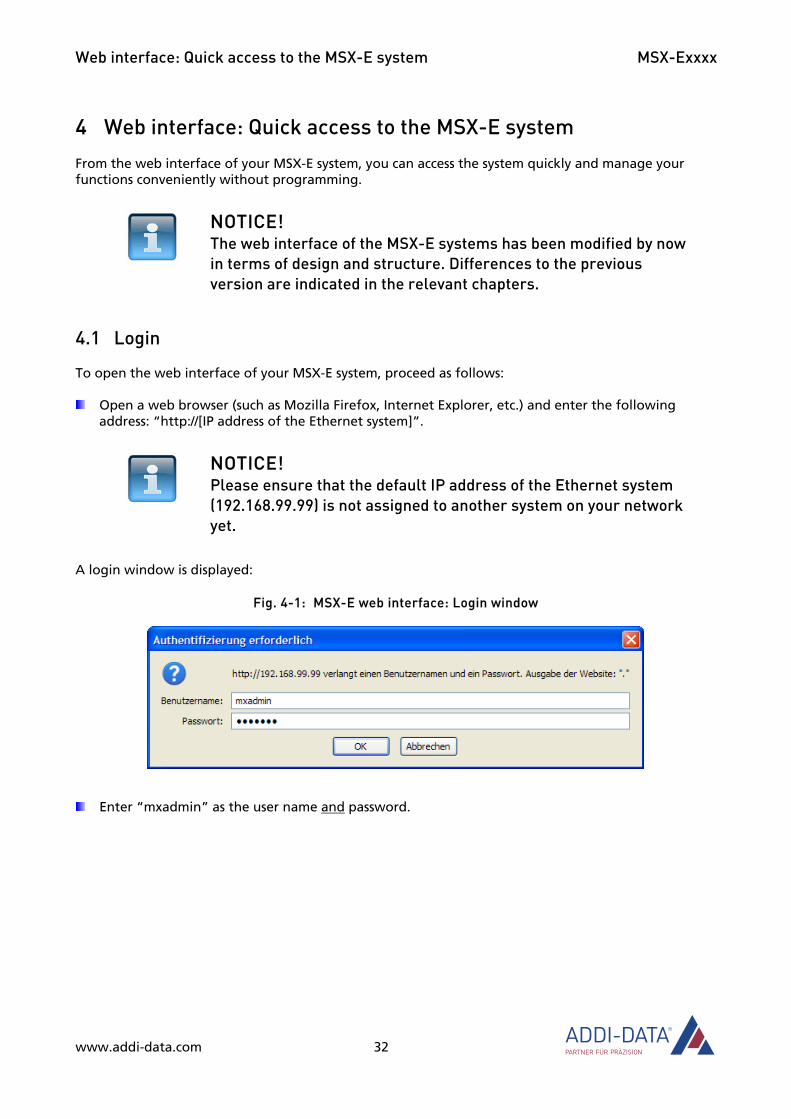
4.1 Login
To open the web interface of your MSX-E system, proceed as follows:
Open a web browser (such as Mozilla Firefox, Internet Explorer, etc.) and enter the following address: “http://[IP address of the Ethernet system]”.
NOTICE! Please ensure that the default IP address of the Ethernet system (192.168.99.99) is not assigned to another system on your network yet.
A login window is displayed:
Fig. 4-1: MSX-E web interface: Login window
Enter “mxadmin” as the user name and password.
www.addi-data.com 32
Web interface: Quick access to the MSX-E system MSX-Exxxx
4.2 Navigation
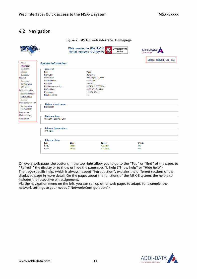
Fig. 4-2: MSX-E web interface: Homepage
On every web page, the buttons in the top right allow you to go to the “Top” or “End” of the page, to “Refresh” the display or to show or hide the page-specific help (“Show help” or “Hide help”). The page-specific help, which is always headed “Introduction”, explains the different sections of the displayed page in more detail. On the pages about the functions of the MSX-E system, the help also includes the respective pin assignment. Via the navigation menu on the left, you can call up other web pages to adapt, for example, the network settings to your needs (“Network/Configuration”).
www.addi-data.com 33

Web interface: Quick access to the MSX-E system MSX-Exxxx
Fig. 4-3: MSX-E web interface: Homepage (new)
4.3 “System”
4.3.1 Menu item or tab “Information”
After you have successfully logged in, the web interface of the MSX-E system shows an overview (see Fig. 4-2 or Fig. 4-3). Here, you get general information on the MSX-E system such as serial number, the firmware used, host name and system time.
www.addi-data.com 34

Web interface: Quick access to the MSX-E system MSX-Exxxx
4.3.2 Menu item or tab “Diagnosis”
This page or tab (see Fig. 4-4 or Fig. 4-5) gives you information on the current state of the MSX-E system.
Fig. 4-4: MSX-E web interface: System/Diagnosis
www.addi-data.com 35
Web interface: Quick access to the MSX-E system MSX-Exxxx
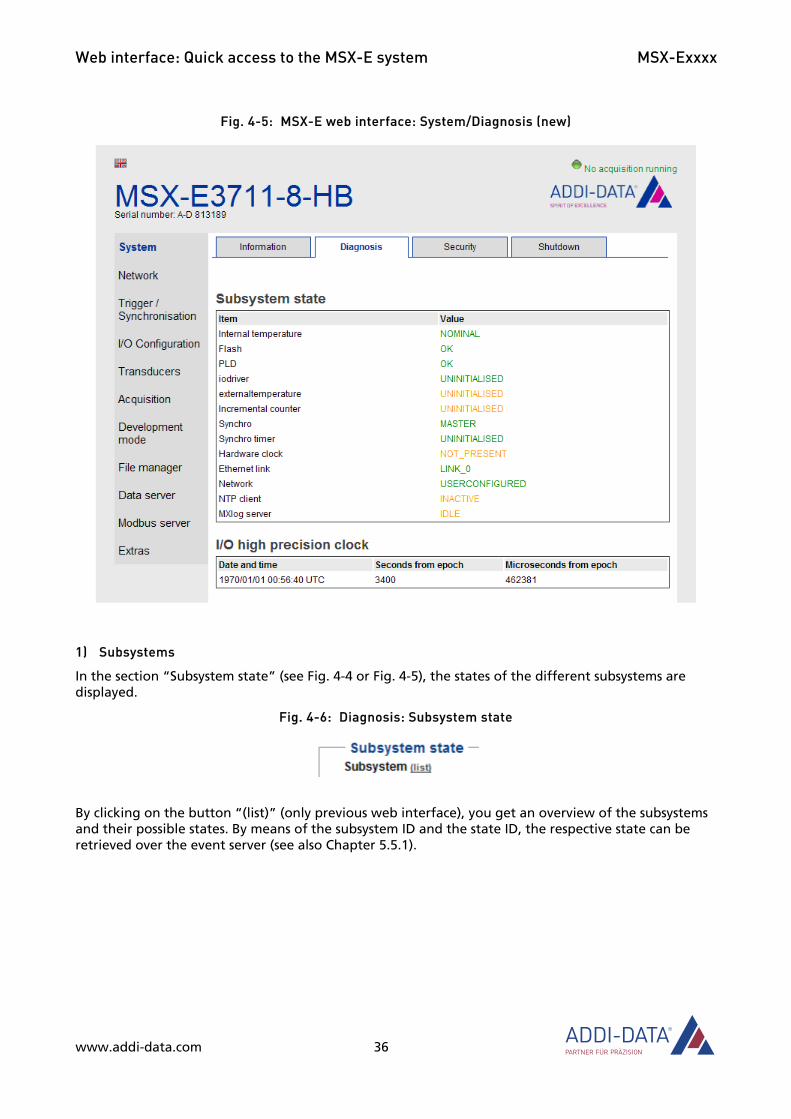
Fig. 4-5: MSX-E web interface: System/Diagnosis (new)
1) Subsystems
In the section “Subsystem state” (see Fig. 4-4 or Fig. 4-5), the states of the different subsystems are displayed.
Fig. 4-6: Diagnosis: Subsystem state
By clicking on the button “(list)” (only previous web interface), you get an overview of the subsystems and their possible states. By means of the subsystem ID and the state ID, the respective state can be retrieved over the event server (see also Chapter 5.5.1).
www.addi-data.com 36

Web interface: Quick access to the MSX-E system MSX-Exxxx
Fig. 4-7: Subsystems & states
2) Date and time
The current date and time of the MSX-E system are indicated in the section “I/O high precision clock”.
Fig. 4-8 Diagnosis: I/O high precision clock
Fig. 4-9: Diagnosis: I/O high precision clock (new)
3) Memory state
In the section “Resources”, the current memory space of the RAM memory and that of the permanent memory are displayed.
www.addi-data.com 37

Web interface: Quick access to the MSX-E system MSX-Exxxx
Fig. 4-10: Diagnosis: Resources
Fig. 4-11: Diagnosis: Resources (new)
4) Synchronisation commands
The section “Inter-system synchronisation” contains information on synchronisation commands.
Fig. 4-12: Diagnosis: Inter-system synchronisation
www.addi-data.com 38
Web interface: Quick access to the MSX-E system MSX-Exxxx
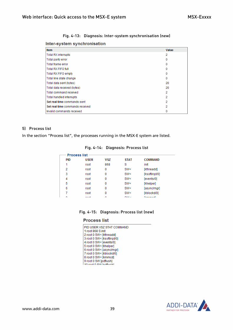
Fig. 4-13: Diagnosis: Inter-system synchronisation (new)
5) Process list
In the section “Process list”, the processes running in the MSX-E system are listed.
Fig. 4-14: Diagnosis: Process list
Fig. 4-15: Diagnosis: Process list (new)
www.addi-data.com 39
Web interface: Quick access to the MSX-E system MSX-Exxxx
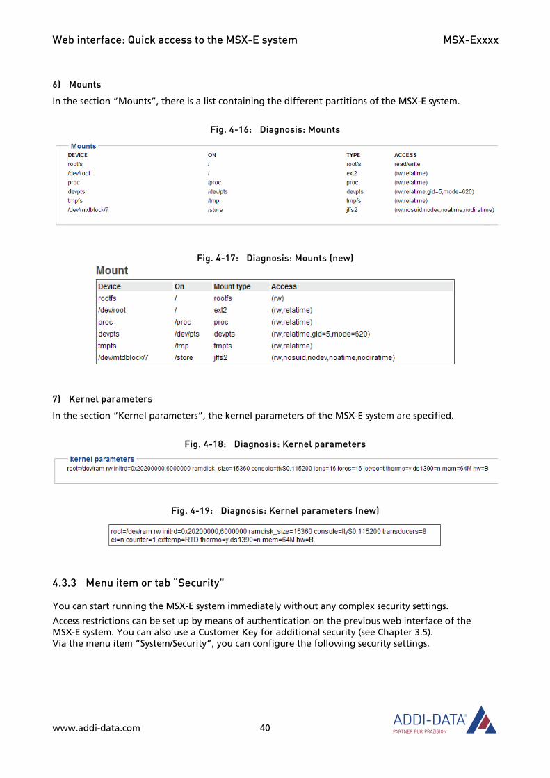
6) Mounts
In the section “Mounts”, there is a list containing the different partitions of the MSX-E system.
Fig. 4-16: Diagnosis: Mounts
Fig. 4-17: Diagnosis: Mounts (new)
7) Kernel parameters
In the section “Kernel parameters”, the kernel parameters of the MSX-E system are specified.
Fig. 4-18: Diagnosis: Kernel parameters
Fig. 4-19: Diagnosis: Kernel parameters (new)
4.3.3 Menu item or tab “Security”
You can start running the MSX-E system immediately without any complex security settings.
Access restrictions can be set up by means of authentication on the previous web interface of the MSX-E system. You can also use a Customer Key for additional security (see Chapter 3.5). Via the menu item “System/Security”, you can configure the following security settings.
www.addi-data.com 40

Web interface: Quick access to the MSX-E system MSX-Exxxx
1) Access configuration
By default, the user name and password are both “mxadmin”.
Fig. 4-20: “Security”: Enter new password
Fig. 4-21: “Security”: Enter new password (new)
To change the password, enter the new password in the section “Webserver user name/password”, in the “Configuration” area (new web interface: “Configuration” section), in the field “New password” and again in the field “Confirm new password”.
For this, please note the following:
• You should choose a password that is hard to guess.
• Keep the password out of sight of other people!
• All of the fields for the user name (“Identification” and “Confirm identification”) and password (“New password” and “Confirm password”) must be filled in.
• Any changes take immediately effect.
After entering the new password, click on the “Save new authentication” or “Set and save” button.
To prevent problems, the database that also contains the password is duplicated. If your new password is not detected, you have to enter the old password again.
NOTICE! Please note that this online form is the only way of changing the password from a remote computer or over the network.
www.addi-data.com 41

Web interface: Quick access to the MSX-E system MSX-Exxxx
2) TLS encryption for the web server (only previous web interface)
With standard data transfer methods, unwanted eavesdropping is possible. There is then a risk that unauthorised persons could obtain the password to log in to the web interface and thus operate the MSX-E system. That is why we advise you to activate TLS encryption. The TLS protocol is the successor to the SSL protocol for secure communication over the Internet. The web server can use this protocol to encrypt communication with the client.
TLS encryption is not set as the default within the MSX-E systems, as not all web client applications use the TLS protocol and specific configuration settings may be needed. Also, not all web service development tools support an encrypted connection when downloading a WSDL file.
The web server can be modified to use the TLS protocol. The protocol identification is then set to HTTPS (example: https://192.168.99.99). This assumes that the TLS protocol is enabled within the client browser. The configuration varies between browsers.
NOTICE! If the web server uses TLS, the connection must be set up to the HTTPS port (443) and not to the HTTP port (80).
Fig. 4-22: “Security”: TLS encryption
In the section “TLS encryption for the web server”, click on the button “The web server should use TLS” to use TLS the next time the system is restarted.
3) Authorisation settings (only previous web interface)
Changes to the system configuration from remote computers can be restricted or prohibited. If one of the following options is blocked, this change takes immediately effect. It can be reset via the button of the corresponding option.
www.addi-data.com 42

Web interface: Quick access to the MSX-E system MSX-Exxxx
a) Remote call “SetTime()”
The SOAP function “soap_call_MXCommon_SetTime()” enables the MSX-E system clock to be changed. By default, it is allowed to call this function from remote computers.
Fig. 4-23: “Security”: Remote call “SetTime()”
In the section “Remote SetTime() call authorisation”, click on “Do not allow remote SetTime() call” to block remote calling of this function.
This setting has no effect on the SNTP client.
Tip: Time synchronisation by the NTP server is still supported even though remote “SetTime” calls are blocked. This option is especially suited to production systems.
b) Remote calls “autoconf/autostart”
The default setting allows the SOAP functions “SetAutoConfigurationFile()” and “StartAutoConfiguration()” for the autostart of the I/O configuration to be called from remote computers.
Fig. 4-24: “Security”: Remote calls “autoconf/autostart”
In the section “Remote autoconf/autostart authorisation”, click on “Do not allow remote autoconf/autostart changes” to block remote calling of these functions.
This setting has no effect on the web interface.
Tip: We advise you to set this option in a production system.
www.addi-data.com 43
Web interface: Quick access to the MSX-E system MSX-Exxxx
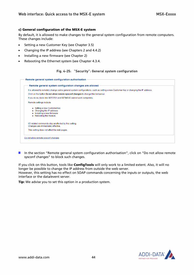
c) General configuration of the MSX-E system
By default, it is allowed to make changes to the general system configuration from remote computers. These changes include:
• Setting a new Customer Key (see Chapter 3.5)
• Changing the IP address (see Chapters 2 and 4.4.2)
• Installing a new firmware (see Chapter 2)
• Rebooting the Ethernet system (see Chapter 4.3.4.
Fig. 4-25: ”Security”: General system configuration
In the section “Remote general system configuration authorisation”, click on “Do not allow remote sysconf changes” to block such changes.
If you click on this button, tools like ConfigTools will only work to a limited extent. Also, it will no longer be possible to change the IP address from outside the web server. However, this setting has no effect on SOAP commands concerning the inputs or outputs, the web interface or the data/event server.
Tip: We advise you to set this option in a production system.
www.addi-data.com 44
Web interface: Quick access to the MSX-E system MSX-Exxxx
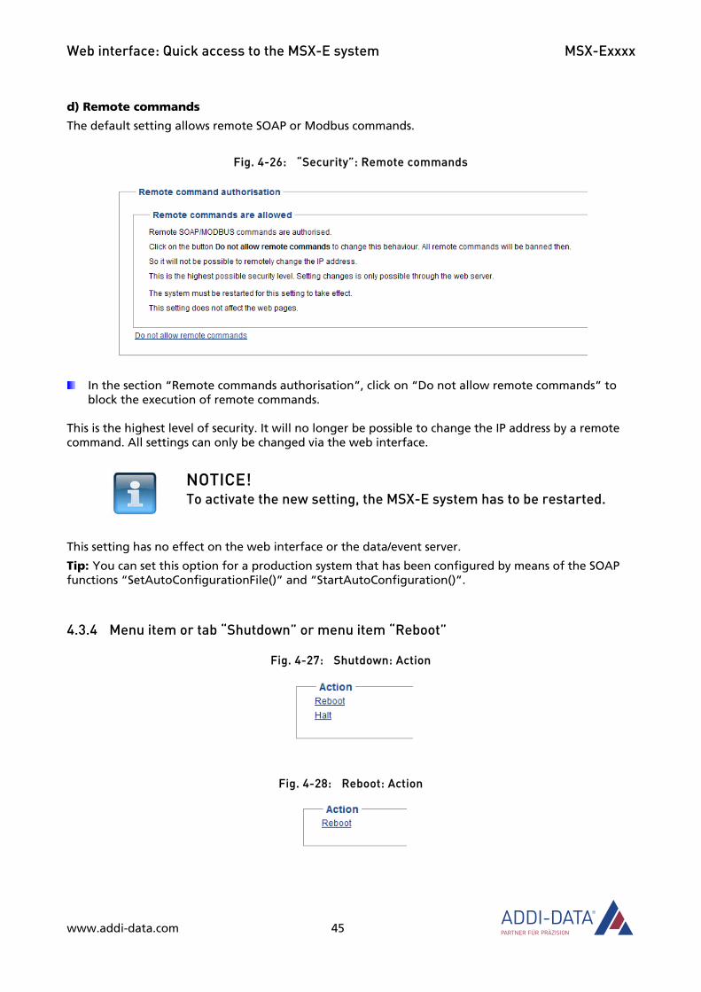
d) Remote commands
The default setting allows remote SOAP or Modbus commands.
Fig. 4-26: “Security”: Remote commands
In the section “Remote commands authorisation”, click on “Do not allow remote commands” to block the execution of remote commands.
This is the highest level of security. It will no longer be possible to change the IP address by a remote command. All settings can only be changed via the web interface.
NOTICE! To activate the new setting, the MSX-E system has to be restarted.
This setting has no effect on the web interface or the data/event server.
Tip: You can set this option for a production system that has been configured by means of the SOAP functions “SetAutoConfigurationFile()” and “StartAutoConfiguration()”.
4.3.4 Menu item or tab “Shutdown” or menu item “Reboot”
Fig. 4-27: Shutdown: Action
Fig. 4-28: Reboot: Action
www.addi-data.com 45

Web interface: Quick access to the MSX-E system MSX-Exxxx
Fig. 4-29: Shutdown: Action (new)
When you click on “Reboot”, the MSX-E system is rebooted. By clicking on the “Halt” button (only previous web interface), the operating system of the MSX-E system is stopped so that the MSX-E system can be switched off safely.
4.4 “Network”
4.4.1 Menu item or tab “Diagnosis”
On this web page or tab, the states of the TCP and UDP connections are displayed.
Fig. 4-30: “Diagnosis”: TCP and UDP
www.addi-data.com 46
Web interface: Quick access to the MSX-E system MSX-Exxxx
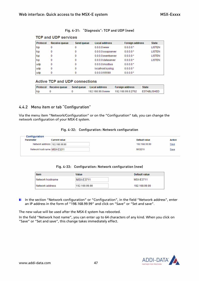
Fig. 4-31: “Diagnosis”: TCP and UDP (new)
4.4.2 Menu item or tab “Configuration”
Via the menu item “Network/Configuration” or on the “Configuration” tab, you can change the network configuration of your MSX-E system.
Fig. 4-32: Configuration: Network configuration
Fig. 4-33: Configuration: Network configuration (new)
In the section “Network configuration” or “Configuration”, in the field “Network address”, enter an IP address in the form of “198.168.99.99” and click on “Save” or “Set and save”.
The new value will be used after the MSX-E system has rebooted.
In the field “Network host name”, you can enter up to 64 characters of any kind. When you click on “Save” or “Set and save”, this change takes immediately effect.
www.addi-data.com 47

Web interface: Quick access to the MSX-E system MSX-Exxxx
The MSX-E system can send logging information to a system in the network by using the syslog protocol.
Fig. 4-34: Configuration: Syslog (network logging)
Fig. 4-35: Configuration: Syslog (network logging) (new)
In the section “Syslog (network logging)” or “Syslog”, in the field “Syslog Target”, enter the IP address of the system that receives the information and click on “Save” or “Set and save”.
If the “Syslog Target” field is left blank, this function is deactivated.
The “Syslog Port” field contains the port number (UDP) that should be used. It must be a number between 1 and 65535. 514 is defined as the default value.
The new configuration will take effect when the MSX-E system is restarted.
4.4.3 “Advanced” network mode or tab
In the “Advanced” network mode (menu item “Network/Configuration”, “Click to allow advanced network mode” button) or on the “Advanced” tab (new web interface), advanced network settings can be made.
NOTICE! Changes that are not appropriate to your network may cause problems in communication with the MSX-E system.
www.addi-data.com 48

Web interface: Quick access to the MSX-E system MSX-Exxxx
Fig. 4-36: Advanced network configuration
Fig. 4-37: Advanced network configuration (new)
The following parameters can be set:
• Netmask: IP network mask for this interface; default value of the usual class A, B or C network mask (as derived from the interface IP address) or any value
• Gateway: is added to the routing table; valid or symbolic IP address, or 0.0.0.0 if not available
• Broadcast address: Broadcast address of the protocol for this interface; in case of the value 0.0.0.0, it is automatically computed from IP address and network mask; optional field
Fig. 4-38: DHCP
www.addi-data.com 49

Web interface: Quick access to the MSX-E system MSX-Exxxx
Fig. 4-39: DHCP (new)
If a DHCP server is available on your network, you can use it in order to get an IP address for your MSX-E system. For this purpose, the relevant parameters must be set.
Fig. 4-40: /etc/hosts, Sysctl and Eth0 (new)
www.addi-data.com 50

Web interface: Quick access to the MSX-E system MSX-Exxxx
On the new web interface, in the “/etc/hosts” section, you can connect hostnames with IP addresses. The maximum size of the socket receive buffer can be defined in the “Sysctl” section. In the “Eth0 initialisation log” section, the logs of the eth0 interface are displayed.
4.4.4 Menu item or tab “NTP client”
In order to synchronise the time of the MSX-E system with that of the NTP server, the NTP client has to be configured.
Fig. 4-41: NTP client: Configuration
Fig. 4-42: NTP client: Configuration (new)
The following parameters need to be defined:
• NTP-Server 1: IP address of NTP server 1 (if not activated, enter 0.0.0.0)
• NTP-Server 2: IP address of NTP server 2 (if not activated, enter 0.0.0.0)
• Number of seconds to wait before retrying
• Verbosity: Detail level of debug messages
4.5 “I/O Configuration” or “Trigger/Synchronisation” (new)
The following menu items under “I/O Configuration” or the following tabs under “Trigger/Synchronisation” are available on each MSX-E web interface (exception: menu item “Synchro timer” only available with master systems). The other menu items or tabs under “I/O Configuration” solely relate to the respective MSX-E system and are explained in more detail in the corresponding system-specific MSX-E manual. This also applies to the menu items “Transducers” and “Acquisition” on the new web interface.
www.addi-data.com 51
Web interface: Quick access to the MSX-E system MSX-Exxxx
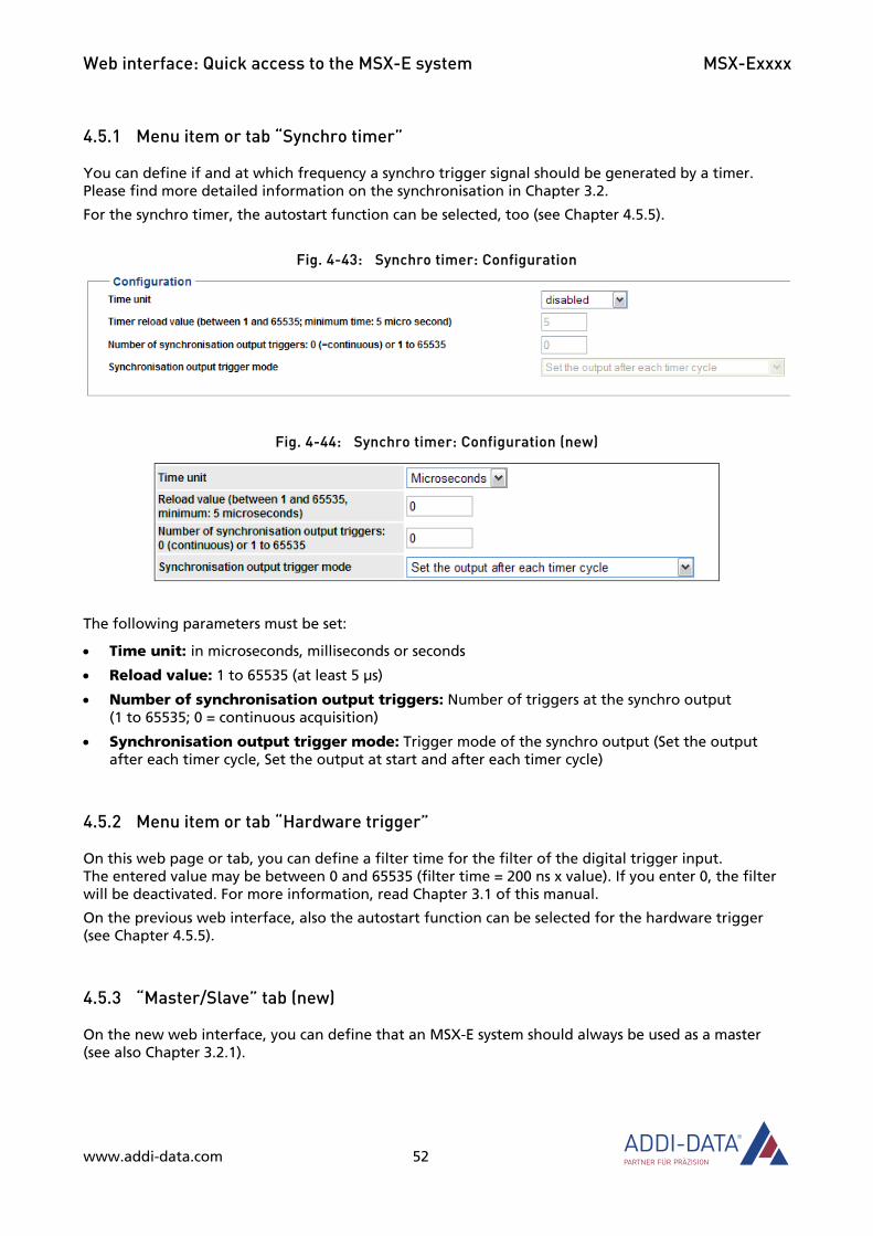
4.5.1 Menu item or tab “Synchro timer”
You can define if and at which frequency a synchro trigger signal should be generated by a timer. Please find more detailed information on the synchronisation in Chapter 3.2.
For the synchro timer, the autostart function can be selected, too (see Chapter 4.5.5).
Fig. 4-43: Synchro timer: Configuration
Fig. 4-44: Synchro timer: Configuration (new)
The following parameters must be set:
• Time unit: in microseconds, milliseconds or seconds
• Reload value: 1 to 65535 (at least 5 μs)
• Number of synchronisation output triggers: Number of triggers at the synchro output (1 to 65535; 0 = continuous acquisition)
• Synchronisation output trigger mode: Trigger mode of the synchro output (Set the output after each timer cycle, Set the output at start and after each timer cycle)
4.5.2 Menu item or tab “Hardware trigger”
On this web page or tab, you can define a filter time for the filter of the digital trigger input. The entered value may be between 0 and 65535 (filter time = 200 ns x value). If you enter 0, the filter will be deactivated. For more information, read Chapter 3.1 of this manual.
On the previous web interface, also the autostart function can be selected for the hardware trigger (see Chapter 4.5.5).
4.5.3 “Master/Slave” tab (new)
On the new web interface, you can define that an MSX-E system should always be used as a master (see also Chapter 3.2.1).
www.addi-data.com 52
Web interface: Quick access to the MSX-E system MSX-Exxxx
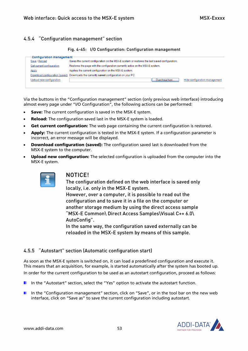
4.5.4 “Configuration management” section
Fig. 4-45: I/O Configuration: Configuration management
Via the buttons in the “Configuration management” section (only previous web interface) introducing almost every page under “I/O Configuration”, the following actions can be performed:
• Save: The current configuration is saved in the MSX-E system.
• Reload: The configuration saved last in the MSX-E system is loaded.
• Get current configuration: The web page containing the current configuration is restored.
• Apply: The current configuration is tested in the MSX-E system. If a configuration parameter is incorrect, an error message will be displayed.
• Download configuration (saved): The configuration saved last is downloaded from the MSX-E system to the computer.
• Upload new configuration: The selected configuration is uploaded from the computer into the MSX-E system.
NOTICE! The configuration defined on the web interface is saved only locally, i.e. only in the MSX-E system. However, over a computer, it is possible to read out the configuration and to save it in a file on the computer or another storage medium by using the direct access sample “MSX-E Common\ Direct Access Samples\Visual C++ 6.0\ AutoConfig”. In the same way, the configuration saved externally can be reloaded in the MSX-E system by means of this sample.
4.5.5 “Autostart” section (Automatic configuration start)
As soon as the MSX-E system is switched on, it can load a predefined configuration and execute it. This means that an acquisition, for example, is started automatically after the system has booted up.
In order for the current configuration to be used as an autostart configuration, proceed as follows:
In the “Autostart” section, select the “Yes” option to activate the autostart function.
In the “Configuration management” section, click on “Save”, or in the tool bar on the new web interface, click on “Save as” to save the current configuration including autostart.
www.addi-data.com 53

Web interface: Quick access to the MSX-E system MSX-Exxxx
4.6 “Development Mode”
With the Development Mode of the intelligent Ethernet system MSX-Exxxx, you can implement both simple and complex measurement and control applications. Possible applications The Development Mode can be used to perform the following tasks:
• Generating an additional data server for previously computed values
• Creating a network which consists of several Ethernet systems
• Setting up a customised SOAP server to simplify procedures and to develop your own functions
• Data computation directly in the MSX-E system. For further information on the Development Mode, such as the programming process and loading the programs into the MSX-E system, please refer to the “Instruction Manual” of the Development Mode.
4.7 Menu item “File Manager” (new)
Fig. 4-46: File Manager: Browser (new)
The File Manager servers for creating and uploading files for the Development Mode (see Chapter 4.6).
www.addi-data.com 54
Web interface: Quick access to the MSX-E system MSX-Exxxx
4.8 “Data server”
The data server is the network service that delivers the acquired data to clients via TCP/IP or UDP sockets. You can parameterise this service via the menu item “Data server”.
NOTICE! The configuration only takes effect after the MSX-E system has rebooted.
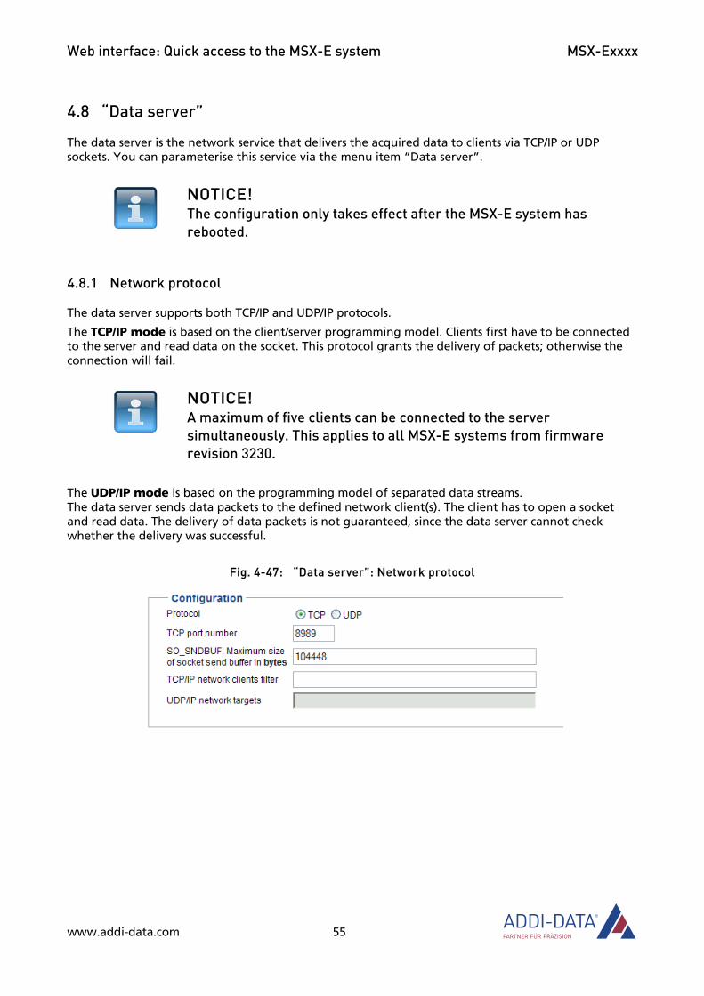
4.8.1 Network protocol
The data server supports both TCP/IP and UDP/IP protocols.
The TCP/IP mode is based on the client/server programming model. Clients first have to be connected to the server and read data on the socket. This protocol grants the delivery of packets; otherwise the connection will fail.
NOTICE! A maximum of five clients can be connected to the server simultaneously. This applies to all MSX-E systems from firmware revision 3230.
The UDP/IP mode is based on the programming model of separated data streams. The data server sends data packets to the defined network client(s). The client has to open a socket and read data. The delivery of data packets is not guaranteed, since the data server cannot check whether the delivery was successful.
Fig. 4-47: “Data server”: Network protocol
www.addi-data.com 55

Web interface: Quick access to the MSX-E system MSX-Exxxx
Fig. 4-48: “Data server”: Network protocol (new)
You have to specify UDP/IP clients for the data server in the “UDP/IP network targets” field. For this purpose, enter a string made up of IP address and port number which are separated by a space: “IP1:PORT1 IP2:PORT2 ... IPn:PORTn”. Example: “192.168.99.2:8080 192.168.99.3:8888”
4.8.2 “Blocking (TCP/IP) transfer” section or tab
In this mode, you can define a TCP/IP timeout in the form of “s.μs”.
Fig. 4-49: Data server: Blocking (TCP/IP) transfer
Fig. 4-50: Data server: Blocking (TCP/IP) transfer (new)
With the timeout value “1.0", the timeout is 1 second, i.e. the data server waits one second for a read confirmation from the data client. At the same time, the server blocks the reading of the acquired data. If it does not receive the client’s confirmation after one second, the connection to this client will be terminated. If it does, the server continues retrieving the acquired data. With the timeout value “0.0”, the server would permanently block the data, because it would wait constantly for a read confirmation from the data client.
If for “Activate blocking TCP/IP transfer?” the “Yes” option is selected, the throughput rate of the data server is reduced. However, this is an advantage in the event that the connection with the client is unexpectedly blocked. If the “No” option is selected, the actual TCP/IP timeout corresponds to the allowed minimum of the protocol. In this mode, network problems are identified in a better way than in “Yes” mode; moreover, the server throughput rate is higher.
www.addi-data.com 56
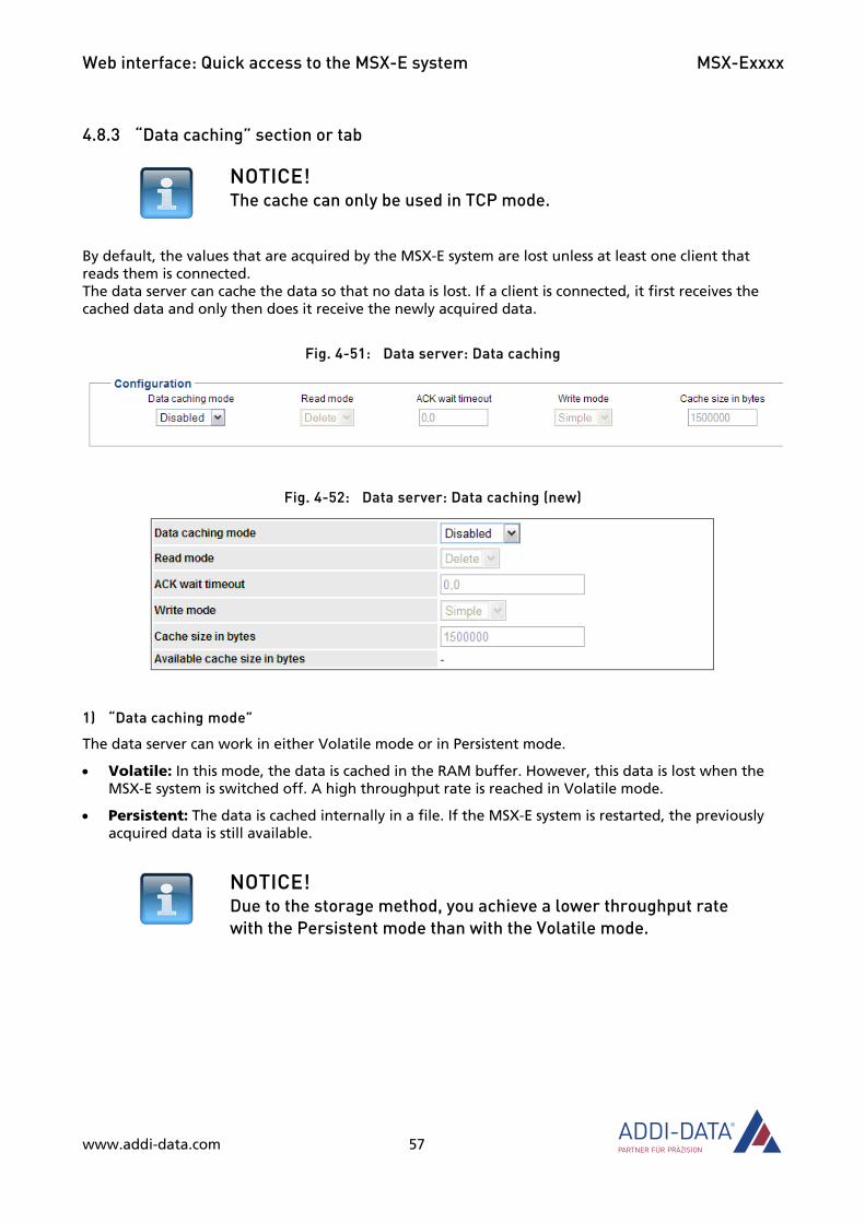
Web interface: Quick access to the MSX-E system MSX-Exxxx
4.8.3 “Data caching” section or tab
NOTICE! The cache can only be used in TCP mode.
By default, the values that are acquired by the MSX-E system are lost unless at least one client that reads them is connected. The data server can cache the data so that no data is lost. If a client is connected, it first receives the cached data and only then does it receive the newly acquired data.
Fig. 4-51: Data server: Data caching
Fig. 4-52: Data server: Data caching (new)
1) “Data caching mode”
The data server can work in either Volatile mode or in Persistent mode.
• Volatile: In this mode, the data is cached in the RAM buffer. However, this data is lost when the MSX-E system is switched off. A high throughput rate is reached in Volatile mode.
• Persistent: The data is cached internally in a file. If the MSX-E system is restarted, the previously acquired data is still available.
NOTICE! Due to the storage method, you achieve a lower throughput rate with the Persistent mode than with the Volatile mode.
www.addi-data.com 57
Web interface: Quick access to the MSX-E system MSX-Exxxx
2) “Read mode” (Read data from the cache)
The data server can delete or keep data if a client is connected.
• Delete mode: The cache is emptied when a client connects to the data server to retrieve data. Newly acquired data is not cached, but directly sent to the connected clients via the TCP/IP socket.
• Keep mode: Data is systematically cached. When a client connects to the data server, it first receives the cached data, which remains in the buffer though.
• ACK mode: This mode in which only one client can be connected provides for a confirmation management of the data in the application level. The cached data will only be deleted when the client has sent a confirmation (ACK command). In this mode, you can define a timeout for the confirmation command in the form of “s.μs”. If the server has not received the client’s confirmation within the defined time, the connection to this client is terminated. With the timeout value “0.0”, the server would permanently block the data, because it would wait constantly for a read confirmation from the data client.
3) “Write mode” (Write data into the cache)
The data server can work in Simple mode or in Circular mode. These modes define the procedures in the event of a cache overrun.
• Simple mode: Newly acquired values are ignored if the cache is full.
• Circular mode (ring buffer): If the cache is full, the oldest values are overwritten by the newest ones. If a client is connected, it receives the older values first.
www.addi-data.com 58
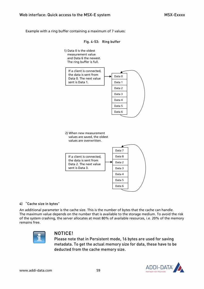
Web interface: Quick access to the MSX-E system MSX-Exxxx
www.addi-data.com 59
1) Data 0 is the oldest measurement value and Data 6 the newest. The ring buffer is full.
Data 0
Data 1
Data 2
Data 3
Data 4
Data 5
Data 6
If a client is connected, the data is sent from Data 0. The next value sent is Data 1.
2) When new measurement values are saved, the oldest values are overwritten.
Data 7
Data 8
Data 2
Data 3
Data 4
Data 5
Data 6
If a client is connected, the data is sent from Data 2. The next value sent is Data 3.
Example with a ring buffer containing a maximum of 7 values:
Fig. 4-53: Ring buffer
4) “Cache size in bytes”
An additional parameter is the cache size. This is the number of bytes that the cache can handle. The maximum value depends on the number that is available to the storage medium. To avoid the risk of the system crashing, the server allocates at most 80% of available resources, i.e. 20% of the memory remains free.
NOTICE! Please note that in Persistent mode, 16 bytes are used for saving metadata. To get the actual memory size for data, these have to be deducted from the cache memory size.

Web interface: Quick access to the MSX-E system MSX-Exxxx
4.8.4 Save and Restart
Fig. 4-54: Data server: What do you want to do?
Via the buttons in the section “What do you want to do?” (only previous web interface), the following actions can be performed:
• Save: The MSX-E system saves your new configuration. This is reused each time the MSX-E system starts.
• Reload: The web page with the configuration saved last is reloaded. Any changes that have not been saved will be lost.
• Restart: The data server is restarted.
• Restart & reset: The data server is restarted. If the data server has been configured in Persistent mode, the content of the cache file is deleted.
• Restart & delete: see the following note
NOTICE! If you have changed the configuration, you first have to save it by clicking on “Save” and then click on “Restart & delete” to restart the data server and to empty the cache.
4.9 “Modbus server”
On this web page or tab, you can configure the Modbus server of the MSX-E system, which provides SOAP-related functions. For more information, please also read Chapter 5.3. of this manual.
www.addi-data.com 60

Web interface: Quick access to the MSX-E system MSX-Exxxx
www.addi-data.com 61
4.10 Menu item “Extras” (new)
Fig. 4-55: Extras: Languages (new)
Via the menu item “Extras”, you can load and install a language package for translating the web interface.

Software MSX-Exxxx
5 Software Once you have configured your Ethernet system with the software tool ConfigTools (see Chapter 2), you can access it in one of the following ways:
• SOAP/web service
• Open Modbus (in combination with a PLC).
5.1 MSX-E system interface
Access to the MSX-E system is via a TCP/IP socket. The MSX-E system has three servers:
Table 5-1: MSX-E servers
Server Protocol Task Port No.
SOAP 5555 Command
server Open Modbus
Receive and process commands (acquisition,
initialisation, etc.) Little Endian = 215
Big Endian = 512
Data server TCP or UDP socket Data acquisition 8989
Event server TCP socket Event detection
(temperature warning, short-circuit)
6363
Fig. 5-1: Server overview
www.addi-data.com 62

Software MSX-Exxxx
5.2 Access via SOAP/web service
Via SOAP/web service access, all the functions of the MSX-E system are supported so that no specific software is required.
5.2.1 SOAP definition
The SOAP protocol (Simple Object Access Protocol) can be used to exchange data between systems and execute Remote Procedure Calls. SOAP works with the support of other standards, such as XML to display the data or with Internet protocols in the transport and application layer to transfer the messages. SOAP is most often used via HTTP and TCP.
Fig. 5-2: SOAP in the TCP/IP protocol stack
SOAP Application
HTTP HTTPS … Transport TCP
Network IP
Net access Ethernet Token Ring FDDI …
The bidirectional software interface to interprocess (IPC) or network communication is called socket. Sockets are a standardised interface (API) between the operating system and the actual application software.
5.2.2 SOAP functions
For a detailed description of the individual software functions, read the SOAP documentation of the respective Ethernet system (see MSX-E CD or driver download on the ADDI-DATA website).
5.3 Access via Open Modbus (for PLC)
The Open Modbus protocol is an open non-proprietary protocol based on the Modbus protocol.
The Modbus server enables an Ethernet system to be controlled by a PLC, e.g. a SIMATIC S7 from Siemens. The S7 PLC starts acquisitions and reads data from the Ethernet system. Detailed information on this can be found in the instruction manual “Ethernet I/O systems”.
NOTICE! Please note that only Modbus via TCP is standardised.
In addition to the standardised Modbus access via TCP, the MSX-E systems also allow for access via UDP sockets.
Please find more details about Modbus on the supplied CD “MSX-E Systems”.
www.addi-data.com 63

Software MSX-Exxxx
www.addi-data.com 64
5.4 Data server
The data server is used to transfer data (see also Chapter 4.8). The type and the format of this data are explained in more detail in the respective system-specific MSX-E manual.
5.5 Event server
The event server is a network service which informs the connected clients of events, i.e. state changes in subsystems. Clients are connected to the event server via a TCP/IP socket and receive change notifications in the form of packets. When a client is connected to an event server for the first time, it receives a packet with a summary of the current state of the MSX-E system. Every subsequent packet is associated with a change to a subsystem.
The event server can be used to call up diagnostic information, e.g. short-circuits.
5.5.1 Packet format
A packet contains a time stamp that indicates the time at which an event occurred.
Table 5-2: Event server: Packet format
Field Size (bytes)
0 (packet format version) 1
Number of subsequent bytes 1
Subsystem ID 1
New state ID 1
tv_sec 4
tv_usec 4
5.5.2 Time stamp format
The time stamp format is based on the UNIX convention for displaying time data. In the programming language C, for example, the time stamp is represented like this:
struct timeval { uint32_t tv_sec; /* seconds */ uint32_t tv_usec; /* microseconds */ };
The “tv_sec” field holds the number of seconds since the start of the UNIX era (1 January 1970). Accordingly, the “tv_usec” field holds the number of microseconds.

Return or disposal MSX-Exxxx
6 Return or disposal
6.1 Return
If you need to return your Ethernet system, you should read the following checklist before.
Checklist for returning the Ethernet system:
• Specify the reason for returning your Ethernet system (e.g. exchange, modification, repair), the serial number of the Ethernet system, the contact person in your company including his/her telephone extension and e-mail address, as well as the mailing address for a potential new delivery. You do not have to indicate the RMA number.
Fig. 6-1: Serial number
• Note down the serial number of the Ethernet system.
• Place the Ethernet system in an ESD protective cover. Then pack it in a cardboard box so that it is well-protected for shipping. Send the packed Ethernet system together with your details to:
ADDI-DATA GmbH Airpark Business Center Airport Boulevard B210 77836 Rheinmünster Germany
• If you have any questions, do not hesitate to contact us:
Phone: +49 7229 1847-0 E-mail: [email protected]
www.addi-data.com 65

Return or disposal MSX-Exxxx
www.addi-data.com 66
6.2 Disposal of ADDI-DATA waste equipment
ADDI-DATA organises the disposal of ADDI-DATA products that were put on the German market after 13 August 2005. If you want to return waste equipment, please e-mail your request to: [email protected].
Ethernet systems that were delivered after 13 August 2005 can be recognised by the following label:
Fig. 6-2: Disposal: Label
This symbol indicates the disposal of waste electrical and electronic equipment. It is valid in the European Union and in other European countries that have a separate collection system. Products carrying this symbol must not be treated as household waste. For more detailed information on the recycling of these products, please contact your local citizens’ office, your household waste collection service, the shop where you bought this product or the distributor you purchased this product from.
If you dispose of this product correctly, you will help to prevent damage that could be caused to the environment and to human health by inappropriate disposal. The recycling of materials will help to conserve our natural resources.
Disposal in other countries than Germany Please dispose of the product according to the country-specific regulations.
Appendix MSX-Exxxx
7 Appendix
7.1 Glossary
Buffer The buffer is used for the temporary storage of information that is only needed at a later time.
Cascading Cascading means connecting multiple similar elements together to enhance their individual effect. The individual elements must be such that the outputs of a given element are compatible with the inputs of the subsequent element in terms of values and functionality.
Data acquisition Data acquisition means gathering information from sources such as sensors and transducers in an accurate, timely and organised manner. Modern systems convert this information to digital data which can be stored and processed by a computer.
Driver A driver is a series of software instructions written specifically to manage particular devices.
ESD = Electrostatic Discharge
On non-conductive surfaces, an electric charge is conducted away very slowly. If the dielectric strength is overcome, there is a fast potential equalisation between the surfaces involved. The often very sudden equalisation process is referred to as electrostatic discharge (ESD). Currents of up to 20 A may occur in this process.
Ethernet The Ethernet is a baseband bus system originally developed in order to connect mini-computers. It is based on the CSMA/CD access method. Coaxial cables or twisted-pair cables are used as the transmission medium. The transmission speeds are 10 Mbit/s (Ethernet), 100 Mbit/s (Fast Ethernet) and 1 Gbit/s or 10 Gbit/s (Gigabit-Ethernet).
This widely used technology for computer networking in a LAN has been standardised since 1985 (IEEE 802.3 and ISO 8802-3). Ethernet technology is now common practice in the office environment. After making even very tough real-time requirements possible and adapting the device technology (bus cables, patch fields, junction boxes) to the harsh application conditions of the industrial environment, Ethernet is now also increasingly used in the field areas of automation technology.
Event An event is an occurrence detected by the MSX-E system. Where e. g. a short-circuit is detected and an event is activated, a short-circuit warning can be sent via the event server.
Ground line Ground lines should not be seen as potential-free return lines. Different ground points may have small potential differences. This is always true with large currents and may cause inaccuracy in high-resolution circuits.
MAC address MAC = Media Access Control
This is the hardware address of network components used to identify them uniquely within the network.
PLC = Programmable Logic Controller
The PLC is a computer-based control unit whose functionality is defined by an application program. With standardised technical languages, this application program is relatively easy to produce. Because of its serial mode of operation, reaction times of PLCs are slower than those of VPS. As a family of devices with graduated and matched components, PLCs can now cover all levels of an automation hierarchy.
www.addi-data.com 67

Appendix MSX-Exxxx
SOAP = Simple Object Process Protocol
SOAP is a simple extensible protocol for exchanging information in distributed environments. It defines XML messages that can be exchanged between heterogeneous applications via HTTP. SOAP is independent of operating systems and can be integrated into existing Internet structures, including Ethernet TCP/IP-based automation concepts. SOAP is based on Remote Procedure Calls and XML. This means that functions from other platforms can be called and used from any point within the network. Any results data can also be returned using XML schemas. This enables distributed computing capacity and non-redundant data storage in distributed systems.
TCP/IP = Transmission Control Protocol/Internet Protocol
TCP/IP is a family of network protocols and therefore often just referred to as Internet protocol. The computers that are part of the network are identified via their IP addresses. UDP is another transport protocol that belongs to the core group of this protocol family.
Trigger A trigger is a pulse or signal for starting or stopping a special task. Triggers are often used for controlling data acquisition.
UDP = User Datagram Protocol
This is a minimal connection-free network protocol which is part of the transport layer within the Internet protocol family. The purpose of UDPs is to ensure that data transmitted over the Internet reach the correct application.
www.addi-data.com 68

Appendix MSX-Exxxx
7.2 Index
Actuators 19 Autostart 53 Cascading 20 Commissioning 9 ConfigTools 24 Customer key 30 Date 30 Disposal 66 Function description
General functions 28 Glossary 67 Hardware trigger 28 LED display 21
Status LED 22 Modbus
Open Modbus 63 Server 60
Mounting 9 Angle bracket mounting 12 DIN rail mounting 11
Network Configuration 47 Diagnosis 46
Peripherals 18 Pin assignment 14
Ethernet 15 Power supply 17 Trigger/Synchro 16
PLC 63 Repair 65 Return 65 Sensors 19 Server
Overview 62 SOAP 63 Software 62 Synchronisation 29 Temperature monitoring 30 Time 30 Time stamp 30
Format 64 Type label 10 Web interface
Data server 55 Development Mode 54 Login 32 Navigation 33 Network 46 Security 40
www.addi-data.com 69

Contact and support MSX-Exxxx
8 Contact and support Do you have any questions? Write or call us: Address: ADDI-DATA GmbH Airpark Business Center Airport Boulevard B210 77836 Rheinmünster
Germany
Phone: +49 7229 1847-0 Fax: +49 7229 1847-222
E-mail: [email protected]
Manual and software download from the Internet:
www.addi-data.com
www.addi-data.com 70