technical diary- offshore 220mw barge mounted … mw barge technical diary short.pdf · technical...
TRANSCRIPT
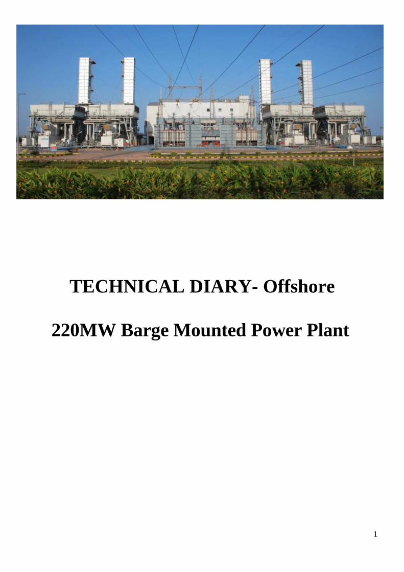
TECHNICAL DIARY- Offshore
220MW Barge Mounted Power Plant
1
Technical Diary - Offshore
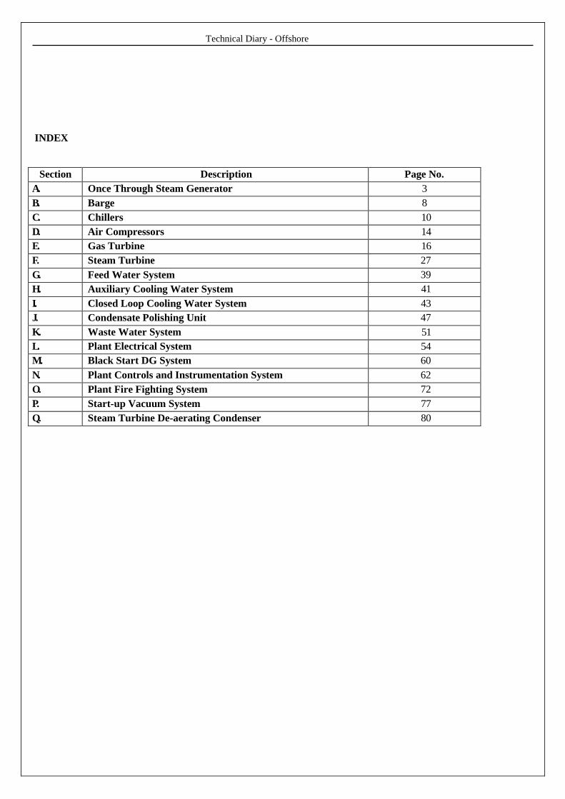
INDEX
Section Description Page No.
A. Once Through Steam Generator 3
B. Barge 8
C. Chillers 10
D. Air Compressors 14
E. Gas Turbine 16
F. Steam Turbine 27
G. Feed Water System 39
H. Auxiliary Cooling Water System 41
I. Closed Loop Cooling Water System 43
J. Condensate Polishing Unit 47
K. Waste Water System 51
L. Plant Electrical System 54
M. Black Start DG System 60
N. Plant Controls and Instrumentation System 62
O. Plant Fire Fighting System 72
P. Start-up Vacuum System 77
Q. Steam Turbine De-aerating Condenser 80

Technical Diary - Offshore
A. OTSG
Once Through Steam Generators also called OTSG are supplied by IST, Canada. These are the steam generators,
which generate steam for power generation in steam turbine. The heat in the exhaust gases from Gas Turbines is
transferred to feed water to generate steam at two pressures, HP & LP. The OTSG are drum less boilers having tube
bundles where steam is generated. Feed water is supplied to OTSG through feed water pumps after treating the water
in Condensate Polishing Unit. Suppling DM water to condenser hot well fulfils the additional makeup requirement.
The exhaust gases after giving their heat to feed water are let off to atmosphere through stack. The OTSG has a dry
running capability up to 560◦C.
General Specification:
Manufacture : INNOVATIVE STEAM TECHNOLOGIES
Type : ONCE THROUGH STEAM GENERATOR
Make No. :
Number of boilers : 4
Working Pr in psig / kg/cm2 (g) : HP - 865 / 59.62 &
LP - 68.3 / 4.71
Design pr in psig / kg/cm2 (g). : HP - 953 / 65.71 &
LP - 103 / 7.10
Hydraulic test pressure in psig / kg/cm2(g) : HP - 1884 / 129.87 &
LP - 384 / 26.47
Flue Gases : Gas Turbine exhaust flue gas
Capacity in lb/hr / kg/hr. : HP - 107600/48806.5 &
LP - 35570/16134.28
Design dry running gas temperature : 986 F
Maximum operating gas temperature : 856 F

Technical Diary - Offshore
B. BARGE
The Function of Barge is to contain and deliver 1(one) combined cycle barge mounted floating power plant of
nominal net capacity 220 MW, consisting of 4(four) Once Through Steam Generator (OSTG), 1(one) steam turbine
generator (STG), 4(four) combustion gas turbine generators and auxiliary equipment condensers, chilling system for
air intake and the remaining balance of plant. The basic design is to include the barge and the connections to
the mooring system, together with the power plant equipment.
The Design data of the barge
a) Barge size (length x wide x depth) : 106m x 55.2m x 6m
b) Barge draft for towing : 2.4 m (Normal operation 3.4m)
c) Total barge weight : 13,900tonnes
(barge itself including steam turbine hall, control building and above deck foundations: approximate 6,000 tonnes)
Stability
a) The barge is designed to comply with the intact stability regulation of US 46 CFR Chapter
I, Section 174.015 for river and harbor service.
b) The barge is designed to comply with the one compartment damage stability regulations of
US 46 CFR Chapter I, Section 172.065. The Barge shall comply with a wind heeling
moment as defined in CFR Chapter I, Section 174.055
c) The Barge is designed to comply with IMO International Convention on Load Lines
Barge Access
Four(4) ramps are designed to access the barge from shore,
one(1) main ramp 6m wide
one(1) ramp 4.5m and
two(2) auxiliary ramps 3.5m wide respectively.
Barge Ventilation
Below deck spaces are ventilated according to the recommended practices of SNAME T&R 4~16 “Calculation
Merchant Ship Heating, Ventilation and Air Condition Design”.
Fans are sized to limit the temperature rise in the ventilated spaces to be less than 5oC and to
Provide sufficient ventilation air to ensure noxious fumes are below accepted occupational
Safety regulation levels.

Technical Diary - Offshore
C. CHILLERS
Chillers are used to cool Gas Turbine intake air and enhancing the output of each Gas Turbine by 7 to 10 MW
approximately. The chillers operate on Vapour Compression Cycle. Chilled water is circulated through evaporator
where it rejects heat to refrigerant HFC134a and become chilled. This chilled water again picks up heat from gas
turbine intake air-cooling them. The boiled refrigerant is than compressor. The heat added to the refrigerant in
evaporator and compressor is that rejected in condenser, cooled by sea water. The motor is hermetically sealed. Lube
Oil and motor windings are cooled by refrigerant. Therefore heat from a low temperature source is rejected to high
temperature source.
Design criteria
1) Site conditionGT chiller coil required cooling capacity : 1200 USRT x 2 sets
2) GT chiller cooling coil design condition- Inlet air condition (Ambient) 37 ◦ DB / 75 % RH - Outlet air condition (GT inlet air) 7.22 ◦ DB / 95 % RH - GT inlet air flow rate 128.9 kg/s- Chilled water supply / return temp. 5 ◦c / 13.8 ◦c - Chilled water flow rate: 826 m3/h
Chilled water system consists with the following equipment,
Group 1.
Equipment No. Name Q‟ty Remarks
1. GT-1 Combustion air chilling coil #1 1 set 100%
2. GT-2 Combustion air chilling coil #2 1 set 100%
3. CS-M-CH01-1A Centrifugal Chiller #1A 1 set 50%
4. CS-M-CH01-1B Centrifugal Chiller #1B 1 set 50%
5. CS-M-CH01-2A Centrifugal Chiller #2A 1 set 50%
6. CS-M-CH01-2B Centrifugal Chiller #2B 1 set 50%
7. CS-M-PP01-1A Chilled water Circul. P/P #1A 1 set 50%
8. CS-M-PP01-1B Chilled water Circul. P/P #1B 1 set 50%
9. CS-M-PP01-2A Chilled water Circul. P/P #2A 1 set 50%
10.CS-M-PP01-2B Chilled water Circul. P/P #2B 1 set 50%
Technical Diary - Offshore
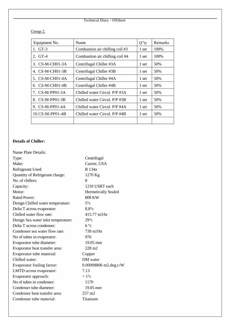
Group 2.
Equipment No. Name Q‟ty Remarks
1. GT-3 Combustion air chilling coil #3 1 set 100%
2. GT-4 Combustion air chilling coil #4 1 set 100%
3. CS-M-CH01-3A Centrifugal Chiller #3A 1 set 50%
4. CS-M-CH01-3B Centrifugal Chiller #3B 1 set 50%
5. CS-M-CH01-4A Centrifugal Chiller #4A 1 set 50%
6. CS-M-CH01-4B Centrifugal Chiller #4B 1 set 50%
7. CS-M-PP01-3A Chilled water Circul. P/P #3A 1 set 50%
8. CS-M-PP01-3B Chilled water Circul. P/P #3B 1 set 50%
9. CS-M-PP01-4A Chilled water Circul. P/P #4A 1 set 50%
10.CS-M-PP01-4B Chilled water Circul. P/P #4B 1 set 50%
Details of Chiller:
Name Plate Details:
Type: Centrifugal
Make: Carrier, USA
Refrigerant Used: R 134a
Quantity of Refrigerant charge: 1270 Kg
No. of chillers: 8
Capacity: 1210 USRT each
Motor: Hermetically Sealed
Rated Power: 808 KW
Design Chilled water temperature: 5°c
Delta T across evaporator: 8.8°c
Chilled water flow rate: 415.77 m3/hr
Design Sea water inlet temperature: 29°c
Delta T across condenser: 6 °c
Condenser sea water flow rate: 739 m3/hr
No of tubes in evaporator: 976
Evaporator tube diameter: 19.05 mm
Evaporator heat transfer area: 228 m2
Evaporator tube material: Copper
Chilled water: DM water
Evaporator fouling factor: 0.00008806 m2.deg.c/W
LMTD across evaporator: 7.13
Evaporator approach: > 1°c
No of tubes in condenser: 1170
Condenser tube diameter: 19.05 mm
Condenser heat transfer area: 257 m2
Condenser tube material: Titanium

Technical Diary - Offshore
Condenser fouling factor: 0.00008806 m2.deg.c/W
LMTD across evaporator: 3.08
Condenser approach: 1 to 2 ºc
Coefficient of Performance (COP): 5.2
Energy Efficiency: 0.192
Main motor: 6,600 V, 50 Hz, and 3 Ph
Aux. Power: 415 V, 50 Hz, 3 Ph
D. AIR COMPRESSOR
The plant instrument air and service air requirement are met through screw type air compressors located in barge
below deck compartments. There are 3 X 100 % compressors installed, having one instrument air receiver and one
service air receiver. The instrument air is passes through 2 X 100 % desiccant type dryers which dries the air for use in
instruments. The compressors are water cooled. To meets the equipment preservation air requirement and service air
requirement we have a onshore air compressors which is run when the plant is under shutdown. The air is routed
through the driers in barge to fulfil the requirement.
Specifications
Type rotary screw Oil free,
Make Water cooled screw type
Serial no TS 1703
Manufacturer Ingersoll Rand
Quantity 3 sets
Capacity 12.7Nm3/min
Pressure 8.64 bar g
Motor 120.4 kw/set
Compressor package data
Capacity 18 m3/min
Rated operating pressure 8.5 bar g
Max discharge pressure 8.7 bar g
Gross mass 3250 Kg
Total package amperes 218/209
Voltage 380/415 V
Phase/hertz 3/50
Serial no TS1701000126
Technical Diary - Offshore
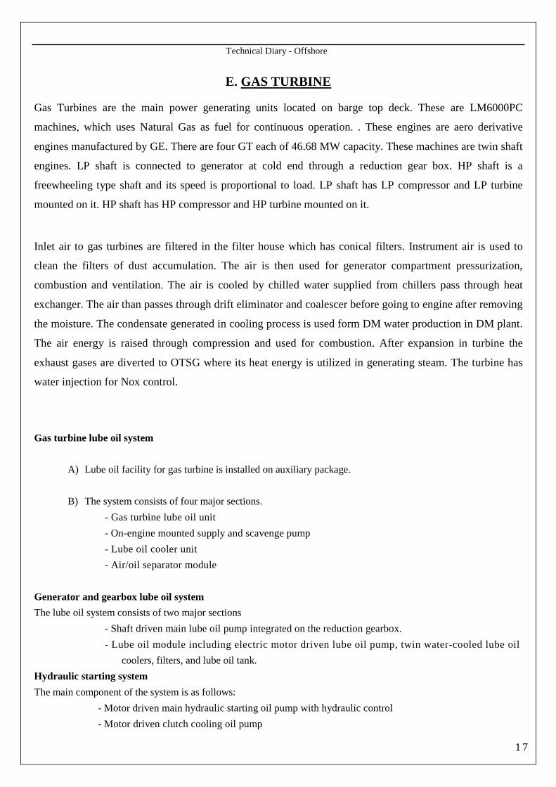
E. GAS TURBINE
Gas Turbines are the main power generating units located on barge top deck. These are LM6000PC
machines, which uses Natural Gas as fuel for continuous operation. . These engines are aero derivative
engines manufactured by GE. There are four GT each of 46.68 MW capacity. These machines are twin shaft
engines. LP shaft is connected to generator at cold end through a reduction gear box. HP shaft is a
freewheeling type shaft and its speed is proportional to load. LP shaft has LP compressor and LP turbine
mounted on it. HP shaft has HP compressor and HP turbine mounted on it.
Inlet air to gas turbines are filtered in the filter house which has conical filters. Instrument air is used to
clean the filters of dust accumulation. The air is then used for generator compartment pressurization,
combustion and ventilation. The air is cooled by chilled water supplied from chillers pass through heat
exchanger. The air than passes through drift eliminator and coalescer before going to engine after removing
the moisture. The condensate generated in cooling process is used form DM water production in DM plant.
The air energy is raised through compression and used for combustion. After expansion in turbine the
exhaust gases are diverted to OTSG where its heat energy is utilized in generating steam. The turbine has
water injection for Nox control.
Gas turbine lube oil system
A) Lube oil facility for gas turbine is installed on auxiliary package.
B) The system consists of four major sections.
- Gas turbine lube oil unit
- On-engine mounted supply and scavenge pump
- Lube oil cooler unit
- Air/oil separator module
Generator and gearbox lube oil system
The lube oil system consists of two major sections
- Shaft driven main lube oil pump integrated on the reduction gearbox.
- Lube oil module including electric motor driven lube oil pump, twin water-cooled lube oil
coolers, filters, and lube oil tank.
Hydraulic starting system
The main component of the system is as follows:
- Motor driven main hydraulic starting oil pump with hydraulic control
- Motor driven clutch cooling oil pump
1 7

Technical Diary - Offshore
- High and low pressure regulating valves
- Hydraulic starting oil tank
- Supply and return filters
- Hydraulic starter
- Hydraulic starting oil cooler
Air intake and exhaust gas system
Gas turbine inlet air is drawn through this filter house, and is led to the gas turbine inlet
through the air silencer and an inlet scroll assembly
Water washing system
The main components consisting system are as follows:
- Solution and rinse water tank
- AC motor driven pump
- Water wash filter
- Off-line water wash spray manifold (on-engine)
- On-line water wash spray manifold (on-engine)
Fire protection system
The fire protection system consists of CO2 bottle skid, related valves, pipe and Instrumentation.
- The CO2 is supplied to two places as follows,
- Gas turbine enclosure
- Generator rear bearing enclosure
Generator
A) The generator uses open air-cooled, synchronous type, and totally enclosed type.
B) T h e g e n e r a t o r w i l l b e a b l e t o h a n d l e a l l l o a d s i t u a t i o n s i n a s a t i s f a c t o r y
m a n n e r a t b o t h m a x i m u m a n d m i n i m u m a m b i e n t t e m p e r a t u r e . T h e g e n e r a t o r
c o n s i s t s o f t h e f o l l o w i n g c o m p o n e n t s :
(1) Rotor
(2) Stator
(3) Exciter
(4) Cooling system
(5) Frame & enclosure.
Technical Diary - Offshore
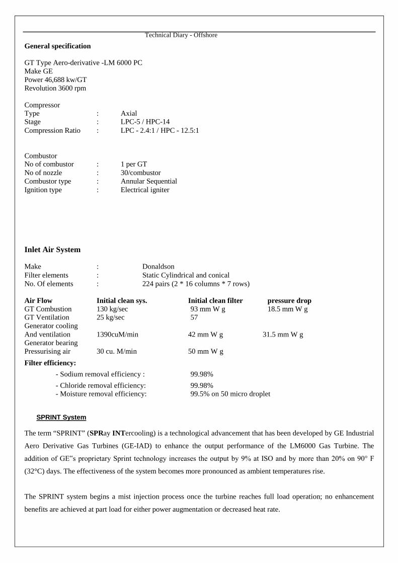
General specification
GT Type Aero-derivative -LM 6000 PCMake GEPower 46,688 kw/GTRevolution 3600 rpm
CompressorType : AxialStage : LPC-5 / HPC-14Compression Ratio : LPC - 2.4:1 / HPC - 12.5:1
CombustorNo of combustor : 1 per GTNo of nozzle : 30/combustorCombustor type : Annular SequentialIgnition type : Electrical igniter
Inlet Air System
Make : DonaldsonFilter elements : Static Cylindrical and conicalNo. Of elements : 224 pairs (2 * 16 columns * 7 rows)
Air Flow Initial clean sys. Initial clean filter pressure dropGT Combustion 130 kg/sec 93 mm W g 18.5 mm W gGT Ventilation 25 kg/sec 57Generator coolingAnd ventilation 1390cuM/min 42 mm W g 31.5 mm W gGenerator bearingPressurising air 30 cu. M/min 50 mm W g
Filter efficiency:
- Sodium removal efficiency : 99.98%
- Chloride removal efficiency: 99.98%- Moisture removal efficiency: 99.5% on 50 micro droplet
SPRINT System
The term “SPRINT” (SPRay INTercooling) is a technological advancement that has been developed by GE Industrial
Aero Derivative Gas Turbines (GE-IAD) to enhance the output performance of the LM6000 Gas Turbine. The
addition of GE‟s proprietary Sprint technology increases the output by 9% at ISO and by more than 20% on 90° F
(32°C) days. The effectiveness of the system becomes more pronounced as ambient temperatures rise.
The SPRINT system begins a mist injection process once the turbine reaches full load operation; no enhancement
benefits are achieved at part load for either power augmentation or decreased heat rate.

Technical Diary - Offshore
The SPRINT cooling technology lowers the high-pressure compressor (HPC) inlet temperature (T2.5), which in turn
effectively lowers the HPC compressor discharge temperature (T3).
ISO-International Standards Organization
Ambient temperature 59 F (15 C)
Barometric pressure 14.6% (101.4 kPa)
Relative humidity 60%
Elevation sea level
Inlet and exhaust losses-none
Emission controls-none
The system consists of two multi-nozzle inter stage mist injection systems
1) The low-pressure compressor (LPC) mist injection system consists of a single row of 23 nozzles located in the
inlet of the LPC.
2) The high-pressure compressor (HPC) manifold is split into two (2) separate manifolds (inner / outer)
consisting of two rows of 12 nozzles each for a combined total of 24 nozzles. The HPC manifolds are located
in the compressor front frame support housing between the LPC and HPC.
Only one manifold will be operational at a given time. Which manifold is energized is dependent on the inlet air
temperature. Inlet air temperatures of ≥ 48°F enables the LPC SOV valve to be opened when the system is enabled.
When temperature drop below 48°F the LPC manifold will be de-energized and HPC manifold energized. If the
temperature continues to drop, at 41°F both HPC and LPC will be de- energized. As temperatures increase from below
41°F the HPC manifold will be reenergized at 43°F increasing and at 50°F increasing the LPC manifold will be
reenergized and HPC manifold de-energized.
Air extracted from the engine 8th stage HPC bleed air extraction port is utilized to atomize & pressurize the system By
using the SPRINT spray inter-cooling system, the compressor pressure ratio can be increased and additional air can be
directed through the compressor to increase the gas turbine characteristics
Specifications
Pump Type : Vertical Multi Stage Centrifugal Pump
Material : Stainless Steel
Catalogue No : 3SVDK15SCP
Pressure : P SI 360 max
Temperature : 250 F Max
Manufacturer : Goulds Pumps , ITT , G&L Services SSV
Flow Range : 1 1 to 75 gpm
Pump Efficiency : 65%
Motor Power : 3/4 HP
2 0

Technical Diary - Offshore
Filter
Type : Duplex
Manufacturer : Indufil BV, Netherland
Year : 2007
Skid Mounted Equipment
Demineralised water is supplied to the SPRINT system from DM plant. It is supplied at a rate of 10-gpm minimum
to 30 gpm maximum and at pressures 0-65 psig. After interface connection, it flows through a Y-type strainer, a
normally open ball valve to a centrifugal pump . The centrifugal pump is driven by motor rated at 10 HP. After the
pump, the demineralised water pressure is monitored by pressure switch LOW PSL-62227 which activates pressure
alarm LOW PAL- 62227 in the event the water pressure falls below 75 psig. Pressure gauge PI-62229 scaled 0-400
psig displays pump discharge pressure .The demineralised water then flows through a flow meter, solenoid actuated
block valve, and enters a duplex filter that filters the water to 20 microns absolute. Pressure differential switch
HIGH PDSH-62233 monitors the differential pressure across the filters and activates an alarm should the
differential pressure increase to 10 psid. Pressure differential indicator PDI-62232 provides a visual display of the
differential pressure across the filter.
LPC SPRINT – 17 gpm (64 L/Min)
HPC SPRINT – 13 gpm (50 L/Min), 6.5 gpm (25 L/Min)per manifold
System Pressurization Air
Air for atomizing and pressurizing the SPRINT system is extracted from the 8th stage HPC at engine. The air is
supplied at 630 scfm (18 SCMM) and 150 psia (1034 KPaG) through an orifice. The air flow is divided into two
separate flow one for LP SPRINT and the other for HP SPRINT.
System purge air is used to purge demineralized water from the system for approximately two minutes immediately
after SPRINT shutdown. This is conducted to prevent corrosion and the possibility of ice formation. System purge air
is provided from the customer‟s connection at 80-120 psig, dry filtered to 5 microns absolute.
Fuel Injection System
Type: Gas Fuel System with Nox Injection
The LM6000 PC fuel system includes fuel manifolds, flexible fuel hoses, and 30 fuel Nozzles. The minimum
temperature of the gas fuel supplied to the gas turbine shall be 50°F (27.8°C) greater than the saturated vapour
temperature of the gas supply pressure. The temperature of the gas fuel should not exceed 300°F (148.8°C) at the gas
manifold inlet
Technical Diary - Offshore
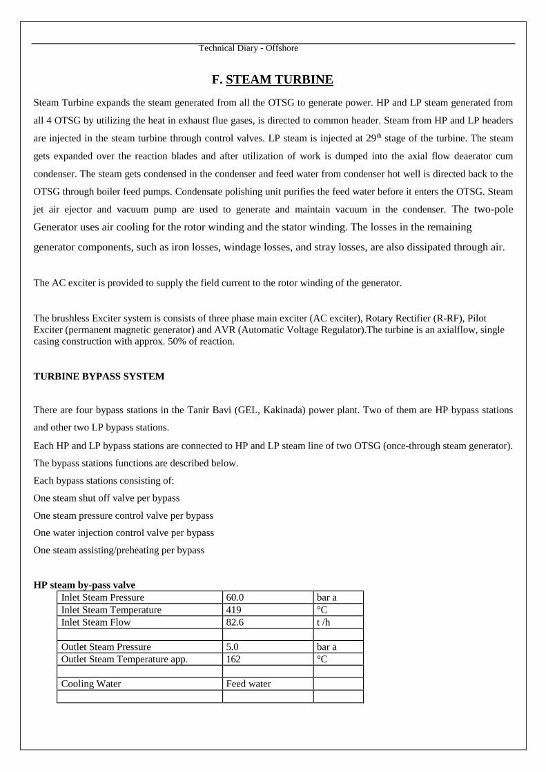
F. STEAM TURBINE
Steam Turbine expands the steam generated from all the OTSG to generate power. HP and LP steam generated from
all 4 OTSG by utilizing the heat in exhaust flue gases, is directed to common header. Steam from HP and LP headers
are injected in the steam turbine through control valves. LP steam is injected at 29th stage of the turbine. The steam
gets expanded over the reaction blades and after utilization of work is dumped into the axial flow deaerator cum
condenser. The steam gets condensed in the condenser and feed water from condenser hot well is directed back to the
OTSG through boiler feed pumps. Condensate polishing unit purifies the feed water before it enters the OTSG. Steam
jet air ejector and vacuum pump are used to generate and maintain vacuum in the condenser. The two-pole
Generator uses air cooling for the rotor winding and the stator winding. The losses in the remaining
generator components, such as iron losses, windage losses, and stray losses, are also dissipated through air.
The AC exciter is provided to supply the field current to the rotor winding of the generator.
The brushless Exciter system is consists of three phase main exciter (AC exciter), Rotary Rectifier (R-RF), PilotExciter (permanent magnetic generator) and AVR (Automatic Voltage Regulator).The turbine is an axialflow, singlecasing construction with approx. 50% of reaction.
TURBINE BYPASS SYSTEM
There are four bypass stations in the Tanir Bavi (GEL, Kakinada) power plant. Two of them are HP bypass stations
and other two LP bypass stations.
Each HP and LP bypass stations are connected to HP and LP steam line of two OTSG (once-through steam generator).
The bypass stations functions are described below.
Each bypass stations consisting of:
One steam shut off valve per bypass
One steam pressure control valve per bypass
One water injection control valve per bypass
One steam assisting/preheating per bypass
HP steam by-pass valveInlet Steam Pressure 60.0 bar aInlet Steam Temperature 419 °CInlet Steam Flow 82.6 t /h
Outlet Steam Pressure 5.0 bar aOutlet Steam Temperature app. 162 °C
Cooling Water Feed water
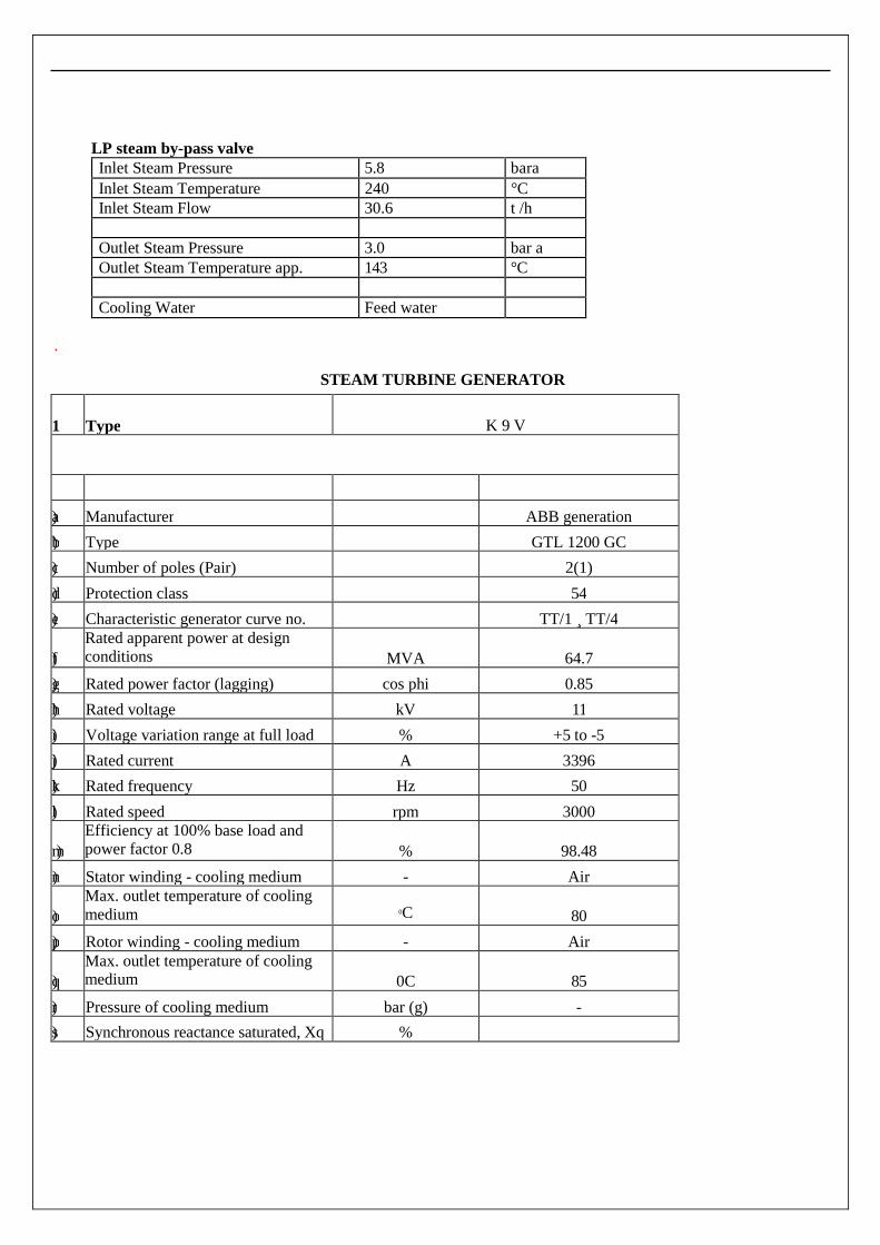
LP steam by-pass valveInlet Steam Pressure 5.8 bara
Inlet Steam Temperature 240 °CInlet Steam Flow 30.6 t /h
Outlet Steam Pressure 3.0 bar aOutlet Steam Temperature app. 143 °C
Cooling Water Feed water
.
STEAM TURBINE GENERATOR
1 Type K 9 V
a) Manufacturer ABB generation
b) Type GTL 1200 GC
c) Number of poles (Pair) 2(1)
d) Protection class 54
e) Characteristic generator curve no. TT/1 ¸ TT/4
f)
Rated apparent power at designconditions MVA 64.7
g) Rated power factor (lagging) cos phi 0.85
h) Rated voltage kV 11
i) Voltage variation range at full load % +5 to -5
j) Rated current A 3396
k) Rated frequency Hz 50
l) Rated speed rpm 3000
m)
Efficiency at 100% base load andpower factor 0.8 % 98.48
n) Stator winding - cooling medium - Air
o)Max. outlet temperature of coolingmedium 0C 80
p) Rotor winding - cooling medium - Air
q)Max. outlet temperature of coolingmedium 0C 85
r) Pressure of cooling medium bar (g) -
s) Synchronous reactance saturated, Xq %
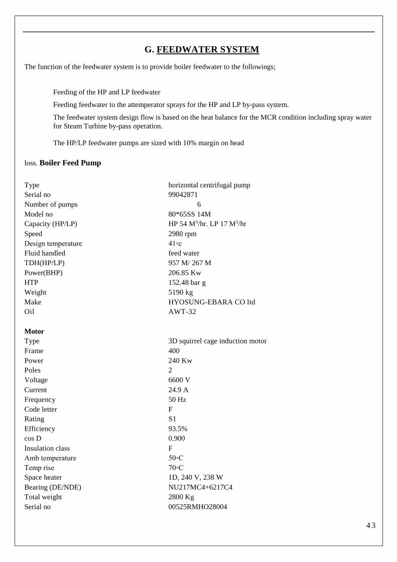
G. FEEDWATER SYSTEM
The function of the feedwater system is to provide boiler feedwater to the followings;
Feeding of the HP and LP feedwater
Feeding feedwater to the attemperator sprays for the HP and LP by-pass system.
The feedwater system design flow is based on the heat balance for the MCR condition including spray waterfor Steam Turbine by-pass operation.
The HP/LP feedwater pumps are sized with 10% margin on head
loss. Boiler Feed Pump
Type horizontal centrifugal pump
Serial no 99042871
Number of pumps 6
Model no 80*65SS 14M
Capacity (HP/LP) HP 54 M3/hr. LP 17 M3/hr
Speed 2980 rpm
Design temperature 41◦c
Fluid handled feed water
TDH(HP/LP) 957 M/ 267 M
Power(BHP) 206.85 Kw
HTP 152.48 bar g
Weight 5190 kg
Make HYOSUNG-EBARA CO ltd
Oil AWT-32
Motor
Type 3D squirrel cage induction motor
Frame 400
Power 240 Kw
Poles 2
Voltage 6600 V
Current 24.9 A
Frequency 50 Hz
Code letter F
Rating S1
Efficiency 93.5%
cos D 0.900
Insulation class F
Amb temperature 50◦C
Temp rise 70◦C
Space heater 1D, 240 V, 238 W
Bearing (DE/NDE) NU217MC4+6217C4
Total weight 2800 Kg
Serial no 00525RMHO28004
4 3

Technical Diary - Offshore
Manufacturing date 2000, 06
Make HYUNDAI
Ammonia/ Hydrazine dosing
Ammonia solution tank
Type vertical cylindrical
Capacity 300 L
Hydrazine solution tank
Type vertical cylindrical
Capacity 300 L
Ammonia dosing pump
Type metering pump
Capacity 5.0 L/hr @ 20.7 bar g
Make LIQUID DYNAMICS
M.A.W.P 3000 bar at 100◦C
MIN.D. metal temp 20 F
Serial no 024477
Seal material E.MAX 170 F MIM -50 F
Membrane material E.MAX 170 F MIM -50 F
Recommended refill pressure 2400 Psi
Agitator
Model 8641-99
Power 0.25 HP
Voltage 240 V
FLA 2.4
INS class F
Enc TEFC
Frame 56C
Duty continuous
Speed 960 rpm
Frequency 50 Hz
SF 1.0
Max Ambient 50◦C
Bearing 6023
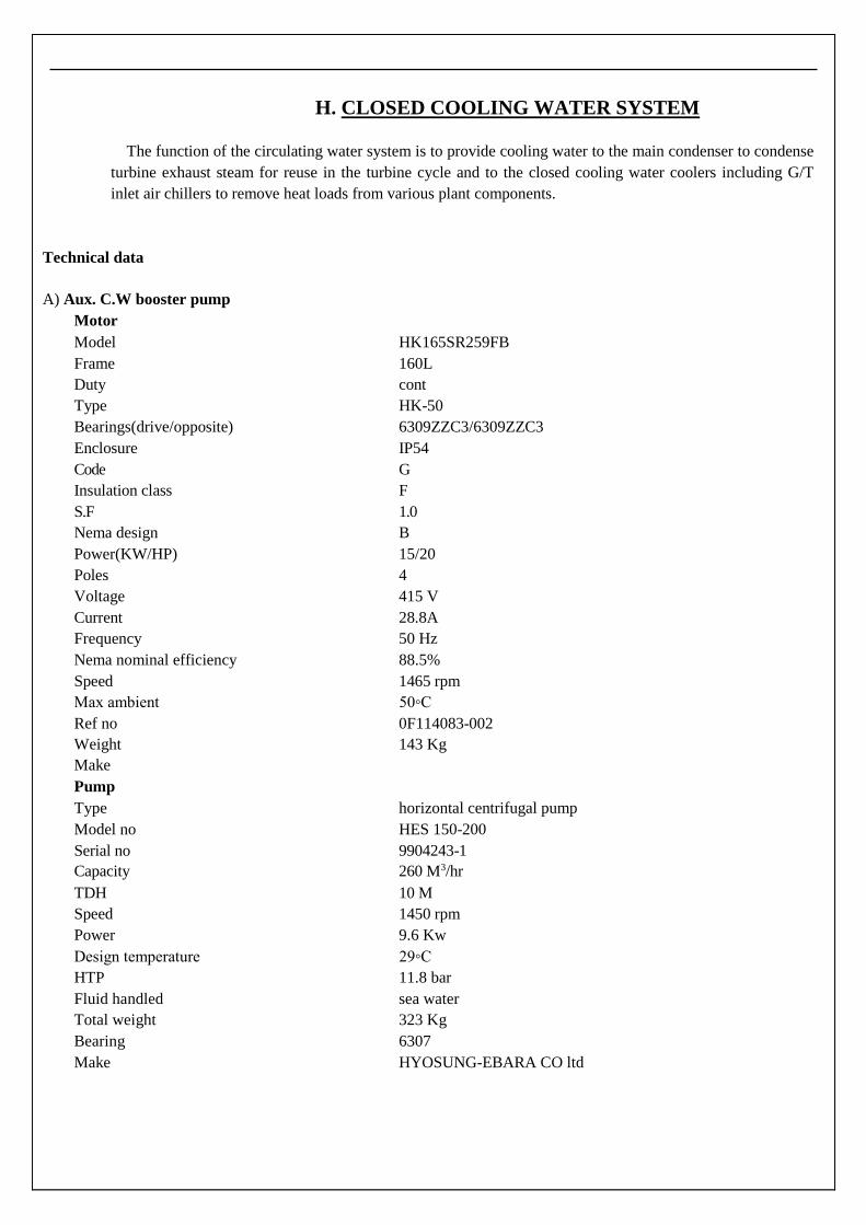
H. CLOSED COOLING WATER SYSTEM
The function of the circulating water system is to provide cooling water to the main condenser to condense
turbine exhaust steam for reuse in the turbine cycle and to the closed cooling water coolers including G/T
inlet air chillers to remove heat loads from various plant components.
Technical data
A) Aux. C.W booster pump
Motor
Model HK165SR259FB
Frame 160L
Duty cont
Type HK-50
Bearings(drive/opposite) 6309ZZC3/6309ZZC3
Enclosure IP54
Code G
Insulation class F
S.F 1.0
Nema design B
Power(KW/HP) 15/20
Poles 4
Voltage 415 V
Current 28.8A
Frequency 50 Hz
Nema nominal efficiency 88.5%
Speed 1465 rpm
Max ambient 50◦C
Ref no 0F114083-002
Weight 143 Kg
Make
Pump
Type horizontal centrifugal pump
Model no HES 150-200
Serial no 9904243-1
Capacity 260 M3/hr
TDH 10 M
Speed 1450 rpm
Power 9.6 Kw
Design temperature 29◦C
HTP 11.8 bar
Fluid handled sea water
Total weight 323 Kg
Bearing 6307
Make HYOSUNG-EBARA CO ltd
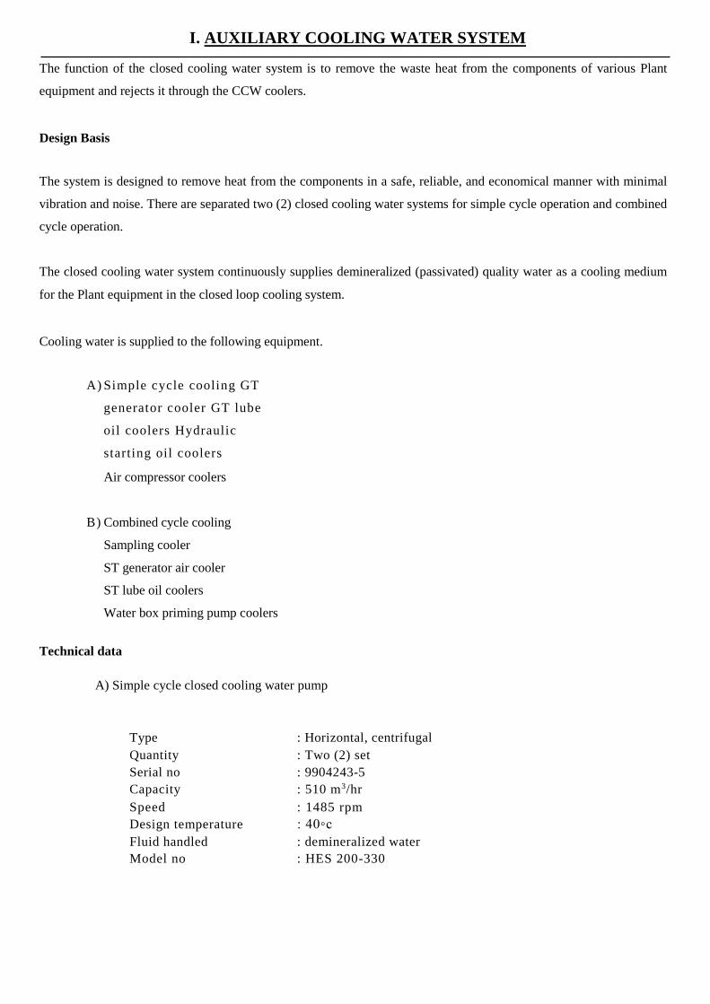
I. AUXILIARY COOLING WATER SYSTEM
The function of the closed cooling water system is to remove the waste heat from the components of various Plant
equipment and rejects it through the CCW coolers.
Design Basis
The system is designed to remove heat from the components in a safe, reliable, and economical manner with minimal
vibration and noise. There are separated two (2) closed cooling water systems for simple cycle operation and combined
cycle operation.
The closed cooling water system continuously supplies demineralized (passivated) quality water as a cooling medium
for the Plant equipment in the closed loop cooling system.
Cooling water is supplied to the following equipment.
A) Simple cycle cooling GT
generator cooler GT lube
oil coolers Hydraulic
starting oil coolers
Air compressor coolers
B) Combined cycle cooling
Sampling cooler
ST generator air cooler
ST lube oil coolers
Water box priming pump coolers
Technical data
A) Simple cycle closed cooling water pump
Type : Horizontal, centrifugal
Quantity : Two (2) set
Serial no : 9904243-5
Capacity : 510 m3/hr
Speed : 1485 rpm
Design temperature : 40◦c
Fluid handled : demineralized water
Model no : HES 200-330
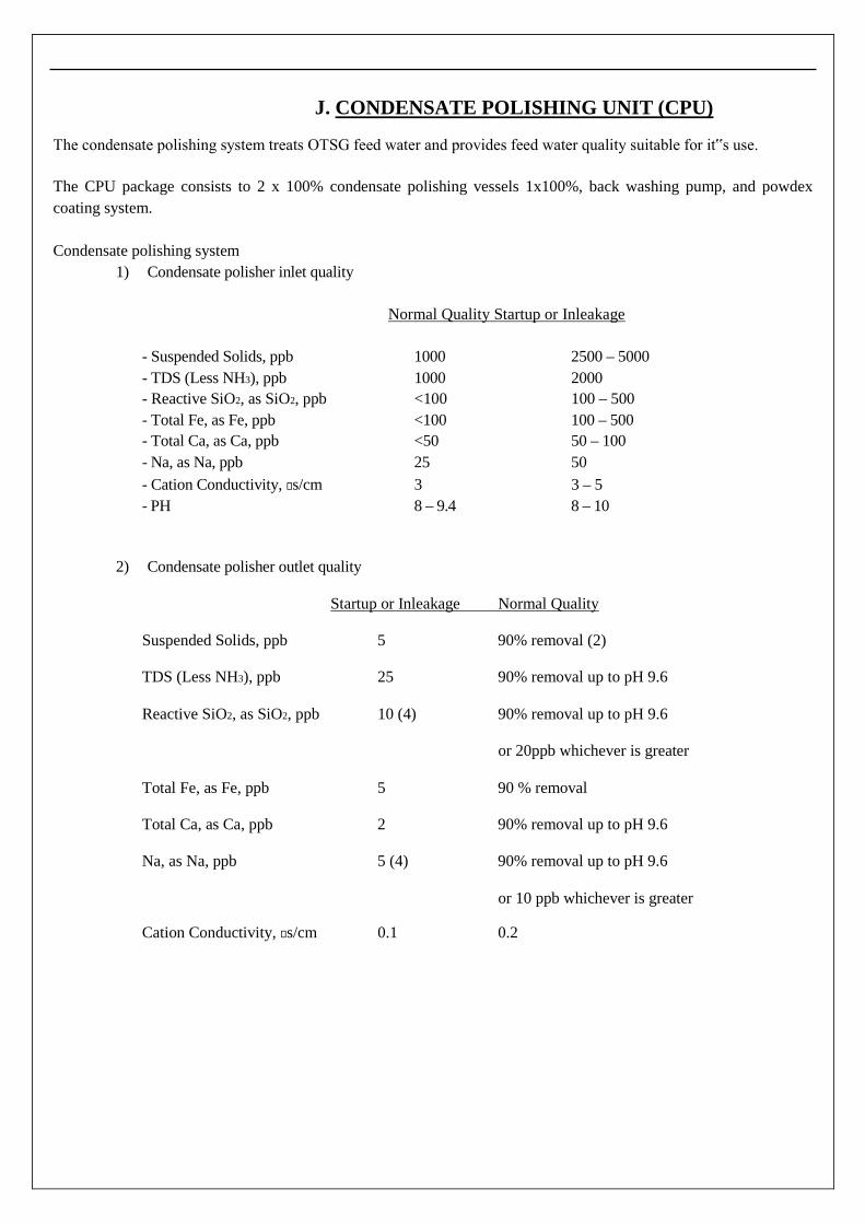
J. CONDENSATE POLISHING UNIT (CPU)
The condensate polishing system treats OTSG feed water and provides feed water quality suitable for it‟s use.
The CPU package consists to 2 x 100% condensate polishing vessels 1x100%, back washing pump, and powdex
coating system.
Condensate polishing system
1) Condensate polisher inlet quality
Normal Quality Startup or Inleakage
- Suspended Solids, ppb 1000 2500 – 5000
- TDS (Less NH3), ppb 1000 2000
- Reactive SiO2, as SiO2, ppb <100 100 – 500
- Total Fe, as Fe, ppb <100 100 – 500
- Total Ca, as Ca, ppb <50 50 – 100
- Na, as Na, ppb 25 50
- Cation Conductivity, s/cm 3 3 – 5
- PH 8 – 9.4 8 – 10
2) Condensate polisher outlet quality
Startup or Inleakage Normal Quality
Suspended Solids, ppb 5 90% removal (2)
TDS (Less NH3), ppb 25 90% removal up to pH 9.6
Reactive SiO2, as SiO2, ppb 10 (4) 90% removal up to pH 9.6
or 20ppb whichever is greater
Total Fe, as Fe, ppb 5 90 % removal
Total Ca, as Ca, ppb 2 90% removal up to pH 9.6
Na, as Na, ppb 5 (4) 90% removal up to pH 9.6
or 10 ppb whichever is greater
Cation Conductivity, s/cm 0.1 0.2
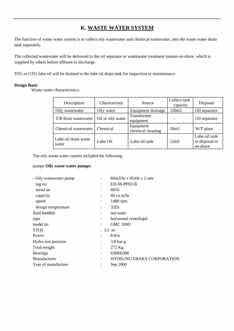
K. WASTE WATER SYSTEM
The function of waste water system is to collect oily wastewater and chemical wastewater, into the waste water drain
tank separately.
The collected wastewater will be delivered to the oil separator or wastewater treatment system on-shore, which is
supplied by others before effluent to discharge.
STG or GTG lube oil will be drained to the lube oil drain tank for inspection or maintenance.
Design BasisWaste water characteristics.
Description Characteristic SourceCollect tank
capacity Disposal
Oily wastewater Oily water Equipment drainage 120m3 Oil separator
T/R drain wastewater Oil or oily waterTransformerequipment
- Oil separator
Chemical wastewater ChemicalEquipmentchemical cleaning 50m3 W/T plant
Lube oil drain wastewater
Lube Oil Lube oil tank 12m3Lube oil tankor disposal toon-shore
The oily waste water system included the following
pumps Oily waste water pumps:
- Oily wastewater pump : 60m3/hr x 45mh x 2 sets
tag no : ED-M-PP02-B
serial no : 6050
capacity : 60 cu.m/hr
speed : 1480 rpm
design temperature : 32c
fluid handled : sea water
type : horizontal centrifugal
model no : GMC 100D
T D H : 3 2 mPower : 8 Kw
Hydro test pressure : 3.8 bar g
Total weight : 272 Kg
Bearings : 6308/6308
Manufacturer : HYOSUNG EBARA CORPORATION
Year of manufacture : Sep 2000

L. PLANT ELECTRICAL SYSTEM
The plant generates power at 11KV and evacuates power to 220kV switchyard from each of generator step-
up transformer on barge through over-headlines. There are three step up transformers
1. GST#1- 11KV/11KV/220KV-120MVA Three winding transformer
2. GST#2-11KV/11KV/220KV -120 MVA Three winding transformer
3. SST -11KV/220KV -70MVA Two winding transformer
GST is three winding transformer with input from two gas turbine generator at LV side (11KV) and output at
HV side (220KV). SST is two winding transformer with Input from steam turbine generator at 11KV side
and output of 220KV at HV side.
Also the 11KV is stepped down to 6.6KV through Unit Auxiliary transformers UAT#1 and UAT#2 for the plant
auxiliary power. 6.6KV is used for running the Boiler feeder pumps and chillers during plant operation and also
stepped down to 415V through Auxiliary transformers AT#1, AT#2, AT#3 and AT #4 for the plant auxiliary.
Design Criteria
The system parameters for utility are detailed below
System Fault level System Earthling
220kV, 50Hz, 3ph, 3wire 31.5kA/1sec Solid earthling (BIL;950kV)
11.0kV, 50Hz, 3ph, 3wire
6.6kV, 50Hz,3ph, 3wire
415V, 50Hz, 3ph, 4wire
50kA/3sec
20kA/1sec
50kA/1sec
Neutral earthedthrough NGTR(<10A)Low Resistancethrough NGR (1200A)Solid earthling
The system/equipment are designed as per the following:
Motors/System Voltage System Earthing
Motors above200kW 6.6kV Low Resistance
Motors 1kWup to 200KW 415V SolidMotors below1KW 240V SolidControls for MCC UPS 110VAC Solidsupply Illumination 110VAC EarthedSystem 240VAC SolidSpace heater for panel 240VAC Solid/motor 55kw& aboveDC system 110VDC Unearthed

M.V Switchgear
M.V switchgear is composed of vacuum circuit breaker (VCB) for 6.6KV motors and power feeding to 415V common
Technical Diary - Offshore
MCC and on-shore, control/metering instruments, integrated digital relays for protection, etc.
L.V switchgear is composed of four (4) common MCC, each of them having incoming air circuit breaker (ACB),
MCCB for outgoing feeders, control/metering instruments, etc.
DC / UPS system
Battery backed D.C system consisted of redundant battery chargers and two battery banks are provided.
For critical loads redundant feeders with auto-changeover scheme is provided.
Some of the loads also require a secure A.C supply for its operation. For these loads, station DC fed inverter system,
generally known as uninterrupted power supply (UPS) is provided for the followings;
- DCS
- Communication system
- Control, protection system etc.
Lighting system
Lighting system is designed to provide appropriate illumination for the plant in all times considering the nature of
work to be carried out.
The power supply for lighting systems shall be derived from the following sources.
- Normal A.C system
- Emergency lighting system (DC)
- Battery backed exit lighting
Fluorescent lamps are used for offices, switchgear room, etc. High-pressure sodium vapor lamps & metal halide and
LED lamps shall be used for high bay indoor area and outdoor area respectively as appropriate.
Grounding & lightning protection
The grounding & lightning system in general cover the followings;
- System neutral grounding
- Equipment grounding for personnel safety
- Lightning protection
All metallic, non-current carrying parts of all apparatus such as transformers, switchgear panels, control & protection
panels, cable trays, crane rails, steel structures, etc. are bounded with grounding system.
Power supply to on-shore
For on-shore plant, the followings are provided from the barge;
6.6KV redundant feeders through interconnecting cable support
415V emergency power in redundant feeders through interconnecting cable support5 9

Power Transformers GST 1 & GST 2
Rating : 3 phase / 120 MVA
Voltage : 220/11/11 KV
Capacity HV/LV1/LV2 : 120/60/60
Cooling : ONAN/ONAF
BIL (KVP) : 1050/75/75
Frequency : 50 HZ
Connection & Symbol : Star/Delta/Delta – Ynd11d11
Neutral Grounding : HV solidly grounded
Type of Conservator : Air Cell type (COPS)
Type of tank : Conventional type with bolted cover
Type of tap changer : Off Circuit tapping switch
Cooling Equipments : Radiator with fans
Type of bushing : HV – 245 KV OIP Condenser bushing
LV 1 & LV 2 – 17.5 KV Porcelain bushing
HV neutral – 36 KV porcelain bushing
No load loss : 90 KW
No load current : 1 %
Noise level : 85 dB
Load losses : 340 KW
Temperature rise : Oil – 35 deg.c & Winding – 45 deg.c
Voltage variation : + 5 to – 5 % of HV – Switch
Power Transformer SST
Rating : 3 phase / 70 MVA
Voltage : 220/11 KV
Capacity HV/LV : 70
Cooling : ONAN/ONAF
BIL (KVP) : 1050/75
Frequency : 50 HZ
Connection & Symbol : Star/Delta – Ynd11
Neutral Grounding : HV solidly grounded
Type of Conservator : Air Cell type (COPS)
Type of tank : Conventional type with bolted cover
Type of tap changer : Off Circuit tapping switch
Cooling Equipments : Radiator with fans
Type of bushing : HV – 245 KV OIP Condenser bushing
LV – 17.5 KV Porcelain bushing
HV neutral – 36 KV porcelain bushing
No load loss : 46 KW
No load current : 1 %
Noise level : 85 dB
Load losses : 260 KW
Temperature rise : Oil – 35 deg.c & Winding – 45 deg.c
Voltage variation : + 5 to – 5 % of HV – Switch
6 0
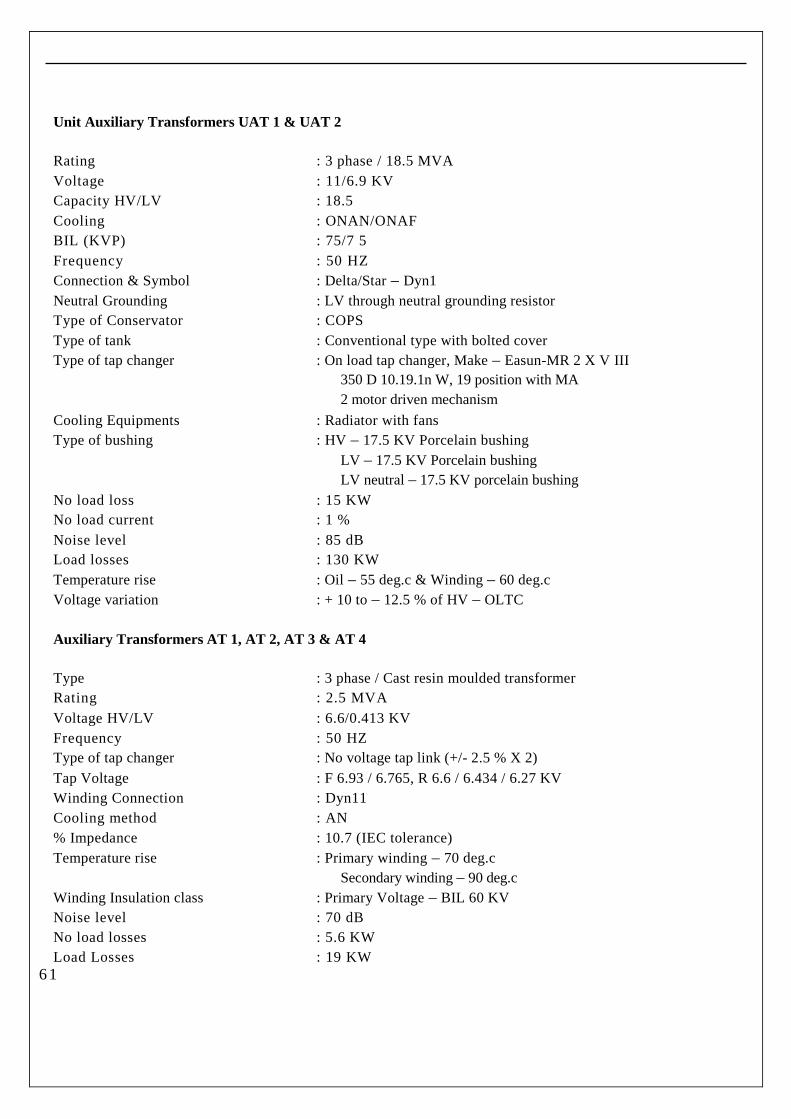
Unit Auxiliary Transformers UAT 1 & UAT 2
Rating : 3 phase / 18.5 MVA
Voltage : 11/6.9 KV
Capacity HV/LV : 18.5
Cooling : ONAN/ONAF
BIL (KVP) : 75/7 5
Frequency : 50 HZ
Connection & Symbol : Delta/Star – Dyn1
Neutral Grounding : LV through neutral grounding resistor
Type of Conservator : COPS
Type of tank : Conventional type with bolted cover
Type of tap changer : On load tap changer, Make – Easun-MR 2 X V III
350 D 10.19.1n W, 19 position with MA
2 motor driven mechanism
Cooling Equipments : Radiator with fans
Type of bushing : HV – 17.5 KV Porcelain bushing
LV – 17.5 KV Porcelain bushing
LV neutral – 17.5 KV porcelain bushing
No load loss : 15 KW
No load current : 1 %
Noise level : 85 dB
Load losses : 130 KW
Temperature rise : Oil – 55 deg.c & Winding – 60 deg.c
Voltage variation : + 10 to – 12.5 % of HV – OLTC
Auxiliary Transformers AT 1, AT 2, AT 3 & AT 4
Type : 3 phase / Cast resin moulded transformer
Rating : 2.5 MVA
Voltage HV/LV : 6.6/0.413 KV
Frequency : 50 HZ
Type of tap changer : No voltage tap link (+/- 2.5 % X 2)
Tap Voltage : F 6.93 / 6.765, R 6.6 / 6.434 / 6.27 KV
Winding Connection : Dyn11
Cooling method : AN
% Impedance : 10.7 (IEC tolerance)
Temperature rise : Primary winding – 70 deg.c
Secondary winding – 90 deg.c
Winding Insulation class : Primary Voltage – BIL 60 KV
Noise level : 70 dB
No load losses : 5.6 KW
Load Losses : 19 KW6 1

List of Onshore and Offshore AC Equipments
Location Total no Each capacity
Totalcapacity in
TRType Make
1 Barge control room 1 8 8 package CARRIER
2 Rack room 2 8,11 19 package CARRIER,BLUE STAR
3 Roof top 1 20 20 package CARRIER
4 Remote i/o panel 4 2 8 ducting split BLUE STAR
5 Pump house -PLC 1 2 2 split VOLTAS
6 Switch yard 3 2 6 split VOLTAS
7Work shopbuilding(mech) 1 2 2 split VOLTAS
8 DM plant 3 2 6 split VOLTAS
9 Ware house 3 2 6 split VOLTAS
10 Security building 6 2 12 split VOLTAS
11 Energy meter room 1 2 2 split VOLTAS
12 Nox panel 2 1.5 3 window VOLTAS
Total 29 94
6 4

Technical Diary - Offshore
Location Total no Each capacity
Totalcapacity in
TRType Make
1 Barge I & C room 1 2 2 split VOLTAS
2 Gas skid 1 2 2 split VOLTAS
3 MCC room 3 2 6 split VOLTAS
4 6.6 kv room 3 2 6 split VOLTAS
5 O & M building server room 1 2 2 split VOLTAS
6 Naptha enclosures 4 2 8 split VOLTAS
7 Battery bank room 1 2 2 split VOLTAS
8 Ware house office room 1 2 2 split VOLTAS
9 DM plant office room 1 2 2 split VOLTAS
10 Work shop (elec & inst) 2 2 4 split VOLTAS
Total 18 36
O& M Building
Location Total no Each capacity
Totalcapacity in
TRType Make
1 Ground floor 5 5.5 5.5 CENTRALIZED CARRIER
17 17 CENTRALIZED CARRIERCARRIER
5.5 5.5 CENTRALIZED CARRIER
17 17 CENTRALIZED CARRIERCARRIER
2 1 st floor 5 8.5 8.5 CENTRALIZED CARRIER
5.5 5.5 CENTRALIZED CARRIER
8.5 8.5 CENTRALIZED CARRIER
5.5 5.5 CENTRALIZED CARRIER
8.5 8.5 CENTRALIZED CARRIER
3 2 ND floor 1 17 17 CENTRALIZED CARRIER
Total 98.5 98.5
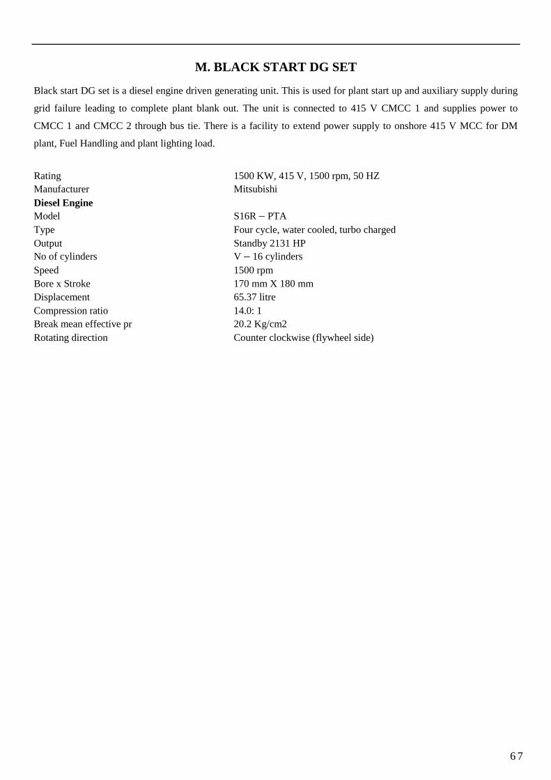
M. BLACK START DG SET
Black start DG set is a diesel engine driven generating unit. This is used for plant start up and auxiliary supply during
grid failure leading to complete plant blank out. The unit is connected to 415 V CMCC 1 and supplies power to
CMCC 1 and CMCC 2 through bus tie. There is a facility to extend power supply to onshore 415 V MCC for DM
plant, Fuel Handling and plant lighting load.
Rating 1500 KW, 415 V, 1500 rpm, 50 HZ
Manufacturer Mitsubishi
Diesel Engine
Model S16R – PTA
Type Four cycle, water cooled, turbo charged
Output Standby 2131 HP
No of cylinders V – 16 cylinders
Speed 1500 rpm
Bore x Stroke 170 mm X 180 mm
Displacement 65.37 litre
Compression ratio 14.0: 1
Break mean effective pr 20.2 Kg/cm2
Rotating direction Counter clockwise (flywheel side)
6 7

N. PLANT CONTROLS AND INSTRUMENTATION
Gas Turbine Control System
GE has provided many gas turbines to many customers with Simplex and Redundant gas turbine control
systems which have been produced by Woodward.
Micro Net plus is the gas turbine control system which was supplied by GE. It is the latest in long line of
electronic control system platform used to perform speed, load and process control for all types of prime
movers. The standard Micro Net I/O modules are available to build up a custom control system for any
type or any size of application.
The Micro Net plus control system is a flexible, state-of-the-art digital control
System designed specifically for prime mover control applications such as:
Gas Turbine control Steam Turbine control Hydro Turbine control Diesel and Gas Engine control
System Features
Micro Net control system consists of Hardware and software parts:
Hardware parts: Chassis and slots Power supply units Motorola CPU5200 Processor HMI ( Human machine Interface)
I/O modules and FTM‟s (Field Termination Modules) Fibre-optic switch RIO – Remote I/O Panel
LIO – Local I/O Panel
Software Parts: GAP – Graphical Application Program Watch windows Coder Application Manager Servlink OPC server Control Assistant
6
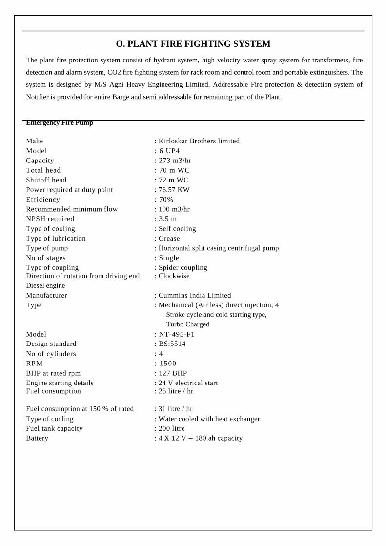
O. PLANT FIRE FIGHTING SYSTEM
The plant fire protection system consist of hydrant system, high velocity water spray system for transformers, fire
detection and alarm system, CO2 fire fighting system for rack room and control room and portable extinguishers. The
system is designed by M/S Agni Heavy Engineering Limited. Addressable Fire protection & detection system of
Notifier is provided for entire Barge and semi addressable for remaining part of the Plant.
Emergency Fire Pump
Make : Kirloskar Brothers limited
Model : 6 UP4
Capacity : 273 m3/hr
Total head : 70 m WC
Shutoff head : 72 m WC
Power required at duty point : 76.57 KW
Efficiency : 70%
Recommended minimum flow : 100 m3/hr
NPSH required : 3.5 m
Type of cooling : Self cooling
Type of lubrication : Grease
Type of pump : Horizontal split casing centrifugal pump
No of stages : Single
Type of coupling : Spider couplingDirection of rotation from driving end : Clockwise
Diesel engine
Manufacturer : Cummins India Limited
Type : Mechanical (Air less) direct injection, 4
Stroke cycle and cold starting type,
Turbo Charged
Model : NT-495-F1
Design standard : BS:5514
No of cylinders : 4
RPM : 1500
BHP at rated rpm : 127 BHP
Engine starting details : 24 V electrical startFuel consumption : 25 litre / hr
Fuel consumption at 150 % of rated : 31 litre / hr
Type of cooling : Water cooled with heat exchanger
Fuel tank capacity : 200 litre
Battery : 4 X 12 V – 180 ah capacity

P. START UP VACUUM SYSTEM
Start-up Vacuum Pump
Manufacturer NASH KOREA
Type Liquid Ring
Quantity 1
Hogging capacity at 10 inch HgA 595 Sm3/hr
Evacuation volume 450 m3
Hogging suction pressure 254 mm HgA
Suction temperature 33 deg.c
BHP 42 KW
No of stage 1
Speed 590 rpm
Hogging time required to reduce suction pr
from atmosphere pr to 254 mm HgA 20 min
Discharge pr Atmospheric
Material of construction –Casing A48
Shaft KSD 3752 SM45C (EQ. A576)
Rotor A536
Pump direction of rotation C.W from driver end
No of bearings 2
Type of bearing Roller
Type of lubrication Grease
Pump-Motor coupling Flexible
Seal water requirement –Flow 7.95 m3/hr
Temperature 35 deg.c
Moisture separator
Dimension O.D 390 mm X 1375 mm H
Material KSD 3503 (EQ. A283)
Silencer
Size O.D 460 mm X 1830 mm H
Type Vertical
Material KSD 3503 (EQ. A283)
Motor
Rating 45 KW
Poles 10 poles
Rotor Type Squirrel Cage
Enclosure Totally enclosed
Cooling method Fan cooled
Frequency 50 HZ
Phase 3
Insulation class F
Temperature rise at full load 90 deg.c
Voltage 415 V
No load current 75 A

Full load current 113 A
Starting current 670 A
Speed 590 rpm
Efficiency –At 1/2 load 85 %
At 3/4 load 87.5 %
At full load 88 %
Power Factor –At 1/2 load 54 %
At 3/4 load 60 %
At full load 63 %
Q. STEAM TURBINE DEAERATING CONDENSER
Heat duty at rated condition 473800000 KJ/hr
Heat duty at HP/LP bypass valve operation 669700000 KJ/hr
Maximum dissolved oxygen content 7 ppb
Condenser pressure 0.077 bara
Condensate temperature 40.8 deg.c
Manufacturer HHI
Quantity 1
Applied design code HEI
Operating life 30 years
Reference condition –Barometric pressure 1.004 bara
Relative Humidity 75 %
Ambient air temp 31 deg.c
Cooling water temp (sea water) 29 deg.c
Maximum makeup water 30 m3/hr
Type Deaerating condenser
Hotwell capacity –From normal level to low level 3 minutes
From normal level to bottom 5 minutes
No of passes 2
Performance at rated condition
LP turbine exhaust –Flow 225619 m3/hr
Enthalpy 2266.7 KJ/Kg
Gland steam condenser drain –Flow 245 Kg/hr
Enthalpy 196.2 KJ/Kg
Steam Jet air ejector drain –Flow 300 Kg.hr
Enthalpy 193.5 KJ/Kg
Condensate leaving condenser –Flow 226164 Kg/hr
Enthalpy 170.8 KJ/Kg
Temperature 40.8 deg.c

Pressure 0.077 bara
Circulating water –Inlet temperature 29 deg.c
Temperature rise 8 deg.c
Inlet pr 2.2 bara
Flow 14565 m3/hr
Specific gravity 1.02
Head Loss 4.5 m
Performance at 100 % bypass
HP bypass –Flow 194040 Kg/hr
Enthalpy 2770.9 KJ/Kg
Temperature 162 deg.c
Pressure 5 bara
LP bypass –Flow 65812 Kg/hr
Enthalpy 2745.3 KJ/Kg
Temperature 143 deg.c
Pressure 3 bara
Condenser neck spray from CEP outlet –Flow 5983 Kg/hr
Enthalpy 191.2 KJ/Kg
Condensate leaving condenser –Flow 266236 Kg/hr
Enthalpy 191.3 KJ/Kg
Temperature 45.7 deg.c
Pressure 0.0993 bara
Cooling water inlet temp 29 deg.c
Cooling water outlet temp 40.3 deg.c
Tubing
Diameter 25.4 mm
Thickness mm (BWG) 0.5 (25), 0.7 (22)
Effective surface area 5137 m2 (5292 m2)
No of tubes 7852 (8088)
- 25 BWG 7952
- 22 BWG 136
Effective length 8200 mm
Tube velocity 2.2 m/s
Cleanliness factor 0.9
Water box velocity (inlet) 1.964 m/s