technical ~e~qra~dum - nasa · technical ~e~qra~dum x-160 , *r: . ... technical memorandum x-160...
TRANSCRIPT

TECHNICAL ~ E ~ Q R A ~ D U M X-160
, *r:
.
https://ntrs.nasa.gov/search.jsp?R=19660024025 2018-06-05T19:53:50+00:00Z

NATIONAL AERONAUTICS AND SPACE ADMINISTRATION
TECHNICAL MEMORANDUM x-160
EFFECTS OF BOUNDARY-LAYER SUCTION AND SPOIIXRS ON
"FANSONIC FLUTTER DERIVA!I!IVES FOR A MIDSFAN
By John A. Wyss, Robert E. Dannenberg, Robert M. Sorenson, and Bruno J. Gambucci
SUMMARY
The e f f ec t s of suction and spoi lers on t ransonic sec t iona l control- surface f l u t t e r der ivat ives were determined i n the Ames 14-foot transonic wind tunnel f o r a midspan f l a p - t y p control surface on a s t r a igh t wing having an aspect r a t i o of 3, a taper r a t i o of 0.6, and a wing-thickness r a t i o of 0.06. the t r a i l i n g edge. each s ide of the control surface for successive locat ions of 77.3-, 86.6-, and 95.7-percent wing chord. sponding t o a height t o midspan wing chord r a t i o of 0.006 and were located on the control at the 82-percent wing chord s t a t ion .
Flap chord extended from the 70-percent chord s t a t i o n t o Suction was applled on spanwise perforated s t r i p s on
The spoi lers were 0.3 inch high, corre-
The appl icat ion of suction during control-surface o s c i l l a t i o n reduced the damping a t subsonic speeds and lowered the Mach number f o r i n s t a b i l i t y . I n cont ras t , the spoi le rs had a s t ab i l i z ing e f f e c t a t subsonic speeds.
INTRODUCTION
Recent s tudies of the single-degree-of -freedom ( r o t a t i o n a l ) f l u t t e r of f lap-type control surfaces have indicated t h a t unless the designer r e so r t s t o the addi t ion of nonaerodynamic damping, t h i s type of f l u t t e r cannot be prevented i n l imited transonic speed ranges except by a change i n the configuration. Examples of such a configuration change, given i n references 1 through 4, include a so l id wedge type control surface with a blunt t r a i l i n g edge, addition of t r iangular wedges ( t e t r&edra ) , use of spoi le rs on the control surface, o r simply reduction of control-surface aspect r a t io . Each of these modifications w a s found t o reduce o r elim- ina te f l u t t e r over ce r t a in speed ranges; however, such changes i n
~~ -
+Title , Unclassified
2 c
4
configuration except f o r the l a t t e r would be expected t o produce undesir- able drag penal t ies (e.g. , r e f . 5 ) .
A means of influencing the flow f i e l d without changing the prof i le , and thus possibly avoiding a drag penalty, i s the use of suction on o r near the control surface. It w a s reasoned t h a t suction would influence the shock wave and the boundary layer and hence would a f f ec t aerodynamic damping of the surface. An exploratory program w a s conducted t o determine the e f fec ts on transonic f l u t t e r derivatives of suction applied on s ingle spanwise s t r i p s on both s ides of a conventional flap-type control surface. The s t r i p s were t e s t ed f o r three successive chordwise s ta t ions . In addition, the e f f e c t of spoi le rs mounted on the control surface w a s inves- t igated. The r e su l t s f o r such a spoi le r configuration on a swept wing are contained i n reference 4.
The control surface t e s t ed w a s a midspan 30-percent p la in f l a p which formed pa r t of a 6-percent-thick unswept wing with an aspect r a t i o of 3. The sect ional f l u t t e r der ivat ives were determined by means of pressure c e l l s a t forced frequencies of the control surface from 10 t o 30 cycles per second f o r a constant amplitude of k1.08'. Mach number varied from 0.6 t o 1.12, with corresponding Reynolds number ranging from 10.4 t o 14.8X10⁶. Angle of a t tack and mean angle of f l a p def lect ion were 0'.
NOTATION
loca l wing semichord, f t
balance chord (dis tance from hinge l i n e t o leading edge of cont ro l ) , f t
control chord (dis tance from hinge l i n e t o t r a i l i n g edge), f t
HM 1 2 2
control hinge-moment coef f ic ien t , p PV C t
, per radian ach - as
PI - P pressure coef f ic ien t , 9
suct ion quantity coef f ic ien t , - Q VSS

K
0 . 0 0. 0.0 0 . . 0 0 ~ 0 ~ 0 0 0 . 0.0 0 0 0 .
0 . 0 0 . 0 0 0 0 . 0 0 0 0 0.0 0 0
0 . 0 0 0 0 0 . 0 0 0 0. 0.0 0 0 0..
3
total -control chord, et, + cf, f t
frequency , cps
hinge moment, foot-pounds per foot of span
reduced frequency, * , with b taken at 3/8 semispan v
r r ee - s t r em Ylch number
l o c a l s t a t i c pressure , l b / f t 2
free-stream s t a t i c pressure , lb/ f t2
free-stream dynamic pressure , l b / f t2
quantity flow r a t e of suction air, f t3/sec
suction reference area, portion of wing area included within f l a p span, f t 2 (see f i g . 4)
veloci ty of air stream, f t / s ec
longitudinal distance i n chord lengths
angle of attack, deg
control-surface deflection angle, radians except where noted
mean angle of control-surface deflection , deg
control-surface angular velocity , - d6 , raiiians/sec
phase angle of resul tant aerodynamic moment with respect t o control-
a t
surface displacement , deg
density of air stream, slugs/ft3
mar frequency , 25rf , raxtians/sec

4 ............... ....... . . . . . . . . . . . . . . . .
c
J
Vector Notation
Unstable o < e < 180
+
180 < e < 360 Stable
L
APPARATUS
The present invest igat ion w a s conducted i n the Ames 14-foot transonic wind tunnel. Descriptions of t h i s tunnel and the apparatus used therein, the control-surf ace drive system, instrumentation, and corrections and precision applicable t o the measurement technique are contained i n refer- ence 2. A sec t iona l sketch of the nozzle and t e s t sect ion i s shown i n f igure 1. Figure 2 chows a view of the model mounted i n the t e s t section. A schematic drawing of the control-surface dr ive system i s shown i n f igure 3.
Model
The model ( f i g . 2 ) w a s mounted on base p la tes bol ted t o the tunnel f l oo r . model i s a wing with an aspect r a t i o of 3, a 6-foot semispan, a taper r a t i o of 0.6, an unsvept ‘(0-percent chord l i ne , and a 30-percent-chord trailing-edge-type flap occupying the middle half of the semispan. The
Model plan-form dimensions are shown i n f igure 4. The basic
a
b
5
wing had an NACA 65~006 prof i le which w a s modified t o a blunt t r a i l i n g .r edge of 0.2-inch thickness. This modification f a c i l i t a t e d pressure-cell
i n s t a l l a t ion at the t r a i l i n g edge. Chordwise rows of pressure c e l l s and pressure o r i f i ce s were ins ta l led a t 3/8 and 5/8 s ta t ions of the semispan. The control surface had a balance-chord t o flap-chord r a t i o of 0.25 based on the mean aerodynamic chord of the f lap. The hinge l i ne was perpendic- u l a r 'GO the wind stream.
Previous experience indicated the necessity f o r additional s t i f fnes s and damping of tne dng. %is was provided by a 5/32-inch a i r c r a f t cable which was passed through the p l a s t i c wing t i p , swq thack about 20 , and attached t o a cantilever spring system outside the tunnel walls (see f i g . 2) . It was found t h a t the control surface could be osc i l la ted safely, with negligible coupling between the control surf ace and wing.
0
Control Surface and Suction System
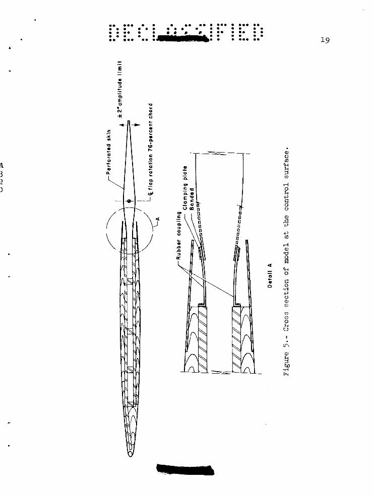
A t yp ica l cross-section drawing of the model i s shown i n f igure 5. The spar of the wing was constructed of s t e e l plates i n order t o provide ducting between the vacuum pumps and the control surface.
The porous skin of the control surface, shown i n f igure 6, consisted - of a perforated aluminum sheet fastened t o r ib s which were spaced approx- imately 6 inches apart . 47 holes (0.094 inch diameter) per square inch in a staggered pattern, which made i t s area 33 percent open. The spanwise porous s t r i p s were obtained by covering the remaining portions of the perforated sheet with a nonporous tape approximately 0.003 inch thick.
The perforated sheet (0.125 inch th ick) had
The chordwise extent of the p r o u s region on the control surface was selected on the bas i s of obtaining a suction pressure in the duct suffi- c ien t ly lower than the surface pressures t o insure an inflow velocity var ia t ion of no more than +lo percent along the span of the f lap . width selected was 0.54 inch. w a s about 100 f e e t per second a t M = 1.0. Three chordwise positions of the center l i ne of the porous region were selected: 77.3-, 86.6-, and 95.7-percent wing chord. The porous s t r i p a t 77.3-percent chord i s i l l u s t r a t e d i n f igure 7(a) . For a basis of comparison the completely taped f l a p was also tes ted.
The The average inflow velocity (both surfaces)
An a i r t i g h t f lex ib le coupling, detai led in f igure 5, joined the control surface duct t o the wing duct over the en t i r e f l a p span. Since the t e s t method involved only pressure measurements obtained during forced osc i l l a t ion of known frequency and amplitude, res t ra ining forces exerted by the coupling had no e f f ec t on the r e su l t s .
.

L
6
A i r w a s drawn through the porous region in to the hollow spar i n the model and then through a ducting system by the vacuum pumps located outside the t e s t chamber. the plenum chamber surrounding the tes t sect ion i n order t o reduce the pressure r a t i o across the pumps. duct system w a s measured by means of a standard A.S.M.E. o r i f i c e .
.'
The exhaust from the pumps w a s discharged in to
The quantity of a i r flowing through the
The control surface w a s a l so equipped with spoi le rs on both s ides located a t 82-percent wing chord ( f i g . 7 (b ) ) . The spoi le r w a s 0.3 inch i n height corresponding t o a height t o chord r a t i o of 0.006 at midspan. For t h i s arrangement, the perforated sections of the f l a p w e r e completely taped.
SCOPE OF TESTS
Sectional f l u t t e r der ivat ives f o r the control surface were obtained f o r the various configurations f o r a wing angle of a t tack of 0' and f o r a mean angle of control-surface def lect ion of 0' f o r a range of Mach numbers from 0.6 t o 1.12. mean aerodynamic wing chord varied from 10.4 t o 14.8 mil l ion. surface w a s o sc i l l a t ed a t an amplitude of k 1 . 0 8 ~ at frequencies from 10 t o 30 cycles per second. With Mach number and wing angle of a t tack constant, data were taken f o r time in te rva ls of about 30 seconds at each frequency. The over-al l accuracy of the pressure-cel l da ta i s estimated t o be 5 percent i n magnitude and +3O i n phase angle.
The corresponding Reynolds numbers based on The control
(See r e f . 2. )
RESULTS AND DISCUSSION
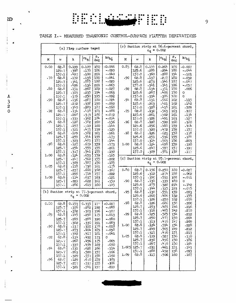
The sec t iona l f l u t t e r der ivat ives a re presented i n t ab le I ( a ) f o r the completely taped control surface, tables I ( b ) through I ( d ) f o r the suction- s t r i p configurations, and in tab le I ( e ) f o r the spo i l e r data . pressure d is t r ibu t ions are tabulated i n t ab le 11.
S t a t i c
A l l data presented were derived from the lower row of pressure c e l l s located a t the 3/8-semispan wing s t a t ion . investigation are i n the form of high-speed motion-picture shadowgraphs.
Supplemental r e s u l t s of the
One important feature of transonic control-surface f l u t t e r i s t h a t the flow f i e l d charac te r i s t ics are not appreciably d i f f e ren t as frequency i s increased from low t o moderate frequencies, say from 1 t o 60 cycles per second- investigations reported in references 2, 3 , and 6 indicate shock-wave pat terns which show only minor var ia t ions as frequency i s increased. One might assume tha t the magnitude of the der iva t ive i s dependent on how far the shock wave moves, while phase angle i s dependent on the pressure f i e l d
For example, study of shadowgraph motion pictures from . I
.
1
an’ boundary-layer conditions which not only have an e f f e c t on Ease lag but are undoubtedly important i n determining shock-wave excursion. should be pointed out t h a t interference e f fec ts such as would r e s u l t from an adjacent surface are excluded from these remarks.) Boundary-layer control of fe rs the poss ib i l i t y of changing flow f i e l d character is t ics without changing the external contour of a par t icu lar configuration, with possible benef ic ia l e f f ec t s on the f l u t t e r problem.
(It
The effects of suction and spoi le r addition on the static-pressure dis.i;r;>-.+’nn UVAvr- nf the coxtrol-surface model are shown i n f igure 8. The application of suction accentuates tke x g n t i v e pressure peak at about 30-percent chord while the spoi le r increases the pressure doe& of the spoi lers . Large discont inui t ies i n pressure coeff ic ient are produced by each configuration i n the region of the control surface.
The e f fec ts of suction and spoilers on the f l u t t e r derivatives are described i n r e l a t ion t o f igure 9. of suction, cq = O.OOl9, had a re la t ive ly s m a l l e f f ec t on the magnitude and phase angle of hinge-moment derivative ( f i g . 9 (a) ) and on the aero- dynamic damping component ( f ig . 9(b)) . reduce damping a t subsonic speeds and lower the Mach nuniber f o r i n s t ab i l i t y . Curves are shown only f o r me s t r i p location, 86.6 percent. other locations of the suction s t r i p were qui te similar and differed only i n secondary de ta i l .
It may be noted tha t the application
Suction appeared actual ly t o
Results f o r
In contrast t o the resu l t s obtained with suction, the spoi ler had a pronounced s tab i l iz ing e f fec t . Although the magnitude of the derivative lChgl w a s almost constant with Mach number, phase angle, 8 , had a pro-
nounced s h i f t toward the s tab le condition ( f ig . 9 (a ) ) . This resul ted i n the more s tab le subsonic damping components shown i n f igure 9(b). be noted, however, t h a t the s h i f t i n phase angle was not suf f ic ien t t o maintain s t a b i l i t y a t supersonic speeds. This r e su l t is d i f fe ren t from those f o r a swept wing reported in reference 4, i n t h a t similar spoi le rs were e f fec t ive i n maintaining s t a b i l i t y i n the supersonic speed range. However, the present control configuration w a s d i f fe ren t i n t h a t it had aerodynamic balance whereas the control i n reference 4 had mass balance but no aerodynamic balance.
It may
Examination of the shadowgraph picture disclosed tha t the application of suction was ineffect ive in a l ter ing the shock-wave posit ion o r motion during osc i l la t ion . However, small disturbance waves d id occur along the suction s t r i p . No evidence of pronounced separation could be detected from s t a t i c pressures so t h a t the removal of a large separated region did not const i tute the primary function of suction. It thus seems l ike ly t h a t an extremely large increase i n suction capacity would be required t o a l t e r the r e su l t s appreciably.
The e f fec t of the spoi ler was s t r i k ing i n t h a t motion of the shock wave along the surface during control-surface osc i l la t ion w a s almost

8
E
completely eliminated. angular shaped wedges reported i n reference 3 i n which shock-wave motion decreased coincident with the delay of i n s t a b i l i t y t o a higher Mach number.
This e f f ec t i s qui te s imi la r t o t h a t f o r tri-
m
Reynolds Number
A brief investigation of the e f f ec t s of Reynolds number w a s conducted i n the Ames Unitary Plan wind. tunnel. Reducing Reynolds number by a factor of 3 resul ted i n only s m a l l changes i n the trends and magnitudes of the data f o r the p la in control surface. those i n reference 4 i n which the e f f ec t s of Reynolds number f o r a swept- wing control-surface configuration were found t o be s m a l l .
These r e su l t s are similar t o
Ames Research Center National Aeronautics and Space Administration
Moffett Field, Cal i f . , Oct. 7, 1959
EGFEFLENCES
1. Moseley, W i l l i a m C . , Jr., and Thompson, Robert F.: Effect of Control Trailing-Edge Thickness o r Aspect Ratio on the Osci l la t ing Hinge- Moment and F l u t t e r Characterist ics of a Flap-Type Control a t Tran- sonic Speeds. NACA RM L58B25, 1958.
2. Wyss, John A., Sorenson, Robert M., and Gambucci, Bruno J . : Effects of Modifications t o a Control Surface on a 6-Percent-Thick Unswept Wing on the Transonic Control-Surface F l u t t e r Derivatives. NACA RM ~ 5 8 ~ 0 4 , 1958.
3. Wyss, John A., Sorenson, Robert M. , and Gambucci, Bruno J.: Measure- ments of Transonic F l u t t e r Derivatives f o r a Midspan Control Surface on a Modified Delta Wing. NASA TM X-157, 1959.
4. Herr, Robert W . , Gibson, Frederick W . , and Osborne, Robert S. : Some Effects of Flow Spoilers and of Aerodynamic Balance on the Oscil- l a t ing Hinge Moments f o r a Swept Fin-Rudder Combination i n a Tran - sonic Wind Tunnel. NACA RM ~ 5 8 ~ 2 8 , 1958.
5- Gambucci, Bruno J., and Wyss, John A. : Ex,-rimental Investigation of the Drag Due t o Wedges Along the Trai l ing Edge of a Swept Wing. NACA RM ~ 5 8 ~ 1 3 , 1958.
Analyzing f o r Transonic F l u t t e r of Control Surfaces Based on Avail- able Experimental Evidence.
6. Erickson, Albert L., and Stephenson, Jack D. : A Suggested Method of
NACA RM A7F30, 194?(. -
0.156 .312 -390 -138 -275 -344 -130 .260 .326 .126 -253 .316 -325 .250 .313 .I24 .249 .3U
.238 -297 .231 .288 .ll5
-119
0.250 .2’(4 -531 -339 .328 *315 -551 .486 .250 .686
.485 -585
.594
e485
-437 .476
-505 .476
A56 -476 .461
.506
-527
.452
0.80
.85
62.8 0.153 0.335 177 125.7 .306 .282 192
62.8 .145 .298 T 175 157.1 .382 .303 196
.289 I .288
.362 .330
.273 .4&
.342 .k17 -134 .412 .268 .456 .335 .454 .131 .628
-329 -557 .m .670
.321 .541
-137 -351
-263 *520
,257 -537
190 191
185 181 173 175 169 166
158 159
157
178
157
3-55
0. 0.0 0 0 0 0. 0. 0 0 0 0 0 0.0 0 0 0 . 0 0 0 0 0 0 0 0 0 0 0 0 0 .
0 . 0 0 0 0 0 0 0 0. 0 0 0 0 0 0 0 0 0 0 0 0 0 0 0.0 0 . 0 0 0 9
TABU I. - MEASUFUD TRANSONIC CONTROL-SURFACE FLllTITR DERIVATNES ~~ ~ ~~ ~ ~~ ~~
(c) Suction strip at 86.6-percent chord, cq = 0.002 (a) Flap surface taped
- M -
W - 62.8 125.7 157 - 1 62.8 125.7 157.1 62.8 125.7 157.1 62.8 125.7 157.1 62.8 125.7 157.1 62.8 125.7 157.1 62.8 125.7 157-1 62.8 125.7 157-1 62.8 125-7 157.1 62.8 125.7 157.1 62.8 125.7 157.1 -
- k
3.19 -398 - 497 .l?O
-
. j L t i
.426 - 1-51 - 303 -379 .136 - 272 .340 .134 -268 -335 .128 -257 .321 - 3-29 - 259 - 323 -3-27 -254 - 317 .I24 .247 -309 .u8 -237 - 296 .ll4 -229 .286 -
- 1% I - 0.109 .170 .loo * 135 .C?Ec? .136 .268
.287 - 308 -289 .418 * 373 -362 - 582 519 ,473 .582 .544 .485 * 679 -555 -91 -653 .560 * 587 -730 .660 .716
-622 .619
* 235 250
-637
-
- M
- k - 3.144 .288 .360 -137 -273
-134 * 341
.267 -334 .131 .263 .328 .13c .261 .326 .I26 .256 .320 .126 .251 .314 .124 .247 -309
- e, de !3
18 0 188 194 180 187 186 Lee 180 180 162 162 161 163 161 163 160 159 159 158 155 156 159 157 158
-
-
kCh . 6
.o .007 -.ow+ - .lo1 - .032 -.&7 -.m7 .006
0 0 -115 .142 - 109 .lo7 .134 .127 .180 .164 - 157 -178 -188 * 203 .190 -197 * 177
w - 62.8
62.8 125.6 157.0 62.8 125.6
62.8
62.8 125.6 157.0 62.8 125.6
62.8
62.8
125.6 157.0
157.0
125.6 157.0
157.0
125.6 157-0
125.6 157.0
0.60
.70
.80
* 90
* 92
.94
* 96
-98
1.00
I.. 05
1-09
-
180 186 201 180 188 201 182 194 195 180 190 18 7 181 186 184 160 160 159 163 155 15 7 159 155 155 159 155 156 161 160 157 163 161 160 -
-0.066 -.020 -.&O -.&l -.w5 -.a52 -.M7 -.063 -.092 -.024 -.092 -.068 -.&I8 - * 072 -.m4 .156 .144 - 125 .161 -173 .144 e173 .201 .190 .165 .202 -185 .178 * 167 .222 -121 - 159 .I45
0.85
- 90 -92
-94
-95
- 96 -98
1.00
A
2 0
i3
. ~
( d ) Suction strip at 95.7-percent chord,
-0.027 -.&2 -. 071 0 - -142 -so75 -093 - 155 .076 .200 .216 .270 .212 .2& 209 .228 .2l2 .213 .170 .186 .1& .143 * 093 -167
0.80
-90
- 95 * 98
-99
1.00
I.. 05
1.03:
1. og
62.8 125.6
62.8 125.6
62.8 125.6 157-1 62.8 125-7 157.1 62.8 125.7 157.1 62.8 125.7 157.1 62.8 125-7 157.1 125.7 157.1 62.8
157 * 1
157.1- (b) Suction strip at 77.3-percent chord,
c = 0.002 9 ~~
-0.007 -.&I8 - .io7 - .013 -.@O -.@3 - .018 -.@8 -.&l 0 - 005 .050 .114 .166 .160 .183 .186 - 219
157.1
157.1
157.1
157-1
157.1

I 10
0 . ... . 0.. . 0 . 0 . . . . 0.. 0 . 0 . 0 . .. 0 . 0 0 . . 0 . .
0 . 0.. . . ... 0 . 0.. .. 0 . 0 . 0 . . 0 . 0:- 0 . . 0 .... ... ,
I
1
TABLE I. - MEASURED TRANSONIC CONTROL-SURFACE FLUTTER DERIVATIVES - Concluded .
~~ r- ~~ ( e ) Spoiler at 82-percent chord
M
0.80
.85
-90
92
*94
* 96
-98
1.00
1.05
1.10
u
62.8 125 - 7 157.1 62.8
125.7 157.1 62.8
125.7 157.1 62.8
125.7 157.1 62.8
125 * 7 157.1 62.8
125 7 15-70 1 62.8
125.7 157.1 62.8
125 - 7 157.1 62.8
125* 7 157.1 62.8
1250 7 157- 1
k
9.155 .310 387
.290 0363 137
.274
.342
.134
,145
.267 334
.131
.262
.128
.256
.320
0327
125 .251 .314
.247 123
.308
.118
.236 0295 .113 227
.283
l%l 9.313
324 .341 .289 .266 377 302
.256 303 253
.274 294
.272
.310
.287
-336 312
-317 .402 ,303 .306 ,438 .322 327 ' 493 .381
-275
.304
.314
352
- 0 , l e g
186 199 180 188 208 215 1-9 7 226 18 0 196 227 219 202 2 12 207 201 195 19 7 182 171 175 166 159 161 161 162 163 162 163 162
- kchf,
-0.074 - -065 -. 153 -. 084 - - 097 -. 1 5 i - .060 - .114
-. 091 -. 131 - .149 -. 087 -. 121 - .116 -.lo8 -. 078 -.@6 -0075
. o n
.005
.066 ,078 .068 .096 .066 .064 .loo * 075
- a 158
.072
.

c
a
A 3 2 0
TABLE 11.- MEASURED PRESSURE DISTRIBUTION FOR THEC SEMISPAN PAN SE~ION; 6 = o
3ord- W l a c
; t a t ion, Frcent chord
~-
5 15 25 37.5 45 55 62.5 67.5 70.6 71.9 74.6 80.1 85.4 89.2 9390 95-9
5 15 25 37.5 45 55 62.5 67.5 70.6 71.9 74.6 80.1 85.4 89.2 93.0 95.9
1 (a ) Flap surface taped
Mach number
Pressure coeff ic ient , cp
0.073 -. 196 - .206 - .211 -.231 - .278 - 0 155 - .176 -.la - .185 -.021 0 - .016 .I84 .086 122
~
0- 075 - .191 -.2&
- . ~ 6 - .300 -.204 - .178 -.292 -029
0 - .010 - 175 .088 - 125
- e 2 5 0
--227
0.120 - 152 - .178 - .138 - .211 - .150 -.2I2 - 219 - 173 -.191 .060 057 -033 - .143 .132 .172
0.105 - .169 -. 196 - .260
- .346 -. 196 -.3& - .322 -. 150 -0og ..ow -9175 105 .148
- .243
- 234
0.126 - .150 - 193 - .248 - 229 - 349
-0376 - 378 - .266 -.dl - .017 - 179
.loo
.138
- 229 -.202
0.153 - .113 - .171 - 234 - .214 -0338 - 9 355 -303 - .415 - .415 - 0 325 -9235 - .066 - e 2 1 5 077
.124
(b) Spoiler located a t 81.8-percent span
0.073 -. 191 - .201 - .211 - .216 - .221 0082 .082 -0052 - .064 -237
- .480 - 382 - 062 .018
- 125
0.083 - .190 -.204 -.248 - .229 - 287 -0092 -0092
.005 - ,013 .131 238
- .063 .013
- .496 - .401
-
0- 095 - -182 - 205 - .260 -.2# - 285 - .181 -.I24 - .030 -.&1 .I46 .243 - 505 - .&lo -. 051 .026
0.110 - .169 - 196 - 285 - .262 - 245 -0393 - .187 -.&7 - .056
.070
.2l2 - 473 - 383 -.w8 .044
0- 133 - .147 - .190 - .246 - .234 - 351 - 298 - .162 - .166 - .067 .lo1
- .388 - 395 - .023 .050
- 272
0.154 - .113
- -216 - 356
- 176 -9235
- .g42 -0325 -a217 - 219 - - 165 .018
- .361 -e397 -.051 0027
0.215 - . op -.122 - 185 - 165 -e293 - .321 - 357 - - 425 - 427 - .288 -0295 - 313 - 460 - .128
-00g - 0.200 -.069 - .138 -0193 - .174 -.304 - 334 - 365 - 341 - 341 - .244 --w - .443 - 495 - .182 -.082
11 1

12
TABU 11. - MEASURED PRFSSURE DISTRIBUTION FOR THE 5/8-SEMISPAN SECTION; 6 = 0 - Continued
( c ) Suction s t r i p at 77.3-prcent span, cq = 0.002
Chord- w i s e
s tat ion, percent chord
5 15 25 37.5 45 55 62.5 67.5 70.6 71.9 74.6 00.1 85.4 89.2 93.0 95.9
Mach number
0-90 I 0.92 I 0.94 I 0.96 I 0.98 I 1.00
0.080 -0199 - .209 -. 266 -. 236 - ,298 -. 262 - 239 -. 216 - 234 - .010
.067
.047
.041 -089 .149
Pressure coeff ic ient , cp
0.096 - .191 - 224 - 285 --253 - 299 - .262 -. 274 - 254 - .283 -. 011
.096
.052
.038
. lo4
.158
0.115 - - 171 - 196 -0259 -*237 -0325 - 190 - .229 -. 380 - 395 - 233
-087 .068 .068 .112 .168
0.137 - 146 -. 185 - .249 -. 227 -9333 - .202 - a 205 -.408 -. 408 -. 322 -. 071
.io7
.160
.022 019
( d ) Suction s t r i p a t 86.6-percent span, cq = 0.002
5 15 25 37.5 45 55 62.5 67-5 70.6 71.9 74.6 80.1 85.4 89.2 93.0 95.9
0.078 - .198 - .208 - .266 - 234 - ,300 - * 256 - 234 -. 181 - .198
023 - .044 -. 063
* 073 . io6 * 150
0.096
- .218 - .283
-a195
- 254 - 285 - 258 - 274 - ,224 - 246
.019 -. 020 -9053
em5 .117 .164
0.124 -. 167 - 193 -.e76 -0257 -0353 -. 267 - 276 -0343 - - 356
- .067 -. 062
.086 - 133 172
- e 194
0.131
- . io6 -. 262 - .240 - 355 - - 224 -. 210 -. 382 -0379 - * 290 -. 151 - - 115
- e 154
.070
.131
.169
-
0.063 -. 171 -0275 -. 340 - * 313 -. 340 - .405 - 343 -. 414
- .414 - ,400 -. 324 -. 076 .010 ,056
-*515
0.192 -.058 - .I46 -. 226 -. 211 -. 184 -. 310 - - 336 -. 415 - .417 -. 300 -a313 -. 318 - .060
.088
.143
c

. . *
1 0.218 -.&3 - .lo4 - .174 - .I48 - .304 - .414 - .417
-0277
- - 343 - -278 -. 310 - .286 - 273 - - 251 -. 194
L
i
. TABLE 11. - MEAS= PFC3SSU€E DISTRIBUTION FOR THE 5/8-SEMISPAN SECTION; 6 = 0 - Concluded
(e) Suction strip at 95.7-percent span, I Chord-
w i s e stat ion, percent chord
5 15 25 37.5 45 55 62.5 67.5 70.6 71-9 74.6 80.1 85.4 89.2 93.0 95.9
mJ Mach number
Pressure coefficient, cp I 3 077 - .200 -0209 -0259 -. 229 -.a8 - .238 - .219 - 179 - 199 .023
- .011 - .005 .010 -093 157
0.120 -.la - 205 -. 271 - .251 - 349 - .192 -e226
-.348 - .206 - 059 -.OW .014 .056 .162
- .341
0.158 -.I20 -. 184 - .248 - .220 -0347 - 350 - - 285 - .340 - 349 - 256 - 0 227 -- 073 - - 039 - - 037 - 157
3.180 -e093 - .166 - .230 -. 33'c - -358 - .388 -. 430 -0433 - .324 -. 316 - .298 - 0 153
.081
- 207
-. 072

. I . o r
0 . 0.0 . . . 0. 0 . . e.. . 0.0 0. ~~
0 . . 0 . . 0 . 0 0 . 0 . 0 . 0 . 0 . . 0 . 0.. . 0.. 0 .
;* : :* : :
f rl
a, ri N N 0 G
ri cd d 0
I
ri

16
A-24146
Figure 2.- Rear view of model mounted in test section.

. -.-Y
.-a . . e. e. . e.. . e.. e.
Figure 3 . - Schematic drawing of the control-surf ace drive system.

18 0 . 0.. . 0.. . 0 . 0 . . . . 0.. L. ~ ~ . . _.
0 . 0 . . 0 . . 0 . . . . 0 . . 0 . . . .... 0 . 0 . . . . 0 . .
0 . .a. . . . 0 . 0 . . . 0.. 0 . 0.. 0 .
Dimensions in inches
re
Figure 4.- Dimensional sketch of model plan form.
. e. .a. a a a a. *a e aaa a .a. ea . a a a a a a a a a a. a . a .
a a. a ea a e _ . ~ ..a. e ..e a. .a. -a. !*: : : :a* :ae
L - +n- w 0 a= 0
c a 0
a I
L
c
%
n W yc c 0
0
.- c
c
2 n
ul
0 - .c
rl 0 k -tJ E: 0 V
e, 5 -9 Ld rl e,
3 &I 0 r: 0 d -tJ 0 e, m (D m 0 k V
I
L n
5 hD
.rl kl

20
............... ....... . . . . . . . . . . . . . . . . . . . . . . . . . . . . . . . . . . ....... . 0 . 0.. 0 . 0 . 0 . .
L
Figure 6. - Control surf ace. - A-24031.1
1

e

22
( a ) Suction strip a t 77.3-percent chord station, cq =.0019.
-.4
a 0
c Q,
V
- -.2 +
.- G O .c Q, 0 V
.2 ? 3 v) v)
( b ) Completely taped.
0 20 40 60 80 100
(c ) Spoilers at 82-percent chord stat ion. Wing station, x
Figure 8 . - Wing and control-surface static pressure coefficients, M = 0.90.

24
--4
7 3
-. 2
- _ I
k c h i 0
.I
.2
-3
.4
.. 0.. . 0.0 . . . 0.0 0.
0 . 0 8 0 . . .... 0 . 0 . 0 . 0 . . 0 . 0
0. 0.. . . . 0. 0. 0 0.. 0. 0.. 0.
0 . 0 0 . .
Suction a t 86.6-percent chord C o m p l e t e l y taped I -- S p o i l e r s a t 82-percent chord
----
=IT S t a b l e ___
tc U n s t a b l e -
.6 .? .8 -9 I .o Mach number, M
--
( b ) Aerodynamic damping component as a function cf Mach number.
Figure 9.- Concluded.
.
.
NASA - Landey Field, Va. A-320

I.- '#: .6
0 -
.. .. 0 a 0 0 b o .. .. .. . . . a** .. .... .
0 . . 23
Suction a t 8 6.6-perc ent chord Co mp I e t ely t a pea --_ -
-- S p o i l e r s a t 82-percent chord
200 S t a b l e
I80
8
160
140 .6 .7 .8 .9 I .O 1 . 1
Mach number, M
( a ) Resultant aerodynamic hinge moment and phase angle as functions of Mach number.
Figure 9.- Results f o r suction, taped, and spo i l e r configurations; k = 0 . 3 , c = 0.0019. cl