technical filter brochure · 2019-11-23 · technical filter brochure | 7 new part significant...
TRANSCRIPT

Technical filter brochure

2 | Technical filter brochure
3rd edition 10/2014 (062017)Item no. 50 003 596-02
Edited by:Motorservice, Technical Market Support
Layout and production:Motorservice, MarketingDIE NECKARPRINZEN GmbH, Heilbronn
This document must not be reprinted, duplicated or translated in full or in part without our prior written consent or without reference to the source of the mate-rial.
All content including pictures and diagrams is subject to alteration. No liability accepted.
Published by:© MS Motorservice International GmbH
LiabilityAll information in this brochure has been carefully researched and compiled. Nevertheless, it is possible that errors have occurred, information has been translated incorrectly, information is missing or the details provided have changed in the intervening time. As a result, we are unable to provide any guarantee nor to accept any legal liability for the accuracy, completeness, currency or quality of the information provided. We hereby waive all liability for any damages, whether direct or indirect in nature and whether tangible or intangible, resulting from the use or misuse of information or from incomplete or incorrect information in this brochure, unless proven to be the result of deliberate intent or negligence on our part.
Likewise, we shall not be liable for damage arising because the engine reconditioner or mechanic does not have the necessary technical expertise, the required knowledge of, or experience in repairs.
The extent to which the technical methods and repair information described here will apply to future engine generations cannot be predicted and must be verified in individual cases by the engineer servicing an engine or the workshop operator.
Motorservice GroupQuality and service from a single sourceThe Motorservice Group is the sales organisation for the worldwide aftermarket activities of Rheinmetall Automotive. It is a leading supplier of engine components for the independent aftermarket. With the premium brands Kolbenschmidt, Pierburg, TRW Engine Components and the BF brand, Motorservice offers its customers a wide and comprehensive range of top quality products from a single source. As a problem solver for trade and repair shops, the corporation also offers an extensive service package. Motorservice customers benefit from the combined technical know-how of a large international automotive supplier.
Rheinmetall AutomotiveRenowned supplier to the international automotive industryRheinmetall Automotive is the mobility division of the technology corporation Rheinmetall Group. With its premium brands Kolbenschmidt, Pierburg and Motorservice, Rheinmetall Automotive is a global leader in the relevant markets for air supply systems, emission con-trol and pumps and in the development, manufacture and spare-parts supply of pistons, engine blocks and plain bearings. Low pollutant emissions, good fuel economy, reliability, quality and safety are the main driving forces behind the innovations of Rheinmetall Automotive.

Technical filter brochure | 3
Contents
Contents Page1 | Introduction 42 | Filtration 93 | Dirt load and differential pressure 114 | The filter medium 135 | Air filters 156 | Cabin filters 207 | Air dryers for brake systems 288 | Fuel filters 299 | Urea filters 3610 | Coolant filters 3611 | Oil filters 3712 | Gear oil filters 4513 | Concluding remarks 45
Glossary 46
4 | Technical filter brochure
1 | Introduction
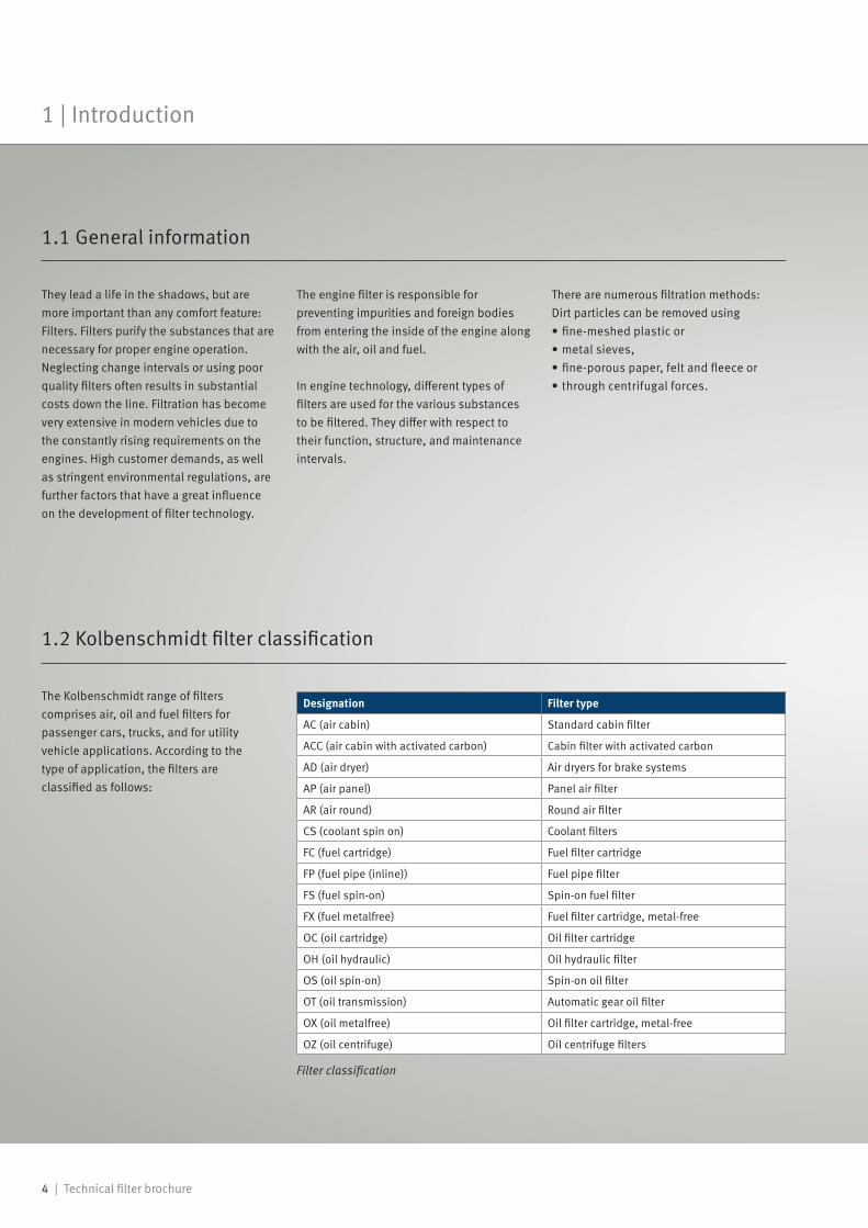
The Kolbenschmidt range of filters comprises air, oil and fuel filters for passenger cars, trucks, and for utility vehicle applications. According to the type of application, the filters are classified as follows:
Designation Filter type
AC (air cabin) Standard cabin filter
ACC (air cabin with activated carbon) Cabin filter with activated carbon
AD (air dryer) Air dryers for brake systems
AP (air panel) Panel air filter
AR (air round) Round air filter
CS (coolant spin on) Coolant filters
FC (fuel cartridge) Fuel filter cartridge
FP (fuel pipe (inline)) Fuel pipe filter
FS (fuel spin-on) Spin-on fuel filter
FX (fuel metalfree) Fuel filter cartridge, metal-free
OC (oil cartridge) Oil filter cartridge
OH (oil hydraulic) Oil hydraulic filter
OS (oil spin-on) Spin-on oil filter
OT (oil transmission) Automatic gear oil filter
OX (oil metalfree) Oil filter cartridge, metal-free
OZ (oil centrifuge) Oil centrifuge filters
1.2 Kolbenschmidt filter classification
1.1 General information
They lead a life in the shadows, but are more important than any comfort feature: Filters. Filters purify the substances that are necessary for proper engine operation. Neglecting change intervals or using poor quality filters often results in substantial costs down the line. Filtration has become very extensive in modern vehicles due to the constantly rising requirements on the engines. High customer demands, as well as stringent environmental regulations, are further factors that have a great influence on the development of filter technology.
The engine filter is responsible for preventing impurities and foreign bodies from entering the inside of the engine along with the air, oil and fuel.
In engine technology, different types of filters are used for the various substances to be filtered. They differ with respect to their function, structure, and maintenance intervals.
There are numerous filtration methods: Dirt particles can be removed using• fine-meshed plastic or • metal sieves,• fine-porous paper, felt and fleece or • through centrifugal forces.
Filter classification

Technical filter brochure | 5
Introduction | 1
Kolbenschmidt uses two number groups for filters: In addition to the standard eight-digit Kolbenschmidt number, there is also a short number. This consists of three or four digits plus two or three letters. The digits identify the filter, the letters explain the filter type (see 2.). The eight-digit Kolbenschmidt number appears in all documents, such as delivery notes and invoices, for example. The first five digits are always "50 013" or "50 014"; the last three or four identify the filter and are the same as the digits of the short number.
Examples:• Oil filter cartridge 095-OC = 50 013 095
• Cabin filter with activated carbon 4027-ACC = 50 014 027
1.3 Explanations of Kolbenschmidt item numbers
Air filters

6 | Technical filter brochure
Whenever moving parts come into contact or mesh, they cause friction which must be avoided.
As a suitable lubricant, mineral or synthetic oil is used which forms a sliding film between the moving machine parts. This ultra-thin separation film acts as a buffer to prevent a direct contact and to allow the parts to slide. This lubrication can only be carried out effectively if the oil remains clean. Even impurities of microscopic size may not be carried because, as abrasive particles, they significantly accelerate the abrasive wear on the engine parts.
Critical points within the engine are the running surfaces of the cylinder liners, pistons, piston rings, valves, gaskets, crankshafts and connecting rod bearings. Foreign bodies can enter the engine directly in the form of sand or sand particles with the fuel or the intake air. Foreign bodies in the system can also indirectly promote wear and cause problems during operation – in the form of fine metal abrasives, residues of incomplete combustion or small fibres, plastic or rubber particles.
1.4 The wear in the combustion engine
1 | Introduction
Engine sectional view

Technical filter brochure | 7
New part
Significant scoring on the main bearing caused by an abrasive mass of oil and dirt particles. Result: Engine damage
Damaged part
1.5 Wear on engine components due to impurities in the system
Piston with clear wear marks: Significant abrasion on the piston
skirt coating. The lack of sliding film may lead to piston malfunction or even piston seizure.
New part Damaged part
Significant wear on the sliding lands of the oil control ring. Result: Increased oil consumption
New part Damaged part
Introduction | 1

8 | Technical filter brochure
1 | Introduction
Significant wear in the area of the 1st ring groove (Fig. 2): The elevated clearance (Fig. 2) leads to reduced compression, resulting in performance losses.
New cylinder liner (Fig. 3) with clearly visible cross-hatching: This surface, produced using a honing tool, improves the oil adhesion on the inner wall of the cylinder.
Cylinder liner with scoring on the inner wall (Fig. 4). The honed surface can no longer be detected. Result: Increased oil consumption
Fig. 1 Fig. 2
Fig. 3 Fig. 4

Technical filter brochure | 9
Filtration | 2
2.2 Filtration effects
A variety of different methods are used to separate dirt particles. These effects will be explained in the following chapters: They mainly depend on the size of the particle to be separated, as well as on the properties of the liquid or gas containing them. Physical effects, such as centrifugal or electrostatic forces, also play a major role in the separation process.
In the following figures, the filter medium is represented as an individual fibre perpendicular to the plane of the figure. Air, oil and fuel move in a laminar flow around the fibre and are shown by simple path curves (streamlines). The blocking effect is the most important separation mechanism in the filtration of oil and fuel. In air filtration, the inertia and diffusion
effects also play a part in addition to the barrier effect.
2.3 Inertia effect
1 Direction of flow2 Stream lines3 Individual fibre: Axis perpendicular to the plane of the figure4 Dirt particles
The inertia effect is based on the fact that dirt particles with a larger mass approaching the fibre leave their streamline path as a result of inertia and directly collide with the fibre.
When talking of filtration in modern vehicles, the main focus lies on depth filters. These special filter elements are used if particles are to be removed from liquids (oil and fuel) or gases (air) to 100 % where possible. The separation of particles is carried out in the depth structure of the
2.1 Basic information
medium on the surface of the individual fibres.
These impurities can be dust, metal abrasion or soot particulates from incomplete combustion. In addition to the solid particles, filters also have to remove
water residues in the fuel lines, as well as oil drops resulting from the blow-by-gas of the crankcase ventilation.
Inertia effect
10 | Technical filter brochure
2 | Filtration
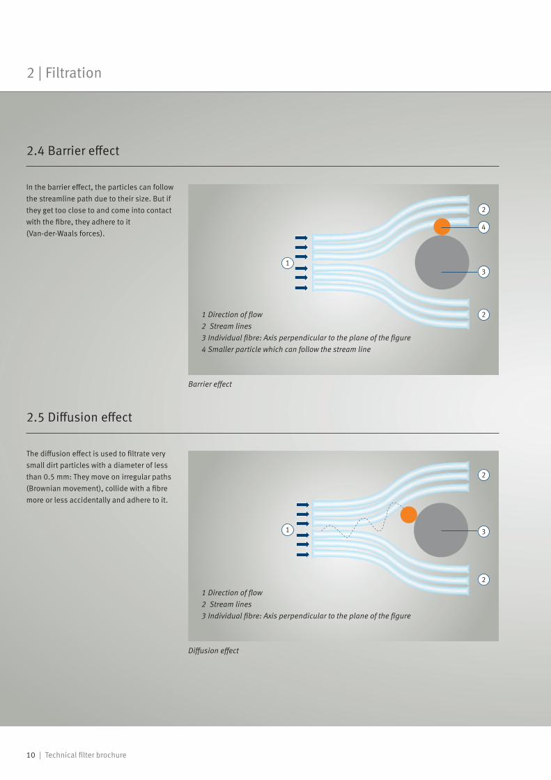
In the barrier effect, the particles can follow the streamline path due to their size. But if they get too close to and come into contact with the fibre, they adhere to it (Van-der-Waals forces).
The diffusion effect is used to filtrate very small dirt particles with a diameter of less than 0.5 mm: They move on irregular paths (Brownian movement), collide with a fibre more or less accidentally and adhere to it.
1 Direction of flow2 Stream lines3 Individual fibre: Axis perpendicular to the plane of the figure4 Smaller particle which can follow the stream line
2.4 Barrier effect
2.5 Diffusion effect
1 Direction of flow2 Stream lines3 Individual fibre: Axis perpendicular to the plane of the figure
Barrier effect
Diffusion effect

Technical filter brochure | 11
Dirt load and differential pressure | 3
The course of the pressure difference Δp over the operating time or dirt load is shown in the diagram: The rather slow increase in the pressure difference is a typical phenomenon with depth filters. Only when the pore volume of the filter is nearly exhausted does the pressure difference rapidly increase. This is when the filter should be replaced. The time t1 is defined in the specification of the car manufacturer.
3.2 Pressure difference over time
1 Latest time for filter replacementMax. differential pressure Δp
Time interval or dirt load
Pres
sure
diff
eren
ce Δ
p
t1
When using a new filter, dirt particles first settle on the fibre surface. With increasing soiling, the thickness of this dirt layer increases and causes a decrease in the
pore volume of the filter. But as the pore volume decreases with the flow remaining constant, the pressure difference rises.
3.1 Basic information
Pressure difference

1 2 5 3 4 6 8
12 | Technical filter brochure
3 | Dirt load and differential pressure
Filters usually have to collect microscopic particulates. The following figure illustrates the different sizes of typical dirt particles which a filter has to collect.
In order to illustrate the dimensions of filtered particles even better, dirt particles and pollens are shown in comparison with the cross-section of a human hair.
1 Human hair (~70 µm)
2 Minimum the human eye can see (~40 µm)
3 White blood cells (~25 µm)
4 Pollen (~10 µm)
5 Dirt particles
6 Red blood cells (~7 µm)
7 Bacteria (~2 µm)
3.4 Proportions
3.3 Dimensions of various particles
Smoke Road dust
Fog Pollen
Spores
Exhaust gases
Soot
Bacteria
0.01 µm 0.1 µm 1 µm 10 µm 100 µmDimensions of various particles
Sizes of dirt particles
Proportions dirt particles
Technical filter brochure | 13
The filter medium | 4
• A high pulsation stability at any dynamic load
• Insensitivity to water (e.g. in case of heavy rain or spray), engine oils, crankcase gases and fuel vapours
• High thermal stability, as temperatures up to 80 °C are possible on the filter element during vehicle operation
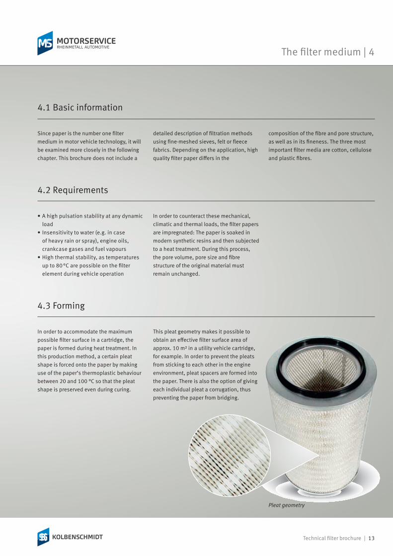
In order to accommodate the maximum possible filter surface in a cartridge, the paper is formed during heat treatment. In this production method, a certain pleat shape is forced onto the paper by making use of the paper‘s thermoplastic behaviour between 20 and 100 °C so that the pleat shape is preserved even during curing.
Pleat geometry
4.2 Requirements
In order to counteract these mechanical, climatic and thermal loads, the filter papers are impregnated: The paper is soaked in modern synthetic resins and then subjected to a heat treatment. During this process, the pore volume, pore size and fibre structure of the original material must remain unchanged.
4.3 Forming
This pleat geometry makes it possible to obtain an effective filter surface area of approx. 10 m² in a utility vehicle cartridge, for example. In order to prevent the pleats from sticking to each other in the engine environment, pleat spacers are formed into the paper. There is also the option of giving each individual pleat a corrugation, thus preventing the paper from bridging.
Since paper is the number one filter medium in motor vehicle technology, it will be examined more closely in the following chapter. This brochure does not include a
4.1 Basic information
detailed description of filtration methods using fine-meshed sieves, felt or fleece fabrics. Depending on the application, high quality filter paper differs in the
composition of the fibre and pore structure, as well as in its fineness. The three most important filter media are cotton, cellulose and plastic fibres.
14 | Technical filter brochure
4 | The filter medium
The filter paper is subjected to strict quality controls. One of the most important test procedures is the so-called bubble test. Put simply, this test consists of soaking the test paper with a precisely defined liquid and subjecting it to different test pressures.
The first air bubble can be mathematically assigned to the largest pore. When the test piece is completely covered with air bubbles, this indicates the average distribution of pore sizes. This is because: "Large pores require low pressure loads, small pores require high pressure loads." This method is also used to determine the differential pressure.
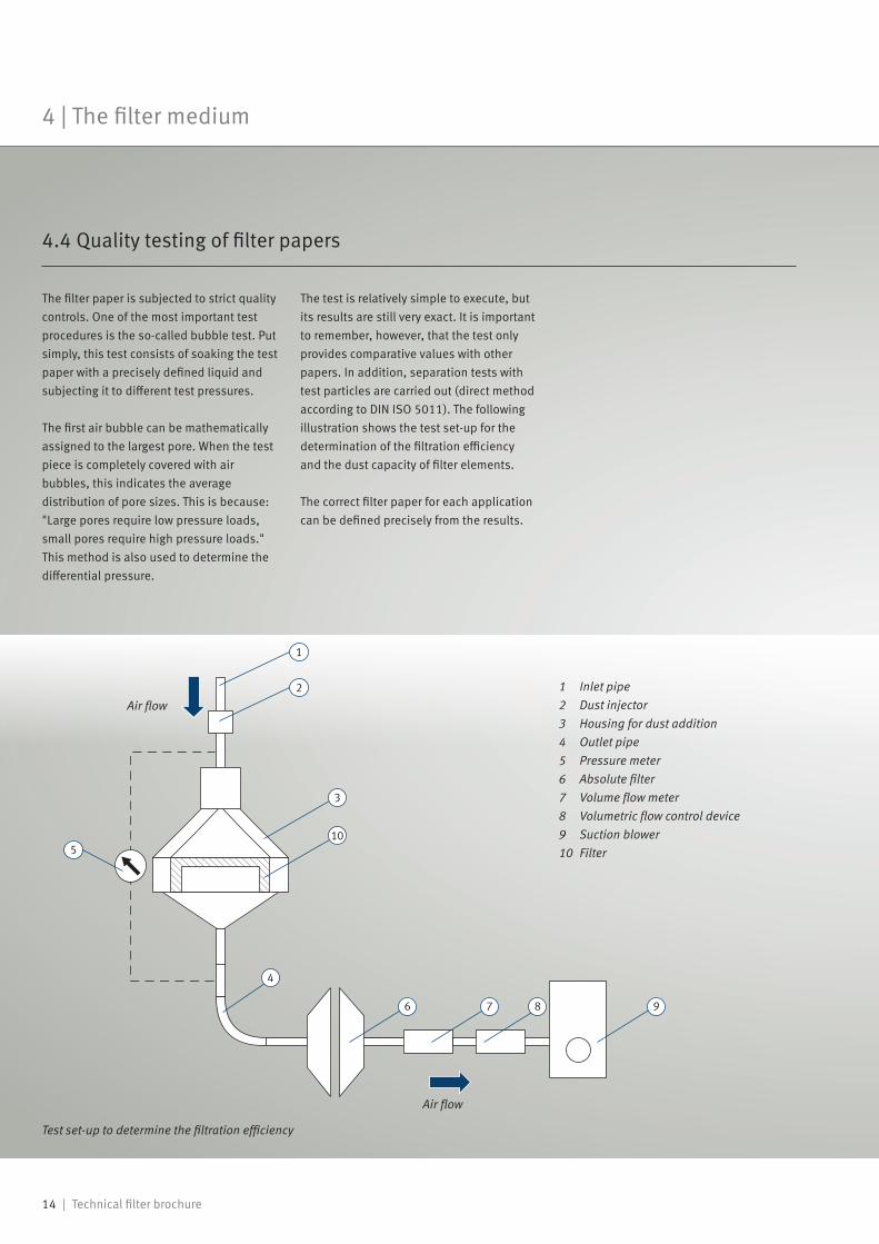
The test is relatively simple to execute, but its results are still very exact. It is important to remember, however, that the test only provides comparative values with other papers. In addition, separation tests with test particles are carried out (direct method according to DIN ISO 5011). The following illustration shows the test set-up for the determination of the filtration efficiency and the dust capacity of filter elements.
The correct filter paper for each application can be defined precisely from the results.
Test set-up to determine the filtration efficiency
Air flow
Air flow1 Inlet pipe2 Dust injector3 Housing for dust addition4 Outlet pipe5 Pressure meter6 Absolute filter7 Volume flow meter8 Volumetric flow control device9 Suction blower10 Filter
4.4 Quality testing of filter papers

Technical filter brochure | 15
Air filters | 5
Air filters purify the intake air and dampen the intake noise of the engine. Another function – especially in passenger cars – is pre-heating the intake air and controlling the temperature. This regulation is key for the operating behaviour of the engine and the exhaust gas composition.
This short numerical example illustrates the capacity and importance of the filter element:
The dirt film which has settled on the filter over a mileage of 15,000 km is clearly visible (Fig. 1). Minute dirt particles settle in the depth structure of the filter paper. Consequences: richer fuel-air mixture, elevated pollutant emission, reduced engine performance.
5.2 Task/function
Depending on the landscape, weather conditions, ground and road properties and the use of the motor vehicle, the amount of dust per m³ of air may range from 1 to 10 mg. On unpaved roads or on construction sites, it may even reach 40 mg.
Assuming that a supply of approximately 14 kg of air is necessary for the complete combustion of one litre of fuel (petrol engine), one gets an idea of how many dust particles have to be filtered out.
This amount of dust, together with the lubricant, can form an abrasive mass which inevitably leads to considerable wear on the pistons, piston rings and running surfaces of the cylinder liners.
When talking about air filters (suction filters) in modern engine manufacture, the main focus lies on the so-called dry filters, the generic term for a variety of exchangeable paper filters. Dry filters work in a different way than wet or oil bath filters,
5.1 Basic information
where liquids are used to separate dust particles from the intake air. The paper filter has gained acceptance for air intake, mainly because it can ensure higher and - above all - stable filtration efficiency for all load ranges. Additional advantages are the easy
maintenance and the independence of the installation position. The paper filter also scores points from an environmental standpoint.
Fig. 1

16 | Technical filter brochure
5 | Air filters
Failure to replace air filters in time leads to a richer fuel-air mixture due to the increasing flow resistance and thus to higher pollutant emissions, as well as reduced engine performance.
Fine dust particles that pass the filter paper contribute to siltation in the engine and may deposit on the air mass sensor.
Air filters for passenger cars come in two different models: panel filters and round filters (round and oval elements). The type of filter suitable in any specific case mainly depends on the application of the basic rules of filter technology.
For their position in the vehicle, the spot with the lowest possible dust or water supply is chosen. The filter elements have a high filtration efficiency, irrespective of the load. They are easy to replace according
This component is installed on the clean air side of the suction filter and is responsible for metering the fuel quantity (increasing fuel consumption).
If dirt particles get into the inside of the combustion chamber, the durability of the combustion engine is reduced, since the engine bearings, pistons, piston rings and
Fig. 1:AP air filter, panel
Fig. 2:AP air filter, round
Fig. 4:Air filter, panel with protective fleece
Fig. 3:AR round air filter for trucks
5.3 Consequential damage
running surfaces of the cylinder liners wear out due to the increased abrasive effect.
5.4 Passenger car air filter design
to the maintenance intervals specified by the vehicle manufacturer.There is a wide range of engines on the market, and each vehicle requires filters which fulfil the requirements of the engine and installation space exactly. Kolbenschmidt offers air filter models to suit virtually any vehicle.
Filter housings and filter elements are optimally coordinated and adjusted to the engine type and its intake system.
One special design is the panel filter with protective fleece (Fig. 4). In addition to the filter paper, the filter is protected by a fleece for rough filtration. This design is predominantly used in areas with a heavy dust load.
Technical filter brochure | 17
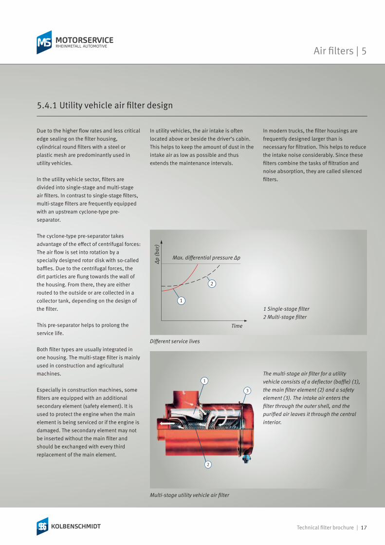
Due to the higher flow rates and less critical edge sealing on the filter housing, cylindrical round filters with a steel or plastic mesh are predominantly used in utility vehicles.
In the utility vehicle sector, filters are divided into single-stage and multi-stage air filters. In contrast to single-stage filters, multi-stage filters are frequently equipped with an upstream cyclone-type pre-separator.
The cyclone-type pre-separator takes advantage of the effect of centrifugal forces: The air flow is set into rotation by a specially designed rotor disk with so-called baffles. Due to the centrifugal forces, the dirt particles are flung towards the wall of the housing. From there, they are either routed to the outside or are collected in a collector tank, depending on the design of the filter.
This pre-separator helps to prolong the service life.
Both filter types are usually integrated in one housing. The multi-stage filter is mainly used in construction and agricultural machines.
Especially in construction machines, some filters are equipped with an additional secondary element (safety element). It is used to protect the engine when the main element is being serviced or if the engine is damaged. The secondary element may not be inserted without the main filter and should be exchanged with every third replacement of the main element.
In utility vehicles, the air intake is often located above or beside the driver‘s cabin. This helps to keep the amount of dust in the intake air as low as possible and thus extends the maintenance intervals.
5.4.1 Utility vehicle air filter design
In modern trucks, the filter housings are frequently designed larger than is necessary for filtration. This helps to reduce the intake noise considerably. Since these filters combine the tasks of filtration and noise absorption, they are called silenced filters.
Different service lives
Time
Δp (b
ar)
Max. differential pressure Δp
1 Single-stage filter2 Multi-stage filter
The multi-stage air filter for a utility vehicle consists of a deflector (baffle) (1), the main filter element (2) and a safety element (3). The intake air enters the filter through the outer shell, and the purified air leaves it through the central interior.
Air filters | 5
Multi-stage utility vehicle air filter

18 | Technical filter brochure
5 | Air filters
The following points must be observed when replacing an air filter:• Never replace the air filter with the engine running.
• Make sure that no dirt particles get into the air ducts when removing the old filter.
• Do not try to clean the old filter using compressed air.
• Choose the right filter. Serious damages may otherwise occur on the engine due to different sealing and permeation properties.
• Follow the instructions given by the manufacturer when installing the new filter.
• Before installation, clean the cover and housing of the new filter using a clean, soft cloth. Do not use a brush or other instruments that might whirl up dirt particles.
• Examine all gaskets for damage. Even small cracks or deformations can lead to considerable contamination. If in doubt, replace the gaskets.
• Place the filter element in the centre.• When mounting the cover, make sure that there is no gap between the cover and the housing because unfiltered air may otherwise enter the combustion chambers.
5.5 Mounting instructions for filter replacement
Note:In case of frequent travel on very
dusty roads, the air filter insert must be exchanged more often than prescribed under normal circumstances.
Air filters

Technical filter brochure | 19
The filter may not be cleaned using compressed air under any circumstances (Fig. 1 and 2). This would press the microscopic dirt particles even further into the depth structure of the filter paper, resulting in an even lower flow rate. In addition, the filter paper may tear due to the high air pressure.
When handling the filter, also take care that the paper pack and the sealing face are not destroyed (Fig. 3 and 4). For this reason, the filter should not be beaten. Insufficient sealing or cracks in the filter paper will result in foreign bodies entering the inside of the engine, which could cause serious damage.
Spoiled or deformed filters may not be fitted under any circumstances (Fig. 5 and 6).
Fig. 1 Fig. 2
Fig. 3 Fig. 4
Fig. 5 Fig. 6
5.6 Handling mistakes
Air filters | 5

20 | Technical filter brochure
6 | Cabin filters
none01-10months light
AlderHazelElmWillowPoplarMapleAshHornbeamBirchPineOakSycamoreBeechGrassesPlantainSorrelRyePigweedGoldenrodLimeNettleMugwortFungal spores
01 02 06 07 08 100903 04 05
moderate heavy very heavy
Installing a Kolbenschmidt cabin filter means comfortable, safe driving:• without watery eyes• without coughing and• without the urge to sneeze.
The first blossoms of springtime bring with them particularly high concentrations of airborne pollen. This is a big problem for allergy sufferers, causing them to battle with runny noses, coughing, shortness of breath and other discomforts. Recent studies indicate that persons with allergies have a significantly higher risk of accidents (up to 30 %).
6.1 Basic information
Not just pollen, but above all the mixture of soot particulates, spores, bacteria and toxic fumes (such as benzene, lead, ozone etc.) pose a hazard for the vehicle occupants. Tests have shown that, without an effective filter, the concentration of suspended particles and harmful substances in the cabin of a vehicle can be up to six times higher than in the open air.
The Kolbenschmidt cabin filter protects the occupants from harmful particles and gases that ordinarily enter the vehicle via the blower: dust, soot and other foreign particles are taken in and absorbed up to 99.5 %. A constant supply of fresh, clean air helps to make the journey pleasant and relaxing for the driver and passengers alike.

Technical filter brochure | 21
Cabin filters | 6
Human concentration and abilities are very strongly influenced by the quality and temperature of the surrounding air. A constant supply of filtered fresh air to the passenger compartment is therefore essential. This air may be heated or cooled depending on the ambient temperature.
The cabin filter is a key part of the air ventilation cycle. It is installed in the air
inlet port of the blower and filters foreign particles such as dust, pollen, soot, etc. out of the air. It has been installed as standard for some years now, and ensures clean fresh air inside the vehicle.
Cabin filters are available in various shapes, sizes and versions to suit different vehicles: rectangular, keystone shaped and round, with and without plastic housing or foam seal.
In order to illustrate the arrangement in the air intake duct, a schematic diagram of an air conditioning system is shown below. The design of an ordinary heating system is similar, but without a condenser.
Fresh air operationOutside air is drawn through the blower. The air grille keeps out leaves, insects and other large material and particulate. The cabin filter installed after that in the duct filters dust, pollen, soot and other foreign particles before the purified air reaches the condenser. It is cooled down here, causing water to condense and be removed to the
outside via run-off tubes. The dry, cool air is subsequently warmed on the heat exchanger to the cabin temperature selected by the driver. From there, it passes through various throttles and nozzles to the desired locations in the cabin.
Recirculation modeIn this operating mode, the air is drawn exclusively from the passenger compartment. After passing through the cabin filter and condenser, the purified air is then returned to the cabin. This operating mode is used primarily in traffic jams or when driving in tunnels.
1 Recirculation mode2 Valve3 Air grille with water droplet separator
attached
Design of an air conditioning system
6.2 Fresh air supply in the vehicle
4 Blower5 Condenser6 Outside air7 Cabin filter
8 Heating / heat exchanger9 Mixing chamber10 Fresh air to the passenger compartment

22 | Technical filter brochure
6 | Cabin filters
There are two types of cabin filter at Kolbenschmidt: the standard filter (AC) and the activated carbon filter (ACC), also referred to as the combination filter.
Designation Filter type
AC (air cabin) Standard cabin filter
ACC (air cabin with activated carbon) Cabin filter with activated carbon
6.4 Standard filter (AC)
703-AC716-AC
In addition to solid particles, the activated carbon filter also filters harmful gases such as nitrogen oxide, sulphur dioxide, ozone and hydrocarbons, and keeps 95 % of these out of the cabin. The activated carbon layer can filter out and absorb the smallest particulates.
Unpleasant odours are also contained, so that smells when driving through tunnels or in traffic jams, for example, are kept to a minimum.
712-ACC715-ACC
723-ACC
6.5 Activated carbon filter/combination filter (ACC)
The standard filter chiefly absorbs solid particles such as pollen, spores, soot, specks of dust, tyre wear particles, etc. from the outside air. It achieves this by means of a specially developed filter medium.
6.3 Types
728-AC

Technical filter brochure | 23
Cabin filters | 6
The activated carbon filter consists of various media arranged in layers: a carrier medium, which gives the filter more mechanical stability, a filter medium and an activated carbon layer (Fig. 1).
The filtration principle of an activated carbon filter is represented schematically in Fig. 2 below: When air passes through, the filter medium retains the solid materials, while the activated carbon layer binds gases and odours.
The combination filter is a frequent alternative to the standard filter. Vehicles previously equipped with an ordinary standard filter can therefore be retrofitted with an activated carbon filter of the same geometry without difficulty. Due to its more comprehensive filtering action, increasing numbers of vehicles today are fitted with an activated carbon filter as standard.
Fig. 2: Filtration principle of an activated carbon filter (combination filter)1 Dirt particles2 Gas molecules3 Dirty air from outside4 Clean air for the interior
Fig. 1: Sectional view of a combination filter1 Filter medium2 Activated carbon layer3 Carrier medium
24 | Technical filter brochure
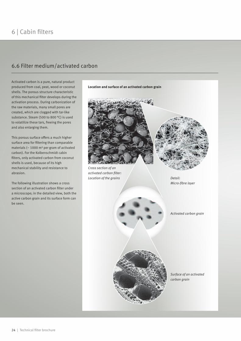
Activated carbon is a pure, natural product produced from coal, peat, wood or coconut shells. The porous structure characteristic of this mechanical filter develops during the activation process. During carbonization of the raw materials, many small pores are created, which are clogged with tar-like substance. Steam (500 to 800 °C) is used to volatilize these tars, freeing the pores and also enlarging them.
This porous surface offers a much higher surface area for filtering than comparable materials (~ 1000 m² per gram of activated carbon). For the Kolbenschmidt cabin filters, only activated carbon from coconut shells is used, because of its high mechanical stability and resistance to abrasion.
The following illustration shows a cross section of an activated carbon filter under a microscope; in the detailed view, both the active carbon grain and its surface form can be seen.
Cross section of an activated carbon filter: Location of the grains
Surface of an activated carbon grain
Location and surface of an activated carbon grain
Detail: Micro-fibre layer
Activated carbon grain
6.6 Filter medium/activated carbon
6 | Cabin filters
Technical filter brochure | 25
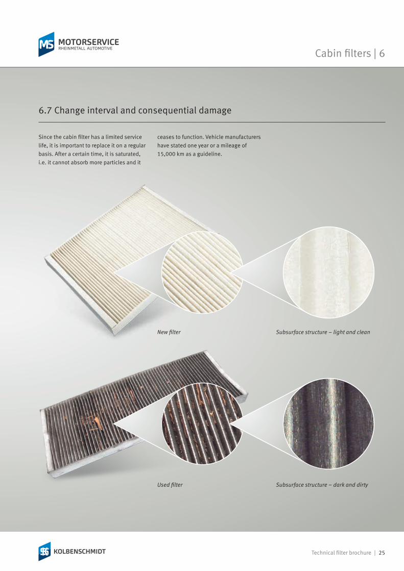
Since the cabin filter has a limited service life, it is important to replace it on a regular basis. After a certain time, it is saturated, i.e. it cannot absorb more particles and it
New filter
Used filter
Subsurface structure – light and clean
Subsurface structure – dark and dirty
6.7 Change interval and consequential damage
ceases to function. Vehicle manufacturers have stated one year or a mileage of 15,000 km as a guideline.
Cabin filters | 6

26 | Technical filter brochure
If the maximum pollutant absorption capacity has been achieved, the normal flow of fresh air is impeded, because the air flow is greatly reduced. Despite running the blower at high settings, the windows fog up and streaks form.
The lower air flow also poses difficulties for the blower, because it must work against the higher resistance of the clogged filter. A filter saturated with dust and other dirt particles also leads to a disagreeable, musty smell in the vehicle cabin and is an ideal breeding ground for microorganisms such as bacteria and moulds.
The latest point at which the filter must be replaced
Time interval or dirt load
Fres
h ai
r sup
ply
t1
Effects on the fresh air supply
If the filter is also damaged, the condenser gets contaminated to a greater degree, reducing the cooling efficiency of the air conditioner and possibly leading to premature failure. The consequence of this is higher repair costs.
Furthermore, bacterial and mould pass unhindered through the blower to the cabin and create a health hazard for its occupants. The seats and interior lining also become disproportionately dirty as a result.
The benefits of a pollen filter can be realized only if the windows and roof of the vehicle remain closed.
In summary, we recommend that the cabin filter be changed without delay at the following indications (or sooner):• Fogged windows despite a high fan setting (streak formation)
• Poor performance of the air conditioning system or the blower
• A musty smell• Tiredness of the occupants• Contamination of the cockpit and interior lining
6 | Cabin filters
Technical filter brochure | 27
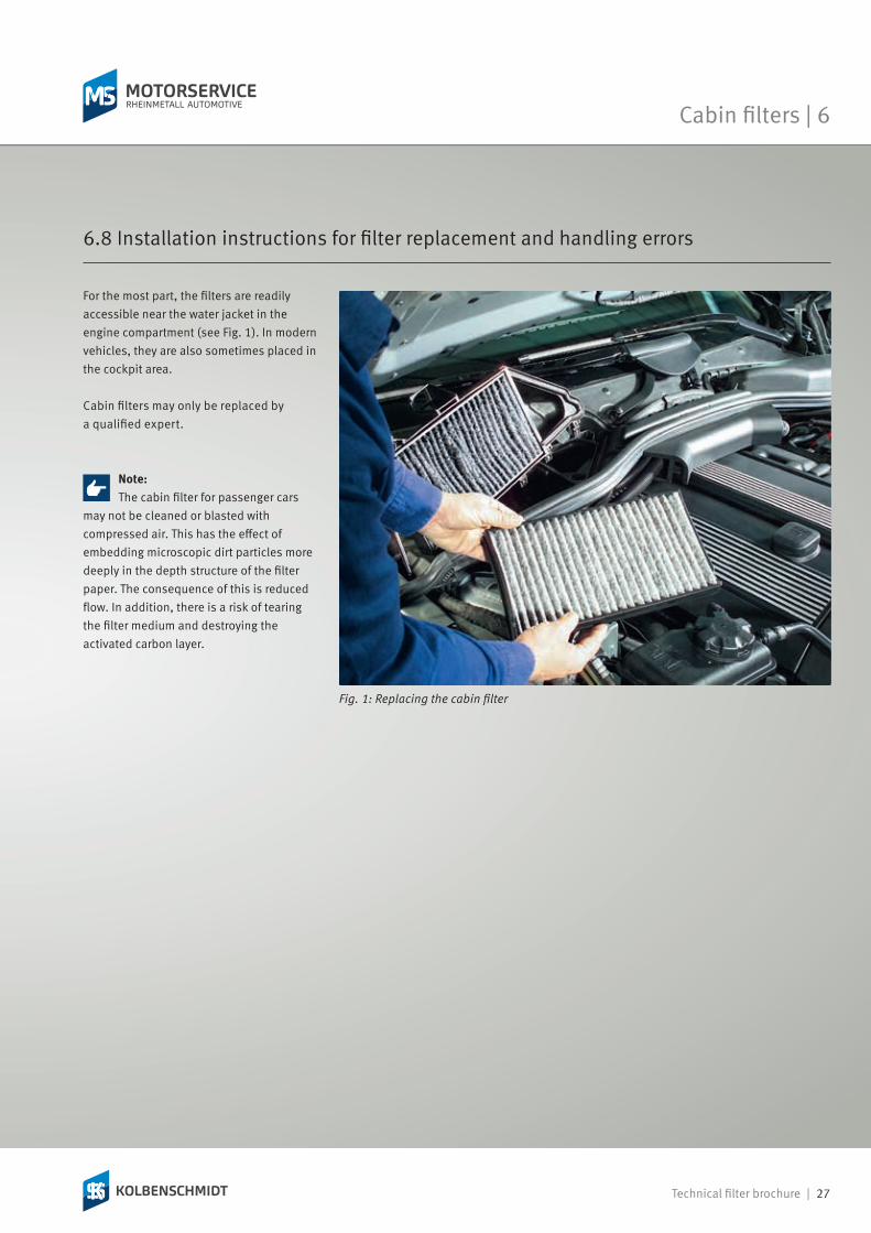
For the most part, the filters are readily accessible near the water jacket in the engine compartment (see Fig. 1). In modern vehicles, they are also sometimes placed in the cockpit area.
Cabin filters may only be replaced by a qualified expert.
Note:The cabin filter for passenger cars
may not be cleaned or blasted with compressed air. This has the effect of embedding microscopic dirt particles more deeply in the depth structure of the filter paper. The consequence of this is reduced flow. In addition, there is a risk of tearing the filter medium and destroying the activated carbon layer.
Fig. 1: Replacing the cabin filter
6.8 Installation instructions for filter replacement and handling errors
Cabin filters | 6

28 | Technical filter brochure
7 | Air dryers for brake systems
The compressed air required for braking is generated by the compressor, which is driven by the engine. The compressed air then flows from the compressor to the single-chamber air dryer for brake systems with pressure regulator. Here, the compressed air is dried by specially developed granulate, and the integrated pressure regulator limits the pressure in the brake system to a set value.
Next, the compressed air enters a compressed air tank, which is equipped with a condensate sensor and a safety valve for monitoring the air drying process.
If water and oil enter the reservoirs and thus the brake system, the consequences will be dangerous and costly damage: The moisture damages the valves, causes corrosion in the pipes and receptacles, and at sub-zero temperatures the complete system may freeze. The oil impairs the function of the valves and thus causes the brake response to deteriorate. This causes an increased load on the brake pads and they wear faster.
Mounting position of the air dryer for brake systems
7.2 Function
7.3 Consequential damage
The air dryer for brake systems should therefore be exchanged regularly as well!
In order to prevent this potential damage and costs, the use of a Kolbenschmidt air dryer for brake systems is highly recommended. The durability of the individual components is improved, and the vehicle downtime is reduced.
The air dryer for brake systems provides a special kind of filtration. It is used, above all, in the compressed air supply system of
7.1 Basic information
medium and heavy utility vehicles. Because compressed air is used to provide the energy for numerous control and regulating
processes in modern vehicles, the air dryer for brake systems is classed as a safety component on the vehicle.
Technical filter brochure | 29
Fuel filters | 8
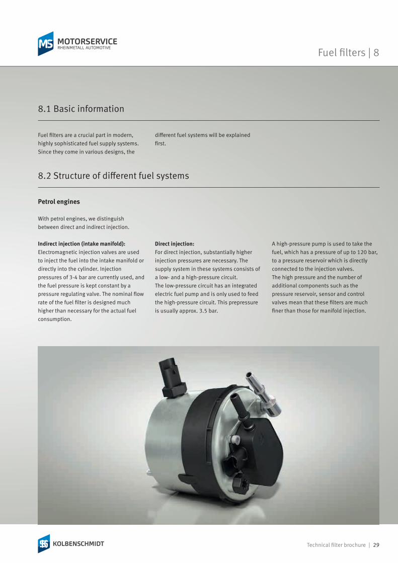
With petrol engines, we distinguish between direct and indirect injection.
Indirect injection (intake manifold):Electromagnetic injection valves are used to inject the fuel into the intake manifold or directly into the cylinder. Injection pressures of 3-4 bar are currently used, and the fuel pressure is kept constant by a pressure regulating valve. The nominal flow rate of the fuel filter is designed much higher than necessary for the actual fuel consumption.
Direct injection:For direct injection, substantially higher injection pressures are necessary. The supply system in these systems consists of a low- and a high-pressure circuit. The low-pressure circuit has an integrated electric fuel pump and is only used to feed the high-pressure circuit. This prepressure is usually approx. 3.5 bar.
8.2 Structure of different fuel systems
Petrol engines
A high-pressure pump is used to take the fuel, which has a pressure of up to 120 bar, to a pressure reservoir which is directly connected to the injection valves. The high pressure and the number of additional components such as the pressure reservoir, sensor and control valves mean that these filters are much finer than those for manifold injection.
Fuel filters are a crucial part in modern, highly sophisticated fuel supply systems. Since they come in various designs, the
8.1 Basic information
different fuel systems will be explained first.

30 | Technical filter brochure
The combustion process in a diesel engine differs considerably from that of a petrol engine. The diesel engine always operates with internal mixture formation and self-ignition of the air-fuel mixture. The term "internal mixture formation" refers to the process of converting liquid fuel into an ignitable mixture after injection.In order to achieve a better and more efficient combustion process, the fuel is directly injected into the cylinder in virtually all modern diesel engines. Pump-nozzle injectors and common rail technology are the most widespread fuel injection systems here.
Diesel engines
Pump-nozzle injectors:In the pump-injector nozzle system, each cylinder head has a pump-nozzle injector. It contains the following components in its housing• the high-pressure piston pump element,• the solenoid valve to control the injection process, as well as
• the injection nozzle with the injection valve.
This system is suitable for injection pressures of up to 2000 bar.
Common rail:Common rail technology uses a high-pressure injection system with electric control with a shared distributing pipe known as the common rail. The fuel is fed to the combustion chambers by injectors which are controlled by solenoid valves. With a high-pressure radial-piston pump, pressures of up to 1600 bar can be reached.
Due to the use of these modern systems, it has become necessary to increase the fineness of fuel filters considerably (Fig. 1).
8 | Fuel filters

Technical filter brochure | 31
Fuel filters | 8
1 Carburettor2 Indirect injection3 Direct injection 4 Pump-nozzle injector5 Common rail0
25
50
75
100
Filtr
atio
n effi
cien
cy (3
–5 µ
m) i
n %
Recommended minimum filter units for petrol and diesel engines
Fig. 1: Common rail
1 High-pressure pump2 Fuel filter3 Pressure sensor4 Common rail5 Pressure relief valve
6 Injectors7 Pressure regulating valve8 Fuel pump9 Fuel tank10 ECU
Low-pressure fuel line High-pressure fuel line Fuel return line

32 | Technical filter brochure
To guarantee the performance of the engine, the fuel filter must effectively protect the fuel system against impurities such as dirt, rust, dust and water contamination. Protecting the high-quality fuel injection system is a vitally important task, particularly in modern diesel injection
Fuel flow
1 Coarse filter2 Fine filter
Multi-stage filters
Fuel flow is divided
1 Two identical filter cartridges
Parallel filters
8.3 Task/function
engines. Even particulates in the order of 5 – 20 μm in size can lead to considerable damage or failure of the engine.
The fuel filter has a finer filter paper than the oil filter since the components of the fuel supply system have smaller running
clearances. In order to prevent even minute dirt particles from entering the pipe circuit, bypass valves are not allowed in fuel filters.
8.5 Consequential damage
Fuel filters must be replaced regularly. If the filter is clogged, the fuel supply of the engine is insufficient and leads to reduced performance. Difficulties in starting occur, the engine stutters and runs out-of-true; there is not enough fuel for acceleration.
If a filter is used which is not suitable for the corresponding application or if the filter installed has quality deficiencies or imperfections, a higher amount of dust can enter the filter element. In petrol engines, this leads to faults in the carburettor or fuel
injection system and causes wear on these components. In diesel engines, the extremely sensitive injection elements are damaged and fail.
8.4 Arrangement of the filters
According to their arrangement, fuel filters are divided into single-stage, multi-stage and parallel filters. With a multi-stage filter, a coarse filter (sieve filter made from metal or plastic) is mounted in front of the fine filter. The parallel filter consists of two identical filter cartridges. Its main advantage over an individual filter is that it allows a greater flow.
8 | Fuel filters
Technical filter brochure | 33
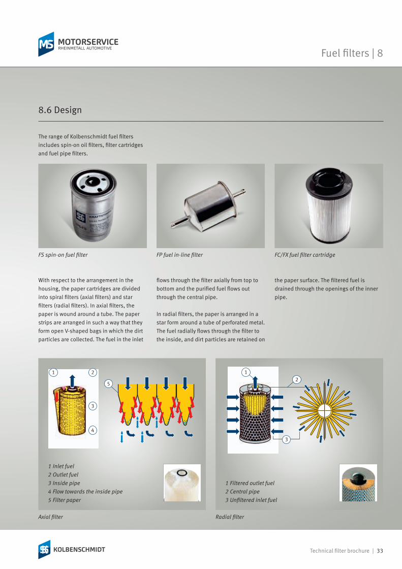
With respect to the arrangement in the housing, the paper cartridges are divided into spiral filters (axial filters) and star filters (radial filters). In axial filters, the paper is wound around a tube. The paper strips are arranged in such a way that they form open V-shaped bags in which the dirt particles are collected. The fuel in the inlet
Radial filter
1 Filtered outlet fuel2 Central pipe3 Unfiltered inlet fuel
Axial filter
1 Inlet fuel2 Outlet fuel3 Inside pipe4 Flow towards the inside pipe5 Filter paper
flows through the filter axially from top to bottom and the purified fuel flows out through the central pipe.
In radial filters, the paper is arranged in a star form around a tube of perforated metal. The fuel radially flows through the filter to the inside, and dirt particles are retained on
the paper surface. The filtered fuel is drained through the openings of the inner pipe.
The range of Kolbenschmidt fuel filters includes spin-on oil filters, filter cartridges and fuel pipe filters.
FS spin-on fuel filter FC/FX fuel filter cartridgeFP fuel in-line filter
8.6 Design
Fuel filters | 8

34 | Technical filter brochure
Structure of a fuel filter
1 Filter medium2 Water level sensor3 Fuel entry point4 Fuel exit point5 Heating module6 Water drain plug7 Electrical connection8 Pressure-stable filter housing9 Water drainage channel10 Protective cage
Filter cartridges can be replaced individually, and are located in a separate housing which is mounted on the engine. During filter replacement, the housing gasket is unscrewed and only the filter element is replaced. Modern filter cartridges are made of materials that are suitable for thermal recycling.Cartridges from paper and felt are used as filter elements.
The inline filters are available as sieve or paper filters and are inserted into the fuel line. Depending on the application, the filter housing is made of aluminium, sheet steel, or plastic.
Sieve filters are e. g. used as prefilters in the fuel tank or in the fuel pump. They consist of a fine wire or polyamide mesh with mesh sizes that vary from 40 to 60 µm.
8.6.2 Fuel pipe filters (inline)
8.6.1 Fuel filter cartridge
8 | Fuel filters
For fine filtration, paper filters between 6 and 10 µm are used. They are usually mounted by just slipping them onto the fuel line.
Filter cartridge from feltFilter cartridge from paper

Technical filter brochure | 35
The filters consist of a housing with a filter element, which are replaced as a unit during maintenance. The filters are normally mounted in the engine compartment or under the vehicle between the fuel tank and the engine.
In passenger cars, filters with water drain plugs and an integrated pressure regulating valve are used in addition to the standard,
replaceable cartridge filters. For utility vehicles, other designs are offered with integrated extra functions such as:• valves or sensors to control the pressure and temperature,
• electric heaters,• heat exchangers, or• water sensors with a water collection chamber.
Always take the utmost care when working on the fuel system. The fuel system often remains under pressure for a long time after the engine was stopped!• Observe the change intervals recommended by the manufacturer.
• Always observe the mounting instructions given by the vehicle manufacturer.
8.7 Mounting instructions for filter replacement
• Use suitable tools for filter replacement.• Pay close attention to the flow direction when installing fuel-line filters. The flow direction is marked with an arrow and should point away from the fuel tank towards the engine.
Note:When replacing the fuel pump,
always replace the filter too. Replacing the relatively cheap filter helps prevent large and expensive repairs!
8.6.3 Spin-on fuel filters
Fuel filters | 8
Water separation function:Because of its very high surface tension, the resulting condensation water in the fuel tank (humidity) is initially held on the dirt side. After the rise in the differential pressure it gets through the pores onto the clean side, where it forms larger droplets. Because of their higher specific weight, these enter the water reservoir.
The reservoir can be emptied by opening the water outlet screw. On some vehicles, the water level can be identified using a sensor.
Spin-on fuel filter
36 | Technical filter brochure
9 | Urea filters
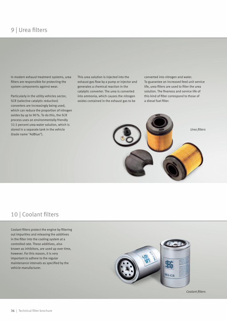
In modern exhaust treatment systems, urea filters are responsible for protecting the system components against wear.
Particularly in the utility vehicles sector, SCR (selective catalytic reduction) converters are increasingly being used, which can reduce the proportion of nitrogen oxides by up to 90 %. To do this, the SCR process uses an environmentally friendly 32.5 percent urea-water solution, which is stored in a separate tank in the vehicle (trade name "AdBlue").
This urea solution is injected into the exhaust gas flow by a pump or injector and generates a chemical reaction in the catalytic converter. The urea is converted into ammonia, which causes the nitrogen oxides contained in the exhaust gas to be
10 | Coolant filters
converted into nitrogen and water. To guarantee an increased feed unit service life, urea filters are used to filter the urea solution. The fineness and service life of this kind of filter correspond to those of a diesel fuel filter.
Urea filters
Coolant filters
Coolant filters protect the engine by filtering out impurities and releasing the additives in the filter into the cooling system at a controlled rate. These additives, also known as inhibitors, are used up over time, however. For this reason, it is very important to adhere to the regular maintenance intervals as specified by the vehicle manufacturer.
Technical filter brochure | 37
Oil filters | 11
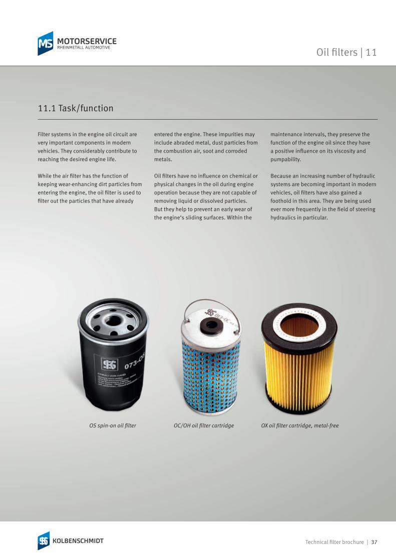
Filter systems in the engine oil circuit are very important components in modern vehicles. They considerably contribute to reaching the desired engine life.
While the air filter has the function of keeping wear-enhancing dirt particles from entering the engine, the oil filter is used to filter out the particles that have already
11.1 Task/function
entered the engine. These impurities may include abraded metal, dust particles from the combustion air, soot and corroded metals.
Oil filters have no influence on chemical or physical changes in the oil during engine operation because they are not capable of removing liquid or dissolved particles. But they help to prevent an early wear of the engine‘s sliding surfaces. Within the
maintenance intervals, they preserve the function of the engine oil since they have a positive influence on its viscosity and pumpability.
Because an increasing number of hydraulic systems are becoming important in modern vehicles, oil filters have also gained a foothold in this area. They are being used ever more frequently in the field of steering hydraulics in particular.
OX oil filter cartridge, metal-freeOS spin-on oil filter OC/OH oil filter cartridge
38 | Technical filter brochure
11 | Oil filters
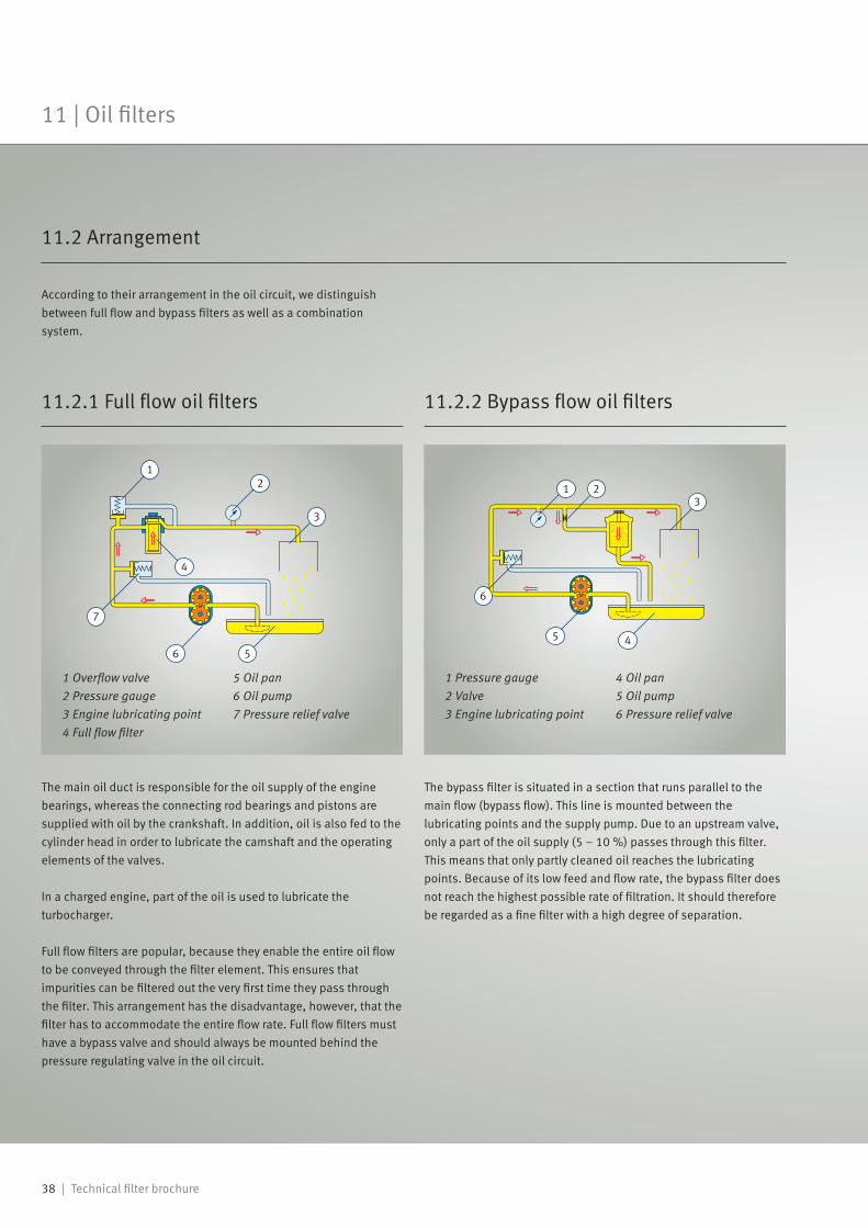
The main oil duct is responsible for the oil supply of the engine bearings, whereas the connecting rod bearings and pistons are supplied with oil by the crankshaft. In addition, oil is also fed to the cylinder head in order to lubricate the camshaft and the operating elements of the valves.
In a charged engine, part of the oil is used to lubricate the turbocharger.
Full flow filters are popular, because they enable the entire oil flow to be conveyed through the filter element. This ensures that impurities can be filtered out the very first time they pass through the filter. This arrangement has the disadvantage, however, that the filter has to accommodate the entire flow rate. Full flow filters must have a bypass valve and should always be mounted behind the pressure regulating valve in the oil circuit.
The bypass filter is situated in a section that runs parallel to the main flow (bypass flow). This line is mounted between the lubricating points and the supply pump. Due to an upstream valve, only a part of the oil supply (5 – 10 %) passes through this filter. This means that only partly cleaned oil reaches the lubricating points. Because of its low feed and flow rate, the bypass filter does not reach the highest possible rate of filtration. It should therefore be regarded as a fine filter with a high degree of separation.
1 Pressure gauge2 Valve3 Engine lubricating point
4 Oil pan5 Oil pump6 Pressure relief valve
1 Overflow valve2 Pressure gauge3 Engine lubricating point4 Full flow filter
5 Oil pan6 Oil pump7 Pressure relief valve
11.2.1 Full flow oil filters 11.2.2 Bypass flow oil filters
According to their arrangement in the oil circuit, we distinguish between full flow and bypass filters as well as a combination system.
11.2 Arrangement

Fz* Fz*
Technical filter brochure | 39
Oil filters | 11
If bypass filters are used in combination with full flow filters, a very effective filtration is achieved: The finest particulates, which are allowed through by the full flow filter, are filtered out by the bypass filter. The bypass filter ensures extremely thorough cleaning with a high level of separation. In utility vehicles and construction machinery, the open jet centrifuge (oil centrifuge filter) is primarily used as a bypass filter. The oil, which is
11.2.3 Oil filters in a combination system
diverted from the main duct into a bypass duct, flows through the hollow shaft of the impeller into the interior of the filter via suitably arranged holes. Specially positioned discharge nozzles in the floor allow the oil back out of the centrifuge.
This process releases recoil forces that cause the impeller to rotate. Here, speeds of 4000 to 8000 rpm can be reached, depending on the pressure and
temperature. The centrifugal forces generated during this rotation fling the dirt particles in the oil onto the inside wall of the impeller. They remain stuck there until the centrifuge is replaced at the next specified maintenance interval.
Oil filter in the combination system
1 Oil cooler2 Valve3 Full flow filter4 Overflow valve5 Lubricating point6 Bypass filter7 Oil pan8 Pressure relief valve9 Oil pump
Free jet centrifuge
1 Oil outlet holes2 Bearing3 Impeller4 Dirt layer5 Bypass duct6 Full flow filter7 Oil flow8 Hub with specially
positioned discharge nozzles
9 Hollow shaft
4000 – 8000 rpm
* CF = centrifugal force
Oil filters

40 | Technical filter brochure
Abrasive dirt particles that have entered the inside of the engine due to insufficient filtration may cause scores on pistons and piston rings as well as bulgy cylinder wear. This mainly affects the sharp edges of the piston rings (see chapter 1.5, Wear on engine components). Due to insufficient sealing of the combustion chamber, the pressure in the crankcase is increased by combustion gases that pass the piston. This excess pressure causes a loss of oil at the
sealing points and oil leakages at the intake valve guides.
Another consequence is reduced compression and engine performance. The connecting rod and crankshaft bearings can also be substantially affected by the abrasive effects of the dirt particles. A higher bearing clearance caused by abrasion reduces their supporting capacity and may lead to bearing damage.
11.3 Consequential damage
11 | Oil filters

Technical filter brochure | 41
Spin-on oil filters consist of a filter bowl (made from sheet steel), a filter element and a flanged or welded on filter cover. The hole filter element is exchanged when replacing the filter. Many replaceable cartridge filters are additionally equipped with a so-called bypass valve (overflow valve) as well as an anti drain valve. This type of filter is used in passenger cars, as well as in utility vehicles.
11.4 Spin-on oil filters
Bypass valveThe bypass valve is also known as overflow valve. It opens a direct passage to the oil circuit in case of elevated oil pressure. This allows unfiltered oil to reach the circuit, but this is better than completely interrupting the lubricating oil supply. The bypass valve can be installed in front of the full flow valve or - as in many Kolbenschmidt filters – directly into the filter element. The adjustment value of the opening pressure is approx. 1–2 bar in practice depending on the application.
The set value can be exceeded during the cold running phase of the engine (highly viscous oil) or if the filter is very dirty and has reached the end of its service life.
Anti drain valveThe anti drain valve is another design characteristic of replaceable cartridge filters. It may be inserted in the supply or outlet line, depending on the installation position of the oil filter. It prevents the oil filter from running empty when the engine idling.
Structure of a spin-on oil filter1 Bypass valve2 Filter bowl3 Supporting pipe
4 Filter cover5 Anti drain valve6 Filter medium
Oil filters | 11

42 | Technical filter brochure
11 | Oil filters
In contrast to the spin-on oil filter, the filter housing is either bolted to the engine, or it is an integral part of the crankcase here. Only the filter cartridge is replaced with this type of filter. In modern vehicles, these filters are made of metal-free materials. Thanks to their environmentally-friendly disposal, these filters are gaining more and more importance.
Advantages of metal-free filters at a glance:• Only the filter cartridge is replaced during a service. The filter housing and valves remain permanently on the engine block.
• Clean replacement of the filter cartridge, the skin does not come into contact with used oil.
• Coordinated with extended maintenance intervals.
• Conservation of resources through utilisation of recycling material. The filter cartridge only consists of the filter medium and thermoplastic end disks.
11.5 Housing filters
• Energetic recovery of the filter cartridge. The energy stored in the filter cartridges is recovered during combustion.
• Drastic reduction of service and disposal costs. The metal- and glue-free filter cartridges do not have to be subjected to an expensive disassembly process. The complete filter cartridge is suitable for thermal recycling.
Housing filter

Technical filter brochure | 43
Oil filters | 11
If a filter is bent or swollen, poor filter quality is often assumed. However, this is very rarely the case. A deformed filter is mostly a symptom of problems in the oil circuit.
The fault is often caused by the pressure regulating valve, which is usually integrated in the oil pump. The oil pump supplies the required oil pressure in the lubricating system to form the lubricating film between the engine compartments. The task of the pressure regulating valve is to keep the pressure in the lubricating system at a particular value. After the valve is opened,
the pressure in the lubricating system remains almost constant. If the pressure regulating valve is jammed or reacts slowly when the engine is started, an inadmissible excess pressure is generated in the system.
If the valve does not open at all, the pressure continues to increase and deforms the weakest part in the system – the filter: The gasket is cracked and the fold breaks if the filter is mounted very tightly. Since this usually also causes a leakage of engine oil, the engine must immediately be stopped to prevent more serious damage.
1 Standard oil filter2 Bent oil filter
Deformed oil filter
1 Lubricating point2 Spin-on oil filter3 Pressure regulating valve open4 Oil return5 Normal pressure6 Pump7 Bypass valve (usually closed)
Functional diagram of a lubricating system
11.6 Failure of the oil filter due to excess pressure

44 | Technical filter brochure
No oil change without filter replacement: With each oil change, the oil filter must always be replaced. • Drain the engine oil with the engine at operating temperature so that the oil pan is emptied completely and as many foreign bodies as possible are washed out.
• Use special spanners as releasing tools.• Completely remove all fragments of gaskets from the engine‘s mounting face and carefully clean the mounting faces.
• Thoroughly clean the filter housings of filter cartridges.
• Always use new gaskets which are included in the scope of supply. If the old gasket is re-used, proper sealing cannot be ensured.
• Spread engine oil onto the gaskets. Never use lubricating grease for this. Components in the grease can attack the O-rings in the filter.
• Do not twist the filter when putting it onto the thread.
• Check that all gaskets are correctly fitted before tightening.
• Only screw the filters manually, do not use tools.
• Check the oil level.• Start the engine and check the circuit for leaks during idling.
11.7 Mounting instructions for filter replacement
11 | Oil filters

Technical filter brochure | 45
Gear oil filters | 12
The gear oil filter is responsible for preventing foreign bodies from entering the automatic transmission unit.
Special oils for automatic transmission units must satisfy additional requirements to oils for manual gearboxes. As well as lubricating tooth surfaces, planet gears and the bearing sliding surfaces, the oil is also used for operating brake bands and clutches. The transmission of torque from the pump to the turbine impeller is also a task of the transmission oil.
Through the optimal filtration of wear-inducing substances, such as metal swarf caused by abrasion, the transmission filter extends the service life of the transmission and improves performance.
Kolbenschmidt filters are produced using continuously monitored state-of-the-art manufacturing processes. Only these stringent measures can ensure that they meet the high requirements of modern precision engines. In the field of filters in particular, the quality is not obvious at first glance. It is not easy to see if a filter will meet the desired performance requirements. All Kolbenschmidt filters at least fulfil the OE requirements. This ensures optimal protection for the engine and a long service life.
The paper used for Kolbenschmidt filters is impregnated and subjected to pressure-proof glueing or clasping.
The pleat geometry, specifically designed for each application, ensures regular spacing between the pleats and an optimal utilization of the filter surface. In constant controls during the manufacturing process, Kolbenschmidt filters have to demonstrate their quality at any time. They are reliable and efficient. Precise processing methods ensure optimal fit precision: Mounting is easy because the gaskets and O-rings needed for installation are included in the scope of supply.
With Kolbenschmidt filters you avoid premature abrasive engine wear, prevent high fuel consumption and poor engine performance, as well as poor emission figures.
Note: So, remember to change filters
regularly.
A wide product range of reliable first-class Kolbenschmidt filters is available for European vehicle applications.
13 Concluding remarks
So choose Kolbenschmidt oil filters, air filters and fuel filters.
Gear oil filters

46 | Technical filter brochure
Glossary
Absolute filterComponent in the testing procedure according to DIN ISO 5011: Downstream filter installed to separate the amount of dust that has passed through the test piece.
AdditiveChemical substance added to liquids to obtain certain properties or to improve performance characteristics.
Anti drain valveValve that prevents the oil from flowing back through the inlet hole after the engine has stopped.
barMetric measuring unit of pressure: 1 bar = 10² kPa.
Blow-by-gasLeakage gas flow that enters the crankcase due to insufficient sealing between the pistons, piston rings, and cylinder wall.
Brownian molecular movementIrregular zigzag motion of microscopic particles (e.g. dust particles) when suspended in gases or liquids, discovered by English botanist Robert Brown; the motion is caused by irregular collisions with the molecules of the surrounding medium.
Burst pressurePressure difference at which a filter or filter component is destroyed due to the internal pressure load.
Bypass valveAlso called overflow valve. Usually installed in the filter, the bypass valve offers protection in case of excess pressure.
Centrifugal forceThe force that acts outwards on any body as it rotates and is directed away from the axis of rotation.
Differential pressure ∆pPressure difference between the filter inlet and outlet.
Dirt-holding capacityamount of dirt a filter medium can hold before reaching a specified differential pressure.
Filter finenessDiameter of particulates which are just small enough to pass through the pores of the filter medium.
Filter service lifeUsage period of a filter or element until maintenance or replacement.
Filtration efficiencyPercentage of particles a filter can separate. A distinction is made between:• Total degree of separation: Refers to all dirt particles without distinction between different grain sizes.
• Fractional degree of separation: This measurement unit requires the indication of the distribution of grain sizes.
µm (micron/micrometer) Metric measuring unit 1 µm = 0.001 mm.
Van-der-Waals forcesforces of attraction between neutral molecules, especially in case of close approximation.
ViscosityGlutinous nature of liquids resulting from an internal friction between molecules, temperature-dependent.

Technical filter brochure | 47
Professional knowledge from the experts
Know-how Transfer
PI 1575
Engine bearings with polymer coating
Systemkomponenten und Service für eine fachgerechte Reparatur
SI 1210For technical personnel only!
ww
w.m
s-m
otor
serv
ice.
com
© M
S M
otor
serv
ice
Inte
rnat
iona
l Gm
bH –
–
04/
15 E
N
Page 1/2
Tips and tricks ...…for correct installation and long service life of the new short block
• Please note that cylinder heads which may be included in the delivery are not fully assembled. These must be aligned with the exhaust manifold or intake manifold and the cylinder head bolts must be tightened according to the
• Clean all attachments thoroughly before installation and check for damage.
• Clean oil cooler thoroughly and check for blockages, it is imperative to replace this in the case of previous engine damage.
•
• Check connections and intake pipes to the engine for tightness.
• Check injection system, set start of delivery according to manufacturer's
• Check the correct operation of the vis-cous fan.
• Clean water cooler and check for blocka-
charge air cooler thoroughly and check for blockages, it is imperative to replace this in the case of previous turbocharger damage.
• Check engine monitoring instruments for correct operation and replace in case of defects.
• Never start the engine without oil and coolant.
• Manually supply (inject) the engine oil
with oil and crank without injection nozzles (max. 10–15 seconds per sequence to avoid damage to the starter)
until oil pressure has built up, so that all bearing points have been supplied with oil before initial start-up.
• Check for correct function in the oil pump, oil pressure control valve, water pump and vibration damper.
• -
cle manufacturer.
Worldwide training Direct from the manufacturer
OnlineShop Your direct access to our products
Technical informationFrom practical experience for practical use
News Regular information via e-mail
Technical videosProfessional installation clearly illustrated
Products in Focus online Get information on the products online
Social media Always up to date
Individual information Especially for our customers
Motorservice app Access technical know-how on the move
Technipedia Are you looking for technical information relating to engines?
www.ms-motorservice.com

50 003 596-02 – EN – 10/14 (062017)© MS Motorservice International GmbH
Motorservice appMobile access to
technical know-how
Find out more
www.ms-motorservice.com/app
Headquarters:MS Motorservice International GmbHWilhelm-Maybach-Straße 14–1874196 Neuenstadt, Germanywww.ms-motorservice.com
Motorservice Partner: