technical information manual · technical information manual mod. vme8200 7 august 2013 ... 33 6.4...
TRANSCRIPT

Technical
Information
Manual
MOD. VME8200
7 August 2013
Revision n.2
VME64X 21 Slot 9U Crate Series
NPO: 00xxx/0x:8200x.MUTx/02

CAEN will repair or replace any product within the guarantee period if the Guarantor declares that the product is defective due to workmanship or materials and has not been caused by mishandling, negligence on behalf of the User, accident or any abnormal conditions or operations.
CAEN declines all responsibility for damages or injuries caused by an improper use of the Modules due to negligence on behalf of the User. It is strongly recommended to read thoroughly the CAEN User's Manual before any kind of operation.
CAEN Technologies reserves the right to change partially or entirely the contents of this Manual at any time and without giving any notice.
Disposal of the Product The product must never be dumped in the Municipal Waste. Please check your local regulations for disposal of electronics products.
Document type: Title: Revision date: Revision: User's Manual (MUT) Mod. VME8200 VME64X 21 Slot 9U Crate Series 07/08/2013 2
NPO: Filename: Number of pages: Page: 00xxx/0x:8200x.MUTx/02 VME8200_REV2.DOCX 38 3
TABLE OF CONTENTS 1. GENERAL DESCRIPTION ..................................................................................................6
1.1 OVERVIEW ........................................................................................................................6
2. TECHNICAL SPECIFICATIONS ..........................................................................................8
2.1 TECHNICAL SPECIFICATION TABLE .........................................................................................8 2.2 VME8200 MECHANICAL DESIGN ..........................................................................................9 2.3 VME8200 BACKPLANE ..................................................................................................... 10 2.4 VME8200 BIN POWER CONNECTOR.................................................................................... 11
3. POWER SUPPLY SECTION .............................................................................................. 12
3.1 POWER CONNECTOR SECTION............................................................................................ 13 3.2 VME8200 POWER DISTRIBUTION........................................................................................ 14 3.3 POWER FACTOR CORRECTION MODULE (PFC) ..................................................................... 14 3.4 MAINS VOLTAGE AND CONNECTION ..................................................................................... 15 3.5 POWER SUPPLY SPECIFICATIONS ........................................................................................ 16
3.5.1 Power Factor Correction Module .............................................................................. 16 3.5.2 Power Modules ....................................................................................................... 16
3.6 FAN TRAY / CONTROL CONNECTOR SPECIFICATIONS ............................................................. 20 3.7 SENSE / SIGNAL CONNECTOR SPECIFICATIONS ..................................................................... 20
4. FAN TRAY SECTION ........................................................................................................ 22
4.1 FAN TRAY FRONT PANEL ................................................................................................... 22 4.1.1 Fan tray Front panel connectors ............................................................................... 22 4.1.2 CAN bus connector Specifications ............................................................................ 23 4.1.3 RS-232 Connector Specifications ............................................................................. 23 4.1.4 Ethernet LAN Connector Specifications..................................................................... 24 4.1.5 FAIL Connector Specifications.................................................................................. 24
5. V8200 OPERATING .......................................................................................................... 26
5.1 TURNING ON/OFF ........................................................................................................... 26 5.2 ALARM AND TRIP OFF ........................................................................................................ 26 5.3 FAN TRAY LOCAL PROGRAMMING ....................................................................................... 26
5.3.1 List of menu functions .............................................................................................. 27 5.4 FAN TRAY REMOTE CONNECTION ....................................................................................... 30
5.4.1 Configure Ethernet connection On a Local Area Network with DHCP Server .............. 30
6. SOFTWARE OVERVIEW .................................................................................................. 31

Document type: Title: Revision date: Revision: User's Manual (MUT) Mod. VME8200 VME64X 21 Slot 9U Crate Series 07/08/2013 2
NPO: Filename: Number of pages: Page: 00xxx/0x:8200x.MUTx/02 VME8200_REV2.DOCX 38 4
6.1 FAN TRAY ETHERNET CONNECTION ....................................................................................31 6.2 CONNECTION CONFIGURATION ............................................................................................31 6.3 VME8200_MANAGER STATUS/SET WINDOW ........................................................................32
6.3.1 VME8200_Manager VME System Reset operation ....................................................33 6.4 FAN TRAY RS232 /USB CONNECTION ................................................................................33
6.4.1 FAN Tray USB connection........................................................................................33
7. COMMUNICATION PROTOCOL........................................................................................36
7.1 MONITOR COMMANDS RELATED TO CHANNEL 'X' : ..................................................................36 7.2 SET COMMANDS RELATED TO CHANNEL 'X' : ..........................................................................36 7.3 MONITOR COMMANDS RELATED TO CRATE (CHANNEL 8) : ......................................................37 7.4 SET COMMANDS RELATED TO CRATE (CHANNEL 8) : .............................................................38
LIST OF FIGURES FIG. 1.1: THE MOD. VME8200 21-SLOT 9U VME64 CRATE ............................................................... 7 FIG. 2.1: MOD VME8200 FRONT AND REAR VIEW ............................................................................. 9 FIG. 2.2: MOD VME8200 BACKPLANE LAYER STACK-UP ...................................................................10 FIG. 2.3: MOD VME8200 BIN POWER CONNECTORS VME64X ..........................................................11 FIG. 3.1: MOD. V81XX POWER SUPPLIES FRONT AN REAR VIEW .......................................................12 FIG. 3.2: MOD. V81XX POWER SUPPLIES COMPONENTS ..................................................................13 FIG. 3.3: MOD. V81XX POWER CONNECTOR...................................................................................13 FIG. 3.4: MOD. V81XX VME64X CONFIGURATION...........................................................................14 FIG. 3.5: MOD. V81XX HIRSCHMANN CONNECTOR ..........................................................................15 FIG. 3.6: POWER MODULE RIPPLE AND NOISE MEASURED AT THE OUTPUT CONNECTOR (@ 5V, 110A) .....18 FIG. 3.7: POWER MODULE RIPPLE AND NOISE MEASURED AT LOAD 0.5 M WIRE (@ 5V, 110A) ................18 FIG. 3.8: POWER MODULE RIPPLE AND NOISE MEASURED AT THE OUTPUT CONNECTOR (@ 12V, 20A) .....19 FIG. 3.9: : POWER MODULE RIPPLE AND NOISE MEASURED AT LOAD 0.5 M WIRE (@ 12V, 20A) ...............19 FIG. 3.10: FAN TRAY / CONTROL CONNECTOR ( 9-PIN DSUB FEMALE) ................................................20 FIG. 3.11: SENSE / SIGNAL CONNECTOR ( 37-PIN DSUB FEMALE) ......................................................20 FIG. 4.1: MOD. VME8200 FAN TRAY FRONT VIEW .........................................................................22 FIG. 4.2: CAN BUS CONNECTOR ..................................................................................................23 FIG. 4.3: RS-232 CONNECTOR (CONNECTOR 9-PIN DSUB FEMALE) ...................................................23 FIG. 4.4: ETHERNET LAN CONNECTOR ..........................................................................................24 FIG. 4.5: FAIL OUTPUT CIRCUIT ....................................................................................................24 FIG. 4.6: FAIL SIGNAL TIMING .......................................................................................................25 FIG. 6.1: MOD. VME8200_MANAGER OPEN WINDOW ......................................................................31 FIG. 6.2: MOD. VME8200_MANAGER COONECTION MENU................................................................31
Document type: Title: Revision date: Revision: User's Manual (MUT) Mod. VME8200 VME64X 21 Slot 9U Crate Series 07/08/2013 2
NPO: Filename: Number of pages: Page: 00xxx/0x:8200x.MUTx/02 VME8200_REV2.DOCX 38 5
FIG. 6.3: MOD. VME8200_MANAGER CONNECTION WINDOW............................................................ 31 FIG. 6.4: MOD. VME8200_MANAGER STATUS/SET WINDOW (POWER OFF) ......................................... 32 FIG. 6.5: MOD. VME8200_MANAGER STATUS/SET WINDOW (POWER ON) .......................................... 32
LIST OF TABLES TABLE 1.1: MOD. MODEL VME8200 VERSIONS .................................................................................7 TABLE 2.1: MOD. VME8200 CRATE FAMILY TECHNICAL FEATURES .......................................................8 TABLE 3.1: MODEL V8101 – V8111 .............................................................................................. 12 TABLE 3.2: AVAILABLE POWER MODULES: ...................................................................................... 13 TABLE 3.3: MOD. V81XX VOLTAGES AND POWER MODULES CONFIGURATIONS ..................................... 14 TABLE 3.4: MOD. VME8200 MAX CURRENT PER SLOT ..................................................................... 14 TABLE 3.5: HIRSCHMANN CONNECTOR CABLING .............................................................................. 15 TABLE 3.6: MOD. VME8200 POWER FACTOR CORRECTION MODULE SPECIFICATIONS .......................... 16 TABLE 3.7: MOD. VME8200 POWER MODULE (+5V +3.3V) TECHNICAL SPECIFICATIONS ....................... 17 TABLE 3.8: MOD. VME8200 POWER MODULE (+12V -12V) TECHNICAL SPECIFICATIONS....................... 17 TABLE 5.1: MOD. VME8200 FAN TRAY MENU ............................................................................... 28 TABLE 5.2: MOD. VME8200 FAN TRAY SUB MENU......................................................................... 29
Document type: Title: Revision date: Revision: User's Manual (MUT) Mod. VME8200 VME64X 21 Slot 9U Crate Series 07/08/2013 2
NPO: Filename: Number of pages: Page: 00xxx/0x:8200x.MUTx/02 VME8200_REV2.DOCX 38 6
1. General description
1.1 Overview The VME 8200 crates are based on a modularity concept and consist of three detachable parts:
• The Subrack (Bin + Backplane): Mod V8200/XX 9U Bin 19”x9U enclosure for 21 VME64x bus cards 6U x 160mm equipped with monolithic 6U VME64X backplane (J1, J2, J0)
• The rear J2/J0 area of the VME backplane is available for 21 6Ux80mm (or 3Ux80mm) rear transition modules (RTM)
• The Pluggable VME Power Supply with different configurations, allows up to 2500W output
• The Pluggable ventilation and control unit (2U Fan Tray): Mod A8160 Smart VME Fan Unit, with OLED display and various interfaces
• The Pluggable air filter (1U)
The power supply is placed in the bottom, behind the fan tray unit, in order to keep the rear of the VME backplane completely accessible.
Safety features include: short circuit protection, Over / Under voltage protection, Over temperature protection. Remote monitoring and control take place through CAN bus, Ethernet, USB and RS232 interfaces. The crates are also SBC controlled via graphic OLED Display, provide Automatic Daisy Chain and support Chained Block Transfer (CBLT). User-friendly control software completes the VME 8200 features. The Unit is powered by 92 ÷264 Vac, 50 ÷ 60 Hz, power factor 0.98% (230Vac).
Document type: Title: Revision date: Revision: User's Manual (MUT) Mod. VME8200 VME64X 21 Slot 9U Crate Series 07/08/2013 2
NPO: Filename: Number of pages: Page: 00xxx/0x:8200x.MUTx/02 VME8200_REV2.DOCX 38 7
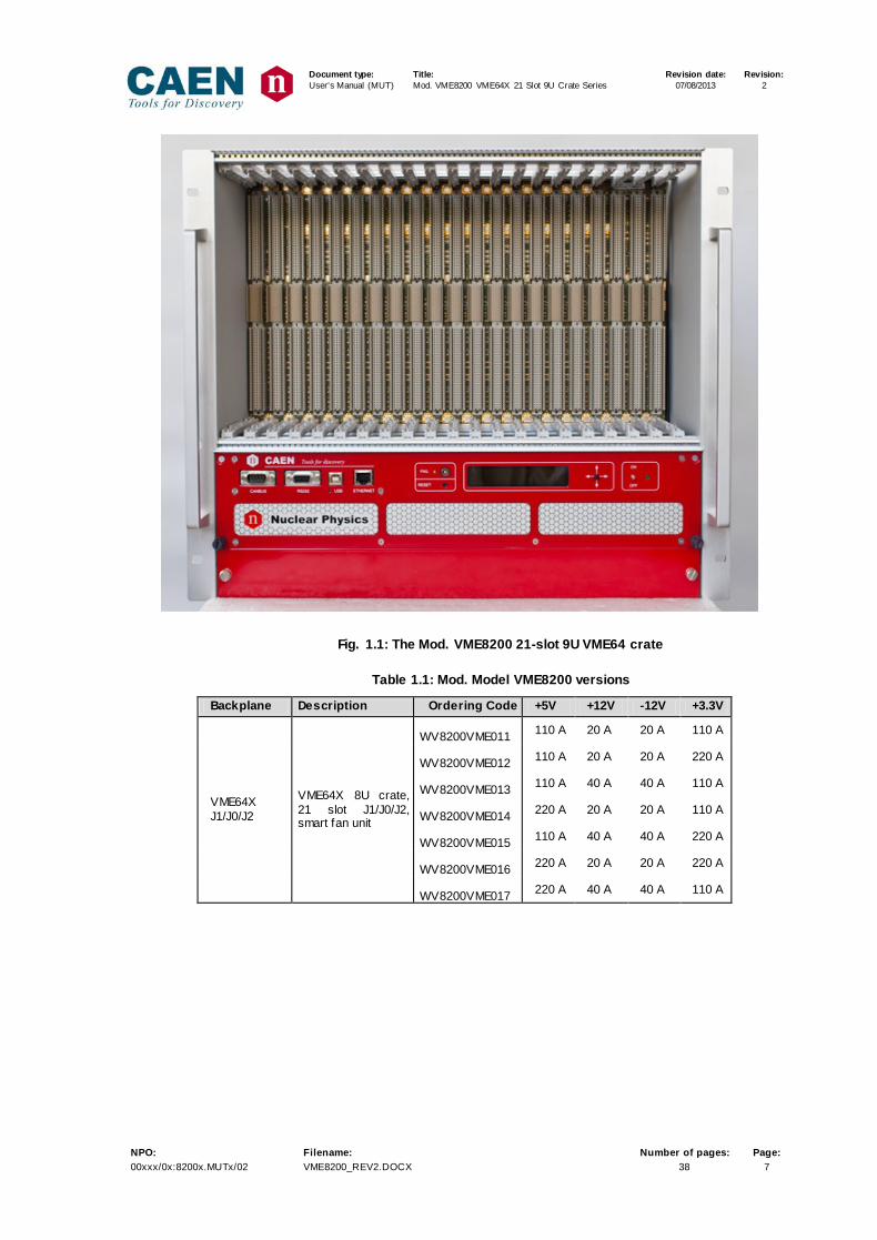
Fig. 1.1: The Mod. VME8200 21-slot 9U VME64 crate
Table 1.1: Mod. Model VME8200 versions
Backplane Description Ordering Code +5V +12V -12V +3.3V
VME64X J1/J0/J2
VME64X 8U crate, 21 slot J1/J0/J2, smart fan unit
WV8200VME011 110 A 20 A 20 A 110 A
WV8200VME012 110 A 20 A 20 A 220 A
WV8200VME013 110 A 40 A 40 A 110 A
WV8200VME014 220 A 20 A 20 A 110 A
WV8200VME015 110 A 40 A 40 A 220 A
WV8200VME016 220 A 20 A 20 A 220 A
WV8200VME017 220 A 40 A 40 A 110 A
Document type: Title: Revision date: Revision: User's Manual (MUT) Mod. VME8200 VME64X 21 Slot 9U Crate Series 07/08/2013 2
NPO: Filename: Number of pages: Page: 00xxx/0x:8200x.MUTx/02 VME8200_REV2.DOCX 38 8
2. Technical specifications
2.1 Technical specification table
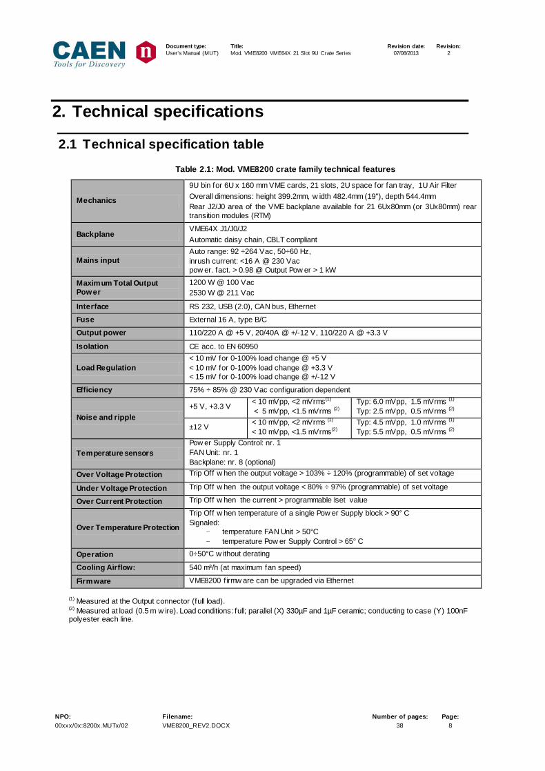
Table 2.1: Mod. VME8200 crate family technical features
Mechanics
9U bin for 6U x 160 mm VME cards, 21 slots, 2U space for fan tray, 1U Air Filter Overall dimensions: height 399.2mm, w idth 482.4mm (19”), depth 544.4mm Rear J2/J0 area of the VME backplane available for 21 6Ux80mm (or 3Ux80mm) rear transition modules (RTM)
Backplane VME64X J1/J0/J2 Automatic daisy chain, CBLT compliant
Mains input Auto range: 92 ÷264 Vac, 50÷60 Hz, inrush current: <16 A @ 230 Vac pow er. fact. > 0.98 @ Output Pow er > 1 kW
Maximum Total Output Power
1200 W @ 100 Vac 2530 W @ 211 Vac
Interface RS 232, USB (2.0), CAN bus, Ethernet
Fuse External 16 A, type B/C
Output power 110/220 A @ +5 V, 20/40A @ +/-12 V, 110/220 A @ +3.3 V
Isolation CE acc. to EN 60950
Load Regulation < 10 mV for 0-100% load change @ +5 V < 10 mV for 0-100% load change @ +3.3 V < 15 mV for 0-100% load change @ +/-12 V
Efficiency 75% ÷ 85% @ 230 Vac configuration dependent
Noise and ripple +5 V, +3.3 V < 10 mVpp, <2 mVrms(1)
< 5 mVpp, <1.5 mVrms (2) Typ: 6.0 mVpp, 1.5 mVrms (1) Typ: 2.5 mVpp, 0.5 mVrms (2)
±12 V < 10 mVpp, <2 mVrms (1)
< 10 mVpp, <1.5 mVrms(2) Typ: 4.5 mVpp, 1.0 mVrms (1)
Typ: 5.5 mVpp, 0.5 mVrms (2)
Temperature sensors Pow er Supply Control: nr. 1 FAN Unit: nr. 1 Backplane: nr. 8 (optional)
Over Voltage Protection Trip Off w hen the output voltage > 103% ÷ 120% (programmable) of set voltage
Under Voltage Protection Trip Off w hen the output voltage < 80% ÷ 97% (programmable) of set voltage
Over Current Protection Trip Off w hen the current > programmable Iset value
Over Temperature Protection
Trip Off w hen temperature of a single Pow er Supply block > 90° C Signaled:
- temperature FAN Unit > 50°C - temperature Pow er Supply Control > 65° C
Operation 0÷50°C w ithout derating
Cooling Airflow: 540 m³/h (at maximum fan speed)
Firmware VME8200 f irmw are can be upgraded via Ethernet
(1) Measured at the Output connector (full load). (2) Measured at load (0.5 m w ire). Load conditions: full; parallel (X) 330µF and 1µF ceramic; conducting to case (Y) 100nF polyester each line.
Document type: Title: Revision date: Revision: User's Manual (MUT) Mod. VME8200 VME64X 21 Slot 9U Crate Series 07/08/2013 2
NPO: Filename: Number of pages: Page: 00xxx/0x:8200x.MUTx/02 VME8200_REV2.DOCX 38 9
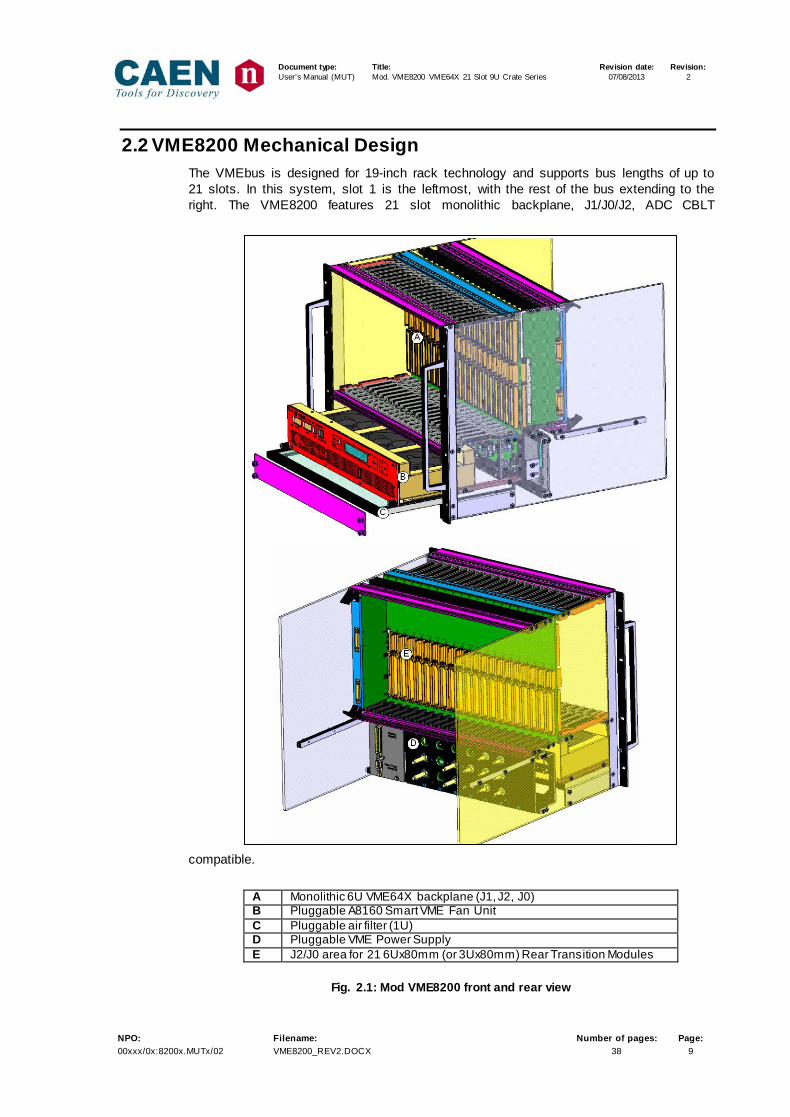
2.2 VME8200 Mechanical Design The VMEbus is designed for 19-inch rack technology and supports bus lengths of up to 21 slots. In this system, slot 1 is the leftmost, with the rest of the bus extending to the right. The VME8200 features 21 slot monolithic backplane, J1/J0/J2, ADC CBLT
compatible.
A Monolithic 6U VME64X backplane (J1, J2, J0) B Pluggable A8160 Smart VME Fan Unit C Pluggable air filter (1U) D Pluggable VME Power Supply E J2/J0 area for 21 6Ux80mm (or 3Ux80mm) Rear Transition Modules
Fig. 2.1: Mod VME8200 front and rear view

Document type: Title: Revision date: Revision: User's Manual (MUT) Mod. VME8200 VME64X 21 Slot 9U Crate Series 07/08/2013 2
NPO: Filename: Number of pages: Page: 00xxx/0x:8200x.MUTx/02 VME8200_REV2.DOCX 38 10
2.3 VME8200 Backplane
VME8200 Backplane technical features - monolithic VME64X J1/J0/J2 - 21 slot - 10 layers (see Fig. 2.2) - Strip line technology for maximum data rates (320Mbyte/s, 64bit) - Actively terminated - Electrical automatic daisy chain - CBLT Compliant - Equipped with 8 temperature sensors (optional)
.
Fig. 2.2: Mod VME8200 Backplane Layer stack-up

Document type: Title: Revision date: Revision: User's Manual (MUT) Mod. VME8200 VME64X 21 Slot 9U Crate Series 07/08/2013 2
NPO: Filename: Number of pages: Page: 00xxx/0x:8200x.MUTx/02 VME8200_REV2.DOCX 38 11
2.4 VME8200 Bin Power connector
Fig. 2.3: Mod VME8200 Bin power connectors VME64X
Pin Specification
10, 11, 13, 14, 15, 16, 17,18 6mm, 100A max
1,2,7,8 8mm, 230A max
Document type: Title: Revision date: Revision: User's Manual (MUT) Mod. VME8200 VME64X 21 Slot 9U Crate Series 07/08/2013 2
NPO: Filename: Number of pages: Page: 00xxx/0x:8200x.MUTx/02 VME8200_REV2.DOCX 38 12
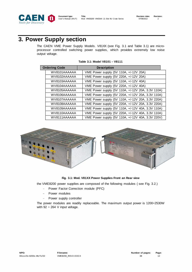
3. Power Supply section The CAEN VME Power Supply Models. V81XX (see Fig. 3.1 and Table 3.1) are micro-processor controlled switching power supplies, which provides extremely low noise output voltage.
Table 3.1: Model V8101 – V8111
Ordering Code Description WV8101AAAAAA VME Power supply (5V 110A, +/-12V 20A) WV8102AAAAAA VME Power supply (5V 220A, +/-12V 20A) WV8103AAAAAA VME Power supply (5V 110A, +/-12V 40A) WV8104AAAAAA VME Power supply (5V 220A, +/-12V 40A) WV8105AAAAAA VME Power supply (5V 110A, +/-12V 20A, 3.3V 110A) WV8106AAAAAA VME Power supply (5V 220A, +/-12V 20A, 3.3V 110A) WV8107AAAAAA VME Power supply (5V 110A, +/-12V 20A, 3.3V 220A) WV8108AAAAAA VME Power supply (5V 220A, +/-12V 20A, 3.3V 220A) WV8109AAAAAA VME Power supply (5V 110A, +/-12V 40A, 3.3V 110A) WV8110AAAAAA VME Power supply (5V 220A, +/-12V 40A, 3.3V 110A) WV8111AAAAAA VME Power supply (5V 110A, +/-12V 40A, 3.3V 220V)
Fig. 3.1: Mod. V81XX Power Supplies Front an Rear view
the VME8200 power supplies are composed of the following modules ( see Fig. 3.2.) - Power Factor Correction module (PFC) - Power modules - Power supply controller
The power modules are readily replaceable. The maximum output power is 1200÷2530W with 92 ÷ 264 V input voltage.

Document type: Title: Revision date: Revision: User's Manual (MUT) Mod. VME8200 VME64X 21 Slot 9U Crate Series 07/08/2013 2
NPO: Filename: Number of pages: Page: 00xxx/0x:8200x.MUTx/02 VME8200_REV2.DOCX 38 13
Table 3.2: Available Power Modules:
Type Vout Current (max) Power
Single / 2V ÷ 7V +(2V ÷ 7V) 115 A 550W
Twin / ±7V ÷ 16V +(7V ÷ 16V) 23 A 550W
-(7V ÷ 16V) 23 A 550W
Fig. 3.2: Mod. V81XX Power Supplies components
3.1 Power Connector section
Fig. 3.3: Mod. V81XX Power connector

Document type: Title: Revision date: Revision: User's Manual (MUT) Mod. VME8200 VME64X 21 Slot 9U Crate Series 07/08/2013 2
NPO: Filename: Number of pages: Page: 00xxx/0x:8200x.MUTx/02 VME8200_REV2.DOCX 38 14
Fig. 3.4: Mod. V81XX VME64X configuration
Table 3.3: Mod. V81XX Voltages and power modules configurations
Location Voltage Power Module Max Current V0 + 5 V 2V ÷ 7V 220 A V1 +12 V ±7V ÷ 16V 40 A V2 V3 + 3.3 V 2V ÷ 7V 220 A V4 V5 -12 ±7V ÷ 16V 40 A V6 V7 V8
3.2 VME8200 Power distribution
Table 3.4: Mod. VME8200 Max current per slot
Voltage Max Current per slot
+5V 10.5 A
+12V 1.9 A
-12V 1.9 A
+3.3V 5.2 A
3.3 Power Factor Correction Module (PFC) The mains input includes a Power Factor Correction Module (PFC) with main filters, soft start- circuit and fuses. If an external fuse or circuit breaker has to be installed, it shall have a capability of 16A. The AC input module is permanently powered after connecting the unit to the AC- mains. Switch ON/OFF activates only the DC on/off function of the power inverter modules. Turning on the power supply all voltages reach the nominal values nearly simultaneously within 50 ms whereby the voltage versus time curve shows a monotonic behavior. The start-off-time which corresponds to a value of 10% of the nominal voltages is reached
Document type: Title: Revision date: Revision: User's Manual (MUT) Mod. VME8200 VME64X 21 Slot 9U Crate Series 07/08/2013 2
NPO: Filename: Number of pages: Page: 00xxx/0x:8200x.MUTx/02 VME8200_REV2.DOCX 38 15
after 50 ms. The turn-on inrush current is limited by a soft start-circuit to a maximum value of 16 A. The power modules are readily replaceable. The maximum output power is 1200÷2530W with 92 ÷ 264 Vac input voltage.
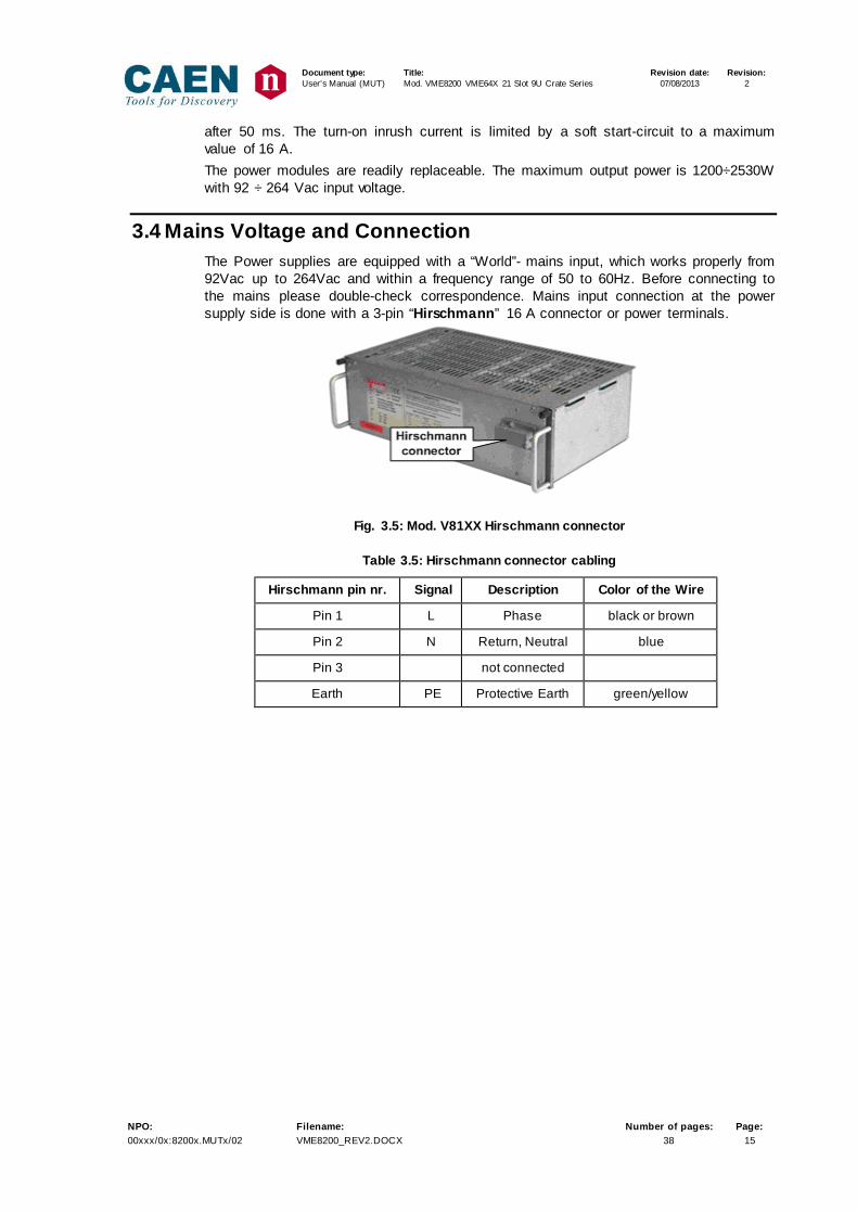
3.4 Mains Voltage and Connection The Power supplies are equipped with a “World”- mains input, which works properly from 92Vac up to 264Vac and within a frequency range of 50 to 60Hz. Before connecting to the mains please double-check correspondence. Mains input connection at the power supply side is done with a 3-pin “Hirschmann” 16 A connector or power terminals.
Fig. 3.5: Mod. V81XX Hirschmann connector
Table 3.5: Hirschmann connector cabling
Hirschmann pin nr. Signal Description Color of the Wire
Pin 1 L Phase black or brown
Pin 2 N Return, Neutral blue
Pin 3 not connected
Earth PE Protective Earth green/yellow

Document type: Title: Revision date: Revision: User's Manual (MUT) Mod. VME8200 VME64X 21 Slot 9U Crate Series 07/08/2013 2
NPO: Filename: Number of pages: Page: 00xxx/0x:8200x.MUTx/02 VME8200_REV2.DOCX 38 16
3.5 Power Supply specifications
3.5.1 Power Factor Correction Module
Table 3.6: Mod. VME8200 Power Factor Correction Module specifications
T
a
b
l
e
3.5.2 Power Modules The power modules are readily replaceable. Each module is equipped with temperature sensors for Over Temperature Protection.
Input Voltage Range 92 ÷ 264 Vac Frequency 50 ÷ 60 Hz
Inrush Current <16 A @ 230 Vac
Fuse External 16A type B/C
Power Factor > 0.98 @ Output Power > 1 kW
Output Maximum Total Output Power
1200 W @ 100 Vac 2530 W @ 211 Vac
Turn on Delay 50 ms to 100% of voltage, monotonic rise
Efficiency 75% ÷ 85% @ 230 Vac configuration dependent
Isolation CE EN 60950 Input to Output 3000 Vac
Input to GND 1500 Vac

Document type: Title: Revision date: Revision: User's Manual (MUT) Mod. VME8200 VME64X 21 Slot 9U Crate Series 07/08/2013 2
NPO: Filename: Number of pages: Page: 00xxx/0x:8200x.MUTx/02 VME8200_REV2.DOCX 38 17
Table 3.7: Mod. VME8200 Power Module (+5V +3.3V) technical specifications
Voltage 2V ÷ 7V
Current 115 A
Rise Time <50 ms to 100% of voltage, monotonic rise
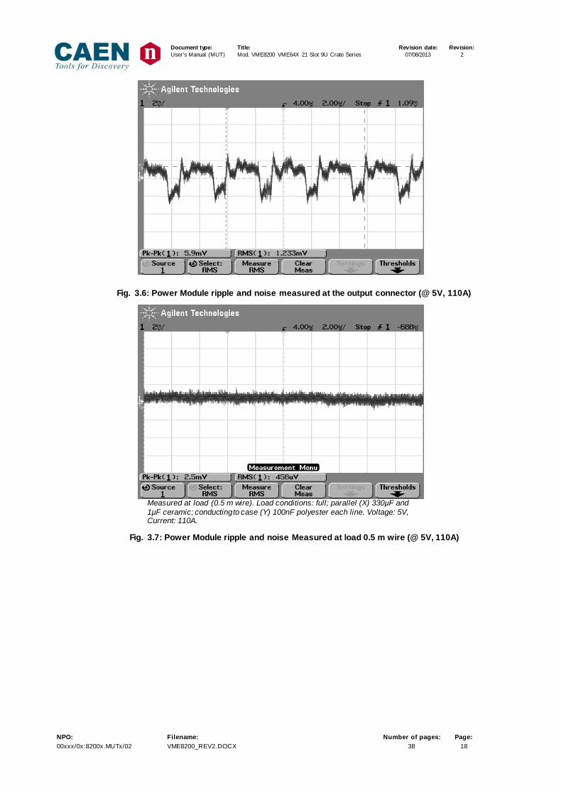
Ripple < 10 mVpp(1) Typ: 6.0 mVpp(1) (see Fig. 3.6) < 5 mVpp(2) Typ: 2.5 mVpp(2) (see Fig. 3.7)
Noise <2 mVrms(1) Typ: 1.5 mVrms(1) (see Fig. 3.6) <1.5 mVrms(2) Typ: 0.5 mVrms(2) (see Fig. 3.7)
Voltage Accuracy ± 20 mV
Minimum Load No
Load Regulation < 10 mV (sense) for 0-100% load change
Transient Response Recovery < 100 mV @ ±25A current step change 6 ms for recovery to ±1% of set voltage @ 25A to 0A current step change 0.5 ms for recovery to ± 1% of set voltage @ ±25A current step change 0.7 ms for recovery to ± 0.1% of set voltage @ ±25A current step change
Over Voltage Protection When the output voltage > 103% ÷ 120% (programmable) of set voltage
Under Voltage Protection When the output voltage < 80% ÷ 97% (programmable) of set voltage
Over Current Protection When the current > programmable Iset value
Short Circuit Protection <125 A @ 7 Vout
Over Temperature Protection When the Power module temperature > 90° C
flicker immunity < 50 ms
Environment Temperature 0° to 50° C Operational
Table 3.8: Mod. VME8200 Power Module (+12V -12V) technical specifications
Voltage ±7V ÷ ±16V
Current 23 A
Rise Time <50 ms to 100% of voltage, monotonic rise
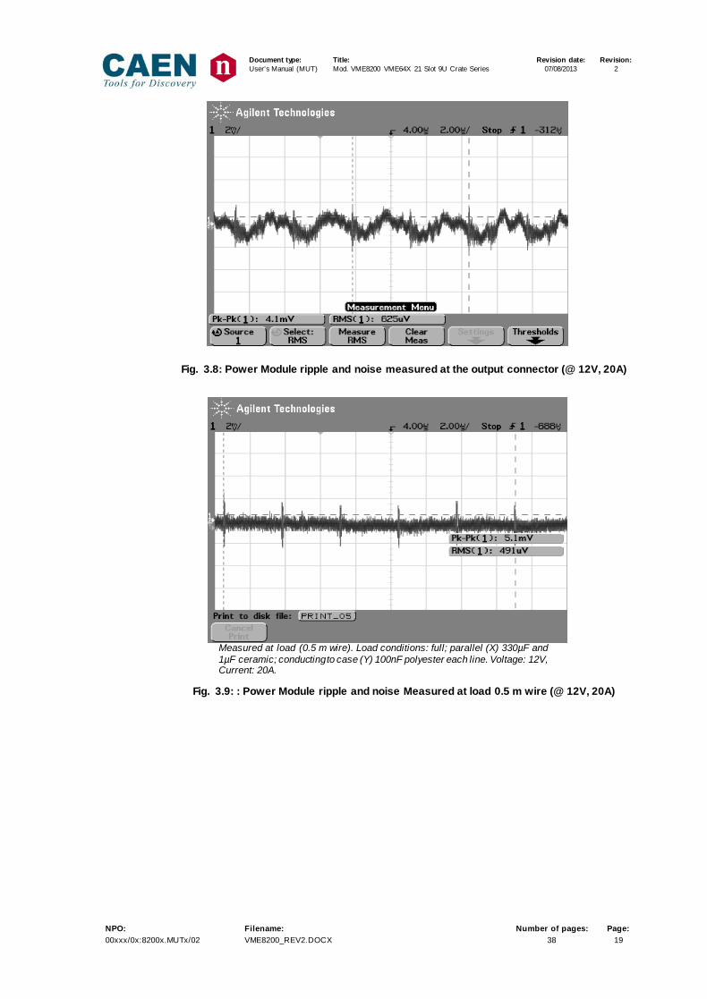
Ripple < 10 mVpp(1) Typ: 4.5 mVpp(1) (see Fig. 3.8) < 10 mVpp(2) Typ: 5.5 mVpp(2) (see Fig. 3.9)
Noise < 2 mVrms(1) Typ: 1.0 mVrms(1) (see Fig. 3.8) < 1.5 mVrms(2) Typ: 0.5 mVrms(2) (see Fig. 3.9)
Voltage Accuracy ± 20 mV
Minimum Load No
Load Regulation < 15 mV for 0-100% load change
Transient Response Recovery < 100 mV @ ±5A current step change 8 ms for recovery to ±1% of set voltage @ 5A to 0A current step change 1.0 ms for recovery to ± 1% of set voltage @ ±5A current step change 1.8 ms for recovery to ± 0.1% of set voltage @ ±5A current step change
Over Voltage Protection When the output voltage > 103% ÷ 120% (programmable) of set voltage
Under Voltge Protection When the output voltage < 80% ÷ 97% (programmable) of set voltage
Over Current Protection When the current > programmable Iset value
Short Circuit Protection < 26 A @ 16 Vout
Over Temperature Protection When the Power module temperature > 90° C
flicker immunity < 30 ms
Environment Temperature 0° to 50° C Operational (1) Measured at the Output connector (full load). (2) Measured at load (0.5 m w ire). Load conditions: full; parallel (X) 330µF and 1µF ceramic; conducting to case (Y) 100nF polyester each line.
Document type: Title: Revision date: Revision: User's Manual (MUT) Mod. VME8200 VME64X 21 Slot 9U Crate Series 07/08/2013 2
NPO: Filename: Number of pages: Page: 00xxx/0x:8200x.MUTx/02 VME8200_REV2.DOCX 38 18
Fig. 3.6: Power Module ripple and noise measured at the output connector (@ 5V, 110A)
Measured at load (0.5 m wire). Load conditions: full; parallel (X) 330µF and 1µF ceramic; conducting to case (Y) 100nF polyester each line. Voltage: 5V, Current: 110A.
Fig. 3.7: Power Module ripple and noise Measured at load 0.5 m wire (@ 5V, 110A)
Document type: Title: Revision date: Revision: User's Manual (MUT) Mod. VME8200 VME64X 21 Slot 9U Crate Series 07/08/2013 2
NPO: Filename: Number of pages: Page: 00xxx/0x:8200x.MUTx/02 VME8200_REV2.DOCX 38 19
Fig. 3.8: Power Module ripple and noise measured at the output connector (@ 12V, 20A)
Measured at load (0.5 m wire). Load conditions: full; parallel (X) 330µF and 1µF ceramic; conducting to case (Y) 100nF polyester each line. Voltage: 12V, Current: 20A.
Fig. 3.9: : Power Module ripple and noise Measured at load 0.5 m wire (@ 12V, 20A)
Document type: Title: Revision date: Revision: User's Manual (MUT) Mod. VME8200 VME64X 21 Slot 9U Crate Series 07/08/2013 2
NPO: Filename: Number of pages: Page: 00xxx/0x:8200x.MUTx/02 VME8200_REV2.DOCX 38 20
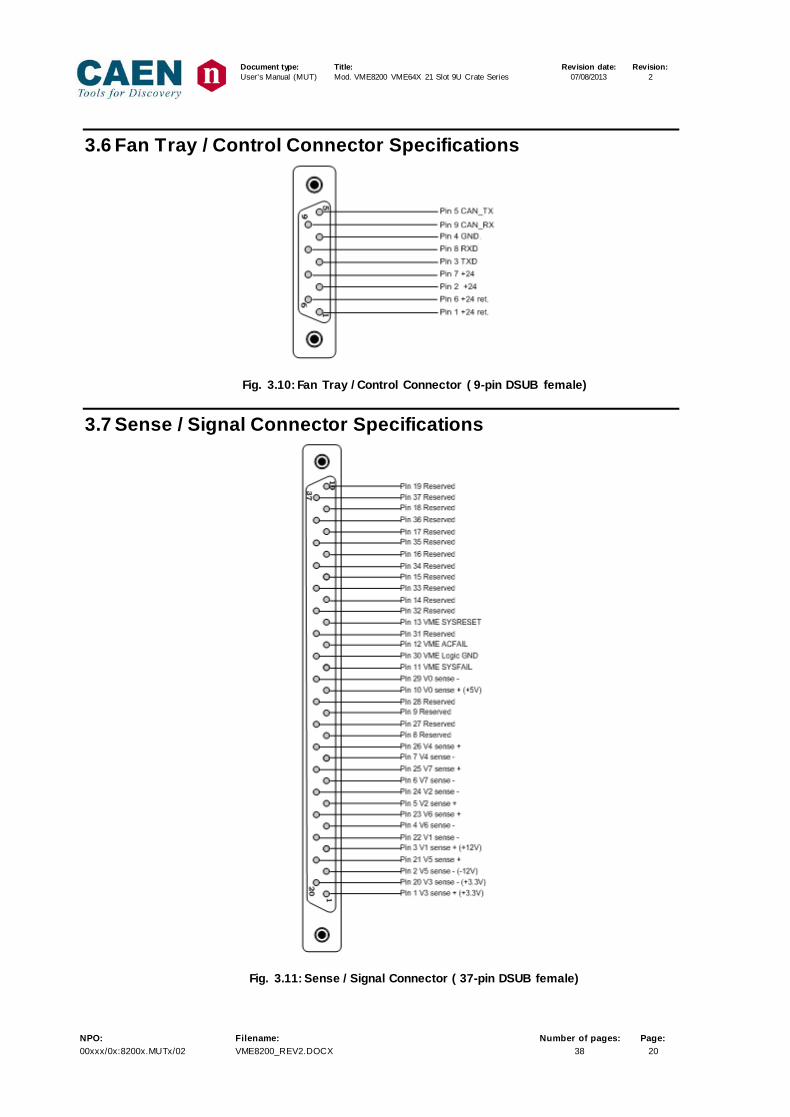
3.6 Fan Tray / Control Connector Specifications
Fig. 3.10: Fan Tray / Control Connector ( 9-pin DSUB female)
3.7 Sense / Signal Connector Specifications
Fig. 3.11: Sense / Signal Connector ( 37-pin DSUB female)
Document type: Title: Revision date: Revision: User's Manual (MUT) Mod. VME8200 VME64X 21 Slot 9U Crate Series 07/08/2013 2
NPO: Filename: Number of pages: Page: 00xxx/0x:8200x.MUTx/02 VME8200_REV2.DOCX 38 21
Document type: Title: Revision date: Revision: User's Manual (MUT) Mod. VME8200 VME64X 21 Slot 9U Crate Series 07/08/2013 2
NPO: Filename: Number of pages: Page: 00xxx/0x:8200x.MUTx/02 VME8200_REV2.DOCX 38 22
4. FAN Tray Section
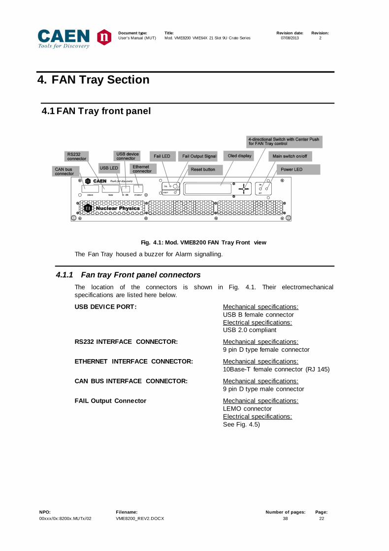
4.1 FAN Tray front panel
Fig. 4.1: Mod. VME8200 FAN Tray Front view
The Fan Tray housed a buzzer for Alarm signalling.
4.1.1 Fan tray Front panel connectors The location of the connectors is shown in Fig. 4.1. Their electromechanical specifications are listed here below.
USB DEVICE PORT: Mechanical specifications: USB B female connector Electrical specifications:
USB 2.0 compliant
RS232 INTERFACE CONNECTOR: Mechanical specifications: 9 pin D type female connector
ETHERNET INTERFACE CONNECTOR: Mechanical specifications: 10Base-T female connector (RJ 145)
CAN BUS INTERFACE CONNECTOR: Mechanical specifications: 9 pin D type male connector
FAIL Output Connector Mechanical specifications: LEMO connector Electrical specifications: See Fig. 4.5)

Document type: Title: Revision date: Revision: User's Manual (MUT) Mod. VME8200 VME64X 21 Slot 9U Crate Series 07/08/2013 2
NPO: Filename: Number of pages: Page: 00xxx/0x:8200x.MUTx/02 VME8200_REV2.DOCX 38 23
4.1.2 CAN bus connector Specifications CAN BUS interface features are as follows:
− CAN protocol 2.0B
− Transceiver PCA82C250
− 110 nodes at least guaranteed by the transceiver
− CAN connector 9-pin DSUB male
− TX/RX of standard frames with 11 bit identifier
Pinout of CAN bus connector is as follows:
Pin 5 N.C.Pin 9 N.C.Pin 4 N.C.Pin 8 N.C.Pin 3 GNDPin 7 CAN_HPin 2 CAN_LPin 6 N.C.Pin 1 N.C.
1
9
5
6
Fig. 4.2: CAN BUS connector
If the Bit Rate is higher than 100 Kbit/s it is necessary to terminate the CAN BUS line on 120 Ohm (inserted between CAN_H and CAN_L)
4.1.3 RS-232 Connector Specifications
6
1
9
5
Pin 1 N.C.Pin 6 N.C.Pin 2 TXPin 7 N.C.Pin 3 RXPin 8 N.C.Pin 4 N.C.Pin 9 N.C.Pin 5 GND
Fig. 4.3: RS-232 Connector (connector 9-pin DSUB female)

Document type: Title: Revision date: Revision: User's Manual (MUT) Mod. VME8200 VME64X 21 Slot 9U Crate Series 07/08/2013 2
NPO: Filename: Number of pages: Page: 00xxx/0x:8200x.MUTx/02 VME8200_REV2.DOCX 38 24
4.1.4 Ethernet LAN Connector Specifications
Fig. 4.4: Ethernet LAN Connector
Pin 1: TXD+ (Transmit Data +) Pin 2: TXD- (Transmit Data -) Pin 3: RXD+ (Receive Data +) Pin 4: EPWR+ (Power from switch +) Pin 5: EPWR+ (Power from switch +) Pin 6: RXD- (Receive Data -) Pin 7: EPWR- (Power from switch -) Pin 8: EPWR- (Power from switch -) Network Link LED: Yellow LED indicates network link is operational Netwowrk Activity LED: Green LED indicates network traffic detected
4.1.5 FAIL Connector Specifications
Fig. 4.5: FAIL output circuit
- Transistor model:: 2N3904 - max Current: 30 mA - stand by: pull-up 24V; - ALARM: 0.3V
GREEN YELLOW
1 8
Document type: Title: Revision date: Revision: User's Manual (MUT) Mod. VME8200 VME64X 21 Slot 9U Crate Series 07/08/2013 2
NPO: Filename: Number of pages: Page: 00xxx/0x:8200x.MUTx/02 VME8200_REV2.DOCX 38 25
2 secondNO FAIL
ALARM
1 second
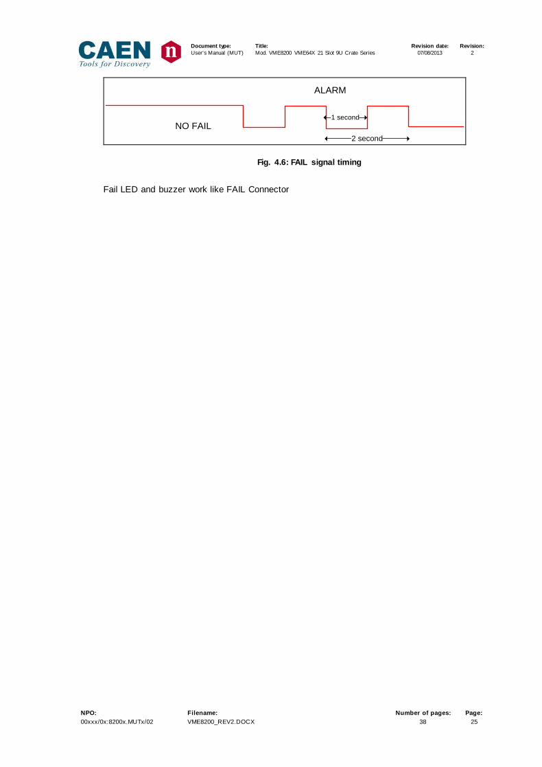
Fig. 4.6: FAIL signal timing
Fail LED and buzzer work like FAIL Connector
Document type: Title: Revision date: Revision: User's Manual (MUT) Mod. VME8200 VME64X 21 Slot 9U Crate Series 07/08/2013 2
NPO: Filename: Number of pages: Page: 00xxx/0x:8200x.MUTx/02 VME8200_REV2.DOCX 38 26
5. V8200 Operating
5.1 Turning ON/OFF In order to turn ON the crate, it is necessary to perform the following operations: − Check that the power supply module connectors are correctly inserted (see § 3.1) − Plug the power cord into the Vac mains power supply connector − As the CAEN logo fades, the power supply outputs can be turned On by keeping up
for a couple of seconds the on-off switch on the Fan Unit panel. − In order to turn OFF the crate, the switch must be kept down for a couple of seconds
as well.
5.2 Alarm and Trip off When the Crate Alarm is ON:
- FAIL LED lamps (timing described in Fig. 4.6) - FAIL Output signal is active (see § 4.1.5) - Buzzer is active (if enabled) - The Alarm reason is displayed on the FAN Unit OLED display end managed via
remote control The Crate DC voltages are tripped off and ALARM is ON in the case of:
- Over Voltage Protection: when the output voltage > 103% ÷ 120% (programmable) of set voltage (OVP parameter).
- Under Voltage Protection: when the output voltage < 80% ÷ 97% (programmable) of set voltage (UVP parameter)
- Over Current Protection: when the current > programmable Iset value - Over Temperature Protection: when temperature of a single Power module
> 90° C - AC FAIL: Problems On Power Factor Correction Module - VCC SUPPLY FAIL: problems on Power Supply Controller module or on power
Modules The Crate ALARM is ON in the case of:
- temperature FAN Unit > 50°C - temperature Power Supply Control module > 65° C - FAN fail - SYS Fail
5.3 FAN Tray Local programming The Crate can be controlled via various menu on the OLED display, which is enabled via: - Crate turning on via local switch - Crate turning on via remote interface
Document type: Title: Revision date: Revision: User's Manual (MUT) Mod. VME8200 VME64X 21 Slot 9U Crate Series 07/08/2013 2
NPO: Filename: Number of pages: Page: 00xxx/0x:8200x.MUTx/02 VME8200_REV2.DOCX 38 27
The display is disabled only via local switch crate off.
5.3.1 List of menu functions The following menu are available:
1. +5 V Monitor
• +5 V SET allows to set: Vset, Iset, UVP (% Vset), OVP (% Vset),
2. +12 V Monitor
• +12 V SET allows to set: Vset, Iset, UVP (% Vset), OVP (% Vset),
3. +3.3 V Monitor
• +3.3 V SET allows to set: Vset, Iset, UVP (% Vset), OVP (% Vset),
4. -12 V Monitor
• -12 V SET allows to set: Vset, Iset, UVP (% Vset), OVP (% Vset),
5. FAN Status
• SET FAN speed
6. ALARM
7. GENERAL
• Power Supply • VME • COMM
o RS 232 o CAN bus o ETHERNET
Document type: Title: Revision date: Revision: User's Manual (MUT) Mod. VME8200 VME64X 21 Slot 9U Crate Series 07/08/2013 2
NPO: Filename: Number of pages: Page: 00xxx/0x:8200x.MUTx/02 VME8200_REV2.DOCX 38 28
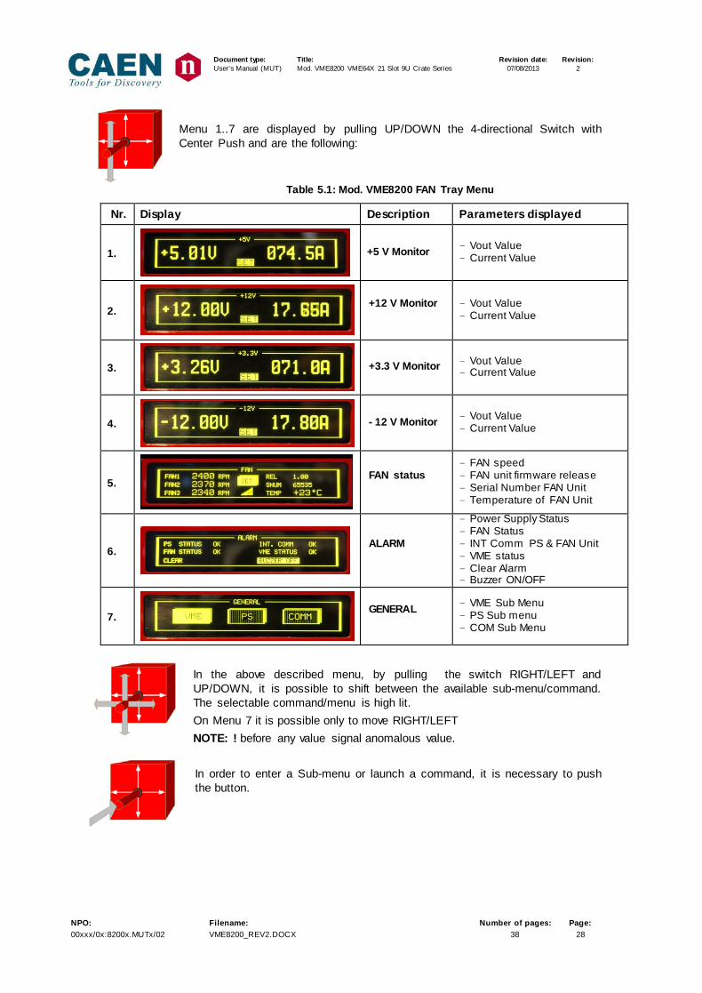
Menu 1..7 are displayed by pulling UP/DOWN the 4-directional Switch with Center Push and are the following:
Table 5.1: Mod. VME8200 FAN Tray Menu
Nr. Display Description Parameters displayed
1.
+5 V Monitor - Vout Value - Current Value
2.
+12 V Monitor
- Vout Value - Current Value
3.
+3.3 V Monitor - Vout Value - Current Value
4.
- 12 V Monitor - Vout Value - Current Value
5.
FAN status
- FAN speed - FAN unit firmware release - Serial Number FAN Unit - Temperature of FAN Unit
6.
ALARM
- Power Supply Status - FAN Status - INT Comm PS & FAN Unit - VME status - Clear Alarm - Buzzer ON/OFF
7.
GENERAL
- VME Sub Menu - PS Sub menu - COM Sub Menu
In the above described menu, by pulling the switch RIGHT/LEFT and UP/DOWN, it is possible to shift between the available sub-menu/command. The selectable command/menu is high lit. On Menu 7 it is possible only to move RIGHT/LEFT NOTE: ! before any value signal anomalous value. In order to enter a Sub-menu or launch a command, it is necessary to push the button.

Document type: Title: Revision date: Revision: User's Manual (MUT) Mod. VME8200 VME64X 21 Slot 9U Crate Series 07/08/2013 2
NPO: Filename: Number of pages: Page: 00xxx/0x:8200x.MUTx/02 VME8200_REV2.DOCX 38 29
Table 5.2: Mod. VME8200 FAN Tray Sub Menu
Nr. Display Description
8.
+5 V Set
9.
+12 V Set
10.
+3.3 V Set
11.
- 12 V Set
12.
FAN Set
13.
VME Status
14.
Power Supply Status
15.
Communication
16.
Communication RS232
17.
Communication CAN bus
18.
Communication Ethernet
Mac Address (show 5 sec)
19.
Communication Ethernet
status and set value
Document type: Title: Revision date: Revision: User's Manual (MUT) Mod. VME8200 VME64X 21 Slot 9U Crate Series 07/08/2013 2
NPO: Filename: Number of pages: Page: 00xxx/0x:8200x.MUTx/02 VME8200_REV2.DOCX 38 30
5.4 FAN Tray remote connection Connections available
- Ethernet connection via: o Program “VME8200 Manager” o Telnet (terminal emulator)
- RS232 via terminal - USB managed as RS232 requires driver for USB RS232 converter. (The Mod.
VME8200 FAN Tray control board housed a FT232BM chip which allows to manage the Mod. VME8120 FAN Tray via USB. Drivers for this device are freely available at: http://www.ftdichip.com/Drivers/VCP.htm)
NOTE: - RS232 and USB cannot be operated at the same time - Maximum of 3 Ethernet connection are allowed
5.4.1 Configure Ethernet connection On a Local Area Network with DHCP Server
In order to Obtain Configuration From Dynamic Host Configuration Protocol (DHCP) Server, the user must write Ethernet IP address = all 0 and reset the Crate. In this case, the server automatically assigns the IP address for the Crate VME8200.
Document type: Title: Revision date: Revision: User's Manual (MUT) Mod. VME8200 VME64X 21 Slot 9U Crate Series 07/08/2013 2
NPO: Filename: Number of pages: Page: 00xxx/0x:8200x.MUTx/02 VME8200_REV2.DOCX 38 31
6. Software overview
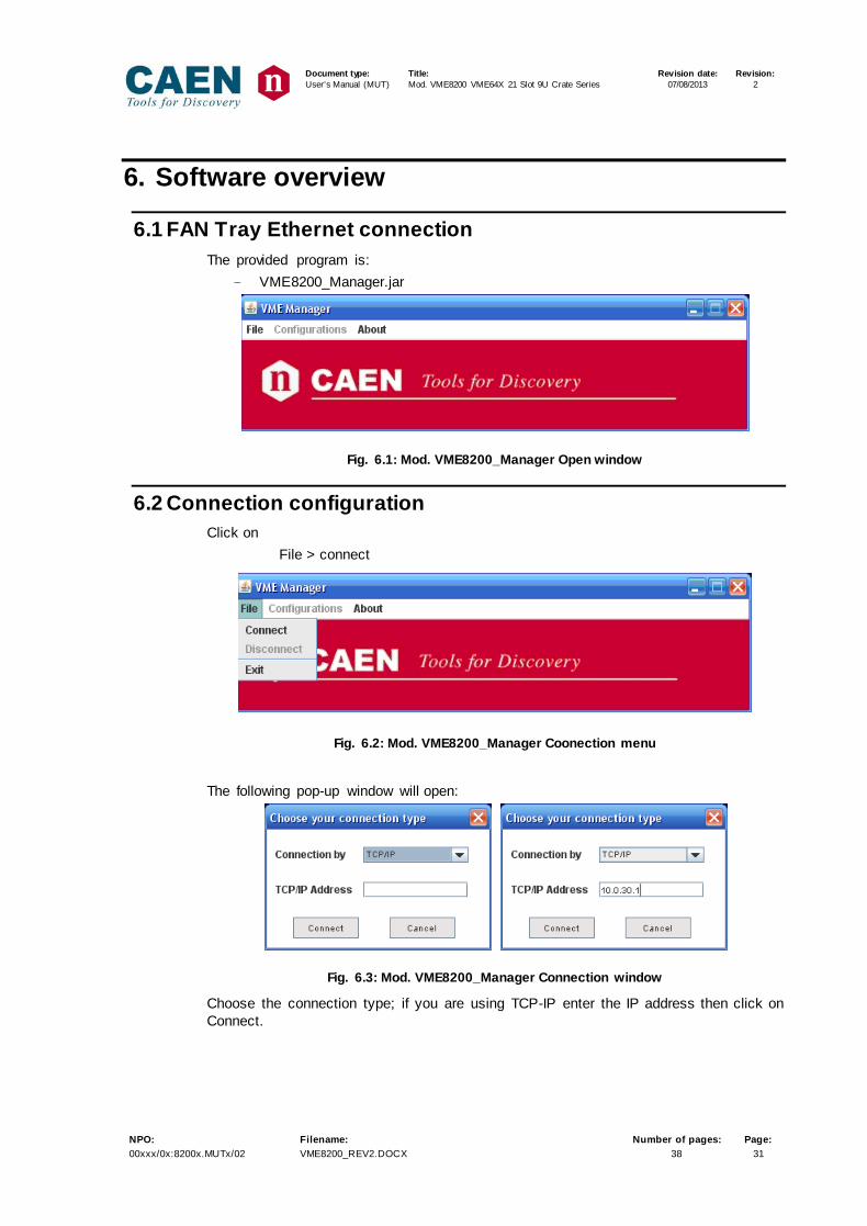
6.1 FAN Tray Ethernet connection The provided program is:
- VME8200_Manager.jar
Fig. 6.1: Mod. VME8200_Manager Open window
6.2 Connection configuration Click on
File > connect
Fig. 6.2: Mod. VME8200_Manager Coonection menu
The following pop-up window will open:
Fig. 6.3: Mod. VME8200_Manager Connection window
Choose the connection type; if you are using TCP-IP enter the IP address then click on Connect.
Document type: Title: Revision date: Revision: User's Manual (MUT) Mod. VME8200 VME64X 21 Slot 9U Crate Series 07/08/2013 2
NPO: Filename: Number of pages: Page: 00xxx/0x:8200x.MUTx/02 VME8200_REV2.DOCX 38 32
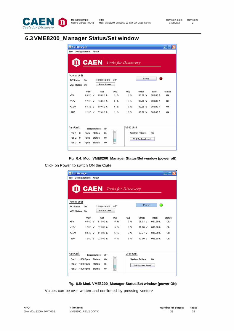
6.3 VME8200_Manager Status/Set window
Fig. 6.4: Mod. VME8200_Manager Status/Set window (power off)
Click on Power to switch ON the Crate
Fig. 6.5: Mod. VME8200_Manager Status/Set window (power ON)
Values can be over written and confirmed by pressing <enter>
Document type: Title: Revision date: Revision: User's Manual (MUT) Mod. VME8200 VME64X 21 Slot 9U Crate Series 07/08/2013 2
NPO: Filename: Number of pages: Page: 00xxx/0x:8200x.MUTx/02 VME8200_REV2.DOCX 38 33
6.3.1 VME8200_Manager VME System Reset operation Click on VME System Reset: the following window asks for confirmation:
6.4 FAN Tray RS232 /USB connection
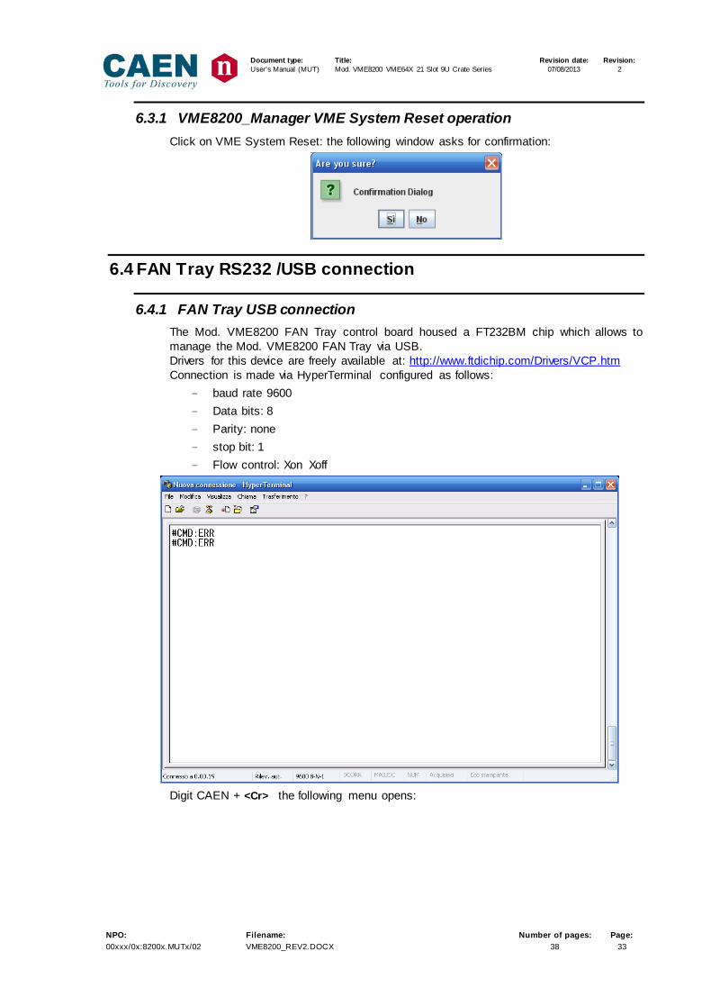
6.4.1 FAN Tray USB connection The Mod. VME8200 FAN Tray control board housed a FT232BM chip which allows to manage the Mod. VME8200 FAN Tray via USB. Drivers for this device are freely available at: http://www.ftdichip.com/Drivers/VCP.htm Connection is made via HyperTerminal configured as follows:
- baud rate 9600 - Data bits: 8 - Parity: none - stop bit: 1 - Flow control: Xon Xoff
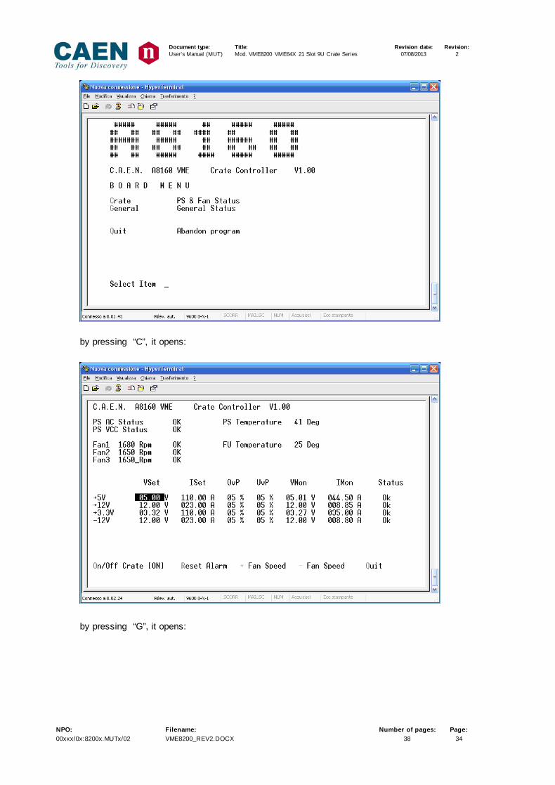
Digit CAEN + <Cr> the following menu opens:
Document type: Title: Revision date: Revision: User's Manual (MUT) Mod. VME8200 VME64X 21 Slot 9U Crate Series 07/08/2013 2
NPO: Filename: Number of pages: Page: 00xxx/0x:8200x.MUTx/02 VME8200_REV2.DOCX 38 34
by pressing “C”, it opens:
by pressing “G”, it opens:

Document type: Title: Revision date: Revision: User's Manual (MUT) Mod. VME8200 VME64X 21 Slot 9U Crate Series 07/08/2013 2
NPO: Filename: Number of pages: Page: 00xxx/0x:8200x.MUTx/02 VME8200_REV2.DOCX 38 35
Document type: Title: Revision date: Revision: User's Manual (MUT) Mod. VME8200 VME64X 21 Slot 9U Crate Series 07/08/2013 2
NPO: Filename: Number of pages: Page: 00xxx/0x:8200x.MUTx/02 VME8200_REV2.DOCX 38 36
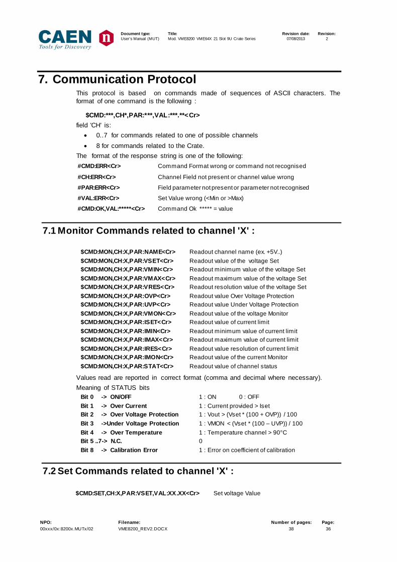
7. Communication Protocol This protocol is based on commands made of sequences of ASCII characters. The format of one command is the following :
$CMD:***,CH*,PAR:***,VAL:***.**<Cr> field 'CH' is:
• 0..7 for commands related to one of possible channels • 8 for commands related to the Crate.
The format of the response string is one of the following: #CMD:ERR<Cr> Command Format wrong or command not recognised
#CH:ERR<Cr> Channel Field not present or channel value wrong
#PAR:ERR<Cr> Field parameter not present or parameter not recognised
#VAL:ERR<Cr> Set Value wrong (<Min or >Max)
#CMD:OK,VAL:*****<Cr> Command Ok ***** = value
7.1 Monitor Commands related to channel 'X' :
$CMD:MON,CH:X,PAR:NAME<Cr> Readout channel name (ex. +5V..) $CMD:MON,CH:X,PAR:VSET<Cr> Readout value of the voltage Set $CMD:MON,CH:X,PAR:VMIN<Cr> Readout minimum value of the voltage Set $CMD:MON,CH:X,PAR:VMAX<Cr> Readout maximum value of the voltage Set $CMD:MON,CH:X,PAR:VRES<Cr> Readout resolution value of the voltage Set $CMD:MON,CH:X,PAR:OVP<Cr> Readout value Over Voltage Protection $CMD:MON,CH:X,PAR:UVP<Cr> Readout value Under Voltage Protection $CMD:MON,CH:X,PAR:VMON<Cr> Readout value of the voltage Monitor $CMD:MON,CH:X,PAR:ISET<Cr> Readout value of current limit $CMD:MON,CH:X,PAR:IMIN<Cr> Readout minimum value of current limit $CMD:MON,CH:X,PAR:IMAX<Cr> Readout maximum value of current limit $CMD:MON,CH:X,PAR:IRES<Cr> Readout value resolution of current limit $CMD:MON,CH:X,PAR:IMON<Cr> Readout value of the current Monitor $CMD:MON,CH:X,PAR:STAT<Cr> Readout value of channel status
Values read are reported in correct format (comma and decimal where necessary). Meaning of STATUS bits
Bit 0 -> ON/OFF 1 : ON 0 : OFF Bit 1 -> Over Current 1 : Current provided > Iset Bit 2 -> Over Voltage Protection 1 : Vout > (Vset * (100 + OVP)) / 100 Bit 3 ->Under Voltage Protection 1 : VMON < (Vset * (100 – UVP)) / 100 Bit 4 -> Over Temperature 1 : Temperature channel > 90°C Bit 5 ..7-> N.C. 0 Bit 8 -> Calibration Error 1 : Error on coefficient of calibration
7.2 Set Commands related to channel 'X' : $CMD:SET,CH:X,PAR:VSET,VAL:XX.XX<Cr> Set voltage Value
Document type: Title: Revision date: Revision: User's Manual (MUT) Mod. VME8200 VME64X 21 Slot 9U Crate Series 07/08/2013 2
NPO: Filename: Number of pages: Page: 00xxx/0x:8200x.MUTx/02 VME8200_REV2.DOCX 38 37
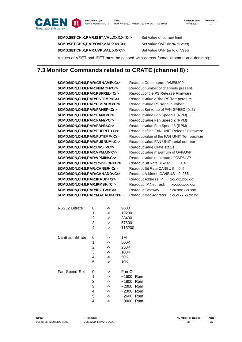
$CMD:SET,CH:X,PAR:ISET,VAL:XXX.X<Cr> Set Value of current limit
$CMD:SET,CH:X,PAR:OVP,VAL:XX<Cr> Set Value OVP (in % di Vset)
$CMD:SET,CH:X,PAR:UVP,VAL:XX<Cr> Set Value UVP (in % di Vset)
Values of VSET and ISET must be passed with correct format (comma and decimal).
7.3 Monitor Commands related to CRATE (channel 8) : $CMD:MON,CH:8,PAR:CRNAME<Cr> Readout Crate name : 'VME8200' $CMD:MON,CH:8,PAR:NUMCH<Cr> Readout number of channels present $CMD:MON,CH:8,PAR:PSFREL<Cr> Readout of the PS Release Firmware $CMD:MON,CH:8,PAR:PSTEMP<Cr> Readout value of the PS Temperature $CMD:MON,CH:8,PAR:PSSNUM<Cr> Readout value PS serial number $CMD:MON,CH:8,PAR:FANSP<Cr> Readout Set value of FAN SPEED (0..6) $CMD:MON,CH:8,PAR:FAN1<Cr> Readout value Fan Speed 1 (RPM) $CMD:MON,CH:8,PAR:FAN2<Cr> Readout value Fan Speed 2 (RPM) $CMD:MON,CH:8,PAR:FAN3<Cr> Readout value Fan Speed 3 (RPM) $CMD:MON,CH:8,PAR:FUFREL<Cr> Readout of the FAN UNIT Release Firmware $CMD:MON,CH:8,PAR:FUTEMP<Cr> Readout value of the FAN UNIT Temperature $CMD:MON,CH:8,PAR:FUSNUM<Cr> Readout value FAN UNIT serial number $CMD:MON,CH:8,PAR:CRST<Cr> Readout value Crate status $CMD:MON,CH:8,PAR:VPMAX<Cr> Readout value maximum of OVP/UVP $CMD:MON,CH:8,PAR:VPMIN<Cr> Readout value minimum of OVP/UVP $CMD:MON,CH:8,PAR:RS232BR<Cr> Readout Bit Rate RS232 : 0..4 $CMD:MON,CH:8,PAR:CANBR<Cr> Readout Bit Rate CANBUS : 0..5 $CMD:MON,CH:8,PAR:CANADD<Cr> Readout Address CANBUS : 0..255 $CMD:MON,CH:8,PAR:IPADD<Cr> Readout Address IP : xxx.xxx.xxx.xxx $CMD:MON,CH:8,PAR:IPMSK<Cr> Readout IP Netmask : xxx.xxx.xxx.xxx $CMD:MON,CH:8,PAR:IPGTW<Cr> Readout Gateway : xxx.xxx.xxx.xxx $CMD:MON,CH:8,PAR:MACADD<Cr> Readout Mac Address : xx.xx.xx.xx.xx.xx
RS232 Bitrate : 0 -> 9600 1 -> 19200 2 -> 38400 3 -> 57600 4 -> 115200 CanBus Bitrate : 0 -> 1M 1 -> 500K 2 -> 250K 3 -> 100K 4 -> 50K 5 -> 10K Fan Speed Set : 0 -> Fan Off 1 -> ~1500 Rpm 2 -> ~1800 Rpm 3 -> ~2000 Rpm 4 -> ~2300 Rpm 5 -> ~2600 Rpm 4 -> ~3000 Rpm
Document type: Title: Revision date: Revision: User's Manual (MUT) Mod. VME8200 VME64X 21 Slot 9U Crate Series 07/08/2013 2
NPO: Filename: Number of pages: Page: 00xxx/0x:8200x.MUTx/02 VME8200_REV2.DOCX 38 38
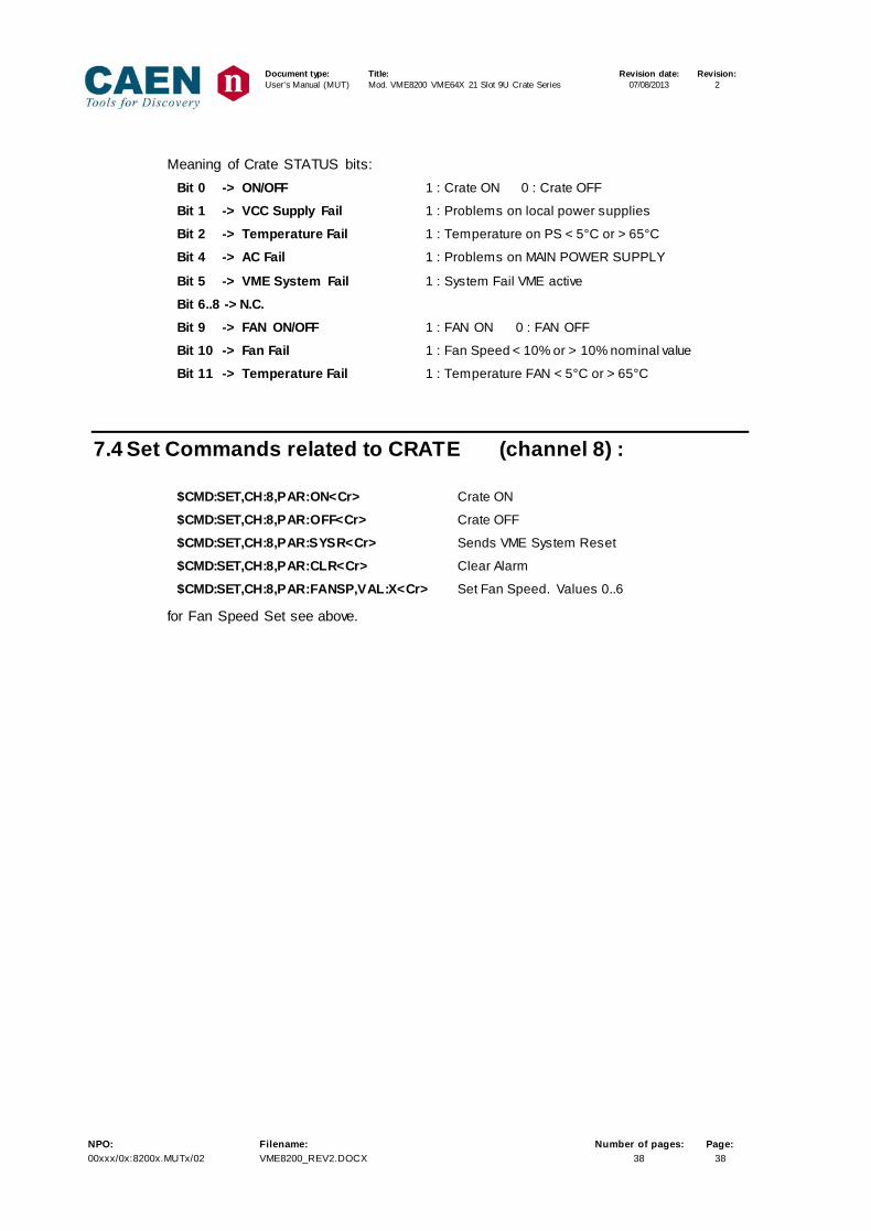
Meaning of Crate STATUS bits:
Bit 0 -> ON/OFF 1 : Crate ON 0 : Crate OFF
Bit 1 -> VCC Supply Fail 1 : Problems on local power supplies
Bit 2 -> Temperature Fail 1 : Temperature on PS < 5°C or > 65°C
Bit 4 -> AC Fail 1 : Problems on MAIN POWER SUPPLY
Bit 5 -> VME System Fail 1 : System Fail VME active
Bit 6..8 -> N.C.
Bit 9 -> FAN ON/OFF 1 : FAN ON 0 : FAN OFF
Bit 10 -> Fan Fail 1 : Fan Speed < 10% or > 10% nominal value
Bit 11 -> Temperature Fail 1 : Temperature FAN < 5°C or > 65°C
7.4 Set Commands related to CRATE (channel 8) :
$CMD:SET,CH:8,PAR:ON<Cr> Crate ON
$CMD:SET,CH:8,PAR:OFF<Cr> Crate OFF
$CMD:SET,CH:8,PAR:SYSR<Cr> Sends VME System Reset
$CMD:SET,CH:8,PAR:CLR<Cr> Clear Alarm
$CMD:SET,CH:8,PAR:FANSP,VAL:X<Cr> Set Fan Speed. Values 0..6
for Fan Speed Set see above.