technical instructions for safety recall csj rear …
TRANSCRIPT

TECHNICAL INSTRUCTIONS
FOR
SAFETY RECALL CSJ
REAR LOWER SUSPENSION ARM No.1
2006 – EARLY 2011 MODEL YEAR RAV4
Complete CSJ Technical Video Supplement
ONLY TECHNICIANS WHO HAVE COMPLETED TRAINING COURSES SC13A, SC13C, AND HAVE THE FOLLOWING LEVEL OF CERTIFICATION CAN PERFORM THIS REPAIR: • CHASSIS EXPERT TECHNICIANS • MASTER TECHNICIANS • MASTER DIAGNOSTIC TECHNICIANS
As of 8/27/13 the Remedy instructions are only applicable to the following regions: Boston
Refer to the Dealer Letter for anticipated remedy dates for all remaining regions

I. OPERATION FLOW CHART
Campaign complete, return the vehicle to the customer.
Inspect the threads under the adjusting tube and lock nuts for rust.
Rust
Verify Vehicle Eligibility1. Check the VIN range.
2. Check the TIS Vehicle Inquiry System.
No further action required.Not Covered
Covered
Inspect visually and by hand for looseness.
NOT Loose
The lock nut tightening procedure is critical. Follow the steps EXACTLY as
described in these instructions.
Loose
Perform four wheel alignment. Tighten suspension arm lock nuts correctly.
Check the suspension arm No.1 design.
Adjusting cam designONLY a small number of vehicles
with have the adjusting cam design
Adjusting tube design
Replace the suspension arm.
Apply epoxy and labels to the suspension arms.
NO Rust
II. BACKGROUND
Video supplement: Introduction
Safety Recall C0J involved inspecting the right and left Rear Suspension Lower Arm No. 1 (“arm”) for looseness. Based upon this inspection, it may have been necessary to replace the arm(s).
TMS received reports from dealers indicating that some vehicles experienced symptoms of the recalled condition after being inspected or repaired. Upon investigation, it was discovered that some inspections were not adequate and portions of the repair procedure may not have been performed correctly.
Based upon this information, Toyota will be re-notifying all owners covered by Safety Recall C0J. The notification will apologize to customers and inform them that their vehicles may not have been inspected or repaired correctly. The letter will request the customer to return to the dealership for a revised inspection and remedy procedure. The revised inspection and remedy will be performed at No Charge.
2

III. PREPARATION
A. PARTS
Part Number Part Description Quantity 00289-SW1KT-DS Epoxy Kit 1
*The kit above includes the following parts.
− 50ml Epoxy Cartridge 1 − Mixing Nozzle 1 − Caution Labels 2
All vehicles will require this epoxy kit.
Part Number Part Description Quantity 04002-22142 Rear Suspension Arm No.1 Kit* 1
*The kit above includes the following parts.
48710-0R010 Rear Lower Suspension Arm No.1 1 90179-12027 Nut 1
This part will be replaced based upon inspection, follow these instructions for details.
B. TOOLS & EQUIPMENT
• Standard hand tools • Torque wrench • 22mm crowfoot • 4 Wheel alignment machine
C. MATERIALS • FIPG 00295-00103 – Needed if voids are found in the epoxy, follow these instructions for details • Frekote Lifft Mold Release 00289-HKLMR-DS – This material is only currently available in case quantity
(12 cans/case), one can will cover approximately 75 vehicles
SST – This is an essential special service tool that the dealership should have. Part Number Part Name Quantity 09960-20010 Ball Joint Puller Set 1
CAMPAIGN TOOLS – These tools are provided to the dealership. These tools are necessary when performing this repair.
Image Name Quantity
Epoxy Mold Set 4 halves / 2 complete molds
Epoxy Applicator 1
NOTE: These tools CANNOT be ordered through the parts or tools system. There is a very limited supply of tools, but if additional tools are needed, contact your regional representative.
3

IV. IDENTIFICATION OF AFFECTED VEHICLES
A. COVERED VIN RANGE
WMI Year VDS Range WMI Year VDS Range VDS Range VDS Range
2T3 2009 BF31V W001119-W024119 2T3 2011 ZF4DV W052609-W052873 2T3 2009 BF32V W001207-W024120 2T3 2011 ZK4DV W008870-W008870 2T3 2009 BF33V W001117-W024117 JTM 2006 BD31V 5000052-6022606 2T3 2009 BF34V W003775-W021681 JTM 2006 BD32V 5000029-6022607 2T3 2009 BF35V W001421-W024111 JTM 2006 BD33V 5000087-6022596 2T3 2009 BK31V W001143-W013774 JTM 2006 BD34V 5000058-5051164 2T3 2009 BK32V W001142-W013693 JTM 2006 BD35V 5000031-5051248 2T3 2009 BK33V W001162-W013773 JTM 2006 BK31V 5000008-6010002 2T3 2009 BK34V W001688-W010762 JTM 2006 BK32V 5000011-6010006 2T3 2009 BK35V W002139-W013749 JTM 2006 BK33V 5000022-6009992 2T3 2009 ZF31V W001050-W016880 JTM 2006 BK34V 5000028-5012673 2T3 2009 ZF32V W001048-W016874 JTM 2006 BK35V 5000010-5012694 2T3 2009 ZF33V W001049-W016918 JTM 2006 ZD31V 5000027-6020783 2T3 2009 ZF34V W003810-W012950 JTM 2006 ZD32V 5000006-6020798 2T3 2009 ZF35V W001625-W016916 JTM 2006 ZD33V 5000019-6020842 2T3 2009 ZK31V W001081-W003645 JTM 2006 ZD34V 5000025-5032507 2T3 2009 ZK32V W001149-W003642 JTM 2006 ZD35V 5000005-5032573 2T3 2009 ZK33V W001076-W003644 JTM 2006 ZK31V 5000007-6003129 2T3 2009 ZK34V W001670-W002621 JTM 2006 ZK32V 5000005-6003131 2T3 2009 ZK35V W001965-W003631 JTM 2006 ZK33V 5000011-6003132 2T3 2010 BF4DV W022899-W082387 JTM 2006 ZK34V 5000004-5005681 2T3 2010 BK4DV W013775-W036881 JTM 2006 ZK35V 5000060-5005684 2T3 2010 DF4DV W024130-W082385 JTM 2007 BD31V 5051303-6054728 2T3 2010 DK4DV W013776-W036900 JTM 2007 BD32V 5051315-6054737 2T3 2010 EF4DV W024745-W069582 JTM 2007 BD33V 5051301-6054736 2T3 2010 EK4DV W014634-W036700 JTM 2007 BD34V 5052182-5124068 2T3 2010 JF4DV W024129-W082307 JTM 2007 BD35V 5051278-5124278 2T3 2010 JK4DV W013811-W036888 JTM 2007 BK31V 5012706-6028074 2T3 2010 KF4DV W016950-W052601 JTM 2007 BK32V 5012016-6028066 2T3 2010 KK4DV W003824-W008864 JTM 2007 BK33V 5012697-6028069 2T3 2010 RF4DV W022777-W082383 JTM 2007 BK34V 5012752-5040742 2T3 2010 RK4DV W013813-W036821 JTM 2007 BK35V 5012701-5040698 2T3 2010 WF4DV W016936-W052514 JTM 2007 ZD31V 5031315-6052970 2T3 2010 WK4DV W003659-W008863 JTM 2007 ZD32V 5031131-6052984 2T3 2010 XF4DV W018112-W052094 JTM 2007 ZD33V 5032593-6052993 2T3 2010 XK4DV W003701-W006779 JTM 2007 ZD34V 5032641-5077858 2T3 2010 YF4DV W016920-W052604 JTM 2007 ZD35V 5032630-5077997 2T3 2010 YK4DV W003435-W008860 JTM 2007 ZK31V 5005691-6010016 2T3 2010 ZF4DV W016923-W052607 JTM 2007 ZK32V 5005392-6010013 2T3 2010 ZK4DV W003652-W008861 JTM 2007 ZK33V 5005699-6010017 2T3 2011 BF4DV W077612-W082793 JTM 2007 ZK34V 5005692-5016122 2T3 2011 BK4DV W036909-W037018 JTM 2007 ZK35V 5005728-5016021 2T3 2011 DF4DV W082411-W082788 JTM 2008 BD31V 5122515-6089730 2T3 2011 DK4DV W036901-W037033 JTM 2008 BD32V 5124567-6089718 2T3 2011 JF4DV W082409-W082756 JTM 2008 BD33V 5124318-6089729 2T3 2011 JK4DV W037020-W037025 JTM 2008 BD34V 5124315-5215683 2T3 2011 KF4DV W052688-W052839 JTM 2008 BD35V 5124310-5215906 2T3 2011 RF4DV W082407-W082781 JTM 2008 BK31V 5040755-6050078 2T3 2011 RK4DV W036971-W036988 JTM 2008 BK32V 5039902-6050082 2T3 2011 WF4DV W050399-W052858 JTM 2008 BK33V 5040768-6050066 2T3 2011 WK4DV W008866-W008877 JTM 2008 BK34V 5040763-5071435 2T3 2011 YF4DV W052611-W052872 JTM 2008 BK35V 5040804-5071479 2T3 2011 YK4DV W008867-W008880 JTM 2008 ZD31V 5078027-6081056
4
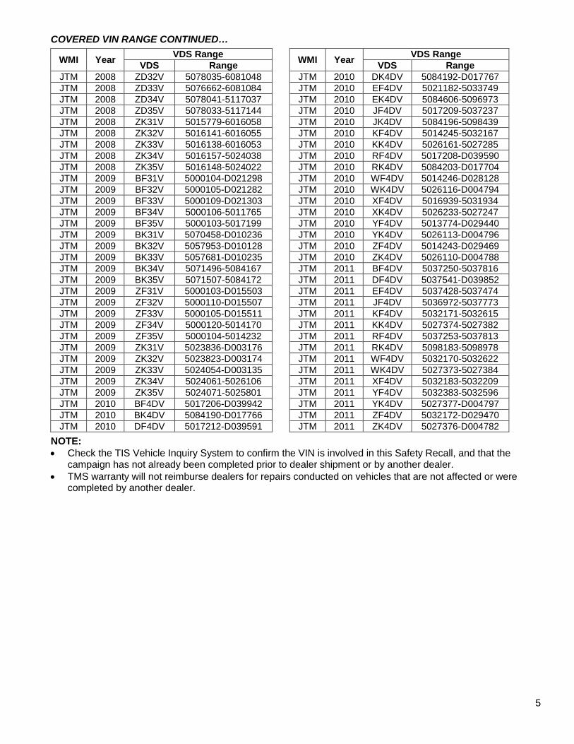
COVERED VIN RANGE CONTINUED…
WMI Year VDS Range WMI Year VDS Range VDS Range VDS Range
JTM 2008 ZD32V 5078035-6081048 JTM 2010 DK4DV 5084192-D017767 JTM 2008 ZD33V 5076662-6081084 JTM 2010 EF4DV 5021182-5033749 JTM 2008 ZD34V 5078041-5117037 JTM 2010 EK4DV 5084606-5096973 JTM 2008 ZD35V 5078033-5117144 JTM 2010 JF4DV 5017209-5037237 JTM 2008 ZK31V 5015779-6016058 JTM 2010 JK4DV 5084196-5098439 JTM 2008 ZK32V 5016141-6016055 JTM 2010 KF4DV 5014245-5032167 JTM 2008 ZK33V 5016138-6016053 JTM 2010 KK4DV 5026161-5027285 JTM 2008 ZK34V 5016157-5024038 JTM 2010 RF4DV 5017208-D039590 JTM 2008 ZK35V 5016148-5024022 JTM 2010 RK4DV 5084203-D017704 JTM 2009 BF31V 5000104-D021298 JTM 2010 WF4DV 5014246-D028128 JTM 2009 BF32V 5000105-D021282 JTM 2010 WK4DV 5026116-D004794 JTM 2009 BF33V 5000109-D021303 JTM 2010 XF4DV 5016939-5031934 JTM 2009 BF34V 5000106-5011765 JTM 2010 XK4DV 5026233-5027247 JTM 2009 BF35V 5000103-5017199 JTM 2010 YF4DV 5013774-D029440 JTM 2009 BK31V 5070458-D010236 JTM 2010 YK4DV 5026113-D004796 JTM 2009 BK32V 5057953-D010128 JTM 2010 ZF4DV 5014243-D029469 JTM 2009 BK33V 5057681-D010235 JTM 2010 ZK4DV 5026110-D004788 JTM 2009 BK34V 5071496-5084167 JTM 2011 BF4DV 5037250-5037816 JTM 2009 BK35V 5071507-5084172 JTM 2011 DF4DV 5037541-D039852 JTM 2009 ZF31V 5000103-D015503 JTM 2011 EF4DV 5037428-5037474 JTM 2009 ZF32V 5000110-D015507 JTM 2011 JF4DV 5036972-5037773 JTM 2009 ZF33V 5000105-D015511 JTM 2011 KF4DV 5032171-5032615 JTM 2009 ZF34V 5000120-5014170 JTM 2011 KK4DV 5027374-5027382 JTM 2009 ZF35V 5000104-5014232 JTM 2011 RF4DV 5037253-5037813 JTM 2009 ZK31V 5023836-D003176 JTM 2011 RK4DV 5098183-5098978 JTM 2009 ZK32V 5023823-D003174 JTM 2011 WF4DV 5032170-5032622 JTM 2009 ZK33V 5024054-D003135 JTM 2011 WK4DV 5027373-5027384 JTM 2009 ZK34V 5024061-5026106 JTM 2011 XF4DV 5032183-5032209 JTM 2009 ZK35V 5024071-5025801 JTM 2011 YF4DV 5032383-5032596 JTM 2010 BF4DV 5017206-D039942 JTM 2011 YK4DV 5027377-D004797 JTM 2010 BK4DV 5084190-D017766 JTM 2011 ZF4DV 5032172-D029470 JTM 2010 DF4DV 5017212-D039591 JTM 2011 ZK4DV 5027376-D004782
NOTE: • Check the TIS Vehicle Inquiry System to confirm the VIN is involved in this Safety Recall, and that the
campaign has not already been completed prior to dealer shipment or by another dealer. • TMS warranty will not reimburse dealers for repairs conducted on vehicles that are not affected or were
completed by another dealer.
5

V. COMPONENTS
VI. REAR LOWER SUSPENSION ARM No.1 INSPECTION
1. CHECK THE SUSPENSION ARM DESIGN
ADJUSTING TUBE DESIGN ADJUSTING CAM DESIGN
ARM DESIGN ACTION REQUIRED Adjusting Tube Proceed to STEP 2. CHECK FOR LOOSENESS VISUALLY AND BY HAND Adjusting Cam No further action required. Campaign complete.
6

• Replace the suspension arm(s) if: • Looseness is found. • A gap is visible between the lock nut(s) and adjusting tube.
• The arm(s) that do not exhibit the above conditions MUST also be inspected for rust.
Video supplement: Suspension Arm Inspection steps
2. CHECK FOR LOOSENESS VISUALLY AND BY HAND
a) Check visually and by hand to determine if any looseness is seen or felt in the suspension arm lock nuts or adjusting tube. Check the LH and RH arms.
NOTE: If recall C0J was previously performed and suspension arm clips are installed, remove and discard the clips.
b) Inspect for a gap between the lock nuts and the adjusting tube.
CONDITION ACTION REQUIRED
Loose OR Gap
Replace the suspension arm(s) with looseness OR if a gap is found between the lock nut(s) and adjusting tube. Refer to TIS for instructions on suspension arm replacement. NOTE: • To prevent stress on the new suspension arm bushing, apply a load to the
suspension system to confirm the suspension arm bushing is aligned correctly when tightening by confirming that rear suspension arm No.1 is level with the ground.
• Suspension arm adjustment and tightening procedure is critical. After replacing the arm, refer to SECTION VII. in these instructions for this procedure.
NOT Loose AND
NO Gap Proceed to STEP 3. CHECK THE SUSPENSION ARM THREADS FOR RUST
7

3. CHECK THE SUSPENSION ARM THREADS FOR RUST
a) Brush the exposed threads if there is excessive buildup or rust on the threads.
NOTE: Brushing the threads will ease the loosening of the nuts.
b) Hold the adjusting tube steady and loosen each lock nut to expose 1/8” (3mm) of threads.
NOTE: It takes approximately 2 complete revolutions of the nut to expose 1/8” of threads
If either nut is seized or extremely tight, the arm should be replaced. DO NOT apply heat in an attempt to loosen the arm.
c) Rotate the adjusting tube to expose an additional 3/8” (10mm) of threads.
NOTE: To prevent the arm from binding when rotating, hold the ball joint side with locking pliers.
If the adjusting tube is seized or extremely tight, the arm should be replaced. DO NOT apply heat in an attempt to loosen the arm.
There should now be 1/2” (12mm) of threads exposed on both sides of the adjusting tube.
8

d) Use a flashlight to inspect the newly exposed threads for RED RUST.
In order to perform a thorough inspection, it is CRITICAL to use a flashlight when inspecting for rust.
CONDITION ACTION REQUIRED Obvious red rust
Replace the suspension arm(s) that exhibit any of the three conditions to the left. Refer to TIS for instructions on suspension arm replacement. NOTE: • To prevent stress on the new suspension
arm bushing, apply a load to the suspension system to confirm the suspension arm bushing is aligned correctly when tightening by confirming that rear suspension arm No.1 is level with the ground.
• Suspension arm adjustment and tightening procedure is critical. After replacing the arm, refer to SECTION VII. in these instructions for this procedure.
Small amount of red rust
Red rust and white residue
INSPECTION CONDITIONS CONTINUED ON NEXT PAGE
9

d) Inspection conditions continued.
In order to perform a thorough inspection, it is CRITICAL to use a flashlight when inspecting for rust.
CONDITION ACTION REQUIRED White residue ONLY
Temporarily tighten the arm back to the original condition. Confirm the inspection is performed on both arms then proceed to vehicle alignment. NOTE: Suspension arm adjustment and tightening procedure is critical. Refer to SECTION VII. in these instructions for this procedure.
NO Red Rust and NO White Residue
10

VII. SUSPENSION ARM ADJUSTMENT AND LOCK NUT TIGHTENING
Video Supplement: Suspension Arm Adjustment and Lock Nut Tightening steps
1. JOUNCE THE REAR OF THE VEHICLE
a) Due to the pressure applied to the rear suspension system during inspection, it is CRITICAL to jounce the rear of the vehicle to resettle the suspension prior to vehicle alignment.
2. PERFORM FOUR WHEEL ALIGNMENT
a) Perform alignment using an alignment machine.
b) Test drive the vehicle to confirm the alignment.
• Holding the adjusting steady tube is CRITICAL when tightening the lock nuts, if the adjusting tube is not held steady the lock nuts may become loose.
• The alignment MUST be performed by the same technician performing the recall. Only one person should perform the entire recall on each vehicle.
• The tightening procedure for these lock nuts is critical, failure to tighten them in the correct order could cause them to become loose.
VITAL STEPS
3. TIGHTEN THE LOCK NUTS EXACTLY AS DESCRIBED BELOW
Use a 22mm combination wrench and a 22mm crowfoot attached to a torque wrench Tightening Sequence: 1. Inboard 2. Outboard 3. Inboard Again Torque: 41ft. lbf (56N∙m)
a) Tighten the inboard lock nut. Hold the adjusting tube steady and tighten the inboard lock nut to the specified torque.
b) Tighten the outboard lock nut. Hold the adjusting tube steady and tighten the outboard lock nut to the specified torque.
c) Tighten the inboard lock nut again. Hold the adjusting tube steady and tighten the inboard lock nut to the specified torque.
11

VIII. SUSPENSION ARM EPOXY APPLICATION
Video Supplement: Epoxy Application steps
Confirm the thread inspection, vehicle alignment, and lock nut tightening have all been performed correctly before proceeding.
1. PREPARE THE EPOXY MOLDS
a) Confirm there is no dried epoxy or debris in the molds.
b) Apply two light coats of the mold release to the molds.
c) Once the mold release has dried, there should not be wet pools in the molds.
NOTE: The mold release will set and be ready for epoxy application after 60 seconds.
2. CLEAN THE SUSPENSION ARM
a) Clean the area of the arm where the epoxy will be applied.
b) Use a steel bristle brush to remove any rust buildup and flaking that may be present on the arm.
c) Use a rag and brake clean to finish cleaning the arm.
Cleaning the exterior surface, even on a new arm, is CRITICAL to confirm the epoxy adheres properly.
3. FILL THE MOLDS WITH EPOXY
a) Assemble the applicator by following the instructions included in the applicator box.
b) Install the epoxy cartridge in the applicator.
c) Install the mixing nozzle to the cartridge.
d) Start by squeezing the handle to pre-fill the mixing tube until the epoxy reaches the end of the nozzle, then stop squeezing.
Pre-filling the mixing nozzle is critical to ensure the molds are each filled with even amounts of epoxy in the following steps.
NOTE: Confirm the one-to-one ratio plunger is installed in the applicator.
12

4. FILL THE MOLDS WITH EPOXY
• One complete epoxy cartridge should be used for every 2 suspension arms. • There are approximately 12 full squeezes of epoxy in each cartridge. • Follow these steps exactly as described so there are no voids in the epoxy when installed on the
suspension arm.
a) Apply two full squeezes of the epoxy along the length of each mold. (eight total squeezes)
b) Apply the remaining 3-4 squeezes evenly in the upper and lower thirds of the molds.
• It is important that the epoxy is filled evenly between the four mold halves. • If the molds have an uneven amount of epoxy, pair the mold with the least amount of epoxy and
the one with the most epoxy together to avoid creating voids in the epoxy once it sets.
13
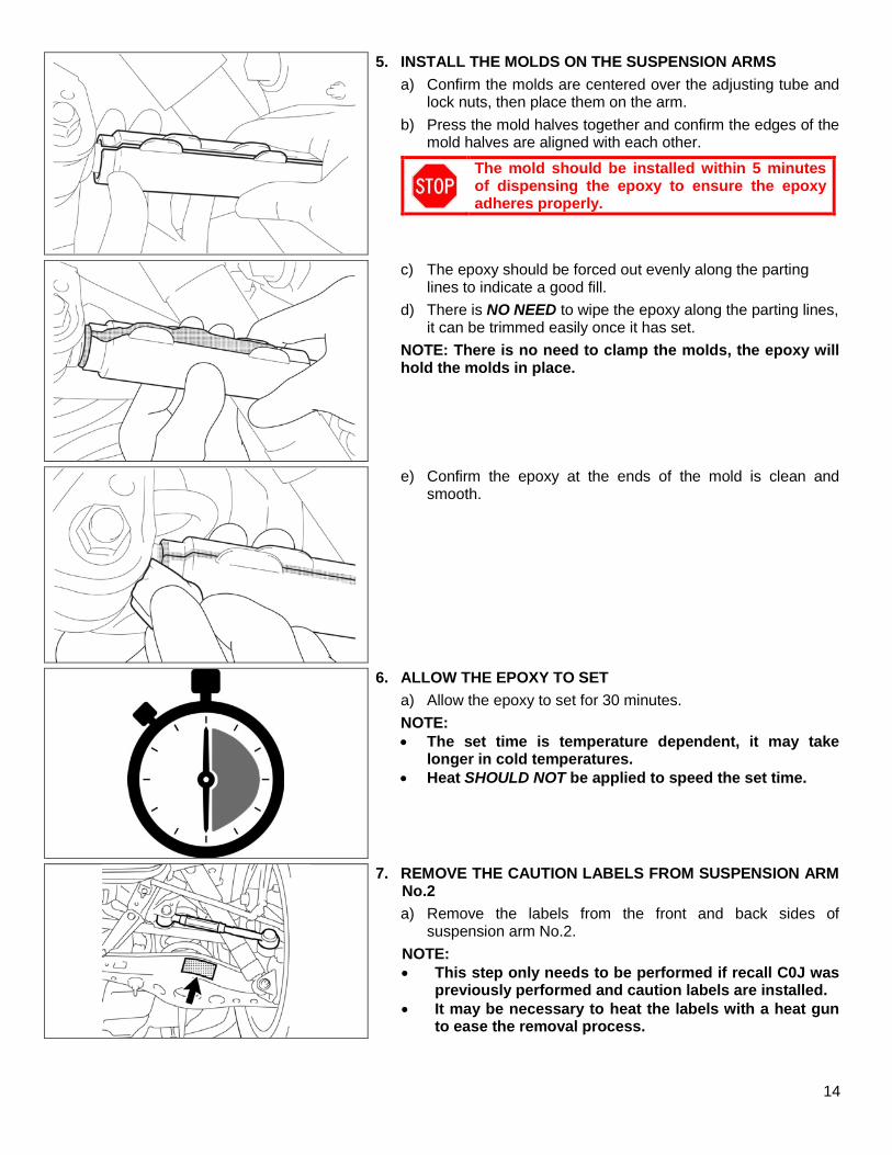
5. INSTALL THE MOLDS ON THE SUSPENSION ARMS
a) Confirm the molds are centered over the adjusting tube and lock nuts, then place them on the arm.
b) Press the mold halves together and confirm the edges of the mold halves are aligned with each other.
The mold should be installed within 5 minutes of dispensing the epoxy to ensure the epoxy adheres properly.
c) The epoxy should be forced out evenly along the parting lines to indicate a good fill.
d) There is NO NEED to wipe the epoxy along the parting lines, it can be trimmed easily once it has set.
NOTE: There is no need to clamp the molds, the epoxy will hold the molds in place.
e) Confirm the epoxy at the ends of the mold is clean and smooth.
6. ALLOW THE EPOXY TO SET
a) Allow the epoxy to set for 30 minutes.
NOTE: • The set time is temperature dependent, it may take
longer in cold temperatures. • Heat SHOULD NOT be applied to speed the set time.
7. REMOVE THE CAUTION LABELS FROM SUSPENSION ARM No.2
a) Remove the labels from the front and back sides of suspension arm No.2.
NOTE: • This step only needs to be performed if recall C0J was
previously performed and caution labels are installed. • It may be necessary to heat the labels with a heat gun
to ease the removal process.
14

8. REMOVE THE MOLDS
a) If temperatures are cold, confirm the epoxy has set by touching it prior to removing the molds.
b) After the epoxy has set for a minimum of 30 minutes, the molds can be removed.
c) Use a screwdriver on the mold tabs to remove the molds.
• DO NOT remove the molds early or the epoxy may be damaged.
• DO NOT twist the molds during removal, this may deform the epoxy.
• It is normal for the epoxy to still be flexible, the epoxy will continue to cure over the next 6-8 hours.
9. TRIM AND CLEAN THE EPOXY
a) Trim the excess epoxy from the parting lines using a razor.
NOTE: The excess epoxy MUST be trimmed to confirm the caution label adheres properly.
b) Wipe the epoxy clean using a shop cloth to remove any remaining mold release.
DO NOT use brake clean on the epoxy.
Identify Void Fill Void
10. INSPECT FOR VOIDS
a) Inspect the epoxy for any voids that expose the arm.
b) If any voids are identified, fill with FIPG.
There should not be any voids that expose the arm if the molds are filled with epoxy correctly.
11. APPLY CAUTION LABEL
a) Wrap the caution label around the epoxy.
NOTE: The label is designed to overlap over itself by approximately 3/8”.
12. REMOVE THE OWNER’S MANUAL SUPPLEMENT
a) Remove and discard the owner’s manual supplement located in the glove box.
NOTE: This step only needs to be performed if recall C0J was previously performed and owner’s manual supplement can be found in the glove box.
13. CAMPAIGN COMPLETE
15

◄ VERIFY REPAIR QUALITY ► − Confirm ALL inspection steps are followed EXACTLY as described in these instructions − Confirm the lock nut tightening procedure is followed EXACTLY as described in these instructions if the
arm is being replaced − Confirm vehicle alignment is correct prior to applying epoxy to the arm − Confirm the epoxy is applied correctly and that the caution label is installed
If you have any questions regarding this update, please contact your regional representative. IX. APPENDIX
A. CAMPAIGN DESIGNATION DECODER
C S J
Year Campaign is Launched
B = 2011C = 2012 D = 2013E = 2014F = 2015
Etc...
Repair Phase
1st Campaign = A2nd Campaign = B
Etc...
Current Campaign Letter for this year
0 = Remedy1 = Interim (Remedy not yet available) “1”
will change to “0” when the Remedy is
availableS = Supplemental
Campaign
Examples: A0D = Launched in 2010, Remedy Phase, 4th Campaign Launched in 2010 B1M = Launched in 2011, Interim Phase, 13th Campaign Launched in 2011 CSJ = Supplemental Campaign for 9th Campaign Launched in 2012
B. CAMPAIGN PARTS DISPOSAL
As required by Federal Regulations, please make sure all campaign parts (original parts) removed from the vehicle are disposed of in a manner in which they will not be reused, unless requested for parts recovery return.
16