technical letter report: an overview of non-lwr vessel
TRANSCRIPT
ANL/NSE-21/3
Technical Letter Report: An Overview of Non-LWR Vessel Cooling Systems for Passive Decay Heat Removal Final Report
Manuscript Published: May, 2021
Prepared by Darius Lisowski, Qiuping Lv, Bogdan Alexandreanu, Yiren Chen, Rui Hu, Tanju Sofu Nuclear Science and Engineering Division Argonne National Laboratory, Lemont, IL 60439
Imtiaz Madni, NRC Senior Reactor Systems Engineer; Task Lead Maryam Khan, NRC Project Manager; Contracting Officer’s Representative Joseph Sebrosky, NRC Senior Project Manager; Alternate Contracting Officer’s Representative Prepared for Division of Advanced Reactors and Non-Power Production and Utilization Facilities Office of Nuclear Reactor Regulation U.S. Nuclear Regulatory Commission Washington, DC 20555

This page is intentionally left blank

An Overview of Non-LWR Vessel Cooling Systems for Passive Decay Heat Removal May 2021
ii ANL/NSE-21/3
Abstract
The following report provides a technical review of various reactor vessel cooling system (VCS) concepts under consideration for decay heat removal (DHR) in non-light water advanced reactor designs. This review focuses on ex-vessel designs, including the Reactor Cavity Cooling System (RCCS), the Reactor Vessel Auxiliary Cooling System (RVACS), and hybrid iterations, using both air and water cooling to achieve their heat removal function. Based on a literature review of publicly available sources published between 1979 and 2021, a technical summary is presented detailing existing and planned VCS design options, their applicability to specific reactor type, and review of authored research and development studies. Following an assessment of the availability of data and modeling tools, an evaluation was performed analyzing their likely performance during normal, degraded, and accident conditions, including reliability, stability, and longevity.
With renewed consideration of air-based DHR systems by some US vendors, there is a need to fully understand the complexities inherent to natural circulation systems, and more importantly, how they may influence safety-related heat removal functions and system performance. For DHR systems that rely on air-based mode of cooling, this entails quantification of the impacts of low flow conditions during start-up, relative elevations of inlet and outlet ducts for below-grade installations, effects of the use of multiple parallel chimneys for redundancy, and impact of weather conditions at the plant site. For systems relying on water-based mode cooling, reliance on limited coolant inventory in an event of pipe break or extended duration accident scenarios, sensitivities related to stability of boiling flow and heat transfer conditions, and quantification of full-scale structural vibrations on balance of plant structures are among the complicating factors.
Paperwork Reduction Act Statement
This report does not contain information collection requirements and, therefore, is not subject to the requirements of the Paperwork Reduction Act of 1995 (44 United States Code [U.S.C.] 3501 et seq.).
Public Protection Notification
The U.S. Nuclear Regulatory Commission (NRC) may not conduct or sponsor, and a person is not required to respond to, a request for information or an information collection requirement unless the requesting document displays a current valid Office of Management and Budget (OMB) control number.

An Overview of Non-LWR Vessel Cooling Systems for Passive Decay Heat Removal May 2021
ANL/NSE-21/3 iii
Table of Contents
ABSTRACT ................................................................................................................................................ II TABLE OF CONTENTS ........................................................................................................................ III LIST OF FIGURES ................................................................................................................................... V LIST OF TABLES .................................................................................................................................. VII ACKNOWLEDGMENTS .................................................................................................................... VIII ABBREVIATIONS AND ACRONYMS ................................................................................................. IX 1. INTRODUCTION .............................................................................................................................. 1
1.1. PROJECT OBJECTIVES .................................................................................................................. 2 1.2. LITERATURE SEARCH METHODOLOGY ........................................................................................ 3
2. REQUIREMENTS / EXPECTATIONS FOR SAFETY GRADE DECAY HEAT REMOVAL 4 2.1. HEAT REMOVAL CAPACITY ......................................................................................................... 5 2.2. PERFORMANCE AND OPERATING CHARACTERISTICS .................................................................. 6 2.3. BEHAVIOR IN ACCIDENT AND DEGRADED OPERATIONAL CONDITIONS ..................................... 7 2.4. QUALIFICATION WITH COMPUTATIONAL AND EXPERIMENTAL METHODS ................................. 7 2.5. REDUCED SCALE EXPERIMENTAL STUDIES ................................................................................. 8
3. OVERVIEW OF DHR CONCEPTS ................................................................................................ 9 3.1.1. In-Vessel DHR ....................................................................................................................... 10 3.1.2. Ex-Vessel DHR ...................................................................................................................... 10 3.1.3. Secondary / Intermediate DHR ............................................................................................. 10
3.2. VARIOUS GEOMETRIC DESIGNS OF EX-VESSEL DHR ............................................................... 11 4. TECHNICAL REVIEW OF THE RCCS ...................................................................................... 13
4.1. GA MHTGR AIR-BASED RCCS ................................................................................................ 16 4.2. FRAMATOME SC-HTGR WATER-BASED RCCS ........................................................................ 22 4.3. JAERI HTTR WATER-BASED VCS ........................................................................................... 26 4.4. FUTURE JAERI HTGR WATER-BASED VCS ............................................................................. 29 4.5. X-ENERGY XE-100 RCCS ......................................................................................................... 31 4.6. RUSSIAN VGM WATER-BASED RCCS ...................................................................................... 31 4.7. CHINESE HTR-10 WATER-BASED RCCS ................................................................................... 35
5. TECHNICAL REVIEW OF THE RVACS ................................................................................... 37 5.1. GE-HITACHI PRISM RVACS .................................................................................................... 40 5.2. ROCKWELL INTERNATIONAL SAFR RVACS ............................................................................ 43 5.3. TERRAPOWER NATRIUM RVACS ............................................................................................. 45 5.4. ADVANCED HIGH-TEMPERATURE REACTOR (AHTR) RVACS ................................................ 45 5.5. TERRESTRIAL ENERGY IMSR IRVACS .................................................................................... 47 5.6. PHENIX EMERGENCY COOLING SYSTEM ................................................................................... 50 5.7. CLEAR-I RVACS ..................................................................................................................... 51 5.8. ELSY RVACS ........................................................................................................................... 53
6. ASSESSMENT OF AVAILABLE DATA & MODELING TOOLS ........................................... 54

An Overview of Non-LWR Vessel Cooling Systems for Passive Decay Heat Removal May 2021
iv ANL/NSE-21/3
6.1. REVIEW OF RCCS PREVIOUS STUDIES ...................................................................................... 54 6.1.1. Air-cooled RCCS ................................................................................................................... 54 6.1.2. Water-cooled RCCS .............................................................................................................. 69 6.1.3. Hybrid RCCS Variations ....................................................................................................... 84
6.2. REVIEW OF RVACS PREVIOUS STUDIES ................................................................................... 95 6.3. BREADTH OF EXPERIMENTAL TESTING EFFORTS .................................................................... 101 6.4. VALIDATION & VERIFICATION OF ANALYTICAL AND MODELING TOOLS .............................. 104
7. BEHAVIOR DURING OFF-NORMAL AND DEGRADED CONDITIONS .......................... 108 7.1. RCCS ....................................................................................................................................... 108
7.1.1. Blockage of Riser Flow Channels ....................................................................................... 108 7.1.2. Flow Path Short Circuit ...................................................................................................... 111 7.1.3. Non-Air Gas Ingress ........................................................................................................... 112
7.2. RVACS .................................................................................................................................... 114 7.2.1. Blockages of Air Inlets and Outlets ..................................................................................... 115 7.2.2. Complete Blockage of Air Inlets .......................................................................................... 116 7.2.3. Complete Blockage of Air Outlets ....................................................................................... 117 7.2.4. Complete Blockage at Silo Bottom ...................................................................................... 118 7.2.5. Tolerance to Reactor Silo Water Seepage ........................................................................... 119
8. EVALUATION OF RELIABILITY AND PERFORMANCE................................................... 121 8.1. SYSTEM LONGEVITY OVER PLANT LIFETIME .......................................................................... 121 8.2. METEOROLOGICAL INFLUENCES ............................................................................................. 122
8.2.1. Ambient Air Temperature .................................................................................................... 123 8.2.2. Start-up Sensitivity .............................................................................................................. 124 8.2.3. Wind Gusts, Air-RCCS Chimney ......................................................................................... 125 8.2.4. Wind Gusts, RVACS Air Intake ........................................................................................... 126
8.3. NATURAL CIRCULATION STABILITY ....................................................................................... 129 8.3.1. Parallel Channels ................................................................................................................ 129 8.3.2. Air Cooled Vessel Cooling Systems .................................................................................... 129
8.3.2.1. Start-up Sensitivity and Control of Weather Effects ................................................................ 130 8.3.3. Water Cooled Vessel Cooling Systems ................................................................................ 131
8.3.3.1. Instability Mechanisms ............................................................................................................ 132 8.3.3.2. Structural Vibrations from System Oscillations ....................................................................... 133
9. SUMMARY .................................................................................................................................... 134 REFERENCES ........................................................................................................................................ 136

An Overview of Non-LWR Vessel Cooling Systems for Passive Decay Heat Removal May 2021
ANL/NSE-21/3 v
List of Figures
Figure 1: Distribution of references in the database by (a) publication year, and (b) topic/DHR system ..................... 3 Figure 2: Reactor power and air RCCS heat removal, SRDC-11 accident condition, GA-MHTGR [4] ...................... 5 Figure 3: Summary of various decay heat removal systems common to SFRs ............................................................. 9 Figure 4: Geometric design various of various ex-vessel DHR concepts .................................................................... 12 Figure 5: Water RCCS design overview (left); Layout within concrete containment (right) [72] .............................. 13 Figure 6: Sketch of GA-MHTGR reactor building. Air RCCS highlighted in red [4] ................................................. 14 Figure 7: Air-based RCCS concept for GA-MHTGR design [4] ................................................................................ 17 Figure 8: GA-MHTGR RCCS design flow diagram [4] .............................................................................................. 18 Figure 9: GA-MHTGR RCCS cooling panel design, plan view [4] ............................................................................ 19 Figure 10: GA-MHTGR RCCS design duct system [4] .............................................................................................. 20 Figure 11: GA-MHTGR RCCS cooling panel design, elevation view [4] .................................................................. 21 Figure 12: Conceptual layout of single SC-HTGR module [6][112][99] .................................................................... 24 Figure 13: The SC-HTGR RCCS natural circulation loop configuration [112][99] .................................................... 24 Figure 14: The SC-HTGR RCCS schematic diagram [112] ........................................................................................ 25 Figure 15: The SC-HTGR RCCS cooling panel tube and fin details [112] ................................................................. 25 Figure 16: Reactor cooling system of HTTR [104][12] .............................................................................................. 27 Figure 17: Flow diagram of the HTTR VCS [12] ........................................................................................................ 28 Figure 18: Advanced VCS for HTTR and proposed future HTGR [21] ...................................................................... 29 Figure 19: Valve actuating system of the advanced VCS [21] .................................................................................... 30 Figure 20: Heat transfer path for passive heat removal in X-energy Xe-100 [105] ..................................................... 31 Figure 21: VGM reactor plant [61] .............................................................................................................................. 32 Figure 22: Arrangement of the RCCS, units in mm [2] ............................................................................................... 33 Figure 23: Cooling tube layout for the VGM RCCS, units in mm [2] ......................................................................... 34 Figure 24: Simplified model of the HTR-10 water-based RCCS [62] ......................................................................... 36 Figure 25: RVACS conceptual layout for a generic reactor [28] ................................................................................. 37 Figure 26: Schematic of the PRISM of RVACS system [106] .................................................................................... 38 Figure 27: PRISM safety grade systems [85] .............................................................................................................. 41 Figure 28: Schematic of GE-Hitachi PRISM RVACS [85] ......................................................................................... 42 Figure 29: Passive and localized safety features of SAFR [31] .................................................................................. 43 Figure 30: Decay heat removal system performance for SAFR [31]. ......................................................................... 44 Figure 31: Plant concept for the Terrapower Natrium reactor[32] .............................................................................. 45 Figure 32: Schematic of an AHTR with RVACS and external intermediate heat exchanger [34] .............................. 46 Figure 33: IRVACS system of Terrestrial Energy IMSR [35] .................................................................................... 48 Figure 34: IRVACS system of Terrestrial Energy IMSR [35] ................................................................................... 49 Figure 35: Schematic of the Phenix reactor vessel cooling [36] .................................................................................. 50 Figure 36: (a) CLEAR-I RVACS schematic diagram; (b) Three-dimensional structure [116] ................................... 52 Figure 37: RVACS and RPCS pipe bundle, schematic layout [50] ............................................................................. 53 Figure 38: RCCS panel cross section [64] ................................................................................................................... 55 Figure 39: Plan view of modeled RCCS for the 350 MWt MHTGR [65] ................................................................... 56 Figure 40: Active core and vessel temperature during SRDC-11 for the 450 MWt MHTGR [65] ............................. 57 Figure 41: Decay heat generation and RCCS heat removal rate during SRDC-11, 450MW MHTGR [65]................ 57 Figure 42: Vessel and riser panel temperature profiles during SRDC-11 for the 350 MWt MHTGR [65] ................. 59 Figure 43: Schematic of the riser mockup for air-based RCCS testing [66] ................................................................ 60 Figure 44: Experiment range compared to prototypic MHTGR operation regime [66] .............................................. 61 Figure 45: Measured isothermal friction factors compared with the Petukhov correlation [66] ................................. 61 Figure 46: CFD model (left) and CAD model (right) of the Texas A&M RCCS test facility [67] ............................. 62 Figure 47: CAD model of the 1:2 scale air-based modern NSTF experimental program at Argonne [59] ................. 63 Figure 48: Upper support plate for rectangular risers in the 1:2 scale air-based NSTF [58] ....................................... 64 Figure 49: Schematic of GT-MHR, thermal output of 600 MWth, and an air-based RCCS [84] ............................... 66 Figure 50: Effect of the graphite volumetric heat capacity [70] .................................................................................. 67 Figure 51: Effect of the graphite thermal conductivity [70] ........................................................................................ 67 Figure 52: Maximum reactor fuel and vessel temperatures in depressurized LOFC with RCCS failure [70] ............. 68 Figure 53: Effect of removing the cavity insulation [70]............................................................................................. 68 Figure 54: Illustration of the proposed water RCCS for modular 200 MWt HTGR [23] ............................................ 70
An Overview of Non-LWR Vessel Cooling Systems for Passive Decay Heat Removal May 2021
vi ANL/NSE-21/3
Figure 55: Horizontal cross section of the proposed water RCCS for modular 200 MWt HTGR [23] ....................... 70 Figure 56: Schematic of the VCS for the Japanese HTGR [110][24] .......................................................................... 72 Figure 57: Calculated heat removal capability of the HTTR VCS [20]....................................................................... 73 Figure 58: HTTR VCS thermal radiation test results (left) and heat removal value test results (right) [20] ............... 73 Figure 59: Comparison of temperature transients: with and without VCS failure [12] ............................................... 74 Figure 60: Outline of the experimental apparatus by Takada for the water-cooled RCCS [25] .................................. 75 Figure 61: Scaled test facility for water-based RCCS by Vaghetto and Hassan, 2014 [26] ........................................ 76 Figure 62: Schematic of the water RCCS test facility at UW – Madison [72] ............................................................ 78 Figure 63: Comparison of variation in initial tank inventory in 1:4 scale RCCS testing [72] ..................................... 79 Figure 64: Mass flow rates at different power levels in scaled water RCCS [72] ....................................................... 79 Figure 65: Installation of water cooling panel test section during construction of water NSTF [86] .......................... 82 Figure 66: Observed flow instabilities and phase regime mapping, boiling tests with water NSTF [87] .................... 83 Figure 67: Illustration of the hybrid RCCS concept [14] ............................................................................................ 85 Figure 68: Schematic of the hybrid RCCS test facility [14] ........................................................................................ 86 Figure 69: Picture of the hybrid RCCS test facility [13] [14] ...................................................................................... 87 Figure 70: Schematic diagram of the test section for the separate effect test [63]....................................................... 88 Figure 71: Comparison of the forced air temperature at pipe center (top) and pool water temperature (bottom), CFX
vs experiment [63] ............................................................................................................................................. 89 Figure 72: Temperature distribution with Mori-Nakayama correlation (top), Dittus-Boelter correlation (middle), and
constant HTC from SET (bottom), MARS-GCR vs experiment [63] ................................................................ 90 Figure 73: Experimental results of the heat transfer coefficient for the RCCS cooping pipes [13][14] ...................... 91 Figure 74: Ansys CFX results showing the centrifugal effect of the cooling pipe bends [14] .................................... 91 Figure 75: Schematic of the new design LFDRS [15] ................................................................................................. 92 Figure 76: Temperature distribution of a new RCCS using novel shape [16] ............................................................. 94 Figure 77: Analytical model of the novel RCCS and the calculated temperature distribution [19]............................. 94 Figure 78: 1980's Argonne scaled RVACS test assembly parameters and available performance map [56] ............. 95 Figure 79: Layout and dimensions of scaled RVACS test facility at Argonne [56] ................................................... 96 Figure 80: Photograph of experimental test section from 1980’s RVACS testing at Argonne [51] ............................ 97 Figure 81: Schematic representations of six designs [37] ............................................................................................ 99 Figure 82: Four stages of riser blockages in the air-based NSTF, red arrows indicate heated surface [58] .............. 108 Figure 83: Time history of system flow rate with various blockage stages indicated [58] ........................................ 109 Figure 84: Step change in flow rate as a function of riser blockage [58] .................................................................. 110 Figure 85: Sequence from air to argon by-pass testing performed on a 1:2 scale air-based RCCS [77] ................... 112 Figure 86: Riser gas inlet and outlet temperatures of the NSTF with non-air gas ingress [77] ................................. 113 Figure 87: Average core sodium outlet temperature for natural operating conditions [47] ....................................... 114 Figure 88: U-air flow model for natural convection flow pattern in RVACS hot air riser with total blockage of air
inlets [47] ......................................................................................................................................................... 116 Figure 89: Average core sodium outlet temperature for blocked inlets case [47] ..................................................... 117 Figure 90: U-air flow model for natural convection flow pattern in RVACS cold air downcomer with total blockage
of air outlets [47] .............................................................................................................................................. 118 Figure 91: RVACS airflow path and configuration for flooding analysis [47] ......................................................... 120 Figure 92: Rust collected from bottom of scaled air-based RCCS test facility over 100-day period [58] ................. 121 Figure 93: Engineered drain of an air-based RCCS for anticipated water ingress [81] ............................................. 121 Figure 94: Relationship between standard air temperature and density [79] ............................................................. 122 Figure 95: Relation between heated RCCS ΔT and ambient temperature in air-based NSFT [58] ........................... 123 Figure 96: System wide reverse flow observed on air-based NSTF created elevated temperatures [58] .................. 124 Figure 97: Impact on the otherwise calm cool-down period after Run018 from a sudden wind gust [58] ................ 125 Figure 98: Configuration plan for wind study on RVACS [44]................................................................................. 128 Figure 99: Types of two-phase flow instabilities observed in a 1:4 scale water-based RCCS. A. Nucleate boiling, B.
Hydrostatic head fluctuations, C. Pure flashing, D. Parallel channel interaction, E. Density wave oscillation, E. Geysering. [72]................................................................................................................................................. 131
Figure 100: Mapping of stability regimes in 1:2 scaled water-RCCS with boiling [87] ........................................... 132 Figure 101: Structural vibration generated by boiling flow in 1:2 scale water-RCCS [87] ....................................... 133

An Overview of Non-LWR Vessel Cooling Systems for Passive Decay Heat Removal May 2021
ANL/NSE-21/3 vii
List of Tables
Table 1: Summary of reactor designs featuring the RCCS concept for decay heat removal ....................................... 15 Table 2: GA-MHTGR air-based RCCS design features [4] ........................................................................................ 16 Table 3: The SC-HTGR RCCS operation modes, DLOFC & DBA ............................................................................ 22 Table 4: SC-HTGR water-based RCCS design features .............................................................................................. 22 Table 5. Design summary of the cavity cooler, HTR-10 [2] ....................................................................................... 36 Table 6: Summary of reactor designs featuring the RVACS concept for decay heat removal .................................... 39 Table 7: Key design parameters of the reference reactor design, modified GT-MHR [70] ......................................... 65 Table 8: Nominal DCC results for the SC-HTGR water-based RCCS design [22] ..................................................... 80 Table 9: Conservative DCC results for the SC-HTGR water-based RCCS design [22] .............................................. 80 Table 10 Overview of primary dimensions and operating parameters of the water-based NSTF [82] ....................... 81 Table 11. Heat transfer improvement by the new RCCS design approach, LFDRS [15] ............................................ 93 Table 12: Summary of known experimental efforts on RCCS and RVACS ex-vessel cooling systems for decay heat
removal ............................................................................................................................................................ 103 Table 13: Summary of known computational and modeling tools for RCCS and RVACS ex-vessel cooling systems
for decay heat removal ..................................................................................................................................... 107 Table 14: Summary of air-based NSTF testing at various stages of degraded riser channel flow area [58] ............. 110 Table 15: System behavior with varying amounts of chimney short-circuit break areas [58] ................................... 111 Table 16: Split in air distribution across break and heated region [58] .................................................................... 111 Table 17: Average core sodium outlet temperature for natural operating conditions [47] ........................................ 115

An Overview of Non-LWR Vessel Cooling Systems for Passive Decay Heat Removal May 2021
viii ANL/NSE-21/3
Acknowledgments
This work is sponsored by the Office of Nuclear Reactor Regulation, U.S. Nuclear Regulatory Commission.
Argonne National Laboratory Argonne is a U.S. Department of Energy laboratory managed by UChicago Argonne, LLC under contract DE-AC02-06CH11357. The Laboratory’s main facility is outside Chicago, at 9700 South Cass Avenue, Lemont, Illinois 60439. For information about Argonne and its pioneering science and technology programs, see www.anl.gov.

An Overview of Non-LWR Vessel Cooling Systems for Passive Decay Heat Removal May 2021
ANL/NSE-21/3 ix
Abbreviations and Acronyms
Argonne Argonne National Laboratory ALMR Advanced Liquid Metal Reactor ASME American Society of Mechanical Engineers BWR Boiling Water Reactor DBA Design Basis Accident DCC Depressurized Conduction Cooldown DHR Decay Heat Removal P/DLOFC Pressurized/Depressurized Loss of Forced Convection DRACS Direct Reactor Auxiliary Cooling System GA General Atomics GCR Gas Cooled Reactor GE General Electric GE-H General Electric - Hitachi HTR High Temperature Reactor HTGR High Temperature Gas-cooled Reactor HTTR High Temperature Test Reactor IMSR Integral Molten Salt Reactor IAEA International Atomic Energy Agency INL Idaho National Laboratory IRACS Intermediate Reactor Auxiliary Cooling System JAERI Japan Atomic Energy Research Institute LFDRS Liquid Metal Filled Decay Heat Removal System LFR Lead-cooled Fast Reactor LOCA Loss of Cooling Accident LOFC Loss of Forced Cooling LWR Light Water Reactor MHTGR Modular High Temperature Gas-cooled Reactor MSR Molten Salt Reactor NGNP Next Generation Nuclear Plant NQA Nuclear Quality Assurance NRC Nuclear Regulatory Commission NSTF Natural convection Shutdown heat removal Test Facility PBMR Pebble Bed Modular reactor PRACS Primary Reactor Auxiliary Cooling System PRISM Power Reactor Innovative Small Modular RCCS Reactor Cavity Cooling System R&D Research and Development RELAP Reactor Excursion and Leak Analysis Program RV Reactor Vessel RPV Reactor Pressure Vessel RVACS Reactor Vessel Auxiliary Cooling System SC-HTGR Steam Cycle High Temperature Gas-cooled Reactor SFR Sodium Fast Reactor SGACS Steam Generator Auxiliary Cooling System SNL Seoul National University SRDC Safety-Related Design Condition VCS Vessel Cooling System VHTR Very High Temperature Reactor V&V Verification and Validation

An Overview of Non-LWR Vessel Cooling Systems for Passive Decay Heat Removal May 2021
ANL/NSE-21/3 1
1. Introduction
One of the leading focus areas in the development of advanced reactor concepts is the use of passive safety systems as a primary means for decay heat removal. Of the proposed concepts under consideration, several approaches rely on radiative and convective cooling of the reactor vessel to remove decay heat from the reactor core and achieve safe shutdown conditions. These ex-vessel cooling systems offer a high level of performance with relative simplicity and passive safety. Unique to non-light water reactors, several of the proposed Generation IV concepts including High Temperature Gas-cooled Reactors (HTGRs), Sodium-cooled Fast Reactors (SFRs), and Lead-cooled Fast Reactors (LFRs) feature some variant of safety grade vessel cooling systems.
A common feature of most vessel cooling systems is the use of an air- or water-based natural circulation flow loop which can transfer heat directly from the reactor vessel to the ultimate heat sink. Some designs are fully passive and require no human action or component operation, while others require actuation of a burst disk, valve manipulation, material phase change, etc. Thus, such cooling systems span a diverse set of designs and are applicable to different reactor types; nonetheless, each aims to achieve a safe and reliable means to remove decay heat in transient scenarios.
Even in the event of loss of site power, many of these systems are able to provide paths for decay heat to reach an ultimate heat sink without the need for active AC or DC power sources. While serving a primary purpose of preventing fuel from reaching or exceeding temperature thresholds, they also provide adequate cooling to maintain vessel and containment structures within allowable limits.
The design and use of such technologies date to the earliest high-temperature gas-cooled reactors, which were built and operated in the 1950s. With the introduction of new and alternative reactor types, these systems have been adapted to meet specific operational and safety needs. To date, a significant amount of research has been conducted on the design, testing, and performance of various concepts. Furthermore, the advancement of modern computing has allowed for significant advances in modeling and simulation, leading to exploration of systems and their behaviors that have not yet been observed experimentally.
For any vessel cooling system to serve as a viable feature for safety basis reactor licensing, vendors will have to defend their ability to maintain the intended safety function throughout the operating life of the reactor. A key question, therefore, is the availability and breadth of technical data that can quantify the performance and behavior across the full range of normal operation, accident scenarios, and degraded operating conditions.

An Overview of Non-LWR Vessel Cooling Systems for Passive Decay Heat Removal May 2021
2 ANL/NSE-21/3
1.1. Project Objectives
The objective of this project is to provide a thorough technical review of air- and water-based reactor vessel cooling systems, such as Reactor Vessel Auxiliary Cooling System (RVACS) and Reactor Cavity Cooling Systems (RCCS) considered for future advanced, non-LWR concepts. This review includes a summary of proposed design concepts, a summary of research completed to date, and an assessment of the performance and operating characteristics during normal operation, accidents, and degraded conditions (with consideration of potential passive component failures and their impact on system reliability). The goal is to examine how such systems are designed to perform and how degraded conditions can impact their safety function.
This review is intended to assist in the assessment of the maturity, performance, and viability of reactor vessel cooling systems for decay heat removal in advanced non-LWR reactor concepts. To develop a knowledge base for the assessment and performance of these systems, a thorough technical review was performed and used as the basis for evaluation metrics. Several high-level objectives have been identified to facilitate achieving the project goal, including:
A. Technical review of design concepts for vessel cooling systems a. Summary of vessel cooling design options b. Design history and maturity c. Applicability to various reactor types
B. Evaluation and Assessment
a. Operating characteristics during normal operation and accident conditions b. Performance during degraded operation and impact on design function c. Discovery of available data
C. Regulatory considerations
a. Applicability of current regulations b. Associated limits and constraints for safety grade decay heat removal c. Areas of consideration during NRC review of licensing applications d. Assessment of the adequacy of the current regulation and guidance

An Overview of Non-LWR Vessel Cooling Systems for Passive Decay Heat Removal May 2021
ANL/NSE-21/3 3
1.2. Literature Search Methodology
For this project, a database was generated consisting of 471 openly available publications that reference efforts related to the design, analysis, testing, and optimization of decay heat removal systems. The distribution of publication year is shown in Figure 1, with the earliest available publication dating back to 1979 and the most recent publication from 2020. From this collection, 184 publications were determined to be highly relevant to the ex-vessel cooling focus of this report.
(a)
(b)
Figure 1: Distribution of references in the database by (a) publication year, and (b) topic/DHR system

An Overview of Non-LWR Vessel Cooling Systems for Passive Decay Heat Removal May 2021
4 ANL/NSE-21/3
2. Requirements / Expectations for Safety Grade Decay Heat Removal
The role of decay heat removal systems is to remove core afterheat in the case of failure or unavailability of primary cooling systems. These systems establish a pathway for heat rejection to an ultimate heat sink, ensuring that peak temperatures of fuel, core structures, vessel(s), and other critical equipment remain within safe levels. The ex-vessel cooling systems leverage convective and/or radiative cooling of the surface of the reactor or guard vessels, while in-vessel systems leverage heat transfer directly from the primary coolant. Regardless of the specific mechanism for heat removal, all designs then employ a secondary network of forced or natural draft cooling to transfer the heat to an ultimate heat sink.
The decay heat removal system designs feature any number of passive, highly-reliable, and/or redundant features to accomplish their heat removal function. Other safety related terms such as fault-tolerant, walk-away safe, fully passive, etc. are also used to describe the characteristics and performance of these systems. When inherent hazards cannot be eliminated, engineered safety systems help to establish sufficient confidence in the reliability and performance of these safety systems decay heat removal function across normal and accident conditions [78].
The designs of various concepts are typically based on an individual vendor’s need to balance requirements with preferred features. For example, the choice to maintain an “always-on” approach removes the need for operator intervention and serves to provide reliable cooling over the entire spectrum and duration of postulated accident scenarios, but it also introduces parasitic heat loss that reduces the available electric power output. Regardless of design decisions or variations across specific reactor types, these concepts share a number of minimum operating requirements:
1. Maintain fuel and reactor vessel temperatures within safe limits 2. Passive mode of operation during safety-related accident conditions 3. Reliable operation during both accident transients and over the course of plant life 4. Heat removal rate commensurate with rate of decay fission generation

An Overview of Non-LWR Vessel Cooling Systems for Passive Decay Heat Removal May 2021
ANL/NSE-21/3 5
2.1. Heat Removal Capacity
Upon reactor shutdown, a portion of the fission energy continues to be emitted by short-lived isotopes and residual decay of fission products. In the form of gamma and beta radiation, they are released after a time delay which extends the period of core heat generation. This delayed energy, also known as decay heat or afterheat, can account for approximately 6% of the nominal reactor power immediately after shutdown, 1% after one hour, and approximately 0.2% of the original nominal core power even after 100 hours post-shutdown [1]. Given that full power often succeeds hundreds of MW, this decay heat is significant and must be removed in order to avoid exceeding safe temperature limits of the reactor.
The actual rate of heat transfer from the fission products within the fuel to an external ultimate heat sink is a complex problem that drives many of the requirements for engineering design of safety grade vessel cooling systems. Due to multiple thermal conduction and convection paths within the reactor core, there is a delay between the heat generation and heat removal. Furthermore, there is a tight coupling of ex-vessel heat transfer to in-vessel heat conduction/convection that creates a feedback system highly dependent on the specific thermal and geometric conditions. The delay in decay heat generation and subsequent heat removal for an air-based RCCS in one prototypic gas-cooled reactor concept, the General Atomics MHTGR, is shown in Figure 2. In this specific example, the reactor has experienced the SRDC-11 accident scenario, a depressurized conduction cooldown with small primary leak. Vessel temperatures and heat removal rates by the RCCS peak after approximately 120 hours, reaching levels of 441°C and 1.50MW, respectively.
Figure 2: Reactor power and air RCCS heat removal, SRDC-11 accident condition, GA-MHTGR [4]

An Overview of Non-LWR Vessel Cooling Systems for Passive Decay Heat Removal May 2021
6 ANL/NSE-21/3
2.2. Performance and Operating Characteristics
The requirements for performance and operating characteristics of safety grade DHR systems are highly dependent on their specific role and functional purpose. Furthermore, the inclusion of supplementary or parallel heat removal systems can allow for simplification of their design. Additionally, parallel systems also enable designers to reduce the overall failure probability by ensuring that redundant systems are available. VCS may serve a dual purpose of also maintaining concrete and support structures at safe limits during normal and accident conditions [2].
For systems that provide continuous heat rejection even during normal operation, it is often desirable to optimize their nominal heat removal capacity in order to reduce parasitic heat loss, which not only impacts the economics of a power reactor but increases the needs for higher capacity active heat rejection during normal operation. However, engineered controls for adjusting the heat removal rate during different conditions may not be advisable since mechanical control systems can introduce a higher probability of failure.
Another consideration is the potential for over-cooling of the vessel during reactor shutdown events, such as those necessary for refueling or maintenance. For coolants with high melting points, such as liquid metals or molten salts, over-cooling may create the need for additional requirements, such as trace heating systems. As with controls for adjusting the heat removal rate, this could similarly create new failure points that may reduce the overall plant reliability.
All DHR systems must have sufficient heat removal abilities in order to sufficiently dissipate core decay heat and transfer the power to an ultimate heat sink. Prior to licensing and commercial deployment, these features must be demonstrated under conditions representing realistic reactor operation. When analysis or computational methods are used to predict the performance of the fuel and reactor, they must also be validated with qualified experimental data.

An Overview of Non-LWR Vessel Cooling Systems for Passive Decay Heat Removal May 2021
ANL/NSE-21/3 7
2.3. Behavior in Accident and Degraded Operational Conditions
With nearly a century’s worth of knowledge related to the operation and development of nuclear reactors, reactor designers are able to leverage a vast amount of research and information from past events to guide design choices and plan for accident scenarios. For High-Temperature Gas-cooled Reactors (HTGR), design basis accidents (DBA) include such scenarios as loss of cooling accidents (LOCA), depressurized conduction cooldown, pressurized conduction cooldown, blocked cooling channels, etc. For Sodium-cooled Fast Reactors (SFR), the design basis accidents (DBA) include loss-of-flow, loss-of-heat-sink, and transient overpower scenarios.
Recent events have highlighted the need to also consider more extreme events such as sabotage, terrorism, aviation crashes, tsunamis, etc. The International Atomic Energy Agency (IAEA) has even stated that for reactors and all facilities concerned with fuel element supply and disposal, ‘no (reactor) catastrophic events may occur’. This requirement includes the control of all events from disturbances within the facility to severe external impacts on the facility [1][3].
While best engineering practices are used to consider and plan for all scenarios, there is still the possibility of unplanned events that may cause degraded performance or failure of reactor functions. Thus, safety grade DHR systems must not only meet the minimum requirements during planned accident conditions, but they must do so with ample margin and redundancy.
2.4. Qualification with Computational and Experimental Methods
For successful licensing and life-long performance of any safety grade decay heat removal system, the behavior and operating characteristics must be rigorously supported by qualified experimental results and validated computational analyses. Predictions related to behavior and operating characteristics must be demonstrated by experimental conditions and analytical tools that represent realistic reactor conditions. Ultimately, a designer must demonstrate high confidence in their ability to provide full scale performance during normal, degraded, and accident conditions.
There are currently a number of consensus and industry standards that guide the design and licensing requirements for advanced reactor concepts. For example, the Nuclear Regulatory Commission (NRC) has determined that “…NQA-1b-2011 Addenda to ASME NQA-1-2008, NQA-1-2012, and NQA-1-2015 provide the most current guidance for the implementation of a quality assurance program during design and construction phases of nuclear power plants and fuel reprocessing plants and meets the requirements of Appendix B to 10 CFR Part 50” [5].
The Nuclear Quality Assurance (NQA-1) standard contains guidance and requirements for the documentation, traceability, and quality standards to support technical and safety related processes. Given the complexity of test assemblies that are built to study the performance of various decay heat removal concepts, design and licensing programs often require a substantial effort to design, construct, and execute their research and development (R&D) activities. As a test

An Overview of Non-LWR Vessel Cooling Systems for Passive Decay Heat Removal May 2021
8 ANL/NSE-21/3
facility scales in size, the effort to maintain high confidence in precise dimensions and spatial positions becomes increasingly difficult. Compounded by the sensitive nature of natural circulation systems, stringent record keeping and traceability become critical for establishing high-quality data.
2.5. Reduced Scale Experimental Studies
Given the high cost and considerable effort associated with constructing large- or full-scale test facilities, studies are typically performed with one or more experiments at a reduced scale. However, to preserve key thermal hydraulic behavior and phenomena and ensure validity in predicting full-scale performance, it is necessary for any scaled studies to first establish a set of similarity relationships that can be used to define both integral performance and local behavior. Each level of scaling serves a purpose that supports the broader scaling scope, with system scaling preserving key performance behavior such as temperature rise, system mass flow rates, etc. with respect to a given geometry. For example, a top-down scaling approach preserves integral behavior for mass and energy balances, but it may not capture local behavior such as 3-dimensional mixing phenomena within inlet and outlet plena [7]. However, it does include behavior involving multiple riser ducts and parallel channel interactions. Natural circulation flow patterns common in many vessel cooling designs are characterized by low flow rates and small density differences (e.g. air driven systems), which exhibit complex behavior and are difficult to predict with confidence. These local behaviors are more difficult to control and often require separate experimental scales and testing platforms.
Work performed by M. Ishii for the design of the Purdue University Multi-Dimensional Integral Test Assembly (PUMA) established a three-level scaling process [8], a method that has been well recognized across the R&D community for scaling of thermal-hydraulic test facilities. The first level is based on the integral response function and ensures that the steady-state as well as dynamic characteristics of the loops are scaled properly. The second level is used for scaling of boundary flow of mass and energy between components, which ensures that the flow and inventory are scaled correctly. Finally, the third level of scaling is focused on the key local phenomena and constitutive relations.
With full-scale test facilities often impractical or otherwise not feasible, it may be necessary to conduct testing across multiple test facilities and computational codes at varying scales. With adequate planning and preparation to address scaling distortions, including a well formulated set of scaling similarity parameters and assurance that testing is similar and consistent across facilities, one can have high confidence that the resulting data sets can be used to accurately predict performance and behaviors of systems at prototypic scales.

An Overview of Non-LWR Vessel Cooling Systems for Passive Decay Heat Removal May 2021
ANL/NSE-21/3 9
3. Overview of VCS Concepts
Passive DHR systems have become one of the primary focus areas for meeting the technological goals of the Generation IV International Forum. In the event of an accident scenario, where external power is lost and subsequent failures of the cooling pumps occur, passive systems provide an ultimate heat sink for the decay power, thus preventing temperatures from reaching dangerous levels and ultimately preventing a core meltdown. With a robust design, these systems become an integral part of the power plant that often require no human intervention during an accident. Several concepts of reactor cooling systems have been proposed for the latest generation of non-LWR advanced reactors. Figure 3 illustrates various concepts common to SFRs, with systems such as the RCCS and RVACS also applicable to other advanced, Gen IV reactors types.
Figure 3: Summary of various decay heat removal systems common to SFRs

An Overview of Non-LWR Vessel Cooling Systems for Passive Decay Heat Removal May 2021
10 ANL/NSE-21/3
Efforts toward the development of DHR systems for advanced reactors have resulted in the proposal of various design concepts, with extensive associated analysis and testing programs. Based on their specific reactor components and cooling mechanisms, the DHR systems can roughly be divided into three different categories, as summarized below:
3.1.1. In-Vessel DHR
a. Direct Reactor Auxiliary Cooling Systems (DRACS) where decay heat removal is achieved by heat exchangers immersed directly in the coolant pool within the reactor vessel. The heat from the pool is transferred by dedicated intermediate loops to the primary side of secondary heat exchangers and then transferred to an ultimate heat sink by either air or water.
b. Primary Reactor Auxiliary Cooling Systems (PRACS) where decay heat is removed from the primary system by connections to dedicated auxiliary heat exchangers or by integrating the auxiliary units within intermediate heat exchangers. Similar to the DRACS, the heat is then transferred to secondary heat exchangers, with either air or water cooling.
3.1.2. Ex-Vessel DHR
c. Reactor Vessel Auxiliary Cooling Systems (RVACS) where decay heat is removed from the reactor and guard vessel walls by convection and/or radiation. The decay heat is transferred to air flowing within the cavity of the concrete containment and rejected to the environment directly, or through a secondary exchange by convection to water.
d. Reactor Cavity Cooling System (RCCS) where decay heat is removed by radiation and/or convection directly from the walls of the reactor pressure vessel (RPV) and into a network of standpipes containing air or water. The standpipes are housed within the concrete containment and spaced some distance away from the RPV. Compared to the RVACS, an RCCS provides an additional boundary layer of separation from reactor containment and the secondary coolant. Additionally, RCCS concepts operate in either fully passive natural circulation mode, or they are active during normal and passive during accident scenarios.
3.1.3. Secondary / Intermediate DHR
e. Intermediate Reactor Auxiliary Cooling System (IRACS) where decay heat is removed by a heat exchanger that is integrated into the secondary coolant loop. The heat is transferred by dedicated intermediate loops to air-cooled heat exchangers.

An Overview of Non-LWR Vessel Cooling Systems for Passive Decay Heat Removal May 2021
ANL/NSE-21/3 11
3.2. Various Geometric Designs of Ex-Vessel DHR
The remainder of this work will focus on a subset of the DHR systems that rely on ex-vessel cooling to achieve heat removal. The design of these systems, including the RCCS, RVACS, and their hybrid variations, share a commonality in the use of conductive, radiative and convective cooling from the walls of an RPV to a network of cooling channels. However, there are design variations that specific vendors have chosen to feature within their specific reactor type. In addition to design choices of air or water as the primary coolant, geometry and design of the individual cooling channels such dimensions of air or water pipes, vary widely across reactor designs. Shown in Figure 4 are conceptual sketches of examples proposed for various RCCS and RVACS systems for advanced reactor concepts.

An Overview of Non-LWR Vessel Cooling Systems for Passive Decay Heat Removal May 2021
12 ANL/NSE-21/3
Water-cooled RCCS “panel” design for the
Japanese HTTR [104][21] RVACS for the GE PRISM Air-based RCCS for the GA MHTGR [4]
Water-cooled RCCS “shield” design for Russian
VGM [2] Water-cooled RCCS “panel” for Framatome SC-
HTGR [84] Water-cooled RCCS “standpipe and curtain”
design for the South African PBMR [7]
Figure 4: Geometric design various of various ex-vessel DHR concepts

An Overview of Non-LWR Vessel Cooling Systems for Passive Decay Heat Removal May 2021
ANL/NSE-21/3 13
4. Technical Review of the RCCS
The RCCS is a passive safety system that has been proposed for use in high temperature gas reactors and their variants, and have been included as a primary design choice in concepts dating back to the 1950s. The RCCS is an external system outside the reactor pressure vessel (RPV), and is designed to remove core decay heat during both normal operation when active systems are available, and during accident scenarios when normal heat transport system or any other shutdown cooling system are assumed unavailable. Due to its relative simplicity, reliance on natural forces, and potential for high levels of performance, the RCCS stands out as a leading concept for the passive safety in the latest generation of High Temperature Gas Cooled Reactors (HTGR). Different RCCS concepts have been proposed for the range of reactor designs, with primary differences in their working fluid and passive mode of operation. Representative of these concepts is the air-based RCCS for the General Atomics (GA) Modular High Temperature Gas Cooled Reactor (MHTGR) design [4] and the water-based RCCS for the Framatome Steam Cycle – High Temperature Gas Cooled Reactor (SC-HTGR) [6],[8], with each featuring its own advantages and disadvantages. The air-based RCCS, Figure 6, features unlimited supply of the ambient air cooling but may be susceptible to certain ambient effects, e.g., strong winds. The water-based RCCS, Figure 5, exhibits a superior efficiency in heat transfer due to two-phase boiling, but its cooling capability is limited by the capacity of the water inventory tank. A summary of reactor designs featuring the RCCS concept for decay heat removal is provided in Table 1, and a technical overview of these two RCCS concepts is presented in the subsequent sections.
Figure 5: Water RCCS design overview (left); Layout within concrete containment (right) [72]

An Overview of Non-LWR Vessel Cooling Systems for Passive Decay Heat Removal May 2021
14 ANL/NSE-21/3
Figure 6: Sketch of GA-MHTGR reactor building. Air RCCS highlighted in red [4]

An Overview of Non-LWR Vessel Cooling Systems for Passive Decay Heat Removal May 2021
ANL/NSE-21/3 15
Table 1: Summary of reactor designs featuring the RCCS concept for decay heat removal
Specific reactor Country Vendor Thermal Power
Reactor Coolant Decay heat removal approach
Heat removal capacity
DHR Fluid
Circulation Mode
Ultimate heat sink Reference
MHTGR USA General Atomics 560 MWt Helium Reactor cavity cooling system
with air 1.5 MW Air Natural Atmosphere [4]
HTTR Japan JAERI 30 MWt Helium
Radiation heat transfer from reactor vessel to cooling tubes, forced convection heat transfer to eventual cooling water
0.3 MW Water Forced Cooling water [12]
Peach Bottom 1 USA Philadelphia Electric 115 MWt Helium Reactor-vessel cooling panels,
secondary system n/a n/a n/a n/a [113]
NPR-MHTGR USA General Atomics 350 MWt Helium
Water-cooled panels surrounding reactor vessel, cooled by heat exchanger above grade
n/a Water Natural and forced Atmosphere [115]
HTR Module Germany Siempelkamp/Siemens 200 MWt Helium
Radiation heat transfer from reactor vessel to cooling tubes, natural convection heat transfer to atmosphere, dry air cooling
890 kW Water Natural Atmosphere [23]
SC-HTGR France Framatome 625 MWt Helium Radiation heat transfer from RV to cooling panel with natural circulation of water inside
2.1 MW Water Natural Atmosphere [22]
PBMR South Africa
PBMR (Pty) Ltd 265 MWt Helium
Radiation heat transfer from RV to water pool, forced air circulation, evaporation or boiling
3.1 MW Water Forced air circulation Atmosphere [13]
GT-MHR US / Russia
GA & MINATOM 600 MWt Helium
Liquid metal filled reactor cavity to cool off the reactor vessel, and passive air flow to remove heat from reactor cavity.
1.5 MW Air Natural circulation Atmosphere [101]
HTR-PM China Huaneng Group 458 MWt Helium
Radiation heat transfer from reactor vessel to cooling tubes, forced convection heat transfer to eventual cooling water
1.1 MW Water Natural Atmosphere [102]
HTR-10 China Tsinghua University 10 MWt Helium
Radiation heat transfer from reactor vessel to cooling tubes, forced convection heat transfer to eventual cooling water
200 kW Water Natural Atmosphere [103]
VGM Russia OKMB 200 MWt Helium Radiation heat transfer from vessel to cooling tubes with back mounted fins
1.3 MW Water Natural Atmosphere [100]

An Overview of Non-LWR Vessel Cooling Systems for Passive Decay Heat Removal May 2021
16 ANL/NSE-21/3
4.1. GA MHTGR Air-based RCCS
The GA-MHTGR is a helium-cooled reactor with prismatic fuel elements in a hexagonal core. Each reactor module features a total thermal power of 350 MWt and an electrical output of 140 MWe. GA proposed a four-unit plant with two steam turbine generators, generating a total electrical power of approximately 560 MWe [4]. One unique feature of the GA-MHTGR is the employment of an uninsulated steel RV to provide a surface for passive decay heat removal via radiation and convection to the RCCS standpipes.
During a normal shutdown of the reactor, decay heat is removed through the normal heat transport system or secondary shutdown cooling systems. However, in the case of loss of both normal paths, decay heat is removed by the RCCS through thermal radiation and natural convection from the RPV to the RCCS cooling panels located within the reactor cavity and surrounding the RV. The RCCS draws cold air from the ambient environment and removes heat from the reactor cavity by natural circulation of the ambient air through the cooling panels and air ducts, as demonstrated in Figure 7. This RCCS design is always on, and it is completely passive with no valves or active components.
Each GA-MHTGR module is equipped with an independent RCCS, which consists of inlet/outlet structures and cooling panels, as shown in Figure 8 and Figure 10. The inlet/outlet structures are located above grade while the cooling panels are located below grade, surrounding the RV. The rectangular air inlet and outlet ducts are concentric, with the outlet duct insulated to minimize regenerative heating of the incoming air. The concentric ducts connect the inlet/outlet ports and the cooling panels, which join via manifolds to form plena near the inlet and outlet of the cooling panels. Four sets of inlet/outlet ports are employed and housed in two separate inlet/outlet structures to provide a high degree of redundancy in case of inlet/outlet blockage. In addition, the inlet/outlet ports are located high above grade and are equipped with screens to prevent unexpected external object intrusions. Another design feature of this RCCS is the use of quiescent chambers in the inlet and outlet ports to minimize the potential wind effect. The design features of the GA-MHTGR air-based RCCS are summarized in Table 2.
Table 2: GA-MHTGR air-based RCCS design features [4]
Reactor GA-MHTGR Reactor Power 140 MWe / 350 MWt Reactor Coolant He DHR Concept RCCS Number of Units 4 Working Fluid Air
Heat Removal Capacity
Power Scenario 718 kWt Normal operation 1.75 MWt Pressurized conduction cooldown, control rod withdraw 1.50 MWt Depressurized conduction cooldown, small primary leak
The cold-air downcomer is formed by two parallel vertical steel plates 25 cm apart, which are anchored to vertical steel channels at a space of approximately 0.6 m along the cavity wall, Figure

An Overview of Non-LWR Vessel Cooling Systems for Passive Decay Heat Removal May 2021
ANL/NSE-21/3 17
9. The inner surface of the downcomer facing the RV is covered with a layer of thermal insulation and a reflective surface to prevent regenerative heating of the incoming air. The downcomer is directly lined against the concrete wall of the reactor cavity to protect the concrete from the RV heat, Figure 11. The hot riser part of the cooling panel consists of 227 vertical rectangular carbon steel tubes spaced around the RV at a distance of 5 cm. Each rectangular riser tube has external dimensions of 5 cm wide by 25 cm deep with a 4.76-mm thick wall. The total number, cross-sectional shape, and configuration of the tubes are optimized for radiative and natural convective heat transfer, as well as for air flow. In addition, the gaps between riser tubes allow a fraction of the thermal radiation to reach the reflective surface and then bounce back to heat up the back side of the riser tubes, thus enhancing the utilization of the riser tube surface area and the heat transfer.
Since there are no valves or active components employed in the RCCS, it is always in operation. During normal operation of the reactor core, the RCCS function can lead to a parasitic heat loss that is estimated to be approximately 718 kWt. During accidents, the RCCS performance was analyzed at two typical “safety-related” design conditions (SRDCs) [4]. In the scenario of pressurized conduction cooldown with control rod withdrawal, the peak RCCS heat removal is approximately 1.75 MWt, while in the scenario of depressurized conduction cooldown with a small primary leak, the heat removal capacity is approximately 1.5 MWt.
Figure 7: Air-based RCCS concept for GA-MHTGR design [4]

An Overview of Non-LWR Vessel Cooling Systems for Passive Decay Heat Removal May 2021
18 ANL/NSE-21/3
Figure 8: GA-MHTGR RCCS design flow diagram [4]

An Overview of Non-LWR Vessel Cooling Systems for Passive Decay Heat Removal May 2021
ANL/NSE-21/3 19
Figure 9: GA-MHTGR RCCS cooling panel design, plan view [4]

An Overview of Non-LWR Vessel Cooling Systems for Passive Decay Heat Removal May 2021
20 ANL/NSE-21/3
Figure 10: GA-MHTGR RCCS design duct system [4]

An Overview of Non-LWR Vessel Cooling Systems for Passive Decay Heat Removal May 2021
ANL/NSE-21/3 21
Figure 11: GA-MHTGR RCCS cooling panel design, elevation view [4]

An Overview of Non-LWR Vessel Cooling Systems for Passive Decay Heat Removal May 2021
22 ANL/NSE-21/3
4.2. Framatome SC-HTGR Water-based RCCS
The Framatome Steam Cycle - High Temperature Gas Cooled Reactor (SC-HTGR) is a graphite-moderated helium-cooled reactor coupled directly to a steam generator to provide high-temperature steam for a variety of applications, including chemical processing and synthetic fuel production [6]. First introduced at the HTR Conference in 2010 [10], the SC-HTGR design concept was selected by the Next Generation Nuclear Plant (NGNP) Industry Alliance for near-term commercialization of HTGR technology in 2012 [11]. The SC-HTGR is a two-loop modular steam supply system, with each module containing one reactor coupled to two steam generators that are configured in parallel, each with its dedicated main circulator, Figure 12. The SC-HTGR features a thermal power of 625 MWt and electrical output of 272 MWe at full power.
The SC-HTGR RCCS has four distinct operating modes that are defined by the operational status of the plant and subsequent heat load on RCCS. These four operation modes include the normal plant operation and three accident scenarios, as summarized in Table 3. The estimated heat load is 1.4 MWt for normal plant operation, while 2.1 MWt for all three accident scenarios, [9]. The design features of the Framatome SC-HTGR water-based RCCS are summarized in Table 4.
Table 3: The SC-HTGR RCCS operation modes, DLOFC & DBA
Operation Mode # of Natural Circulation Loops in Operation
Active Water Tank Cooling?
Heat Load, MWt
Normal Plant Operation 2 Yes 1.4 Normal DLOFC Operation 2 Yes 2.1 Passive DLOFC Operation 2 No 2.1 DBA DLOFC Operation 1 No 2.1
Table 4: SC-HTGR water-based RCCS design features
Reactor SC-HTGR Reactor Power 272 MWe / 625 MWt Reactor Coolant He DHR Concept RCCS Number of Units 2 Working Fluid Water
Heat Removal Capacity
Power Scenario 1.4 MWt Normal operation 2.1 MWt Normal DLOFC operation, active cooling 2.1 MWt Passive DLOFC operation, design basis accident

An Overview of Non-LWR Vessel Cooling Systems for Passive Decay Heat Removal May 2021
ANL/NSE-21/3 23
During normal operation, the two main cooling loops transfer heat to a secondary circuit, which can also provide cooling during refueling and other shutdown conditions. During maintenance of the main cooling loops, a separate shutdown cooling system provides a separate heat removal path. However, in case of loss of both paths, decay heat is removed by the RCCS through thermal radiation and natural convection from the RPV to the RCCS cooling panel located in the reactor cavity and surrounding the RPV, similar to that of the GA-MHTGR. This heat removal process similarly does not require any moving components or activation of any standby systems. What distinguishes the SC-HTGR RCCS from the GA-MHTGR RCCS is a natural convection water-cooled system. In the SC-HTGR, the heat is removed from the reactor cavity by water instead of by air.
The SC-HTGR RCCS employs two parallel loops to ensure redundancy, Figure 13 and Figure 14. Each of the RCCS loops consists of alternating channels within a single cooling panel surrounding the reactor vessel, which is connected to multiple water storage tanks at higher elevations. Radiation heat transfer from the reactor vessel heats up the water inside the cooling panel, causing a decrease of the water density. With the driving head due to the lower density of water at low elevation and the higher density of water in the storage tank at high elevation, natural circulation flow is developed in the water loop. The RCCS can be operated in two modes, namely, the active mode and passive mode. During core normal operation, a separate non-safety active loop cools the inventory inside the water tank, thus providing continuous heat removal from the cavity and inventory within the RCCS. During accidents, the natural circulation water will be heated up to saturation and begin to boil. Due to the high specific heat capacity of liquid water, single-phase cooling is available for a period of several hours, if not days. Once saturation conditions are reached, the high latent heat of vaporization for water provides a period of continued heat removal capacity. The dual mode operation in single- and two-phase provide the necessary decay heat rejection to maintain acceptable temperatures for the fuel, reactor, and concrete shield. The water storage tank in each RCCS loop is designed to provide enough inventory and cooling for up to seven days. Upon continued depletion of the RCCS water during a sustained accident state, dry-out conditions can be avoided by replenishment of RCCS liquid inventory by plant operational staff or relief personnel.
The SC-HTGR RCCS cooling panel consists of a total of 230 vertical tubes that are laterally spaced but joined together through a series of full-height flat web fins. Figure 15 presents a top-view of the configuration of two adjacent riser tubes and the associated web fins. Based on recent design publication from Framatome, this design assumes standard 1.5” Sch. 160 pipe for the riser tubes, and nominal 5/16” carbon steel flat pate for the fins. In addition, to minimize the contact resistance, full-penetration weld is assumed to join the riser tubes and web fins. The parallel tubes are connected at top and bottom to two sets of circular inlet and outlet headers, thus forming two independent cooling loops. The riser tubes are connected in a way that adjacent tubes come from different cooling loops, which ensures 360° coverage of the reactor vessel even if one RCCS loop fails. The riser tubes are made of stainless steel to maintain good water chemistry, while the web

An Overview of Non-LWR Vessel Cooling Systems for Passive Decay Heat Removal May 2021
24 ANL/NSE-21/3
fins are made from carbon steel due to its high thermal conductivity. The emissivity of the RCCS cooling panel surface is a significant design constraint, though a target emissivity could be achieved through surface treatment.
Figure 12: Conceptual layout of single SC-HTGR module [6][112][99]
Figure 13: The SC-HTGR RCCS natural circulation loop configuration [112][99]

An Overview of Non-LWR Vessel Cooling Systems for Passive Decay Heat Removal May 2021
ANL/NSE-21/3 25
Figure 14: The SC-HTGR RCCS schematic diagram [112]
Figure 15: The SC-HTGR RCCS cooling panel tube and fin details [112]

An Overview of Non-LWR Vessel Cooling Systems for Passive Decay Heat Removal May 2021
26 ANL/NSE-21/3
4.3. JAERI HTTR Water-based VCS
The High Temperature Engineering Test Reactor (HTTR) is a graphite-moderated, helium-cooled reactor designed by the Japan Atomic Energy Research Institute (JAERI) to establish and upgrade the technological basis and to conduct various operation modes and tests for HTGRs. The HTTR employs VCS to indirectly remove decay heat from the reactor core during both pressurized and depressurized accidents [12], Figure 16.
The VCS is not a passive safety system because active components, specifically, water circulation pumps, are involved in the design, Figure 17. The HTTR employs two independent VCSs that are installed surrounding the reactor pressure vessel. Each VCS comprises upper, lower, and side cooling panels, as well as heat removal adjustment panels around the RPV. Cooling water is circulated by two water pumps, which transfer heat to a chilled water circuit to serve as the ultimate heat sink. The cooling panels consist of fins and water tubes and are installed against the inner surface of the concrete shield. Similar to the Framatome SC-HTGR RCCS design, these riser tubes are configured in a “water-wall” panel design and joined at their centerline by cooling fins. During normal operation and accidents, the VCS also helps to maintain the RPV and concrete shield temperatures below the design limits.

An Overview of Non-LWR Vessel Cooling Systems for Passive Decay Heat Removal May 2021
ANL/NSE-21/3 27
Figure 16: Reactor cooling system of HTTR [104][12]

An Overview of Non-LWR Vessel Cooling Systems for Passive Decay Heat Removal May 2021
28 ANL/NSE-21/3
Figure 17: Flow diagram of the HTTR VCS [12]

An Overview of Non-LWR Vessel Cooling Systems for Passive Decay Heat Removal May 2021
ANL/NSE-21/3 29
4.4. Future JAERI HTGR Water-based VCS
The HTGR of Japan is a helium gas cooled reactor with an inlet temperature of 395°C and an outlet temperature of 950°C. In this design, the VCS concept is safety-grade to heat from the reactor vessel during both normal and accident conditions. To maintain a high outlet temperature during normal operation, an advanced VCS concept is proposed to replace the current water-RCCS used in the earlier HTTR design [21]. The goal of this modified VCS is to minimize the heat loss during normal operations so that the designed outlet temperature of the primary coolant is attainable. In an accident condition, however, this advanced VCS can be activated and become highly efficient in removing decay heat. The design consists of cooling panels, a valve actuating system, and an air duct, as shown in Figure 18. Vertical internal fins are added to the cooling panel to enhance the convective heat transfer. The system can keep the concrete shield below 60°C and the RPV temperature below 480°C. The valve actuating system consists of butterfly valves, helium gas-induced pipes, piston, spring, and casing, as shown in Figure 19. During normal operation, the butterfly valves are off, and the confined air in the cooling panels helps insulate the heat loss from the RPV. During a depressurization accident, a differential pressure activates the butterfly valve, establishing natural air convection in the cooling panels. The heat from the reactor core is carried away by the VCS and released to the ambient atmosphere through air ducting. The maximum fuel and RPV temperatures are below the limits (1800°C and 550°C, respectively) during an accident. RPV temperatures could exceed the limits with reactor designs that feature thermal output, but this could be mitigated if additional heat transfer fins are added to the RPV.
Figure 18: Advanced VCS for HTTR and proposed future HTGR [21]
An Overview of Non-LWR Vessel Cooling Systems for Passive Decay Heat Removal May 2021
30 ANL/NSE-21/3
Figure 19: Valve actuating system of the advanced VCS [21]

An Overview of Non-LWR Vessel Cooling Systems for Passive Decay Heat Removal May 2021
ANL/NSE-21/3 31
4.5. X-Energy Xe-100 RCCS
The Xe-100, currently being developed by X-Energy, is a 200 MWt pebble bed helium-cooled high-temperature reactor. Using the steam Rankine cycle, its base model provides an electrical output of 80 MWe. The design features include high-temperature tolerant graphite core structure, 60-year operational life, flexible application including electricity generation and high-temperature process heat, and base load-following capability. Although an RCCS has been proposed as the passive decay heat removal system for Xe-100 [60], details of the design are not publicly available at the time of the present work.
Figure 20: Heat transfer path for passive heat removal in X-energy Xe-100 [105]
4.6. Russian VGM Water-based RCCS
The Russian VGM is a modular high-temperature helium-cooled reactor, developed in the late 1980s. It was designed to validate the main technical considerations related to the production of high-temperature process heat [2], [61]. Featuring a total thermal power of 200 MWt, the VGM reactor plant is shown in Figure 21, demonstrating the main components involved.
The VGM reactor employs a water-based RCCS, or ‘surface cooling system’, as stated by the authors, Figure 21 and Figure 22. Though similar to the water-based RCCS concepts proposed for the SC-HTGR and HTTR reactors, the VGM design is slightly modified and instead positions the thermal fins tangential to adjacent riser tubes, Figure 23. Otherwise, the operation modes and mechanisms are identical across the three RCCS designs. The VGM RCCS design employs a total of 432 cooling tubes that are divided into three independent units of 144 tubes each to ensure redundancy. The cooling tubes in the three units are staggered to ensure uniform heat removal upon failure of any single unit.

An Overview of Non-LWR Vessel Cooling Systems for Passive Decay Heat Removal May 2021
32 ANL/NSE-21/3
Figure 21: VGM reactor plant [61]

An Overview of Non-LWR Vessel Cooling Systems for Passive Decay Heat Removal May 2021
ANL/NSE-21/3 33
Figure 22: Arrangement of the RCCS, units in mm [2]

An Overview of Non-LWR Vessel Cooling Systems for Passive Decay Heat Removal May 2021
34 ANL/NSE-21/3
Figure 23: Cooling tube layout for the VGM RCCS, units in mm [2]

An Overview of Non-LWR Vessel Cooling Systems for Passive Decay Heat Removal May 2021
ANL/NSE-21/3 35
4.7. Chinese HTR-10 Water-based RCCS
The 10-MWth High-temperature gas-cooled Test Reactor (HTR-10) is a helium-cooled and graphite-moderated reactor designed to demonstrate the technical feasibility and safety of the pebble-bed reactor concept [2]. The HTR-10 was designed and constructed at the Nuclear Energy Institute of Technology (INET) of Tsinghua University, Beijing, which reached its first criticality in December 2000 and full capacity of 10 MWth in January 2003 [62]. The HTR-10 plant includes the reactor building, a turbine/generator building, two cooling towers, and a ventilation center and stack. The HTR-10 represents the main design features and safety characteristics of the advanced HTGR concept, including negative temperature reactivity feedback, passive decay heat removal capability through conduction, natural convection, and radiation, etc.
The passive decay heat removal capability of the HTR-10 is realized through two independent and parallel water-based RCCSs, designed with a nominal capacity of 125 kWt each [2]. Each RCCS consists of a cavity cooler located inside the reactor cavity, a cooler within an air chimney, a water tank, and associated connecting pipes, Figure 24. The cavity cooler consists of 50 parallel cooling tubes that are connected through steel fins, forming a cooling wall that surrounds the reactor vessel. The design information of the cavity cooler is summarized in Table 5. The air cooler consists of 60 finned tubes staggered in two rows, which are located in the air chimney built at the side of the reactor hall. The water tank stores the cooled water inventory from the air cooler and provides the coolant for the cavity cooling system.
During a reactor accident, decay heat is transferred to the ultimate heat sink of the ambient environment by both water and air natural circulation. As the water in the cavity cooler absorbs the heat transferred from the reactor vessel, its temperature is raised and density reduced, resulting in upward flow through buoyancy. After cooled by the air cooler, the water enters the water tank and flows down to the cavity cooler, forming a natural circulation flow loop. Additionally, the natural circulation of air is formed in the chimney as the air enters through the intake, becomes heated up by the air cooler, and eventually exhausts to the environment. There are regulated screens located at the air intake to control flows to minimize parasitic heat loss during core normal operation, as well as to avoid freezing problems in the air cooler.
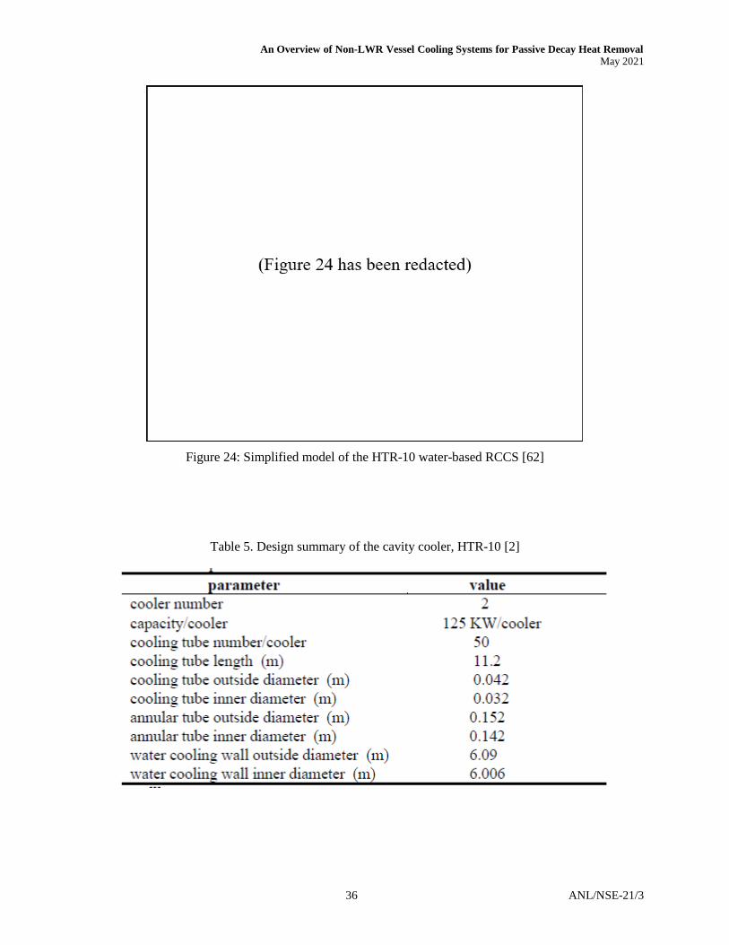
An Overview of Non-LWR Vessel Cooling Systems for Passive Decay Heat Removal May 2021
36 ANL/NSE-21/3
Figure 24: Simplified model of the HTR-10 water-based RCCS [62]
Table 5. Design summary of the cavity cooler, HTR-10 [2]
An Overview of Non-LWR Vessel Cooling Systems for Passive Decay Heat Removal May 2021
ANL/NSE-21/3 37
5. Technical Review of the RVACS
The Reactor Vessel Auxiliary Cooling System (RVACS) is designed to remove decay heat by radiative and convective cooling to natural circulation driven airflow across a guard vessel. Unlike the RCCS concept, air travels directly within the containment and requires special design constraints for potential fission product release and material activation. Although some alternative coolants have been proposed, e.g., oil-cooled circuits with a water sink [27], the majority of designs are based on the standard RVACS concept for the Generic Electric (GE) Hitachi Power Reactor Innovative Small Modular (PRISM) reactor. For illustration, Figure 25 displays a generic RVACS system [28], while Figure 26 [29] displays details specific to the PRISM reactor RVACS. The design is uniquely tailored toward the design of advanced liquid metal cooled reactors because the high conductivity of the coolant allows for effective heat transmission to the vessel and guard walls. Since the majority of RVACS designs operate in a passive, always-on mode of safety-grade operation, reactors that employ these designs experience parasitic heat loss during normal operation. A summary of reactor designs featuring the RVACS concept for decay heat removal is provided in Table 6.
Figure 25: RVACS conceptual layout for a generic reactor [28]

An Overview of Non-LWR Vessel Cooling Systems for Passive Decay Heat Removal May 2021
38 ANL/NSE-21/3
Figure 26: Schematic of the PRISM of RVACS system [106]

An Overview of Non-LWR Vessel Cooling Systems for Passive Decay Heat Removal May 2021
ANL/NSE-21/3 39
Table 6: Summary of reactor designs featuring the RVACS concept for decay heat removal
Specific reactor Country Vendor Thermal
Power Reactor Coolant DHR Approach
Heat removal capacity
(% full power)
Circulation Mode
DHR Fluid
Short Citation
PRISM USA General Electric 840 MWt Sodium RVACS with air 0.7 Natural Air [47]
SAFR USA Rockwell 900 MWt Sodium RVACS with air 0.6 Natural Air [31]
Natrium USA Terrapower 345 MWt Sodium RVACS with air unknown Natural Air [114]
IMSR Canada Terrestruial 400 MWt Molten Salt IRVACS with Nitrogen unknown Natural Nitrogen [35]
Phenix France CEM 840 MWt Sodium RVACS with water 0.4 (0.7) Forced Water [36] Super Phenix France Novatome 3000 MWt Sodium RVACS with water 0.2 Forced Water [36]
ASTRID France CEA 1500 MWt Sodium RVACS with air/water, oil unknown Natural Air/Water [27]
AHTR USA ORNL 2400 MWt Molten Salt RVACS, similar to PRISM unknown Natural Air [33]
W LFR USA Westinghouse 400 MWt Lead RVACS with air unknown Natural Air [98]
SSTAR USA LLNL 45 MWt Lead RVACS with air unknown Natural Air [107]
PEACER Korea SNU 850 MWt Lead RVACS with air unknown Natural Air [111]
ELSY EU Euratom 600 MWt Lead RVACS with air unknown Natural Air [50]
CLEAR-I China CAS 45 MWt Lead RVACS with air tubes 0.2 Natural Air [49]

An Overview of Non-LWR Vessel Cooling Systems for Passive Decay Heat Removal May 2021
40 ANL/NSE-21/3
5.1. GE-Hitachi PRISM RVACS
The GE-Hitachi PRISM is a pool-type, metal-fueled, small modular Sodium Fast Reactor (SFR). PRISM uses metallic fuel, such as an alloy of zirconium, uranium, and plutonium, with their fuel rods residing in a pool of liquid sodium metal. Though blanketed with an inert cover gas, the pool is maintained at atmospheric pressures. The GE-Hitachi PRISM has a rated power of 840 MWt and an output of 311 MWe, with planned installations containing two reactors totaling a combined output power of 622 MWe. The reactor plant includes an intermediate sodium loop that exchanges heat between the primary coolant within the core and a secondary water loop via sodium to water steam generator [29] [30]. A diagram of the PRISM safety-grade and high-grade heat transfer systems is shown in Figure 27.
PRISM employs two primary safety-grade heat removal systems: An Auxiliary Cooling System (ACS) and the RVACS, Figure 28. During reactor shutdown, heat is primarily removed by the turbine condenser using the turbine bypass, with the ACS serving as an alternative method for shutdown decay heat removal during maintenance or repair operations. The ACS uses natural or forced circulation of atmospheric air to remove heat as the air flows past the shell side of the steam generator (SG). The ACS consists of an insulated shroud around the SG shell with an air intake at the bottom through the annulus and an isolation damper located above the SG building. Natural circulation is initiated by opening the exhaust damper.
The PRISM RVACS is designed with a heat removal capacity sufficient to maintain reactor temperatures well below design limits using only air-based natural circulation to remove heat from the reactor guard vessel [52]. In the event of a beyond design basis accident, the metallic core expands with rising internal temperatures, and its density decreases slowing the fission reaction. This design feature is based on a highly coupled core with high leakage that provides for a reliable and less complex shutdown through the use of inherent means of negative temperature and power coefficients [85]. PRISM’s very conductive metal fuel and metal coolant then readily dissipates excess heat through RVACS without damaging any of its components.

An Overview of Non-LWR Vessel Cooling Systems for Passive Decay Heat Removal May 2021
ANL/NSE-21/3 41
Figure 27: PRISM safety grade systems [85]

An Overview of Non-LWR Vessel Cooling Systems for Passive Decay Heat Removal May 2021
42 ANL/NSE-21/3
Figure 28: Schematic of GE-Hitachi PRISM RVACS [85]

An Overview of Non-LWR Vessel Cooling Systems for Passive Decay Heat Removal May 2021
ANL/NSE-21/3 43
5.2. Rockwell International SAFR RVACS
The team of Rockwell International, Combustion Engineering, and Bechtel worked on developing the Sodium Advanced Fast Reactor (SAFR) [31] as an element in the United States (US) Department of Energy (DOE) Advanced Liquid-Metal Reactor (LMR) program. The SAFR plant concept consists of one or more 350-MWe pool-type LMR ‘Power Packs’ with inherent capability for shutdown and cooling under most design basis circumstances. Reactor decay heat removal is provided by two reliable, independent, redundant, and diverse passive systems that function in addition to the normal heat removal path through the intermediate and steam systems, Figure 29 and Figure 30. The coolant is maintained at least 440°F (244°C) below boiling by either of the two passive systems: one (RVACS) removing heat by natural convection of air on the outside of the reactor guard vessel, and the other (DRACS) removing heat through a natural draft sodium-to-air heat exchanger. Johnson et al. believe the SAFR plant can be built and operated as predicted, and proposed that a single 350-MWe module be built and tested to demonstrate the SAFR's inherent safety features and performance characteristics. Since publication, no further work by the authors for this concept has been performed.
Figure 29: Passive and localized safety features of SAFR [31]

An Overview of Non-LWR Vessel Cooling Systems for Passive Decay Heat Removal May 2021
44 ANL/NSE-21/3
Figure 30: Decay heat removal system performance for SAFR [31].

An Overview of Non-LWR Vessel Cooling Systems for Passive Decay Heat Removal May 2021
ANL/NSE-21/3 45
5.3. TerraPower Natrium RVACS
The Natrium reactor and energy system architecture, recently introduced by TerraPower and GE Hitachi Nuclear Energy, offers baseload electricity output from a 345-MWe sodium fast reactor with the load-following flexibility of molten salt thermal storage. While detailed plans have not been made publicly available, it is anticipated [32] that the base decay heat removal will be similar to the GE-PRISM RVACS.
Figure 31: Plant concept for the Terrapower Natrium reactor[32]
5.4. Advanced High-Temperature Reactor (AHTR) RVACS
The Advanced High-Temperature Reactor (AHTR) is a low-pressure, liquid-salt cooled high-temperature reactor designed for the production of electricity and hydrogen, [33][34]. The high temperature (950°C) variant is defined as the liquid-salt-cooled very high-temperature reactor (LS-VHTR). The AHTR has the same safety goals and uses the same graphite-matrix coated particle fuel as similar modular high-temperature gas-cooled reactors. However, the large AHTR power output (2,400 to 4,000 MWt) implies the need for a different type of passive decay-heat removal system. Three classes of passive decay heat removal systems have been identified as suitable candidates: the reactor vessel auxiliary cooling system (RVACS) which is similar to that proposed for the GE S-PRISM; a DRACS similar to that used in the Experimental Breeder Reactor EBR-II; and a new pool reactor auxiliary cooling system.
A schematic of AHTR is shown in Figure 32 which includes a VCS reflective of the RVACS concept. This reactor operates at near-atmospheric pressures, and at nominal power conditions, the
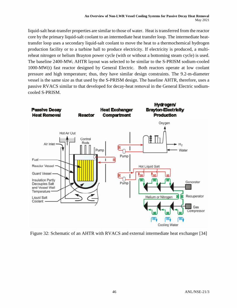
An Overview of Non-LWR Vessel Cooling Systems for Passive Decay Heat Removal May 2021
46 ANL/NSE-21/3
liquid-salt heat-transfer properties are similar to those of water. Heat is transferred from the reactor core by the primary liquid-salt coolant to an intermediate heat transfer loop. The intermediate heat-transfer loop uses a secondary liquid-salt coolant to move the heat to a thermochemical hydrogen production facility or to a turbine hall to produce electricity. If electricity is produced, a multi-reheat nitrogen or helium Brayton power cycle (with or without a bottoming steam cycle) is used. The baseline 2400-MWt AHTR layout was selected to be similar to the S-PRISM sodium-cooled 1000-MW(t) fast reactor designed by General Electric. Both reactors operate at low coolant pressure and high temperature; thus, they have similar design constraints. The 9.2-m-diameter vessel is the same size as that used by the S-PRISM design. The baseline AHTR, therefore, uses a passive RVACS similar to that developed for decay-heat removal in the General Electric sodium-cooled S-PRISM.
Figure 32: Schematic of an AHTR with RVACS and external intermediate heat exchanger [34]

An Overview of Non-LWR Vessel Cooling Systems for Passive Decay Heat Removal May 2021
ANL/NSE-21/3 47
5.5. Terrestrial Energy IMSR IRVACS
The Integral Molten Salt Reactor (IMSR) is being developed by the Canadian company Terrestrial Energy for the small modular reactor (SMR) market and is currently working to license a reactor design with a power capacity of 400 MWt, [48].
The IMSR design is based closely on the denatured molten salt reactor (DMSR), a reactor design originating from Oak Ridge National Laboratory (ORNL). The design uses a replaceable core-unit, i.e., when the graphite moderator's exposure to neutron flux causes it to start distorting beyond acceptable limits, rather than remove and replace the graphite moderator, the entire IMSR core-unit is replaced as a unit. The replacement process includes the pumps, pump motors, shutdown rods, heat exchangers, and graphite moderators, all of which are either inside the vessel or directly attached to it.
Under routine operations, the IMSR relies on intrinsic stability for reactivity control, as there are no control rods. This behavior is known as negative power feedback: the reactor is self-stabilizing in power output and temperature and is characterized as a load-following reactor. Reactor power is controlled by the amount of heat removed from the reactor; increased heat removal results in a reduction in fuel salt temperature, resulting in increased reactivity and in-turn, increased power output. Conversely, reducing heat removal will increase reactor temperature at first, lowering reactivity and subsequently reducing the reactor power. If all heat removal is lost, the reactor power will drop to a very low power level.
For cooling, the always-on passive cooling system is based on heat loss, thus enabling safety-grade decay heat removal. The IMSR decay cooling mechanism does not require backup electric power and functions similar to other RVACS concepts. One of the drawbacks of the RVACS design for MSR use includes the potential activation of passing air to Argon-41 (110 minutes half-life), hence, significant neutron shielding would be required to bring Ar-41 rates to acceptable levels. Also, any remote possibility of breach of containment would create a relatively direct pathway for radionuclides. Hence, the proposed IRVACS (“Internal” RVACS) is a closed cycle innovation of the RVACS system that retains a further barrier to the outside world, Figure 33 and Figure 34. The IRVACS transfers heat by a closed cycle flow of nitrogen to a false roof acting as a large heat exchanger above the structural roof.

An Overview of Non-LWR Vessel Cooling Systems for Passive Decay Heat Removal May 2021
48 ANL/NSE-21/3
Figure 33: IRVACS system of Terrestrial Energy IMSR [35]

An Overview of Non-LWR Vessel Cooling Systems for Passive Decay Heat Removal May 2021
ANL/NSE-21/3 49
Figure 34: IRVACS system of Terrestrial Energy IMSR [35]

An Overview of Non-LWR Vessel Cooling Systems for Passive Decay Heat Removal May 2021
50 ANL/NSE-21/3
5.6. Phenix Emergency Cooling System
Phenix is a sodium-cooled pool-type fast reactor of 563 MWth (250MWe) which features suspended reactor blocks [36]. Operation of the reactor began in 1973, was converted to reduced power of 350 MWt in 1993, and finally shut down in 2009. The upper cover slab supports all of the vessels, ensures biological protection, and includes various penetrations for the passage of components. The main vessel, 11.8 m in diameter and holding approximately 800 tons of primary sodium, is attached to the upper slab by twenty-one suspension hangers. The pool is sealed from the environment through a flat roof, with an additional double-envelope vessel welded to the upper region of the main vessel, which serves the purpose of containing any possible sodium leaks. A third vessel, the primary containment vessel, is welded to the slab underside and attached to the reactor pit. The role of this vessel is to contain radioactive products, in the event of a severe accident. A schematic of the cooling system is provided in Figure 35. The system was initially supplied with water from the Rhône River but was later connected to air coolers in 2002.
Figure 35: Schematic of the Phenix reactor vessel cooling [36]

An Overview of Non-LWR Vessel Cooling Systems for Passive Decay Heat Removal May 2021
ANL/NSE-21/3 51
5.7. CLEAR-I RVACS
The China Lead-based Research Reactor (CLEAR-I) is a 10 MWth lead-bismuth cooled research reactor that has sub-critical and critical dual-mode operation capability for Accelerator Driven System (ADS) for nuclear waste transmutation. The reactor features a traditional RVACS [29] concept and is designed to remove the decay heat in full during any accident scenarios.
The overall configuration of CLEAR-I RVACS is shown in Figure 36 [49]. The system is composed of the main vessel, a safety vessel, a thermal insulating layer, a concrete silo, and U-shape air tubes placed outside of the reactor safety vessel. The main vessel is surrounded by a safety vessel, which is surrounded by air collector tubes. The gap between the main and safety vessels is filled with air. The independent U-shape air tubes are all connected to a manifold which guides the airflow to the chimney. Atmospheric air is drawn into the U-shape air tubes between the safety vessel and collector cylinder to provide the ultimate heat sink. CLEAR-I RVACS is provided with four independent inherently safe loops by natural convection circulation to assure a high safety level. The heat removal involves several heat transfer mechanisms, which include:
1. Convection between the lead-alloy pool and the main vessel 2. Conduction and natural convection in the air gap between the main and safety vessels 3. Radiation from the outer surface of the main vessel to the inner of the safety vessel 4. Radiation between the outer surface of the safety vessel and air collector tubes 5. Convection between the inner surface of air collector tubes and atmospheric air in the
air collector tubes
The heat removal capability of CLEAR-I RVACS was analyzed by using the RELAP5 code, [49], and the results showed that CLEAR-I RVACS could remove the CLEAR-I decay heat during most design basis scenarios. The maximum heat removal capability of CLEAR-I RVACS was also studied, and it was found that the CLEAR-I RVACS could be utilized as an independent decay heat removal system.

An Overview of Non-LWR Vessel Cooling Systems for Passive Decay Heat Removal May 2021
52 ANL/NSE-21/3
Figure 36: (a) CLEAR-I RVACS schematic diagram; (b) Three-dimensional structure [116]

An Overview of Non-LWR Vessel Cooling Systems for Passive Decay Heat Removal May 2021
ANL/NSE-21/3 53
5.8. ELSY RVACS
The European Lead cooled System (ELSY) was proposed to investigate the economic feasibility of using critical reactors for nuclear waste transmutation. The 600 MWe reactor proposes to use compact, in-vessel steam generators and a simple primary circuit with all internals being potentially removable. Given the predicted low primary system pressure loss and the favorable thermodynamic characteristics of lead, decay heat can be removed in natural circulation in the primary system. The system for decay heat removal is based on a modified RVACS, which consists of an annular pipe bundle of U-pipes arranged in the reactor pit with atmospheric air flowing pipe-side in natural circulation, Figure 37 [50]. In the case of ELSY, the RVACS performance is sufficient only in the long term (after about one month after shut down) and an additional four loops equipped with coolers immersed in the primary system are needed. Because of the greater complexity, the in-vessel systems will result in lower reliability than the simple RVACS. Safety requirements are expected to be achieved by redundancy and diversification. Hence, a Reactor Pit Cooling System (RPCS) is additionally included for use during an in-service inspection of the reactor vessel.
Figure 37: RVACS and RPCS pipe bundle, schematic layout [50]

An Overview of Non-LWR Vessel Cooling Systems for Passive Decay Heat Removal May 2021
54 ANL/NSE-21/3
6. Assessment of Available Data & Modeling Tools
With a technical review of proposed ex-vessel DHR concepts presented, including an overview of previous studies, the objective of this section is to provide a summary of available data and modeling tools. It is noted however that the availability is limited to those results published in the open literature, and does not extend into the access of full data sets that may be under the ownership of individual authors or institutions.
6.1. Review of RCCS Previous Studies
6.1.1. Air-cooled RCCS
Extensive analytical and modeling studies were performed in preparation for the NRC review of the GA-MHTGR design proposal, including features and performance of the safety-grade air-based RCCS decay heat removal system. Conklin, 1990 [64] performed a dynamic simulation for the GA-MHTGR air-based RCCS using an in-house code that was later included in the MORECA code. MORECA is a reactor simulation code that has been developed at Oak Ridge National Laboratory (ORNL) for the prediction of overall MHTGR plant transient response. The RCCS design that was studied was slightly different from the design discussed previously, Figure 38. Instead of using separate hot riser tubes and a reflective surface, an integral cooling panel with all the hot riser tubes connected was investigated. A dynamic simulation was developed and tested independently from the reactor vessel and core dynamic simulation to validate its functionality, with uniform reactor vessel temperature assumed. They first investigated the temperatures and flows at full reactor power normal operating conditions, and then proceeded to sensitivity studies of computed RCCS temperatures and air flows to the surface emissivity and presence of steam in the reactor cavity. It was found that the RCCS performance is highly dependent on the surface emissivity for both the reactor vessel and hot riser tubes, and periodic monitoring of the RCCS panel and reactor vessel surfaces was recommended to ensure the safety function of the RCCS throughout the operation life of the MHTGR.
Other efforts toward assessing the adequacy of the RCCS design for the GA-MHTGR included Dilling et al., 1992 [65], which performed a detailed analysis to simulate the decay heat removal process and predict the maximum reactor vessel temperature during depressurized conduction cool down (DPCC) accidents. The safety-related design condition SRDC-11 was selected for the analysis 136[4], in which a small primary coolant leak was assumed at the top of the reactor vessel depressurizing the reactor system in 24 hours, along with loss of both the heat transport system and the shutdown cooling system. The author first performed a transient thermal analysis for an updated 450 MWt MHTGR design using the two-dimensional heat transfer code TAC2D, with the entire reactor vessel and cavity modeled. The thermal transient experienced by the active core and reactor vessel during SRDC-11 showed a slow increase to peak temperatures at roughly 60 and 100 hours respectively, followed by a gradual cool down, Figure 40. The RCCS heat removal rate followed the same trend as the reactor vessel, but peaked at a later time of approximately 140 hours

An Overview of Non-LWR Vessel Cooling Systems for Passive Decay Heat Removal May 2021
ANL/NSE-21/3 55
due to the non-uniformity of the vessel temperature, Figure 41. Also, the RCCS heat removal rate reached approximately 1.5 MW when exceeding the decay heat generation rate at approximately 70 hours. This heat rate was then assumed as the load for the subsequent steady-state RCCS performance analysis for the reference 350 MWt MHTGR.
The COMMIX code developed at the Argonne National Laboratory was used for the simulation, though only a quadrant of the reactor cavity was modeled to save the cost of computer runs, Figure 39. The simulation results confirmed the adequacy of the RCCS heat removal capability to keep the reactor vessel temperatures within acceptable limits, Figure 42. Furthermore, the results showed that the combined effects of thermal radiation, natural convection, and non-uniformity of RCCS geometry can strongly affect the RCCS heat removal process and reactor vessel temperature distributions.
Figure 38: RCCS panel cross section [64]

An Overview of Non-LWR Vessel Cooling Systems for Passive Decay Heat Removal May 2021
56 ANL/NSE-21/3
Figure 39: Plan view of modeled RCCS for the 350 MWt MHTGR [65]

An Overview of Non-LWR Vessel Cooling Systems for Passive Decay Heat Removal May 2021
ANL/NSE-21/3 57
Figure 40: Active core and vessel temperature during SRDC-11 for the 450 MWt MHTGR [65]
Figure 41: Decay heat generation and RCCS heat removal rate during SRDC-11, 450MW MHTGR [65]

An Overview of Non-LWR Vessel Cooling Systems for Passive Decay Heat Removal May 2021
58 ANL/NSE-21/3
For the GA-MHTGR RCCS, the heat transfer from the reactor vessel to the ultimate air sink involves different heat transfer mechanisms, including radiation and natural convection in the cavity, as well as convective heat transfer inside the riser tubes, each of which play an important role in the heat transfer process. Accordingly, Fu, 1991 [66] designed and constructed a riser mockup test facility to investigate the heat transfer and friction pressure loss of mixed convection air flow expected in the prototypic RCCS riser tubes, Figure 43. The experiment range was carefully considered to ensure a complete encompassing of the prototypic MHTGR operation regime, Figure 44. The measured isothermal friction factors were in good agreement with the correlations provided by literature, Figure 45. The measured Nusselt (Nu) number results were also consistent with theoretical predictions by Dittus-Boelter correlation, especially at low Bond (Bo) number. With the experimental support, the author developed a computer code called RECENT (Reactor Cavity Energy Transfer) to calculate the integral heat removal capability of the RCCS from the reactor vessel to the ambient air, including detailed models of the radiation and inside-cavity convective heat transfer as well as their coupling to the riser tube internal convection. The simulation model consisted of a one-unit cavity cell that include a single riser tube, vessel wall and cavity wall, one chimney, and one cold flow path. The author first simulated a nominal case defined based on the standard design parameters, and predicted a reactor vessel wall temperature of 679.62 K, well below the design limit of 811 K. Parametric studies were also performed to guide optimization of the RCCS design, covering the effects of surface emissivity, vessel surface heat flux, riser wall conduction, inside-riser radiation and cavity convection, riser heat transfer coefficient and friction factor, and RCCS configuration. Findings of the parametric studies were: i) The decay power level had the most significant effect on the reactor vessel temperature; ii) The effect of riser wall emissivity was much less than that of the vessel wall emissivity, which is insignificant when above ε ≈ 0.6; iii) Heat conduction within the riser wall and the inside-riser radiation between the riser walls can not only smooth the riser wall temperature distribution, but also affect the vessel wall temperature indirectly; iv) Large variations of the riser heat transfer coefficient and friction factor within the possible riser operating regime had a significant effect on the vessel wall temperature, and thus RCCS performance; v) The riser location inside the cavity had an insignificant effect on the vessel wall temperature for a prototypic distances; however, the shape of the riser was determined to affect the vessel wall temperature.

An Overview of Non-LWR Vessel Cooling Systems for Passive Decay Heat Removal May 2021
ANL/NSE-21/3 59
Figure 42: Vessel and riser panel temperature profiles during SRDC-11 for the 350 MWt MHTGR [65]

An Overview of Non-LWR Vessel Cooling Systems for Passive Decay Heat Removal May 2021
60 ANL/NSE-21/3
Figure 43: Schematic of the riser mockup for air-based RCCS testing [66]

An Overview of Non-LWR Vessel Cooling Systems for Passive Decay Heat Removal May 2021
ANL/NSE-21/3 61
Figure 44: Experiment range compared to prototypic MHTGR operation regime [66]
Figure 45: Measured isothermal friction factors compared with the Petukhov correlation [66]

An Overview of Non-LWR Vessel Cooling Systems for Passive Decay Heat Removal May 2021
62 ANL/NSE-21/3
Due to the complexity of the heat transfer process, three-dimensional system modeling and analysis of the RCCS can be used to demonstrate its passive decay heat removal capability for modular very high-temperature gas-cooled reactors (VHTRs) during postulated accidents. Frisani et al., 2010 and 2011 [67], [68] developed a computational fluid dynamics (CFD) model to analyze heat exchange in RCCS using the commercial code STAR-CCM+. The developed model specifically simulated the scaled-down RCCS test facility constructed at the Texas A&M University, Figure 46. The test facility was at 1/100 scale and 180° section based on a prototypic RCCS concept for a reference VHTR design that was an extension of the earlier designs of the GT-MHR and the PBMR. A total of nine cases were simulated using the CFD model, assuming water and air as the RCCS working fluid with varying imposed boundary conditions. Out of these nine cases, the author’s fourth test case was verified by testing performed with an experimental facility. A scaling analysis was performed which demonstrated that the CFD model accurately represented the physics inside the prototypic RCCS cavity region for a wide range of operating conditions under both water-cooled and air-cooled RCCS configurations. For the numerical simulations, the author performed sensitivity analyses over different turbulence models and mesh convergence. Overall, the different turbulence models analyzed showed satisfactory agreement for the temperature distribution inside the RCCS cavity medium and at the riser tube wall, with the realizable k-ε model with two-layer all y+ treatment performing better than other models when compared to the experimental data. The mesh convergence sensitivity study showed that the simulation results are highly dependent on the mesh refinement at the fluid-solid boundary, calling for very fine meshes near the reactor vessel surface due to the large temperature gradients at the wall.
Figure 46: CFD model (left) and CAD model (right) of the Texas A&M RCCS test facility [67]

An Overview of Non-LWR Vessel Cooling Systems for Passive Decay Heat Removal May 2021
ANL/NSE-21/3 63
To examine the feasibility of an air-cooled RCCS option for advanced gas-cooled reactors, an experimental program was established at Argonne National Laboratory [58] in the early 2000s which revitalized the Natural convection Shutdown heat removal Test Facility (NSTF) built previously for RVACS testing in the 1980s. Compared to the legacy NSTF, the modern NSTF stood 26-m in total height and was designed to represent a 1:2 scale model of the primary features of the General Atomic (GA) RCCS design for the MHTGR [59]. According to published works, the program operated under support from the Department of Energy (DOE) Office of Advanced Reactor Technologies (ART) and maintained compliance with NQA-1 2008 with 2009a in both administrative and technical portions of program activities.
Figure 47: CAD model of the 1:2 scale air-based modern NSTF experimental program at Argonne [59]

An Overview of Non-LWR Vessel Cooling Systems for Passive Decay Heat Removal May 2021
64 ANL/NSE-21/3
The test section contained twelve riser ducts and served as the primary flow area for cooling within the heated cavity, Figure 48. The riser ducts were constructed from welded structural rectangular steel tubing, ASTM A 500 Grade B, with cross-sectional dimensions accurately reflecting the full-scale RCCS GA-MHTGR design. Furthermore, the test facility featured two parallel chimney ducts that could be configured for various flow arrangements and, similar to the prototype concept, were positioned above grade and exposed to the ambient weather.
The heated surface of the NSTF was constructed from prototypic, reactor-grade material and driven by a heat source originating from a forty-zone array of electric heaters. Supplying up to 220 kW of electric power, the array was able to accurately mimic the walls of an RPV through profile shaping to achieve axial or azimuthal skews. An integrated suite of data acquisition and high-resolution sensors have guided experimental practices and allowed the direct measurement of both system thermal-hydraulic behavior and local phenomena. Measurement such as flow rates, gas and wall temperatures, and differential pressure by calibrated instrumentation ensured confidence in determining heat removal capacity and accurately observing system behavior.
The testing program spanned 33 months from September 2013 until July 2016, completing over 2,250 hours of active test operations and sixteen successful test runs. Studies of scaling, power shaping, flow path configuration, design basis accident conditions, weather influences, and off-normal scenarios were performed and compared against routinely repeated baseline test cases. Special considerations were made to include full-scale features and operating conditions, such as adjacent chimney roles, cosine power shaping, and the full-time history of one Safety Related Design Condition (SRDC-II). The effects of weather and repeatability were assessed through regular testing of a baseline test case, scheduling select operations to occur during inclement weather and isothermal testing for facility characterization purposes.
Figure 48: Upper support plate for rectangular risers in the 1:2 scale air-based NSTF [58]

An Overview of Non-LWR Vessel Cooling Systems for Passive Decay Heat Removal May 2021
ANL/NSE-21/3 65
Kim et al., 2010 [70] performed a sensitivity study on the transient plant behavior during a postulated depressurized LOFC accident for a modular gas-cooled reactor. The selected reference reactor in their study was a modified GT-MHR design, with a prismatic core, a thermal output of 600 MWth, and an air-based RCCS, Figure 49. The key design parameters of the selected reference reactor design are summarized in Table 7. For the depressurized LOFC transient analysis, the GAMMA+ code, which is capable of handling multi-dimensional, multi-component problems, was employed. The author first investigated the accident scenario with the RCCS assumed to be fully functional. Considering that graphite was used as both the reflector and core structure material in the gas-cooled reactor, uncertainties in the graphite properties could exist, affecting the thermal behaviors of the reactor during transient conditions. Two parametric values for the graphite properties were selected for the sensitivity study, namely, the volumetric heat capacity and thermal conductivity, with a 50-150% variation assumed. It was found that with an increase of the volumetric heat capacity, both the fuel and reactor vessel peak temperatures decrease, and the time of the peak values is delayed, mainly due to increased thermal inertia, Figure 50. As the graphite thermal conductivity increased, the radial heat transfer from the reactor core to the reactor vessel and eventually the RCCS increased, leading to a decreased fuel temperature while increased peak vessel temperature, Figure 51. With these findings as a baseline, the author proceeded to simulate the depressurized LOFC with the assumed complete failure of the RCCS. The predicted fuel temperature and reactor vessel temperature exceeded the safety limits, as expected, Figure 52. The author considered two cases to potentially alleviate the scenario. The first case assumed that the insulation on the cavity wall was removed, and the resulting temperature increase rates were reduced due to improved radial heat transfer. However, the continuous heat up of the reactor fuel and vessel was still not mitigated, Figure 53. In the second case, thermal conductivities of the concrete and soil surrounding the cavity were assumed 10 times larger, which caused the maximum fuel temperature to decrease after 100 hours due to the significantly enhanced radial heat transfer. Nevertheless, the maximum reactor vessel temperature was still well beyond the safety limit.
Table 7: Key design parameters of the reference reactor design, modified GT-MHR [70]

An Overview of Non-LWR Vessel Cooling Systems for Passive Decay Heat Removal May 2021
66 ANL/NSE-21/3
Figure 49: Schematic of GT-MHR, thermal output of 600 MWth, and an air-based RCCS [84]

An Overview of Non-LWR Vessel Cooling Systems for Passive Decay Heat Removal May 2021
ANL/NSE-21/3 67
Figure 50: Effect of the graphite volumetric heat capacity [70]
Figure 51: Effect of the graphite thermal conductivity [70]

An Overview of Non-LWR Vessel Cooling Systems for Passive Decay Heat Removal May 2021
68 ANL/NSE-21/3
Figure 52: Maximum reactor fuel and vessel temperatures in depressurized LOFC with RCCS failure [70]
Figure 53: Effect of removing the cavity insulation [70]

An Overview of Non-LWR Vessel Cooling Systems for Passive Decay Heat Removal May 2021
ANL/NSE-21/3 69
6.1.2. Water-cooled RCCS
In the 1990s, Siempelkamp, Siemens, and Interatom examined the decay heat removal performance of a VCS for the 200 MWt pebble-bed modular HTGR design, which consisted of a prestressed cast-iron pressure vessel and a passive heat removal system integrated into the reactor cell surrounding the vessel. This system was believed to combine the inherent safety features of a prestressed metallic pressure vessel and the advantages of a passive heat removal system [71], [23]. The proposed passive heat removal system was essentially an RCCS, consisting of a reactor pressure vessel, reactor cell, cooling tower, and the associated piping, Figure 54. The system is designed to remove 350 kW of thermal power during normal operation and 890 kW for accident conditions [71]. The reactor is assembled from 72 cast iron profiles that surround the reactor pressure vessel and is filled with reinforced concrete between the flanges to give them structural stability [71]. Seventy-two cooling water tubes are embedded in the cast iron profiles, Figure 55. During an accident, the radiation heat transfer from the reactor vessel to the cast iron heats up the water inside the cooling tubes, driving the water flow toward a water-air heat exchanger located in a cooling tower at a higher elevation. Water is cooled inside the cooling tower by dry air cooling, which then flows back into the cooling tubes. Two sets of natural circulation systems are employed to provide redundancy. Kugeler et al., 1992 [23] in collaboration with Siempelkamp, Siemens, and Interatom, performed a total of six scaled tests to demonstrate the decay heat removal capability of the proposed system. The test setup simulated a 20° wide sector of the prototypic design, and five of the tests were performed with the prestressed cast iron pressure vessel, with the remaining test using a regular steel pressure vessel for comparison. The tests simulated different scenarios, including test facility start-up and depressurization accidents. The experimental results demonstrated that the prestressed cast iron pressure vessel in combination with the natural circulation decay heat removal system could sustain long-term accident scenarios, making this design a feasible decay heat removal solution for the 200 MWt modular HTGR.

An Overview of Non-LWR Vessel Cooling Systems for Passive Decay Heat Removal May 2021
70 ANL/NSE-21/3
Figure 54: Illustration of the proposed water RCCS for modular 200 MWt HTGR [23]
Figure 55: Horizontal cross section of the proposed water RCCS for modular 200 MWt HTGR [23]

An Overview of Non-LWR Vessel Cooling Systems for Passive Decay Heat Removal May 2021
ANL/NSE-21/3 71
The reactor cooling system for the HTGR in Japan [24] consists of a primary cooling system, a secondary helium cooling system, a pressurized water-cooling system, an auxiliary cooling system, and a dedicated VCS, Figure 56. Decay heat is removed by natural convection and radiation from the RPV through the upper, side, and lower cooling panels. The VCS then carries the heat away from the containment using forced water circulation loops. The heat is eventually released to the atmosphere through cooling towers of the auxiliary components cooling system. Saikusa et al. [24] verified the cooling efficiency of VCS for the Japanese HTGR during a rise-to-power test. The test determined that the heat removal capacity of the VCS could exceed the minimum requirement of 300 kW, reaching 800 kW heat removal capacity at the peak reactor power of 30 MW. Furthermore, the primary radiation shielding temperature was able to maintain the concrete shield temperature below 65°C with two systems running during normal operations. However, the results also showed that the peak outlet temperature of the HTGR was lower than the specified 950°C at full plant power due to the parasitic heat loss caused by the VCS.
Kunitomi et al., 1996 [20] performed a detailed design analysis for the Japanese HTTR VCS per stipulated principles of limited heat removal values and temperature of the concrete shield. The limited heat removal values require a heat removal capability above 300 kW using only one system during accidents, and below 600 kW using two systems during normal operations. The requirements resulted in a final design of the cooling water panel consisting of the bottom, top, side, and adjustable cooling panels, Figure 57. In addition, thermal radiation tests and heat removal tests were performed to verify both the design emissivity and the adjustable panel performance, yielding good agreement between the test results and calculated values, Figure 58.
Kunitomi et al., 1996 [12] also performed analytical studies of the HTTR RCCS performance under both depressurized and pressurized accidents. The analysis was performed with the thermal-hydraulics code TAC-NC, and considered both natural circulation and conduction inside the core. The analysis results demonstrated that the water RCCS is capable of cooling the fuel and RPV below the design limits during both depressurized and pressurized accidents. Even with the postulated failure of the RCCS, the fuel and RPV temperatures were still maintained below the design limits due to the large thermal capacity of the reactor core and concrete shield, Figure 59.

An Overview of Non-LWR Vessel Cooling Systems for Passive Decay Heat Removal May 2021
72 ANL/NSE-21/3
Figure 56: Schematic of the VCS for the Japanese HTGR [110][24]

An Overview of Non-LWR Vessel Cooling Systems for Passive Decay Heat Removal May 2021
ANL/NSE-21/3 73
Figure 57: Calculated heat removal capability of the HTTR VCS [20]
Figure 58: HTTR VCS thermal radiation test results (left) and heat removal value test results (right) [20]

An Overview of Non-LWR Vessel Cooling Systems for Passive Decay Heat Removal May 2021
74 ANL/NSE-21/3
Figure 59: Comparison of temperature transients: with and without VCS failure [12]

An Overview of Non-LWR Vessel Cooling Systems for Passive Decay Heat Removal May 2021
ANL/NSE-21/3 75
Takada investigated the heat removal performance in a water-cooled RCCS system for decay heat removal in the MHTGR concept [25]. A heat transfer experiment shown in Figure 60 was set up in this study to investigate the heat removal performance of the water-cooling panel system. The effects of natural convection of superheated gas and the effects of the standpipes on the temperature distributions of the components were examined. Heat transfer analyses were performed with an axisymmetric model using the numerical code THANPACST2, and validated with experimental results. When thermal radiation dominated the heat transfer from the vessel to the cooling panel, the model could closely simulate the pattern of the rising temperature profile. The study also showed that the temperatures of the upper head of the pressure vessel could be different if the pressure vessel was under vacuum or filled with helium. Without helium, the natural convection flow of the gas in the pressure vessel was restricted, leading to lower upper head temperatures. With the standpipes, a steep temperature increase around the upper head of the pressure vessel was also expected.
Figure 60: Outline of the experimental apparatus by Takada for the water-cooled RCCS [25]

An Overview of Non-LWR Vessel Cooling Systems for Passive Decay Heat Removal May 2021
76 ANL/NSE-21/3
Vaghetto and Hassan investigated the thermal-hydraulic phenomena taking place in the water-based RCCS during steady-state and transient conditions through a small-scale (1:23) water-cooled experimental facility [26]. The design of their cooling panel was based on a generic water-wall riser configuration geared towards the recent generation of high-temperature gas reactors, with principles of scaling and detailed design decisions discussed in their published works. A schematic of their experimental facility is shown in Figure 61, which is equipped with a suite of instrumentation to measure temperatures and flow rates. The experimental facility featured a single cooling panel with nine risers, two inlet manifolds and outlet manifolds, and one water storage tank. The heat generated in their surrogate reactor vessel was produced by electrical radiant heaters, which transferred power via radiation and convection to water flowing within the nine risers. Though the authors’ publications indicate that the facility was only operated in steady-state, single-phase mode of operation, the generated results support the performance of the system in removing the heat from the cavity. Further, the inclusion of high-fidelity instrumentation such as PIV and LDV supports understanding of complex mixing phenomena that may occur in this type of passive system.
Figure 61: Scaled test facility for water-based RCCS by Vaghetto and Hassan, 2014 [26]

An Overview of Non-LWR Vessel Cooling Systems for Passive Decay Heat Removal May 2021
ANL/NSE-21/3 77
Extensive experimental work was performed at the UW-Madison to investigate the performance of water-based RCCS for the NGNP reactor [69], [72]. The author's test facility was constructed at a 1:4 scale, and featured a three-riser cooling panel representing a 5° sector slice of the full reactor, Figure 62. The conceptual RCCS was a hybrid design based on available information on the dimensions of the air-cooled GA-MHTGR cavity and reactor vessel, but with the air ducts transformed to water tubes. The test facility was heavily instrumented to provide data useful for thermal-hydraulic behavior and heat removal performance evaluation of RCCS under both normal and off-normal operation conditions. A wide range of tests were performed in this facility, including facility characterization tests (heat losses, friction losses, repeatability, heating rate, nominal behavior, etc.), single-phase steady-state tests, and two-phase transient tests. The single-phase tests simulated the normal operating conditions in the prototypic reactor design and encompass integral test at varying power, axial power shaping, asymmetric power shaping, and initial system inventory variation. The two-phase tests simulated off-normal scenarios expected in the prototype, and included the baseline test, coolant inventory parametric, heating power parametric, pressure parametric, and inlet throttling parametric. The authors indicated that no previous experimental effort had investigated the effects of varying system coolant inventory in natural circulation loops in rigorous detail, which is believed to strongly influence instabilities in atmospheric boiling water loops. Additionally, the test facility retained aspects common to fundamental natural circulation thermosiphons and may be of interest to R&D efforts of cross-cutting technologies.

An Overview of Non-LWR Vessel Cooling Systems for Passive Decay Heat Removal May 2021
78 ANL/NSE-21/3
Figure 62: Schematic of the water RCCS test facility at UW – Madison [72]

An Overview of Non-LWR Vessel Cooling Systems for Passive Decay Heat Removal May 2021
ANL/NSE-21/3 79
Figure 63: Comparison of variation in initial tank inventory in 1:4 scale RCCS testing [72]
Figure 64: Mass flow rates at different power levels in scaled water RCCS [72]

An Overview of Non-LWR Vessel Cooling Systems for Passive Decay Heat Removal May 2021
80 ANL/NSE-21/3
Lommers et al., 2014 [22] investigated the viability of the water-based RCCS concept for the Framatome SC-HTGR design, under the most challenging heat removal scenario, namely, a depressurized loss of forced circulation, or a depressurized conduction cooldown (DCC). Initial scoping analysis of the DCC scenario included a nominal or best estimate prediction of the anticipated system performance, followed by three conservative cases for peak fuel temperature, core barrel temperature, and RPV temperature. This analysis was performed using the commercial CFD code Start-CD 4.14. The initial results, in terms of the fuel temperatures and other key component temperatures as shown in Table 8 and
Table 9, suggested adequate safety characteristics of the Framatome SC-HTGR concept, which authors concluded provided a sound basis for further design development and optimization.
Table 8: Nominal DCC results for the SC-HTGR water-based RCCS design [22]
Table 9: Conservative DCC results for the SC-HTGR water-based RCCS design [22]
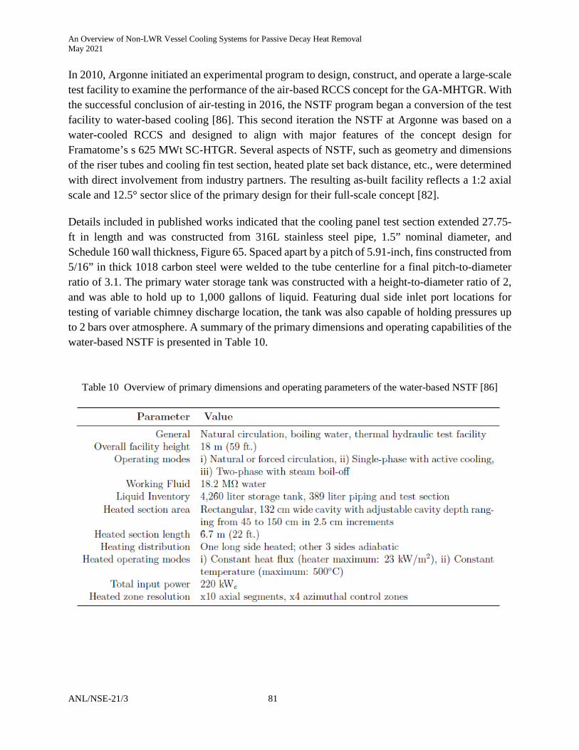
An Overview of Non-LWR Vessel Cooling Systems for Passive Decay Heat Removal May 2021
ANL/NSE-21/3 81
In 2010, Argonne initiated an experimental program to design, construct, and operate a large-scale test facility to examine the performance of the air-based RCCS concept for the GA-MHTGR. With the successful conclusion of air-testing in 2016, the NSTF program began a conversion of the test facility to water-based cooling [86]. This second iteration the NSTF at Argonne was based on a water-cooled RCCS and designed to align with major features of the concept design for Framatome’s s 625 MWt SC-HTGR. Several aspects of NSTF, such as geometry and dimensions of the riser tubes and cooling fin test section, heated plate set back distance, etc., were determined with direct involvement from industry partners. The resulting as-built facility reflects a 1:2 axial scale and 12.5° sector slice of the primary design for their full-scale concept [82].
Details included in published works indicated that the cooling panel test section extended 27.75-ft in length and was constructed from 316L stainless steel pipe, 1.5” nominal diameter, and Schedule 160 wall thickness, Figure 65. Spaced apart by a pitch of 5.91-inch, fins constructed from 5/16” in thick 1018 carbon steel were welded to the tube centerline for a final pitch-to-diameter ratio of 3.1. The primary water storage tank was constructed with a height-to-diameter ratio of 2, and was able to hold up to 1,000 gallons of liquid. Featuring dual side inlet port locations for testing of variable chimney discharge location, the tank was also capable of holding pressures up to 2 bars over atmosphere. A summary of the primary dimensions and operating capabilities of the water-based NSTF is presented in Table 10.
Table 10 Overview of primary dimensions and operating parameters of the water-based NSTF [86]

An Overview of Non-LWR Vessel Cooling Systems for Passive Decay Heat Removal May 2021
82 ANL/NSE-21/3
Figure 65: Installation of water cooling panel test section during construction of water NSTF [86]

An Overview of Non-LWR Vessel Cooling Systems for Passive Decay Heat Removal May 2021
ANL/NSE-21/3 83
A test plan has been identified in which attention was first given to the characterization of key design features, form and heat losses, nominal behavior, and repeatability. Tests performed in the single-phase flow regime evaluated steady-state behavior and heat removal performance. Of primary interest were areas of scaling verification, heat flux variation (integral levels and profiling), geometry, orificing, and investigations into the role of the inventory storage tank. Following continued testing with a transition to saturation with inventory loss due to boil-off will insight into design basis accident conditions, complex two-phase flow behavior, and expected levels of heat removal performance during accident conditions. Based on previously established QA processes during the air-based portion, the water-based NSTF testing method will continue to be conducted according to a controlled, traceable, and NQA-1 compliant program.
Based on recent results published by the water-based NSTF program [82], baseline testing was conducted that reflect conditions prototypic to the full-scale plant at both normal operation and design basis DLOFC conditions. These parameters translated to NSTF scaled thermal power levels of 34.4 kWt and 51.6 kWt, respectively. Additional tests were also conducted, which repeated baseline cases but included modification in decay heat load. At the time of this report, the water-based NSTF program at Argonne had entered its second year of test operations and begun to examine the behavior and performance of the water-based RCCS test facility at two-phase boiling flow conditions. Within the set of completed test cases, four were performed at standard two-phase baseline conditions to establish confidence in the test facility’s and operator’s ability to generate repeatable results. The remaining test that had been completed focused on studies of the role of system-level and coolant inventory.
Figure 66: Observed flow instabilities and phase regime mapping, boiling tests with water NSTF [87]

An Overview of Non-LWR Vessel Cooling Systems for Passive Decay Heat Removal May 2021
84 ANL/NSE-21/3
6.1.3. Hybrid RCCS Variations
Different RCCS concepts, e.g., air-based or water-based, with natural convection or forced convection of coolants, have been proposed, with each type exhibiting specific advantages and disadvantages. To overcome the disadvantages of the insufficient cooling capability of the air-based RCCS and the complexity of the water-based RCCS, Park et al., 2006 [63] and Oh et al., 2007 & 2009 [13], [14] proposed a new RCCS design that includes an air-cooled helical coil immersed in a water pool surrounding the reactor cavity.
The new RCCS concept, RCCS-SNU, mainly consists of a side water pool surrounding the reactor cavity, an upper water pool, cooling pipes in the water pools, and air supply systems, Figure 67. During an accident, the decay heat released from the reactor vessel is transferred to the side pool and upper pool through the cavity by thermal radiation and natural convection of the internal air. Part of the heat transferred to the water pool is taken away by the forced airflow through the cooling pipes. The rest of the heat will cause evaporation or boiling of the water pool. During both normal operation and accident conditions, the generated steam by evaporation or boiling in the water pool will be released to the ambient air through pressure relief valves set at 1.5 bar.
To experimentally investigate the thermal performance of the new RCCS concept, Park et al., 2006 [63] and Oh et al., 2007 & 2009 [13], [14] constructed a 1/10 scaled test facility based on the 265 MWt Pebble Bed Modular Reactor (PBMR) design, Figure 68 and Figure 69. Park et al., 2006 [63] performed separate effect tests on a test facility for the ¼ water pool of the RCCS-SNU, Figure 70, to investigate the heat transfer and pressure drop characteristics in the RCCS air tubes with U bends. The obtained temperature profiles along the elevation for both the pool water and forced air, along with the derived heat transfer coefficients were then used to validate the CFD code CFX5.7 and system modeling code MARS-GCR. It was found that CFX5.7 more accurately predicted both the forced air temperature and pool water temperature when compared with the experimental data, Figure 71. For the MARS-GCR, the heat transfer phenomenon by natural convection inside the water pool was accurately captured. However, the code did not accurately predict the heat transfer by forced convection of air inside the cooling pipe when using built-in Mori-Nakayama and Dittus-Boelter correlation, Figure 72. Instead, predictions were improved when new values for heat transfer coefficients, derived from the experimental test facility, were used instead.
These experiments investigated the various heat transfer phenomena in the new RCCS concept, including the natural convection of air inside the cavity, radiation through the cavity, the natural convection of water in the water pool, and the forced convection of air in the cooling pipes. The results were then used to develop the heat transfer correlations for the forced airflow inside the cooling pipes, which were ultimately 10% higher than the Mori-Nakamura correlation for helical coil, mainly due to the U-bend effect, Figure 73. To validate the U-bend effect, an Ansys CFXTM simulation was performed, which captured the centrifugal effect of the bend that shifts the maximum of the axial velocity toward the outer wall, Figure 74. The obtained experimental results

An Overview of Non-LWR Vessel Cooling Systems for Passive Decay Heat Removal May 2021
ANL/NSE-21/3 85
were also used to validate the RELAP5-3D code. The predicted reactor temperature was in reasonable agreement with the experimental results, demonstrating the code’s capability of simulating the RCCS system.
Figure 67: Illustration of the hybrid RCCS concept [14]

An Overview of Non-LWR Vessel Cooling Systems for Passive Decay Heat Removal May 2021
86 ANL/NSE-21/3
Figure 68: Schematic of the hybrid RCCS test facility [14]

An Overview of Non-LWR Vessel Cooling Systems for Passive Decay Heat Removal May 2021
ANL/NSE-21/3 87
Figure 69: Picture of the hybrid RCCS test facility [13] [14]

An Overview of Non-LWR Vessel Cooling Systems for Passive Decay Heat Removal May 2021
88 ANL/NSE-21/3
Figure 70: Schematic diagram of the test section for the separate effect test [63]

An Overview of Non-LWR Vessel Cooling Systems for Passive Decay Heat Removal May 2021
ANL/NSE-21/3 89
Figure 71: Comparison of the forced air temperature at pipe center (top) and pool water temperature
(bottom), CFX vs experiment [63]

An Overview of Non-LWR Vessel Cooling Systems for Passive Decay Heat Removal May 2021
90 ANL/NSE-21/3
Figure 72: Temperature distribution with Mori-Nakayama correlation (top), Dittus-Boelter correlation
(middle), and constant HTC from SET (bottom), MARS-GCR vs experiment [63]

An Overview of Non-LWR Vessel Cooling Systems for Passive Decay Heat Removal May 2021
ANL/NSE-21/3 91
Figure 73: Experimental results of the heat transfer coefficient for the RCCS cooping pipes [13][14]
Figure 74: Ansys CFX results showing the centrifugal effect of the cooling pipe bends [14]

An Overview of Non-LWR Vessel Cooling Systems for Passive Decay Heat Removal May 2021
92 ANL/NSE-21/3
Limited by the heat removal capacity of conventional air- or water-based RCCS concepts, the thermal power rating of a reactor aiming to use these systems for DHR often cannot exceed 1,000-1,300 MWt. To improve the performance of RCCS for larger HTGR concepts, a new analytical system was created to analyze various designs for their heat transfer characteristics and performance [15]. Using the design of a gas turbine modular helium reactor plant (GT-MHR) as a reference, a new passive decay heat removal system was developed, called liquid metal-filled decay heat removal system (LFDRS). As its name suggests, the LFDRS features a liquid metal-filled reactor cavity as shown in Figure 75, enabling a substantial increase in its heat removal capacity. Two different liquid metals, lead and tin, were selected to fill the gap between the reactor vessel and the enclosing container. Results from analytical simulations suggest that by using the LFDRS design, there can be about a 60% increase in the heat transfer rate, even without using radiation structures. With the new system, the heat removal capacity could be doubled, Table 11.
Figure 75: Schematic of the new design LFDRS [15]

An Overview of Non-LWR Vessel Cooling Systems for Passive Decay Heat Removal May 2021
ANL/NSE-21/3 93
Table 11. Heat transfer improvement by the new RCCS design approach, LFDRS [15]
Both HTGR and VHTR concepts operate with relatively high primary coolant temperatures and often adopt the concept of RCCS for removing heat from their reactor vessels. A typical RCCS includes forced water cooling which may become unavailable during accidents. Using the HTTR in Japan as an example, Takamatsu and Hu [16], [17] proposed a new highly efficient reactor cavity cooling system (RCCS) having passive safety features without any requirement of electricity and mechanical drive, Figure 76. The RCCS design consists of two continuous closed regions: one ex-reactor RPV region and another ambient air cooling region. In the new RCCS, the air absorbs heat released from the RPV and flows upward in the ducts. The cooling regions have two or three heat transfer areas, such as the interior, outside, and top surfaces. The RCCS uses a novel shape so that the heat released from the RPV can be removed efficiently with radiation and natural convection. Employing the air as the working fluid and the ambient air as the ultimate heat sink, the new RCCS design greatly reduces the possibility of losing the heat sink for decay heat removal. Therefore, HTGRs and VHTRs adopting the new RCCS design may be more likely to avoid total core meltdown. The simulation results from a commercial CFD code show that the temperature distribution of the RCCS is within the temperature limits of the structures and the heat released from the RPV could be removed safely even during a loss of coolant accident.
With the same novel RCCS design, Takamatsu et al., 2018 [18] continued to investigate the heat leakage due to the heat conduction through the RCCS wall. In the previous study [16], [17], the reported heat-removal rate was approximately 3 kW/m2. Under the assumption that the RCCS wall heat-transfer area can be doubled, a heat flux removed by the RCCS could also be doubled at an increased thermal reactor power level. Based on the novel RCCS design, Takamatsu et al., 2019 [19] compared an actual size RCCS and a downscaled heat-removal test facility. The authors changed the adiabatic boundary conditions and considered the heat dissipation effect from the RPV region to ground through the RCCS wall via heat conduction, improving the system’s heat-removal capability, Figure 77. Also, the authors investigated the effects of surface emissivity, which can potentially increase the capacity of RCCS to 7.0 kW/m2. The authors concluded that with the comparative methodology developed, the downscaled heat removal test facility is useful to provide the heat flux information on the actual size RCCS.

An Overview of Non-LWR Vessel Cooling Systems for Passive Decay Heat Removal May 2021
94 ANL/NSE-21/3
Figure 76: Temperature distribution of a new RCCS using novel shape [16]
Figure 77: Analytical model of the novel RCCS and the calculated temperature distribution [19]

An Overview of Non-LWR Vessel Cooling Systems for Passive Decay Heat Removal May 2021
ANL/NSE-21/3 95
6.2. Review of RVACS Previous Studies
Large-scale testing of an air-based RVACS system was performed at Argonne National Laboratory in the 1980s and resulted in several high-quality works published by the authors [51][37]. The description of their experimental plan indicates that their test facility, the Natural convection Shutdown heat removal Test Facility (NSTF), was reflective of a ½ scale model of the RVACS concept for the GE-Hitachi PRISM. The test assembly parameters, along with their performance map, Figure 78, suggest a high level of versatility in available testing conditions. Featuring a single chimney and extending over 85-ft in vertical elevation, this program reflects the largest known experimental test facility of an air-based RVACS concept, Figure 79. The experimental test facility aimed to accurately simulate prototypic reactor vessel temperatures, airflow patterns, and heat removal conditions that would exist for an RVACS system during normal and shutdown reactor operation. With many experimental control systems, the facility could operate in either constant guard vessel wall temperature up to 1,000°F or constant heat flux up to 2.0 kW/ft2. Unique to this facility is the use of highly prototypic guard vessel materials, which allowed them to accurately simulate the heat flux boundary condition, Figure 80. This plate was fabricated from SAE 1020 low carbon steel, with a "mill scale" oxidized surface condition so that its emissivity fell within the range 0.7 to 0.9 range [56]. The authors indicate that the ratio of guard vessel radius to duct wall air gap also matched those of prototypic values.
Figure 78: 1980's Argonne scaled RVACS test assembly parameters and available performance map [56]

An Overview of Non-LWR Vessel Cooling Systems for Passive Decay Heat Removal May 2021
96 ANL/NSE-21/3
Figure 79: Layout and dimensions of scaled RVACS test facility at Argonne [56]

An Overview of Non-LWR Vessel Cooling Systems for Passive Decay Heat Removal May 2021
ANL/NSE-21/3 97
Figure 80: Photograph of experimental test section from 1980’s RVACS testing at Argonne [51]

An Overview of Non-LWR Vessel Cooling Systems for Passive Decay Heat Removal May 2021
98 ANL/NSE-21/3
Previous scoping calculations have indicated the feasibility of the RVACS based air-cooled shutdown heat removal methods. However, uncertainties remain concerning the particular design concerning the width of the flow channel, the repeated-rib/fin arrangements and their locations, the rib/fin height, and the rib/fin spacing. In addition, the effects of the inlet air temperature, the pressure loss at the inlet and outlet, the stack height, the thermal loading, and material properties including surface emissivity on the performance of the air-cooling system were not clearly understood. Previous studies of turbulent flow and heat transfer in channels with or without fins/ribs have been restricted to the case of forced convection flow and the case of combined free and forced convection flow. One of the first objectives of Argonne-led optimization efforts was to conduct analytical and experimental research to evaluate the performance of the various design options.
Six different design options were identified for optimization, and these are shown schematically in Figure 81 [32]. In design option A (smooth wall option), the flow channel is simply the annulus space between the guard vessel and the cylindrical duct wall. The primary parameters are the height, H, of the gap between the two bounding walls and the ratio H/R, where R is the radius of the guard vessel. Generally, the curvature effect is negligible since R >> H. Hence, the flow channel may be approximated by the one formed between two parallel flat plates. This is the simplest design option among the others and is treated as the base case for comparison. Design option B involves the placement of repeated-rib roughness circumferentially on the bounding walls. The repeated ribs are employed to enhance heat transfer in the air-cooling system. Note that the roughness elements may be placed on either one or both surfaces. The primary parameters are the height, H, the pitch, p, and the shape of the roughness elements. In design options C, D, and E, vertically-spaced straight fins are employed to enhance the total heat transfer surface area. Design option C involves the placement of all of the fins on the guard-vessel side. The primary parameters are the fin height, H, the fin spacing, S, and the clearance, C, between the tips of the fins and the duct wall. Other parameters that would affect the performance of the system include the thickness and shape of the fins and the fin geometry (e.g., continuous fins vs. staggered fins). Design option D involves the placement of all the fins on the duct wall. The important parameters are the same as those for option C. Design option E is a combination of design options C and D. It involves the placement of half of the fins on the duct wall and the other half on the guard vessel, being arranged in an alternative manner. Design option F is a variation of design option E. It involves the simultaneous placement of short fins on both the guard vessel and the duct wall. Note that for a given sodium pool temperature, a higher heat transfer per unit area can be achieved for fins placed on the guard vessel rather than on the duct wall. This is because the guard-vessel temperature is always higher than the duct-wall temperature so that a higher rate of radiative and convective cooling can be achieved by using extended surfaces from the guard vessel. This, however, must be weighed against the disadvantages in fabrication cost, in-service inspection, and containment boundary complications associated with putting fins on the guard vessel.

An Overview of Non-LWR Vessel Cooling Systems for Passive Decay Heat Removal May 2021
ANL/NSE-21/3 99
Figure 81: Schematic representations of six designs [37]
General Electric was interested in Design Options A, B, and D and, therefore, the heat transfer characteristics of these options were analyzed [32]. The analysis found that repeated rib roughness provides some benefit to reducing reactor vessel temperatures provided that the ribs are smaller than 5 mm. For large ribs, reduced airflow effectively cancels the benefit of an increase in heat transfer coefficient. Placing the ribs on the guard vessel alone would not improve the performance compared to the case with ribs on both the guard vessel and the duct wall.
The analysis presented in [32] also provided useful guidance to the design of Argonne’s Shutdown Heat Removal Test Assembly which simulates experimentally the GE RVACS. The test assembly prototypically simulates a full-size vertical segment of the GE RVACS, the flow channel between the guard vessel and the duct wall. The test assembly includes sufficient instrumentation to determine local wall and air temperatures, velocity profiles, and heat flux rates at various elevations; from such recorded information the heat transport performance characteristics for chosen configurations can be evaluated. The primary objective of the Argonne RVACS program is to test theoretically optimized configurations to determine the local heat flux transport rates and associated convective heat transfer coefficients at various elevations, and evaluate their integral performance characteristics for the bounding range of shutdown decay heat removal conditions.

An Overview of Non-LWR Vessel Cooling Systems for Passive Decay Heat Removal May 2021
100 ANL/NSE-21/3
The effects of design parameters on the performance of the RVACS of a pool liquid-metal reactor (LMR) were also investigated by Tzanos et al. [37] [38] to optimize the system. The parameters considered include (a) stack height, (b) size of the airflow gap, (c) system pressure loss coefficient, (d) fins on the guard vessel or the baffle wall, and (e) roughness (in the form of repeated ribs) on the airflow channel walls. As a measure of the RVACS performance, they used the peak sodium pool temperature reached during the transient following a reactor scram from full power. To identify the most promising of these parameters, a parametric study was first performed with a simple lumped parameter model. The most promising configuration determined from this study for the 3500-MW (thermal) reference design was further analyzed with the SASSYS code. The airflow gap size was found to affect the RVACS performance more than variations in the stack height and system pressure loss. A reduction in the gap size from 0.15 to 0.05 m reduced the peak sodium pool temperature by 25 °C. The placement of fins on the guard vessel was more effective than on the baffle wall. Roughness on the airflow channel walls in the form of ribs improved the RVACS performance even further. Horizontal ribs having a 0.003-m height and a 0.015-m pitch gave the best performance. Depending on the equivalent primary system heat capacity, a reduction of 40 to 66°C was determined with the simple lumped parameter model. To obtain a more realistic measure of the improvement that can be achieved with the best-ribbed configuration, its performance was also analyzed with the SASSYS code. The optimum ribbed configuration reduced the peak hot pool temperature and the peak cladding temperature by 52°C (from 735 to 683°C and from 741 to 689°C, respectively). This reduction improves the margin between peak primary system temperatures and their safety-limiting values.

An Overview of Non-LWR Vessel Cooling Systems for Passive Decay Heat Removal May 2021
ANL/NSE-21/3 101
6.3. Breadth of Experimental Testing Efforts
The use of a natural circulating for shutdown heat removal was a key feature of the advanced liquid metal reactor concepts initiated in 1985 by DOE-selected vendors as a part of a competitive procurement process. From a range of vendors, the DOE selected GE to develop its innovative design concept aimed at improving safety, lowering plant costs, simplifying plant operation, reducing construction times, and most of all, enhancing the plant's ability to be successfully licensed. The reactor program at Argonne had been providing support to evaluate the feasibility of the design [32]. In particular, as part of the DOE R&D program that supported the development of this fast reactor concept, the NSTF was developed at Argonne to provide proof-of-concept data for the RVACS under prototypic natural convection flow, temperature, and heat flux conditions.
Originally built to study the air-side performance of the GE PRISM, the first NSTF facility at Argonne successfully provided experimental data during the later portion of the 1980s [32]. The last (on-record) test at the original NSTF was performed in November of 1988, after which the facility sat idle until 2010. The facility was then revisited as part of US DOE’s Generation IV initiative focused on developing advanced reactor concepts.
As part of the Department of Energy (DOE) road-mapping activities, the gas-cooled Very High Temperature Reactor (VHTR) was selected as the principal concept for hydrogen production and other process-heat applications such as district heating and potable water production. On this basis, the DOE has selected the VHTR for additional R&D with the ultimate goal of demonstrating emission-free electricity and hydrogen production with this advanced reactor concept. One of the key passive safety features of the VHTR is the potential for decay heat removal by a combination of natural convection and radiation across an interstitial air gap that separates the reactor vessel from either air-filled tubes or water-filled pipes. For either coolant, sufficient natural convection flow is calculated to develop through the tubes to keep fuel temperatures at acceptably low levels. Both the air- and water-cooled Reactor Cavity Cooling System (RCCS) designs contain many features that are similar to the Reactor Vessel Auxiliary Cooling System (RVACS) that was developed for the GE PRISM sodium-cooled fast reactor. Due to similarities between RVACS and the RCCS, VHTR R&D plans call for the utilization of the NSTF to provide RCCS model development and validation data, in addition to supporting design validation and optimization activities. In support of this effort, Argonne has been tasked with the development of engineering plans for mechanical and instrumentation modifications to NSTF to ensure that sufficiently detailed temperature, heat flux, velocity, and turbulence profiles are obtained to adequately qualify the codes under the expected RCCS operational ranges. Both air- and water-based system designs have been included in the planning process. For the water-based RCCS facility at Argonne, several features align with the conceptual design that has been publicly released for the Framatome 625 MWt SC-HTGR. The final assembly of the water NSTF will reflect a 1/2 axial scale and 12.5° sector slice of the primary design features of a full-scale RCCS concept. The design of the NSTF also retains all features common to a fundamental boiling water thermosiphon and is thus well

An Overview of Non-LWR Vessel Cooling Systems for Passive Decay Heat Removal May 2021
102 ANL/NSE-21/3
poised to provide necessary experimental data to advance a basic understanding of natural circulation phenomena and contribute to computer code validation.
Based on the GA MHTGR design, the University of Wisconsin-Madison experimental RCCS was developed as a collaborative effort with Argonne. Using water as the working fluid, the RCCS operates in passive mode during an accident condition, rejecting heat from the RPV to the atmosphere via a system of parallel water tubes and interlocking cooling panels that line the cavity walls. The placement of cooling panels allows for complete enclosure of the cavity, thus protecting the delicate concrete containment and ultimately providing an additional pathway for energy transfer to the water tubes by conduction. Since active cooling cannot be guaranteed under accident conditions, the water heats up, reaches saturation conditions, and subsequently boils.
For Pebble Bed High Modular Temperature Gas cooled Reactor (PBMHTGR), the INWA test facility in Frankfurt, Germany, was built to correspond to a 20° sector of a 200 MWt Siemens/KWU HTR modular pebble bed reactor design. The test facility was constructed with all details of a realistic vessel and cast iron and concrete composite structure with circumferential tendon reinforcement at a scale of 1:1. The height of the sector was chosen to be approximately 2 m—only a fraction of the total axial system extension. Therefore, natural circulation conditions in the embedded tubes had to be simulated accordingly by appropriate forced convection conditions.
To overcome the disadvantages of the insufficient cooling capability of the air-based RCCS and the complexity of the water-based RCCS, Oh et al., 2007 and 2009 [13], [14] proposed a new RCCS design that adopts an air-cooled helical coil immersed in a water pool surrounding the reactor cavity. To experimentally investigate the thermal performance of the new RCCS concept, the authors constructed a 1/10 scaled test facility based on the 265 MWt Pebble Bed Modular Reactor (PBMR) design.
A small-scale (1:23) water-cooled RCCS was built at Texas A&M University [26] to investigate the thermal-hydraulic phenomena taking place in the water-based RCCS during steady-state and transient conditions. Table 12 provides a summary of experimental testing capabilities available worldwide. To date, no experimental efforts have been made for RVACS or RCCS at scales larger than 1:2.

An Overview of Non-LWR Vessel Cooling Systems for Passive Decay Heat Removal May 2021
ANL/NSE-21/3 103
Table 12: Summary of known experimental efforts on RCCS and RVACS ex-vessel cooling systems for decay heat removal
DHR Concept
Prototype Reactor Test Facility Working
Fluid Peak Heat
Flux Heated Length
No. Channels Institution Year Ref.
RVACS GE PRISM NSTF (legacy) Air 21.5 kW/m2 6.7 m 1 Argonne 1986 [51]
RVACS LMFBR unnamed Air 10 kW/m2 3.5 m 1 CRIEPI 1991 [57]
RCCS GA-MHTGR unnamed Air 2.4 kW/m2 8.6 m 1 MIT 1991 [66]
RCCS PB-MHTGR INWA (legacy) Water unknown 2 m 1 Batelle Europe 1992 [23]
RCCS Siemens SANA/SANA-II Water unknown 1 m 4 Sinempelkamp 1992 [95]
RVACS FBR unnamed (legacy) Air ~15kW/m2† 2 m 1 Kawasaki 1993 [90]
RCCS HTGR, VHTR SCALE Air 7kW/m2 0.38 m 1 JAERI/Kyushu 2004 [94]
RCCS PMR200 NACEF Air 15 kW/m2 4.05 m 6 KAERI 2006 [80]
RCCS PBMR RCCS-SNU IET Air + Water 10 kW/m2† ~2 m† 6 KAERI 2006 [93]
RCCS PBMR unnamed Air + Water 10 kW/m2† 2 m 6 INL 2009 [14]
RCCS HTGR unnamed Water unknown 0.2 m 1 TAMU 2010 [67]
RCCS Hybrid unnamed Water 25 kW/m2 5 m 3 UW – Madison 2013 [89]
RCCS GA-MHTGR NSTF (modern) Air 21.5 kW/m2 6.7 m 12 Argonne 2016 [88]
RVACS PGSFR SINCRO-V Air unknown ~1.2 m 1 UNIST 2020 [91]
RVACS PGSFR SINCRO-3D Air unknown ~1.2 m† 1 UNIST 2020 [92] †estimated based on published information

An Overview of Non-LWR Vessel Cooling Systems for Passive Decay Heat Removal May 2021
104 ANL/NSE-21/3
6.4. Validation & Verification of Analytical and Modeling Tools
Due to technical challenges and high costs associated with large-scale experiments, analytical and modeling tools have been utilized for decades by the nuclear industry to support nuclear reactor design, operation, and safety analysis. These tools include the use of basic analytical calculations, 1-D and 2-D system-level codes, and 3-D Computation Fluid Dynamics (CFD) codes.
System-level codes (e.g., RELAP5, TRACE) assume a simplified model and provide the ability to analyze overall system behavior with minimal computation resources. Some system-level codes have also developed the capability to simulate the multidimensional phenomena involved in nuclear systems through pseudo-3-D modeling, such as the thermal-hydraulics code RELAP5-3D developed by Idaho National Laboratory (INL). To fully capture multidimensional phenomena and obtain a sound understanding of fundamental physics, many studies have incorporated additional modeling through the use of CFD or other high-fidelity codes. Due to the high cost of computational resources, CFD codes were historically only used for steady-state modeling or transient simulations of smaller regions. However, with continued development and recent advances in computing power, and increased development, CFD codes are increasingly being employed in nuclear reactor safety analyses. When used in support of more mature methods, these tools can provide additional analysis and detail of relevant phenomena.
For analysis of ex-vessel decay heat removal systems, a large number of system-level and CFD codes have been developed and used for modeling of RCCS and RVACS designs. In addition to their role of providing predictive capabilities, they also support facility design and instrumentation and understanding of physical phenomena observed in experimental testing. Furthermore, when qualified with benchmarked methods for verification and validation, these codes are a valuable tool in the licensing process. A high-level overview of these tools is provided in Table 13 and summarized below.
Conklin, 1990 [65] performed a dynamic simulation for the GA-MHTGR air-based RCCS using an in-house code that was later included in the MORECA code. Through a sensitivity study, it was found that the RCCS performance is highly dependent on the surface emissivity for both the reactor vessel and hot riser tubes, while the presence of steam in the cavity would cause higher vessel and fuel temperatures. Fu, 1991 [66] developed a computer code called RECENT (Reactor Cavity Energy Transfer) to calculate the integral heat removal capability of the GA-MHTGR RCCS from the reactor vessel to the ambient air, incorporating the Nusselt number and flow friction correlations obtained experimentally. Using the code, the author simulated a nominal case based on typical design parameters and predicted a reactor vessel temperature well below the design limit. Dilling et al., 1992 [65] performed a detailed analysis for the GA-MHTGR RCCS to simulate the decay heat removal process during a selected depressurized conduction cool down (DPCC) accident (SRDC-11), using both the TAC2D code and COMMIX-1A code. The simulation results confirm the adequacy of the RCCS heat removal capability to keep the reactor vessel temperatures within acceptable limits during the postulated accident. Kunitomi et al., 1996 [12] performed

An Overview of Non-LWR Vessel Cooling Systems for Passive Decay Heat Removal May 2021
ANL/NSE-21/3 105
analytical studies of the JAERI HTTR Water-based VCS performance under both depressurized and pressurized accidents with the thermal-hydraulics code TAC-NC, demonstrating the VCS’s capability of cooling the fuel and RPV below the design limits during both accident scenarios. Park et al., 2006 [63], Oh et al., 2007 & 2009 [13], [14] proposed a new hybrid air/water RCCS for HTGRs, and investigated its performance using the system modeling code MARS-GCR. The code was validated against the experimental data obtained from a 1/10 scale test facility. The code was found to accurately capture the heat transfer phenomenon by natural convection inside the water pool, but did not predict well the forced convection of air inside the cooling pipes unless in-house developed heat transfer coefficients were adopted. Kim et al., 2010 [70] performed a sensitivity study on the transient plant behavior during a postulated depressurized LOFC accident for a modified GT-MHR design, using the GAMMA+ code. The author investigated accident scenarios with the RCCS fully operational and another scenario with it fully failed. This study then examined the effect of a few parameters on the system performance, including the graphite properties, existence of the cavity wall insulation, and conductivities of the concrete and soil. Takada investigated the heat removal performance in the water-cooling panel system for the MHTGR for decay heat removal [25], using the numerical code THANPACST2 that was validated using the available experimental data. It was found that, when thermal radiation dominates the heat transfer from the vessel to the cooling panel, the model can closely simulate the pattern of the rising temperature profile. As part of the air-based NSTF testing program at Argonne, Hu et al., 2016 performed system-level modeling of the air-based NSTF facility using RELAP5-3D to assess the code’s capability in modeling a natural convection system like RCCS, as well as to support the experimental program. Using the experimental data, a RELAP5-3D model was developed that acutely captured the effects of outdoor air temperature, wind effects, building pressure, and the facility geometrical design features. With the completion of the air-based NSTF test program and transition to the water-based NSTF, system-level modeling of the new test facility was continued using both RELAP5 Mod3.3 and 3D.
Park et al., 2006 [63], Oh et al., 2007 & 2009 [13], [14] performed detailed simulation of a new RCCS concept, RCCS-SNU, using the CFX5.7 code. With a 1/10 scale separate effect test facility, the experimental data was used to validate the code, which was found to predict both the forced air temperature and pool water temperature well. To validate the U-bend effect, the authors also performed a simulation using the CFX code, which captured the centrifugal effect of the bend that shifts the maximum of the axial velocity toward the outer wall. Takamatsu and Hu [16], [17] proposed a new highly efficient reactor cavity cooling system (RCCS) having passive safety features without any requirement of electricity and mechanical drive, using the HTTR in Japan as an example. They performed modeling of this new concept using commercial code Star-CCM+, showing that the temperature distribution of the RCCS is within the temperature limits of the structures and the heat released from the RPV could be removed safely even during a loss of coolant accident (LOCA). Frisani et al., 2010 and 2011 [67], [68] developed a computational fluid dynamics (CFD) model to analyze heat exchange in RCCS using the commercial code STAR-CCM+. The developed model specifically simulated the 1/100 scale RCCS test facility constructed
An Overview of Non-LWR Vessel Cooling Systems for Passive Decay Heat Removal May 2021
106 ANL/NSE-21/3
at the Texas A&M University. A scaling analysis demonstrated that CFD model well simulated the physics inside the prototypic RCCS cavity region for a wide range of operating conditions under both water-cooled and air-cooled RCCS configurations. Lommers et al., 2014 [22] investigated the viability of the water-based RCCS concept for the Framatome SC-HTGR design, under the most challenging heat removal scenario, namely, a depressurized loss of forced circulation, or a depressurized conduction cooldown (DCC), using the commercial code Star-CD. The initial results, in terms of the fuel temperatures and other key component temperatures, confirmed the safety characteristics of the Framatome SC-HTGR concept, which provided a sound basis for further design development and optimization.

An Overview of Non-LWR Vessel Cooling Systems for Passive Decay Heat Removal May 2021
ANL/NSE-21/3 107
Table 13: Summary of known computational and modeling tools for RCCS and RVACS ex-vessel cooling systems for decay heat removal
Modeling Tool Code Dimension Developer Country Initial Release
Use in DHR analysis Concept Fluid Studies
RELAP5-3D 1D system INL / US NRC USA 1975 RCCS Air, Water [96] TAC2D 2D system General Atomics USA 1976 RCCS Air [65] COMMIX – 1A 3D system Argonne USA 1980 RVACS Air [51] COMMIX – 1A 3D system Argonne USA 1980 RCCS Air [65] FLUENT 3D system ANSYS, Inc. USA 1983 RCCS Water [118] TAC-NC 2D system JAERI Japan 1989 RCCS Water [12] MORECA 1D system ORNL USA 1991 RCCS Air [64] CERES unknown CRIEPI Japan 1991 RVACS Air [57] SAS4A/SASSYS-1 3D system Argonne USA 1991† RVACS Air [53] RECENT unknown MIT* USA 1991† RCCS Air [66] RELAP5/Mod3D pseudo 3D system INL / US DOE USA 1997 RCCS Air, Water [96] THANPACST2 3D system JAERI Japan 1997 RCCS Water [25] MARS-GCR 3D system* KAERI Korea 2003 RCCS Air, Water [93] Star-CCM+ 3D CFD CD-adapco USA 2004 RCCS Air, Water [96] Star-CCM+ 3D CFD CD-adapco USA 2004 RCCS Air, Water [67] CFX-5 3D CFD Ansys USA 2004 RCCS Air, Water [13] Star-CD 3D CFD CD-adapco USA 2004 RCCS Water [22] WCOBRA/TRAC – TF2 3D system Westinghouse USA 2011 RVACS Air [98] MELCOR 2D system SNL / US NRC USA 2016 RCCS Air, Water [97] SAM 1D transient Argonne USA 2017 RCCS Water [117] GAMMA+ 3D CFD KAERI Korea unknown RCCS Air, Water [80]
†estimated based on published information

An Overview of Non-LWR Vessel Cooling Systems for Passive Decay Heat Removal May 2021
108 ANL/NSE-21/3
7. Behavior during Off-Normal and Degraded Conditions
A large number of experimental and computational studies have been conducted to understand the behavior and predict the performance of various RCCS and RVACS type vessel cooling systems. In addition to normal operation, several of these studies included considerations for design basis accident scenarios to provide quantitative metrics for parameters such as cooling channel surface temperatures, flow rates, reactor core temperatures, heat removal capacity, etc. Of these, a subset continued their investigation into beyond design basis scenarios. A summary of these works and the major findings is provided below.
7.1. RCCS
7.1.1. Blockage of Riser Flow Channels
Testing performed on the modern, air-based RCCS of the NSTF at Argonne examined system response and heat removal performance with blocked riser channels [58]. Their test began by establishing steady-state operating conditions at the normal operating heat load, which defined a full-scale load of 700 kWt, or 26.16 kWt in the test facility, scaled ½ axially from the full-scale RCCS design for the GA-MHTGR. The authors initiated three stages of degraded operation at 16.6%, 33.3%, and 50% cooling channel blockage, which were accomplished by physically closing two, four, and then six riser channels, respectively, Figure 82.
Figure 82: Four stages of riser blockages in the air-based NSTF, red arrows indicate heated surface [58]

An Overview of Non-LWR Vessel Cooling Systems for Passive Decay Heat Removal May 2021
ANL/NSE-21/3 109
Each stage was allowed to reach stable, steady-state flow conditions for a minimum period of six hours. Time-averaged values were used to meet established acceptance criteria, which defined system parameters that did not vary more than 5% over the six hours. These criteria were verified with observations of online test data by the test operator (later confirmed by raw data processing), which showed a stable thermal energy balance within the heated test section for a period that did not change more than ±5% over a six-hour window. The results from this study are provided as the time history of the system flow rate, Figure 83, and percent reduction in flow rate with each new stage of riser blockage, Figure 84.
While the total system flow rate was reduced at each stage, the authors observed the facility’s performance to remain largely unaffected, as it continued to perform its heat removal function well. The heated plate temperature, representing the walls of an RPV, averaged 279°C for the normal, fully open operation, and only increased to 282, 288, and 292 °C at each respective stage, Table 14. These minor rises in RPV temperature suggest high confidence in the system’s ability to maintain high heat removal performance even in the event of blocked riser channels.
Figure 83: Time history of system flow rate with various blockage stages indicated [58]

An Overview of Non-LWR Vessel Cooling Systems for Passive Decay Heat Removal May 2021
110 ANL/NSE-21/3
Figure 84: Step change in flow rate as a function of riser blockage [58]
Table 14: Summary of air-based NSTF testing at various stages of degraded riser channel flow area [58]

An Overview of Non-LWR Vessel Cooling Systems for Passive Decay Heat Removal May 2021
ANL/NSE-21/3 111
7.1.2. Flow Path Short Circuit
Studies performed with the modern air-based NSTF at Argonne also examined the effect of a chimney “short-circuit”. In this scenario, a break occurs between adjacent ductwork that allows incoming cold air to by-pass the heated section and instead flows directly back into the exhaust stream [58]. For this test case, a variable damper valve was installed between adjacent ductwork, where one duct serves as the primary fresh air intake and the other as the exhaust discharge. By opening this valve, a short-circuit could be simulated within the test facility. Break areas of 33, 50, and 100% nominal single duct flow areas were studied, with a summary of the resulting system behavior provided in Table 15.
Table 15: System behavior with varying amounts of chimney short-circuit break areas [58]
Using local air velocity sensors positioned at the intake and exhaust ductwork, authors observed a significant portion of fresh air being diverted into the break area and short-circuiting directly into the exhaust. For a 33% break area, a total of 0.56 kg/s of originating fresh air entered the system, of which only 0.3 kg/s continued into the heated region. The remaining 0.26 kg/s was instead diverted directly back into the discharge exhaust, Table 16. The authors concluded that these breaks may severely degrade the heat removal performance of the air-based RCCS system, and could result in severe impacts to system temperatures.
Table 16: Split in air distribution across break and heated region [58]

An Overview of Non-LWR Vessel Cooling Systems for Passive Decay Heat Removal May 2021
112 ANL/NSE-21/3
7.1.3. Non-Air Gas Ingress
Testing on the modern air-based NSTF also examined the scenario of an operating air-cooled RCCS being subjected to a non-air gas ingress [77]. In the test case, their 1:2 scale air-based RCCS test facility was modified to allow a transition of the draft intake from normal ambient air, to draft intake from an open-top volume containing high purity argon. Testing began by establishing normal operation and allowing the facility to reach steady-state thermal-hydraulic flow conditions with natural air draft. The transition sequence was then initiated which simultaneously changed the inlet boundary from open-air to a pathway from the quiescent argon volume, Figure 85. This event caused 1,200-ft3 of the heavy gas, twice the internal volume of the total facility flow path, to be drawn into the inlet plenum and ingress into the heated riser standpipes.
The authors observed system flow rates that quickly fell to nearly zero in about ninety seconds after initiation of the argon ingress sequence and the facility experienced near-total flow stagnation for a period of approximately eighteen minutes. Due to the cessation of bulk fluid movement and subsequent failure of its heat removal function, fluid and structural temperatures began to rise sharply, Figure 86. After approximately eighteen minutes, fluid temperatures in the riser tubes rose to a level sufficient to allow re-establishment of buoyancy-driven system flow, and ultimately, recovery of facility operation to normal behavior after the argon volume was depleted from the system.
Figure 85: Sequence from air to argon by-pass testing performed on a 1:2 scale air-based RCCS [77]

An Overview of Non-LWR Vessel Cooling Systems for Passive Decay Heat Removal May 2021
ANL/NSE-21/3 113
Figure 86: Riser gas inlet and outlet temperatures of the NSTF with non-air gas ingress [77]

An Overview of Non-LWR Vessel Cooling Systems for Passive Decay Heat Removal May 2021
114 ANL/NSE-21/3
7.2. RVACS
The RVACS performance, as well as the behavior during several off-normal events, was studied by Boardman and Hunsbedt [47] for several events involving various degrees of RVACS air flow passage blockages. Several postulated events and scenarios considered beyond the design basis have been analyzed to illustrate the acceptable performance of the RVACS under unusual and severe conditions. The events include various degrees of RVACS air inlet and outlet flow area blockages and different reactor silo water flooding scenarios. Results from reference, normal operation are first presented, followed by finding of off-normal scenarios.
The ALMR plant has three redundant methods for shutdown heat removal, including a safety-grade RVACS which removes heat passively from the reactor containment vessel. The basic RVACS heat removal capability is self-regulating with the reactor temperature. Thus, the heat removal rate is only 0.9 MWt during normal operation temperature conditions (0.19% of the power produced) and increases to about 2.8 MWt at the higher reactor temperature experienced during an "RVACS only" transient in which both the condenser and ACS are not available. Transient analysis results for the basic RVACS event for nominal expected analysis assumptions and with clean heat transfer surfaces are given in Figure 87. The curve gives the average core sodium outlet temperature. The maximum average reactor core sodium outlet temperature reached is 607°C (1,125°F). The authors note that sodium and structural temperatures in most other regions of the reactor are considerably lower than the average core outlet temperature. The slight discontinuity in the curve at about 4 hours occurs when overflow starts at a hot pool temperature of 538°C (1,000°F). The discontinuity is slight because the performance of RVACS is excellent both with and without overflow.
Figure 87: Average core sodium outlet temperature for natural operating conditions [47]

An Overview of Non-LWR Vessel Cooling Systems for Passive Decay Heat Removal May 2021
ANL/NSE-21/3 115
7.2.1. Blockages of Air Inlets and Outlets
Various postulated RVACS air blockages at the air inlets and outlets (see Figure 26) have been considered with cases outlined in Table 17. It is seen that partial area blockages of the air inlets and outlets have small effects on the maximum average core sodium temperature reached during an RVACS transient. Thus, blocking each of the four air inlet openings 75% and each of the four air outlets also by 75% causes an increase in the maximum core outlet temperature of only 32°F (18°C). This illustrates the tolerance of RVACS to this type of postulated event. The main reason for the slight influence of area blockages at the air inlets and outlets is that their flow resistance is only 2.6% and 4.5%, respectively of the total RVACS airflow path resistance.
The effect of removing one or several RVACS air stacks from the system as a result of a postulated major external event is more pronounced than area blockage only. Previous works suggest that the stack portions of the inlet and outlet ducts (Figure 26) forming the airflow path constitute about 22% and 7% of the total airflow resistance, respectively. Removal of one or several of the stacks from service results in the total RVACS airflow being diverted to the remaining stack(s). The results for three postulated cases are given in Table 2. It is noted that removing one stack has only a slight effect and results in an increase of 7°F (4°C) in the core outlet temperature. However, the removal of three of the four stacks from service entirely increases the maximum core outlet temperature by 101°F (56°C). Although this increase is significant, the peak RVACS temperature is still well below the service level temperature limit of 1350°F (732°C).
Table 17: Average core sodium outlet temperature for natural operating conditions [47]

An Overview of Non-LWR Vessel Cooling Systems for Passive Decay Heat Removal May 2021
116 ANL/NSE-21/3
7.2.2. Complete Blockage of Air Inlets
More severe postulated events for an operating RVACS were evaluated including complete blockage of all air inlets while the four air outlets remain fully open. Nominally, four air outlet stacks are connected via the inlet plenum to the hot air riser annulus as indicated in Figure 26. Several assumptions subject to experimental verification were made in the analysis of this case. For example, the authors postulated that preferential downflow and upflow zones are created, as illustrated in Figure 88. In this so-called U-air flow model it is assumed that one half of the hot air riser annulus cross-sectional area is for downflow while the other half is for upflow and that cold air downflow is established in two of the four air outlet stacks while the hot air upflow is in the remaining two air outlet stacks.
The results of their transient analysis for this postulated case are summarized in Figure 89, which gives the average core outlet temperature. The maximum core sodium outlet temperature increases to 1168°F (631°C) which is well below the design basis temperature limit of 1250°F (677°C) for certain conditions, i.e. only 43°F (24°C) higher than that expected for the normal RVACS event.
Figure 88: U-air flow model for natural convection flow pattern in RVACS hot air riser with total
blockage of air inlets [47]

An Overview of Non-LWR Vessel Cooling Systems for Passive Decay Heat Removal May 2021
ANL/NSE-21/3 117
Figure 89: Average core sodium outlet temperature for blocked inlets case [47]
7.2.3. Complete Blockage of Air Outlets
The case of complete blockage of the RVACS air outlets while the air inlets remain open was also considered. Blocking of the outlet is technically less likely than blocking of the inlets because of the force of the air exiting at about 5 ft/sec (1.5 m/s) at a temperature of 190°F (87.8°C) during normal operating conditions. The U-flow model used for analysis purposes for the blocked outlet case is given in Figure 90. The analysis assumptions were similar to those used for the case of the blocked inlet, however, in this case, the recirculation pattern occurs in the cold air downcomer annulus and heat has to be transferred across the hot air riser gap primarily by thermal radiation (assumed in the present analysis). In addition, heat has to be conducted across the insulated collector cylinder. The results of the transient analysis show that the core outlet reaches 1393°F (756°C) which is on the limit of being acceptable. However, thermal insulation is required to protect the concrete silo during normal operation events. Unless the thermal insulation is designed to fail when high temperatures are reached, complete blocking of the air outlets would be unacceptable. However, even a small portion of airflow leaking through the outlets would result in increased cooling and an acceptable situation. It should also be pointed out that there is more than thirteen hours available to accomplish some degree of outlet unblocking before temperatures exceed acceptable structural limits.

An Overview of Non-LWR Vessel Cooling Systems for Passive Decay Heat Removal May 2021
118 ANL/NSE-21/3
Figure 90: U-air flow model for natural convection flow pattern in RVACS cold air downcomer with total blockage of air outlets [47]
7.2.4. Complete Blockage at Silo Bottom
Complete blockage of the RVACS air flow path at the bottom of the reactor silo just below the lower edge of the collector cylinder (Figure 26) is extremely unlikely. Postulated events that could produce such a blockage are a partial collapse of the concrete silo wall or a severe sand storm in which large quantities of sand enter the air inlets and are transported to the bottom of the silo. Even such events, however, are unlikely to block flow completely since the blockage materials, i.e. rubble or sand, possess some permeability to airflow. If such a blockage should occur, the U-flow models (Figure 88 and Figure 90) of cooling would be active in both the annuli of the hot air riser and the cold air downcomer. Thus, the analysis performed for the case of the blocked inlet [47] using the model of Figure 88 is applicable. However, there will also be some cooling in the cold air downcomer, resulting in slightly better performance for this case relative to the case of the blocked inlet. As a result of this expected slight performance improvement, the blocked silo bottom case was not completed.

An Overview of Non-LWR Vessel Cooling Systems for Passive Decay Heat Removal May 2021
ANL/NSE-21/3 119
7.2.5. Tolerance to Reactor Silo Water Seepage
The RVACS stacks are provided with weather caps to prevent significant amounts of precipitation from entering the system. However, if water finds its way into the RVACS by other means, for example, seepage of groundwater through the silo walls, precipitation through the inlet gratings, etc., it will collect at the bottom of the silo, as indicated in Figure 91. This trapped water will eventually be evaporated due to the heat generated inside the silo and carried out by the RVACS air. The rate of evaporation is dependent on the water and air temperatures, air velocity near the surface of the water, and air humidity. Assuming that the airflow rate through the RVACS remains constant, the air velocity decreases as the water level decreases, since the flow area increases. An analysis was performed with entering air, assumed to be at 70°F (21°C) and having a 20% relative humidity, being humidified by picking up water vapor in the silo before the air is discharged through the air outlets [47]. In this analysis, two cases were considered, with the first case assuming an initial mass of water to be deposited on the reactor floor and the subsequent seepage rate being zero. In the second case, various seepage rates were assumed with a small mass of water initially on the floor.
Results of the analysis for the first case show that the RVACS performance is not significantly affected when the silo is partially flooded with water. If the air passages are not blocked, the high temperatures inside the silo coupled with the high airflow rate contribute to the removal of more than 3,600 gallons (13.6m3), corresponding to an initial water level of 1 ft (0.304m), in less than 24 hours. The analysis results for the second case suggest that a water seepage rate through the concrete silo wall into the cavity of approximately 1.6 gallons per minute (GPM) (0.0001m3/s) can be accommodated on a steady-state basis without the water level ever reaching the containment vessel. When the floodwater reaches a higher level and comes in contact with the containment vessel, sufficient heat is transferred from the collector cylinder and containment vessel to boil the water pool. The rate of water removal in this mode increases significantly, and much higher seepage rates can be accommodated.

An Overview of Non-LWR Vessel Cooling Systems for Passive Decay Heat Removal May 2021
120 ANL/NSE-21/3
Figure 91: RVACS airflow path and configuration for flooding analysis [47]
Additional analysis was performed for the extremely unlikely event of an instantaneous, catastrophic complete flooding of the reactor cavity in which the complete air-flow path is filled with water. The results show that the containment and collector cylinders will experience thermal shocks as they are quenched by 70°F (21°F) water. The maximum rate of change of temperature for the containment vessel was about 1.2°F/sec (0.7°C/sec) which is acceptable from a structural point of view. The reactor vessel is insulated by the gas gap between the containment and reactor vessels and experiences no noticeable effects from the postulated flooding. Reactor sodium temperatures decrease quickly following reactor scram. Evaporation of water in contact with the steel structures would provide effective decay heat removal. For example, evaporation of about 14 GPM (0.0009m3/s) of water would remove 2 MWt under steady-state conditions.
In summary, based on the analytical analyses performed, Boardman and Hunsbedt [47] conclude that the RVACS performance is tolerant to several hypothetical accident conditions, including airflow blockages and flooding.

An Overview of Non-LWR Vessel Cooling Systems for Passive Decay Heat Removal May 2021
ANL/NSE-21/3 121
8. Evaluation of Reliability and Performance
8.1. System Longevity over Plant Lifetime
The ability of an ex-vessel VCS installation to maintain intended function throughout the 40- or 60-year life of a commercial reactor could be contingent on the corrosion and structural integrity of material components. Given an omission of moving parts for some concepts, maintenance efforts could be substantially reduced and limited to adequate material preparation and regular inspection. However, the choice of some designers to use carbon steel for cooling channels may present unique challenges in maintenance efforts.
The riser ducts installed within the modern air-based NSTF at Argonne were selected to match GA specifications and purchased new from domestic suppliers [59]. The riser ducts were fabricated from welded structural rectangular steel tubing, ASTM A 500 Gr. B. Newly installed, the tubes featured a dark grey color, smooth surfaces, and average emissivity of 0.62. Throughout the program’s 2,250 hours of active testing, average heat fluxes of 5.92 kW/m2 caused significant corrosion and the creation of loose rust particles, Figure 92. The induced aging on the surface and surface emissivity was measured to increase in a relatively short time scale, increasing to an average 0.78 after only 450 hours of test operations. This was concluded to occur by surface corrosion in the form of iron oxide (commonly known as rust). With continued exposure to high temperature and fresh humid air, this process would be perpetual, and, if left unmitigated, could impose severe complications to the structural integrity of the riser ducts. Furthermore, the introduction of rainwater, a consideration that is expected based on the designer's references to drain connections within the lower cold plenum, Figure 93, would further augment this process.
Figure 92: Rust collected from bottom of scaled air-based RCCS test facility over 100-day period [58]
Figure 93: Engineered drain of an air-based
RCCS for anticipated water ingress [81]

An Overview of Non-LWR Vessel Cooling Systems for Passive Decay Heat Removal May 2021
122 ANL/NSE-21/3
8.2. Meteorological Influences
For air-based ex-vessel cooling systems that rely on engineered chimney stacks to provide an intake of ambient air and discharge of heated exhaust, the influence of weather can play a major factor in influencing the behavior of airflow within the channels and cooling system. In extreme meteorological cases, conditions can create impairment of the heat removal performance. The specific role of weather stems primarily from ambient air temperatures, which influence buoyancy driving head, and ambient wind speeds, which influence conditions at the intake and chimney flow area. These influences were actively tested by an Argonne team with their 1:2 scale air-based RCCS test facility [58]. Published works indicated that they observed several test scenarios which experienced total disruption of system flow and inability to meet target objectives, either during steady-state periods or while attempting start-up of natural circulation flow. Other, milder influences included perturbations on the symmetry of exhaust flow, difficulty in achieving repeatability, and localized fluctuations in system behavior.
In general, wind flowing over the top of a chimney can increase draft by producing a driving pressure that assists in pulling air from the chimney. However, under different geometric configurations and wind directions, the wind can be averse to the chimney’s upward flow by creating positive pressure at the top of the chimney [79]. The wind blowing around a building produces a positive pressure zone on the windward side and a negative pressure zone on the downwind side. Variations in system performance were also observed to be partially attributed to changes in the building temperature. This effect can be described as follows: the driving pressure head of a natural circulation system is highly dependent on the density difference between the cold and hot segments. Given the non-linear relationship between density and temperature for an ideal air gas, the absolute inlet temperature plays a role, even for two systems with identical temperature differences. With higher absolute inlet temperatures, the Δρ/ΔT is reduced, which lowered the driving pressure head and reduced the overall efficiency of the stack effect, Figure 94.
Figure 94: Relationship between standard air temperature and density [79]

An Overview of Non-LWR Vessel Cooling Systems for Passive Decay Heat Removal May 2021
ANL/NSE-21/3 123
8.2.1. Ambient Air Temperature
Throughout the 33-month testing window of the modern air-based NSTF program at Argonne, researchers conducted periodic testing at a standard set of conditions to verify system repeatability and monitor potential long-term changes in the facility performance [58]. Given that the chimney ducts of the test facility were exposed to the ambient outdoor environment, regular testing identified strong influences of weather on the behavior of the facility. Each of these test cases was performed in an identical facility configuration (uniform power profile, full elevation discharge via vertical chimney stacks) and in such a manner that maintained an equal time-power history across the test procedure. Across their full testing window, the span of outdoor temperatures ranged from a low of -18.1 C during winter months to a high of +29.8 °C during summer months.
Examining trends across multiple repeat test cases, the authors observed a clear relationship between the heated section temperature rise and ambient (outdoor) temperature, Figure 95. With colder ambient temperatures there is an increase in the natural driving force that stems from differences in air densities, which in turn drives a higher system mass flow rate. For constant thermal powers, this requires the temperature rise to decrease. Though this behavior does not significantly change the integral performance, it is an important finding that should be considered when predicting the behavior of natural draft air-based VCS systems.
Figure 95: Relation between heated RCCS ΔT and ambient temperature in air-based NSFT [58]

An Overview of Non-LWR Vessel Cooling Systems for Passive Decay Heat Removal May 2021
124 ANL/NSE-21/3
8.2.2. Start-up Sensitivity
As part of the effort at Argonne to study the performance of a prototypic air-based RCCS, tests were also performed with an alternate chimney configuration that mimicked the airflow path of their reference full-scale concept for the GA-MHTGR design. The study names this configuration as “adjacent chimney”, due to their inlet and outlet flow paths extending adjacent to each other along the full height of the test facility. Compared to the reference configuration, this configuration not only introduced additional flow resistance along inlet ductwork, but it also exposed the fresh air intake to the ambient weather conditions. This created a heightened sensitivity to meteorological conditions and challenged some of the efforts toward establishing as-intended natural circulation flow.
With this configuration, the Argonne authors indicated that multiple attempts were sometimes required to complete the test objectives and meet the testing acceptance criteria [58]. During the early stages of one test scenario, the wind speeds were relatively calm and averaged 1 – 2 m/s. However, co-located weather instruments began to measure an increase in wind speeds throughout the day, eventually reaching sustained speeds of 12 m/s that extended through the early evening. In the face of periodic gusts, the facility was challenged in maintaining the as-intended flow path. These occasional wind perturbations induced system-wide oscillations with transient states of reverse flow that discharged heated air from the inlet of the heated test section. By later portions of the test, these oscillations sent high-temperature air (58 °C observed) into the inlet plenum, Figure 96, and shutdown procedures were enacted to protect the sensitive instrumentation. In addition to difficulties to the test operator, the impact of these wind-related perturbations had effects on the heat removal performance of the test facility When compared against the previous reference cases, elevated temperatures of the riser duct walls and RPV surface were observed. When plotting the riser wall temperatures during this challenged start-up scenario to previously successful test cases with calm wind speeds, the degraded performance, and elevated surface temperatures, is evident, Figure 96.
Figure 96: System wide reverse flow observed on air-based NSTF created elevated temperatures [58]

An Overview of Non-LWR Vessel Cooling Systems for Passive Decay Heat Removal May 2021
ANL/NSE-21/3 125
8.2.3. Wind Gusts, Air-RCCS Chimney
During testing performance on the air-based NSTF at Argonne [58], an approaching storm created an extreme change in ambient conditions. From a calm 3 m/s average wind speed, an approach of the storm gave way to sudden gusts exceeding 21 m/s. The transient impact onto the facility was profound, and dramatic perturbations in all system parameters were observed. Shown in Figure 97 is the response of the system flow rate during the wind gust. Furthermore, the coming storm could be first observed by a drop in ambient temperatures, which were reflected along the chimney stack wall thermocouples. The storm quickly passed and the system returned to its normal operating state.
In this specific instance, the authors observed only a transient perturbation from the wind gusts. However, it is important to note that the gusts observed is this instance originated from the western direction, perpendicular to the twin chimney stacks, thus approaching both uniformly. Had the wind gusts originated from a northern or southern direction, one chimney would have taken the full brunt of the wind while shielding the other from the strong gusts. The authors believe that this scenario would likely have created flow asymmetries in the test facility [58]. Lastly, the observed wind gusts occurred while the facility was operating at fully developed thermal and hydraulic flow conditions and high heat load. During start-up transients or low power operations, the facility was found to be more sensitive and would likely have seen stronger influences from the wind gusts.
Figure 97: Impact on the otherwise calm cool-down period after Run018 from a sudden wind gust [58]

An Overview of Non-LWR Vessel Cooling Systems for Passive Decay Heat Removal May 2021
126 ANL/NSE-21/3
8.2.4. Wind Gusts, RVACS Air Intake
The evaluation of the wind effects on the performance of the RVACS system is provided in a series of publications by Argonne and GE collaborators [39][40][41][42][43][44][45]. As described previously, the RVACS removes decay heat by natural circulation of air in the gap between the guard vessel and a duct wall surrounding the guard vessel. The reactor heat is released to the atmosphere through multiple stacks. The RVACS performance is a function of the pressure difference between the cooling air inlet and outlet, the air density variation along the flow path, and the pressure loss and heat transfer characteristics of this path. The pressure difference between the air inlet and outlet as well as the RVACS inlet temperature may be affected by wind speed and direction. The recirculation of air in the wake of a stack and the downward bend of a stack's hot plume by wind may affect its inlet temperature as well as that of its adjacent stacks. The objective of the research described in this section was to analyze the effects of wind on the performance of the RVACS of an advanced liquid-metal reactor (ALMR) design based on the PRISM concept.
To simplify the analysis, pressure distributions around the walls of the RVACS stacks were determined first by treating the stacks as solid closed structures, i.e., no cooling airflow was allowed in the stacks. These pressure distributions were used to qualitatively evaluate the effect of wind speed and direction, and stack design parameters on the pressure difference between stack inlets and outlet. Then, a more realistic analysis was performed with a configuration where the reactor heat source was simulated and airflow in the stacks was allowed. Wind speeds were varied from 2 to 27 m/s (5 to 60 mph). At the reference ALMR plant site, high winds of near 27 m/s (60 mph) are expected about once every 4 years. To account for the effect of wind direction, three wind directions were analyzed, 0, 90, and 180° with respect to a reference direction. In the more realistic analysis where the heat source was simulated, only two wind speeds, 13 and 27 m/s, and two wind directions (0 and 90°) were considered. The numerical computations were performed with the computer code COMMIX [46].
At the 1992 reference plant site of the PRISM ALMR, there are three power blocks, each having three reactor facilities with one reactor per facility. Each reactor facility has four RVACS stacks that serve one reactor. Two plant configurations were considered, designated here as plan 1 and plan 2. The plant layouts for plan 1 and plan 2 are shown in Figure 98. Note that the reactors are located underground. The major differences in the RVACS configuration of these two plant layouts are as follows: (a) in plan 1, a refueling enclosure (above ground) has been placed on top of the reactor and the RVACS stacks extend over the top of this enclosure, (b) in plan 1, the steam generator facility (above ground) is placed next to the refueling enclosure, (c) in plan 2, there is no permanent refueling enclosure, and the RVACS stacks extend only 6.8 m above ground level, and (d) in plan 2, the aboveground steam generator facility is located a substantial distance from the reactor facilities.
The qualitative evaluation (no airflow through the stacks) of wind effects on RVACS performance showed the following: in the configuration of plan 1, 0 and 180° winds should have a positive

An Overview of Non-LWR Vessel Cooling Systems for Passive Decay Heat Removal May 2021
ANL/NSE-21/3 127
effect on the performance of an RVACS with a two-inlet stack design. For a four-inlet stack design, the effect should be positive or nearly neutral. With a 90-deg wind, in both designs, some stacks would experience gains and some losses; the overall effect should be nearly neutral, but the four-inlet design would exhibit better performance than the two-inlet design. In the configuration of plan 2, a 0° wind should have a positive effect on the performance of the two inlet stacks and a positive or nearly zero effect on the performance of the four-inlet stacks. A 180° wind should have a nearly zero effect on the stacks of both designs. A 90° wind would have a negative impact on the performance of the two-inlet design and a positive or nearly zero impact on the four-inlet design. The difference in performance between a two-inlet and a four-inlet design seems to be more significant in the configuration of plan 2 than in that of plan 1. Finally, as would be expected, pressure differences between stack inlets and outlets varied approximately as the square of the wind speed.
The simplified analysis (no airflow through the stacks) indicated that wind in the 90° direction had the most adverse effect on RVACS performance. For this reason, in the more realistic analysis, where the heat source was simulated and airflow was allowed through the stacks, only 0° and 90° winds were considered. This more realistic analysis confirmed the previous conclusion that the 90° wind has the most adverse effect on RVACS performance, and in the configuration of plan 2, a four-inlet design would perform better than a two-inlet design. In a two-inlet design, for a 0° wind direction and a wind speed of 13 m/s, the airflow through the upwind stack increased (over the zero-wind velocity case) by 8% while that through the downwind stack decreased by 4%. For a 90° wind direction and the same wind speed, the airflow of the upwind stack decreased by 8% and that of the downwind stack by 4%. When two more inlets were added per stack (four inlet design), the airflow of the upwind stack increased by 0.5% while that of the downwind stack decreased by 2%. In a two-inlet design, the net effect on the airflow of a 90° and 27 m/s wind would be a reduction of approximately 15%, while in a four-inlet design the net effect would be nearly zero. A 15% reduction in the RVACS airflow would increase the peak cladding temperature by approximately 15°C. Since 90° is the wind direction that has the most adverse impact on RVACS performance and since in reality, the wind direction fluctuates around an average direction, the most adverse wind effect should be <15°C. The inlets of the downwind stacks are thermally affected by the outflow of the upwind stacks. However, the effect is small. For an air temperature rise of 164°C across the RVACS flow path, the maximum inlet temperature rise is approximately 5°C. This would raise the peak cladding temperature by approximately 1°C.

An Overview of Non-LWR Vessel Cooling Systems for Passive Decay Heat Removal May 2021
128 ANL/NSE-21/3
(a)
(b)
Figure 98: Configuration plan for wind study on RVACS [44]

An Overview of Non-LWR Vessel Cooling Systems for Passive Decay Heat Removal May 2021
ANL/NSE-21/3 129
8.3. Natural Circulation Stability
Due to the inherent nature of buoyancy-driven natural circulation loops, flow instabilities must be considered when designing and analyzing their behavior and heat removal performance. During natural convection-driven flow at stable steady-state condition, the driving forces (buoyancy) and losses (frictional) balance in equilibrium. However, when a perturbation occurs in the system, which can be introduced by any number of internal or external influences, this balance can be skewed and instabilities can arise and propagate. Such perturbations are readily introduced with air-based natural circulation systems that operate with low fluid temperature differentials, or water-based natural circulation systems that operate in boiling or two-phase flow conditions. Regardless of the choice of a working fluid, single-phase instabilities also exist in both air- and water-based systems.
8.3.1. Parallel Channels
Driven by safety requirements and the desire for redundancy, some vessel cooling designs feature multiple parallel paths for cooling fluid to travel through. This redundancy is often present in both the heated riser channels surrounding the reactor vessel and adiabatic downcomer and chimney ducts that connect the risers to the ultimate heat sink. Across the published works described in this report, a key difference between several of their scaled test facility and full-scale prototype concepts is the number of parallel channels within the overall network. Even large-scale test facilities, such as the ½ scale air-based NSTF at Argonne, contained only 12 risers out of the total 221 proposed by General Atomics. Similarly, their facility featured only two chimney paths, half of the total amount of the full-scale prototypic design.
Based on observations by the Argonne authors, the dual chimney configuration presented challenges in maintaining as-intended flow direction [58]. With four parallel chimney paths in a full-size design, there may be similar challenges in guaranteeing that a system will exhibit symmetric and equal flow across all ducts. An increase in air flow rate within a single chimney of a multi-chimney network will lower the pressure in that region of the system, thus increasing the driving buoyancy force and induced draft. With the increased draft, the single chimney would draw more air from the common plenum region, and possibly creating a self-perpetuating cycle that may create or otherwise exacerbate any flow asymmetry. Though working against a safety-based design philosophy and the desire for redundancy, any reduction in total available parallel paths would likely serve to increase the stability of natural draft, air-based VCS.
8.3.2. Air Cooled Vessel Cooling Systems
Air-based natural circulation systems benefit from the continuous availability of fresh coolant supplied by the natural atmosphere. Since the working fluid remains within a single-phase and experiences relatively minor density changes with temperature, these systems operate within a very fine balance of driving head and frictional losses. Buoyancy forces within a typical air-based

An Overview of Non-LWR Vessel Cooling Systems for Passive Decay Heat Removal May 2021
130 ANL/NSE-21/3
natural circulation system may only amount to 100 Pa or even less of driving pressure, a mere fraction of driving forces present in water-based systems. Thus, external factors need to introduce only minor perturbations to offset the buoyancy equilibrium and interrupt the natural circulation flow.
8.3.2.1. Start-up Sensitivity and Control of Weather Effects
Engineering controls (e.g. damper valves) may sometimes be necessary to reach desired stable flow conditions, however, to maintain a passive philosophy of any decay heat removal system, may otherwise be undesirable in a full-scale implementation. A subset of testing performed on the modern air-based NSTF examined the influence of full-length inlet and outlet ductworks in a parallel configuration [58]. This state mimicked one full-scale design, where inlet and outlet ducting are at a similar elevation above grade and extend nearly 92-feet to the reactor silo below. The addition of longer inlet ducting and thus higher resistance for incoming flow showed a destabilizing effect on the test facility behavior. The introduction of high frictional losses at the inlet, compounded with a transition from a ‘heated vertical pipe’ to a ‘heated U-loop’ geometry cause some system-wide reversals that were otherwise not observed in their normal duct configuration.
To avoid a repeat of these destabilized flow conditions, some testing was performed with the aid of time-dependent loafer valves along the chimney ductwork. A gradual opening over an extended period allowed the system to remain shielded from wind perturbations while the components underwent initial heat up and the system was allowed to establish the as-intended flow path. However, this required operator intervention conflicts with the overarching safety philosophy and would may not a feasible solution for a full-scale installation. Thus, it was of high interest to examine various anti-draft or draft-reducing weather caps for the NSTF chimney stacks to replace the actuator valves. Varying solutions for passive control were investigated and focused on a study for improving the design of the chimney cap installed on the exhausting ductwork. With unique requirements for a nuclear and safety-grade installation, a solution would be necessary that met the following criteria:
1. Fully passive (no human input or active power) 2. Prevent chimney reversals during start-up transients and low power conditions 3. Maintain the low frictional drop and not restrict airflow 4. Contain no moving parts
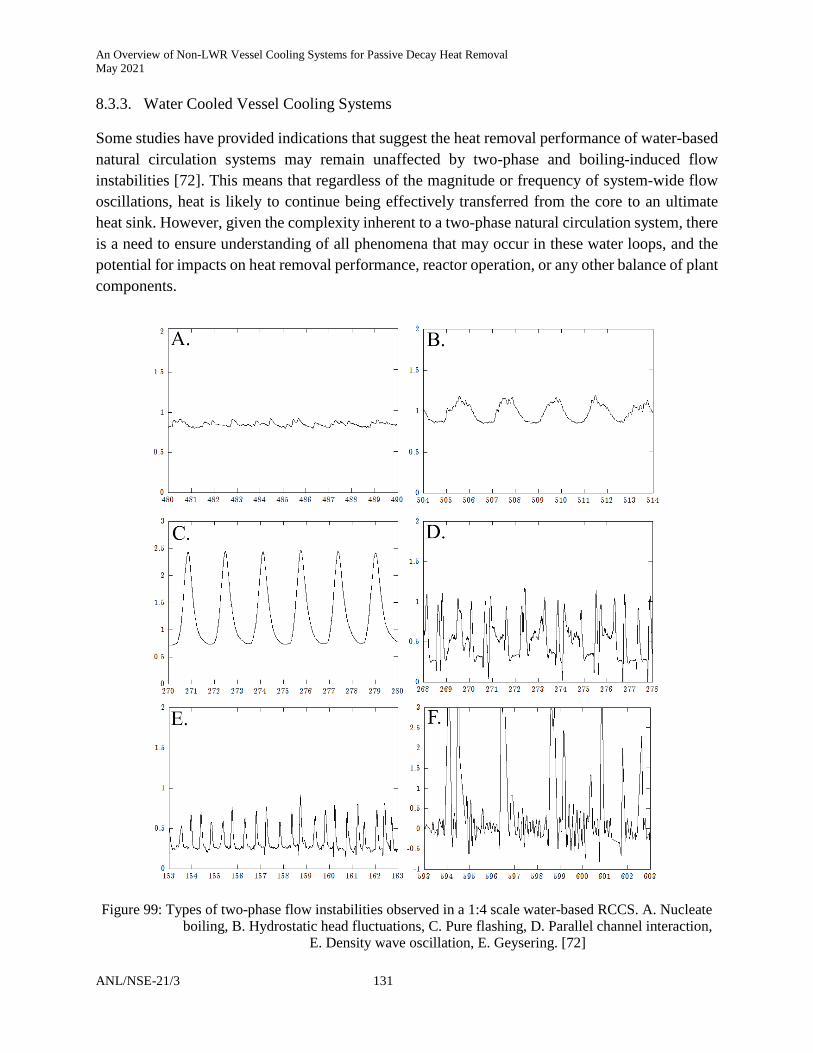
An Overview of Non-LWR Vessel Cooling Systems for Passive Decay Heat Removal May 2021
ANL/NSE-21/3 131
8.3.3. Water Cooled Vessel Cooling Systems
Some studies have provided indications that suggest the heat removal performance of water-based natural circulation systems may remain unaffected by two-phase and boiling-induced flow instabilities [72]. This means that regardless of the magnitude or frequency of system-wide flow oscillations, heat is likely to continue being effectively transferred from the core to an ultimate heat sink. However, given the complexity inherent to a two-phase natural circulation system, there is a need to ensure understanding of all phenomena that may occur in these water loops, and the potential for impacts on heat removal performance, reactor operation, or any other balance of plant components.
Figure 99: Types of two-phase flow instabilities observed in a 1:4 scale water-based RCCS. A. Nucleate
boiling, B. Hydrostatic head fluctuations, C. Pure flashing, D. Parallel channel interaction, E. Density wave oscillation, E. Geysering. [72]

An Overview of Non-LWR Vessel Cooling Systems for Passive Decay Heat Removal May 2021
132 ANL/NSE-21/3
8.3.3.1. Instability Mechanisms
Two-phase flow instabilities are not desirable in nuclear systems as they may cause forced mechanical vibrations and deteriorated heat transfers. Boure et al. [73] performed an extensive review of two-phase flow instabilities and classified the phenomena into different types based on their specific mechanisms and characteristics. For low-pressure boiling systems, typical types of instabilities that should be considered include natural circulation oscillations (also called thermal-hydraulic oscillations [74], or hydrostatic head fluctuations [75]), density wave oscillations (DWO), flow pattern transition instability, and geysering
In boiling systems, density wave oscillations are due to multiple regenerative feedbacks between the flow rate, vapor generation rate, and pressure drop [73]. Their phenomenon stems from a density difference between the inlet and outlet fluid states, which can trigger a delayed and alternating feedback from the subcooled liquid inertia and compressibility of the two-phase mixture, Figure 100. One characteristic of DWO is that the oscillation period is approximately 1.5 to 2 times of the fluid transit time in the channel [76]. Flow pattern transition instabilities have been postulated as occurring when the flow conditions are close to the point of transition between bubbly flow and annular flow. In bubbly-slug flow, a temporary increase in bubble population may change the flow pattern to annular flow with decreased pressure drop. The flow rate then increases, which may cause insufficient vapor generation, resulting in the flow pattern reverting to bubbly-slug flow. Lastly, geysering has been observed in a variety of closed-end vertical columns of liquid that are heated at the base. The process mainly consists of boiling delay, condensation or expulsion of vapor, and liquid return.
Figure 100: Mapping of stability regimes in 1:2 scaled water-RCCS with boiling [87]

An Overview of Non-LWR Vessel Cooling Systems for Passive Decay Heat Removal May 2021
ANL/NSE-21/3 133
8.3.3.2. Structural Vibrations from System Oscillations
Though heat removal performance has been shown to be relatively unaffected by system-wide oscillations, these instabilities do pose unique structural challenges for any future implementation. If large magnitude vibrations are sustained, piping supports, bolted mating assemblies, loosened securement hardware, etc. are at risk and must be engineered accordingly. Thus, there continues to be a strong interest in understanding the instability mechanism, which, at a minimum, will provide a shift away from uncertainty and into predictability. With continued development and further understanding, engineering controls or design features can then be incorporated to allow these systems to operate only in stable regimes. In an attempt to answer these questions, accelerometers were used to measure the structural vibrations present in an operating 1:2 scale water-based RCCS [82]. The authors indicate that the data is preliminary, and continued development may provide valuable insight into the stability and performance expected from a full-scale installation.
Figure 101: Structural vibration generated by boiling flow in 1:2 scale water-RCCS [87]
An Overview of Non-LWR Vessel Cooling Systems for Passive Decay Heat Removal May 2021
134 ANL/NSE-21/3
9. Summary
In support of the US NRC expanding capabilities for licensing of non-LWR reactor designs, a technical review of vessel cooling system (VCS) concepts for decay heat removal was performed. This review included previously published works available in the public domain, focusing on ex-vessel designs such as the Reactor Cavity Cooling System (RCCS), the Reactor Vessel Auxiliary Cooling System (RVACS), and hybrid iterations, using both air and water cooling to achieve their decay heat removal function. The findings from this review identified a large number of studies that have produced a wide breadth of experimental data and computational tools in support of various ex-vessel cooling designs. These studies, ranging from 1979 to the present day, have been led by both independent and collaborating institutions and resulted in the construction of several scaled experimental test facilities as well as the availability of numerous validated computational and analytical tools.
Based on an evaluation of the available data for the RCCS concept, many studies were identified that examined the role of design variations and operating conditions on the performance, heat removal function, and stability of these systems. These studies were conducted across several institutions and resulted in the construction of a broad set of test facilities across multiple scales, using both air- and water-based cooling designs. Computational and modeling tools included a diverse suite of analytical, system, and CFD level codes, which were used to overcome the limitations of experimental conditions and provided new predictive capabilities.
Based on an evaluation of the available data for the RVACS concept, many studies were identified which rigorously examined a large number of design variations and operating conditions, including their role on performance and heat removal function. The majority of these studies focused primarily on a computational and modeling approach. The availability of qualified experimental RVACS data, including comparisons across multiple scale test facilities, was limited.
Studies of air-based RCCS concepts observed stable and adequate levels of heat removal performance when operating under steady conditions at normal or design basis accident levels of decay heat load. Furthermore, the studies indicate that these systems can maintain their function during many off-normal scenarios, including blocked riser channels, transient chemical ingress, and asymmetries in heated profiles. However, under start-up, low-power, or strong wind conditions, some studies observed natural circulation phenomena that challenged the system’s ability to maintain symmetric flow within parallel channels. Thus, authors suggest that some natural draft air-based cooling systems may require the use of engineering controls (e.g. damper valves, shielded weather caps, etc.) to achieve or maintain stable flow paths.
Studies of RCCS systems that used water-based cooling observed a more stable response to external factors that readily degraded the operation of air-based concepts. However, these water-based designs rely on a finite supply of cooling inventory that must be replenished during extended accident scenarios. For systems that extend their operation into a boiling flow regime, they exhibit

An Overview of Non-LWR Vessel Cooling Systems for Passive Decay Heat Removal May 2021
ANL/NSE-21/3 135
unique sensitivity to complex two-phase flow phenomena, which may induce large amplitude flow oscillations and create vibration concerns for structural components. These instability modes were observed across many of the studies that operated at atmospheric pressures, but gaps remain in identifying definitive methods to suppress or mitigate the oscillations.
Studies that examined the capacity and heat removal performance of RVACS indicate that a high level of reliability and heat removal function can be expected during normal, accident, and degraded operating conditions. Analysis of the RVACS performance during unique off-normal scenarios, including partial and total blockage of air inlet and outlets, flooding, etc., yielded results that further support the system's high tolerance and robust function. However, these studies identified the need for additional experimental information about the air-side flow distribution, which authors indicate are necessary to verify the adequacy of the models used to represent these extreme scenarios. Assessment of current and past experimental data produced for the RVACS design suggests a gap in the availability of multiple-scale test facilities that are similarly designed and share features common to a full prototypic concept.

An Overview of Non-LWR Vessel Cooling Systems for Passive Decay Heat Removal May 2021
136 ANL/NSE-21/3
References
[1] International Atomic Energy Agency, 1994. Decay heat removal and heat transfer under normal and accident conditions in gas cooled reactors (No. IAEA-TECDOC-757). International Atomic Energy Agency, Vienna, Austria.
[2] International Atomic Energy Agency, 2000. Heat Transport and Afterheat Removal for Gas Cooled Reactors Under Accident Conditions (No. IAEA-TECDOC-1163). International Atomic Energy Agency, Vienna, Austria.
[3] Flanagan, G., Fanning, T., Sofu, T., Sodium-cooled Fast Reactor (SFR) Technology and Safety Overview, Presented at Office of Nuclear Energy, US DOE, February 18, 2005, Washington DC.
[4] Preliminary Safety Information Document for the Standard MHTGR (No. HTGR-86-024), 1992.
[5] US Nuclear Regulatory Commission, 2017. Quality Assurance Program Criteria (Design and Construction), Reg. Guide 1.28, Rev. 5.
[6] Lommers, L., Shahrokhi, F., Iii, J.M., Southworth, F., 2014. AREVA Modular Steam Cycle – High Temperature Gas-Cooled Reactor Development Progress 10.
[7] Tzanos, C.P., Farmer, M.T., Division, N.E., 2006. Feasibility study for use of the natural convection shutdown heat removal test facility (NSTF) for VHTR water-cooled RCCS shutdown. ANL-GenIV-079. Argonne National Laboratory
[8] Ishii, M., Ravankar, S.T., Dowlati, R., 1996. Scientific design of Purdue University Multi-Dimensional Integral Test Assembly (PUMA) for GE SBWR (No. NUREG/CR--6309, PU-NE--94/1, 220555).
[9] RCCS Designer Input Report, Technical Data Record, Document No.: 12-9239789-000, AREVA.
[10] L.J. Lommers, F. Shahrokhi, J.A. Mayer III, F.H. Southworth, AREVA HTR Concept for Near-Term Deployment, Nuclear Engineering and Design, v251, p.292, 2012.
[11] NGNP Industry Alliance, Next Generation Nuclear Reactor Design Selected for Safety and Efficiency, http://www.ngnpalliance.org/ index.php/news, February 15, 2012.
[12] Kunitomi, K., Nakagawa, S., Shinozaki, M., 1996. Passive heat removal by vessel cooling system of HTTR during no forced cooling accidents. Nuclear engineering and design 166, 179–190.
[13] Oh, C., Davis, C., Park, G.C., 2007. RCCS Experiments and Validation for High Temperature Gas-Cooled Reactor. Presented at the The 12th International Topical Meeting on Nuclear Reactor Thermal Hydraulics, NURETH-12, Pittsburgh, Pennsylvania, p. 14.
[14] Oh, C.H., Park, G.C., Davis, C., 2009. RCCS Experiments and Validation for High-Temperature Gas-Cooled Reactor. Nuclear Technology 167, 107–117.
[15] Sim Yoon Sub, Park Rae Young, Kim Seyun, 2007, Development of a new decay heat removal system for a high temperature gas-cooled reactor, Annals of Nuclear Energy 34 (2007) 803–812.

An Overview of Non-LWR Vessel Cooling Systems for Passive Decay Heat Removal May 2021
ANL/NSE-21/3 137
[16] Takamatsu, K., Hu, R., 2014. New Reactor Cavity Cooling System Using Novel Shape for HTGRs and VHTRs. Presented at the The 10th International Topical Meeting on Nuclear Thermal-Hydraulics, Operation and Safety (NUTHOS-10), Okinawa, Japan, p. 11.
[17] Takamatsu, Kuniyoshi, Rui Hu, 2015, New reactor cavity cooling system having passive safety features using novel shape for HTGRs and VHTRs, Annals of Nuclear Energy 77 (2015) 165–171.
[18] Takamatsu, Kuniyoshi, Tatsuya Matsumoto, Wei Liu, Koji Morita, 2018, Improvement of heat-removal capability using heat conduction on a novel reactor cavity cooling system (RCCS) design with passive safety features through radiation and natural convection, Annals of Nuclear Energy 122 (2018) 201–206.
[19] Takamatsu, Kuniyoshi, Tatsuya Matsumoto, Wei Liu, Koji Morita, 2019, Comparative methodology between actual RCCS and downscaled heat-removal test facility, Annals of Nuclear Energy 133 (2019) 830–836.
[20] Kunitomi, K., Shinozaki, M., Kodama, H., Yamamoto, M., Hontani, K., 1996. Design and Fabrication of the Reactor Vessel Cooling System (VCS) in HTTR, in: Proceedings of The 3rd JAERI Symposium on HTGR Technologies. Presented at the The 3rd JAERI symposium on HTGR technologies, Japan, pp. 322–337.
[21] Akio Saikusa, Kazuhiko Kunitomi & Shusaku Shiozawa, 1997, Advanced Vessel Cooling System Concept for High-Temperature Gas-Cooled Reactors, Nuclear Technology, 118:2, 89-96.
[22] Lommers, L.J., Mays, B.E., Shahrokhi, F., 2014. Passive heat removal impact on AREVA HTR design. Nuclear Engineering and Design, SI : HTR 2012 271, 569–577.
[23] Kugeler, K., Sappok, M., Beine, B., Wolf, L., 1992. Development of an Inactive Heat Removal System for High Temperature Reactors, in: Proceedings of a Specialists Meeting Held in Juelich, Germany. Presented at the Specialists meeting on decay heat removal and heat transfer under normal and accident conditions in gas cooled reactors, Juelich, Germany, pp. 131–139.
[24] Saikusa, A., Nakagawa, S., Fujimoto, N., Tachibana, Y., Iyoku, T., 2003. Data on Test Results of Vessel Cooling Systems of High Temperature Engineering Test Reactors (No. JAERI-DATA/CODE--2002-027). Japan Atomic Energy Research Institute, Tokyo, Japan.
[25] Takada, Shoji, 2004, Research and development on passive cooling system, Nuclear Engineering and Design 233 (2004) 185–195.
[26] Vaghetto, Rodolfo, Yassin A. Hassan, 2014, Experimental Investigation of a Scaled Water Cooled Reactor Cavity Cooling System, Nuclear Technology, Vol. 187.
[27] Carulec, B., LoPinto, P., ASTRID Safety Approach and Safety Features, 5th IAEA GIF Workshop of Safety of SFR, June 23-24, 2015, Vienna, Austria.
[28] Cinotti, L., and Corsini, G., A proposal for enhancing the primary coolant circulation in an ADS, unpublished
[29] Powell, D., PRISM Heat Removal Safety Systems, 5th IAEA GIF Workshop of Safety of SFR, June 23-24, 2015, Vienna, Austria.

An Overview of Non-LWR Vessel Cooling Systems for Passive Decay Heat Removal May 2021
138 ANL/NSE-21/3
[30] Triplett, B.S., Loewen, E.P., Dooies, B.J., 2012. PRISM: A Competitive Small Modular Sodium-Cooled Reactor. Nuclear Technology 178, 186–200.
[31] Johnson, R.A., Golan, S., Guenther, E., 1988. SAFR, an economic, inherently safe liquid metal reactor. Nuclear Engineering and Design 109, 87–95
[32] It’s Time for the United States to Demonstrate Advanced Reactors [WWW Document], n.d. . Energy.gov. URL https://www.energy.gov/ne/articles/it-s-time-united-states-demonstrate-advanced-reactors-0 (accessed 02/10/21).
[33] Forsberg, C., 2005. The advanced high-temperature reactor: High-temperature fuel, liquid salt coolant, liquid-metal-reactor plant. Progress in Nuclear Energy 47, 32–43.
[34] Forsberg, C.W., June 4–8, 20062006. Alternative Passive Decay-Heat Systems for the Advanced High-Temperature Reactor, in: Proceedings of ICAPP ’06. Presented at the 2006 International Congress on Advances in Nuclear Power Plants (ICAPP ’06), Reno, Nevada, p. 13.
[35] LeBlanc, D., 2016. An Overview of the Integral Molten Salt Reactor. Presentation to ORNL MSR Workshop 5th Oct 2016
[36] International Atomic Energy, 2013. Benchmark Analyses on the Natural Circulation Test Performed During the PHENIX End-of-Life Experiments. Final Report of a Co-ordinated Research Project 2008-2011 (No. IAEA-TECDOC--1703). International Atomic Energy Agency.
[37] Chawla, T.C., Cheung, F.B., Stewart, R.R., Pedersen, D.R., Tessier, J.H., Webb, R.L., Haupt, H.J., Anderson, T.T., Johanson, E.W., August, C., Pavlik, J.R., 1986. Modeling of the Air-Side Performance of the RVACS Shutdown Heat Removal System - Status of Experimental Program (No. ANL-PRISM-8). Argonne National Lab., IL (USA), Argonne, Illinois.
[38] Tzanos, C.P., Tessier, J.H., Pedersen, D.R., 1991. An Optimization Study for the Reactor Vessel Auxiliary Cooling System of a Pool Liquid-Metal Reactor. Nuclear Technology 94, 68–79.
[39] Tzanos, C., 1995. Wind effects on RVACS performance, in: Transactions of the American Nuclear Society. Presented at the 1995 Annual Meeting of the American Nuclear Society, Philadelphia, Pennsylvania, pp. 232–234.
[40] Tzanos, C., Hunsbedt, A., 1994. Impact of wind on RVACS performance. Presented at the 11th topical meeting on the technology of fusion energy.
[41] Tzanos, C.P., 1993. Predictions of RVACS Sensitivity to Wind Effects via COMMIX Calculations (No. ANL-IFR--181). Argonne, Illinois.
[42] Tzanos, C.P., Hunsbedt, A., 1993. Predictions of wind effects on RVACs performance. Transactions of the American Nuclear Society 69, 265–267.
[43] Tzanos, C.P., Pedersen, D.R., 1991. Analysis of DRACS and DRACS-RVACS decay heat removal experiments. Nuclear Technology 95:3.
[44] Tzanos, C.P., Hunsbedt, A., 1996. Wind Effects on the Performance of the Reactor Vessel Auxiliary Cooling System. Nuclear Technology 113, 249–267.

An Overview of Non-LWR Vessel Cooling Systems for Passive Decay Heat Removal May 2021
ANL/NSE-21/3 139
[45] Tzanos, C.P., 1997. Impact of Wind Velocity on the Performance of the RVACS Decay Heat Removal System. Nuclear Technology 119, 1–10.
[46] Blomquist, R.N., Garner, P.L., and E.M. Gelbard, 1991. COMMIX-1AR/P: A Three-Dimensional Transient Single-Phase Computer Program for Thermal Hydraulic Analysis of Single and Multicomponent Systems. Vol. 1: Equations and Numerics," ANL-90/45, Argonne National Laboratory
[47] Boardman, C.E., Hunsbedt, A., 1991. Performance of ALMR passive decay heat removal system. Presented at the IAEA-IWGFR specialists’ meeting on passive and active safety features of LMFRs, PNC, JAPAN, pp. 113–120.
[48] Rodenburg, M.A., Terrestrial Energy Leading the Way to a Bright Energy Future, SAMOFAR, Delft, July 2019.
[49] Wu, G., Jin, M., Chen, J., Bai, Y., Wu, Y., 2015. Assessment of RVACS performance for small size lead-cooled fast reactor. Annals of Nuclear Energy 77, 310–317. h
[50] Cinotti, L & Smith, Craig & Sienicki, James & Ait Abderrahim, Hamid & Benamati, G & Locatelli, G & Monti, Stefano & Wider, H & Struwe, D & Orden, A & Hwang, I. (2007). The potential of the LFR and the ELSY project. 10.1051/rgn/20074030.
[51] Anderson, T.T., August, C., Carson, N.J., Despe, O.D., Haupt, H.J., Heineman, J.B., Kraimer, M.R., Lottes, P.A., Myers, H.J., Pavlik, J.R., Pedersen, D.R., Pokorny, G.J., Stewart, R.R., Tessier, J.H., 1987. Air-Side Performance of RVACS/RACS -- Description of the Natural Convection Shutdown Heat Removal Test Facility and Supporting Analysis (No. ANL-PRISM-41). Argonne National Lab., IL (USA), Argonne, Illinois.
[52] Berglund, R.C., Tippets, F.E., Salerno, L.N., 1989. PRISM: A Safe, Economic, and Testable Liquid-Metal Fast Breeder Reactor Plant. Nuclear Technology 86, 22–29.
[53] Dunn, F.E., 1987. Validation of the RVACS (Reactor Vessel Auxiliary Cooling System)/RACS (Reactor Air Cooling System) model in SASSYS-1, in: Transactions of the American Nuclear Society. Presented at the 1987 Winter Meeting of the American Nuclear Society, Los Angeles, California, pp. 723–724.
[54] Dunn, F.E., 1987. SASSYS-1 modelling of RVACS [Reactor Vessel Auxiliary Cooling System]/RACS [Reactor Air Cooling System] heat removal in an LMR [Liquid Metal Reactor], in: Transactions of the American Nuclear Society. Presented at the 1987 Winter Meeting of the American Nuclear Society, Los Angeles, California, p. 22.
[55] Salerno, L.N., Berglund, R.C., Gyorey, G.L., Tippets, F.E., Tschamper, P.M., 1988. Prism concept, modular LMR reactors. Nuclear Engineering and Design 109, 79–86
[56] Stewart, R.R., Heineman, J.B., Haupt, H.J., Kraimer, M.R., Tessier, J.H., Lottes, P.A., 1987. Experiment Plan for the RVACS/RACS Air-Side Full-Scale Segment Tests in the ANL Natural Convection Shutdown Heat Removal Test Facility (No. ANL-PRISM-42). Argonne National Lab., IL (USA), Argonne, Illinois.

An Overview of Non-LWR Vessel Cooling Systems for Passive Decay Heat Removal May 2021
140 ANL/NSE-21/3
[57] Nishi, Y., Kinoshita, I., 1991. Study on Decay Heat Removal Capability of Reactor Vessel Auxiliary Cooling System. Presented at the IAEA-IWGFR specialists’ meeting on passive and active safety features of LMFRs, PNC, JAPAN, pp. 125–131.
[58] Lisowski, D., Lee, T., et al., 2016. Final Project Report on RCCS Testing with the Air-based Natural convection Shutdown heat removal Test Facility, ANL-ART-47, Argonne National Laboratory
[59] Lisowski, D., Farmer, M. T., et al., 2014. Design Report for the 1/2 Scale Air-Cooled RCCS Tests in the Natural convection Shutdown heat removal Test Facility (NSTF), ANL-SMR- 8 Argonne National Laboratory
[60] Bowers, H., 2017. X-energy and the Xe-100. Proc of 2017 ANS Annual Meeting. Presented at the American Nuclear Society, Washington, DC.
[61] Golovko, V.F., Kiryushin, A.I., Kodochigov, N.G., & Kuzavkov, N.G. (1996). State of HTGR development in Russia (IAEA-TECDOC-899). International Atomic Energy Agency (IAEA)
[62] Roberto, T.D., Lapa, C.M.F., Alvim, A.C.M., 2020. Scaling Analysis of Reactor Cavity Cooling System in HTR. Nuclear Technology 206, 527–543.
[63] Goon-Cherl, P., Yun-Je, C., Hyoungkyu, C., 2006. Assessment of a new design for a reactor cavity cooling system in a very high temperature gas-cooled reactor. Nuclear Engineering and Technology 38.
[64] Conklin, J.C., 1990. Modeling and Performance of the MHTGR Reactor Cavity Cooling System (No. NUREG/CR--5514). Oak Ridge National Lab. (ORNL), Oak Ridge, TN (United States).
[65] Dilling, D.A., Berkoe, J.M., Ghose, S.K., 1992. Modeling and Analysis of the Heat Transfer from the MHTGR Core Through a Steel Reactor Vessel to the Reactor Cavity Cooling System, in: Proceedings of a Specialists Meeting Held in Juelich, Germany. Presented at the Specialists meeting on decay heat removal and heat transfer under normal and accident conditions in gas cooled reactors, Juelich, Germany, pp. 111–116.
[66] Fu, G., 1991. Experimental and analytic evaluation of gas-cooled reactor cavity cooling system performance (Thesis). Massachusetts Institute of Technology, Cambridge, Massachusetts.
[67] Frisani, A., 2010. Analysis of the Reactor Cavity Cooling System for Very High Temperature Gas-Cooled Reactors Using Computational Fluid Dynamics Tools. Texas A&M University, College Station, Texas.
[68] Frisani, A., Hassan, Y.A., Ugaz, V.M., 2011. Computational Fluid Dynamics Analysis of Very High Temperature Gas-Cooled Reactor Cavity Cooling System. Nuclear Technology 176, 238–259
[69] Corradini, M., Anderson, M., Hassan, Y., Tokuhiro, A., 2013. Experimental Studies of NGNP Reactor Cavity Cooling System with Water (No. NEUP--Project-09-781, 1063993).
[70] Kim, S., Tak, N.-I., Lim, H.-S., Ha, S.-J., 2010. Sensitivity study on depressurized LOFC accidents with failure of RCCS in a modular gas-cooled reactor. Annals of Nuclear Energy 37, 664–671.

An Overview of Non-LWR Vessel Cooling Systems for Passive Decay Heat Removal May 2021
ANL/NSE-21/3 141
[71] Beine, B., Kaminski, V., Von Lensa, W., 1991. Integrated design of prestressed cast-iron pressure vessel and passive heat removal system for the reactor cell of a 200 mwth modular reactor. Energy, High-temperature Helium Gas-cooled Nuclear reactors: Past Experience Current Status and Future Prospects 16, 337–344.
[72] Lisowski, D., 2013. Thermal Hydraulic Analysis of an Experimental Reactor Cavity Cooling System with Water: Performance and Stability (Thesis). University of Wisconsin - Madison, Madison, Wisconsin.
[73] Boure, J.A., Bergles, J.E. and Tong, L.S., 1973. “Review of Two-phase Flow Instability”, Nuclear Engineering and Design, 25, 165-192
[74] Wu, C.Y., Wang, S.B., and Pan, C., 1996. “Chaotic Oscillations in a Low Pressure Two-phase Natural Circulation Loop under Low Power and High Inlet Subcooling Conditions”, Nuclear Engineering and Design, 162, 223-232
[75] Subki, M.H., Aritomi, M., and et al., 2004. Multi Parameters Effect on Thermohydraulic Instability in Natural Circulation Boiling Water Reactor during Startup. JSME International Journal Series B 47, 277–286.
[76] Marcel, C.P. et al., 2010. Experimental Investigations on Flashing-induced Instabilities in One and Two-parallel Channels: A Comparative Study, Exp. Therm. Fluid Sci, 34, 879-892
[77] Lisowski, D., Lv, Q., Hu, R., 2021. Behavior of an open air-cooled thermosiphon during a non-air gas ingress transient event, Int. J. Heat Mass Transf., accepted, pending publication
[78] International Atomic Energy Agency, 1991. Safety related terms for advanced nuclear plants, IAEA-TECDOC-626. International Atomic Energy Agency, Vienna, Austria.
[79] Hu, R., Lisowski, D.D., Bucknor, M.D., Kraus, A.R., Lv, Q., 2018. Ambient and building condition effects modeling of air-cooled natural circulation systems. Applied Thermal Engineering 137, 23–31.
[80] Kim, C.S., Lisowski, D., Park, G.C., 2018. Comparative Study between Two Reduced-scale Test Results for Air-Cooled RCCS Scaling Law, Transactions of the Korean Nuclear Society Spring Meeting. Presented at the Korean Nuclear Society, Jeju, Korea.
[81] Bucknor, M., Grabaskas, D., Brunett, A.J., Grelle, A., 2017. Advanced Reactor Passive System Reliability Demonstration Analysis for an External Event. Nuclear Engineering and Technology, Special Issue on the 13th International Conference on Probabilistic Safety Assessment and Management (PSAM 13) 49, 360–372
[82] Lisowski, D., Lv, Q., Hu, R., Kraus, A., Bremer, N., Kilsdonk, D.J., Farmer, M., 2019. RCCS Testing with the Water-based NSTF: Year-1 Single-Phase Results, ANL-ART-175
[83] Kwant, W., Boardman, C.E., 1992. PRISM—liquid metal cooled reactor plant design and performance. Nuclear Engineering and Design 136, 111–120.
[84] Lommers, L., 2010. Module 10d - Reactor Cavity Cooling System, HTGR Technology Course for the Nuclear Regulatory Commission, May 24 - 27, 2010.

An Overview of Non-LWR Vessel Cooling Systems for Passive Decay Heat Removal May 2021
142 ANL/NSE-21/3
[85] GE-Hitachi, 2016. Demonstration Sodium-Cooled Fast Reactor GE-PRISM, 003N4516, Rev. 2
[86] Lisowski, D.D., Gerardi, C.D., Hu, R., Kilsdonk, D.J., Bremer, N.C., Lomperski, S.W., Kraus, A.R., Bucknor, M.D., Lv, Q., Farmer, M.T., 2017. Water NSTF Design, Instrumentation, and Test Planning (No. ANL-ART-98). Argonne National Lab., IL (USA), Argonne, Illinois.
[87] Lisowski, D., Lv, Q., Bremer, N., Hu, R., et al., 2020. Test report on Year 2 of water NSTF Matrix Testing Program, ANL-ART-206
[88] Lisowski, D.D., Gerardi, C.D., Kilsdonk, D.J., Bremer, N.C., Lomperski, S.W., Hu, R., Kraus, A.R., Bucknor, M.D., Lv, Q., Lee, T., Farmer, M.T., 2016. Final Project Report on RCCS Testing with Air-based NSTF (No. ANL-ART-47). Argonne National Lab., IL (USA), Argonne, Illinois.
[89] Lisowski, D.D., Haskin, T.C., Tokuhiro, A., Anderson, M.H., Corradini, M.L., 2013. Study on the Behavior of an Asymmetrically Heated Reactor Cavity Cooling System with Water in Single Phase. Nuclear Technology 183, 75–87.
[90] Maekawa, I., Nakaoji, M., 1993. A study on the decay heat removal capability of a reactor vessel auxiliary cooling system. Presented at the IAEA-IWGFR specialists’ meeting on evaluation of decay heat removal by natural convection, PNC, JAPAN, pp. 64–77.
[91] Lee, M.H., Jerng, D,W., Bang, I.C., 2020. Experimental validation of simulating natural circulation of liquid metal using water, Nuclear Engineering and Technology 52, 1963-1973.
[92] Lee, M.H., Jerng, D,W., Bang, I.C., 2020. Design of the experimental facility for the RVACS natural circulation of the PGSFR, SINCRO-3D. Transactions of the Korean Nuclear Society Virtual Spring Meeting July 9-10, 2020.
[93] Park, G.C., Cho, Y.J., Cho, H.K., 2006. Assessment of a new design for a reactor cavity cooling system in a very high temperature gas-cooled reactor, Nucl. Eng. Technol. 38, 45-60
[94] Takamatsu, K., Matsumoto, T., Morita, K., 2016. New reactor cavity cooling system (RCCS) with passive safety features: A comparative methodology between a real RCCS and a scaled-down heat-removal test facility. Annals of Nuclear Energy 96, 137–147.
[95] B. Stöcker, B., Nießen, S.F., 1997. Data Sets of the SANA Experiment: 1994–1996. Berichte des Forschungszentrums Jülich: Jül-3409.
[96] Hu, R., Kraus, A., Bucknor, M., Lv, Q., Lisowski, D., 2016. Final Project Report on Computational Modeling and Analysis of Air-Based NSTF (No. ANL-ART--46, 1429403).
[97] 5askin, T.C., 2016. On the stability of natural circulation loops with phase change. (PhD Thesis) University of Wisconsin – Madison
[98] Liao, J., Utley, D., 2020. Study on Reactor Vessel Air Cooling for Westinghouse Lead Fast Reactor. Nuclear Technology 206, 191–205.
[99] Mayer, J., Lommers, L., Shahrokhi, F., 2014. RCCS Designer Input Report (Technical Data Record No. No.:12-9239789-000). AREVA.

An Overview of Non-LWR Vessel Cooling Systems for Passive Decay Heat Removal May 2021
ANL/NSE-21/3 143
[100] Golovko, V.F., Kiryushin, A.I., Kodochigov, N.G., Kuzavkov, N.G., 1996. State of HTGR development in Russia (No. IAEA-TECDOC-899).
[101] International Atomic Energy Agency, 2001. Current Status and Future Development of Modular High Temperature Gas Cooled Reactor Technology (No. IAEA-TECDOC-1198). IAEA.
[102] Roberto, T.D., Lapa, C.M.F., Alvim, A.C.M., 2020. Scaling Analysis of Reactor Cavity Cooling System in HTR. Nuclear Technology 206, 527–543.
[103] Gao, Z., He, S., Zhang, M., 1992. Afterheat Removal for HTR-10 Test Module under Accident Conditions, in: Proceedings of a Specialists Meeting Held in Juelich, Germany. Presented at the Specialists meeting on decay heat removal and heat transfer under normal and accident conditions in gas cooled reactors, Juelich, Germany, pp. 63–72.
[104] Kunitomi, K., Tachibana, Y., Takeda, T., Saikusa, A., Sawa, K. [Japan A.E.R.I., Oarai, I. (Japan) O.R.E., 1997. Research program of the high temperature engineering test reactor for upgrading the HTGR technology (No. JAERI-TECH-97-030). JAERI.
[105] US DOE, 2015. Modular HTGR Technology and Safety Design Approach. DOE Seminar, presented on February 25, 2015. Rockville, MD
[106] Rasmussen, S., Loewen, E., 2016. PRISM & U.S. Licensing, DOE-NRC Workshop on Advanced Non-LWR Reactors, presented on June 7, 2016. Rockville, MD
[107] Sienicki, J.J., Moisseytsev, A., Farmer, M.T., Dunn, F.E., Cahalan, J.E., 2006. Performance of Decay Heat Removal Systems in the LS-VHTR, in: Proceedings of ICAPP ’06. Presented at the 2006 International Congress on Advances in Nuclear Power Plants (ICAPP ’06), Reno, Nevada,
[108] GE Hitachi Nuclear Energy, 2010. Submittal of Licensing Strategy Document for PRISM (MFN 10-118), April 21, 2010
[109] Powell, D., 2015. PRISM Heat Removal Safety Systems, 5th IAEA/GIF SFR Safety Workshop, presented on June 23-4, 2015. Vienna, Austria
[110] Saikusa, A., Nakagawa, S., Fujimoto, N., Tachibana, Y., Iyoku, T., 2003. Data on test results of vessel cooling system of high temperature engineering test reactor (No. JAERI-DATA/CODE--2002-027). Japan Atomic Energy Research Inst.
[111] Shin, Y.-H., Park, S., Kim, B.S., Choi, S., Hwang, I.S., 2015. Small modular reactor (SMR) development plan in Korea. Presented at the Advancing of Nuclear Science and Energy for National Development: Proceedings of the Nuclear Science, Technology, and Engineering Conference 2014 (NuSTEC2014), Skudai, Johor, Malaysia
[112] Miller, M., 2018. Framatome Reactor Cavity Cooling System, U.S. NRC Public Meeting on Regulatory Process Improvements for Advanced Reactor Designs, presented on July 28, 2018. Washington, DC.
[113] Williams, P.M., King, T.L., Wikson, J.N., 1989. Draft Preapplication Safety Evaluation Report for the Modular High-Temperature Gas-Cooled Reactor, NUREG-1338. U.S. NRC.

An Overview of Non-LWR Vessel Cooling Systems for Passive Decay Heat Removal May 2021
144 ANL/NSE-21/3
[114] Natrium: Providing flexible clean energy at a competitive cost [WWW Document], n.d. . Natrium. URL https://natriumpower.com/ (accessed 3.14.21).
[115] Atomics, G., 1988. MHTGR: New production reactor summary of experience base (No. GA-A--19152). General Atomics.
[116] Jin, M., Preliminary Safety Analysis of China Lead Alloy Cooled Research Reactor CLEAR-I, presented at Institute of Nuclear Energy Safety Technology, Chinese Academy of Sciences [WWW Document], URLhttps://inis.iaea.org/collection/NCLCollectionStore/_Public/45/089/45089545.pdf (accessed 05.10.2021)
[117] Hollrah, B., Bucknor, M., Lisowski, D., Hassan, Y., Vaghetto, R., Hu, R., 2020. Benchmark Simulation of the Natural Convection Shutdown Heat Removal Test Facility Using SAM. Nuclear Technology 206, 1337–1350.
[118] Lisowski, D.D., Haskin, T.C., Tokuhiro, A., Anderson, M.H., Corradini, M.L., 2013. Study on the Behavior of an Asymmetrically Heated Reactor Cavity Cooling System with Water in Single Phase. Nuclear Technology 183, 75–87.