technical manual - resoundgto.gnresound.com/service/beltone/platform/milano... ·...
TRANSCRIPT

Beltone A/SGlobal Technical Operationshttp://gto.gnresound.comLautrupbjerg 7 DK-2750 Ballerup Denmark
Technical ManualBeltone MILANO

Doc 0203120 rev O
Page 2 of 32
Not subject to issue control when printed
Table of Contents
Form-Factor-Matrix .......................................................................................................... 3-7Part list.................................................................................................................................8Part list - service modules ...................................................................................................9Part list - CROS .................................................................................................................10Part list - test equipment ....................................................................................................11Part list - HSG parts..................................................................................................... 12-19Part list - thin tubes & domes....................................................................................... 20-21Disassemble procedure ............................................................................................... 22-23Replacing parts............................................................................................................ 24-25Hook, hook filter & thin tubes/domes .................................................................................26Service & postponement procedure ..................................................................................27Test equipment ..................................................................................................................28Programming adaptor clip .................................................................................................29Testing ......................................................................................................................... 30-31Testing wireless using Airlink - Connection test .................................................................32

Doc 0203120 rev O
Page 3 of 32
Not subject to issue control when printed
Form-Factor-Matrix, ALLY Models C4.5
Platform (C4.5) Product Name Model Data Sheet
MILANO (80)wireless
Batt size 13 zinc air
ALLY 4 AY486-DW
400465000ALLY 3 AY386-DW
ALLY 2 AY286-DW
MILANO (70)wireless
Batt size 13 zinc air
ALLY 4 AY476-DW
400464000ALLY 3 AY376-DW
ALLY 2 AY276-DW
MILANO (60)wireless
Batt size 312 zinc air
ALLY 4 AY466-DW400466000
ALLY 3 AY366-DW
This Technical Manual serves to outline the service & postponement procedure for products listed in the form-factor-matrix below:
Note: For 60/70 models the hook must always be with filter. For the 80 models the hook must always be without filter and if the High Gain configuration is chosen, the metal hook must be used. Open configuration with SureFit (SF) thin tube/domes is only available for 60/70 models. The power model (80) cannot be configured to open version
HI Colours:
Beige (BGE)Grey (GRY)Brown (BRN)Black (BLK)Sterling Grey (STG)
Please also see: Doc 0226310 DIRECT WL 2 for information about wireless accessories
60 70 / 80

Doc 0203120 rev O
Page 4 of 32
Not subject to issue control when printed
Form-Factor-Matrix, FIRST Models C4.5
Platform (C4.5) Product Name Model Data Sheet
MILANO (70)wireless
Batt size 13 zinc air
FIRST 17 (MFi) FI1778-DW
400309000FIRST 9 (MFi) FI978-DW
FIRST 6 (non MFi) FI678-DW
This Technical Manual serves to outline the service & postponement procedure for products listed in the form-factor-matrix below:
Note: The hook must always be with filter. Open configuration with thin tube/adapt can be chosen. See also the Data Sheet for further information
HI Colours:
Beige (BGE)Light Grey (LHT GRY)Grey (GRY)Brown (BRN)Black (BLK)Charcoal (CHARC)White (WHT)Sterling Grey (STG)
Please also see: Doc 0226310 DIRECT WL 2 for information about wireless accessories

Doc 0203120 rev O
Page 5 of 32
Not subject to issue control when printed
Form-Factor-Matrix, ORIGIN Models C4.1
Platform (C4.1) Product Name Model Data Sheet
MILANO (70)non wireless
Batt size 13 zinc airORIGIN 3 OR378-DVI 400319000
This Technical Manual serves to outline the service & postponement procedure for products listed in the form-factor-matrix below:
Note: The hook must always be with filter. The models can be configured to open version with thin tube/adapt. See also the Data Sheet for further information
HI is available in these colours:
Beige (BGE)Light Grey (LHT GRY)Grey (GRY)Brown (BRN)Black (BLK)

Doc 0203120 rev O
Page 6 of 32
Not subject to issue control when printed
Form-Factor-Matrix, PROMISE Models C4.5
Platform (C4.5) Product Name Model Data Sheet
MILANO 70wireless
Batt size 13 zinc air
PROMISE 17 PSE1778DW
400172000PROMISE 9 PSE978DW
PROMISE 6 PSE678DW
MILANO 60wireless
Batt size 312 zinc air
PROMISE 17 PSE1766DW
400171000PROMISE 9 PSE966DW
PROMISE 6 PSE666DW
Configurations 70 models:
PBTE-DPW - 78D PBTE WLPBTE-DPGW - 78D PBTE High Gain WL*BTE-DW - 78D BTE WLBTE-DWO - 78D BTE Open WL
* For the High Gain configuration, the metal hook must be chosen (without filter)
See also the DATA SHEET
Configurations 60 models:
MBTE-DW - 66D MBTE WLMBTE-DWO - MBTE Open WL
Note: For 60 & 70 models, the hook must always be with filter. If the power configuration is chosen for the 70 models, the hook must always be without filter. Furthermore it cannot be configured to open version with thin tube/adapt. If the High Gain configuration is chosen, the metal hook must be used
Please also see:Doc 0226310 DIRECT WL 2 for information about wireless accessories
This Technical Manual serves to outline the service & postponement procedure for products listed in the form-factor-matrix below. Also Data Sheet doc No’s are listed for a more detailed information

Doc 0203120 rev O
Page 7 of 32
Not subject to issue control when printed
Form-Factor-Matrix, TRUE Models C4.1
Platform (C4.1) Product Name Model Data Sheet
MILANO 70wireless
Batt size 13 zinc air
TRUE 17 TRU1778DW
17523700TRUE 9 TRU978DW
TRUE 6 TRU678DW
TRUE 3 TRU378DW
MILANO 60wireless
Batt size 312 zinc air
TRUE 17 TRU1766DW
17657700TRUE 9 TRU966DW
TRUE 6 TRU666DW
TRUE 3 TRU366DW
This Technical Manual serves to outline the service & postponement procedure for products listed in the form-factor-matrix below. Also Data Sheet doc No’s are listed for a more detailed information
Configurations 78 models:
TRUx78DW - Hook with filterTRUx78DWO (Open) - Thin tube adapt/suitable thin tubeTRUx78DWP (Power) - Hook without filter
See also the DATA SHEET
Configurations 66 models:
TRUx66DW - Hook with filterTRUx66DWO (Open) - Thin tube adapt/suitable thin tube
Delivered with adult hook with filter. For 60 & 70 models, the hook must always be with filter. If the power version is chosen, the hook must always be without filter. The power version cannot be configured to open version with thin tube/adapt
Please also see: Doc 0226310 DIRECT WL 2 for information about wireless accessories

Doc 0203120 rev O
Page 8 of 32
Not subject to issue control when printed
Part List
Description Part No
PIN Ø0.6x5.65 (60) bot HSG 16059300
PB CAP, SINGLE (soft silicone) 17007700
TGL CAP, DOUBLE (soft silicone) 70/80 17007900
KIT,HOOKS,COLOUR MARKERS (60) 17664000
KIT,HOOKS,COLOUR MARKERS,AY66 (60) 17441700
KIT,HOOKS,COLOUR MARKERS (70) 17497000
KIT,HOOKS,CHILDLOCK,77/87,OPEN,AY76 (70) 18670700
KIT,HOOKS,COLOUR MARKERS,AY86 (80) 19701900
CHILDLOCK, RED (colour marker) 60 16165800
CHILDLOCK, BLUE (colour marker) 60 16165801
CHILDLOCK, RED (colour marker) 70/80 15966400
CHILDLOCK, BLUE (colour marker) 70/80 15966401
INTEGR FM ADAPT HA,BT,NANO (EU) 18642500
INTEGR FM ADAPT NB,BT,NANO (US/CA) 18642501
DAI ADAPT2 (audio shoe w/3pin euro socket) 19901700
Description Part No
PIN REMOVAL TOOL, PACKED 15502500
MANDREL (blue plastic) 0490-059
ADULT HOOK (without filter) 80* 17508500
BABY HOOK (without filter) 80* 17006200
CHILD HOOK (without filter) 80* 17006000
FILTER, HOOK, 4 PCS (60/70) 16166700
ADULT HOOK W/FILTER (60/70) 17663700
BABY HOOK W/FILTER (60/70) 17663900
CHILD HOOK W/FILTER (60/70) 17663800
THIN TUBE ADAPT W/FILT (60/70) 17452100
TONE TUBE,ASM,LO 85,ADULT (metal hook)** 18068700
TONE TUBE,ASM,LO 85,BABY (metal hook)** 18068800
GENERIC BRUSH, BLK 17435000
AUTOPHONE MAGNETS (3 pcs) 17294600
PIN Ø0.6 X 4.5 (batt door) 17010500
PIN Ø0.6x6.05 (70/80) bot HSG 16059700
Brush, black
** if used for 60/70 models, a filter must be inserted** for High Gain configurtion of the power model 80
MagnetCleaning loop
Pin removal toolMandrel Thin tubeadaptor w/filter
Colour markers
DAI adapt 2(f/ 3pin euro plug)
Doc 0203120 rev O
Page 9 of 32
Not subject to issue control when printed
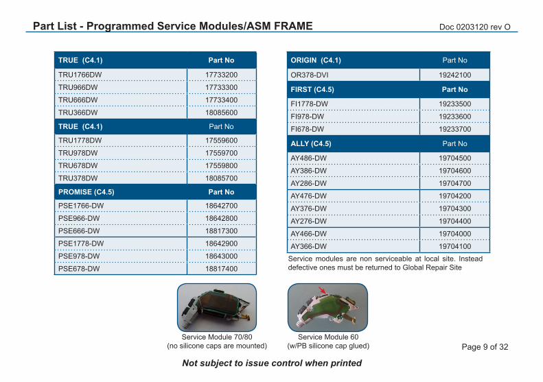
TRUE (C4.1) Part No
TRU1766DW 17733200
TRU966DW 17733300
TRU666DW 17733400
TRU366DW 18085600
TRUE (C4.1) Part No
TRU1778DW 17559600
TRU978DW 17559700
TRU678DW 17559800
TRU378DW 18085700
PROMISE (C4.5) Part No
PSE1766-DW 18642700
PSE966-DW 18642800
PSE666-DW 18817300
PSE1778-DW 18642900
PSE978-DW 18643000
PSE678-DW 18817400
Service Module 70/80(no silicone caps are mounted)
Service Module 60(w/PB silicone cap glued)
Part List - Programmed Service Modules/ASM FRAME
ORIGIN (C4.1) Part No
OR378-DVI 19242100
FIRST (C4.5) Part No
FI1778-DW 19233500
FI978-DW 19233600
FI678-DW 19233700
ALLY (C4.5) Part No
AY486-DW 19704500
AY386-DW 19704600
AY286-DW 19704700
AY476-DW 19704200
AY376-DW 19704300
AY276-DW 19704400
AY466-DW 19704000
AY366-DW 19704100
Service modules are non serviceable at local site. Instead defective ones must be returned to Global Repair Site

Doc 0203120 rev O
Page 10 of 32
Not subject to issue control when printed
Description Part No
CROS,SUREFIT,AUDIO SHOE,SMALL * 20040900
CROS,SUREFIT,AUDIO SHOE,MEDIM * 20041000
CROS,SUREFIT,AUDIO SHOE,LARGE * 20041100
CROS,SUREFIT,EUROPLUG,SMALL * 20040500
CROS,SUREFIT,EUROPLUG,MEDIUM * 20040600
CROS,SUREFIT,EUROPLUG,LARGE * 20040700
CROS,SFEURO PLUG
CROS,SFAUD SHOE
(shoe is fixed to the cable)
* Lengths: S = 25 cm, M = 28 cm, L = 31 cm (excl CROS hook)
Please also see: Doc 400604000 UG,CROS/BICROS,SUREFIT (User Guide) & 400650000 DS,CROS/BICROS,SUREFIT,GB (Data Sheet)
Part List - CROS Parts

Doc 0203120 rev O
Page 11 of 32
Not subject to issue control when printed
Description Part No
AIRLINK,COMPL (for wireless connection test)* 17292000
AIRLINK 2, GENERIC (for wireless connection test)* 17292002
PROG. CABLE EXTENSION, MILANO (HI test) 17517800
SERVICE JIG/FIXTURE 16695100
TEST FRAME (HI test) 16902800
BATTERY PILL, 13+ (70/80 models) 17449400
BATTERY PILL, 312+ (60 models) 17449300
COUPL MIC,TSYS,TM-12,MEASURED 18220700
PROG CABLE R 9022 907 69019
PROG CABLE L 9022 907 69029
PROGRAMMING ADAPTOR (generic) - incl clips red/blue 18041400
CLIP,PROGRAMMING ADAPTOR,RED 17736900
CLIP,PROGRAMMING ADAPTOR,BLUE 17736901
Please find pictures of test equipment in the last pages
Part List - Test Equipment
* both airlinks can be used

Doc 0203120 rev O
Page 12 of 32
Not subject to issue control when printed
Part List - Housing Parts - ALLY (70 / 80)
COLOUR VC TGLCOVER * PB VC TOGGLE HSG TOP HSG BOT BATT
DOOR
BGE 18093400 18093000 18093300 18093500 18093600 19937700
GRY 18093402 18093002 18093302 18093502 18093602 19937702
BRN 18093404 18093004 18093304 18093504 18093604 19937704
BLK 18093408 18645808 18093308 18646008 18644908 19937708
STG 18093420 18093020 18093320 18093520 18093620 19937720
* Can be used instead of VC toggle
All HSG parts are nano coated

Doc 0203120 rev O
Page 13 of 32
Not subject to issue control when printed
Part List - Housing Parts - ALLY (60)
COLOUR PB HSG TOP HSG BOT BATT DOOR
BGE 18093000 18092800 18093100 19937600
GRY 18093002 18092802 18093102 19937602
BRN 18093004 18092804 18093104 19937604
BLK 18645808 18645408 18644808 19937608
STG 18093020 18092820 18093120 19937620
All HSG parts are nano coated
Doc 0203120 rev O
Page 14 of 32
Not subject to issue control when printed
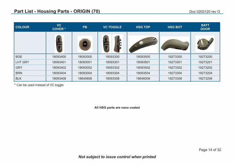
Part List - Housing Parts - ORIGIN (70)
COLOUR VC COVER * PB VC TOGGLE HSG TOP HSG BOT BATT
DOOR
BGE 18093400 18093000 18093300 18093500 19273300 19273200
LHT GRY 18093401 18093001 18093301 18093501 19273301 19273201
GRY 18093402 18093002 18093302 18093502 19273302 19273202
BRN 18093404 18093004 18093304 18093504 19273304 19273204
BLK 18093408 18645808 18093308 18646008 19273308 19273208
* Can be used instead of VC toggle
All HSG parts are nano coated
Doc 0203120 rev O
Page 15 of 32
Not subject to issue control when printed
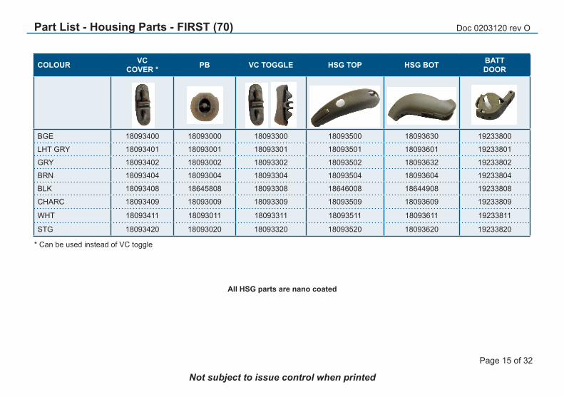
Part List - Housing Parts - FIRST (70)
COLOUR VC COVER * PB VC TOGGLE HSG TOP HSG BOT BATT
DOOR
BGE 18093400 18093000 18093300 18093500 18093630 19233800
LHT GRY 18093401 18093001 18093301 18093501 18093601 19233801
GRY 18093402 18093002 18093302 18093502 18093632 19233802
BRN 18093404 18093004 18093304 18093504 18093604 19233804
BLK 18093408 18645808 18093308 18646008 18644908 19233808
CHARC 18093409 18093009 18093309 18093509 18093609 19233809
WHT 18093411 18093011 18093311 18093511 18093611 19233811
STG 18093420 18093020 18093320 18093520 18093620 19233820
* Can be used instead of VC toggle
All HSG parts are nano coated

Doc 0203120 rev O
Page 16 of 32
Not subject to issue control when printed
Part List - Housing Parts PROMISE 70
COLOUR VC COVER * PB VC TOGGLE HSG TOP HSG BOT BATT
DOOR
BGE 18093400 18093000 18093300 18093500 18093600 18645000
LHT GRY 18093401 18093001 18093301 18093501 18093601 18645001
GRY 18093402 18093002 18093302 18093502 18093602 18645002
BRN 18093404 18093004 18093304 18093504 18093604 18645004
BLK 18093408 18645808 18093308 18646008 18644908 18645008
CHARC 18093409 18093009 18093309 18093509 18093609 18645009
WHT 18093411 18093011 18093311 18093511 18093611 18645011
STG 18093420 18093020 18093320 18093520 18093620 18645020
* Can be used instead of VC toggle
All HSG parts are nano coated

Doc 0203120 rev O
Page 17 of 32
Not subject to issue control when printed
Part List - Housing Parts PROMISE 60
COLOUR PB HSG TOP HSG BOT BATT DOOR
BGE 18093000 18092800 18093100 18093200
LHT GRY 18093001 18092801 18093101 18093201
GRY 18093002 18092802 18093102 18093202
BRN 18093004 18092804 18093104 18093204
BLK 18645808 18645408 18644808 18093208
CHARC 18093009 18092809 18093109 18093209
WHT 18093011 18092811 18093111 18093211
STG 18093020 18092820 18093120 18093220
All HSG parts are nano coated

Doc 0203120 rev O
Page 18 of 32
Not subject to issue control when printed
Part List - Housing Parts TRUE 70
COLOUR VC COVER * PB VC TOGGLE HSG TOP HSG BOT BATT
DOOR
BGE 18093400 18093000 18093300 18093500 18093600 18093700
LHT GRY 18093401 18093001 18093301 18093501 18093601 18093701
GRY 18093402 18093002 18093302 18093502 18093602 18093702
BRN 18093404 18093004 18093304 18093504 18093604 18093704
ARCTIC ICE 18093406 18093006 18093306 18093506 18093606 18093706
BLK 18093408 18645808 18093308 18646008 18644908 18093708
CHARC 18093409 18093009 18093309 18093509 18093609 18093709
STG 18093420 18093020 18093320 18093520 18093620 18093720
* Can be used instead of VC toggle
All HSG parts are nano coated

Doc 0203120 rev O
Page 19 of 32
Not subject to issue control when printed
Part List - Housing Parts TRUE 60
COLOUR PB HSG TOP HSG BOT BATT DOOR
BGE 18093000 18092800 18093100 18093200
LHT GRY 18093001 18092801 18093101 18093201
GRY 18093002 18092802 18093102 18093202
BRN 18093004 18092804 18093104 18093204
ARCTIC ICE 18093006 18092806 18093106 18093206
BLK 18645808 18645408 18644808 18093208
CHARC 18093009 18092809 18093109 18093209
STG 18093020 18092820 18093120 18093220
All HSG parts are nano coated
Colour Line
LHT GRY BGEGRYBRN
ARC ICEBLK
CHARCSTG

Doc 0203120 rev O
Page 20 of 32
Not subject to issue control when printed
THIN TUBE SF BLISTER PCK (3 cleaning wires / 5 thin tubes) RIGHT LEFT
THIN TUBE,SF,0A 19402600 19403500
THIN TUBE,SF,0B 19402700 19403600
THIN TUBE,SF,1A 19402800 19403700
THIN TUBE,SF,1B 19402900 19403800
THIN TUBE,SF,-1B 19403000 19403900
THIN TUBE,SF,2A 19403100 19404000
THIN TUBE,SF,2B 19403200 19404100
THIN TUBE,SF,3A 19403300 19404200
THIN TUBE,SF,3B 19403400 19404300
DOMES for THIN TUBE SUREFIT
Description Bag (10 pcs)
DOME,SF,OPEN,SM 19398200
DOME,SF,OPEN,MDM 19398300
DOME,SF,OPEN,LGE 19398400
DOME,SF,TULIP,STD 19398500
DOME,SF,PWR,SM 19398600
DOME,SF,PWR,MDM 19398700
DOME,SF,PWR,LGE 19398800
Description Part No
FITTING KIT,THIN TUBE,SUREFIT* 19442600
FITTING KIT,THIN TUBE,SF(EMPTY)** 19442300
CLEANER, TUBE, HE4 15168700
MEASUREMENT TOOL,MINI BTE 15200800
* contains cleaner tubes, measurement tool, all sizes thin tubes & domes** empty box with inlay - to be filled up according to needs
Please note that thin tube/dome option is for 60 / 70 models only
Thin tube2 & belonging domes are listed on next pageSureFit (SF) thin tube & belonging domes listed on the this page are the newest parts
Both Thin tube2 and SureFit will fit the 60 / 70 models
Part List - SureFit (SF)Thin Tubes & Domes (60 / 70 only)

Doc 0203120 rev O
Page 21 of 32
Not subject to issue control when printed
THIN TUBE BLISTER PACKS(5 tubes & 3 cleaning wires) Part No
THIN TUBE 2,0A,R,BLSTR 18628600
THIN TUBE 2,0B,R,BLSTR 18628700
THIN TUBE 2,1A,R,BLSTR 18628800
THIN TUBE 2,1B,R,BLSTR 18628900
THIN TUBE 2,2A,R,BLSTR 18629000
THIN TUBE 2,2B,R,BLSTR 18629100
THIN TUBE 2,3A,R,BLSTR 18629200
THIN TUBE 2,3B,R,BLSTR 18629300
THIN TUBE 2,-1B,R,BLSTR 18629400
THIN TUBE 2,0A,L,BLSTR 18629500
THIN TUBE 2,0B,L,BLSTR 18629600
THIN TUBE 2,1A,L,BLSTR 18629700
THIN TUBE 2,1B,L,BLSTR 18629800
THIN TUBE 2,2A,L,BLSTR 18629900
THIN TUBE 2,2B,L,BLSTR 18630000
THIN TUBE 2,3A,L,BLSTR 18630100
THIN TUBE 2,3B,L,BLSTR 18630200
THIN TUBE 2,-1B,L,BLSTR 18630300
THIN TUBE DOMES
Description Bag (10 pcs)
DOME,THNTUB,SZ5,SM 18500800
DOME,THNTUB,SZ7,MDM 18500900
DOME,THNTUB,SZ10,LGE 18501000
DOME,THNTB,TULIP,STD 18501100
DOME,THNTUB,PWR,SM 18265100
DOME,THNTUB,PWR,MDM 18265200
DOME,THNTUB,PWR,LGE 18265300
Part List - Thin Tubes & Domes (60 / 70 only)
Please note that thin tube/dome option is for 60 / 70 models only
Thin tube2 & belonging domes are listed on this pageSureFit (SF) thin tube & belonging domes listed on the previous page are the newest parts
Both Thin tube2 and SureFit will fit the 60 / 70 models
Doc 0203120 rev O
Page 22 of 32
Not subject to issue control when printed
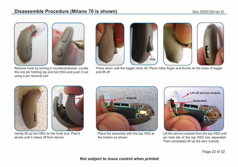
Disassemble Procedure (Milano 70 is shown)
Remove hook by turning it counterclockwise. Locate the one pin holding top and bot HSG and push it out using a pin removal tool
Gently lift up bot HSG on the hook end. Peel it slowly until it clears off from device
Place the assembly with the top HSG at the bottom as shown
Press down until the toggle clicks off. Place index finger and thumb on the sides of toggle and lift off
Gap
Lift the service module from the top HSG until pin hole tab of the top HSG has separated. Then completely lift up the serv module
AlignedSeparated
Lift off service module

Doc 0203120 rev O
Page 23 of 32
Not subject to issue control when printed
Disassemble Procedure (Milano 70 is shown)
Service module with the fixed batt door Locate the pin to separate the batt door from service module and remove it using a pin removal tool
Pin
MILANO 60 MILANO 70 / 80

Doc 0203120 rev O
Page 24 of 32
Not subject to issue control when printed
Replace Parts - (Milano 70 is shown)
When changing the bot HSG the ID plate must be transfered to new HSG. Please note that the ID plate is not an available spare part. Push out the plate from inside the old HSG by using a tweezer. Place the side of the ID plate with one prong and insert it. Use a finger to press down to make sure both sides are correct in place
ID Plate
Two prong
One prong
Push out
Replacing the toggle: Press down until toggle clicks off. Place index finger and thumb on the sides of toggle and lift off. Ensure that the silicone cap is correct in place. Mount the new toggle (or VC cover) in correct position with the small arrow pointing towards PB. Press down the toggle until it clicks in place
Gap

Doc 0203120 rev O
Page 25 of 32
Not subject to issue control when printed
Replace Parts (Milano 70 is shown)
Place the PB in top HSG and make sure it has correct direc-tion. To make it easier to reassemble top HSG, keep the posion of the HSG part as shown
Mount the PB silicone cap (on 70/80 models only, the cap on 60 models is glued)
Keep the top HSG inverted with the curve pointing downwards to keep the PB cap from falling off. Slowly place the bottom part of the service module(by the batt door) on top HSG making sure that the pin hole tab of top HSG is aligned with the module
PB
Aligned
Add batt door to the service module and push in the pin
Bot area of module
Pin hole tab
Place the bot HSG by the batt door area first and moving towards the rec hole area. Push in the pin and mount the hook by turning it clockwise

Doc 0203120 rev O
Page 26 of 32
Not subject to issue control when printed
Hook, Hook Filter & Thin Tubes/Domes
Remove the hook from HI by turning counterclockwise. Release the filter removal tool from filter frame. Insert the filter tool into the pipe and push out the filter. Mount the hook to the HI by turning clockwise. Mount the new filter as shown
Note: If the model is a Power or a Power configured to High Gain, the filter must NOT be inserted. Furthermore for the High Power configuration, the metal hook must be chosen (without filter)
Mount the thin tube adapt to the HI by turning clockwise. Remove the “stop”. Choose a thin tube and dome in suitable sizes and mount as shown (see part list for available sizes tubes and domes) Note: Thin tube option available for Milano 60/70 models only

Doc 0203120 rev O
Page 27 of 32
Not subject to issue control when printed
Service Procedure:
- Save user settings with Solus - Disassemble faulty device- Replace module with a new service module from stock- Assemble device- Restore user settings with Solus- Load customer serial no (ID Plate) using DSA6000
Postponement Procedure:
- Disassemble device- Replace parts with new parts from stock- Transfer ID-plate from old housing to new housing- Verify battery door by open and close once
Service & Postponement Procedure

Doc 0203120 rev O
Page 28 of 32
Not subject to issue control when printed
Test Equipment
Batt pill must be used during test
17449300 size 31217449400 size 13
Instrument fixturep/n 16695100for final HI test
Test frame p/n 16902800
Prog adapt(generic)18041400
CS44 Prog cable(Left blue is shown)9022 907 69019 (R)9022 907 69029 (L)
P/n 17517800Prog cable ext must be
used during final HI test due to current measurement (not used with fitting SW)
Prog adapt clip17736900 Red17736901 Blue
2cc couplerp/n 30-4838800
Both parts can be ordered with GTO
Dept/HQ DK
2cc coupl insert BTEp/n 40B4609601
To be used with prog adapt 18041400
18220700COUPL MIC,TM12
MEASURED
17292000 Airlinkor 17292002 Airlink 2
to be used for wireless “Conn test”
Doc 0203120 rev O
Page 29 of 32
Not subject to issue control when printed
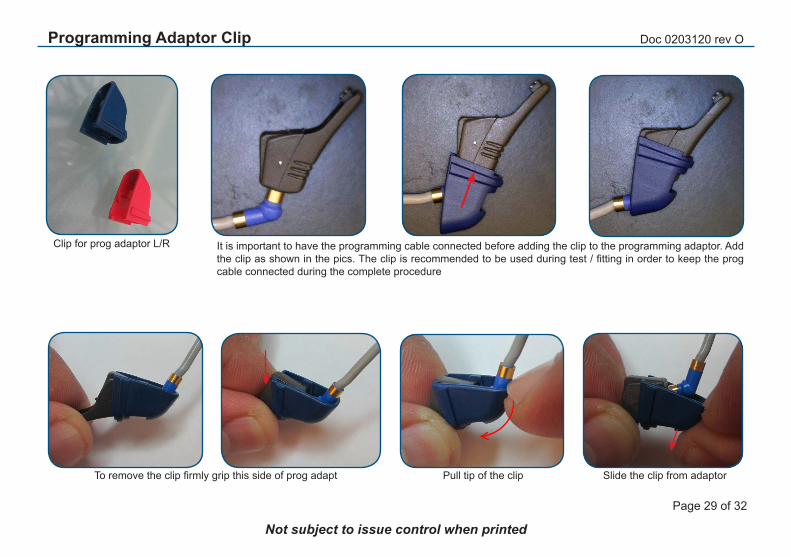
To remove the clip firmly grip this side of prog adapt Pull tip of the clip Slide the clip from adaptor
It is important to have the programming cable connected before adding the clip to the programming adaptor. Add the clip as shown in the pics. The clip is recommended to be used during test / fitting in order to keep the prog cable connected during the complete procedure
Clip for prog adaptor L/R
Programming Adaptor Clip

Doc 0203120 rev O
Page 30 of 32
Not subject to issue control when printed
Add a batt pill and close batt door. Insert the one end of the prog adapt into the square prog port of the device
Push the bottom part of prog adapt until it clicks to lock it on the device
Connect the CS44 prog cable
Button(press down to unlock after use)
Connect the prog cable to the extension prog cable and connect the extension prog cable to the DSA6000
Testing

Doc 0203120 rev O
Page 31 of 32
Not subject to issue control when printed
Use of test fixture is mandatory for all Milano BTE during DSA6000 final HI testing. To use the fixture, place the HI in the fixture according to pic. Place it in the test chamber as shown and select the correct test tpix and make sure to follow instructions coming up on the screen. During the test programme execution the IAD calibration will be performed at the appropriate time. Another bennefit from the fixture is that the HI is in a well defined position so the telecoil test can be performed without any interaction from the operator.
If a tinnitus breaker version (TBR) is prefered, the TBR option should be chosen
Test tubing is normal 20 mm effective lenght as for all AUDIOmaster BTE testing
Place the HI in test chamber as shown
20 mm
Testing
2cc couplerp/n 30-4838800
2cc coupler insert BTEp/n 40B4609601
Both coupler parts can be ordered with GTO Dept/HQ Ballerup DK

Doc 0203120 rev O
Page 32 of 32
Not subject to issue control when printed
Wireless Test - Connection Test
Wireless test using Airlink / Airlink 2:The “RF (Radio Frequency) signal test” is performed during hybrid test. In service & repair situations only a connection test is needed. The DSA6000 can perform a connection test to test the wireless function on the devices. The test is performed using an Airlink or Airlink 2 mounted directly in any of the DSA 6000 units USB ports. No fixture is required performing a Connection test
The test is performed in the open air on the desktop. During a DSA6000 test prog running the connection test the operator will be asked to place the device in the WL Test point. During the connection test the device does not need to be connected with a prog cable and a batt pill. Instead a fresh batt must be inserted. The connec-tion test is a part of the Final Device Test running on the DSA 6000. The test system will search for a device with a s/n matching the s/n for the Device Under Test (DUT) in the running test sequence
To make sure the device is in boot mode the batt must be inserted immediately before the [Start] button is pressed. The WL Test point is a spot on the table approx 20 cm away from the Airlink dongle. The s/n matching will pre-vent connection with any other wireless devices in the nearby area. Best practice is to first insert the battery and immediately after press the Start button (within 5 sec). Inserting the batt will start the device boot se-quence
Note:An extended wireless test using a TV streamer / SAS is introduced. Please find more detailed info in Tech Bulletin No. 2013-05-002 “Improved functionality for the RF Range check on DSA 6000” on GTO web site where also other info about wireless test can be found