technical manual - enviro...3 introduction * this manual is designed for the technician in...
TRANSCRIPT

MERIDIAN-1P E L L E T S T O V E
WARRANTY REGISTRATION
enviro.com/warranty
50-1485
PLEASE READ THIS ENTIRE MANUAL BEFORE INSTALLATION AND USE OF THIS PELLET BURNING ROOM HEATER. FAILURE TO FOLLOW THESE INSTRUCTIONS COULD RESULT IN PROPERTY DAMAGE, BODILY INJURY OR EVEN DEATH
CONTACT YOUR BUILDING OR FIRE OFFICIALS ABOUT RESTRICTIONS AND INSTALLATION INSPECTION REQUIREMENTS IN YOUR AREA.
INSTALLER: LEAVE THIS MANUAL WITH THE STOVE.CONSUMER: RETAIN THIS MANUAL FOR FUTURE REFERENCE.
Version française: www.enviro.com/fr
TECHNICAL MANUAL

Table of Contents
Introduction...................................................................................................................................3Rating Label Location...........................................................................................................3Important Safety Data..........................................................................................................3Safety Warnings And Recommendations................................................................................3
Installation.....................................................................................................................................5Deciding Where to Locate your Pellet Appliance.....................................................................5Removing Pellet Stove From Pallet.........................................................................................5Dimensions - Freestanding....................................................................................................6Dimensions - Fireplace Insert................................................................................................6Clearances to Combustibles - Freestanding............................................................................7Alcove Clearances - Freestanding..........................................................................................7Clearances to Combustibles - Fireplace Insert.........................................................................8Installation of Pedestal and Leveling Legs - Fireplace Insert....................................................8Installing Hopper Cover and Adjusting Hopper Height - Fireplace Insert...................................8Mobile Home Installation - Freestanding:...............................................................................9Vent Termination Requirements...........................................................................................10Exhaust And Fresh Air Intake Locations...............................................................................11Outside Fresh-Air Connection..............................................................................................11Corner Through Wall Installation - Freestanding...................................................................12Horizontal Exhaust Through Wall Installation - Freestanding..................................................12Vertical Rise with Horizontal Termination Installation (Recommended) - Freestanding..............14Through Concrete Wall With Vertical Rise Installations - Freestanding....................................14Inside Vertical Installations - Freestanding...........................................................................15Outside Vertical Installations - Freestanding.........................................................................16Hearth Mount Installation - Freestanding.............................................................................17Installation with Exterior Mounted Exhaust Blower - Freestanding..........................................18Through Wall Vertical Installation With Exhaust Blower - Freestanding...................................20Masonry Fireplace Insert Installation - Fireplace Insert..........................................................21Positive Flue Connection without a Full Reline - Fireplace Insert (USA Only)............................22Installation and Removal of Control Panel in The Surround Panel - Fireplace Insert.................23Assembly and Installation of Insert Surround Panels - Fireplace Insert...................................23Plated Trim Installation.......................................................................................................24Plated Door Installation......................................................................................................25Thermostat Installation.......................................................................................................26Slider/Damper Set-Up.........................................................................................................26
Troubleshooting............................................................................................................................28
Wiring Diagram.............................................................................................................................31
Parts List - Components.................................................................................................................32
Parts List - Options........................................................................................................................34
Parts Diagram - Components..........................................................................................................35
Parts Diagram - Freestanding Steel.................................................................................................36
Parts Diagram - Insert Steel...........................................................................................................37
Notes......................................................................................................................................38
Warranty......................................................................................................................................39
Installation Data Sheet..................................................................................................................402

3
Introduction* This manual is designed for the technician in conjunction with the owner’s manual. *
Rating LabeL Location:
The rating label is located on the inside of the ash pan cover.
impoRtant Safety Data:
Please read this entire Owner’s Manual before installing or operating your ENVIRO Pellet Stove. Failure to follow these instructions may result in property damage, bodily injury or even death. Contact your local building or fire official to obtain a permit and any information on installation restrictions and inspection requirements for your area.
To prevent the possibility of a fire, ensure that the appliance is properly installed by adhering to the installation instructions. An ENVIRO dealer will be happy to assist you in obtaining information with regards to your local building codes and installation restrictions.
Be sure to maintain the structural integrity of the home when passing a vent through walls, ceilings, or roofs.
The stove’s exhaust system works with negative combustion chamber pressure and a slightly positive chimney pressure. It is very important to ensure that the exhaust system be sealed and airtight. The ash pan and viewing door must be locked securely for proper and safe operation of the pellet stove.
Do not burn with insufficient combustion air. A periodic check is recommended to ensure proper combustion air is admitted to the combustion chamber. Setting the proper combustion air is achieved by adjusting the slider damper located on the left side of the stove.
When installing the stove in a mobile home, it must be electrically grounded to the steel chassis of the home and bolted to the floor. Make sure that the structural integrity of the home is maintained and all construction meets local building codes.
Minor soot or creosote may accumulate when the stove is operated under incorrect conditions such as an extremely rich burn (black tipped, lazy orange flames).
If you have any questions with regard to your stove or the above-mentioned information, please feel free to contact your local dealer for further clarification and comments.
Safety WaRningS anD RecommenDationS:
Caution: Do not connect to any air distribution duct or system.Do not burn garbage or flammable fluids such as gasoline, naptha or engine oil.Unit hot while in operation. Keep children, clothing and furniture away. Contact may cause skin burns.
SOOT: Operation of the stove with insufficient combustion air will result in the formation of soot which will collect on the glass, the heat exchanger, the exhaust vent system, and may stain the outside of the house. This is a dangerous situation and is inefficient. Frequently check your stove and adjust the slider/damper as needed to ensure proper combustion. See: “SLiDeR/DampeR Setting”.
CLEANING: There will be some build up of fly ash and small amounts of creosote in the exhaust. This will vary due to the ash content of the fuel used and the operation of the stove. It is advisable to inspect and clean the exhaust vent semi-annually or every two tons of pellets.

4
Introduction
ELECTRICAL: The use of a surge protected power bar is recommended. The unit must be grounded. The grounded electrical cord should be connected to a standard 115 volts (4.6 Amps), 60 hertz electrical outlet. Be careful that the electrical cord is not trapped under the appliance and that it is clear of any hot surfaces or sharp edges and also must be accessible. If this power cord should become damaged, a replacement power cord must be purchased from the manufacture or a qualified ENVIRO dealer. This unit’s maximum power requirement is 520 watts.
GLASS: Do not abuse the glass by striking or slamming the door. Do not attempt to operate the stove with broken glass. The stove uses ceramic glass. Replacement glass must be purchased from an ENVIRO dealer. Do not attempt to open the door and clean the glass while the unit is in operation or if glass is hot. To clean the glass, use a soft cotton cloth and mild window cleaner, gas or wood stove glass cleaner, or take a damp paper towel and dip into the fly ash. This is a very mild abrasive and will not damage the glass.
FLAMMABLE LIQUIDS: Never use gasoline, gasoline-type lantern fuel, kerosene, charcoal lighter fluid, or similar liquids to start or “freshen up” a fire in the heater. Keep all such liquids well away from the heater while it is in use.
SMOKE DETECTOR: Smoke detectors should be installed and maintained in the structure when installing and operating a pellet burning appliance.
OPERATION: The ash pan and door must be closed securely for proper and safe operation of the pellet stove. Also ensure all gaskets on the door are checked and replaced when necessary.
INSTALLATION: Be sure to maintain the structural integrity of your home when passing a vent through walls, ceilings, or roofs. It is recommended that the unit be secured into its position in order to avoid any displacement.
DO NOT INSTALL A FLUE DAMPER IN THE EXHAUST VENTING SYSTEM OF THIS UNIT.
DO NOT CONNECT THIS UNIT TO A CHIMNEY FLUE SERVING ANOTHER APPLIANCE.
FRESH AIR: Outside Fresh Air connection is optional. Must be connected to all units installed in Mobile and “Air Tight Homes” (R2000) or where required by local codes. Consider all large air moving devices when installing your unit and provide room air accordingly. Limited air for combustion may result in poor performance, smoking and other side effects of poor combustion.
If you have any questions with regards to your stove or the above-mentioned information, please feel free to contact your local dealer for further clarification and comments.
SINCE SHERWOOD INDUSTRIES LTD. HAS NO CONTROL OVER THE INSTALLATION OF YOUR STOVE, SHERWOOD INDUSTRIES LTD. GRANTS NO WARRANTY IMPLIED OR STATED FOR THE INSTALLATION OR MAINTENANCE OF YOUR STOVE. THEREFORE, SHERWOOD INDUSTRIES LTD. ASSUMES NO RESPONSIBILITY FOR ANY CONSEQUENTIAL DAMAGE(S).
SAVE THIS INSTRUCTION MANUAL FOR FUTURE REFERENCE

Installation
DeciDing WheRe to Locate youR peLLet appLiance:
1. Check clearances to combustibles (see InstallatIon - ClearanCes to CombustIbles - FreestandIng, InstallatIon - alCove ClearanCes - FreestandIng, and InstallatIon - ClearanCes to CombustIbles - FIreplaCe Insert.
2. Do not obtain combustion air from an attic, garage or any unventilated space. Combustion air may be obtained from a ventilated crawlspace.
3. Do not install the stove in a bedroom.
4. You can vent the stove through an exterior wall behind the unit or connect it to an existing masonry or metal chimney (must be lined if the chimney is over 6” (15 cm) diameter, or over 28 inches² (180 cm²) cross sectional area). An interior vent can be used with approved pipe passing through the ceiling and roof.
5. Locate the stove in a large and open room that is centrally located in the house. This will optimize heat circulation.
6. The power cord is 8 feet (2.43 m) long and may require a grounded extension cord to reach the nearest electrical outlet.
Removing peLLet Stove fRom paLLet:
To remove your new stove from its pallet, remove the two (2) screws securing the bottom to the pallet.
Freestanding: One screw can be easily seen from behind but to access the second screw the ashpan must be removed.
Fireplace Insert: There is one screw on either side of the bottom.
Figure 1: Removing Freestanding Stove From the Pallet. Figure 2: Removing Insert Stove From the Pallet.
5

32 1/2"(826mm)
24 7/8"(632mm)
24 3/4"(629mm)
Installation
DimenSionS - fReeStanDing:
Figure 3: Meridian Freestanding Dimensions.
23 3/4"(604mm)
12 7/8"(326mm)
22 7/8"(583mm)
23 7/8"(605mm)
Figure 4: Meridian Fireplace Insert Dimensions.
DimenSionS - fiRepLace inSeRt:
6

Minimum6" (150mm)
This pellet stove requires floor protection. The floor protection must be non-combustible, extending beneath the stove the full width and depth of the unit including 6“ (150 mm) in front for ember protection.
aLcove cLeaRanceS - fReeStanDing:
Figure 5: Meridian on Floor Protection.
Minimum Width 36" (914mm)
Minimum Height 48" (1219mm)
Maximum Depth 30" (762mm)
Back wall
Sid
e w
all
Adjacentwall
2"(51mm)
3" (76mm)
6"(152mm)
Installation
cLeaRanceS to combuStibLeS - fReeStanDing:
These dimensions are minimum clearances but it is recommended that you ensure sufficient room for serving, routine cleaning and maintenance.
Figure 6: Minimum Clearances to Combustibles for Freestanding Meridian.
Figure 7: Alcove Clearances Freestanding Meridian.
7

Installation
cLeaRanceS to combuStibLeS - fiRepLace inSeRt:
The fireplace insert must be installed into a masonry fireplace. This model includes a surround faceplate and a pedestal. When installing this unit, ensure that the pedestal is removed from the inside of the hopper and installed on the bottom of the unit. Refer to InstallatIon - InstallatIon oF pedestal and levelIng legs - FIreplaCe Insert and InstallatIon - InstallIng Hopper Cover and adjustIng Hopper HeIgHt - FIreplaCe Insert before proceeding.From the body of the heater to the side wall: 8 inches (203 mm) minimumFrom the body of the heater to the Facing on masonry fireplace: 8 inches (203 mm) minimumFrom the body of the heater to the 8” (203 mm) mantle: 8 inches (203 mm) minimum
inStaLLation of peDeStaL anD LeveLing LegS - fiRepLace inSeRt:
There are two parts to the Meridian insert pedestal and they can be found inside the hopper. Place unit on its back. Two (2) hex head screws are used on each side of the pedestal (refer to Figure 8). Using a 5/16” wrench or socket attach the pedestal to the bottom of the unit.
Leveling Legs
inStaLLing hoppeR coveR anD aDjuSting hoppeR height - fiRepLace inSeRt:
The hopper cover initially comes upside-down on top of the hopper. To install the hopper cover flip the cover over and fasten in place with four T-20 screws (see Figure 10).
The back height of this unit can be set to one (1) of three (3) heights; 19” (483 mm), 21⅛” (537 mm), 22¼” (565 mm). The hopper should be set to the maximum height that can be used in the installation.
To change the height of the hopper back up or down, remove the seven (7) T-20 screws, three (3) on each side and one (1) on the back. The screw placement is shown Figure 11. Move the hopper assembly to the required setting and replace the screws. When the hopper back is in place it is recommended that silicone is used to seal the bottom lip of the hopper back and sides
OPTIONAL:
There are two (2) leveling legs and they can be found inside the manual bag. Each leveling leg consists of a long bolt, a hex nut, a washer, and a square bolt with clip (see Figure 9). For installation of the leveling legs the unit should be on its back and a ½” wrench is required for adjustments.
Install the square bolts into the square holes in the back corners of the bottom. The square bolt should be inserted from inside the unit so that the clip will be facing up.
Thread hex nut onto the bolt till it is approximately 1” (25 mm) from the bolt head, slide washer onto bolt. Thread the bolt into the square nut so length of the bolt shown is the approximately height needed for leveling. When the unit is up right and the bolts can be adjusted to the exact height required. To lock the bolts at a height tighten the hex nut and washer against the square bolt
Figure 8: Installing Pedestal. Figure 9: Square Bolt.
8

Ground wire directlyconnected to metal chassis.
Hearth Pad
Flooring
Steel Frame
1/4" Lag boltssecurely fastened
Figure 12: Mobile Home Install Mounting.
mobiLe home inStaLLation - fReeStanDing:
● Secure the heater to the floor using the holes in the pedestal of the appliance.
● Ensure the unit is electrically grounded to the chassis of your home (permanently).
WARNING: Do not install in a room people sleep in.
CAUTION: The structural integrity of the manufactured home floor, wall and ceiling/roof must be maintained
• Outside fresh air is mandatory. Secure outside air connections directly to fresh air intake pipe and secure with three (3) screws evenly spaced.
Installation
Figure 10: Hopper Cover Screw Placement. Figure 11: Hopper Extension Screw Placement.
9

10
hot enough to cause burns if touched by children. Non-combustible shielding or guards may be required.
3. Termination must exhaust above the inlet elevation. It is recommended that at least five feet of vertical pipe be installed outside when the appliance is vented directly through a wall, to create some natural draft to prevent the possibility of smoke or odor during appliance shut down or power failure. This will keep exhaust from causing a nuisance or hazard from exposing people or shrubs to high temperatures. In any case, the safest and preferred venting method is to extend the vent through the roof vertically.
4. Distance from the bottom of the termination and grade is 12” (30 cm) minimum. This is conditional upon the plants and nature of grade surface. The exhaust gases are hot enough to ignite grass, plants and shrubs located in the vicinity of termination. The grade surface must not be lawn.
5. If the unit is incorrectly vented or the air to fuel mixture is out of balance, a slight discoloration of the exterior of the house might occur. Since these factors are beyond the control of Sherwood Industries Ltd, we grant no guarantee against such incidents.
NOTE: Venting terminals shall not be recessed into walls or siding.
Installation
vent teRmination RequiRementS:
IT IS RECOMMENDED THAT YOUR PELLET STOVE BE INSTALLED BY AN AUTHORIZED DEALER/INSTALLER.
Figure 13: Use in conjunction with Table 1 for allowable exterior vent termination locations.
Table 1: Use in conjunction with Figure 13 for allowable exterior vent termination locations.
Air Supply Inlet Gas Meter Restriction Zone(Termination not allowed)
Termination CapG
GOpens
Opens
Opens
D F
B
B
A I
H
KG
G
L
C
E
1. Do not terminate the vent in any enclosed or semi-enclosed areas such as a carport, garage, attic, crawlspace, narrow walkway, closely fenced area, under a sundeck or porch, or any location that can build up a concentration of fumes such as stairwells, covered breezeway, etc.
2. Vent surfaces can become
Letter Minimum Clearance Description
A 24 in (61 cm) Above grass, top of plants, wood, or any other combustible materials.
B 48 in (122 cm) Beside/below any door or window that may be opened. (18” (46 cm) if outside fresh air installed.)
C 12 in (30 cm) Above any door or window that may be opened. (9” (23 cm) if outside fresh air installed.)
D 24 in (61 cm) To any adjacent building, fences and protruding parts of the structure.
E 24 in (61 cm) Below any eave or roof overhang
F 12 in (30 cm) To outside corner.
G 12 in (30 cm) To inside corner, combustible wall (vertical and horizontal terminations).
H 3 ft (91 cm) within a height of 15 ft (4.5 m) above the meter/regulator assembly
To each side of center line extended above natural gas or propane meter/regulator assembly or mechanical vent.
I 3 ft (91 cm) From any forced air intake of other appliance
J 12 in (30 cm) Clearance to non-mechanical air supply inlet to building, or the combustion air inlet to any appliance.
K 24 in (61 cm) Clearance above roof line for vertical terminations.
L 7 ft (2.13 m) Clearance above paved sidewalk or paved driveway located on public property.

EXHAUST Freestanding InsertBase of unit to center of flue 18 ⅝” (473 mm) 9 1/16” (229 mm)Side of unit to center of flue 6 11/16” (170 mm) 6 ⅛” (156 mm)Center of unit to center of flue 5 ¾” (146 mm) 5 ¾” (146 mm)
FRESH AIR INTAKE.Base of unit to center of intake 13 1/16” (332 mm) 3 7/16” (87 mm)Side of unit to center of intake 11 7/16” (291 mm) 10 ⅞” (277 mm)Center of unit to center of flue 1” (25 mm) 1” (25 mm)
INSTALL VENT AT CLEARANCES SPECIFIED BY THE VENTING MANUFACTURER
outSiDe fReSh-aiR connection:
1"(25mm)
11 7/16"(291mm)
6 11/16"(170mm)
13 1/16"(332mm)
18 5/8"(473mm)
5 3/4"(146mm)
1"(25mm)
5 3/4"(146mm)
3 7/16"(87mm)
10 7/8"(277mm)
6 1/8"(156mm)
9 1/16"(229mm)
Outside fresh air is mandatory when installing this unit in airtight homes and mobile homes.
A Fresh-air intake is strongly recommended for all installations. Failure to install intake air may result in improper combustion as well as the unit smoking during power failures.
When connecting to an outside fresh air source, do not use plastic or combustible pipe. A 2” minimum (51 mm) ID (inside diameter) steel, aluminum or copper pipe should be used. It is recommended, when you are installing a fresh air system, to keep the number of bends in the pipe to a minimum.
Installation
exhauSt anD fReSh aiR intake LocationS:
2" ID(51 mm)
OptionalElbow
OutsideWall
Figure 16: Outside Air Connection.
Figure 14: Meridian Freestanding Inlet and Outlet Location.
Figure 15: Meridian Insert Inlet and Outlet Location.
11

Figure 17: Corner Installation.
3" (7.5 cm)
3"(7.5 cm)
Fresh Air Intake
Wall thimblemanufacturedby pellet ventmanufacturer.
Installation
coRneR thRough WaLL inStaLLation - fReeStanDing:
hoRizontaL exhauSt thRough WaLL inStaLLation - fReeStanDing:
Vent installation: install vent at clearances specified by the vent manufacturer.
A chimney connector shall not pass through an attic or roof space, closet or similar concealed spaces, or a floor, or ceiling. Where passage through a wall or partition of combustible construction is desired, the installation shall conform to CAN/CSA-B365 Installation Code for Solid-Fuel-Burning Appliances and Equipment. Only use venting of L or PL type with an inside diameter of 3 or 4 inches (7.6 or 10.1 cm).
1. Choose a location for your stove that meets the requirements stated in this manual and allows installation with the least amount of interference to house framing, plumbing, wiring, etc.
2. Install a non-combustible hearth pad (where necessary).
3. Place the appliance 15” (37.5 cm) away from the wall. If the stove is to be set on a hearth pad, set the unit on it.
4. Locate the center of the exhaust pipe on the stove. Extend that line to the wall. Once you have located the center point on the wall, refer to pellet vent manufacturer installation instructions for correct hole size and clearance to combustibles.
5. Install the wall thimble as per the instructions written on the thimble. Maintain an effective vapour barrier in accordance with local building codes.
6. Install a length of 3” (76 mm) or 4” (101 mm) vent pipe into the wall thimble. The pipe should install easily into the thimble.
7. Install the fresh air intake (see InstallatIon - outsIde FresH aIr ConneCtIon).
8. Connect the exhaust vent pipe to the exhaust pipe on the stove. Seal the connection with high temperature silicone.
9. Push the stove straight back, leaving a minimum of 2” (5 cm) clearance from the back of the stove to the wall. Seal the vent pipe to the thimble with high temperature silicone.
12
Exhaust Tube
3" (75mm) or 4" (100mm)"PL" or "L" vent
Wall Thimble
45° Elbow with screen or Termination Cap
Fresh Air Intake High Temperature RTV Silicone Required
Wall framing
Wall thimble
Termination cap
Vent pipe
Horizontal frame for thimble
ENVIRO Meridian
• This is due to the back pressure in the exhaust caused by airflow around the structure.
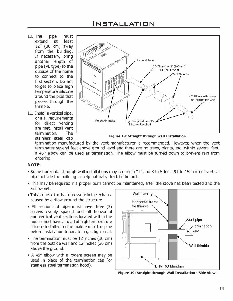
• All sections of pipe must have three (3) screws evenly spaced and all horizontal and vertical vent sections located within the house must have a bead of high temperature silicone installed on the male end of the pipe before installation to create a gas tight seal.
• The termination must be 12 inches (30 cm) from the outside wall and 12 inches (30 cm) above the ground.
• A 45° elbow with a rodent screen may be used in place of the termination cap (or stainless steel termination hood).
Installation
Figure 18: Straight through wall Installation.
10. The pipe must extend at least 12” (30 cm) away from the building. If necessary, bring another length of pipe (PL type) to the outside of the home to connect to the first section. Do not forget to place high temperature silicone around the pipe that passes through the thimble.
11. Install a vertical pipe, or if all requirements for direct venting are met, install vent termination. The stainless steel cap termination manufactured by the vent manufacturer is recommended. However, when the vent terminates several feet above ground level and there are no trees, plants, etc. within several feet, a 45° elbow can be used as termination. The elbow must be turned down to prevent rain from entering.
NOTE:
• Some horizontal through wall installations may require a “T” and 3 to 5 feet (91 to 152 cm) of vertical pipe outside the building to help naturally draft in the unit.
• This may be required if a proper burn cannot be maintained, after the stove has been tested and the airflow set.
Figure 19: Straight through Wall Installation - Side View.
13

Wall framing
Wall thimble
Termination cap
Vertical section of vent pipe
Horizontal frame for thimble
Clean out tee
90°elbow
ENVIRO Meridian
Concrete Wall
Wall framing
Wall thimble
Termination cap
Vertical section of vent pipe
Horizontal frame for thimble
Clean out tee
90°elbow
ENVIRO Meridian
Wall strap
Installation
veRticaL RiSe With hoRizontaL teRmination inStaLLation (RecommenDeD) - fReeStanDing:
A 45° elbow with a rodent screen may be used in place of the termination cap (or stainless steel termination hood).
thRough concRete WaLL With veRticaL RiSe inStaLLationS - fReeStanDing:
A 45° elbow with a rodent screen may be used in place of the termination cap (or stainless steel termination hood).
This is the recommended installation to use if there is a concrete or retaining wall in line with exhaust vent on pellet stove.
The termination must be 12 inches (30 cm) from the outside wall and 12 inches (30 cm) above the ground.
Figure 21: Vertical rise with Horizontal Termination.
Figure 20: Through Wall with Horizontal Termination.
14

Rain cap - ensure cap is at
least 2 feet (610mm) above the roof at the lowest point
Storm collar
Roof flashing
Roof rafter
Fire stop with Support Collar
Ceiling joist
Vertical vent pipe
Clean out tee with Pipe adapter
ENVIRO Meridian
NOTE:All vent sections must maintian 3" (76 mm) clearances to combustibles.
Installation
inSiDe veRticaL inStaLLationS - fReeStanDing:
1. Choose a stove location that is ideal. See the section “InstallatIon - deCIdIng WHere to loCate your pellet applIanCe.”
Figure 22: Inside Vertical Installation.
2. Place the unit on the hearth pad (if installed on a carpeted surface) and space the unit in a manner so when the pellet vent is installed vertically, it will be 3” (76 mm) away from a combustible wall.
3. Locate the center of the fresh air intake pipe on the unit. Match that center with the same point on the wall and cut a hole about 2” (51 mm) in diameter.
4. Install the fresh air intake pipe.
5. Install the tee with clean out.
6. Install the pellet vent upward from there. When you reach the ceiling, make sure that the vent goes through the ceiling fire stop. Maintain a 3” (76 mm) distance to combustibles and keep attic insulation away from the vent pipe. Maintain an effective vapor barrier.
7. Finally, extend the pellet vent to go through the roof flashing.
8. Ensure that the rain cap is approximately 24” (610 mm) above the roof.
15
Installation
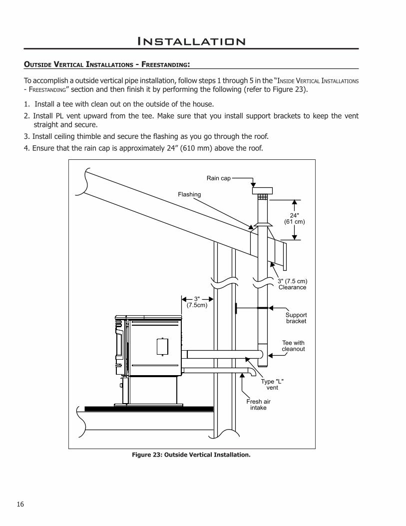
outSiDe veRticaL inStaLLationS - fReeStanDing:
To accomplish a outside vertical pipe installation, follow steps 1 through 5 in the “InsIde vertICal InstallatIons - FreestandIng” section and then finish it by performing the following (refer to Figure 23).
1. Install a tee with clean out on the outside of the house.
2. Install PL vent upward from the tee. Make sure that you install support brackets to keep the vent straight and secure.
3. Install ceiling thimble and secure the flashing as you go through the roof.
4. Ensure that the rain cap is approximately 24” (610 mm) above the roof.
Rain cap
Flashing
24"(61 cm)
3"(7.5cm)
Tee withcleanout
Fresh airintake
3" (7.5 cm)Clearance
Supportbracket
Type "L"vent
Figure 23: Outside Vertical Installation.
16

Rain cap
Storm collar
Seal plate (cover plate)
Existing masonry flue
Vent pipe (single wall stainless flex pipe or solid PL vent)
Fireplace damper location
Clean out tee
Existing fireplace
Flexible vent connector (use this 5' [1520 mm] section of pipe to vent past fireplace damper or small shelf)
1. Lock fireplace damper in the open position.
2. Install a positive flue connector at the fireplace dampers.
3. Connect a clean-out tee or a 90° elbow to the exhaust pipe.
4. Install flexible stainless steel liner or listed pellet vent to the top of the chimney.
FloorProtection
Combustible FloorMasonry Fireplace
Min 6" (150 mm)
MantelMinimum 8" (20 cm) from top of stove
Damper Removedor Fastened Open
Clean-out
Fresh-air intake should com from chimney. If holes
already exist fresh-air intake can be taken through back of the fireplace or through
the ash dump.
Installation
heaRth mount inStaLLation - fReeStanDing:
Figure 24: Hearth Mount - Side View.
Figure 25: Hearth Mount - Over View.
17

Installation
inStaLLation With exteRioR mounteD exhauSt bLoWeR - fReeStanDing:
The MERIDIAN can be equipped with an externally mounted exhaust blower (PART #20-070). This optional kit will include all components necessary to install the exhaust blower on any external vertical wall surface.
Choose a location for your stove that meets the requirements stated in this manual and allows installation with the least amount of interference to house framing, plumbing, wiring, etc.
Included in the exterior mounted exhaust blower kit are:1 - Exhaust blower housing box.1 - Blower cover plate.1 - Hardware bag
Exhaust motor must be replaced with cover
Left side with cab side removed
Exhaust motor
Complete assembly - Exterior blower & housing
1. Open the left side of the unit and the back grill and disconnect the Exhaust Blower wires from the harness. Remove the exhaust blower by undoing the six (6) ¼ hex head sheet metal screws that fasten the blower to the housing.
2. Remove the back grill from the exterior exhaust vent housing and remove the round cover plate installed on the blower housing.
3. Install the round cover plate over the gasketed opening in the stove where the exhaust motor was removed from.
4. Install the exhaust blower motor in the Exterior Vent Housing Box onto the exhaust blower housing.
5. Follow the procedures for InstallatIon - HorIzontal exHaust tHrougH Wall InstallatIon - FreestandIng. Place the unit in the desired location. Cut the hole in the wall at the desired location. Install a wall thimble.
6. Drill holes in the wall thimble in the corresponding locations for wire and fresh air if needed. Install wire clamps and feed wire through the hole in the thimble into the house. Tighten clamp on wire and attach green ground wire (at the symbol) with the screw and star washer provided.
7. Attach a short or an adjustable section of 3” of double wall pellet vent through the wall thimble to the stove. Seal all joints with silicone. Maintain clearances to combustibles.
8. Apply silicone to the pipe in the Exhaust Box, slide the pipe into the exhaust vent. Mount the Exhaust Box to the house. Reinstall the back grill on the Exterior Vent Housing Box. Apply normal venting practices when installing the vertical vent pipe.
9. Connect the wires in the stove. Re-install the Left side and Back Grill on the stove.
10. Set the Slider Damper as described in the InstallatIon - slIder/damper settIng“ section.
Figure 26: Exterior Exhaust Blower.
18

TO SUPPLY POWER TO THE EXHAUST BLOWER:
Install an amour coated electrical cable from the exhaust blower housing, through the wall thimble, and attach to the pre-drilled hole in the left hand rear hopper pillar. Hook up to wires from the wiring harness for the exhaust blower. All electrical connections must be in accordance with local code requirements (see WIrIng dIagram).
Installation
NOTE:
Ensure that all vent connections are installed by placing three (3) screws evenly spaced and a small bead of high temperature silicone at each chimney connection. Also ensure that all vertical vent sections are properly supported and that all clearances to combustibles are maintained in accordance with the vent manufacturer’s specifications.
Vent termination cap (stainless steel termination
hood) or 45° elbow with rodent screen
90° elbow
Wall strap (recommended with
use of vent pipe)
Exterior blower and housing
Vent pipe or 2 foot (610 mm) riser
Pipe adapter (if using 2 foot riser)
Wall framing
Wall thimble
Horizontal frame for thimble
ENVIRO Meridian
Armour cable supplying power to exterior blower
Siding
Figure 27: Exhaust Blower Installation; Horizontal Termination.
19

Installation
thRough WaLL veRticaL inStaLLation With exhauSt bLoWeR - fReeStanDing:
Refer to InstallatIon - InstallatIon WItH exterIor mounted exHaust bloWer - FreestandIng and InstallatIon - outsIde vertICal InstallatIons - FreestandIng. Ensure that vent pipe is properly secured to wall using wall straps. Maintain clearances to combustibles on vent pipe as well as unit.
Rain Cap
Roof sheathing
Storm collar
Roof flashing
Roof rafters
Ceiling joists
Vent Pipe
Exterior wall sheathing
Outside vent termination
Figure 28: Exhaust Blower Installation; Vertical Termination.
20

before starting installation.
A noncombustible hearth pad must cover combustible flooring underneath, as well as 6” (150 mm) in front of the heater and 6” (150 mm) to the side of the heater
1. Install the hearth pad.
2. Lock the fireplace damper in the open position.
3. Install a positive flue connector at the fireplace damper.
4. Connect a tee or 90° degree elbow to the exhaust pipe.
5. This fireplace insert must be installed with a continuous chimney liner of 3 or 4” diameter extending from the fireplace insert to the top of the chimney. The liner must conform to type 3 requirements of CAN/ULC S635.
6. (Recommended) Install fresh air intake either through the back of the fireplace or through the positive flue connector.
When installing the insert into a masonry fireplace DO NOT remove any bricks or masonry, with the following exception; masonry or steel, including the damper plate, may be removed from the smoke shelf and adjacent damper frame if necessary to accommodate a chimney liner. Provided that their removal will not weaken the structure of the fireplace and chimney, and will not reduce protection for combustible materials to less than that required by the national building code.
When installing the fireplace insert into a zero clearance fireplace, DO NOT cut or modify any factory firebox parts. If the fireplace insert does not fit into a zero clearance fireplace we recommend you use an ENVIRO freestanding model and install as a hearth mounted unit. Install a 3” (76 mm) flex pipe from the stove to the top of the chimney (see “InstallatIon - HeartH mount InstallatIon - FreestandIng”).
FloorProtection
Combustible FloorMasonry Fireplace
Min 6" (150 mm)
Rain Cap
Steel Plate or Flashing
Flexible or Rigid 6"Stainless Steel Liner
MantelMinimum 8" (20 cm) from top of stove
Surround Panel
Fresh-air intake
Clean-out tee
If holes already exist fresh-air intake can
be taken through the back of the fireplace
or through the ash dump.
Flexible stainlesssteel pipe connection
Damper Removedor Fastened Open
Installation
maSonRy fiRepLace inSeRt inStaLLation - fiRepLace inSeRt:
The Fireplace insert model requires a surround faceplate and a pedestal. When installing this unit, ensure that the pedestal is removed from the inside of the hopper and installed on the bottom of the unit (Refer to InstallatIon - InstallatIon oF pedestal and levelIng legs - FIreplaCe Insert).
Adjust hopper height (see InstallatIon - InstallIng Hopper Cover and adjustIng Hopper HeIgHt - FIreplaCe Insert) and assemble surround panel (see Installation - InstallatIon and removal oF Control panel In tHe surround panel - FIreplaCe Insert and Installation - assembly and InstallatIon oF Insert surround panels - FIreplaCe Insert)
Figure 29: Installation of Fireplace Insert.
21

22
Installation
poSitive fLue connection Without a fuLL ReLine - fiRepLace inSeRt (uSa onLy):
This unit does not require a full reline (in USA only) when installing into a masonry fireplace, however, it is recommended to ensure proper drafting of the appliance.
IMPORTANT: Ensure the chimney and firebox are cleaned and free of all debris, including soot and ashes, before proceeding with this installation. If it is not clean soot maybe blown into the room through the unit’s blower. Ensure the fireplace and chimney have not deteriorated in any way. If there is any sign of corrosion or damage in the chimney the unit can not be installed. This unit can be installing in a masonry fireplace built to (UBC 37 or ULC S628 standards) or a factory built fireplace (built to UL 127 or ULC S610 standards).
1. If installing the Empress with a skirt, the skirt must be installed before the installation.
2. Install the hearth pad. The floor 6” (150 mm) in front of the unit and 6” (150 mm) to each side of the unit must be protected with a non-combustible hearth pad.
3. The vent connector from the insert must extend a minimum of 18” above the chimney seal plate. The chimney seal plate area must be sealed to prevent the exhaust from the chimney from coming back
Floor Protection
Combustible FloorMasonry Fireplace
Min 6" (15.2 cm)
8" (203mm) MantleMinimum 8" (203mm)from body of the heater.
Chimney must be completely sealed with a non-combustiblematerial and maybe removed
annually for cleaning.
Surround Panel
Top of vent pipe must be 18"
(45.7cm) minimum above the chimney
seal plate.
Optional Exhaust Starter
Elbow (or Exhaust Starter with
Clean-out Tee).
The existing chimney can not be corroded or
damaged in any way.
Figure 30: Masonry fireplace positive flue installation.
into the fireplace and prevent air from the fireplace from entering the chimney which will affect proper drafting of appliance.
A qualified installer should evaluate the existing fireplace to determine the best method for achieving a positive flue connection between the vent pipe or liner and the chimney. Whatever method used must effectively seal the area to prevent room air passage to the chimney cavity of the fireplace. A couple examples of Approved Methods of Achieving a Positive Flue Connection are:
a) Secure a seal-off plate (i.e. 22-gage sheet steel) in the masonry fireplace throat using masonry screws.
b) Pack non-combustible material (i.e. rockwool) around the vent pipe or using a flue adapter.
4. Set leveling leg to approximate height.
5. Connect the Exhaust Starter Quick Connect, straight or elbow, to the exhaust pipe.
IMPORTANT: The chimney seal plate must be removed for the annually chimney cleaning as ash will build up on top of the plate.

aSSembLy anD inStaLLation of inSeRt SuRRounD paneLS - fiRepLace inSeRt:
The trim set for your surround panel must be installed before installing the surround panel onto the unit, if not already done.
Plug
Installation
inStaLLation anD RemovaL of contRoL paneL in the SuRRounD paneL - fiRepLace inSeRt:
When installing the circuit board control panel into the surround panel, the surround does not need to be assembled. The circuit board will be found in the firebox.
Place the circuit board control panel on the backside of the right surround panel so the hinge is on the outside and the top and bottom holes on the control panel line up with those on the surround. Attach using two (2) T-20 screws through the front of the surround into the circuit board control panel (see Figure 31).
After the surround has been assembled and is ready to be installed on the unit plug the wiring harness into the control panel (see Figure 32).
REMOVAL:
When maintenance is required on the unit the surround must be removed. Pull the surround straight up till it stops then pull it out about 4” (10 cm) and rest the surround on top of the unit while the control panel is removed or disconnected.
If electrical connection is required for the maintenance remove the circuit board control panel from the surround.
If electrical connection is not required for the maintenance remove the wiring harness from the bottom of the circuit board control.
1. To assemble the surround panels, lay the panels face down on a soft flat surface and align the outer edges of the sides with the top panel. Using four (4) T-20 screws up through the side panels into the top (see Figure 33).
Figure 32: Right Panel - Back.
Figure 31: Right Panel - Front.
Figure 33: Assembled Surround Panel.
23
Figure 34: Installed Surround Panel.
2. Place the assembled surround panel around the stove; align the slots with the screw heads. Push surround in then down to engage the surround slots on the mounting screws (see Figure 34). Make sure the top surround panel sits flat behind the stove top.

Installation
pLateD tRim inStaLLation:
TO AVOID PERSONAL INJURY DO NOT REMOVE OR REPLACE TRIMS WHEN PELLET STOVE IS HOT!
REMOVAL OF SIDE TRIMS:
When stove is off and cool, open the door. Remove the two (2) screws on the right cab side (at top and bottom of front flange) and the two (2) screws on the left cab side (one above and one below hinge). The cab sides have hinges at the back so they can swing open when the screws have been removed.
Remove the trims that will be replaced by unfastening the #8 hex nuts (four (4) for each piece of trim) by hand. Carefully remove the trim from the studs.
UpperCabinet Trim
#8 Stud (x8)
Left CabinetSide
#8 Hex Nut (x8)
LowerCabinet Trim
Top Trim#8 Stud (x6)
#8 Hex Nut (x6)Hand Tighten Only
Top Front
Figure 36: Top front with top trim
REPLACEMENT OF SIDE TRIMS:
Place the new trim pieces on their corresponding studs and finger tighten the #8 hex nuts (four (4) for each piece of trim). Refer to Figure 35.
Close both cab sides and replace the two (2) screws on each side.
REMOVAL OF TOP TRIM:
With door open, undo the two (2) screws on the underside of the top there are visible under the angled corners. Open the hopper lid, remove the two (2) screws that are found attached to the top under the hopper lid. Pull top forward, lift the top front piece off the stove and turn it over. Remove the six (6) #8 hex nuts and pull the trim off the studs.
Figure 35: Right cab side with upper and lower cabinet trims.
KIT COMPONENTS:
Quantity Description
2 Upper Cabinet Trim
2 Lower Cabinet Trim
1 Top Trim
3 Louver
4 #8 nut plated (spares)
TOOLS REQUIRED:
● T-20 screwdriver ●11/32” socket
REPLACEMENT OF THE TOP TRIM:
Place the new trim on its corresponding studs (see Figure 36) and finger tighten the six (6) #8 hex nuts.
Replace top front on top of the stove, remembering to hook the two (2) front tabs under the corresponding tabs on the stove. Replace the two (2) screws on the top under the hopper lid then close lid. Replace the two (2) screws under the corner lips above the door. Align top then tighten screws.
REMOVAL OF LOUVER BAR SET:
24

TOOLS REQUIRED:
●11/32” socket or wrench
REMOVAL OF DOOR COVER:
When stove is off and cool, open the door. Remove the four (4) #8 hex nuts around the inside of the glass retainer shown in Figure 38.
Remove door cover from door by gently sliding the studs out of the holes. If it is difficult to remove the cover, the glass retainer may be pinching the threads on the studs. Slightly loosen the four (4) screws (by each of the studs).
REPLACEMENT OF DOOR COVER:
Slide new door cover into place and hand tighten the four (4) #8 hex nuts around the inside of the glass retainer. Ensure the four screws are also hand tight and close door.
Clean all plated surfaces before starting the stove. See CleanIng plated surFaCes in routIne CleanIng and maIntenanCe in the Owner’s Manual. Figure 38: Inner side of Meridian door.
pLateD DooR inStaLLation:
TO AVOID PERSONAL INJURY DO NOT REMOVE OR REPLACE COVER WHEN PELLET STOVE IS HOT!
Door must be open. The three (3) arrows in Figure 37 point to three (3) of the nuts that hold the louvers on. There are three nuts on each end. Remove the six nuts by hand; if the nuts are tight, a 11/32” socket can be used. When removing the louvers, pull one end of the louver up over the stud. If it is difficult to remove the louver, push on one side from the front, then pull the other end off the second stud.
REPLACEMENT OF LOUVER BAR SET:
Place one slotted end of new louver over a stud, then slide the other slot over the corresponding stud; replace the nuts and hand tighten. Close door when all three louvers are replaced.
Clean all plated surfaces before starting the stove. See CleanIng plated surFaCes in routIne CleanIng and maIntenanCe in the Owner’s Manual.
Figure 37: Door with louvers.
Installation
25

26
Slider Damper
Exhaust Channel
Exhaust Blower
Note: Some partshave been removed in order
to see components more clearly.
Figure 40: Slider / Damper
Installation
theRmoStat inStaLLation:
1. Install the wall thermostat in a location that is not to close too the unit but will effectively heat the desired area.
Remove jumperwire and install
thermostat wires here.
Figure 39: Thermostat wire placement.
2. Install a 12 or 24 Volt Thermostat using an 18 x 2 gauge wire from the unit to the thermostat.
If the unit has been placed in the HI / LOW mode, the unit will be taken to a low or idle setting when the thermostat is not calling for heat. When the thermostat calls for heat, the unit will go to the setting that is displayed on the control board Heat Indicator. If the heating load is not great enough when the stove is on low, the high limit switch will turn the stove off and the switch will have to be manually reset. To reset the high limit switch, remove the right cabinet side. The switch is found behind the control panel. Avoid setting off the high limit switch.
blower will decrease the vacuum pressure inside the stove and as the heat output button is turned down. The vacuum pressure inside the firebox will increase as the combustion exhaust blower increases in speed (higher heat output setting).
If the fire should happen to go out and the heat output indicator has been set on the lowest setting, the Slider Damper should be pushed in slightly, decreasing the air in the firebox.
If, after long periods of burning, the fire builds up and overflows the burn pot or there is a build up of clinkers, this would be a sign that the pellet quality is poor, this requires more primary air, the slider damper must be pulled out to compensate. Pulling the slider damper out gives the fire more air.
SLiDeR/DampeR Set-up:
THE SLIDER / DAMPER MUST BE SET AT TIME OF INSTALLATION, IT IS USED TO REGULATE THE AIRFLOW THROUGH THE PELLET STOVE.
A Qualified Service Technician or Installer must set the Slider Damper.
The slider damper is used to regulate the airflow through the pellet stove and is located behind the left cab side (refer to Figure 40). The door must be open for the cab side to be removed on all models. On freestanding model loosen the two T-20 torx screws, one above and one below hinge, swing open left panel to access. On insert model remove the two (2) T-20 torx screws on the front, one above and one below hinge, and the one T-20 at the top of the cab side under the top front.
The combustion exhaust blower is a variable speed blower controlled by the heat output button. This

Installation
Figure 42: Hole for Pressure test with Magnehelic Gauge.
27
Figure 41: Efficient Flame.
The easiest way to make sure that an efficient flame is achieved is to understand the characteristics of the fire.• A tall, lazy flame with dark orange tips requires more
air – Open slider (pull out) slightly.• A short, brisk flame, like a blowtorch, has too much
air – Close slider (push in) slightly.• If the flame is in the middle of these two
characteristics with a bright yellow/orange, active flame with no black tips then the air is set for proper operation.
SPECIAL NOTES:
Pellet quality is a major factor in how the Pellet stove will operate. If the pellets have a high moisture content or ash content the fire will be less efficient and has a higher possibility of the fire building up and creating clinkers (hard ash build-up).
Taking a reading of vacuum pressure inside the firebox with a magnehelic gauge can be used to set the slider for best combustion. The slider damper should be set only on a hot stove (operating for thirty (30) minutes or more) by placing a Magnahelic Pressure Gauge in the firebox. The reading can be taken from the ⅛” (3 mm) hole located in the front of the firebox under the door (see Figure 42). The best settings are a reading of approximately 0.13 inches of water column on the high fire setting. Some fuels may require higher or lower settings.

28
Troubleshooting
DO NOT:● Service the stove with wet hands. The stove is an electrical appliance, which may pose a shock hazard
if handled improperly. Only qualified technicians should deal with possible internal electrical failures.● Do not remove from the firebox any screws without penetrating oil lubrication.
WHAT TO DO IF:1. The stove will not start.2. The stove will not operate when hot.3. The exhaust blower will not function normally.4. Light # 2 on Heat output bar flashing.5. Auger light flashes but auger motor does not turn at all6. The 200 °F (93 °C) high limit temperature sensor has tripped. 7. The convection blower will not function normally.8. Ignitor- the pellets will not light.9. Control settings (Heat Level) has no effect on the fire.10. The stove keeps going out.*NOTE: All troubleshooting procedures should be carried out by qualified technicians or installers.
1. The stove will not start.Make sure the stove is plugged in and the wall outlet is supplying power..If the Control Board has been placed in the ON /OFF thermostat mode, then turn the thermostat up to
call for heat.Ensure the burn pot liner is correctly placed in the burn potCheck the Heat Level Indicator. - If the # 2 light is flashing (see the # 2 light is flashing) Check the fuse on the circuit board.If the unit still does not start, contact your local service dealer for service.
2. The stove will not operate when hot. Check the Heat Level Indicator if a fire is not detected, or if the fire has gone out the #3 light will
flash because the Exhaust Temperature Sensor’s contacts have opened.Check the hopper for fuel.Incorrect air damper setting. - Excessive air may consume the fire too quickly before the next drop of
fuel, leaving completely unburned fuel in the burn pot liner. - Insufficient air will cause build up, further restricting the air flow through the Burn Pot Liner. This in turn will cause the fuel to burn cold and very slowly. Fuel may build up and smother the fire. In this case clean the burn pot. (NOTE: unit may require a change to the vent system or installation of fresh air to correct Air to Fuel ratio problems).
Combustion Blower failure. - The Combustion Blower is not turning fast enough to generate the proper vacuum in the fire box. Visual Check – is the blower motor turning.
Check the Exhaust Blower voltage across the blower wires (>=114 V on #5 setting and >= 82 on #1 setting). – Replace the Circuit Board if the Voltage reading is less than 82 V. with a line voltage >115 V AC.
29
Troubleshooting
Check Vacuum levels in the exhaust channel by bypassing the Vacuum Switch, then remove the Vacuum hose from Vacuum Switch. Check exhaust vacuum readings by placing the open end of the Vacuum Hose on a Magnahelic Gauge (readings must be above .10” W.C. on low fire).
If the motor fails to reach a 0.10” W.C. readings, then replace the Combustion Blower.Poor Quality Fuel – Insufficient energy in the fuel to produce enough heat to keep the stove burning
or operational.Exhaust Temperature Sensor failure. – Bypass sensor located on Exhaust Blower if stove now operates
properly, the unit may require cleaning or a new sensor. Contact your local dealer for service.Check the fuse on the circuit board.
3. The exhaust motor will not function normally.Open the left side access panel; check all connections against the wiring diagram.See “2. The stove will not operate when hot.” section.
4. Light # 2 on Heat output bar flashing (The Vacuum Switch contacts have opened for more than 15 sec.)Pinch, break or blockage in Vacuum Hose - Check hose for pinch points or damage, replace or re-route
as required. Blow out Vacuum HoseBlocked Hose Barb on Exhaust Channel - Use a paper clip to clean out Hose Barb or remove the Vacuum
Hose from the Vacuum Switch and blow into the hose to remove blockage.Blocked exhaust / venting system - Have stove and venting cleaned and inspected.Severe negative pressure in area where unit is installed - Check the operation by opening a window,
does this solve the problem? If it does, install fresh air intake to unit or room. Venting system may require vertical section to move termination into a low pressure zone.
Vacuum Switch failure - Bypass the vacuum switch, if this corrects the problem check for above problems before replacing the Vacuum Switch.
Damage to gray wires between Circuit Board and Vacuum Switch - Inspect wires and connectors Combustion Blower failure - The Combustion Blower is not turning fast enough to generate the proper
vacuum in the Exhaust Channel. Visual Check; is the blower motor turning? Check the Exhaust Blower voltage across the blower wires (>=114 V on #5 setting and >= 82 V on #1 setting). – Replace the Circuit Board if the Voltage reading is less than 82 V. with a line voltage >114 V AC.
Check Vacuum levels in the exhaust channel by bypassing the vacuum switch, then remove the Vacuum hose from Vacuum Switch. Check exhaust vacuum readings by placing the open end of the Vacuum Hose on a Magnahelic Gauge. (readings must be above .10” W.C. on low fire).
If the motor fails to reach a 0.10” W.C. readings, then replace the Combustion Blower To reset Circuit Board after a trouble code - push the ON/OFF button
5. Auger light flashes but auger motor does not turn at all.If the Auger gear box does not turn but the motor’s armature does try to spin then the auger is
jammed. – Try to break apart jam by poking at the jam through the drop tube. If this fails then empty the hopper and remove the Auger Cover **Remember to re-seal the cover after installation**
Check the fuse on the circuit board.

30
Troubleshooting
6. The 200 °F ( 93 °C) high limit temperature sensor has tripped. Reset sensor and determine cause – was it Convection Blower failure or 160 °F ( 71 °C) Temperature
Sensor failure? Bypass the 160 °F ( 71 °C) sensor, does the Convection blower come on high if not replace the blower? If yes, replace sensor (located on the left side of the firewall).
Check the fuse on the circuit board.
7. The convection blower will not function normally.Clean all grill openings at the back and below unit .Press the fan button; does the fan come on? Press again to verify that the blower turns on; if, not
contact your local dealer for service.
8. Ignitor- the pellets will not light.Everything else in the stove operates but the ignitor will not light the pellets.Make sure the burn pot liner is up tight and square to the ignitor tube by pushing the burn pot back
against the ignitor tube.Check to see if the exhaust blower is operating. If not, contact your local dealer for service.Check the fuse on the circuit board.NOTE: The ignitor should be bright orange in color. If not replace the ignitor.
9. Control settings (Heat Level) has no effect on the fire.NOTE: If the system light is flashing the Control Board has complete control of the unit. When the units
system light becomes solid then control of the unit is given back to the operator.If there is no control of the Heat Level button make sure the thermostat is calling for heat.Call your local dealer for service.
10. The stove keeps going out.If the stove goes out and leaves fresh unburned pellets or cigarette-like ashes in the burn pot liner, the fire is going out before the stove shuts off.Check to see that the Slider / Damper is in the correct position.Turn the Heat Level up slightly (poor quality pellets will require slightly higher settings).Increase the feed rate trim.
If the stove goes out and there are partially burned pellets left in the burn pot liner, the stove has shut down due to a lack of air, exhaust temperature, or power failure.Adjust the Slider / Damper.Check to see if the stove needs a more complete cleaning.Turn the Heat Level up slightly (poor quality pellets will require slightly higher settings).Did the power go out?Contact your local Dealer for service.

31
Wiring Diagram
ConnectThermostat
Here
Red
Red
Red
Red
BrownBrown
Brown
Brown
White
White
White
White115VWhite220VBlue
White
White
OrangeOrange
OrangeOrange
Yellow
YellowGreyGrey
GreyGrey
Purple PurpleBlue
115VBlack220VBrown
Black
BlackBlack
Blue
Black
Armor Cable Supplied
VacuumSwitch
CombustionBlower
Optional ExteriorExhaust Blower
PowerCord
Ground
Ignitor
ExhaustTemperature
Sensor
5 AmpFuse
High LimitTemperature
Sensor
ConvectionBlower
AugerMotor
CommonHot
Thermostat
ConvectionTemperature
Sensor

Reference Number Description Part
Number1 120 °F (49 °C) Ceramic Fan Temperature Sensor EC-001
Domestic Power Cord - 115V EC-0422 Auger Motor - 115V EF-0013 Convection Blower 115V EF-0024 Fan Temp Sensor 160 °F (71 °C) EF-0135 High Limit Temp Sensor 200 °F (93 °C) Manual Reset EF-0166 Vacuum Switch - 115V EF-017
Silicone Hose EF-018Aluminum Hose Barb EF-019
7 Auger EF-0258 Door Handle Complete EF-0289 Slider Damper Rod with Knob EF-05010 Glass Set with Tape EF-06211 Slider Damper Plate EF-06412 Brass Auger Bushing EF-06513 Ash Pan Latch (Freestanding) EF-178
Pedestal & Ash Pan Gasket - 10’ (305 cm) EF-208External Exhaust Back EF5-143External Exhaust Box EF5-144External Exhaust Bottom EF5-14545° Exhaust Adaptor EF5-146Exhaust Starter Tube 3” x 2½” Long EF5-147Log Set 20-036
14 Control Panel Door 20-040External Exhaust Kit (3” pipe) 20-07060° Exterior Exhaust Adaptor 50-096
16 Control Panel Touch Latch 50-323Circuit Board Stand Offs 50-331
Parts List - Components
32

Reference Number Description Part
Number17 Combustion/ Exhaust Blower - 115V 50-90118 Stainless Steel Burn Pot Liner - Standard 50-47418 Stainless Steel Burn Pot Liner - High Ash 50-58719 Flush Handle for Hopper Lid (Freestanding) 50-52320 Door 50-252721 Burn Pot 50-65822 Ash Pan (Freestanding) 50-65923 Pedestal (Freestanding) 50-66024 Cabinet Side Left (Freestanding) 50-66125 Cabinet Side Right (Freestanding) 50-67026 Back Grill (Freestanding) 50-67527 Hopper Lid (Freestanding) 50-67628 Top Front (Freestanding) 50-67729 Tube Cleaner Rod 50-68030 Fluted Liner Set 50-303831 Liner Retainer Set 50-682
Owner’s Manual - 115V 50-765Technical Manual - 115V 50-1485
32 Cabinet Side - Left (Insert) 50-82333 Cabinet Side - Right (Insert) 50-82434 Top Front (Insert) 50-82535 Ash Pan (Insert) 50-82636 Hopper Lid (Insert) 50-82737 Hopper Cover (Insert) 50-82838 300 Watt Ignitor 115V 50-106739 Circuit Board 50-1929
Circuit Board Decal 50-193040a Control Panel (No decal) - Insert 50-240440b Control Panel (No decal) - Free Standing 50-2405
Parts List - Components
33

Parts List - Options
34
Reference Number Description Part
NumberBody Trim Kit - Pewter (Freestanding) 50-620Body Trim Kit - Gold (Freestanding) 50-621Body Trim Kit - Antique Copper (Freestanding) 50-622
41 Door Cover - Painted 50-68341 Door Cover - Pewter 50-62341 Door Cover - Gold 50-62441 Door Cover - Antique Copper 50-62542 Louver Bar Set - Painted 50-65442 Louver Bar Set - Gold 50-65542 Louver Bar Set - Pewter 50-65642 Louver Bar Set - Antique Copper 50-65743 Lower Cabinet Trim (1 piece) - Painted (Freestanding) 50-66243 Lower Cabinet Trim (1 piece) - Gold (Freestanding) 50-66343 Lower Cabinet Trim (1 piece) - Pewter (Freestanding) 50-66443 Lower Cabinet Trim (1 piece) - Antique Copper (Freestanding) 50-66544 Upper Cabinet Trim (1 piece) - Painted (Freestanding) 50-66644 Upper Cabinet Trim (1 piece) - Gold (Freestanding) 50-66744 Upper Cabinet Trim (1 piece) - Pewter (Freestanding) 50-66844 Upper Cabinet Trim (1 piece) - Antique Copper (Freestanding) 50-66945 Top Trim - Painted 50-67145 Top Trim - Gold 50-67245 Top Trim - Pewter 50-67345 Top Trim - Antique Copper 50-67446 Regular Panel Set (Insert) 50-76947 Oversized Panel Set (Insert) 50-770
Trim Kit - Pewter (Insert) 50-771Trim Kit - Antique Copper (Insert) 50-772Trim Kit - Gold (Insert) 50-773
48 Regular Panel - Left (Insert) 50-81749 Regular Panel - Right (Insert) 50-81850 Regular Panel - Top (Insert) 50-81951 Oversized Panel - Left (Insert) 50-82052 Oversized Panel - Right (Insert) 50-82153 Oversized Panel - Top (Insert) 50-822

35
MERIDIAN - ComponentsMay 2015
4
11
1
17
62
127
5
3
39
Parts Diagram - Components

36
MER
IDIA
N - Freestanding Steel Parts
May 2011
10
42
841
2021
31
18
38
2213
29
30
23
24
40b
28
14
16
19
26
27
4443
45
25
Parts Diagram - Freestanding Steel

MER
IDIA
N -
Inse
rt S
teel
Par
tsM
ay 2
011
48
50
49
52
53
51
46
47
37
36
34 45
33
32
35
40a
Parts Diagram - Insert Steel
37

38
Notes

Sept 2015
Sherwood Industries Ltd. (“Sherwood”) hereby warrants, subject to the terms and conditions herein set forth, this product against defects in material and workmanship during the specified warranty period starting from the date of original purchase at retail. In the event of a defect of material or workmanship during the specified warranty period, Sherwood reserves the right to make repairs or to assess the replacement of a defective product at Sherwood’s factory. The shipping costs are to be paid by the consumer. All warranties by Sherwood are set forth herein and no claim shall be made against Sherwood on any oral warranty or representation.
Conditions
A completed warranty registration must be submitted to Sherwood within 90 days of original purchase via the online warranty registration page or via the mail-in warranty registration card provided. Have the installer fill in the installation data sheet in the back of the manual for warranty and future reference.
This warranty applies only to the original owner in the original location from date of install.
The unit must have been properly installed by a qualified technician or installer, and must meet all local and national building code requirements.
The warranty does not cover removal and re-installation costs.
Sherwood Industries Ltd. reserves the right to make changes without notice.
Sherwood Industries Ltd. and its employees or representatives will not assume any damages, either directly or indirectly caused by improper usage, operation, installation, servicing or maintenance of this appliance.
A proof of original purchase must be provided by you or the dealer including serial number.
This warranty is void if the unit is used to burn materials for which the unit is not certified by the EPA and void if not operated according to the Owner’s Manual.
Exclusions
An expanded list of exclusions is available at www.enviro.com/help/warranty.html
This warranty does not cover:
Damage as a result of improper usage or abuse.
Damage caused from over-firing due to incorrect setup or tampering.
Damage caused by incorrect installation.
To the Dealer
Provide name, address and telephone number of purchaser and date of purchase.
Provide date of purchase. Name of installer and dealer. Serial number of the appliance. Nature of complaint, defects or malfunction, description and part # of any parts replaced.
Pictures or return of damaged or defective product may be required.
To the Distributor
Sign and verify that work and information are correct.
Sherwood Industries Ltd.6782 Oldfield Road, Victoria, BC . Canada V8M 2A3
Online warranty registration: www.enviro.com/warranty/
Warranty for Enviro Pellet Products
Category One Year Two Year Limited Lifetime (7yr)
Parts 1 (unit serial number required) Firebox Brick Panels (Cast) Firebox Heat Exchanger Burn Pot Burn Pot Liner Firebox Liner Panels w/Insulation Ceramic Glass 2 Pedestal / Legs (excluding finish) Surround Panels (excluding finish) Exterior Panels (excluding finish) Up to 5 years
Electrical Components Steel Brick Liner (Metal) Exterior Surface Finishing 3 Labour
1 Whereas warranty has expired, replacement parts will be warrantied for 90 days from part purchase date. Labour not included.
Unit serial number required.2 Glass is covered for thermal breakage. Photos of box, inside of door, and unit serial # must be supplied for breakage due to shipping.3 Exterior Surface finishing covers Plating, Enamel or Paint and excludes colour changes, chipping, and fingerprints.Gaskets not covered by Warranty.Travel costs not included.
Cast Agitator: 1 year for pellet. Not covered when burning alternative fuels. (Cast agitators are a consumable item)

NAME OF OWNER:
_________________________________________
ADDRESS:
_________________________________________
_________________________________________
_________________________________________
PHONE:___________________________________
NAME OF DEALER:
_________________________________________
ADDRESS:
_________________________________________
_________________________________________
_________________________________________
PHONE:___________________________________
MODEL:___________________________________
SERIAL NUMBER:___________________________
DATE OF PURCHASE: _____________ (dd/mm/yyyy)
DATE OF INSTALLATION:___________(dd/mm/yyyy)
MAGNEHELIC AT INSTALL:___________________
INSTALLER’S SIGNATURE:
_________________________________________
NAME OF INSTALLER:
_________________________________________
ADDRESS:
_________________________________________
_________________________________________
_________________________________________
PHONE:___________________________________
MANUFACTURED BY:SHERWOOD INDUSTRIES LTD.
6782 OLDFIELD RD. SAANICHTON, BC, CANADA V8M 2A3www.enviro.com
February 25, 2016C-14439
Installation Data Sheet
The following information must be recorded by the installer for warranty purposes and future reference.
40