technical manual - glendevon energy brochures...contents 1. aes solar 2 2. solar thermal technology...
TRANSCRIPT

TECHNICAL MANUAL

CONTENTS
1. AES SOLAR 2
2. SOLAR THERMAL TECHNOLOGY 3
3. ANNUAL SOLAR PERFORMANCE 4
4. SYSTEM LOCATION 5
5. INSTALLATION 6
6. AES COLLECTOR CONSTRUCTION 6
7. THERMAL STORE 7
8. STORAGE TANK SIZING 8
9. PIPE MATERIALS AND SIZES 9
10. PUMP SIZING 10
11. SAFETY EQUIPMENT 10
12. FREEZE PROTECTION 13
13. LEGIONELLA PROTECTION 13
14. LIMESCALE PREVENTION 13
15. SENSOR POSITIONING 13
16. GLOSSARY 14

1. AES SOLAR
Many companies now offer renewable energy products, but only AES has now over 30 years of experience in the UK market. We have extensive experience in the design of solar water heating systems suitable for the UK climate, which can be applied to small and large scale domestic customers, as well as for a wide variety of commercial and public sector clients throughout the UK.
Our solar thermal collectors are highly efficient, durable, yet extremely lightweight, allowing for easy installation and trouble free operation for in excess of 25 years. Our collectors come in a range of sizes and configurations that can be designed to suit almost any application and to provide the highest levels of efficiency. Our systems are suitable for all situations requiring hot water, such as private homes, hotels, schools, hospitals, offices, apartment blocks, swimming pools etc.
The unrivalled levels of customer service and technical support that AES offers within the solar industry have culminated in groundbreaking projects such as the new Scottish Parliament Building and the Lister Housing Co-operative in Edinburgh.
An AES solar heating system for the seven Grade B listed Georgian tenements in Edinburgh’s Old Town, a Conservation Area and World Heritage Site. Renewable energy installations in such properties are extremely rare, this development providing a breakthrough for the sector. The systems were put in place to provide upto half of the annual hot water requirement for the 49 properties: Producing over 70,000 kWh/year from its multiple 165m² array.
An historic moment for sustainable energy, AES provided the design and installation of a 36m² solar collec-tor array for the Scottish Parliament Building, providing 60% of the buildings hot water needs.
Lister Housing Cooperative
2
AES continually strive to promote the efficiency of solar energy water heating systems through development, innovation and education.
REVISION 0D17

2. SOLAR THERMAL TECHNOLOGY
For every square meter of its surface, the sun on average emits 63MW/m² of which 1.37 kW/m² meets the outer atmosphere of our planet. A portion of this solar radiation is reflected back into outer space, the rest falls to the planet’s surface as Direct or Diffused Solar Radiation, which combined gives a global radiation.
The amount of energy you receive at any given point will depend on your position relative to the sun. Even on an overcast day it is possible to preheat your hot water tank using a solar thermal collector. Diagram 1 shows Global Solar Radiation composition upon an 30° inclined plane facing due south in the UK.
Over 1200 kWh/m²
1100 to 1200 kWh/m²
1000 to 1100 kWh/m²
900 to 1000 kWh/m²
Less than 900 kWh/m²Diagram 1: Global Solar Radiation in UK
© Solar Trade Association (STA)
EW
S
N
SW SE
Less than optimum by:
0 - 5 %
5 - 10 %
10 - 20 %
90°80°
70°60°
50°40°
30°20°
10°
It is illustrated in diagram 2 how the pitch and orientation of the collector will effect its solar thermal per-formance in the UK. From this you can ascertain that for optimum collector efficiency the angle of inclination of the collector needs to be 35°, orientated to face due south. Maximum power gains will always be achieved at midday, when it is cloud free.
Angle of Inclination
Diagram 2: Solar effect on pitch and orientation in the UK
D17REVISION 03

Using the data available from Diagram 2 it is possible to estimate the annual solar thermal performance using the formula:
Qs = KP x ST x A x 0.46Where,Qs = kWh/annumKP = Positioning factor based on system’s tilt and orientation - see diagram 2 ST = Total solar radiation on collector [kWh/m²/year] - see diagram 1A = Area of solar collector array [m²]Collector performance factor x Zero-loss collector efficiency = [0.87 – 0.034 (a1/ho) + 0.0006 (a1/ho)2] x ho = 0.46Where, a1 = Heat transfer coefficient = 2.907 W/m²K – Taken from AES EN12975 Test Reportho = Zero-loss collector efficiency = 0.633 – Taken from AES EN12975 Test ReportThis does not take account of any losses from the hot water storage or usage patterns.
Example 1:The estimated annual thermal performance for an AES 3.3m² collector on a 30° pitch, South West facing roof located in Edinburgh:
KP = 100% - 5% = 0.95•ST = 900 kWh/m²•A = 3.3m²•
Qs = KP x ST x A x 0.46 = 0.95 x 900 x 3.3 x 0.46 = 1298 kWh per annum
Example 2:The estimated annual thermal performance for an AES 2.5m² collector on a 35° pitch, South East facing roof located in Central London:
KP = 100% - 10% = 0.9•ST = 1000 kWh/m²•A = 4.4m²•
Qs = KP x ST x A x 0.46 = 0.9 x 1000 x 4.4 x 0.46 = 1822 kWh per annum
3. ANNUAL SOLAR PERFORMANCE:
The system should be sized to harness the solar radiation hitting the collector when it is at its most intense: The month of June in the Northern Hemisphere. Aim for 100% solar contribution to hot water demand during this month. Using this concept as a base-line when sizing the system will lead to an annual distribution of solar contributions as the graph here displays:
Solar Contribution %
100
75
50
25
0Jan Feb Mar Apr May Jun Jul Aug Sep Oct Nov Dec
4REVISION 0D17

H H
α
D
βα
sin (180° - (α + β) sin β
DH =
D = Distance between collectorsH = Collector heightα = Angle of inclination: Collectorβ = Angle of inclination: Sun = Site Latitude° - 10°
NOTE: Site Latitude° -10°: To ensure the front collector will not cast a shadow on 21/12 (Northern Hemisphere only)
Worked Example 1:
2.2m• ² Collector (landscape): H = 1175mm.For a house in Edinburgh, Latitude: 55• °: β = 55° - 10° = 45°Angle of inclination: Collector: α = 35• °
D = = = = 1636mm
Worked Example 2:
1.7m• ² Collector (portrait): H = 1500mm.For a house in Central London, Latitude: 51• °: β = 51° - 10° = 41°Angle of inclination: Collector: α = 35• °
D = = = = 2218mm
4. SYSTEM LOCATION:
Locate the collector array where surrounding buildings and vegetation will not cast shadows upon it. Take •seasonal variations of tree cover into account. Collectors can be mounted both in portrait and landscape, coming in a variety of sizes - see Table 2, P.7.•Design to minimise pipe runs, keeping the layout of the solar circuit as compact as possible. •When using a single, dual coil storage cylinder mount as close to the collector as can be achieved, for •solar preheat mount as close to the existing cylinder. Multiple collectors can be connected in series or parallel. •When mounted on a flat roof panel rows must be adequately spaced to avoid overshadowing. Use the •following diagram and equation to calculate the minimum distance between rows:
H . sin (180° - (α + β)) sin β
1175 . sin (180° - 80°) sin 45
1175 . sin 100° sin 45
H . sin (180° - (α + β)) sin β
1500 . sin (180° - 76°) sin 41
1500 . sin 104° sin 41
D17REVISION 05

5. INSTALLATION:
Follow the Installation manual adhering to all health and safety procedures. To ensure best practise installers should possess the following qualifications:• NVQLevel2plumbing.• PartPforelectricalworks.• Recognisedsolarsystemdesignandinstallationcourse.
6. AES COLLECTOR CONSTRUCTION:
• AESutiliseatube-in-finabsorberplatearrangement.Thealuminiumfinsaremetallurgicallybonded to the copper waterways for excellent heat transfer characteristics. The absorber plate incorporates an advanced coating that increases its capacity to absorb solar radiation, whilst reducing emittance. • Lightweightextrudedaluminiumframe.• 35mmpolyurethanefoamboardinsulationonreverseandsidesproducingthermalconductivityof 0.023 W/(m²K)• 10mmdualskinpolycarbonateglazingwith85%transmittance.• 2x15mmcopperpipingconnectionsoneachcollector:1xflow,1xreturn.
Collector Type: Flat Plate, tube-in-fin - metallurgically bonded Test Pressure: 15 Bar Min. Collector Pressure: 0.5 Bar Max. Operating Pressure: 10 Bar - Tested to 15 Bar Pressure Drop: 10kPaat 0.03 litre/sec/m² of collector area Fluid Content: Maximum 0.6 litres per 1m² of collector area Heat transfer fluid: Up to 40% glycol/water concentrate by volume Absorber Insulation: Rigid PIR foam, manufactured with zero ODP Connections: 15mm copper Max. Stagnation Temp: 185°C Collector Absorptance: 96% Collector Emmitance: 7% AES collector conversion factor: 0.633 – To EN 12975-2:2006 AES collector heat transfer coefficient: 2.907 W/(m²K) – To EN 12975-2:2006
6REVISION 0D17
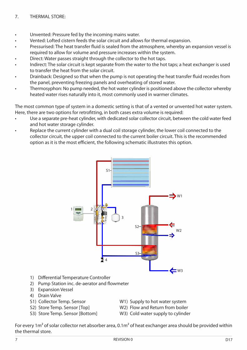
7. THERMAL STORE:
• Unvented: Pressure fed by the incoming mains water.• Vented: Lofted cistern feeds the solar circuit and allows for thermal expansion.• Pressurised: The heat transfer fluid is sealed from the atmosphere, whereby an expansion vessel is required to allow for volume and pressure increases within the system. • Direct: Water passes straight through the collector to the hot taps.• Indirect: The solar circuit is kept separate from the water to the hot taps; a heat exchanger is used to transfer the heat from the solar circuit.• Drainback: Designed so that when the pump is not operating the heat transfer fluid recedes from the panel, preventing freezing panels and overheating of stored water. • Thermosyphon: No pump needed, the hot water cylinder is positioned above the collector whereby heated water rises naturally into it, most commonly used in warmer climates.
The most common type of system in a domestic setting is that of a vented or unvented hot water system. Here, there are two options for retrofitting, in both cases extra volume is required: • Useaseparatepre-heatcylinder,withdedicatedsolarcollectorcircuit,betweenthecoldwaterfeed and hot water storage cylinder. • Replacethecurrentcylinderwithadualcoilstoragecylinder,thelowercoilconnectedtothe collector circuit, the upper coil connected to the current boiler circuit. This is the recommended option as it is the most efficient, the following schematic illustrates this option.
1) Differential Temperature Controller 2) Pump Station inc. de-aerator and flowmeter 3) Expansion Vessel 4) Drain Valve S1) Collector Temp. Sensor W1) Supply to hot water system S2) Store Temp. Sensor [Top] W2) Flow and Return from boiler S3) Store Temp. Sensor [Bottom] W3) Cold water supply to cylinder
For every 1m² of solar collector net absorber area, 0.1m² of heat exchanger area should be provided within the thermal store.
S1
S2
S3
1
3
2
4
W1
W2
W3
D17REVISION 07

8. STORAGE TANK SIZING:
• CalculatetheTotalStorageTankVolumeinLitres:ThetypicalfigureusedforDomesticHotWater consumption for a dwelling in the UK per person is 50 litres per day at 55°C.• MinimumStorageTankSize:140litres,inordertooperateatadecentlevelofefficiency.• CalculatewhichAEScollectortouse.Forevery60litresoftotalstoragetankvolumeallocate1m²of collector – using the gross area as the point of calculation. See table 2, rounding up to the nearest collector model for optimum system performance.• CalculationofDedicatedSolarVolume:Eachm²ofcollectorrequires25litresdedicatedsolar contribution (Vs) – use absorber area. See table 2. Figure also presented as a percentage of Vt – Total Storage Volume.
No. of persons in dwelling 1 2 3 4 5
Total DHW Cylinder Storage Volume litres @ 50 litres per person
(50) 140 (100) 140 150 200 250
Collector Sizing: 1m² per 60 litres of Total Storage Volume
Collector Size m² (1.97) 2.2 (2.17) 2.2 (2.17) 2.2 (2.98) 3.3 (3.95) 4.4
AES Collector (see table below) D / E D / E D / E H / I J / K
Solar Dedicated Volume (Vs): 25 litres Vs per m² of collector
Solar Dedicated Volume litres(% Vs of Vt)
49.5(35%)
54.5(39%)
54.5(36%)
74.6(37%)
98.8(40%)
Table 1: Calculations for 1 to 5 persons per dwelling
Model Gross Area m² Absorber Area m² Solar Dedicated Volume Litres(@ 25 litres per m²)
Total Volume Litres (@ 60 litres per m²)
A 1.2 0.98 24.7 60B & C 1.7 1.49 37.3 90D & E 2.2 1.97 49.5 120F & G 2.5 2.17 54.5 150H & I 3.3 2.98 74.6 180J & K 4.4 3.95 98.8 250
L (Bespoke) Any Any Any Any
Table 2: AES collector attributes
8REVISION 0D17

• Sizethesystemwithaviewtothefuturepotentialoccupancyrates,intheeventofhousesaleetc.• Observingdiagram2,withreferencetoorientationandpitchofthecollector,calculationsmayneed to be adjusted to take these factors into account.• Taketheavailableroofspaceintoaccount.AESproducevarioussizedcollectors,ensuringthereisa collector suitable whether in multiples or bespoke to fit. • Heavilyinsulatethestoragetanktomaximisesystemefficiency.
9. PIPE MATERIALS AND SIZES:
As temperatures within the solar circuit can exceed 100°C we recommend the use of copper or stainless steel tubing throughout the solar system circuit, do not use soft solder or plastic.
Within the solar circuit it is important that a flow speed of 1m/s is not exceeded. This will ensure that flow resistance within the pipes is maintained at a suitable level, whilst noise will also be kept to a minimum:
• Iftheflowspeedincreasesabove1m/sthenthenextpipesizeupisrequired.• Similarly,ifthepressuredroppermetreexceeds400Pascal/metrethenthesameactionmustbe taken.
With a pressure drop of 400 Pascal/metre (equivalent to a head loss of 0.04 metres per metre run (where mh = 10kPa)) and a flow speed of 1m/s the following flow rate limits are expected within each diameter of copper piping:
Pipe Diameter – mm 15 22 28 35 42 54
Max. flow rate permissible - litres per minute
4 12 25 50 75 125
Table 3: Pipe flow rate limits
The following pipe diameters (mm) are outline guidelines for pipe sizes for multiple collector arrays:
Collector Number of Collectors1 2 3 4 5
2.2m² 15 15 22 22 222.5m² 15 15 22 22 223.3m² 15 15 22 22 284.4m² 15 15 22 28 28
Table 4: Pipe diameters for multiple collector arrays
External pipework insulation must be UV resistant and reislient enough to
D17REVISION 09

10. PUMP SIZING:
Collectors become less efficient with increasing temperature, so the system needs to remove heat from the collectors at a sufficient rate. When specifying the pump, the total pressure loss within the solar circuit needs to be calculated, taking into account the pipe runs, fittings, glycol solution and the collector itself:
• Calculatethetotallengthofthepiperunwithinthesysteminmetres.• Multiplyby0.04(headlossinmetrespermetrerun).• Takethevariousfittingswithinthecircuitintoaccount;hereanassumptionof30%ofthetotalpipe run figure is taken i.e. multiply that figure by 1.3.• Consideringaglycolsolutionastheheattransferfluid,anassumptionof30%ofthepiperunand fittings together is taken i.e. multiply by 1.3, again.
((((Pipe Run in metres, m) x 0.04) x 1.3) x 1.3) = 0.0676m
• AddonthevaluefortheAEScollector-10kPaataflowrateof1.8litres/min/m², with the 60/40 water/glycol solution passing through.
When the total pressure loss and desired flow rate has been ascertained the pump can be sized and chosen: Pump manufacturers publish a characteristic curve for each pump they produce illustrating the parameters at which each pump will operate at its most efficient. Typically, the x-axis will illustrate the flow rate with the y-axis the pressure/head loss.
11. SAFETY EQUIPMENT:
Safety Relief Valve: Ascertain the maximum pressure rating of the weakest component in the system and set the valve to vent just below this level. For safety reasons site the vent in a safe position so as not to scald or burn persons.Pressure gauge: The pressure in the collector needs to be 0.5bar. Taking the geodetic height into account (max.10 metres) the pressure at the base of the system can reach 1.5bar @ 0.1bar per metre.Expansion Vessel: Thermal expansion of the transfer fluid will occur within the system when the collector is in operation. The purpose of the expansion vessel is to accommodate this extra volume without fluid being expelled, also ensuring that when the system does cool no air will be drawn into the system. The vessel itself contains a membrane that cannot withstand maximum collector temperatures of 130°C, therefore the positioning of the vessel is of paramount importance: Locate on the return leg to the collectors, off an uninsulated falling spur at a minimum distance of 0.5m. The solar thermal schematic on page 7 illustrates this ideal position.Expansion vessels are available in various sizes here: 18litres (minimum), 24litres, 35litres, 50litres and 80 litres. The following tables illustrate the expansion vessel sizes for various AES collectors (2.2m², 2.5m², 3.3m², 4.4m²)with varying fluid contents and static head heights. Total fluid content includes pipe runs, fittings and collectors. The exact calculations are indicated in brackets, with the appropriate expansion vessel chosen by rounding up to the nearest unit available in bold. The gas pre-charge of the expansion vessel should be conducted at the start of the commissioning process, before the glycol solution is flushed into the system.
Expansion Vessel Gas Pre-Charge Commission System Collectors Operating Diaghram Expands Diaghram Equilibrium Expansion Accomodated
10REVISION 0D17

2.2m² Collector:
No. of CollectorsTotal Fluid Content
Static Head, m Expansion Vessel Capacity, litres Gas side pre-charge, bar Initial Fill charge, bar
1/20
2.5 (9.38) 18 0.75 1.05
5 (9.92) 18 1 1.3
10 (11.2) 18 1.5 1.8
15 (12.8) 18 2 2.3
2/40
2.5 (14.6) 18 0.75 1.05
5 (15.5) 18 1 1.3
10 (17.5) 18 1.5 1.8
15 (20) 25 2 2.3
3/60
2.5 (19.9) 25 0.75 1.05
5 (21) 25 1 1.3
10 (23.7) 25 1.5 1.8
15 (27.2) 35 2 2.3
4/80
2.5 (25.1) 35 0.75 1.05
5 (26.6) 35 1 1.3
10 (30) 35 1.5 1.8
15 (34.4) 35 2 2.3
5/100
2.5 (30.4) 35 0.75 1.05
5 (32.1) 35 1 1.3
10 (36.3) 50 1.5 1.8
15 (41.6) 50 2 2.3
2.5m² Collector:
No. of CollectorsTotal Fluid Content
Static Head, m Expansion Vessel Capacity, litres Gas side pre-charge, bar Initial Fill charge, bar
1/20
2.5 (9.63) 18 0.75 1.05
5 (10.02) 18 1 1.3
10 (11.5) 18 1.5 1.8
15 (13.2) 18 2 2.3
2/40
2.5 (15.1) 18 0.75 1.05
5 (16) 18 1 1.3
10 (18) 18 1.5 1.8
15 (20.7) 25 2 2.3
3/60
2.5 (20.6) 25 0.75 1.05
5 (21.8) 25 1 1.3
10 (24.6) 25 1.5 1.8
15 (28.2) 35 2 2.3
4/80
2.5 (26.1) 35 0.75 1.05
5 (27.6) 35 1 1.3
10 (31.2) 35 1.5 1.8
15 (35.7) 50 2 2.3
5/100
2.5 (31.6) 35 0.75 1.05
5 (33.4) 35 1 1.3
10 (37.7) 50 1.5 1.8
15 (43.3) 50 2 2.3
D17REVISION 011

3.3m² Collector:
No. of CollectorsTotal Fluid Content
Static Head, m Expansion Vessel Capacity, litres Gas side pre-charge, bar Initial Fill charge, bar
1/20
2.5 (10.3) 18 0.75 1.05
5 (10.9) 18 1 1.3
10 (12.3) 18 1.5 1.8
15 (14.1) 18 2 2.3
2/40
2.5 (16.5) 18 0.75 1.05
5 (17.4) 18 1 1.3
10 (19.6) 25 1.5 1.8
15 (22.5) 25 2 2.3
3/60
2.5 (22.6) 25 0.75 1.05
5 (23.9) 25 1 1.3
10 (27) 35 1.5 1.8
15 (30.9) 35 2 2.3
4/80
2.5 (28.8) 35 0.75 1.05
5 (30.4) 35 1 1.3
10 (34.3) 35 1.5 1.8
15 (39.4) 50 2 2.3
5/100
2.5 (34.9) 35 0.75 1.05
5 (36.9) 50 1 1.3
10 (41.7) 50 1.5 1.8
15 (47.8) 50 2 2.3
4.4m² Collector:
No. of CollectorsTotal Fluid Content
Static Head, m Expansion Vessel Capacity, litres Gas side pre-charge, bar Initial Fill charge, bar
1/20
2.5 (11.2) 18 0.75 1.05
5 (11.8) 18 1 1.3
10 (13.4) 18 1.5 1.8
15 (15.3) 18 2 2.3
2/40
2.5 (18.3) 25 0.75 1.05
5 (19.3) 25 1 1.3
10 (21.8) 25 1.5 1.8
15 (25) 25 2 2.3
3/60
2.5 (25.3) 35 0.75 1.05
5 (26.8) 35 1 1.3
10 (30.2) 35 1.5 1.8
15 (34.7) 35 2 2.3
4/80
2.5 (32.4) 35 0.75 1.05
5 (34.3) 35 1 1.3
10 (38.6) 50 1.5 1.8
15 (44.3) 50 2 2.3
5/100
2.5 (39.5) 50 0.75 1.05
5 (41.7) 50 1 1.3
10 (47.1) 50 1.5 1.8
15 (54) 80 2 2.3
12REVISION 0D17

12. FREEZE PROTECTION:
A 60/40 water to glycol solution is used as the transfer fluid within the solar circuit to ensure no freezing occurs. This fluid is capable of withstanding temperatures between -20°C and 200°C.
13. LEGIONELLA PROTECTION:
Legionella bacteria proliferates between 20°C and 45°C. It is therefore important that solar water heating systems have an auxiliary means of raising the temperature to at least 60°C during winter months or days with little solar availability. To ensure appropriate sterilisation of the cylinder use the following formula to calculate the minimum time an auxillary heating unit needs to be in operation:
Operation time, mins =
14. LIMESCALE PREVENTION:
The high temperatures experienced in solar cylinders can result in the accumulation of limescale in hard water areas. As a means of control, the differential controller can be set with a maximum store tempera-ture of 60°C. Limescale build-up will not occur within the closed loop of an indirect solar circuit.
15. SENSOR POSITIONING:
Fit temperature sensors securely into the housing of the collector and storage cylinder. Push them in by 120mm and secure them in place either with a suitable sealant or within a dedicated sensor probe.
(Cylinder capacity in litres x 4.2) kW
D17REVISION 013

16. GLOSSARY:
Global Solar Radiation: The sum of both the direct and diffused elements of solar radiation meeting on a horizontal surface. Readings are measured in mega joules per square metre.Direct Solar Radiation: The term attributed to the solar radiation that directly hits the earth’s surface having met no obstacles; it is this light that casts straight line shadows.Diffuse Solar Radiation: This form of radiation reaches the earth’s surface having hit particles and moisture in the atmosphere, forc-ing it to scatter downwards. Even on very clear days this portion can be around 10% of the total radiation meeting the surface.Stagnation: When the pump is not in operation and there is no movement in the transfer fluid, the collector is in a state of stagnation. If there is sufficient solar radiation falling upon the absorber plate then very high temperatures will be generated at the collector. Flat Plate Collector: Flat bed panel containing the absorber plate either in a serpentine or header and riser configuration depend-ing on application. Absorber Plate: AES utilise a tube-in-fin absorber plate arrangement. The fins, which absorb the solar radiation, are metal-lurgically bonded to the copper piping for excellent heat transfer characteristics.Absorber Plate Coating: The AES absorber plate incorporates an advanced coating that increases its capacity to absorb solar radia-tion.Glazing: The weatherproof membrane seperating the absorber plate from the outside envrinoment. AES use a twin-wall polycarbonate sheeting to optimise the transfer of solar radiation to heat.Hot Water Cylinder: For storing the heated water, come in a variety of different configurations.Differential Temperature Controller: Controls the flow of the heat transfer fluid around the solar circuit by managing the various temperature sensors located throughout.Pump Station: Circulates the heat transfer fluid about the solar system circuit. Flow-Meter: Incorporates a flow-measuring device and a flow regulation valve to adjust the rate at which a fluid will pass through the solar circuit.Non-return Valve: A one-way valve mounted in the system to prevent thermosyphoning when the pump is off, for best results mount one in the flow leg and one in the return leg. Air Vent: To rid the system of any unwanted air - mount at the highest point and as close to the collector as possible.Pressure Relief Valve and Pressure Gauge: In a sealed system it is essential that a relief valve is incorporated to prevent damage to components.Flow gauge: To measure the rate of flow around the circuit. Expansion Vessel: Allows for thermal expansion and pressure increases within the system.Drain Valve: Fit at lowest point in the system.
14REVISION 0D17

AES LtdLea Road
ForresIV36 1AU
T. +44 (0)1309 676911F. +44 (0)1309 671086E. [email protected]. www.aessolar.co.uk