technical manual - aptargroup · finishes. snap bead shoulder. technical manual. 12 of 37 . 3.0...
TRANSCRIPT
Technical ManualThis technical manual has been prepared to assist in the understanding and use of the dispensing closures manufactured by Aptar.
Included in this manual is basic information on dispensing closure design, function, materials, specifications, product compatibility, application, and other information that should be taken into consideration when making packaging and closure decisions.
This manual is intended to answer general and frequently asked questions. For complete details about specific closures, designs, and applications please consult the experts at Aptar.
The information on these pages is offered in good faith by Aptar. Aptar makes no warranty of any type, expressed or implied, regarding any information set forth in this manual. Always consult the experts at Aptar for your specific requirements.
1 of 37
Technical Manual 2 of 37
Table of Contents1.0 Closure types
1.1 Snap Top® Closures page 3 1.2 Disc Top® Closures page 41.3 Double Wall Closures page 61.4 Closures with Valves page 7
2.0 Critical Dimensions2.1 Threaded Closures page 92.2 Threaded Bottles page 102.3 Snap-on Closures page 112.4 Snap-on Bottles page 12
3.0 Orientation of Threaded Closure page 13
4.0 Closure Thread Profiles page 15
5.0 Closure to Bottle Seal Systems5.1 Crab Claw Seal page 165.2 Flat Seal page 175.3 Plug Seal page 185.4 V-seal page 19
6.0 Closure Orifice Seals6.1 Collar seal page 206.2 Spud and Orifice page 21
7.0 Biased Hinges7.1 Butterfly Hinges
and Dual Axis Hinges page 227.2 Strap Hinges page 23
8.0 Opening Force page 248.1 Latch Beads page 25
9.0 Application Torque page 26
10.0 Plastic Materials page 27
11.0 Plastic Additives11.1 Anti-stat page 2811.2 Colorant page 29
12.0 Product & Chemical Compatibility page 30
13.0 Liners and Inner Seals page 31
14.0 Glossary of Terms page 32
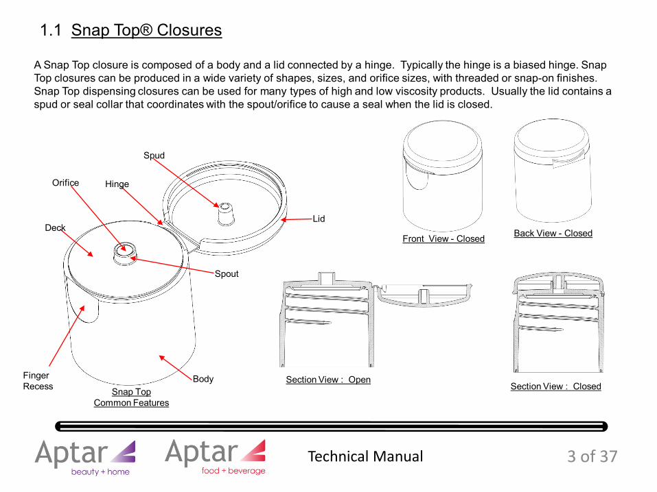
A Snap Top closure is composed of a body and a lid connected by a hinge. Typically the hinge is a biased hinge. Snap Top closures can be produced in a wide variety of shapes, sizes, and orifice sizes, with threaded or snap-on finishes. Snap Top dispensing closures can be used for many types of high and low viscosity products. Usually the lid contains a spud or seal collar that coordinates with the spout/orifice to cause a seal when the lid is closed.
1.1 Snap Top® Closures
Lid
Body
Spud
Orifice Hinge
Finger Recess
Deck
Section View : OpenSection View : Closed
Front View - Closed Back View - Closed
Snap Top Common Features
Spout
3 of 37 Technical Manual
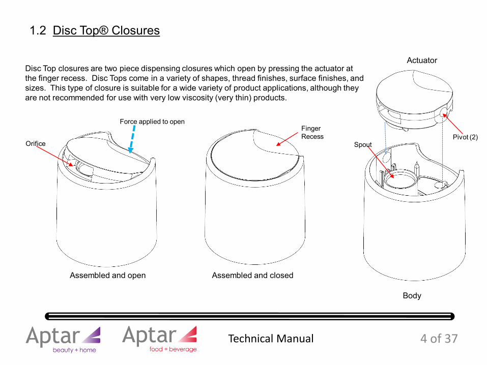
Disc Top closures are two piece dispensing closures which open by pressing the actuator at the finger recess. Disc Tops come in a variety of shapes, thread finishes, surface finishes, and sizes. This type of closure is suitable for a wide variety of product applications, although they are not recommended for use with very low viscosity (very thin) products.
1.2 Disc Top® Closures
Body
Actuator
Assembled and closedAssembled and open
Force applied to open
Orifice
Finger Recess
SpoutPivot (2)
4 of 37 Technical Manual
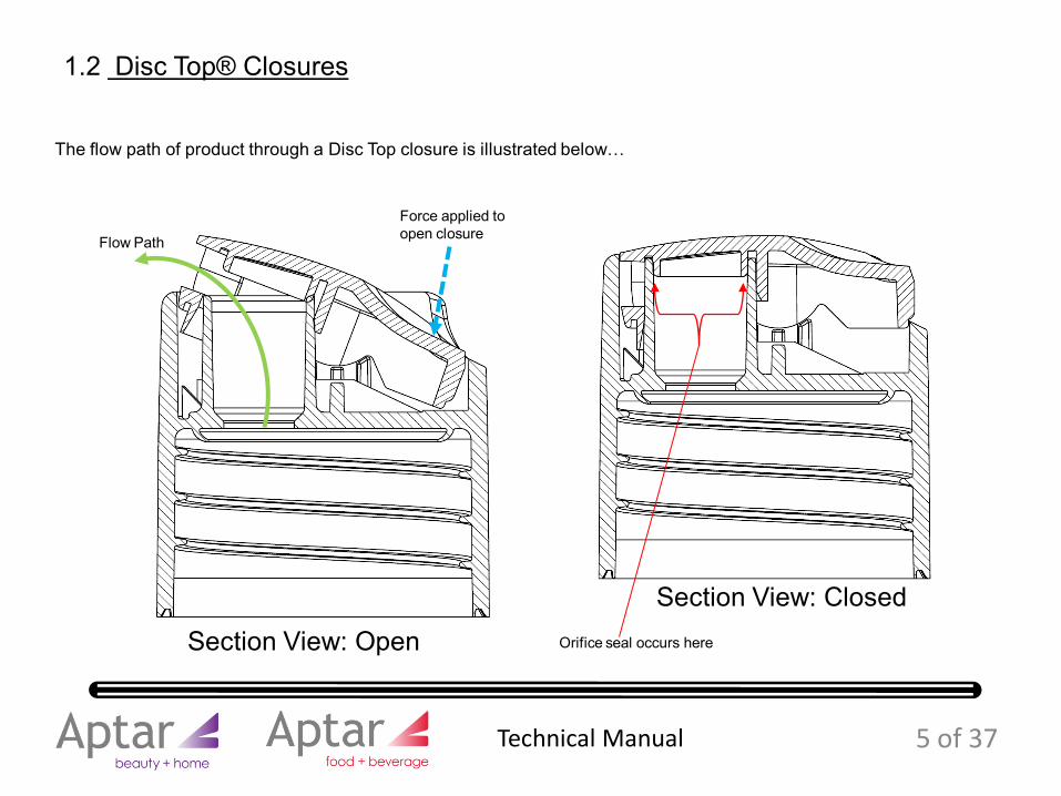
The flow path of product through a Disc Top closure is illustrated below…
1.2 Disc Top® Closures
Force applied to open closureFlow Path
Section View: Closed
Section View: Open Orifice seal occurs here
5 of 37 Technical Manual
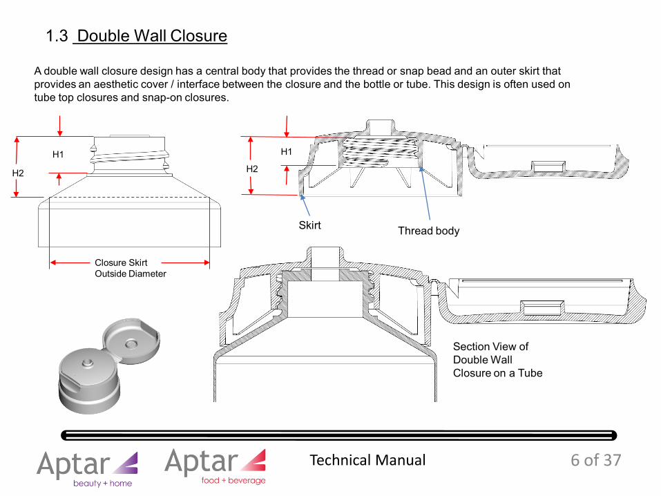
A double wall closure design has a central body that provides the thread or snap bead and an outer skirt that provides an aesthetic cover / interface between the closure and the bottle or tube. This design is often used on tube top closures and snap-on closures.
1.3 Double Wall Closure
Thread bodySkirt
Section View of Double Wall Closure on a Tube
H1
H2H2
H1
Closure Skirt Outside Diameter
6 of 37 Technical Manual
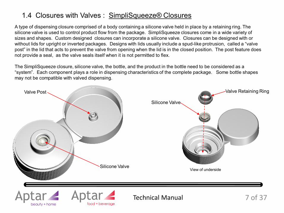
A type of dispensing closure comprised of a body containing a silicone valve held in place by a retaining ring. The silicone valve is used to control product flow from the package. SimpliSqueeze closures come in a wide variety of sizes and shapes. Custom designed closures can incorporate a silicone valve. Closures can be designed with or without lids for upright or inverted packages. Designs with lids usually include a spud-like protrusion, called a “valve post” in the lid that acts to prevent the valve from opening when the lid is in the closed position. The post feature does not provide a seal, as the valve seals itself when it is not permitted to flex.
The SimpliSqueeze closure, silicone valve, the bottle, and the product in the bottle need to be considered as a “system”. Each component plays a role in dispensing characteristics of the complete package. Some bottle shapes may not be compatible with valved dispensing.
1.4 Closures with Valves : SimpliSqueeze® Closures
Valve Retaining Ring
Silicone Valve
Silicone Valve
Valve Post
7 of 37
View of underside
Technical Manual
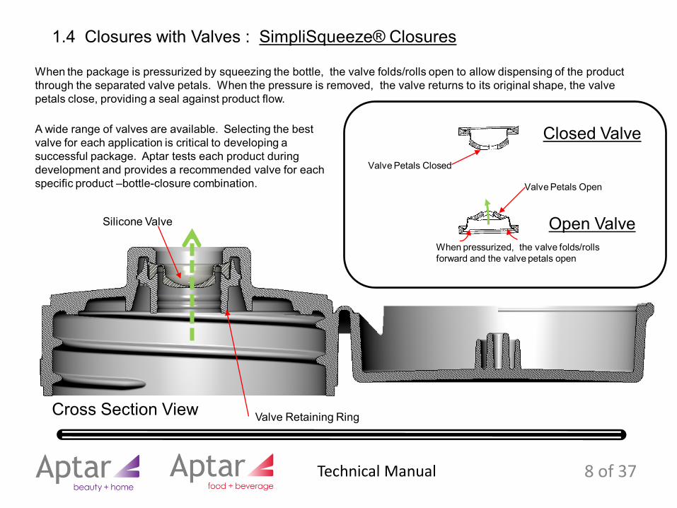
When the package is pressurized by squeezing the bottle, the valve folds/rolls open to allow dispensing of the product through the separated valve petals. When the pressure is removed, the valve returns to its original shape, the valve petals close, providing a seal against product flow.
Valve Retaining Ring
Silicone Valve
Closed Valve
Open Valve
Valve Petals Open
Valve Petals Closed
Cross Section View
When pressurized, the valve folds/rolls forward and the valve petals open
A wide range of valves are available. Selecting the best valve for each application is critical to developing a successful package. Aptar tests each product during development and provides a recommended valve for each specific product –bottle-closure combination.
8 of 37
1.4 Closures with Valves : SimpliSqueeze® Closures
Technical Manual
E diameter
T diameter
H
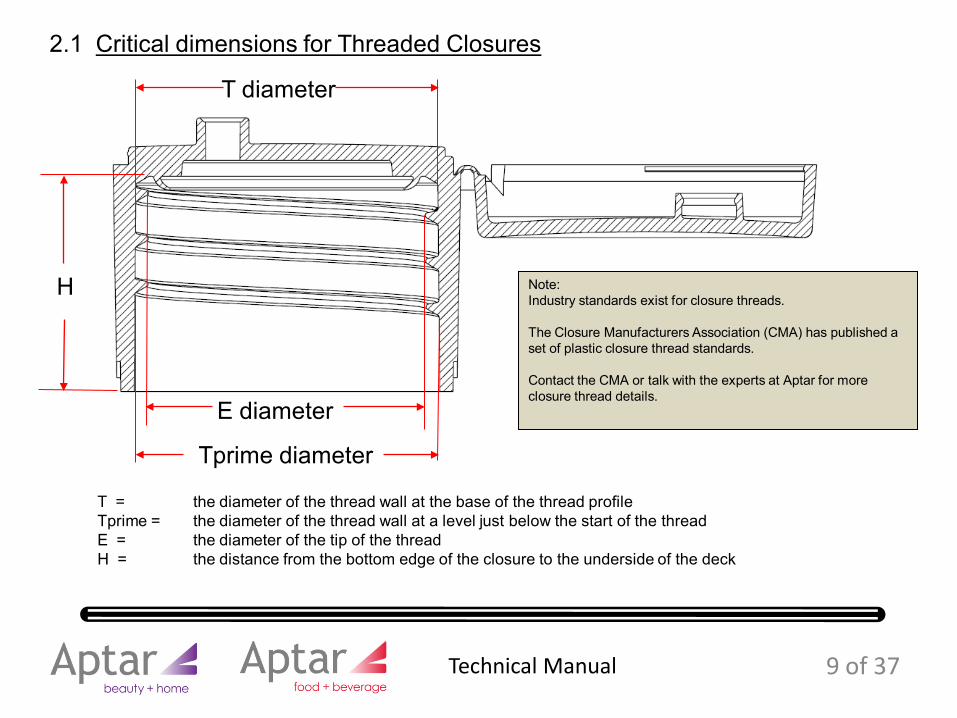
T = the diameter of the thread wall at the base of the thread profileTprime = the diameter of the thread wall at a level just below the start of the threadE = the diameter of the tip of the threadH = the distance from the bottom edge of the closure to the underside of the deck
Tprime diameter
2.1 Critical dimensions for Threaded Closures
Note:Industry standards exist for closure threads.
The Closure Manufacturers Association (CMA) has published a set of plastic closure thread standards.
Contact the CMA or talk with the experts at Aptar for more closure thread details.
9 of 37 Technical Manual
E diameter
T diameter
H
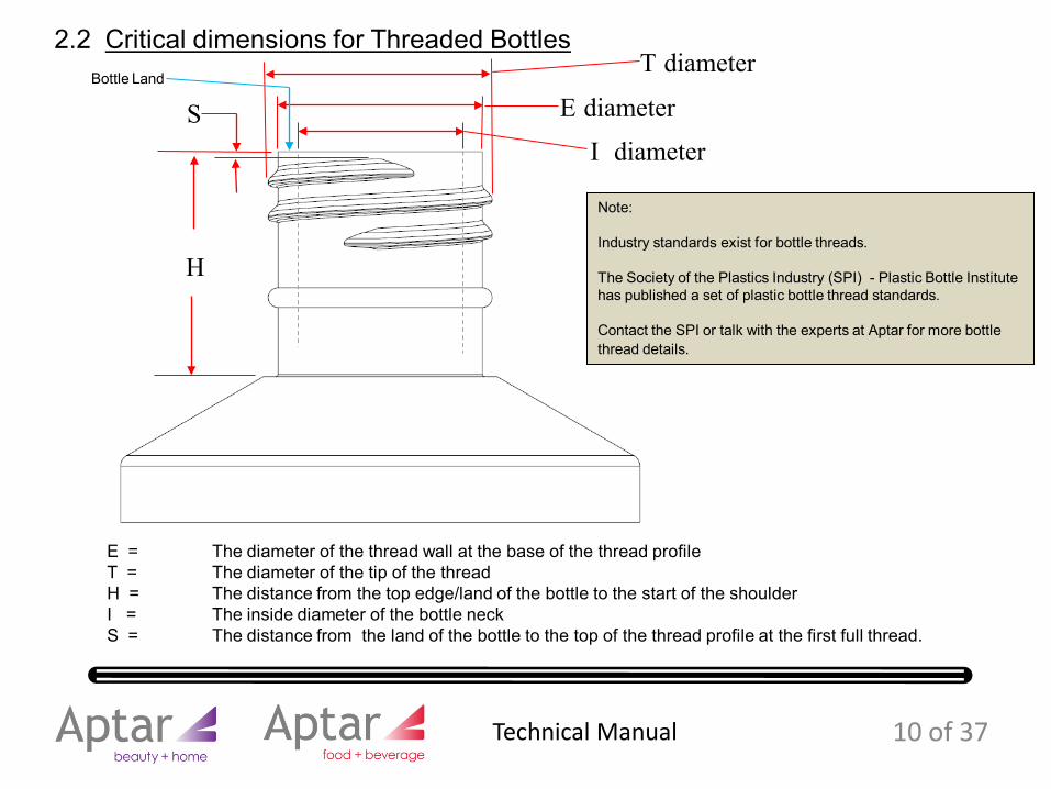
E = The diameter of the thread wall at the base of the thread profileT = The diameter of the tip of the threadH = The distance from the top edge/land of the bottle to the start of the shoulderI = The inside diameter of the bottle neckS = The distance from the land of the bottle to the top of the thread profile at the first full thread.
2.2 Critical dimensions for Threaded Bottles
I diameter
Note:
Industry standards exist for bottle threads.
The Society of the Plastics Industry (SPI) - Plastic Bottle Institute has published a set of plastic bottle thread standards.
Contact the SPI or talk with the experts at Aptar for more bottle thread details.
SBottle Land
10 of 37 Technical Manual
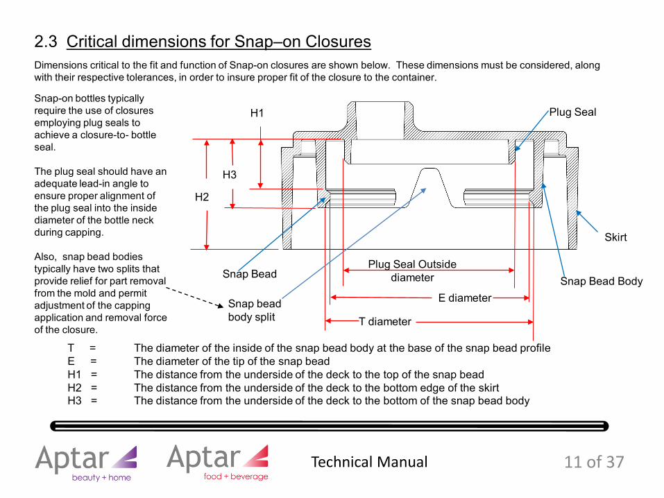
Dimensions critical to the fit and function of Snap-on closures are shown below. These dimensions must be considered, along with their respective tolerances, in order to insure proper fit of the closure to the container.
2.3 Critical dimensions for Snap–on Closures
H1
H3
H2
Plug Seal Outside diameter
T diameter
E diameter
T = The diameter of the inside of the snap bead body at the base of the snap bead profileE = The diameter of the tip of the snap beadH1 = The distance from the underside of the deck to the top of the snap beadH2 = The distance from the underside of the deck to the bottom edge of the skirtH3 = The distance from the underside of the deck to the bottom of the snap bead body
Snap-on bottles typically require the use of closures employing plug seals to achieve a closure-to- bottle seal.
The plug seal should have an adequate lead-in angle to ensure proper alignment of the plug seal into the inside diameter of the bottle neck during capping.
Also, snap bead bodies typically have two splits that provide relief for part removal from the mold and permit adjustment of the capping application and removal force of the closure.
Snap Bead Body
Skirt
Plug Seal
Snap Bead
Snap bead body split
11 of 37 Technical Manual
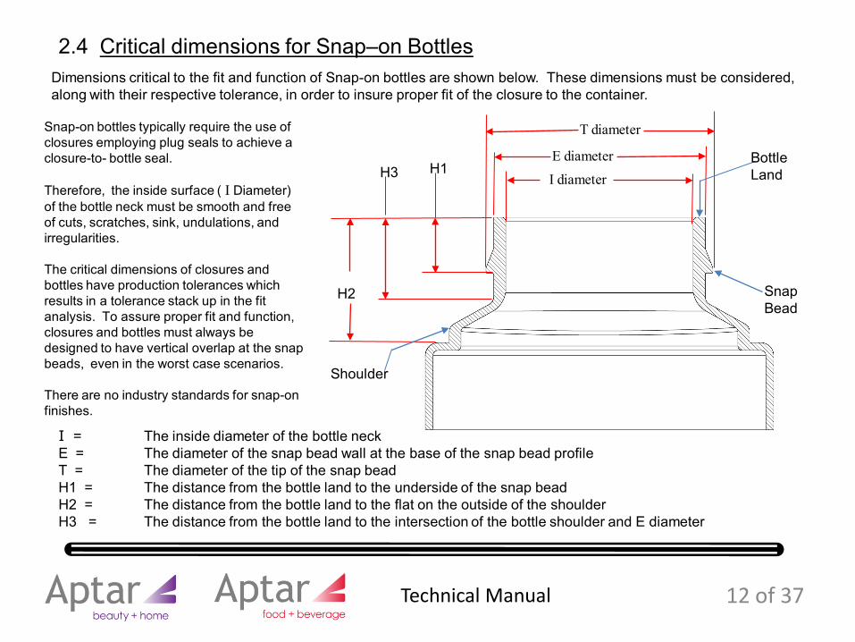
Dimensions critical to the fit and function of Snap-on bottles are shown below. These dimensions must be considered, along with their respective tolerance, in order to insure proper fit of the closure to the container.
2.4 Critical dimensions for Snap–on Bottles
H1
H2
H3
T diameter
E diameter
I diameterBottle Land
I = The inside diameter of the bottle neckE = The diameter of the snap bead wall at the base of the snap bead profileT = The diameter of the tip of the snap beadH1 = The distance from the bottle land to the underside of the snap beadH2 = The distance from the bottle land to the flat on the outside of the shoulderH3 = The distance from the bottle land to the intersection of the bottle shoulder and E diameter
Snap-on bottles typically require the use of closures employing plug seals to achieve a closure-to- bottle seal.
Therefore, the inside surface ( I Diameter) of the bottle neck must be smooth and free of cuts, scratches, sink, undulations, and irregularities.
The critical dimensions of closures and bottles have production tolerances which results in a tolerance stack up in the fit analysis. To assure proper fit and function, closures and bottles must always be designed to have vertical overlap at the snap beads, even in the worst case scenarios.
There are no industry standards for snap-on finishes.
SnapBead
Shoulder
12 of 37 Technical Manual
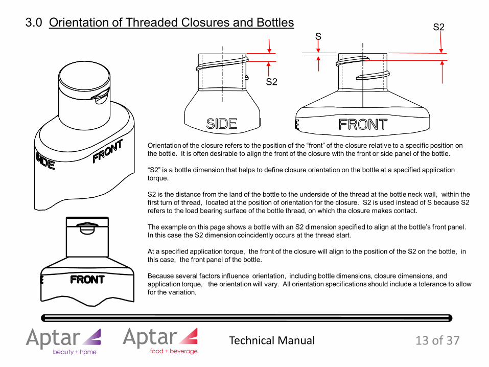
3.0 Orientation of Threaded Closures and Bottles
Orientation of the closure refers to the position of the “front” of the closure relative to a specific position on the bottle. It is often desirable to align the front of the closure with the front or side panel of the bottle.
“S2” is a bottle dimension that helps to define closure orientation on the bottle at a specified application torque.
S2 is the distance from the land of the bottle to the underside of the thread at the bottle neck wall, within the first turn of thread, located at the position of orientation for the closure. S2 is used instead of S because S2 refers to the load bearing surface of the bottle thread, on which the closure makes contact.
The example on this page shows a bottle with an S2 dimension specified to align at the bottle’s front panel. In this case the S2 dimension coincidently occurs at the thread start.
At a specified application torque, the front of the closure will align to the position of the S2 on the bottle, in this case, the front panel of the bottle.
Because several factors influence orientation, including bottle dimensions, closure dimensions, and application torque, the orientation will vary. All orientation specifications should include a tolerance to allow for the variation.
S2
S2
S
13 of 37 Technical Manual
S2S2
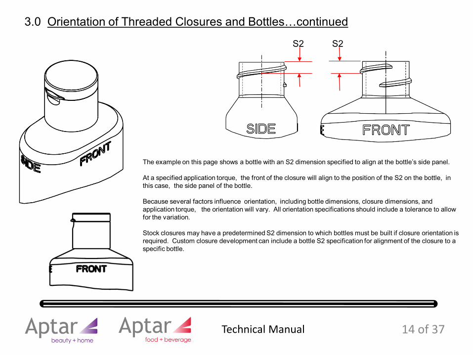
The example on this page shows a bottle with an S2 dimension specified to align at the bottle’s side panel.
At a specified application torque, the front of the closure will align to the position of the S2 on the bottle, in this case, the side panel of the bottle.
Because several factors influence orientation, including bottle dimensions, closure dimensions, and application torque, the orientation will vary. All orientation specifications should include a tolerance to allow for the variation.
Stock closures may have a predetermined S2 dimension to which bottles must be built if closure orientation is required. Custom closure development can include a bottle S2 specification for alignment of the closure to a specific bottle.
14 of 37
3.0 Orientation of Threaded Closures and Bottles…continued
Technical Manual
E diameter
T diameter
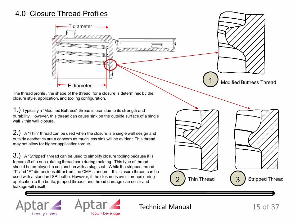
4.0 Closure Thread Profiles
The thread profile , the shape of the thread, for a closure is determined by the closure style, application, and tooling configuration.
1.) Typically a “Modified Buttress” thread is use due to its strength and durability. However, this thread can cause sink on the outside surface of a single wall / thin wall closure.
2.) A “Thin” thread can be used when the closure is a single wall design and outside aesthetics are a concern as much less sink will be evident. This thread may not allow for higher application torque.
3.) A “Stripped” thread can be used to simplify closure tooling because it is forced off of a non-rotating thread core during molding. This type of thread should be employed in conjunction with a plug seal. While the stripped thread “T” and “E” dimensions differ from the CMA standard, this closure thread can be used with a standard SPI bottle. However, if the closure is over-torqued during application to the bottle, jumped threads and thread damage can occur and leakage will result.
Modified Buttress Thread
Stripped ThreadThin Thread
1
2 3
15 of 37 Technical Manual
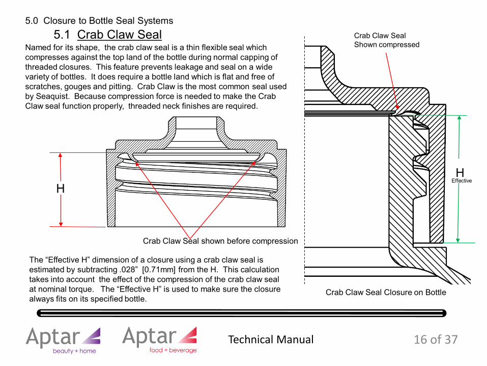
5.0 Closure to Bottle Seal Systems
Crab Claw Seal shown before compression
Crab Claw SealShown compressed
Crab Claw Seal Closure on Bottle
Named for its shape, the crab claw seal is a thin flexible seal which compresses against the top land of the bottle during normal capping of threaded closures. This feature prevents leakage and seal on a wide variety of bottles. It does require a bottle land which is flat and free of scratches, gouges and pitting. Crab Claw is the most common seal used by Seaquist. Because compression force is needed to make the Crab Claw seal function properly, threaded neck finishes are required.
5.1 Crab Claw Seal
The “Effective H” dimension of a closure using a crab claw seal is estimated by subtracting .028” [0.71mm] from the H. This calculation takes into account the effect of the compression of the crab claw seal at nominal torque. The “Effective H” is used to make sure the closure always fits on its specified bottle.
HH
Effective
16 of 37 Technical Manual
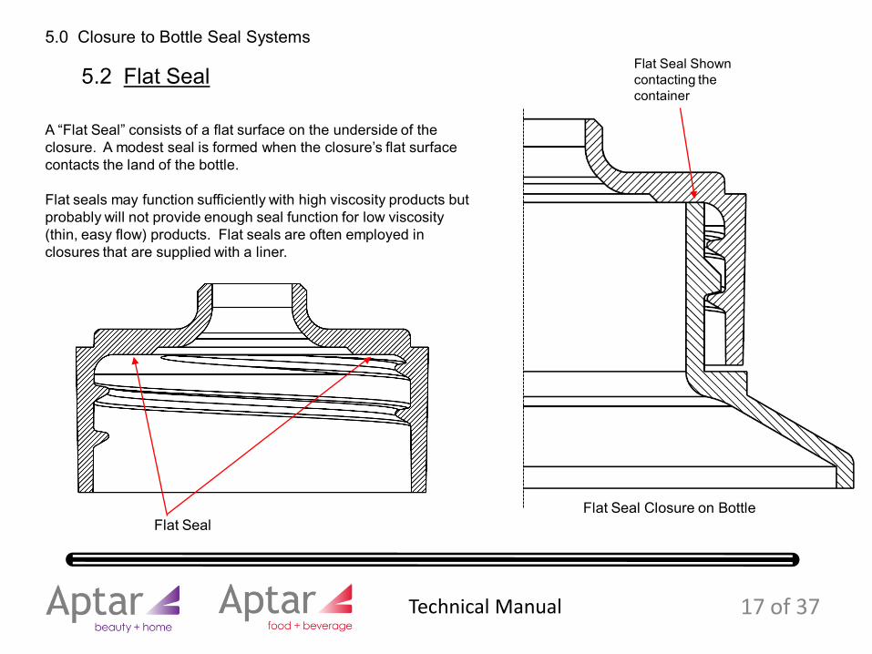
Flat Seal
Flat Seal Shown contacting the container
Flat Seal Closure on Bottle
A “Flat Seal” consists of a flat surface on the underside of the closure. A modest seal is formed when the closure’s flat surface contacts the land of the bottle.
Flat seals may function sufficiently with high viscosity products but probably will not provide enough seal function for low viscosity (thin, easy flow) products. Flat seals are often employed in closures that are supplied with a liner.
5.2 Flat Seal
17 of 37
5.0 Closure to Bottle Seal Systems
Technical Manual
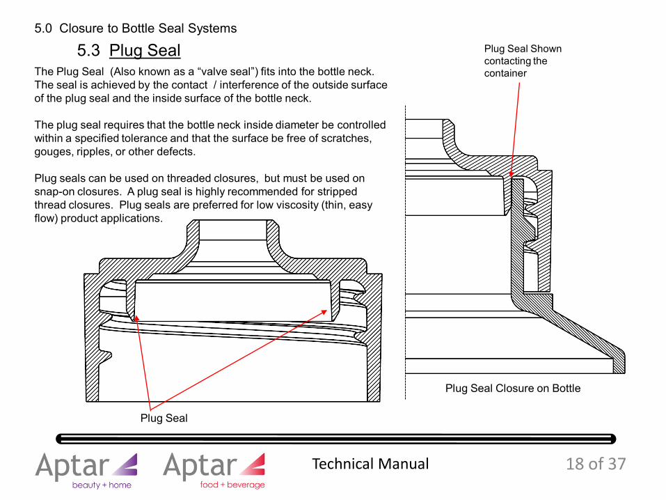
Plug Seal
Plug Seal Shown contacting the container
Plug Seal Closure on Bottle
The Plug Seal (Also known as a “valve seal”) fits into the bottle neck. The seal is achieved by the contact / interference of the outside surface of the plug seal and the inside surface of the bottle neck.
The plug seal requires that the bottle neck inside diameter be controlled within a specified tolerance and that the surface be free of scratches, gouges, ripples, or other defects.
Plug seals can be used on threaded closures, but must be used on snap-on closures. A plug seal is highly recommended for stripped thread closures. Plug seals are preferred for low viscosity (thin, easy flow) product applications.
5.3 Plug Seal
18 of 37
5.0 Closure to Bottle Seal Systems
Technical Manual
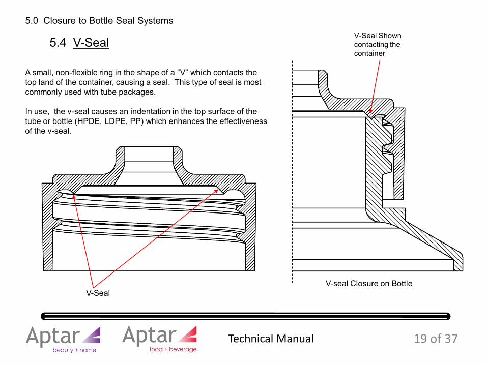
V-Seal
V-Seal Shown contacting the container
V-seal Closure on Bottle
A small, non-flexible ring in the shape of a “V” which contacts the top land of the container, causing a seal. This type of seal is most commonly used with tube packages.
In use, the v-seal causes an indentation in the top surface of the tube or bottle (HPDE, LDPE, PP) which enhances the effectiveness of the v-seal.
5.4 V-Seal
19 of 37
5.0 Closure to Bottle Seal Systems
Technical Manual
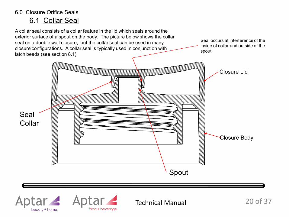
6.0 Closure Orifice Seals
Seal occurs at interference of the inside of collar and outside of the spout.
A collar seal consists of a collar feature in the lid which seals around the exterior surface of a spout on the body. The picture below shows the collar seal on a double wall closure, but the collar seal can be used in many closure configurations. A collar seal is typically used in conjunction with latch beads (see section 8.1)
6.1 Collar Seal
SealCollar
Spout
Closure Lid
Closure Body
20 of 37 Technical Manual
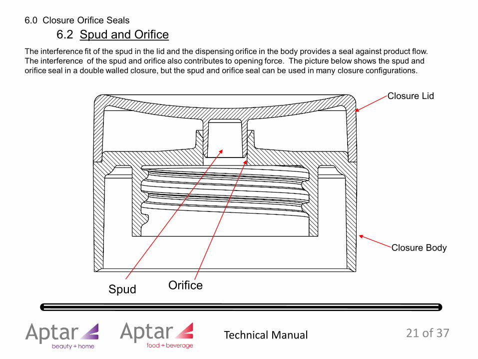
The interference fit of the spud in the lid and the dispensing orifice in the body provides a seal against product flow. The interference of the spud and orifice also contributes to opening force. The picture below shows the spud and orifice seal in a double walled closure, but the spud and orifice seal can be used in many closure configurations.
6.2 Spud and Orifice
Spud Orifice
Closure Lid
Closure Body
21 of 37
6.0 Closure Orifice Seals
Technical Manual
7.0 Biased Hinges
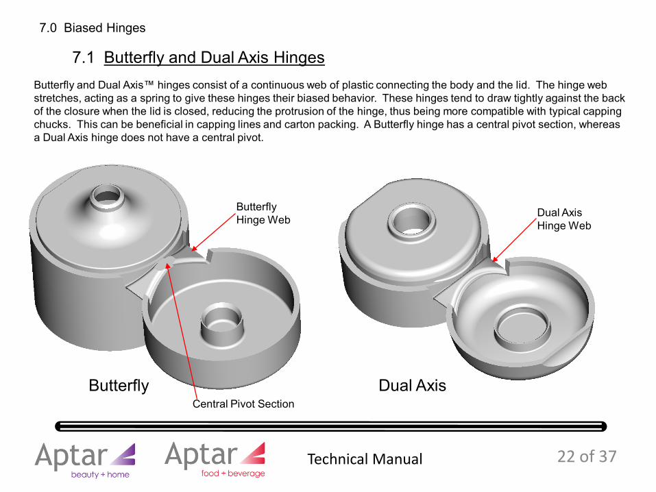
Butterfly and Dual Axis™ hinges consist of a continuous web of plastic connecting the body and the lid. The hinge web stretches, acting as a spring to give these hinges their biased behavior. These hinges tend to draw tightly against the backof the closure when the lid is closed, reducing the protrusion of the hinge, thus being more compatible with typical capping chucks. This can be beneficial in capping lines and carton packing. A Butterfly hinge has a central pivot section, whereas a Dual Axis hinge does not have a central pivot.
7.1 Butterfly and Dual Axis Hinges
Butterfly Dual Axis
Dual AxisHinge Web
ButterflyHinge Web
Central Pivot Section
22 of 37 Technical Manual
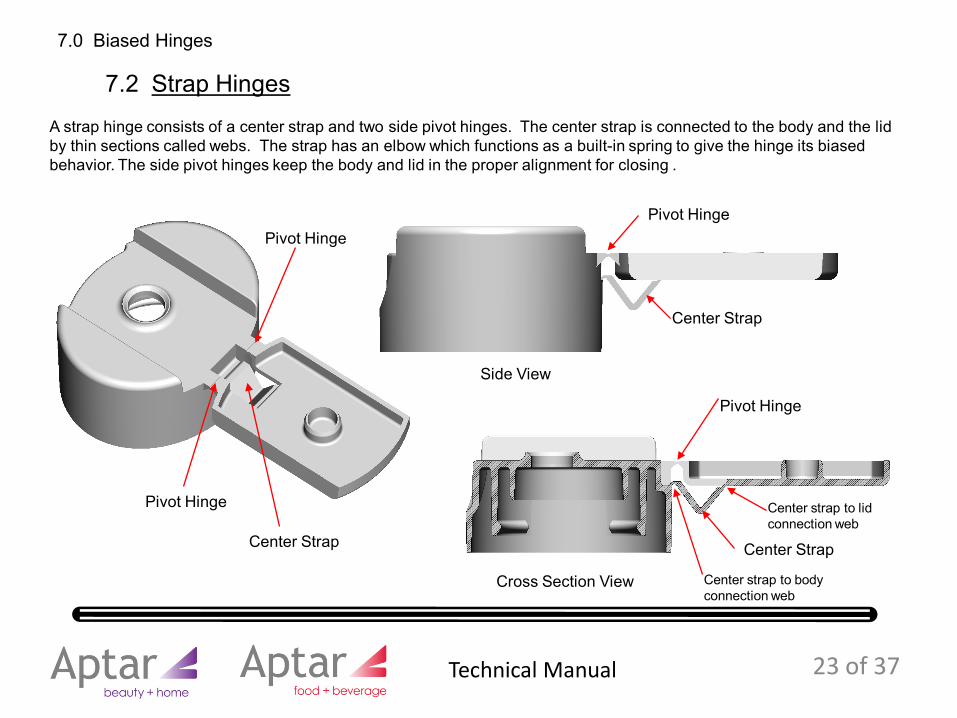
A strap hinge consists of a center strap and two side pivot hinges. The center strap is connected to the body and the lid by thin sections called webs. The strap has an elbow which functions as a built-in spring to give the hinge its biased behavior. The side pivot hinges keep the body and lid in the proper alignment for closing .
Pivot Hinge
Pivot Hinge
Center Strap
Pivot Hinge
Pivot Hinge
Center Strap
Center Strap
Cross Section View
Side View
23 of 37
7.0 Biased Hinges
7.2 Strap Hinges
Center strap to lid connection web
Center strap to body connection web
Technical Manual
In Snap Top (hinged lid) closures, the amount of force required to open the lid is referred to as opening force or “lift”. Each hinge closure design has a specified opening force which is monitored during production to ensure the closures are within the specification.
In Disc Top closures the opening force (downward force on the actuator) is referred to as “actuation force”.
The Opening Force needs to be low enough for people to be able to open the closure, but high enough to keep the closure closed during transit, handling , capping, and distribution. Opening force requirements may be different for different size closures.
When measuring opening force or actuation force, the closure must be applied to an appropriate test fixture at a specified application torque.
Some of the major factors which can effect opening force or actuation force include:• Resin selection• Colorants• Processing additives• Processing parameters• Application torque• Closure temperature• Product in orifice• Orifice diameter• Spud/orifice or Spout/collar design in Snap Tops• Actuation ribs in Disc Tops
8.0 Opening Force
The opening force specification on any closure includes a tolerance range to account for normal variations in the plastic parts. Please consult the experts at Aptar for specific opening force requirements and performance characteristics.
24 of 37 Technical Manual
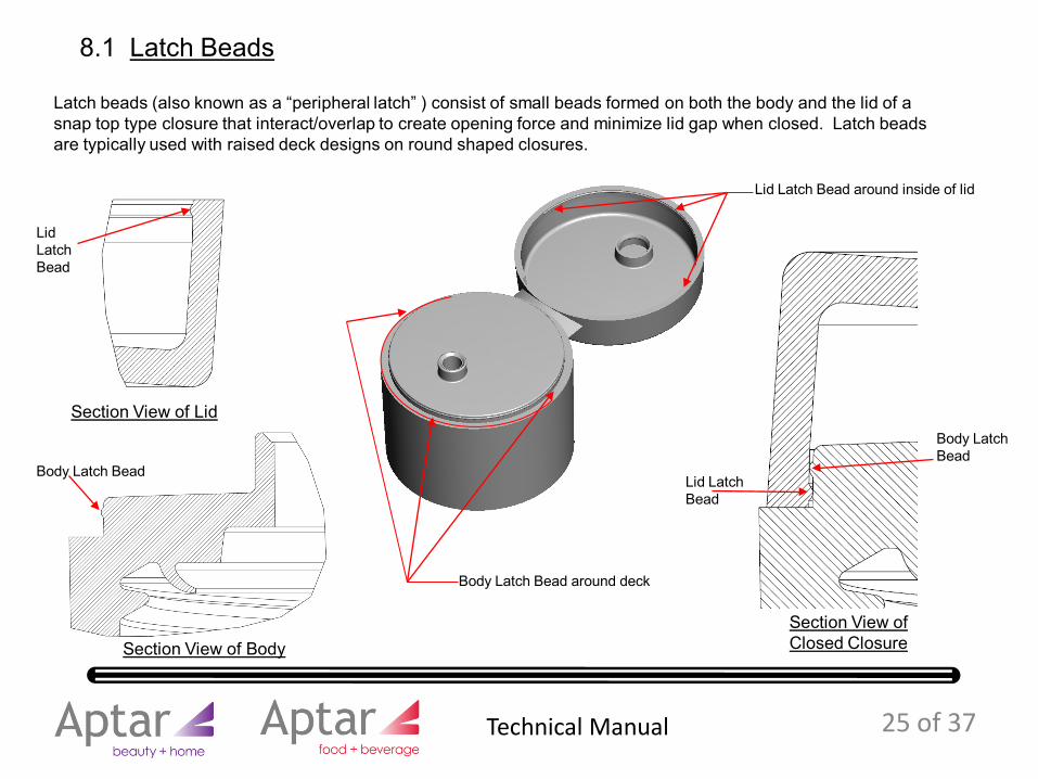
Latch beads (also known as a “peripheral latch” ) consist of small beads formed on both the body and the lid of a snap top type closure that interact/overlap to create opening force and minimize lid gap when closed. Latch beads are typically used with raised deck designs on round shaped closures.
8.1 Latch Beads
Section View of Lid
Section View of BodySection View of Closed Closure
Body Latch Bead
Lid Latch Bead
Body Latch Bead
Lid Latch Bead
Body Latch Bead around deck
Lid Latch Bead around inside of lid
25 of 37 Technical Manual
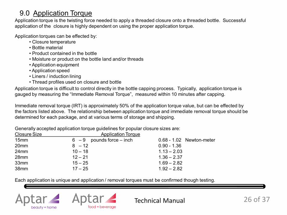
Application torque is the twisting force needed to apply a threaded closure onto a threaded bottle. Successful application of the closure is highly dependent on using the proper application torque.
Application torques can be effected by:• Closure temperature• Bottle material• Product contained in the bottle• Moisture or product on the bottle land and/or threads• Application equipment• Application speed• Liners / induction lining• Thread profiles used on closure and bottle
9.0 Application Torque
Application torque is difficult to control directly in the bottle capping process. Typically, application torque is gauged by measuring the “Immediate Removal Torque”, measured within 10 minutes after capping.
Immediate removal torque (IRT) is approximately 50% of the application torque value, but can be effected by the factors listed above. The relationship between application torque and immediate removal torque should be determined for each package, and at various terms of storage and shipping.
Generally accepted application torque guidelines for popular closure sizes are:Closure Size Application Torque 15mm 6 – 9 pounds force – inch 0.68 - 1.02 Newton-meter20mm 8 – 12 0.90 - 1.3624mm 10 – 18 1.13 – 2.0328mm 12 – 21 1.36 – 2.3733mm 15 – 25 1.69 – 2.82 38mm 17 – 25 1.92 – 2.82
Each application is unique and application / removal torques must be confirmed though testing.
26 of 37 Technical Manual

Polypropylene is the thermoplastic polymer used for injection molding dispensing closures. The physical properties of polypropylene make it durable and allow it to function well in living hinges, often employed in dispensing closures.
Aptar uses homopolymer and copolymer polypropylenes in the manufacture of dispensing closures.
Homopolymer is 100% polypropylene plastic .
Copolymer is a blend of polypropylene plastic and a small amount of polyethylene plastic.
Generally, homopolymers are recommended for dispensing closures. Copolymers should be used for refrigerated products or where increased impact resistance is needed.
There are a variety of polypropylenes available for use in dispensing closures.
Material selection is an important step in the design, manufacture and use of dispensing closures. A complete understanding of the product requirements, end use environment, shipping requirements and chemical compatibility is needed when selecting a plastic for a closure. Each application must consider these factors as product performance will depend on the material’s properties.
Aptar’s stock products are produced in polypropylene plastics selected by Aptar for their performance and availability. Custom closures sometimes use unique polypropylene although at an increased cost.
10.0 Plastic Materials
27 of 37 Technical Manual
Additives are used to modify the characteristics of the plastics used in molding closures in order to improve product performance or change the aesthetics of the part.
11.1 Anti-statShort for anti-static, this material added to plastics, attracts water molecules from the air to dissipate the static charge on the surface of the closure.
Anti-stat is chemically incompatible with polypropylene so it migrates (“blooms”) to the surface of the closure after molding. If the surface of the closure has little or no charge, it does not attract dust and the parts stay cleaner longer in transit and on the store shelf.
Anti-stat additives are food grade mono and di-glyceride emulsifiers that are certified as Kosher by the Union of Orthodox Jewish Congregation of America .
Migration of the anti-stat can make the surface of the closure look dull over time. Anti-stat can change the performance of the resin and closure. The rate of migration is increased with time, increased temperature and increased humidity.
Anti-stat can be added to the base resin or included in the color concentrate.
11.0 Plastic Additives
28 of 37 Technical Manual
29 of 37
11.2 ColorantsColorant is produced by mixing pigments and/or dyes in specific proportions to give the desired hue and intensity of color when blended with the base plastic. While colorants are typically mixed with the base plastic in very low concentrations, colorant can change the performance of the plastic and closure and must be considered in the development and approval process.
Colorants are available in solid/pellet form and in liquid form. Each application should be studied to determine the best colorant approach.
Custom colors can be developed by matching a target such as a label, bottle, another closure or another material. The match is supplied in the form of a color chip that must be approved by the customer. The approved chip is retained as a “standard” and used to inspect the final product. It is the customer’s responsibility to approve the color for use in the closure.
The pigments and dyes used to make the colorant may contain many ingredients such as:
Organics - Synthetic organic pigments are carbon based molecules manufactured from petroleum compounds, acids, and other chemicals, usually under intense heat or pressure. They are used in modern colorants to replace heavy metal pigments.
Metallics and Pearlescents - colorants containing metal or metal-like particles that look and reflect light like metal. These colorants will likely show flow lines from molding, as a result of the directional flow of the material during injection and alignment/orientation of the reflective particles.
Fluorescents - ingredients that make colors brighter and more noticeable. These colors may be susceptible to heat degradation and may migrate to the surface of the part over time. Fluorescent colors can cause “plate out” in the mold.
Note: To eliminate the use of known toxins, heavy metal pigments have been eliminated from use by Aptar.
All colorants used by Aptar meet the requirements established by the Conference of Northeast Governors (CONEG) for heavy metal content. Colorants formulated to meet FDA guidelines for food contact are used upon customer request.
11.0 Plastic Additives
Technical Manual
Closures are used across a wide range of products coming into contact with many kinds of chemicals. But each application must be tested for chemical compatibility with the resin from which the closures are molded.
Products and chemicals known to be incompatible with polypropylene include:Acetyl Chloride AntifreezeAromatic Hydrocarbons BromineChlorine DichloroethaneHydraulic Oil Methyl MethacrylatePeanut Oil Rapeseed OilPetrolatum Petroleum distillatesTetrachloroethylene
…. In addition to other chemicals
All responsibility to test and otherwise assure chemical compatibility with the closure material is assumed by the buyer whether or not Aptar has performed any tests for compatibility and regardless of the results of any such tests. Aptar makes no representation or warranty, expressed or implied, that any tests they may conduct are adequate or sufficient for the buyer’s purposes.
12.0 Product and Chemical Compatibility
30 of 37 Technical Manual
31 of 37
Liners, sometimes called “inner seals”, are thin seals inserted into closures. Liners contact the underside of the closure deck and the land of the bottle to form a seal after the closure has been applied to the bottle. Typically, liners are bonded to the bottle land through a heat induction process employed during capping.
Liner material must be selected for each particular application based on the product being contained, the container material and the process involved in capping. It is ultimately the customer’s responsibility to test the liner / inner seal material for product compatibility and packaging effectiveness in their application.
Liners are available in a variety of materials and configurations. It is important to determine if the application requires an adhesive bond or a cohesive bond.
Adhesive Bond - This type of liner is often referred to as a “peel-able” liner. Depending on the liner makeup, the bottle material and the conditions during sealing, this liner may be removed from the bottle in one piece.
Cohesive Bond - This type of liner is often referred to as a “non-peel-able”, welded, fused, or destructible liner. Cohesive bond liners typically cannot be removed from the bottle land in one piece and often some of the liner facing material will be retained on the bottle land sealing surface.
Because many outside factors influence the success of using a liner, it is important to have the closure supplier, bottle supplier, and the capping line resources involved in the liner material selection and the development approval process.
13.0 Liners and Inner seals
Technical Manual
14.0 Glossary of termsThe follow terms are used in this technical manual to describe closure and packaging design and functional elements and concepts.
32 of 37
Actuator The top component of a Disc Top® style closure that pivots to allow dispensing of the product. The actuator contains the orifice.
Body The bottom portion of a Disc Top® style closure that attaches to the container. It may be threaded or snap-on. Also the bottom portion of a Snap Top® or tube top closure that attaches to the container.
Application Torque The twisting force used to attach a threaded closure to a bottle or tube, measured in lbf-inches or Newton-meters.
Biased Hinge A hinge that acts as a spring to assist in opening and closing the lid of a Snap Top® closure and helps hold the lid open.
Bottle Land The flat surface at the extreme top of the bottle neck that is formed by the bottle neck’s wall thickness.
Cavity The volume in the mold into which plastic is injected, which form the part. Closure molds usually have many cavities (4 to 128), thus producing many of the same part design during one molding cycle.
Capping chucks The component in capping machine that holds the closures and applies the application force during the automated application of a closure to a bottle. Several different type of capping machines are used in the industry, each with its own types of chucks and capping characteristics.
CMA The Closure Manufacturers Association. An packaging industry organization created to promote the growth and acceptance of closures and containers through research, education and voluntary standardization. The CMA developed a set of closure thread standards that coordinate with plastic bottle standards to ensure closure-to-plastic bottle compatibility.
Technical Manual
Glossary of terms, continued…
33 of 37
Deck The surface of a Snap Top® style closure on which the orifice is attached. The deck is not visible when the cap is closed.
Disc Top® Closure A type of dispensing closure that employs a rotating actuator/disc to open and close the product flow path.
Flash Excess material on a part which results when plastic injected into the mold goes beyond the bounds of the intended form. Flash typically happens at the interface of steel components in the mold, most often in orifices and part edges.
Finger Recess The indented area on a snap top closure that allows the user to contact the leading edge (lift tab) of the lid to permit opening. Also, the indented area of a Disc Top® actuator where opening force is applied.
Gate The point on a plastic part where the plastic is injected into the cavity that forms the part. The gate location is usually evidenced by a small depression or small tab of plastic which is a remnant of the injection.
Immediate Removal Torque
The twisting force required to remove a threaded closure from a bottle or tube immediately after application. Typically, the Immediate removal torque is approximately 50% of the application torque.
Latch Bead A small bead formed on both the body and the lid of a Snap Top® type closure that interact/interfere to create opening force.
Lid The cover of a hinged closure which is flipped open to expose the dispensing orifice.
Technical Manual
Glossary of terms, continued…
34 of 37
Lift Tab The feature located at the front of the lid and over the finger recess of Snap Top® type closures which enables opening of the lid by providing a leverage surface.
Lid GapThe space between the edge of a lid and the associated body when a closure is closed. Zero lid gap is preferred. But with plastic shrinkage and molding, a minor amount of gap may be present and should not effect closure performance. Also known as “lid fault”.
Liner A thin boundary material that is pre-cut and inserted into a closure during manufacturing. The liner is bonded to the bottle land, typically through high intensity radio frequency (RF) exposure, during capping.
Neck Finish For threaded bottles and closures, the configuration of the thread profile, bottle neck diameter and height, and thread pitch used for bottle-to-closure attachment. Industry standards exist which define various bottle threads and their associated closure threads.
For Snap-on bottles and closures, the configuration of the snap bead profile, neck diameters, and shoulder that is used for bottle-to-closure attachment. There are no industry standards for snap-on neck finishes.
Opening Force The hand force required to open a closure. For a Snap Top® closure, the force required to lift open the lid. For a Disc Top® closure, the force required to push the actuator to the open position. Also known as “Actuation Force” or “Lift Force”.
Orifice The opening in the closure through which the product is dispensed.
Technical Manual
Glossary of terms, continued…
35 of 37
Over Molding Sometimes called ”bi-injection”, a molding process in which a mold is filled with a first shot material, then steel is moved/reconfigured in the mold to create a new void, which is filled by a second shot , often a different color and/or material.
Resin The plastic polymer material which is formed into a closure. Several varieties of resins are used to manufacture closures. The selection of a resin is critical to assuring proper function and product compatibility. The most common resin used to manufacture dispensing closures is polypropylene.
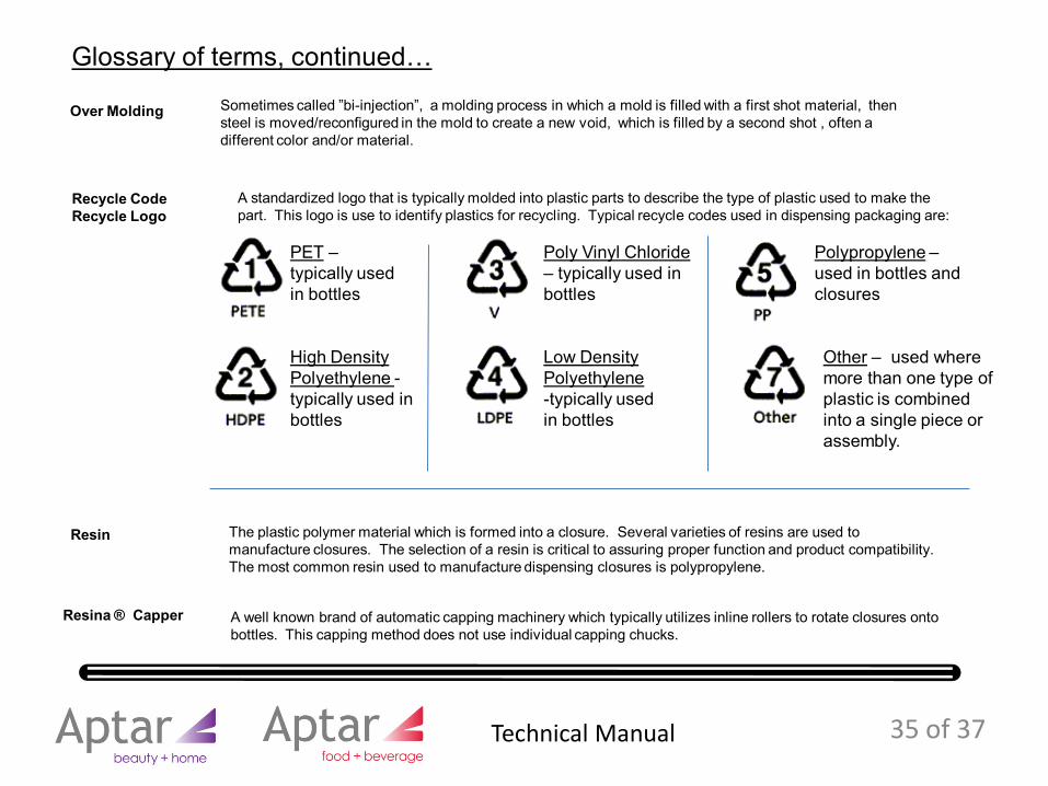
Recycle CodeRecycle Logo
A standardized logo that is typically molded into plastic parts to describe the type of plastic used to make the part. This logo is use to identify plastics for recycling. Typical recycle codes used in dispensing packaging are:
PET –typically used in bottles
High Density Polyethylene -typically used in bottles
Poly Vinyl Chloride – typically used in bottles
Low Density Polyethylene -typically used in bottles
Polypropylene –used in bottles and closures
Other – used where more than one type of plastic is combined into a single piece or assembly.
Resina ® Capper A well known brand of automatic capping machinery which typically utilizes inline rollers to rotate closures onto bottles. This capping method does not use individual capping chucks.
Technical Manual
Glossary of terms, continued…
36 of 37
Short A plastic part that has not been completely formed as a result of insufficient plastic material being injected into the mold. A shorted part (also known as a “short shot”) has an incomplete form, typically in the area furthest from the injection point. Often the shorted edges appear melted.
Sink A depressed area on a plastic part that is the result of plastic shrink in a thick section of a part. Sink is a normal result of shrink of thick sections, but can be minimized by reducing part thickness in the area.
Skirt The outermost wall of the body of a double wall closure which does not contain the closure thread. The skirt is used to provide an aesthetically pleasing interface between the closure and the container.
Spud The protrusion in the lid of a Snap Top® closure that fits into the dispensing orifice to seal the orifice when the lid is in the closed position.
Snap Top® A type of dispensing closure comprised of a body and a lid connected by a hinge. Typically the hinge is a biased hinge. Also known as a “Flip Top” closure.
Spout A raised protrusion on the deck of a Snap Top® closure which contains the orifice.
SPI The Society of the Plastics industry. The trade association representing the plastics manufacturing industry in the U.S. Members include the entire plastics supply chain. The SPI – Plastic Bottle Institute developed a set of plastic bottle thread standards which coordinate with closure standards to ensure closure-to-bottle compatibility.
S2 Dimension A bottle dimension that helps to define closure orientation. S2 is the distance from the land of the bottle to the underside of the thread at the bottle neck wall, within the first turn of thread, located at the position of orientation for the closure.
Technical Manual
Glossary of terms, continued…
Valve A molded Silicone membrane with integral slits that, when pressurized, allows product to flow. When the pressure is release, the valve closes and seals itself against flow.
37 of 37
Torque A turning or twisting force. Example: the twisting force needed to apply a threaded closure to a bottle. The units of measure are pounds force-inch (lbf-in) or newton-meters (N-m)
Viscosity The measurement of the resistance of a liquid to flow.Low viscosity = thin liquid = flows easilyHigh viscosity = thick liquid = resists flow
Viscosity is measured in “centipoise” (cP) using a rheometer, where water (at 20 C / 68 F) is the standard at 1 cP.Common product examples include:
Anti Freeze = approx. 15 cPMaple Syrup = approx. 1,600 cPShampoo = approx. 7,000 cPChocolate syrup = approx. 20,000 cPKetchup = approx. 60,000 cPtoothpaste = approx. 100,000 cPCaulking compound = approx. 7,000,000 cP
Surface Finish The degree of smoothness on plastic surfaces which comprise the closure. Typically closures have a “glossy”/shiny/ reflective surface or a “matte”/textured/non-reflective surface. Varying degrees of gloss and matte are possible in custom design closures.
Technical Manual