technical manual solenoid diaphragm pump 204...4,1 4,1 4,8 4,8 5,1 pump data permissible pressure p...
TRANSCRIPT

TECHNICAL MANUAL
TRANSLATION OF THE ORIGINAL TECHNICAL MANUAL EN
SOLENOID DIAPHRAGM PUMP 204.1

2 www.sera-web.com
INTRODUCTION
PUMP TYPE
R 204.1 - 1,2e C 204.1 - 1,2eR 204.1 - 2,4e C 204.1 - 2,4eR 204.1 - 7,0e C 204.1 - 7,0eR 204.1 - 10e C 204.1 - 10eR 204.1 - 35e C 204.1 - 35e
NOTE
Keep the operating manual for future use!
ATTENTION
Subject to technical modifications!
Quality notes
The sera quality management and quality assurance system is certified in accordance with DIN EN ISO 9001:2015.The sera product complies with the applicable safety requirements and accident prevention regulations.
NOTE
Record the exact type and serial number here ► can be read off the type plate on the pump.These data are important in the case of queries or for ordering spare and/or wear parts and must always be stated.
TYPE:
SERIAL NO:
www.sera-web.com 3
INTRODUCTION
These technical manual is divided into the following main parts:
TRANSPORT & STORAGE page 6
PRODUCT DESCRIPTION page 7
TECHNICAL DATA page 11
ASSEMBLY / INSTALLATION page 15
START-UP page 22
ELECTRICAL CONNECTIONS page 22
MAINTENANCE page 23
FFAULT ANALYSIS / CORRECTIVE ACTION page 26
SHUT-DOWN / DISPOSAL page 26
CLEARANCE CERTIFICATE page 29
Depending on the pump type (see order confirmation) the following additional instructions are included:
Control C204.1 TM10
Control R204.1 TM12
Control C204.1 PROFIBUS TM13
About this instructions
Special notes in these instructions are marked with text and danger symbols.
NOTE
Notes or instructions that faciliate work and ensure a safe operation.
ATTENTION
The non-observance of these safety instructions can result in malfunctions or material damages.
WARNING
The non-observance of these safety instructions can lead to material damages and personal injuries.
SI01 Note on the additional instructions „SAFETY INSTRUCTIONS“.

4 www.sera-web.com
www.sera-web.com 5
CONTENT
TRANSPORT & STORAGE ...........................................................................................................6General ................................................................................................................................................................... 6Storage ..................................................................................................................................................................... 6
PRODUCT DESCRIPTION ............................................................................................................7Type key ................................................................................................................................................................... 7Type plate ................................................................................................................................................................. 8Notes attached to the product ...................................................................................................................................... 8Materials .................................................................................................................................................................. 8Components of the pump ............................................................................................................................................ 9
TECHNICAL DATA ....................................................................................................................11NOISE MEASUREMENT ........................................................................................................................................... 13VISCOSITY, PUMPED MEDIUM .................................................................................................................................. 13TEMPERATURE DATA ................................................................................................................................................ 13AMBIENT CONDITIONS .......................................................................................................................................... 13Characteristics ......................................................................................................................................................... 13Dimensions .............................................................................................................................................................. 14
ASSEMBLY / INSTALLATION .....................................................................................................15
START-UP / ELECTRICAL CONNECTIONS ...................................................................................22
MAINTENANCE ......................................................................................................................23Overview of the tightening torques ............................................................................................................................. 23Changing the diaphragm .......................................................................................................................................... 23Spare and wear parts ............................................................................................................................................... 24
FFAULT ANALYSIS / CORRECTIVE ACTION ................................................................................26
SHUT-DOWN / DISPOSAL ........................................................................................................28Shut-down ............................................................................................................................................................... 28Disposal .................................................................................................................................................................. 28
CLEARANCE CERTIFICATE ........................................................................................................29

6 www.sera-web.com
General
sera products are checked for perfect condition and function previous to shipment.Check for transport damage immediately after arrival of goods. If damage is found, this is to be reported immediately to the responsible carrier and the manufacturer.
Storage
An undamaged packaging protects the unit during storage and should only be opened when the product is installed.Proper storage increases the service life of the product and includes prevention of negative influences such as heat, moisture, dust, chemicals etc.
The following storage specifications are to be obsered:
■ Storage place: cool, dry, dustfree and slightly ventilated ■ Storage temperature and relative air humidity see Chapter „TECHNICAL DATA“. ■ The maximum storage time for the standard packaging is 12 months.
If these values are exceeded, metal products should be sealed in foil and protected from condensation water with a suitable desiccant.
Do not store solvents, fuels, lubricants, chemicals, acids, disinfectants and similar in the storage room.
WARNING
Observe and follow the safety instructions by all means.See the additional instructions „SAFETY INSTRUCTIONS“.Man, machine and environment are endangered if the safety instructions are not observed.
SI01
TRANSPORT & STORAGE

www.sera-web.com 7
PRODUCT DESCRIPTION
Type key
Type of drive (combinations possible)C controllableM not adjustableR adjustableF Motor suitable for frequency converter operationi Frequency converter, mounted on the motorK Stroke mechanism with side drive shaft and connected to the drive via a clutchZ twin designX Stroke mechanism with two opposite pump heads, combined suction and pressure sideY Stroke mechanism with two opposite pump heads
Series204 (solenoid driven pumps)409 (motor driven pumps)410 (motor driven pumps)509 (motor driven pumps)
Revision index
max. Nominal capacity (litre/hour (each pump head))
Displacer (type of construction)e Single diap hragmML Multy-layer diaphragm
1 2 3 4 5
KM Piston daphragmK Piston
Type of control
6Pro+
C 204 . 1 - 1,2 e (example)
PRODUCT DESCRIPTION

8 www.sera-web.com
PRODUCT DESCRIPTION
Type plate
Each sera pump is factory provided with a type plate. The following information can be found on this type plate.
1
2
3
4
7
8
9
10
5 6
No. Designation
1 Pump type
2 Nominal flow rateDelivery volume of the pump at rated pressure with media similar to water.
3Minimum/maximum permissible pressure in the pump inletMinimum/maximum permissible pressure in the inlet cross section which the pump can be used for.Please consider that pressure depends on rotation speed, flow rate, temperature and static pressure at the inlet.
4Maximum permissible pressure in the pump outletMaximum permissible pressure in the outlet cross section which the pump can be used for. Please consider that pressure depends on rotation speed, flow rate, temperature and static pressure at the outlet.
5 Nominal stroke frequency
6 Rated frequency
7 Serial number of the pump
8 Max. power consumption
9 Max. operating voltage
10 Max. current consumption
Notes attached to the product
Symbols which are directly attached to the pump, e.g. arrows for direction of rotation or symbols for fluid connectionsare to be observed and kept in legible condition.
Materials
The materials used are stated in the order confirmation and the product description..
www.sera-web.com 9
PRODUCT DESCRIPTION
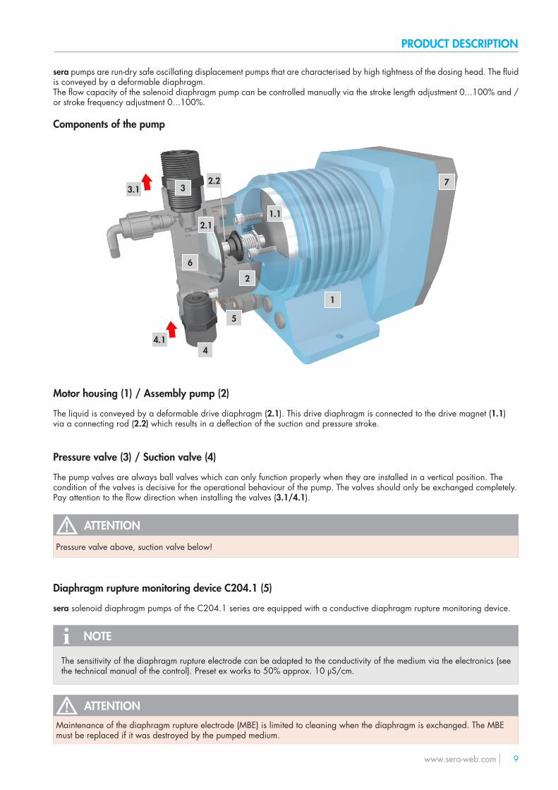
sera pumps are run-dry safe oscillating displacement pumps that are characterised by high tightness of the dosing head. The fluid is conveyed by a deformable diaphragm.The flow capacity of the solenoid diaphragm pump can be controlled manually via the stroke length adjustment 0...100% and /or stroke frequency adjustment 0...100%.
Components of the pump
Motor housing (1) / Assembly pump (2)
The liquid is conveyed by a deformable drive diaphragm (2.1). This drive diaphragm is connected to the drive magnet (1.1) via a connecting rod (2.2) which results in a deflection of the suction and pressure stroke.
Pressure valve (3) / Suction valve (4)
The pump valves are always ball valves which can only function properly when they are installed in a vertical position. Thecondition of the valves is decisive for the operational behaviour of the pump. The valves should only be exchanged completely.Pay attention to the flow direction when installing the valves (3.1/4.1).
ATTENTION
Pressure valve above, suction valve below!
Diaphragm rupture monitoring device C204.1 (5)
sera solenoid diaphragm pumps of the C204.1 series are equipped with a conductive diaphragm rupture monitoring device.
NOTE
The sensitivity of the diaphragm rupture electrode can be adapted to the conductivity of the medium via the electronics (see the technical manual of the control). Preset ex works to 50% approx. 10 μS/cm.
ATTENTIONMaintenance of the diaphragm rupture electrode (MBE) is limited to cleaning when the diaphragm is exchanged. The MBE must be replaced if it was destroyed by the pumped medium.
1
2
6
3
4
3.1
4.1
2.1
2.2
1.1
5
7

10 www.sera-web.com
PRODUCT DESCRIPTION
Pump body (6)
Depending on the applied backpressure, movements of the plastic pump body in elastic materials are possible.This does not affect the pumps’s service life or operational reliability.
Manual vent valve (only FRP-execution C 204.1-1,2e - ... -10e)
The vent valve is used to release the manual pressure in thepump body (4) during commissioning. Open vent valve whenpump primes first time.When vent valve is opened gas including medium escapes intothe feedback line. The vent valve must be closed again as soonas only medium without gas constituent escapes. The pumpnow feeds the medium into the pressure line.Open again for another ventilation. The vent valve consists of avent screw (6.1) with integrated hose nozzle (6.2), which must befitted with a hose (6.3) (inside diameter 6 mm) as feedback line.The leaking medium incl. the gas admixtures must be disposedoff properly.The vent screw is inserted during normal operation
ATTENTIONOpen vent screw with great caution and perform max. 1 turn. Take care that the tightness of the thread is still guaranteed.
ATTENTIONThe vent screw must always be closed during the driving pro-cess.
6.2
6.1
6.3
Control (7)
NOTE
See the technical manual of the control!
R204.1
The electronics enable, among others, the proportional dosing via analog signals 4 … 20mA.The three LEDs serve for indicating warning signals, errors and the current status of the dosing pump.An indicator “empty” along with pre-alarm and dry run indicators is installed as standard.
C204.1
The electronics permit proportional volumetric dosing via analogue signals 0/4 ... 20 mA or contact signals with the option ofdividing or duplicating the pulse.An integrated LCD display and three LED’s for warning and fault display indicate the current status of the dosing pump.A connection for flow monitoring or flow measurement as well as an empty signal with pre-alarm and dry operation alarm areinstalled as standard.

www.sera-web.com 11
TECHNICAL DATA
PUMP DATA
Permissible pressure p2max.at the pump outlet bar
Nominal capacity QNat p2max.
l/h 50/60 Hz
Quantity per stroke ml/stroke (100%)
Max. suction height mWC
Min./max. permissible pressure at the pump inlet bar p1min/max
Recommended nominal diameter DN of the connecting pipes mm
Nominal stroke frequency 1/min 50/60 Hz
Weight approx. kg
C 204.1-...
1,2e 2,4e 7,0e 10e 35e
10 10 10 6 1,5
0-1,2 0-2,4 0-7 0-10 0-35
0,13 0,27 0,78 1,11 3,89
2 2 3 3 3
-0,2/0 -0,2/0 -0,3/0 -0,3/0 -0,3/0
5 5 5 5 10
150 150 150 150 150
4,1 4,1 4,8 4,8 5,1
R 204.1-...
1,2e 2,4e 7,0e 10e 35e
10 10 10 6 1,5
0-1,2 0-2,4 0-7 0-10 0-35
0,13 0,27 0,78 1,11 3,89
2 2 3 3 3
-0,2/0 -0,2/0 -0,3/0 -0,3/0 -0,3/0
5 5 5 5 10
150 150 150 150 150
4,1 4,1 4,8 4,8 5,1
PUMP DATA
Permissible pressure p2max.at the pump outlet bar
Nominal capacity QNat p2max.
l/h 50/60 Hz
Quantity per stroke ml/stroke (100%)
Max. suction height mWC
Min./max. permissible pressure at the pump inlet bar p1min/max
Recommended nominal diameter DN of the connecting pipes mm
Nominal stroke frequency 1/min 50/60 Hz
Weight approx. kg

12 www.sera-web.com
TECHNICAL DATA
ELECTRICAL DATA
Middle power draw W
Nominal voltage V
Frequency Hz
Inlet voltage, control input V DC
Minimum contact signal time ms
Analogue input resistance Ω
Current Consumption during stroke A (at 230V)
Recommended fuse (circuit breaker)
Insulation class ISO
Enclosure IP
R 204.1-...e
20
100 - 240
50/60
5...30
55
100
max. 1,0
C2A
F
65
ELECTRICAL DATA
Middle power draw W
Nominal voltage V
Frequency Hz
Inlet voltage, control input V DC
Minimum contact signal time ms
Analogue input resistance Ω
Current Consumption during stroke A (at 230V)
Digital outputinternal/external supply
Recommended fuse (circuit breaker)
Insulation class ISO
Enclosure IP
C 204.1-...e
33
100 - 240
50/60
5...30
55
100
max. 1,0
PNPmax. 15V DC, 50mA / max. 30V DC, 350mA
C2A
F
65
www.sera-web.com 13
TECHNICAL DATA
60 °C
10 °C
40 °C
0 °C
40 °C
0 °C
1000 m
< 90%
AMBIENT CONDITIONS
Max. installation altitude above sea level
Max. relative air humidity
TEMPERATURE DATA
Max. liquid temperature
Min. liquid temperature
Max. operating temperature
Min. operating temperature
Max. storage temperature
Min. storage temperature
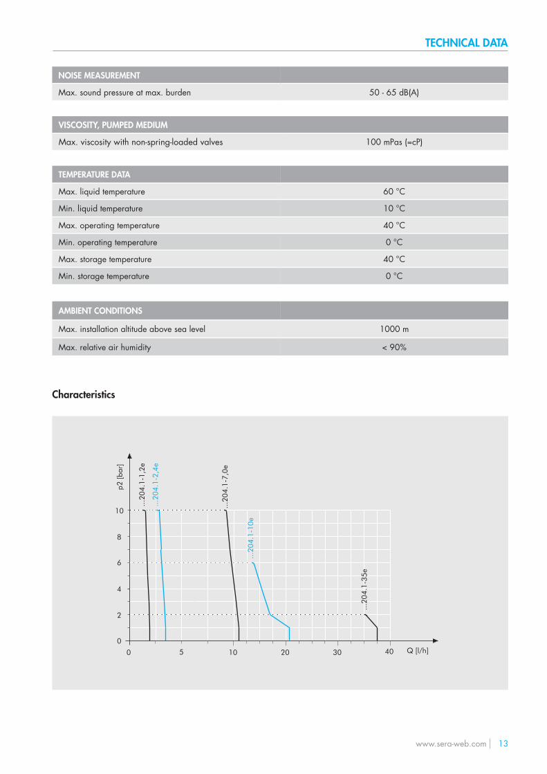
100 mPas (=cP)
NOISE MEASUREMENT
Max. sound pressure at max. burden 50 - 65 dB(A)
VISCOSITY, PUMPED MEDIUM
Max. viscosity with non-spring-loaded valves
0
2
4
6
8
10
0 10 20 30 40
...20
4.1-
2,4e
...20
4.1-
1,2e
...20
4.1-
10e
...20
4.1-
7,0e
...20
4.1-
35e
5 Q [l/h]
p2 [b
ar]
Characteristics

14 www.sera-web.com
TECHNICAL DATA
Dimensions
6,5Ø
~ L
~ H
~ B
SD
G
SUCTION VALVES
DN Nominal width
G Connection thread
S PP-FRP / PVDF-FRP
S PVC-U
S 1.4571
PRESSURE VALVES
DN Nominal width
G Connection thread
D PP-FRP / PVDF-FRP
D PVC-U
D 1.4571
MAX. TOTAL HEIGHT
H
MAX. TOTAL WIDTH
B
MAX. TOTAL LENGTH
L
L (with vent valve)
(Measurements in mm)
...204.1-...
...-1,2e ...-2,4e ...-7,0e ...-10e ...-35e
5 5 5 5 10
G¾ G¾ G¾ G¾ G¾
80 80 80 80 75
70 70 70 70 80
70 70 70 70 76
5 5 5 5 10
G¾ G¾ G¾ G¾ G¾
80 80 80 80 75
70 70 70 70 80
70 70 70 70 76
175 175 175 175 175
130 130 130 130 130
275 275 275 275 275
305 305 305 305 ---

www.sera-web.com 15
ASSEMBLY / INSTALLATION
NOTE
Pump design data for dosing and its temperature can be found in the order confirmation.
NOTE
Operating conditions:Ambient temperature, relative air humidity and max. installation altitude ► see chapter „Technical data“.
■ The standard model of the pump is only approved for installation in dry areas in a non-aggressive atmosphere. ■ Protect the pump from heat sources, direct sunlight and UV light. ■ See “Dimensions” chapter for dimensions of the pump connections and fixing holes. ■ Fixing the pump with at least four bolts above the pump base is required for safe operation. ■ Install the pump so that there is no vibration and no tension and that it is aligned precisely. ■ Install the pump at the optimum possible operating height. Mount the pump so that the valves are vertical. ■ Ensure that there is sufficient space around the pump body and the suction and pressure valve so that these parts can be
easily dismantled if required. ■ Design the nominal diameters of the downstream piping and the valves installed in the system to be the same size or larger
than the nominal inlet and outlet diameters of the pump. ■ To check the pressure ratios in the piping system, it is recommended to provide connections for pressure measurement
fittings (e.g. manometers) near the suction and pressure ports. ■ Drain valves must be provided. ■ Before connecting the pipes, remove the plastic caps on the suction and pressure ports of the pump. ■ Check the fastening bolts for the pump body for tightness and tighten if necessary, see chapter “Overview of the tightening
torques”. ■ Connect pipes to the pump so that there are no forces acting on the pump, such as e.g. misalignment, weight or strain of
the pipe. ■ Keep the suction pipes as short as possible. ■ Use pressure and medium resistant hoses / pipes. ■ All pipes and containers connected to the pump must comply with the regulations and must be cleaned, tension-free and
intact. ■ Display devices must be easily accessible and readable.
In order to avoid cavitation, overload or excessive delivery, the following points should be noted:
■ Avoid high suction heights. ■ Keep pipes as short as possible. ■ Select sufficiently large nominal diameters. ■ Avoid unnecessary choke points. ■ Install a pulsation damper. ■ Install overpressure protection. ■ Install a pressure-sustaining valve, if necessary ■ Provide feed line for outgassing media.
WARNING
The pump with a control is only designed for operation outside Ex-zonest!
WARNING
Observe and follow the safety instructions by all means.See the additional instructions „SAFETY INSTRUCTIONS“.Man, machine and environment are endangered if the safety instructions are not observed.
SI01

16 www.sera-web.com
ASSEMBLY / INSTALLATION
1
1.2
1.4
2
SUCTION SIDE (1)
The following fittings can be used on the suction side:
1.1 Line strainer 1.2 Suction aidSiphon vessel
1.3 Suction lance 1.4 Multifunction device
1.5 Foot valve 1.6 Shut-off valve
1.3
2
1

www.sera-web.com 17
ASSEMBLY / INSTALLATION
1
2.6
PRESSURE SIDE (2)
The following fittings can be used on the pressure side:
2.1 Vent valve 2.2 Injection fitting
2.3 Dosing valve 2.4 Pulsation damper
2.5 Diaphragm pressure keeping valve 2.6 Diaphragm relief valve
2.7 Multifunction valve 2.8 Flow meter
2.9 Flow monitor 2.10 Shut-off valve
1

18 www.sera-web.com
ASSEMBLY / INSTALLATION
SUCTION SIDE (1)
Line strainer (1.1)
Connect suction line slightly above the bottom of the tank and install a line strainer (0.1 – 0.5 mm mesh size – dependingon valve nominal diameter of the pump).
ATTENTION
If impurities are not removed, this results in malfunctions of the pump and the system.
Suction aid / siphon vessel (1.2)
For high tanks without connection on the bottom of the tank ► install suction aid / siphon vessel.Thereby, pay attention to accelerating pressures which may be generated in a long suction pipe.
Suction lance (1.3)
Install a suction lance for removal of chemicals from tanks and barrels.The integrated foot valve prevents the backflow of the suctioned medium.The suction lances are equipped with a level switch for „empty“ signal.
Multifunction device (1.4)
The multifunction device is installed in the suction side piping of the pump and is used for determination of the deliveryrate of pumps under real operating conditions.The device can be filled either using a pending tank volume (communicating container) or using a hand vacuum pump.
Foot valve (1.5)
To prevent running dry of the suction line ► install foot valve (check valve) at the end of the suction line.

www.sera-web.com 19
ASSEMBLY / INSTALLATION
PRESSURE SIDE (2)
Vent valve (2.1)
If air can be drawn in due to falling liquid level in the suction tank and at the same time delivered to a pressurised line or against a pressure-sustaining valve ► install vent valve in the pressure line.
NOTE
The delivery flow can be interrupted if there is air in the suction line!
Injection fitting (2.2)
Install an injection fitting that routes into a main line to prevent the backflow of the pumped medium in the dosing line.
WARNING
Unwanted mixing in the dosing line occurs if any possible backflow from the main line is not prevented.
Dosing valve (2.3)
Installation of the dosing valve prevents the liquid from the system to be treated being able to penetrate into the dosing line.
Pulsation damper (2.4)
Damping of the pulsation by installation of pulsation dampers if:
■ a low-pulsation delivery flow is desired for process reasons, ■ acceleration forces caused by the piping geometry must be removed.
Install pulsation damper as close as possible to the pump head.If both pulsation damper and pressure-sustaining valve should be integrated, install the pressure-sustaining valvebetween pump and pulsation damper.
WARNING
Undamped acceleration forces can result in the following faults / damage:
■ flow rate fluctuations ■ dosing errors ■ pressure surges ■ valve shocks ■ increased wear on the suction and pressure sides of the pump ■ mechanical destruction of the pump ■ leaks and valve shocks if the permissible maximum pressure on the pump pressure ■ side is exceeded ■ damage to the piping and its installed fittings

20 www.sera-web.com
ASSEMBLY / INSTALLATION
Diaphragm pressure-keeping valve (2.5)
If dosing into a main line with negative pressure ► install pressure-keeping valve in the dosing line.
ATTENTION
It must be ensured during the installation that excess delivery (due to positive pressure difference (≥ > 1 bar) between pres-sure and suction sides) is avoided.
Diaphragm relief valve (2.6)
If the permissible pressure in the system can be exceeded by closing any shut-off valve or by clogging of the line ► install dia-phragm relief valve.
When using an external overflow valve, the following is applicable for the return line:
■ Route the return line sloping downward into the storage tank which is under atmospheric pressure or into an open drainage channel.
■ Or connect directly to the pump suction line, but only if there is no check valve in the suction line (e.g. foot valve of a sucti-on lance).
ATTENTION
Shut-off valves must not be closed when the pump is running!
WARNING
An overpressure protection device (e.g. relief valve) must generally be provided if the permissible operating pressure can be exceeded.
ATTENTION
If the permissible operating pressure is exceeded and the pump is not equipped with overpressure protection, the pump will be damaged.
WARNING
The pumped medium can spray out if the pump is damaged.
Multifunction valve (2.7)
The multifunction valve provides the following functions:
■ pressure-keeping valve function, ■ overflow valve function, ■ pressure relief function, ■ venting.
The multifunction valve is mounted directly on the pump pressure port.

www.sera-web.com 21
ASSEMBLY / INSTALLATION
Flow meter (2.8)
For measurement and monitoring of the flow rate ► install flow meter.The application range is restricted to media that are similar to water.The flow meter is screwed upright on the pressure port of the pump and connected to the pump electronics via the input for flow monitoring.
Flow monitor (2.9)
To record the flow rate of the pump ► install flow monitor.The application range is restricted to media that are similar to water.The flow monitor is screwed upright on the suction port of the pump and connected to the pump electronics via the input for flow monitoring.

22 www.sera-web.com
Adequate fastening at the pump foot and compliance with the operating parameters specified in the technical data arerequired for the operation of the pump.
Checks before every start-up:
■ Check all connections for tightness. ■ Tighten fixing bolts of the pump body with the specified tightening torques
(see „Overview of the tightening torques“ chapter). ■ Check of the electrical connections. ■ Check of the mains voltage on the rating plate with the local conditions.
WARNING
Observe and follow the safety instructions by all means.See the additional instructions „SAFETY INSTRUCTIONS“.Man, machine and environment are endangered if the safety instructions are not observed.
SI01
Electrical connections
Start-up
START-UP / ELECTRICAL CONNECTIONS
WARNING
Observe and follow the safety instructions by all means.See the additional instructions „SAFETY INSTRUCTIONS“.Man, machine and environment are endangered if the safety instructions are not observed.
SI01
NOTE
Operating voltage range see chapter „TECHNICAL DATA“.
NOTE
The pump restarts in the selected operating mode with the specified parameters after switching on again or after restoration of the power supply following a power failure.
ATTENTION
The pump restarts in the selected operating mode with the specified parameters after switching on again or after restoration of the power supply following a power failure.
www.sera-web.com 23
MAINTENANCE
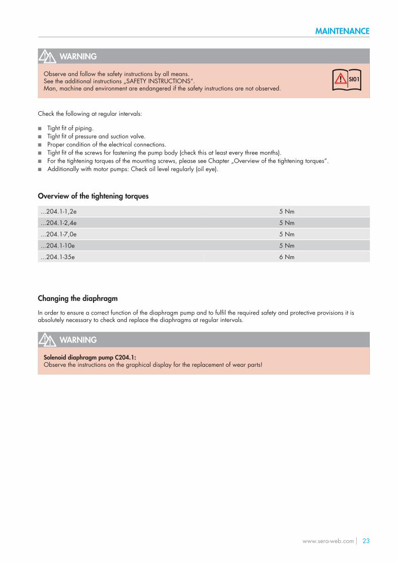
Check the following at regular intervals:
■ Tight fit of piping. ■ Tight fit of pressure and suction valve. ■ Proper condition of the electrical connections. ■ Tight fit of the screws for fastening the pump body (check this at least every three months). ■ For the tightening torques of the mounting screws, please see Chapter „Overview of the tightening torques“. ■ Additionally with motor pumps: Check oil level regularly (oil eye).
WARNING
Observe and follow the safety instructions by all means.See the additional instructions „SAFETY INSTRUCTIONS“.Man, machine and environment are endangered if the safety instructions are not observed.
SI01
Overview of the tightening torques
...204.1-1,2e 5 Nm
...204.1-2,4e 5 Nm
...204.1-7,0e 5 Nm
...204.1-10e 5 Nm
...204.1-35e 6 Nm
Changing the diaphragm
In order to ensure a correct function of the diaphragm pump and to fulfil the required safety and protective provisions it isabsolutely necessary to check and replace the diaphragms at regular intervals.
WARNING
Solenoid diaphragm pump C204.1:Observe the instructions on the graphical display for the replacement of wear parts!

24 www.sera-web.com
MAINTENANCE
Replacement of the working diaphragm:
■ Loosen suction and pressure lines of pump. ■ Make a note of the current setting of the stroke length. ■ Set stroke length to 0 %. ■ Screw out fixing screws (1) of pump body (2) (take off with disks (3)). ■ Remove pump body (with valves) to the front. ■ Unscrew working diaphragm (4) from connecting rod (5). ■ Screw new working diaphragm onto connecting rod. ■ Set stroke length to 50 %. ■ Put pump body onto base ring (6). Tighten fixing screws crosswise with correct torque (see Chapter „Overview of the tigh-
tening torques“).
1
2
3
4
5
6
ATTENTION
When mounting the pump body please note:Pressure valve above; suction valve below (Consider the direction of the arrows on the valves)!
■ Fix suction and pressure line. ■ Reset original stroke length. ■ Apply voltage. ■ The solenoid diaphragm pump is ready for operation
Spare and wear parts
The following parts are considered as wear parts of the dosing pump:
■ Diaphragm (Diaphragm kit) ■ Insert (Diaphragm kit) ■ Diaphragm rupture electrode ►C204.1 ■ Valves kit (included o-ring kit) ■ O-ring kit
Depending on their use and period of use, wear parts must be replaced at regular intervals in order to ensure reliablefunctioning of the dosing pump.
sera recommends replacement of wear parts after 3000 operating hours or at least once per year.
In the event of premature diaphragm rupture caused by harsh operating conditions, switch off the dosing pump andreplace the drive diaphragm (in accordance with „Diaphragm replacement“ chapter).
The following parts are considered as spare parts of the dosing pump:
■ Pump body kit (included mounting kit) ■ Mounting kit

www.sera-web.com 25
MAINTENANCE
Pos. Kit Materials consisting ofX010 Valves PVC-U; PP-FRP; PVDF-FRP Suction valve
Pressure valveO-ring kit
X011 Suction valve 1.4571 Suction valveO-ring kit
X012 Pressure valve 1.4571 Pressure valveO-ring kit
X020 Pump body Pump bodyMounting kit
X030 Mounting Screws, completeX040 Diaphragm Drive diaphragm
InsertX050 Diaphragm rupture electrode Diaphragm rupture electrode ► C204.1X070 O-rings
PVC-U
PP-, PVDF-FRP(204.1-35e)
1.4571
X020
X010
X012
X010
X011
X070
X020
X020
X020
X030
X030
X030
X030
X040
X070
PP-, PVDF-FRP
X050

26 www.sera-web.com
FAULT ANALYSIS / CORRECTIVE ACTION
sera products are sophisticated technical products which are only shipped after having been thoroughly tested and checked at our factory.Should there be any faults, these can be detected and rectified easily and quickly based the instructions in the tables.
NOTE
Analysis of the error messages in the display for the pumps with a control ► see the operation instructions of the control!
Fault type Possible cause Corrective action
Cor
rect
ive
actio
n!
Disp
lay,
LED
not
lit!
► P
ump
with
con
trol
Mot
or d
oes
not s
tart!
► d
iaph
ragm
pum
p
Dam
age
to s
troke
mec
hani
sm /
driv
e!
Pum
p do
es n
ot d
raw
in!
Pum
p do
es n
ot d
eliv
er!
Flow
rate
is n
ot re
ache
d!
Del
iver
y he
ad is
not
reac
hed!
Flow
rate
fluc
tuat
es!
Max
imum
per
miss
ible
flow
rate
exc
eede
d!
Pipe
osc
illat
es h
eavi
ly!
Too
high
noi
se d
evel
opm
ent!
Serv
ice
life
of th
e dr
ive
diap
hrag
m to
o lo
w!
Driv
e is
over
load
ed (p
erio
dica
lly o
ccur
ring
noise
s)!
Leak
age
on p
ump
head
!
█ █ █ Suction height too high. Reduce suction height or suction resistance.
█ █ █ █ Suction pipe leaking. Check seals, tighten pipe connections.
█ █ █ █ █ Shut-off valves in pipingclosed.
Open shut-off valves or check opening state ► check pump for possible damage.
█ █ █ No pumped medium in stora-ge tank. Fill storage tank.
█ █ █ █ █ Pump valves leaking. Remove and clean valves.
█ █ █ █ Pump valves (ball seats)damaged.
Remove and clean valves, checkfunction; replace valves if necessary.
█ █ Pump valves incorrectly moun-ted or valve balls missing.
Check installation position and completeness ► replace missing parts or install correctly.
█ █ █ █ Filter in suction line clogged. Clean filter.
█ █ █ █ █ █ Electrical data of the pump donot match mains data.
Check order data.Check electrical installation.Adjust motor to the network onsite (for diaphragm pumps).
█ █ █ █ █ █ █ █ Backpressure too high.Measure pressure with manometer directly above pressure valve if possible and compare with permissible backpressure.
█ █ █ █ █ Foreign matter in the pumpvalves. Remove and clean valves.
█ █Pressure on suction side higher than at the end of the pressure pipe.
Check geodetic conditions, install float valve or pressure keeping valve if necessary.
█ █ █ █ █ █ █ █ Acceleration height too highdue to pipe geometry.
Check acceleration height on suction and pressure sides with manometer and compare with design data ► install a pulsation damper if necessary.
█ █Materials coming into contactwith the medium not suitable for the pumped medium.
Check whether the pumped medium matches the design data and select other materials if necessary.

www.sera-web.com 27
CORRECTIVE ACTION / FAULT ANALYSIS
Fault type Possible cause Corrective action
Pum
pe lä
uft n
icht
!
Disp
lay,
LED
dun
kel!
► P
umpe
mit
Steu
erun
g
Ant
riebs
mot
or lä
uft n
icht
an!
► M
otor
pum
pe
Schä
den
in H
ubge
trieb
e /
Ant
rieb!
Pum
pe s
augt
nic
ht a
n!
Pum
pe fö
rder
t nic
ht!
Förd
erstr
om w
ird n
icht
erre
icht
!
Förd
erhö
he w
ird n
icht
erre
icht
!
Förd
erstr
om is
t sch
wan
kend
!
Förd
erstr
om g
röße
r als
zulä
ssig
!
Rohr
leitu
ng s
chw
ingt
seh
r sta
rk!
Ger
äusc
hent
wic
klun
g zu
hoc
h!
Lebe
nsda
uer d
. Ant
riebs
mem
bran
e zu
ger
ing!
Ant
rieb
ist ü
berla
stet (
perio
disc
h au
ftret
ende
Ger
äusc
he)!
Leck
agen
am
Pum
penk
opf!
█ █ █ █ Viscosity of the pumped medi-um too high.
Check viscosity of the pumped medium and compare with design data ► reduce concen-tration or increase temperature if necessary.
█ █ █Pumped medium is outgassingin the suction pipe and/orthe pump body.
Check geodetic conditions and compare with data of the pumped medium. Operate pump with suction side supply, reduce temperatureof the pumped medium.
█Air in suction line while pres-sure is present on the pressureside.
Vent pressure side.
█ Power supply failed / swit-ched off. Restore power supply.
█ █ █ █ █ Pipe connections leaking. Tighten connections according to type of mate-rial. Be careful with plastic ► risk of fracture!!
█ █ Pumped medium frozen inpipe.
PRemove pump and check for possible damage - increase temperature of the pumped medium.
█ █ █ No mains power connection. Connect mains power supply.
█ Pump valves dry. Moisten pump body and valves.Open vent valve.
█ █ █ █ Temperature too low. Check flowability of the dosing medium. Tem-perature of the medium see „Technical data“.
█ █ █ █ █ █ █ Diaphragm rupture.Replace the diaphragm according to the descriptions in Chapter „Replacing the dia-phragm“.
█ Reversible thermal fuse of thepump has tripped.
Let temperature of the pump cool down.Check ambient temperature.
█ Fuse in electronics blown. ► Pump with control Return pump for repair.
█ █ █ █Compensating valve not adju-sted to operating conditions. ► diaphragm pump KM
Set compensating valve according to opera-ting conditions. ► diaphragm pump KM
█ Home position misadjusted ► 204.1 Reset stroke length ► 204.1

28 www.sera-web.com
SHUT-DOWN / DISPOSAL
Shut-down
■ Switch off piston diaphragm pump. ■ Rinse pump head and remove pumped medium; make sure that the rinsing agent is suitable for pumped medium and pump
head.
Disposal
■ Shut-down system. Please see “Shut-down“.
Dismantling and transport
■ Shut-down system. Please see “Shut-down“. ■ Remove all fluid residues from pump body, clean thoroughly, neutralize and decontaminate. ■ Package unit and ship.
NOTE
A clearance certificate must be filled in when systems are returned to the manufacturer.Acceptance will be rejected if this clearance certificate is not attached.
Complete disposal
■ Remove all fluid residues from unit. ■ Drain off lubricants and dispose of according to regulations! ■ Dismount materials and send them to a suitable waste disposal company!
WARNING
Observe and follow the safety instructions by all means.See the additional instructions „SAFETY INSTRUCTIONS“.Man, machine and environment are endangered if the safety instructions are not observed.
SI01

www.sera-web.com 29
NOTE
Inspection / repair of machines and machine parts is only carried out after the opposite clearance certificate was filled in correctly and completely by authorized and qualified personnel.
NOTE
Acceptance will be refused if parts are returned to the manufacturer without a proper clearance certificate.
All industrial companies are obligated by the legal provisions for occupational health, e.g. the workplaces ordinances, the Ordi-nance on Hazardous Substances, the regulations for prevention of accidents and the environmental protection regulations such as the Waste Management Act and the German Household Water Act to protect their employees or man and the environment from detrimental effects when handling hazardous substances.
Should special safety precautions be necessary despite careful draining and cleaning of the product the necessary information are to be provided.
Machines which are operated with radioactive media shall only be inspected and/or repaired in the safety area of the owner by a sera specialized fitter.
The clearance certificate is part of the inspection-/repair order. sera reserves the right to refuse acceptance of the order for other reasons.
NOTE
Please make a copy and leave the original with the operating instructions!(can also be downloaded from: www.sera-web.com)
CLEARANCE CERTIFICATE

30 www.sera-web.com

www.sera-web.com 31 1
Clearance Certificate
www.sera-web.com
QSF
469
-01
en /
11.2
014
/ PM
□
ProductType Serial-No.
the product was carefully emptied before shipping / delivery, and cleaned inside and outside. □ YES
Conveying mediumDesignation Concentration %
Properties
Please tick!
If either of the listed properties, then enclose the appropriate safety and handling instruc-tions.
The product was used with health or water-polluting substances and came up with labeling requirements and pollution prone media in contact.
□ YES
□ NO
Special security arrangements with respect to health or water-hazardous mediaare in the further handling
□ not required
□ required
The following safety precautions regarding rinsing, residual liquids and waste disposal are required:
Process dataThe product was used with the following operating conditions described conveying medium:
Temperature °C Pressure bar
Sender
Company: Telephone:
Contact person: FAX:
Address: E-mail:
Zip code, City: Your order No:
We confirm that we have the information in this safety certificate (Clearance Certificate) have been correctly and completely and that the returned parts were carefully cleaned. The parts are sent free of residues of dangerous amount.
Place, Date Department Signature(and company stamp)
□Corrosive
□Flammable
□Oxidising
□Unhealthy
□Toxic
□Harmless
□Dangerous for
the environment
□Bio-
hazardous
□Radioactive
□Explosive
□Irritant

TM11
-01
EN
190
109
sera
® is
a re
giste
red
trade
mar
k of
ser
a G
mbH
. Te
chni
cal d
etai
ls su
bjec
t to
chan
ge. s
era
shal
l not
acc
ept a
ny li
abili
ty fo
r erro
rs o
r om
issio
ns o
r for
prin
ting
erro
rs.
FOLLOW US
sera ProDos GmbHsera-Str. 134376 ImmenhausenGermanyTel. +49 5673 999 02Fax +49 5673 999 [email protected]