technical manual - stryker corporation...portage, mi 49002 usa e-mail:...
TRANSCRIPT

Technical Manual
Version: INT/R921-PM/1-05/18

This page intentionally left blank!

Technical Manual - Contents 3 of 18
Contents
1 General information..................................................................................................................... 4
1.1 About this manual.................................................................................................................. 4
1.2 Indications for use..................................................................................................................4
1.3 Contact................................................................................................................................... 4
1.4 FAQ and training.................................................................................................................... 4
1.5 Warranty................................................................................................................................. 5
1.6 Authorization of personnel..................................................................................................... 5
1.7 Warning, caution and note.....................................................................................................5
1.8 Disclaimer............................................................................................................................... 5
2 Maintenance..................................................................................................................................6
2.1 Software maintenance tool.....................................................................................................6
2.2 Annual maintenance...............................................................................................................7
2.3 After-service test.................................................................................................................... 7
2.3.1 Electrical safety test....................................................................................................... 8
2.3.2 Control panel test...........................................................................................................8
2.3.3 Setpoint temperature test...............................................................................................8
2.3.4 Overtemperature alarm test........................................................................................... 9
2.4 Corrective maintenance..........................................................................................................9
2.4.1 Replacing the fuses........................................................................................................9
2.4.2 Replacing front cover MA1200.....................................................................................11
3 Troubleshooting......................................................................................................................... 14
4 Appendices................................................................................................................................. 16
4.1 After-service test and preventive maintenance form............................................................16

Technical Manual - General information 4 of 18
1 General information
1.1 About this manual
In this manual, you can find important information about how to operate the Mistral-Air® Warming
Unit - SYK (MA1200-PM) (hereafter referred to as ‘the device’).
The manual helps you with the operation and the maintenance of the device, in a safe and
responsible manner.
Read this manual carefully. Complete all the procedures. Do the procedures in the given sequence.
Always keep the manual near the device.
1.2 Indications for use
The Mistral-Air® Warming System is a forced air warming device and comprises of a warming
unit and a variety of blankets. It is intended to raise and maintain patient temperature by means of
surface warming.
1.3 Contact
Stryker Medical
3800 E. Centre Avenue
Portage, MI 49002
USA
E-mail: [email protected]
Website: www.stryker.com
1.4 FAQ and training
Please refer to our website (www.the37company.com) for an up-to-date overview of the frequently
asked questions of the Mistral-Air® products: home / mistral-air | frequently asked questions.
If requested, The 37Company will provide any additional information which is required to repair the
parts designated as repairable.
Warning!
The device may only be operated by trained clinicians and maintenance may only be
performed by trained biomedical technicians or engineers. Both user groups must be
trained by certified trainers from Stryker.

Technical Manual - General information 5 of 18
1.5 Warranty
For the warranty provisions, ask your local Stryker representative.
1.6 Authorization of personnel
Make sure that only authorized personnel use the device.
1.7 Warning, caution and note
Warning!
A "warning" tells you that there is a risk of personal injury or death.
Caution!
A "caution" tells you that:
• there is a risk of damage to the device, and/or
• there is a risk of damage to other equipment.
A "note" gives more information.
1.8 Disclaimer
The manufacturer reserves all rights. No part of this document may be reproduced or published,
electronically, mechanically, in print, photographic print, on microfilm or by any other means
whatsoever, without the explicit consent of The 37Company.
The content of this document has been compiled with the greatest possible care and this
information can be regarded as reliable. Nevertheless, the manufacturer reserves the right to
make alterations and improvements to the device. These may not yet have been described in the
instructions. The manufacturer cannot be held liable for the final outcome of the patients’ treatment.
This document contains proprietary information that may not be disclosed to third parties. This
document may not be used without the explicit written consent of the manufacturer.
These instructions are intended for personnel authorized to work with and/or service the medical
device described in this manual.

Technical Manual - Maintenance 6 of 18
2 Maintenance
Warning!
• Maintenance may only be performed by trained biomedical technicians or engineers.
Both user groups must be trained by certified trainers from Stryker.
• Preventive maintenance needs to be performed on an annual basis.
Caution!
Clinical users may not repair or open the device in the event of a malfunction. This can
damage the appliance and will invalidate the warranty.
Have the device serial number ready when you contact the hospital service department or the local
supplier for technical support. The serial number is located on the label on the back of the device.
Before performing maintenance, consult the device insulation diagram below.
2.1 Software maintenance tool
A special software maintenance tool (MA1200 Programmer) can be provided by your local Stryker
representative. This password protected tool can be set up on any PC operating on Windows 7, 8,
or 10. This PC then needs to be connected to the data port protected by the cord anchor plate at
the back of the housing (see Connecting the power supply cord in the user manual for information
on how to remove the cord anchor plate) by an RS232 cable (and a USB converter).

Technical Manual - Maintenance 7 of 18
MA1200 Programmer can be used to reset the filter timer, adjust the setpoints to compensate for
increased heat loss when using a 3 metre long hose, update the firmware and perform the after-
service test protocol tests (see After-service test on page 7).
A work instruction (TSCI-W-92) for the software maintenance tool is available for download at the
business partner menu of the 37Company website.
2.2 Annual maintenance
Preventive maintenance needs to be performed on an annual basis.
At every service interval, please follow these steps:
1. Clean the device (see Cleaning).
2. Check if the filter is polluted. If so, replace the filter (see Replacing the filter (MA1200-1001-PM)).
3. Check if the hose is damaged. If so, replace the hose (see Replacing the hose(MA1100-1018-PM & MA1100-1018XL-PM)).
4. Perform the after-service test protocol (see After-service test on page 7).
2.3 After-service test
Caution!
All tests must be executed by using the Mistral-Air® Test Equipment - SYK (MA2100-B-
PM). The test tube inside the MA2100-B-PM represents an MA2220-PM Adult blanket.
Always connect the Mistral-Air® Test Equipment - SYK to the device using a straight hose
(see figure below).
Before testing, verify that the Pt1000 temperature probe has a calibration due date which is
not expired.

Technical Manual - Maintenance 8 of 18
If any test fails, send the device to the technical department for repair.
Test conditions:
1. Tests must be executed at an ambient temperature of 22 ± 1.5°C.
2. The device must be acclimated to the ambient temperature.
3. Tests must be executed in a draft free room.
4. No air obstructions within 50 cm of the air outlet of the Mistral-Air test equipment (zone 1).
5. Free air inlet, no air obstructions and heat sources (e.g. laptop) within 1 meter of the device
(zone 2).
6. There may be no air conditioning or climate control air outlet within 2 meters (zone 3).
Record the findings in After-service test and preventive maintenance form on page 16.
2.3.1 Electrical safety test
1. Execute an electrical safety test conform IEC 60601-1, for a class I, BF device.
2. Record the findings in After-service test and preventive maintenance form on page 16.
2.3.2 Control panel test
1. Switch the device from standby mode to on.
2. Check if all LED's flash once and the audible alarm sounds once.
3. Check if after this self-check procedure the blower is in the 38°C heating mode, indicated by
the flashing 38°C LED on the control panel.
4. Select the following different setpoints using the + and – buttons:
• Fan only/ambient air
• 32°C
• 38°C
• 43°C
5. Check if the buttons react within 0.5 seconds.
6. Record the findings in After-service test and preventive maintenance form on page 16.
2.3.3 Setpoint temperature test
1. Switch the device from standby mode to on.
2. Select 43°C and wait for at least 2 minutes for the temperature to stabilize. After the setpoint is
reached the 43°C LED stops flashing and turns solid green.
3. Verify that no alarm is triggered.
4. Measure the maximum temperature using the device test equipment (must be between
42.5 – 47.5 °C).
5. Repeat steps 2 – 4 at 38°C (maximum temperature in test equipment must be between
37.5 – 42.5°C).
6. Repeat steps 2 – 4 at 32°C (maximum temperature in test equipment must be between
31.5 – 36.5°C).
7. Record the findings in After-service test and preventive maintenance form on page 16.

Technical Manual - Maintenance 9 of 18
2.3.4 Overtemperature alarm test
1. Press and hold the audible alarm suppression button and press the standby button to enter
service mode.
2. Scroll to the 43°C setpoint using the + button and confirm the test by pressing the audible
alarm suppression button.
3. The 43°C LED lights up continuously.
4. Verify that the overtemperature (flashing LED) and maintenance (continuous LED) alarms are
visually and audibly enabled at a temperature below 56°C measured by the Mistral-Air® test
equipment and if the fan and heater switch off.
5. Verify that the audible alarm can be suppressed and reactivated using the alarm suppression
button.
6. Press the standby button. Verify that it is impossible to start the device.
7. Reset the device by disconnecting the power supply cord from the mains socket.
8. After a few seconds, reconnect the power supply cord, press standby and check if the device
starts normally.
9. Record the findings in After-service test and preventive maintenance form on page 16.
2.4 Corrective maintenance
Warning!
Maintenance may only be performed by trained biomedical technicians or engineers. Both
user groups must be trained by certified trainers from Stryker.
Tools used
• 4 mm hex screw driver
• 3 mm hex screw driver
• New MA1200 front cover (MA1200-1002(-PM))
• Knife
• Hot-melt
• 2 new fuses
2.4.1 Replacing the fuses
Warning!
• Only use fuses supplied by Stryker as described on the spare part list on the website of
Stryker. Otherwise correct operation of the fuses cannot be guaranteed.
• Before performing corrective maintenance (see Corrective maintenance on page 9),
disconnect the power supply cord to eliminate the risk of electrocution. There are
electrically live parts within the device when it is connected to a power supply.

Technical Manual - Maintenance 10 of 18
Caution!
Use electro static discharge (ESD) protection (e.g. ESD gloves or wristband) during steps 7
through 9 to protect the internal electronics of the device.
Caution!
Be careful not to scratch the front of the device.
1. Disconnect the device from the mains socket.
2. Place the device face-down on a soft surface.
3. Remove the two screws of the filter cap with a 4 mm hex key.
4. Remove the 9 screws which connect the front and back
housing using a 3 mm hex key.
5. Flip the device.
6. Remove the front housing by tilting it to the right.
Caution!
Be careful not to damage the control panel cable.
7. Carefully remove the printed circuit board assembly (PCBA)
from the clamps by using a tool to lever the PCBA.
The 4 mains fuses are now accessible for replacement.

Technical Manual - Maintenance 11 of 18
8. Replace the fuses.
9. Reattach the PCBA.
10. Follow the previous steps in reverse order to reassemble the
device. Tighten the screws using a maximum torque of 1.5 Nm
for M4 and a maximum torque of 2.1 Nm for M5.
11.Perform the after-service test protocol. See After-service teston page 7.
2.4.2 Replacing front cover MA1200
This document lays down the instruction to replace the front cover of the Mistral-Air devices.
Warning!
Disconnect the power supply cord to eliminate the risk of electrocution. There are
electrically live parts within the device when it is connected to a power supply.
Caution!
Use ESD protection to protect the internal electronics of the device.
1. Disconnect the device from the mains socket.
2. Place the device face-down.
3. Remove the two screws of the filter cap with a 4 mm hex key.

Technical Manual - Maintenance 12 of 18
4. Remove the 9 screws which connect the front and back
housing using a 3 mm hex key.
5. Flip the device.
6. Remove the front cover by tilting it to the right.
7. Use the knife to carefully cut the glue which secures the
connector of control panel cable to the pins on the PCBA. Be
careful not to damage the electronics.
8. Remove the connector from the PCBA and attach the
connector of the new front cover.
9. Secure the connector by applying hot-melt to the full width of
the connector.
10. Wait until the hot-melt is cured.
Technical Manual - Maintenance 13 of 18
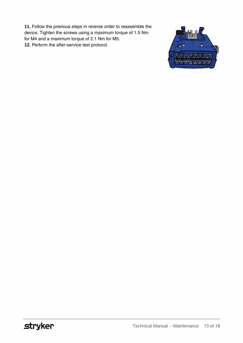
11. Follow the previous steps in reverse order to reassemble the
device. Tighten the screws using a maximum torque of 1.5 Nm
for M4 and a maximum torque of 2.1 Nm for M5.
12. Perform the after-service test protocol.

Technical Manual - Troubleshooting
3 Troubleshooting
Problem Possible Cause Action
Unplugged or damaged power
cord
Make sure power cord is
plugged in and is undamaged.
Replace cord if necessary.
(See Mistral-Air® Warming Unit
User Manual.)
No power to outlet Confirm power to outlet.
Poor or loose wire connections Ensure all connectors and
terminals are secure.
The device does not switch on.
Blown fuses at PCBA Replace fuse(s). (See
Replacing the fuses on page
9.)
Obstructed air flow path
Poor or loose wire connections,
or damaged heater or
electronics
The technical alarm is activated
and the warming device
stopped working.
Large mains power dip (≥ 30%)
for more than 1/60 of a second
If this alarm occurs, check for
anything blocking the air flow
path (e.g. blocked inlet, blocked
hose end, or kink in the hose).
Remove the obstruction(s),
unplug the device from mains
power, reconnect it and verify
the alarm is gone. Press
standby to activate the device
again. In case of a recurring
alarm, open the device and
check for internal damage or
loose connectors. If no damage
is found, contact Stryker for
support.
The microcontroller watchdog
alarm is activated.
Malfunctioning electronics Open the device and check
for internal damage or loose
connectors. If no damage
is found, contact Stryker for
support.
Obstructed air flow path Check for anything blocking the
air flow path and remove the
obstacles.
The device does not deliver
enough air.
Clogged air filter See Mistral-Air® Warming Unit
User Manual to replace the
filter with new filter supplied by
Stryker.
Technical Manual - Troubleshooting
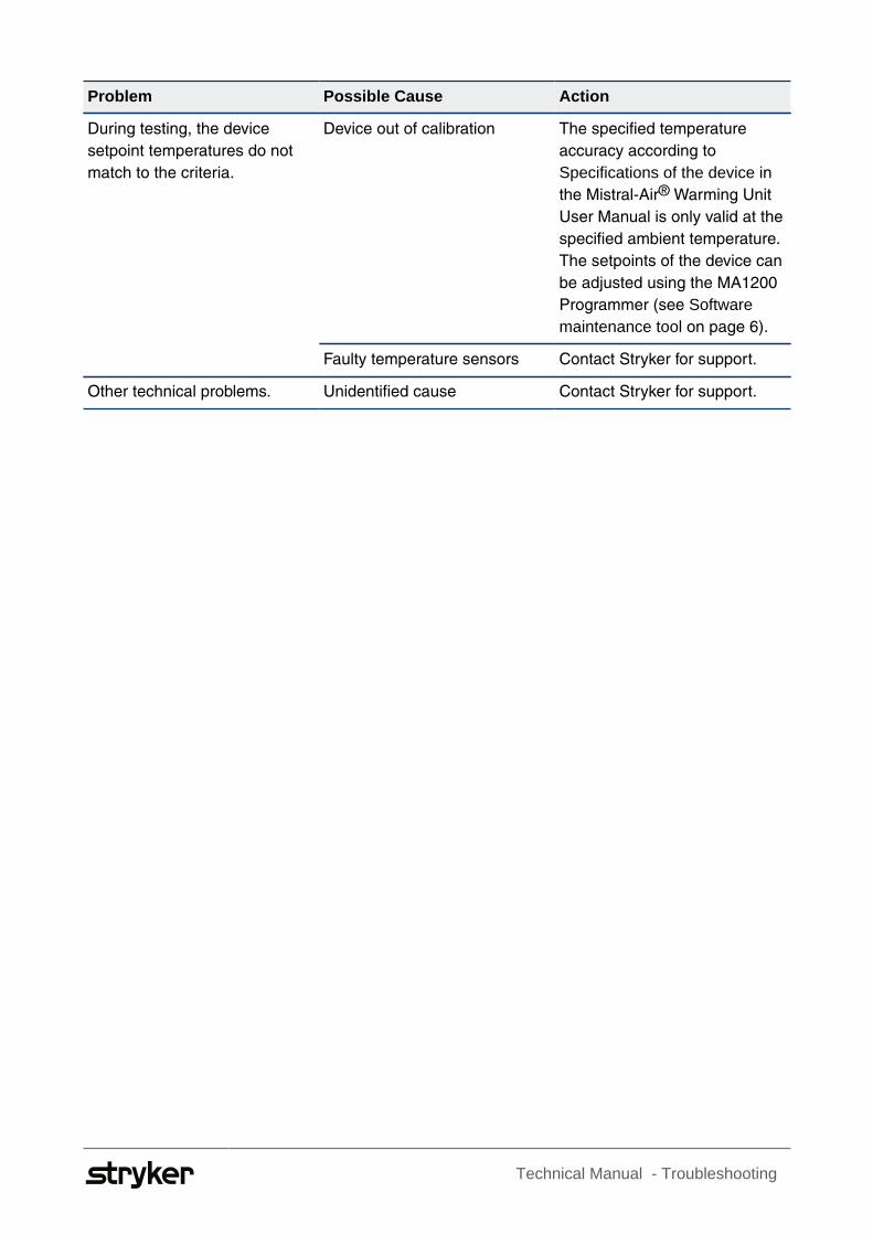
Problem Possible Cause Action
Device out of calibration The specified temperature
accuracy according to
Specifications of the device in
the Mistral-Air® Warming Unit
User Manual is only valid at the
specified ambient temperature.
The setpoints of the device can
be adjusted using the MA1200
Programmer (see Softwaremaintenance tool on page 6).
During testing, the device
setpoint temperatures do not
match to the criteria.
Faulty temperature sensors Contact Stryker for support.
Other technical problems. Unidentified cause Contact Stryker for support.

Technical Manual - Appendices 16 of 18
4 Appendices
4.1 After-service test and preventive maintenance form
Hospital
Location
Serial Number
Date
Test Engineer
Signature
Test Conditions Check
Test object Temperature (°C) Acceptable range (°C)
Ambient temperature 20.5 – 23.5
Draft free room Pass ❏ Fail ❏
No air outlet obstructions Pass ❏ Fail ❏
Free air inlet Pass ❏ Fail ❏
No air conditioner / climate
control
Pass ❏ Fail ❏
Pass ❏ Fail ❏
Comment:
Electrical safety test
During the electrical safety test, maximum values of continuous leakage and patient auxiliary
currents must be measured according to the following table:
Current Type Body Floating (BF)
Maximum values [µA](Normal Condition(NC))
Measured [µA] Pass/Fail Normal
Earth leakage current
general
500 Pass ❏Fail ❏
Cabinet leakage 100 Pass ❏Fail ❏

Technical Manual - Appendices 17 of 18
Control Panel Test
LED's flashing Pass ❏ Fail ❏
Audible alarm Pass ❏ Fail ❏
Switch on at setpoint 38 °C Pass ❏ Fail ❏
Button check Pass ❏ Fail ❏
Setpoint temperature check
Selected setpoint Temperature (°C) Acceptable range (°C)
43 42.5 – 47.5
38 37.5 – 42.5
32 31.5 – 36.5
Pass ❏ Fail ❏
Comment:
Overtemperature alarm test
Test object Temperature (°C) Acceptable range (°C)
Overtemperature alarm Below 56
Pass ❏ Fail ❏
Alarm suppression button Pass ❏ Fail ❏
Impossible to start using
standby button
Pass ❏ Fail ❏
Device starts normally Pass ❏ Fail ❏