technical memorandum traffic management … tm… · technical memorandum traffic management center...
TRANSCRIPT

Technical Memorandum
TRAFFIC MANAGEMENT CENTER VISUALIZATIONSMART SunGuide TMC, Broward County, Florida
Prepared forFlorida Department of Transportation, District IVTransportation System Management & Operations Consulting ServicesContract Number: C8V80
Prepared by
July 2010
In association with Cambridge Systematics, Inc.

Transportation Systems Management & Operations TMC Visualization
July 14, 2010
TABLE OF CONTENTS 1.0 INTRODUCTION 1
2.0 DEFINITION OF FUNCTIONS 1
2.1 EXISTING TMC FUNCTIONS 2 2.2 TMC SURVEYS 3 2.3 FDOT DISTRICT FOUR INPUT 12 2.4 BROWARD COUNTY TRAFFIC ENGINEERING DIVISION INPUT 13 2.5 FUTURE TSM&O FUNCTIONS 14
3.0 TMC WORKSTATIONS 18
3.1 ITS REGIONAL ARCHITECTURE 18 3.2 TMC WORKSTATION RECONFIGURATION 20
4.0 TMC VIDEO WALL 26
5.0 TSM&O STAFF JOB DESCRIPTION 31
6.0 SUMMARY 32
APPENDICES APPENDIX A – TMC SURVEY 33
APPENDIX B – SUMMARY OF TMC SURVEYS 37
APPENDIX C – TMC INTERVIEWS 41
LIST OF EXHIBITS
Exhibit 1 - Southeast Florida Regional ITS Architecture 19 Exhibit 2 - Southeast Florida Regional ITS Architecture Components 20 Exhibit 3 - SMART SunGuide TMC (Existing Workstation) 21 Exhibit 4 - Control Room Workstation Layout (Existing) 22 Exhibit 5 - Add an additional 4th row in the front 23 Exhibit 6 - Reconfigure all rows and add an additional 4th row in the front 24 Exhibit 7 - Add an additional workstation on each end of Row 1 and 2 (Option 3) 25 Exhibit 8 - Recommended TSM&O Workstation Configuration 26 Exhibit 9 - Current TMC Video Wall Configuration 28 Exhibit 10 - Proposed TSM&O Video Wall Configuration (Routine Traffic) 28 Exhibit 11 - Proposed TSM&O Video Wall Configuration (Incident Event) 28 Exhibit 12 – Rendering of Proposed TSM&O Video Wall (Routine Traffic) 29 Exhibit 13 - Rendering of Proposed TSM&O Video Wall (Incident Event) 30

Transportation Systems Management & Operations TMC Visualization
July 14, 2010 Page 1
Transportation Systems Management & Operations
TMC Visualization
1.0 INTRODUCTION
The SMART SunGuide Transportation Management Center (TMC) is currently staffed by operators representing the Florida Department of Transportation (FDOT) District Four to manage the freeways; the I-595 Concessionaire to manage the section of I-595 between I-75 and I-95; and the Broward County Traffic Engineering Division (BCTED) to manage operations of the computerized signalization system. While the current focus of the TMC is on incident management and detecting / responding to signal system malfunctions, the focus of the Transportation Systems Management & Operations (TSM&O) program is on improving the integration of operations among the freeway, arterial and transit systems within Broward County. Therefore, the TMC will need to provide more of a balance in conducting proactive traffic / transit management as well as incident management.
The following research was conducted in suggesting recommendations to reconfigure the SMART SunGuide TMC to support the needs of the TSM&O program:
• Functions – Define the functions that the TMC will be responsible for as part of the TSM&O program. Five TMCs were surveyed to determine how they address TMC operations and provide suggestions regarding reconfiguration of the video wall and workstations to support the goals of the TSM&O program.
• Workstations – Develop a concept of how the computer consoles would be reconfigured to support the TSM&O requirements. This includes development of a conceptual system architecture, sketch and rendering to illustrate the layout for a typical TSM&O console.
• Video Wall – Develop a concept of how the video wall would be used during routine operations (i.e., default mode) as well as during an incident event.
• Staffing – Develop a job description for TSM&O staff to be assigned to the TMC to support traffic operations, safety and mobility management as well as incident management. The job description was developed in a format consistent with the TMC Standard Operating Guidelines.
The results of this study should be presented to the TSM&O Committee for their concurrence and integrated into the TSM&O Concept of Operations.
2.0 DEFINITION OF FUNCTIONS
This section describes the existing functions that operations staff at the SMART SunGuide TMC is responsible for; the results of a survey conducted of other TMCs throughout the nation; input received from FDOT District Four TMC Operations and BCTED Operations; and a summary of

Transportation Systems Management & Operations TMC Visualization
July 14, 2010 Page 2
potential additional functions that may be required in supporting the needs of the TSM&O program.
2.1 Existing TMC Functions The operations staff at the SMART SunGuide TMC is primarily responsible for the following functions: • Incident Management – TMC operators are responsible for receiving and collecting
incident information; documenting, activating and updating information into SunGuide software; dispatching Road Rangers if not already on scene; notifying emergency agencies and providing updates; posting messages, updating messages and blanking dynamic message signs; sending and updating incident email alert notifications; locating incidents via CCTV cameras and entering camera numbers and presets into the system; and monitoring changes / request updates from Road Rangers.
• Road Ranger Management – Although the Road Ranger Contractor manages their activities, the TMC provides dispatching support. This encompasses monitoring information on Road Ranger schedules, rotation tow, abandoned vehicles, debris incidents, driving on the shoulder and in a High Occupancy Vehicle (HOV) lane, FHP disabled vehicles, incidents with injuries and/or fatalities, missing/malfunctioning equipment, Road Ranger accident involvement, Maintenance of Traffic (MOT) as well as procedural errors documentation.
• Emergency Management – The TMC operator’s role prior to, during and after an emergency varies based on the type and severity of the emergency. For a hurricane, the TMC operators are responsible for the following activities after the storm: advising all Road Rangers and SIRV operators to watch for power lines that could be entangled in debris or in disabled/abandoned vehicles; advising all Road Rangers not to drive through or walk through flooded areas; watching for debris on the roadway and cautioning Road Rangers that debris could contain sharp objects; and continually monitoring all CCTV cameras.
• Special Event Management – TMC operators are responsible for supporting special event management, including posting advanced messages on dynamic message signs (DMS) and monitoring impacts along roadways within the system.
• Equipment Failure Monitoring – The TMC operations staff monitors the “health status” of the Intelligent Transportation System (ITS) and signal system equipment in the field. This includes the status of the traffic signals, CCTV cameras, DMSs, vehicle detectors and communications. Equipment failures are reported through the “trouble ticket” process.

Transportation Systems Management & Operations TMC Visualization
July 14, 2010 Page 3
• Roadwork Event Management – The TMC provides assistance for roadwork events such
as dispatching Road Rangers to verify the roadwork and posting messages on DMSs. Depending on the length of roadwork event and the possibility that the lane blockage pattern may change without notification from contractors, TMC operators are responsible for monitoring the event at least once per hour via CCTV cameras to confirm no changes to the lane blockage patterns. In addition to monitoring the roadwork incident, the TMC operator should also monitor traffic before, at and beyond the roadwork incident. With every event checked on, they confirm with the verification resource (i.e., CCTV camera or assigned Road Ranger) and make a note in the comment section of the SunGuide software database indicating the confirmed location and whether or not there were any changes to the lane blockage.
• Traveler Information – TMC operators are responsible for entering lane closure event
information into the SunGuide software in accordance with quality control requirements.
• Amber / Silver / LEO Alerts – The TMC operator is responsible for posting Amber, Silver and LEO alerts in accordance with the Standard Operating Guidelines in response to Florida Department of Law Enforcement (FDL&E) direction.
2.2 TMC Surveys Surveys were conducted of the following TMCs to determine how they address operations and to provide suggestions regarding reconfiguration of the video wall and workstations to support the goals of the TSM&O program:
• Georgia Navigator TMC (Atlanta, Georgia) • FAST TMC (Las Vegas, Nevada) • Houston TranStar (Houston, Texas) • Guidestar (Minneapolis, Minnesota) • Joint Traffic Management Center (New York City, New York)
Each TMC participant completed a written survey that was subsequently followed-up with a telephone survey. The survey instrument, completed surveys and summaries of telephone interviews are presented in the Appendix. An overview of each TMC and suggestions are presented below.
2.2.1 Georgia Navigator TMC (Atlanta, Georgia)
The Georgia Navigator TMC is a 50,000 sf facility that encompasses space for the control room, computer room; voice communications patch panel; large screen video wall; office planning / administrative personnel; facilities to accommodate multiple agency meetings (including the press); facilities to accommodate overnight stays by Emergency Management Agency (EMA) staff, and an underground garage. The operations staff at the TMC consists of 3-5 Georgia DOT operators during peak traffic hours and two operators at all other times. Traffic engineering staff is present on all shifts except the night shift.

Transportation Systems Management & Operations TMC Visualization
July 14, 2010 Page 4
At the foundation of the system is a distributed- computer architecture based on servers and remote workstations. Open-software architecture and a Geographic Information System (GIS) base map are central to the system design. The open architecture and communications network allow for integration with other TMCs. The distributed architecture allows participating agencies to convert any personal computer on the network to a scaled-down version of the control center operator workstation by emulating a terminal. One workstation and keyboard at each operator workstation controls all of the field equipment. The Navigator system performs monitoring and surveillance of the roadways using the following ITS field equipment: approximately 500 CCTV cameras; 1,645 Video Vehicle Detection Cameras; 97 DMSs; 140 ramp meters; and Highway Advisory Radio (HAR) Systems. All of the centers within the Atlanta region are connected via a fiber optic backbone. Variable speed limit signs on Interstates are also used based on traffic and weather conditions.
The following suggestions, related to the FDOT District 4 TSM&O program, were shared as presented below:
• Recommend reconfiguring the control room in accordance with a strategic vision.
• A distributed architecture would enable satellite TMCs to be located at mobility hubs
elsewhere.
• Include a Traffic Engineer within the control room.
• Apply TMC generated data in a proactive manner in developing intelligent systems to support decisions regarding ITS deployment, DMS messaging of high incident locations, travel time messaging and construction planning / decisions.
• Post a traffic flow map on the video wall. • Integrate the traffic signal system into the statewide TMC software. This will need to be
addressed by the SunGuide Software Configuration Management Board.
2.2.2 Fast TMC (Las Vegas, Nevada)
The FAST TMC was opened in 2005 and is operated by the Regional Transportation Commission of Southern Nevada (RTC). The RTC operates the freeway and arterial system

Transportation Systems Management & Operations TMC Visualization
July 14, 2010 Page 5
which includes approximately 1,500 signals (1,000 on-line); 200 CCTV cameras (1/2 mile spacing); 40 DMSs (every 2-3 miles); 35 ramp meters (expanding to 75 ramp meters during the next two years to cover most Interstate ramps); and vehicle detectors (i.e., side-fire radar) spaced at 1/3 mile intervals. The communications infrastructure is hybrid: fiber optics (i.e., 30 miles) and wireless (radio). 511 traveler information is generated by the integrated software and posts travel time messages on the DMSs automatically (i.e., 5 minute updates). They maintain a traffic flow map (i.e., green, yellow, red) which is posted on the www.rtcsnv.com web site. They use integrated software for freeway / arterial operations. The Emergency Operations Center is located on the 2nd floor overlooking the control room and is used for special events (e.g., New Years Eve) and emergencies. RTC operators rely on the signal system software and field observations to adjust signal timing (i.e., offsets, lead/lag, splits, coordination) and make adjustments ”on-the-fly” when necessary (i.e., do not rely solely on Synchro). RTC uses Transit Signal Priority for their BRT buses; however, this is performed automatically without operator control. Similarly, ramp meters are automatically controlled (i.e., time of day) with operators only providing control (e.g. extended green time to flush out long queues) when necessary. The FAST TMC includes ten workstations for RTC freeway & arterial operations and another 10 workstations for law enforcement (Nevada Highway Patrol) that monitor police chases among other activities. Approximately 30 client workstations are located within the TMC where various staff could pull up the same information. The police use a separate software system; there is no Computer Aided Dispatch interface for video detection as the two agencies are co-located. RTC staffing ranges from one operator during the slow periods (i.e., weekends) to 4-5 operators during peak periods (i.e., 1pm – 4pm). The working relationship between RTC and police is very good. The police posts messages on DMSs during periods when RTC does not have staff present at the TMC (e.g., nights). RTC discussed a “pod” arrangement of the workstations in the past; however, they favor the current “row” arrangement so that operators can better view the video wall. The stations are also used by field technicians to monitor system health; diagnose problems; and call-in fixes. Cross-training is provided among operations staff and field technicians. The FAST TMC does not have an established performance measure program in place. The TMC video wall is composed of 50” monitors arranged in a configuration of four rows by nine columns. The operators have full control of the video wall which is configurable based on their needs. For example, the video wall is arranged differently for day versus night shifts based on their specific needs. The video wall includes images of freeway traffic, arterial traffic, ramp metering, weather maps and news stations. The TMC operators post visibility warnings and advisories based on weather conditions.

Transportation Systems Management & Operations TMC Visualization
July 14, 2010 Page 6
The RTC workstations include three monitors: one for video images; one for freeways; and one for arterials. The RTC does not anticipate changes to either the workstations or video wall configurations as the operators are satisfied with the current arrangement. Express Lanes have been designated along Interstate 15; however, there are no vehicle restrictions in using the lanes and no physical barrier from entering / exiting the lanes. They are intended to be used for longer trips. Conversion to HOT lanes (with paddle separation) in the future is possible; however, it is not supported by the current legislature. The Express Lanes are being extended from 5 miles to 21 miles during the next few years. Although the RTC does not have a traffic engineer assigned to the control room, they support the concept. The traffic engineer would have the ability to observe and record arterial and ramp metering operations; to analyze and make improvements; and call-in the changes from the TMC. They do not have plans for Active Traffic Management; reversible lanes; or lane control signals. RTC shares video images with the media (i.e., TV and radio), local government agencies and internet using streaming video. Dedicated Work Zone ITS equipment is being used during major Interstate reconstruction. The workstation software is integrated with the FAST software.
The following suggestions, related to the FDOT District 4 TSM&O program, were shared as presented below: • TMC operator / technicians should have the ability to adjust signal timing coordination
“on-the-fly” rather than solely depending on the results of traffic simulation models. • Video wall and workstation configuration recommendations should be based on input
received from TMC operators / technicians. • TMC software should provide for integrated control of freeways and arterials.
2.2.3 Houston TranStar (Houston, Texas)
Houston TranStar is a partnership that was formed based on the need for transportation and emergency management agencies within the Houston area to coordinate their sometimes overlapping activities. The Houston TranStar consortium is comprised of: the Texas Department of Transportation (Texas DOT), City of Houston, Harris County, and Metropolitan Transit Authority (Metro). TranStar, through its shared TMC, coordinates the operation of the regional ITS along the freeway and HOV system as well as the Regional Traffic Control Signal System (i.e., 2,800 signals) and real-time monitoring of light rail operations. Police, emergency and transit dispatch functions are located within the TMC in order to optimize response to incidents. Freeway and incident management functions are controlled

Transportation Systems Management & Operations TMC Visualization
July 14, 2010 Page 7
by operations staff within the facility. TranStar agency managers assigned to the TMC include: Emergency Management Deputy Coordinator (Harris County); Manager, Transportation Management Systems (Texas DOT); Captain, TranStar Division (Metro); Manager, Transportation Management Systems (Metro); Information Resources Administrator (Texas DOT); Emergency Management Deputy Coordinator (City of Houston); Traffic, Deputy Assistant Director (City of Houston); and Information Service Providers (Metro Traffic, Traffic.com). All CCTV cameras are controlled via the TMC. In addition, all DMSs, Lane Control Signals (LCS) and Flow Signals (i.e., ramp meters) are controlled from the TMC. TranStar also uses two types of vehicle detection technologies – roadway loop detectors and Automated Vehicle Identification (AVI). Finally, as a public service to motorists traveling within the Houston metro area, a public/private partnership provides a free Motorist Assistance Program (MAP) consisting of 16 service vans. This public/private partnership consists of the Harris County Sheriff’s Department, Texas DOT, Metro, the Houston Automobile Association and Houston Cellular Telephone. The 52,000 sf Houston TranStar facility currently houses the following: 4,200 sf control room; conference room/command center that overlooks the main operations center; computer room; communications room; offices for Texas DOT, police and approximately 110 personnel (normal operations); and maintenance and storage rooms. A video wall displays maps and video to personnel within the control room and in observation rooms adjacent to the control room on two of the three floors of the facility. The video wall consists of a matrix of rear projection screens with thin borders around each screen. The thin-bordered design has brightness and clarity advantages over large rear screen projectors. The video wall consists of four separate panels. The system is capable of displaying from one to four separate video displays on each of the panels. A single video signal can cover the entire panel, or parts of the screen can display separate video images or dynamic maps. These dynamic maps display speed, volume and occupancy data for roadway links and are updated by the system in real time. The mainframe computer controlling the system is located at the TMC. The TranStar system architecture is based on a client-server computing system. The system software provides the operator with interfaces to the system. It also collects data from the various field devices, then assembles and analyzes the data in a central location. This is performed, in part, via a large, centralized database of integrated traffic data. The original core systems were developed using widely recognized industry standards to allow future projects to be integrated into TranStar and continually expand its capabilities.

Transportation Systems Management & Operations TMC Visualization
July 14, 2010 Page 8
The system provides surveillance and control of the following field devices: 661 CCTV cameras; 201 DMSs; 12 HAR transmitting locations; Lane Control Signals; loop and radar vehicle detectors, 85 ramp meters; 2,800 Traffic Signals; and MAP Service Patrol Vehicles. As previously mentioned, the freeway management system utilizes dual AVI technologies, Global Positioning System (GPS) and dead-reckoning. Over 800 directional miles of roadway is covered with AVI reader stations that track roadway link speeds and assist in the production of a travel speed map for the Houston area freeways. This map is then used for traffic management and incident detection. The TranStar system also receives real-time communications, including voice, data and live video. The TranStar telecommunications network can be utilized by area hospitals to transmit real-time video and other data from ambulances in navigating optimal travel routes. TranStar provides real-time traffic information to travelers via its Internet web page. Westwood One is the private traffic reporting services firm which utilizes the TMC to broadcast traffic updates through the local media. A fiber optic communications network is the backbone of the transportation management functions controlled by TranStar. All communications between the TMC and field components listed above occur through this network. The ultimate length of the communications network system will include over 300 miles of fiber optic cable. The following suggestions, related to the FDOT District 4 TSM&O program, were shared as presented below:
• TranStar is increasing the number of workstations (with four monitors at each work
station) from 36 to approximately 80 by reconfiguring the monitors to use smaller consoles with adjustable arm trees as well as physical space expansion by eliminating some adjacent rooms.
• It is suggested that a buffer be provided to accommodate expansion of the number of
workstations if other partners are co-located in the future. For example, as the transit system grows, it requires significant expansion of operator positions within the control room when co-located within the TMC.
• Possibly include security surveillance at transit stations, parking facilities and bus stops as
an additional function of the TMC. • Consider using shoulders for emergency evacuation and congestion management. This
will require monitoring by the TMC. • Include a Traffic Engineer within the control room.
2.2.4 Guidestar TMC (Minneapolis, Minnesota)
The Minnesota DOT (MnDOT) has undergone several reorganizations during the past eight years. Prior to 2002, their Central Traffic Office consisted of the traditional traffic

Transportation Systems Management & Operations TMC Visualization
July 14, 2010 Page 9
engineering support functions, safety, signals & lighting, signing and standards. During 2002, MnDOT’s Office of Advanced Technologies (ITS) merged with the Office of Traffic Engineering. Subsequently, their TMC for the Twin Cities Metropolitan area and Electrical Services Section were merged into their Office of Traffic Engineering. This change occurred at the same time that their new RTMC opened. The RTMC manages Metro freeway traffic and includes operational management, incident response, ITS design, system integration and development of their Transportation Operations Communication Centers. At the same time, they took over the role of Homeland Security (at the RTMC) and took on the lead role for developing their work zone standards. As a result of these changes, their name was changed to the Office of Traffic, Security and Operations.
In 2003, the Minnesota DOT opened their new RTMC adjacent to the District headquarters. The primary purpose of this facility is to integrate DOT's Metro District Maintenance Dispatch and DOT's Office of Traffic, Security and Operations with the Minnesota Department of Public Safety's State Patrol Dispatch into a unified communications center. The integration provides the communications and computer infrastructure necessary for coordinated transportation management on metro freeways during normal commuting periods, as well as during special events and major incidents. The RTMC video wall is 105” x 418” and includes a mini-wall with 12 monitors for DOT Maintenance and Highway Patrol’s use.
The backbone of the Minnesota DOT's RTMC is the Operations Center. RTMC staff confirms traffic incidents with nearly 285 CCTV cameras posted along 210 miles of metro-area freeways. Information on incident location and resulting traffic back-ups are relayed to travelers via Traffic Radio, Traffic TV, various Internet sites and a telephone service. The RTMC provides traffic information to local radio and television traffic reporters as well. Travelers are also alerted to traffic problems via 70 DMSs placed throughout the freeway system.
RTMC staff also uses CCTV cameras to verify that the 430 ramp meters are responding to real-time traffic conditions. The RTMC's 3,700 loop detectors provide computers the information needed to determine ramp meter timing. Loop detectors also measure traffic speeds, which are displayed on a graphics map on Traffic TV and various Internet sites. RTMC components include the following: surveillance via CCTV cameras and loop detectors; ramp meters; DMS; lane control signals; Traveler Information Program; High Occupancy Vehicle (HOV) / High Occupancy Toll (HOT) System; Incident Management Program; FIRST Program (i.e., service patrols); and research and development.
The Traffic Operations unit is responsible for managing traffic on the Twin Cities metro freeways with the use of ramp meters, DMSs, lane control signals and loop detectors. The results are improved incident management and traveler information.
Transportation Systems Management & Operations TMC Visualization
July 14, 2010 Page 10
The RTMC is staffed Monday through Friday from 5:30 am to 8:30 pm, Saturday from 10 am to 6 pm, and on Sunday from 11 am to 7 pm. They monitor traffic conditions, assist in incident management and provide traveler information.
Traffic Operations staff also continually perform systems analysis of field equipment, the ramp meter algorithm and RTMC equipment. They also analyze and research traffic flow trends, new technologies and other issues that affect congestion.
The Minnesota DOT Metro District's Signal Operations unit is responsible for the construction, inspection, operation, and timing of the traffic signals on the trunk highway system within the Twin Cities metropolitan area. The Signal Operations unit operates nearly 700 signals, most of which are owned by the State of Minnesota.
Signal Operations staff provides support to the Construction unit by providing quality control and inspection, coordinating signal turn-ons and coordinating activities between signal operations, Electrical Services Section and contractors. The Signal Operations staff is responsible for the timing and operation of all traffic signals. This involves developing timing and coordination plans, responding to customer complaints and inquiries, monitoring system performance and detecting operational and maintenance problems. The Signal Operations unit also assists other units in signal related training and in developing techniques and procedures in signal operations and construction.
Maintenance Dispatch serves as a point of contact for incoming information. The Metro District Communication Center exists to provide communications 24 hours/day for the Metro District. Staff handles phone calls and monitor electronic communications and the bridge de-icier system, roadway surface and sub-surface systems. They document and respond with appropriate personnel for road emergencies such as snow and ice, potholes and incidents that may impact traffic flow. Maintenance Dispatch coordinates and initiates traffic management systems with the RTMC, traffic management personnel and the State Patrol. An Integrated Transportation Management System project is being planned for I-394 and adjacent arterials.
The following suggestions, related to the FDOT District 4 TSM&O program, were shared as presented below:
• Allow room for expansion and changes in technology.
• Performance measures should be displayed (e.g., % roadway congested, incident
clearance times). • Provide a traffic flow map on the video wall based on travel speed with capability for
automatic notification of incidents or congested locations.
• Plan accordingly to accommodate current and future information flow requirements among co-located partners.
• Consider the deployment of lane control signal systems to support active traffic management strategies.

Transportation Systems Management & Operations TMC Visualization
July 14, 2010 Page 11
• Consider the deployment of a system that monitors the local police Computer Assisted
Dispatch (CAD) dispatch system and alerts the TMC operator of incidents.
2.2.5 Joint Traffic Management Center (New York City, New York) The New York State Department of Transportation (NYSDOT) Region 11 Office, which covers the five boroughs of New York City, operates a Joint Traffic Management Center (JTMC). Operation of the JTMC requires a close working relationship with partner agencies: the New York City Department of Transportation (NYCDOT) and the New York City Police Department (NYPD). The JTMC controls ITS systems on some of the most congested interstate corridors within NYC and is operated seven days a week, 24 hours a day. The system covers approximately 75 miles of the state highway system, operates approximately 250 CCTV cameras; 64 DMSs; four HAR systems; and 200 vehicle detectors. In the next few years, additional systems will expand the mileage to about 120 miles of the system (out of 170 miles), providing coverage on most of the critical highways within the city. The amount of field equipment will increase at a proportional rate. The NYCDOT system includes approximately 250 CCTV cameras; 20 DMSs; more than 200 vehicle detectors; and more than 6,000 computerized traffic signals. The JTMC posts real-time traveler information onto the 511 New York public web site via the IEN (Information Exchange Network) and seasonally, on the WTA (Winter Traveler Advisory). Some roadway cameras can be viewed on the website. Other area-wide systems have been implemented by TRANSCOM, such as the Regional Architecture Database, TRANSMIT (for toll tag reader traffic detection) and IRVN (Inter-Regional Video Network). TRANSCOM has installed workstations at the JTMC that can access these systems. Another program aimed at improving multiagency coordination for incidents, IIMS (Integrated Incident Management System), also operates at the JTMC. Additionally, field units of the Highway Emergency Local Patrol (HELP), the New York State program that contracts the services of the NYPD to provide freeway service patrols on selected NYC highways, communicate with dispatchers located within the JTMC. A primary objective of the NYSDOT Region 11 ITS Program is to implement a comprehensive citywide Advanced Traffic Management System (ATMS) for the limited- access state highway network within NYC. The following suggestions, related to the FDOT District 4 TSM&O program, were shared as presented below:

Transportation Systems Management & Operations TMC Visualization
July 14, 2010 Page 12
• Workstations should be configurable to accommodate ATMS and video systems. Consider reconfiguring selected workstations to include “mini-video wall” systems.
• During routine operation (non-incidents), the TMC operators can use the monitors at their work stations, and management can use the wall, for monitoring performance measures or QA/QC.
• A large notice board should be displayed within the control room to transfer information from one shift to another.
• A traffic flow map should be displayed on the video wall to provide a real-time status of the roadway network.
• Use TMC data to monitor performance measures. • Use TMC resources in planning, coordinating and monitoring construction activities and
other events.
• All work stations (including TMC manager offices, cubicles) at the TMC should be capable of accommodating ATMS systems and CCTV video for quality control. The ATMS / Video system should be capable of more automated notification of congestion and incidents.
• Scrolling video images of congested (recurring) locations or hot spots and flow maps should be posted on the video wall during routine operation (non-incidents).
2.3 FDOT District Four Input SMART SunGuide TMC operations staff is currently reviewing how the FDOT District Four side of the video wall is being used to identify improvements to meet their existing needs. A meeting was held with the TMC management and operations staff on June 9, 2010 to discuss their near-term needs for the video wall and how they may be integrated with the needs of the TSM&O program. The SMART SunGuide TMC operations staff proposed the following suggestions as a result of the meeting: • A red box should be displayed around the border of images for Level 3 incidents.
• A traffic speed map should be displayed on the video wall.
• Video images along the bottom row should be reduced in size (i.e., quad images) and
assigned to TMC operators in the row of consoles closest to the video wall. Larger images should continue to be displayed on the middle and upper rows and assigned to TMC operators in the two rows further away from the video wall.
• Weather information should be embedded in a Level 2 and 3 alert crawl with a default
message indicating “no active incidents”.

Transportation Systems Management & Operations TMC Visualization
July 14, 2010 Page 13
• Video images should be displayed of traffic upstream of the incident in both directions. This would enable operators to view impacts caused by motorists slowing down to view the incident in the opposite direction as well as delayed vehicles within the queue.
• CCTV camera images from adjacent districts should be aligned to border the appropriate District Four image (i.e., along I-95, I-75).
• The space on the left and right sides of the video wall should be used to present text and
charts of information as well a clock.
• Critical status information should be viewable by FDOT managers, having windows adjacent to the control room, from their offices.
• Speed profile charts should be displayed on operator consoles rather than the video wall.
• Alarms should be used to indicate a system failure.
• A monitor should be used to display CNN news with closed captions.
• A weather map should be displayed showing local weather.
• Video images should be displayed for adjacent counties (i.e. Miami-Dade, Palm Beach, and
Collier Counties).
• Display video images along the interstates all in one direction of travel on one row, and the opposite direction on another row.
• Incorporate a scrolling message system displaying information on active incidents.
• Begin using roving images on the freeway side of the video wall. The general consensus of the SMART SunGuide TMC operations management and staff was that they prefer displaying more highway cameras on the wall rather than data, charts and maps. Also, they supported the concept of using a double-stack of monitors on their consoles to have a close-up view of cameras within their zone.
2.4 Broward County Traffic Engineering Division Input The Broward County Traffic Engineering Division (BCTED) was presented with an overview of the video wall concept from a TSM&O program perspective on May 21, 2010. BCTED’s input is summarized below: • The video wall should be divided into three sections: FDOT interstate monitoring
operations, Broward TSM&O monitoring, and BCTED Signal Operations.

Transportation Systems Management & Operations TMC Visualization
July 14, 2010 Page 14
• Under Routine Traffic Conditions, there is a need for several signal system related features, including a Signal System Communications Status Map; statistical reports from the new signal system software platform; and statistical reports from the communications monitoring software.
• A minimum of three larger screens are needed for selecting feeds from their video detection
management system to check the operation of detection at selected intersection approaches.
• Due to the renewed emphasis on countywide arterial retiming efforts, it is desired to
reserve at least six screens to remotely view conditions along corridors that are in the process of an arterial signal retiming effort. This could be either VIDS or CCTV camera feeds depending upon what is available along the specific corridor.
• Reserve a bank of six selectively “roving” CCTV cameras on the surface arterial network.
These may be combined with the six signal retiming feeds based on project needs.
• For system incident events that impact the signalized arterial network, or for which signal timing modifications can assist in incident detouring & mitigation, the following video wall views are suggested:
The Video Detection Management System Feeds # 1 and #2 would be selected/reverted
to “ACTIVE INCIDENT Feeds “A” & “B”” to cover the signalized intersection approaches most impacted by the incident.
Video Detection Management Video Feed #3 would be converted to a display of real-time signal timing operations at the most impacted signalized intersection (terminal desktop display from the new signal software).
The feeds previously used for signal retiming efforts would be reverted to available VIDS and/or CCTV feeds covering incident or detour corridors.
The “roving” video feeds could be used to supplement incident coverage as needed based on the severity of the incident.
2.5 Future TSM&O Functions Based on the goals and objectives of the TSM&O program and input received from the TMC surveys, as well as FDOT District Four and BCTED, the following functions are recommended:
• Congestion Management – Monitor congested segments of the TSM&O network in
terms of travel speed, delay, volume and occupancy. Analyze and implement the appropriate congestion mitigation measure based on off-line simulation analyses.
• Express Lanes Operations – Monitor travel speed, volume, and occupancy of express lanes, then adjust dynamic tolls every 15 minutes in accordance with recommendations

Transportation Systems Management & Operations TMC Visualization
July 14, 2010 Page 15
generated by the “Express Lanes Manager” software module to maintain minimum travel speeds of 45 mph within the express lanes.
• Ramp Metering Operations – If and when ramp metering is implemented within District Four, traffic delays and queuing impacts along impacted roadways and signalized intersections need to be monitored. TMC operations need to be proactive in increasing the release rate at locations where queues extend beyond the ramp into adjacent arterials and intersections.
• Active Traffic Management Operations – If and when active traffic management is implemented within District Four, traffic operations staff will need to monitor traffic speeds, volumes and delays that serve as triggers to activate hard-shoulder running. Once these minimum thresholds are met, the traffic flow needs to be monitored to determine if this is a consistent pattern (or just a temporary aberration); then use the CCTV cameras, along with Road Rangers, to sweep the shoulders before activation. In addition, lane control signals should be activated to post appropriate speed limits to support the safe transition in activating and deactivating hard-shoulder running.
• TSM&O Network Monitoring – TMC operations should monitor the TSM&O network to identify system failures and roadway segments approaching critical thresholds of performance. Mitigation measures should be analyzed off-line, with the optimum strategy implemented prior to exceeding the threshold. Furthermore, other analytical tools can be applied to compare the quality of traveler information provided by private sources (e.g., Google, INRIX, etc.) with TMC generated data to determine whether these private sources can be used to replace extensive traffic detection infrastructure systems.
• Traffic Engineering – A Traffic Engineer(s) should be assigned to the TMC to conduct traffic operations and safety studies in a proactive manner utilizing the data and video images being generated at the TMC. This will enable traffic engineers to be more efficient in conducting necessary data collection, identifying and analyzing “hot spots”; developing and implementing mitigation measures in a real-time manner, such as implementing signal timing changes; and performing before and after analyses of implemented improvements.
• Incident Detection System – TMC operators should monitor the local police CAD system to identify incidents on the TSM& O network.
• Decision Support System – TMC operations staff should develop and apply decision support systems that utilize archived data to automatically predict and identify “hot spot” locations (i.e., traffic congestion, high incident locations, high crash locations, and transit delays); generate an array of potential solutions; analyze these solutions based on adopted measures of effectiveness; and recommend the preferred strategy for implementation.
• Signal Timing Changes – TMC operations staff should have the ability to download traffic signal timing changes from the TMC based on traffic simulations (e.g., Synchro) or based on observations of problems identified using CCTV cameras and detection data.

Transportation Systems Management & Operations TMC Visualization
July 14, 2010 Page 16
• Performance Measures – TMC operations staff should utilize adopted performance
measures to proactively manage the TSM&O network in terms of mobility, congestion and safety. This should be performed using dashboards at their workstations, as well as on the video wall, as part of their core functions.
• Maintenance Support – FDOT ITS and BCTED maintenance technicians are based at the
SMART SunGuide TMC and have access to information which reports on system availability / malfunctions of equipment in the field. In addition, other roadway and bridge maintenance staff may benefit from sharing TMC generated data and video in identifying deficiencies; deploying maintenance staff and contractors to make repairs; and monitoring repairs using CCTV cameras. This would require providing maintenance staff with monitors located in their offices that mimic the data and images of the TMC.
• Transit AVL Monitoring – TMC operations staff should monitor the performance of BCT
busses, SFRTA trains and community shuttles in terms of their schedule adherence. This is critical in optimizing trip reliability; minimizing transfer times between modes; and reducing overall “door-to-door” travel times. “Door-to-door” travel time is the aggregate time it takes to travel from a traveler’s point of origin (e.g., home) to their destination (e.g., office). TMC operations staff should work with the transit agencies in supporting transit signal priority strategies as a tool for transit schedule recovery. In addition, TMC operators should share information related to incidents and congestion with transit agencies, so they can implement appropriate measures, such as rerouting buses to avoid delays. Furthermore, CCTV cameras within busses and at bus stops should be monitored to improve passenger security.
• TV News / Weather Monitoring – TMC operations staff should monitor TV news and weather reports to be proactive in preparing and managing adverse events such as emergency evacuations. The TMC should play a key support role in coordinating with emergency response agencies within the region and post messages related to visibility, wind and/or adverse weather conditions. The advantage of “TV News / Weather Monitoring” is having advanced information on pending emergency events (e.g., hurricanes) as well as having another source of information to identify and monitor major incidents and lane closures. The disadvantage is the distraction of operators watching TV during slow periods.
• Railroad Crossing Monitoring – TMC operations staff should monitor FEC and CSXT
railroad crossings along the TSM&O network to provide advanced notice to travelers about a long freight train blockage (e.g., more than 5 minutes) at a railroad crossing and help implement signal timing changes to flush out traffic queues resulting from delays. The CCTV cameras and detection systems provide tools to observe unusually long queues resulting from abnormally long railroad crossing closures. The intent is to use these tools to “flush out” long traffic queues by downloading “on-the-fly” signal timings to extend the green times for those critical movements needing it the most considering delays in all directions rather than solely relying on the default signal timing plan residing within the controller.

Transportation Systems Management & Operations TMC Visualization
July 14, 2010 Page 17
• Drawbridge Crossing Monitoring – TMC operations staff should monitor Intracoastal Waterway Drawbridge crossings along the TSM&O network to provide advanced notice to travelers about a long bridge opening (e.g., more than 5 minutes) and to flush out traffic congestion queues resulting from the delays.

Transportation Systems Management & Operations TMC Visualization
July 14, 2010 Page 18
3.0 TMC WORKSTATIONS
Reconfiguration of the TMC workstations and video wall should be consistent with the adopted Southeast Florida ITS Regional Architecture as well as the 2015 Update ITS Strategic Business Plan.
3.1 ITS Regional Architecture
The Southeast Florida Regional ITS Architecture is a roadmap for transportation systems integration within Southeast Florida over the next 20 years. The ITS Architecture has been developed through a cooperative effort by the region's transportation agencies, covering all modes. The initial regional ITS architecture was developed from the existing ITS architecture and documentation gathered from stakeholders. This final draft of the regional ITS architecture takes into account input from a two-day stakeholder meeting held on June 23-24, 2005, and a confirmation workshop held on August 23, 2005.
The Statewide and Regional ITS Architectures represent a shared vision of how each agency’s systems will work together in the future, sharing information and resources to provide a safer, more efficient, and more effective transportation system for travelers in the State.
The Statewide and Regional ITS Architectures have a time horizon of up to twenty years with particular focus on those transportation elements likely to be implemented in the next ten years. The ITS architecture covers the broad spectrum of ITS, including Traffic Management, Transit Management, Traveler Information, Maintenance and Construction, Emergency Management, and Archived Data Management over this time horizon.
The ITS Architecture presented in Exhibit 1 and Exhibit 2 was extracted from the approved Southeast Regional ITS Architecture developed in 2001 and recently updated on March 10, 2010.

Transportation Systems Management & Operations TMC Visualization
July 14, 2010 Page 19
Exhibit 1 - Southeast Florida Regional ITS Architecture

Transportation Systems Management & Operations TMC Visualization
July 14, 2010 Page 20
Exhibit 2 - Southeast Florida Regional ITS Architecture Components
Archived Data Management Information Service Provider Roadway Subsystem Care Facility FDOT D4 Data Warehouse FDOT D4 SMART SunGuide TMC Broward County Field Equipment Regional Medical Centers Regional ITS Data Warehouse Commuter Services (Ride Matching) County and Local Field Equipment DMV Commercial Vehicle Admin County Emergency Broadcast Security Monitoring Subsystem Florida DMV Licensing/Registration FDOT MCCO FDOT D4 PIO Systems FDOT D4 Infrastructure Monitoring Enforcement Agency Emergency Management FTE Pompano TMC Toll Collection Broward County Sherriff’s Office 911 Emergency Call Centers Local Agency Traveler Info System 95 Express Toll Tag Readers County Sherriff’s Dispatch FDOT D4 SMART SunGuide TMC FDOT D4 Palm Beach TMC FTE Toll Tag Readers FDLE Headquarters Broward Sherriff’s Office Dispatch Private Sector Traveler Info Service Personal Information Access FDOT MCCO Broward County Transit System Probe Monitoring Systems Private Travelers Computer Devices FHP Regional Dispatch County EOCs / Warning Points School District Transp Web Site Remote Traveler Support Local Police Dispatch County Fire EMS / Rescue Dispatch SFRTA Consumer Info Network Rest Areas and Visitor Centers Equipment Repair Facility FDLE Headquarters SFRTA Web Site Transit Kiosks County/Local Equipment Repair FDOT D4 Treasure Coast TMC Statewide 511 System Transit Stops / Station Equipment FDOT D4 Equipment Repair FDOT D6 SunGuide TMC SunPass CSC Web Site Commercial Vehicle Subsystems Event Promoters FDOT MCCO Maintenance / Construction Mgmt Commercial Vehicles Local Venue Event Scheduling FDOT Statewide TEOC County/City Roadway Maint / Const Emergency Vehicle Subsystem Municipality Event Permit System FHP Regional Dispatch FDOT D4 Maintenance Road Ranger Vehicles Intermodal Freight Depot Florida Statewide EOC FTE Pompano TMC County Fire EMS / Rescue Vehicles Port Everglades FTE EOC Other FDOT District Maint / Const County Sherriff’s Vehicles Media FTE Pompano TMC Traffic Management FHP Vehicles Newspapers, Radio, TV Stations Local EOCs FDOT D4 SMART SunGuide TMC Local Police Vehicles Traveler Info Radio Network Station Local Fire / EMS Dispatch Boca Raton TMC Private Tow Wrecker Vehicles Multimodal Service Provider Local Police Dispatch County / Local Traffic Systems Private/Public Ambulance Vehicles AMTRAK Passenger Train Terminal Other Public Safety Comm/Dispatch FDOT D4 Treasure Coast TMC Maint / Construction Vehicles Broward County Intermodal Center FDOT D4 Palm Beach TMC FDOT D6 TMC County / City PWD Vehicles Ft Lauderdale International Airport Private Tow Wrecker Dispatch FTE Pompano TMC FDOT D4 Maintenance Vehicles Inter-City Bus Service Public/Private Ambulance Dispatch MDX TMC Transit Vehicle Subsystem Port Everglades Regional HAZMAT Team FDOT D4 Palm Beach TMC Broward County Transit Vehicles Regional Airports School District Transp Dispatch Transit Management Local TMA Transit Vehicles SFRTA Commuter Rail System SFRTA Commuter Rail System Broward County TOPS System Local Transit Operators’ Vehicles Rail Operations Fleet and Freight Management Broward County Transit System School District Transp Busses Rail Operations Centers CHEMTREC Inter-City Bus Service SFRTA Commuter Trains SFRTA Commuter Rail System Private Fleet Vehicle Dispatch Local TMA Transit Systems Vehicle Weather Service Local Transit Operator Systems Commercial Vehicles National Hurricane Center Info Private Taxi Dispatch C-Pass Tag National Weather Service School District Transp Dispatch HOV3 Plus Tag Multimodal Crossings SFRTA Commuter Rail System SunPass Tag County / Local Drawbridge Systems Commercial Vehicle Check Vehicles FDOT D4 Drawbridge Systems FDOT Scales and Inspection Archived Data User Systems Wayside Equipment Parking Management Archived Data User Systems Railroad Operators’ Wayside Equip Public / Private Parking Operations Asset Management SFRTA Rail Wayside Equip County / Local Asset Mgmt Systems FDOT D4 Asset Mgmt System
3.2 TMC Workstation Reconfiguration The SMART SunGuide TMC control room includes 12 workstations shared among the following partners: FDOT District 4 (6 workstations); Broward County Traffic Engineering (4 workstations); and I-595 Concessionaire (2 workstations). The layout of a typical workstation is presented in Exhibit 3.

Transportation Systems Management & Operations TMC Visualization
July 14, 2010 Page 21
Exhibit 3 - SMART SunGuide TMC (Existing Workstation)
It is the intent to utilize the existing 12 workstations without adding any new ones for the immediate future. As the deployment of the TSM&O network grows, and the Broward County Traffic Signal Improvement Program progresses, the layout of the control room may need to be reconfigured to provide additional workstations. A preliminary review of the TMC layout suggests that additional work stations can be added, if needed in the future, by reconfiguring the control room as shown in Exhibit 4 through Exhibit 7. Specifically, Exhibit 4 presents the existing configuration of the control room with 12 workstations; Exhibit 5 presents an option of adding an additional row of workstations in the front close to the video wall (i.e., total 16 workstations); Exhibit 6 presents an option of reconfiguring the existing rows of consoles to provide an additional row further set back from the video wall (i.e., total 16 workstations); and Exhibit 7 presents an option of adding two workstations to the 1st and 2nd rows (i.e., total 16 workstations). The TSM&O workstation is configurable to display different information based on the TSM&O Engineer’s needs at different times. For example, the “traffic simulation” monitor could be replaced by transit display information when needed. The objective is to keep the number of monitors to a manageable amount (i.e., 10) to fit within the existing console area while acknowledging the amount of multi-tasking that the individual is capable of.

Transportation Systems Management & Operations TMC Visualization
July 14, 2010 Page 22
Exhibit 4 - Control Room Workstation Layout (Existing)

Transportation Systems Management & Operations TMC Visualization
July 14, 2010 Page 23
Exhibit 5 - Add an additional 4th row in the front

Transportation Systems Management & Operations TMC Visualization
July 14, 2010 Page 24
Exhibit 6 - Reconfigure all rows and add an additional 4th row in the front

Transportation Systems Management & Operations TMC Visualization
July 14, 2010 Page 25
Exhibit 7 - Add an additional workstation on each end of Row 1 and 2 (Option 3)

Transportation Systems Management & Operations TMC Visualization
July 14, 2010 Page 26
A recommended typical TSM&O workstation is presented in Exhibit 8 indicating the possible applications and utility of each subsystem and monitor. The workstation would include a double-stack of five monitors (i.e., total of 10 monitors) to provide more robust functionality in managing the TSM&O network. The recommended configuration is as follows: top row – all five monitors used to display video images; bottom row – one monitor used to window in on TSM&O map; one monitor used to display dynamic pricing software; one monitor used for traffic simulations; and two monitors used for SunGuide software.
Exhibit 8 - Recommended TSM&O Workstation Configuration
The workstation monitors are configurable to meet the needs of the TSM&O program; therefore, Exhibit 8 provides an illustrative use of the workstation that can be adapted to changing requirements during recurring and non-recurring congestion scenarios. In essence, the workstations mimic the video wall providing the user more tools to proactively manage the system.
4.0 TMC VIDEO WALL The video wall within the TMC provides an overview of the freeway and arterial networks within Broward County. The video wall is currently being used to display video images along I-95 and I-75 as well as video detection images along Commercial Boulevard (Florida Turnpike and I-95). In addition, an electronic map is displayed in the center of the video wall to indicate the status of

Transportation Systems Management & Operations TMC Visualization
July 14, 2010 Page 27
signal system failures (e.g., loss of communications). The existing video wall, operating in a default mode format, is presented in Exhibit 9.
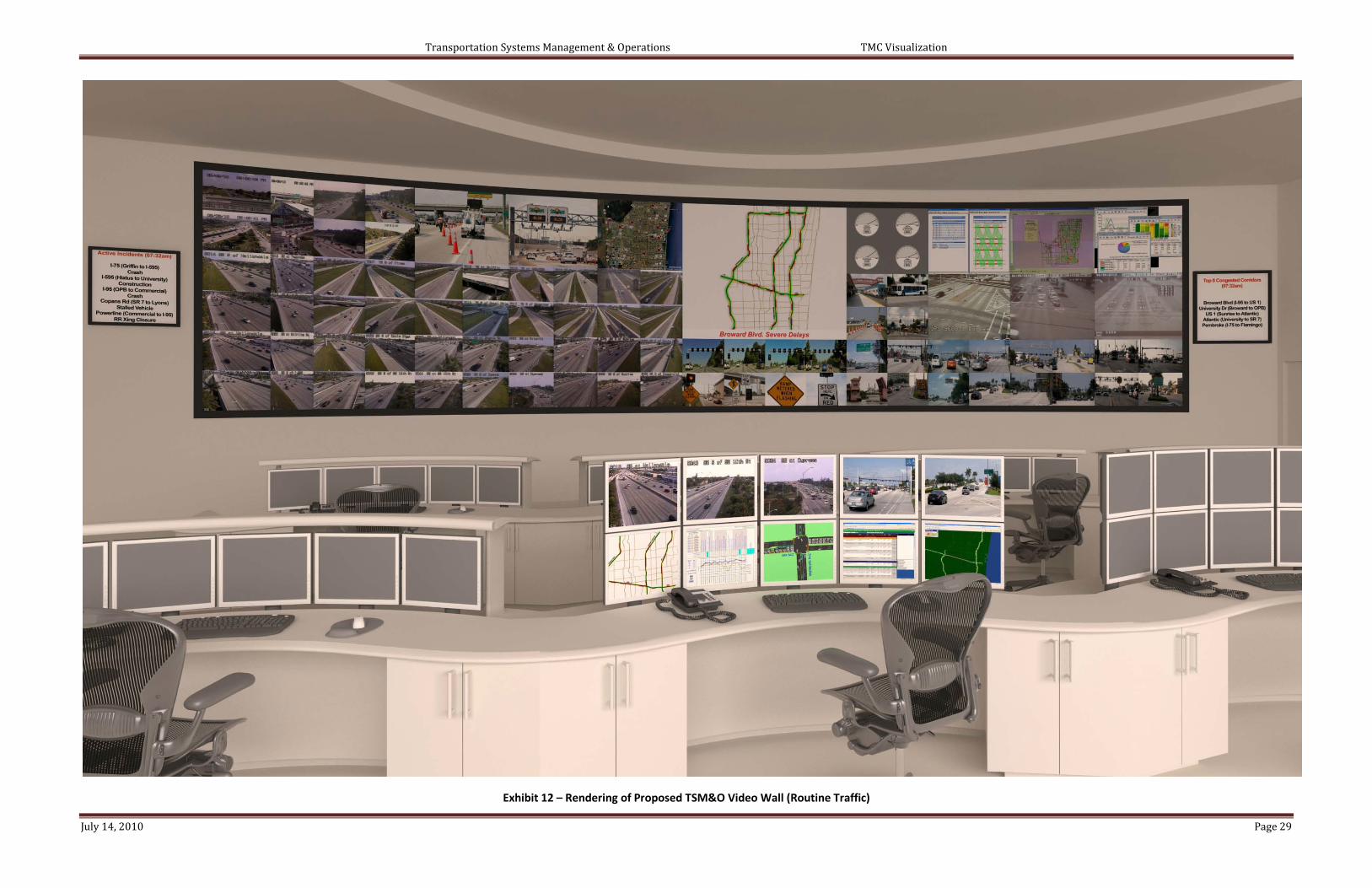
The TSM&O program will place new demands on the TMC operations staff in providing more of a balance between proactive transportation management and incident management. Alternative operating strategies were developed to address the goals of the TSM&O program, including the following components: congestion management; express lanes operations; ramp metering operations; real-time signal timing optimization; active traffic management operations; TSM&O network monitoring; traffic engineering; monitoring performance measures; transit AVL monitoring; railroad and drawbridge crossing monitoring. Concepts of how the video wall should be used during routine (i.e., default mode), as well as an incident event, were developed to support the TSM&O program and are presented in Exhibits 10 and 11. Columns 1 -5 will be used for FDOT interstate operations; Columns 6 -8 for TSM&O operations; and Columns 9 – 11 for BCTED signal system operations. In addition, renderings are presented in Exhibits 12 and 13 illustrating the recommended changes to the video wall for “routine” and “incident event” traffic conditions. These concepts were based on the needs to support the TSM&O program goals as well as input received from FDOT District Four (Section 2.3) and BCTED operations staff (Section 2.4). The purpose of the large TSM&O Map in the center of the video wall, as well as on the workstations, is to provide “green, yellow and red” indications on how different parts of the freeway / arterial / transit network is performing in terms of selected performance measures.

Transportation Systems Management & Operations TMC Visualization
July 14, 2010 Page 28
TMC Video Wall Configuration
Exhibit 9 - Current TMC Video Wall Configuration
Exhibit 10 - Proposed TSM&O Video Wall Configuration (Routine Traffic)
Exhibit 11 - Proposed TSM&O Video Wall Configuration (Incident Event)
FDOT Interstate Monitoring Area
Broward TSM&O Monitoring Area BCTED Signal System Monitoring Area
ATM - Active Traffic Management RM - Ramp Monitoring AVL - Automated Vehicle Location
District 6 District 6 PBC PBC
District 6 District 6 PBC PBC
I-75 I-75 I-75 I-75 I-75 I-75 I-75 I-75
I-75 I-75 I-75 I-75 I-75 I-75 I-75 I-75
I-95 I-95 I-95 I-95 I-95 I-95 I-95 I-95 I-95 I-95 I-95 I-95 I-95 I-95
I-95 I-95 I-95 I-95 I-95 I-95 I-95 I-95 I-95 I-95 I-95 I-95 I-95 I-95
Commercial Blvd at NW 15th Avenue
Column 1 Column 2 Column 3 Column 4 Column 5 Column 6 Column 7 Column 11
BCTED Signal Communications Map
Commercial Blvd at NW 21st Avenue
Commercial Blvd at NW 21st Avenue
Commercial Blvd at Powerline Rd
Commercial Blvd at Powerline Rd
Column 10
Commercial Blvd at Powerline Rd
Commercial Blvd at Powerline Rd
Active Incident
Active Incident
Commercial Blvd at NW 15th Avenue
Active Incident
Column 8 Column 9
Commercial Blvd at NW 21st Avenue
Commercial Blvd at NW 21st Avenue
Commercial Blvd at NW 15th Avenue
Commercial Blvd at NW 15th Avenue
Active IncidentRow 1
Row 2
Row 3
District 6 District 6 PBC NC
District 6 District 6 PBC NC
I-95 95 I-75 I-75 I-75 I-75 I-75 I-75 I-75 I-75 AVL Feed #1 AVL Feed #2
I-95 I-95 I-95 I-95 I-95 I-95 I-95 I-95 I-95 I-95 ATM ATM ATM ATMRR Xing Feed #1
RR Xing Feed #2
Signal Retiming Feed #1
Signal Retiming Feed #2
Signal Retiming Feed
#3
Signal Retiming Feed
#4
Signal Retiming Feed #5
Signal Retiming Feed
#6
I-95 I-95 I-95 I-95 I-95 I-95 I-95 I-95 I-95 I-95 RM RM RM RMDrawbridge
Feed #1Drawbridge Feed #2
Roving CCTV Feed #1
Roving CCTV Feed #2
Roving CCTV Feed #3
Roving CCTV Feed #4
Roving CCTV Feed #5
Roving CCTV Feed #6
Active Incidents (7:32am) I-75 (Griffin to I-595)-Crash I-595 (Hiatus to Univ.)-Const. I-95 (OPB to Comm.)-Crash Copans Rd (SR 7 to Lyons)-Stalled Veh. Powerline (Comm. to I-95)-RR Xing Closure
I-75 I-75 I-75 I-75
TV News Weather
Performance Measures
Signal System Comm. Map
Signal System Communications
Report Screen Top 5 Congested Corridors (7:32am) Broward Blvd (I-95 to US-1) University Dr (Broward to OPB) US-1 (Sunrise to Atlantic) Atlantic (University to SR 7) Pembroke (I-75 to Flamingo)
Work Zone Feed #1
Work Zone Feed #2
Video Detection Mgt System Video Feed
#1Congested Roadway Segments… Congested Roa
Regional TSM&O Map
Signal System Software Statistical
Report Screen
Video Detection Mgt System Video Feed
#2
Video Detection Mgt System Video Feed
#3I-75I-95 I-95 I-75 I-75 I-75
Road Ranger Location Map
Express Lanes Toll Status
District 6 District 6 PB NC
District 6 District 6 PB NC
I-95 I-95 I-75 I-75 I-75 I-75 I-75 I-75 I-75 I-75 AVL Feed #1 AVL Feed #2
I-95 I-95 I-95 I-95 I-95 I-95 I-95 I-95 I-95 I-95 ATM ATM ATM ATMRR Xing Feed #1
RR Xing Feed #2
Incident Area VIDS or CCTV
# 1
Incident Area VIDS or
CCTV # 2
Incident Area VIDS or CCTV
# 2
Incident Area VIDS or CCTV
# 2
Incident Area VIDS or CCTV
# 2
Incident Area VIDS or CCTV
# 2
I-95 I-95 I-95 I-95 I-95 I-95 I-95 I-95 I-95 I-95 RM RM RM RMDrawbridge
Feed #1Drawbridge Feed #2
Roving CCTV Feed #1
Roving CCTV Feed #2
Roving CCTV Feed #3
Roving CCTV Feed #4
Roving CCTV Feed #5
Roving CCTV Feed #6
Active Incidents (7:32am) I-75 (Griffin to I-595)-Crash I-595 (Hiatus to Univ.)-Const. I-95 (OPB to Comm.)-Crash Copans Rd (SR 7 to Lyons)-Stalled Veh. Powerline (Comm. to I-95)-RR Xing Closure
I-95 I-95 I-75 I-75 I-75 I-75 I-75 I-75
Top 5 Congested Corridors (7:32am) Broward Blvd (I-95 to US-1) University Dr (Broward to OPB) US-1 (Sunrise to Atlantic) Atlantic (University to SR 7) Pembroke (I-75 to Flamingo)
Work Zone Feed #1
Work Zone Feed #2
Performance Measures
Signal System Software Statistical
Report Screen
Active Incidents…Active Incidents… Active
Video Det. Mgt. System Active
Incident Video Feed "A"
Signal System Comm. Map
Signal System Communications
Report Screen
Video Det. Mgt. System Active
Incident Video Feed "B"
Signal Software Real-Time Inters. Timing
Ops @ Active Incident
Upstream of Queue Active Incident
Active Incident - CCTV
Beginning of Queue
I-75 I-75
Transportation Systems Management & Operations TMC Visualization
July 14, 2010 Page 29
Exhibit 12 – Rendering of Proposed TSM&O Video Wall (Routine Traffic)

Transportation Systems Management & Operations TMC Visualization
July 14, 2010 Page 30
Exhibit 13 - Rendering of Proposed TSM&O Video Wall (Incident Event)

Transportation Systems Management & Operations TMC Visualization
July 14, 2010 Page 31
5.0 TSM&O STAFF JOB DESCRIPTION
A recommended job description for the TSM&O staff is presented in this section. This job description provides an overview of the TSM&O Specialist’s responsibilities within the SMART SunGuide TMC in accordance with the format included in the Standard Operating Guidelines.
Responsibilities The TSM&O Specialist will be responsible for traffic engineering support within the TMC. This position will be responsible for performing the following functions:
• Congestion Management • Express Lanes Operations • Ramp Metering Operations • Active Traffic Management Operations • TSM&O Network Monitoring • Traffic Engineering/Safety • Real-time Signal Timing Changes • Performance Measures Monitoring • Transit AVL Monitoring • Railroad Crossing Monitoring • Drawbridge Crossing Monitoring
The TSM&O Specialist will provide on-site support within the control room for both FDOT and BCTED in performing traffic operations in real-time. Knowledge, Skills, Abilities The desired “Knowledge, Skills and Abilities” of the TSM&O Specialist is listed below:
• B.S. Degree in Engineering*; M.S. Degree in Transportation • Minimum 5 years experience in traffic engineering, and/or ITS* • Micro-simulation traffic modeling experience (i.e., HCS, Synchro, SimTraffic)* • Traffic safety and operations study experience* • Signal timing experience* • Maintenance of Traffic experience* • Transit planning and operations experience
While it is recognized that the TSM&O Specialist may not have qualifications in all of the above areas, the ones marked by an asterisk are mandatory while the others are desired.
Supervision
The TSM&O Specialist reports to the FDOT District 4 TSM&O Manager.

Transportation Systems Management & Operations TMC Visualization
July 14, 2010 Page 32
6.0 SUMMARY
In summary, the recommendations provided in this technical memorandum should be considered in reconfiguring the control room of the SMART SunGuide TMC to support the functional requirements of the TSM&O program. These recommendations should be reviewed and adopted by the primary stakeholder agencies (i.e., FDOT, BCTED, BCT) to ensure that modifications to the video wall and workstations will contribute to making informed decisions in a more efficient manner considering the TSM&O network of freeways, arterials and transit systems. Furthermore, the TMC reconfiguration recommendations should be integrated into the “TSM&O Concept of Operations” and support the strategies presented in the “2015 Update of the FDOT District 4 ITS Strategic Business Plan”.

Transportation Systems Management & Operations TMC Visualization
July 14, 2010 Page 33
Appendix A – TMC Survey

Transportation Systems Management & Operations TMC Visualization
July 14, 2010 Page 34
TMC Surveys

Transportation Systems Management & Operations TMC Visualization
July 14, 2010 Page 35

Transportation Systems Management & Operations TMC Visualization
July 14, 2010 Page 36

Transportation Systems Management & Operations TMC Visualization
July 14, 2010 Page 37
Appendix B – Summary of TMC Surveys
Transportation Systems Management & Operations TMC Visualization
July 14, 2010 Page 38
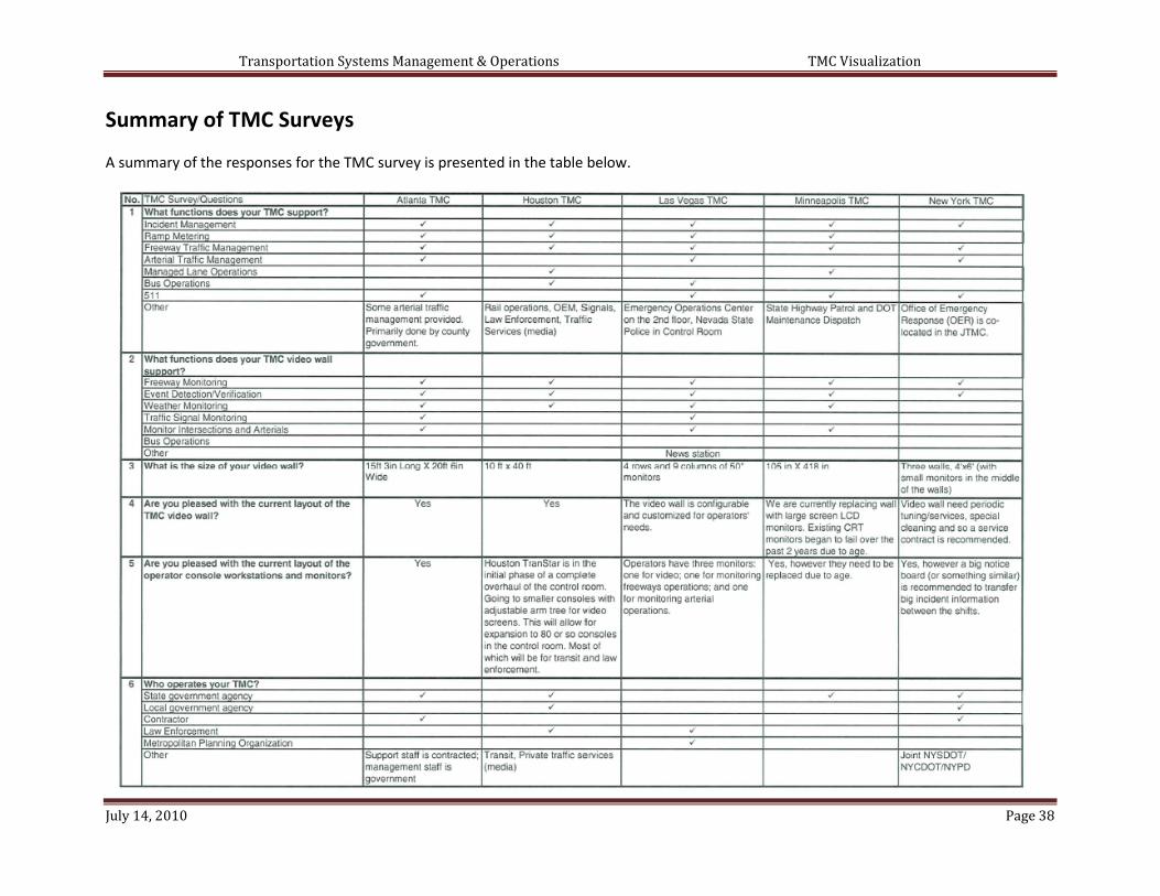
Summary of TMC Surveys
A summary of the responses for the TMC survey is presented in the table below.

Transportation Systems Management & Operations TMC Visualization
July 14, 2010 Page 39

Transportation Systems Management & Operations TMC Visualization
July 14, 2010 Page 40

Transportation Systems Management & Operations TMC Visualization
July 14, 2010 Page 41
Appendix C – TMC Interviews

Transportation Systems Management & Operations TMC Visualization
July 14, 2010 Page 42
TMC Interviews
A summary of the follow-up telephone interviews with each TMC is presented in the following pages. The purpose of these follow-up calls was to provide more details on specific survey questions.
Georgia Navigator TMC (Atlanta, Georgia)
Q1: What functions does you TMC support?
• GDOT is responsible for incident management across the state. There are several other centers within local jurisdictions that manage the arterials. These other centers utilize the same platform so the Georgia Navigator TMC can manage the arterials, if necessary. Although GDOT has the capability to manage local roads, the local jurisdictions have primary control. The Georgia Navigator TMC operates the CCTV cameras, DMS, vehicle detection systems and ramp meters located within the metropolitan region. Although the system is statewide, approximately 80% of the ITS devices are located within metropolitan Atlanta.
• Signal timing is provided by local jurisdictions. Traffic signals are being integrated in the new GDOT software. It will provide staff with the capability to monitor and update signal timing, if needed. If there is an outage, the TMC is typically advised of the problem and they redirect the issue to the appropriate jurisdiction.
Q7: How is your TMC staffed?
• Traffic engineering staff is present within the TMC on day shifts. These traffic engineers understand traffic modeling techniques and traffic flow principles, thereby addressing traffic problems at a higher level. For example, traffic engineers understand operation of the 140+ ramp meters, which is helpful when calls come in or issues arise. They can also observe traffic conditions based on time-of-day, and historical data, thereby being able to make educated decisions on how to divert traffic and display alternate route information, if needed. One traffic engineer is assigned per shift.
• The TMC collects a significant amount of data to support performance measurement. The TMC software provides a comprehensive system that generates information based on location. This data is used to support decisions regarding future ITS deployments, incidents, travel times, construction, transfers to other modes (e.g. transit), etc.
• Police reports are captured in a different system by a different work unit (i.e., not the TMC). The
TMC collects information on crashes / incidents on all state roads. The TMC also has maintained working relationships with other emergency response agencies, including the emergency operations centers / 911 dispatch centers.
• Highway Emergency Response Operators (service patrols) are state employees, not contracted
employees. HERO staff is required to participate in an extensive training program. • Data is being collected to build an intelligent system and used as a means to be proactive. For
example, DMSs have been deployed upstream of high crash / incident locations to advise motorists to slow down. Another example pertains to ramp meters that have resulted in

Transportation Systems Management & Operations TMC Visualization
July 14, 2010 Page 43
congestion along arterials feeding into the interstate highway. GDOT is actively working on signal timing systems to alleviate this congestion yet still use ramp metering to ease congestion along the highway.
Q10: Strategies to maximize traffic capacity?
• Variable speed limits and ramp metering systems are being utilized to optimize traffic capacity. “Hard-shoulder running” is not being applied, however it is being considered for future applications.
• Travel times are posted on DMSs. They are considering posting weather conditions on DMSs.
Q11: Who operates the traffic signal system?
• GDOT has capability, but it is primary the responsibility of the local governments.
Q13: Integrated Transportation Management System?
• Existing software was developed in preparation for the 1996 Summer Olympics. Many of the ITS devices needed to be integrated into the legacy system.
• The new software system is off-the-shelf. It has enhanced capability, more features/functions; and is more user-friendly for operators. GDOT will not need to enter an extensive amount of information in the comment section – the software provides drop -down menus/buttons.
• Transit systems have their own operations center. The only other offices within the TMC belong
to contractors performing work for the state.
Closing Comments
• GDOT highly recommends conducting site visits before reconfiguring the video wall layout and workstations. This effort should support a vision what it is going to look like 3-5 years in the future.

Transportation Systems Management & Operations TMC Visualization
July 14, 2010 Page 44
FAST TMC (Las Vegas, Nevada)
Functions supported by the TMC
• The Regional Transportation Commission (RTC) serves as the MPO; provides traffic operations for both freeways and arterials; and manages transportation funding. However, they are not responsible for traffic signal design. Upon signal activation, the RTC becomes involved including signal timing coordination (they do not modify clearance intervals or adjust timing). Signal timing decisions are made by experienced technicians based on observations rather than solely on traffic modeling simulations. RTC uses lead / lag sequencing, left turn signaling. Local entities have traffic engineers and technicians to perform signal timing but not coordination. If there is an issue with detection, the RTC will notify the local jurisdiction to take action.
• RTC performs controller maintenance and works directly with the vendor of signal software.
Their primary focus is on coordination. • Local jurisdictions provide vehicle detection. RTC is responsible for coordination and
communication using their field technicians. • RTC provides signal timing response to video monitoring. However, CCTV camera coverage along
arterials is not as extensive as the freeway system. The arterial system is a grid network; therefore, altering east / west green times would impact north / south movements, and vice versa. Therefore, signal timing adjustments are made on a very limited basis. The TMC staff, as well as field technicians, can change signal timing coordination. The TMC and field technicians collaborate via phone. For the most part, signal timing coordination changes provided by the TMC staff are based on information from the field technicians.
• RTC has CCTV cameras along arterials; however, denser CCTV camera coverage is provided along
freeways. CCTV cameras along arterials are occasionally used, but it is more likely that a field technician will go to the field to observe the situation. Many CCTV cameras were installed 10-15 years ago. RTC is currently in the process of adding more arterial cameras. Approximately 200 CCTV cameras are needed to provide adequate coverage of major intersections; however, only 40-50 CCTV cameras exist today.
• RTC provides live streaming video on their website, including arterial coverage. • RTC can use CCTV cameras to provide proactive traffic management to accommodate local
jurisdictions (e.g., pre-planned major events). • Maintenance of signal cabinets is typically performed by local jurisdictions. Controller
maintenance is paid for by RTC. RTC does not own the signal system – just provides a service. • RTC recently improved Bus Rapid Transit service by applying Transit Signal Priority. No one from
transit is located at the TMC; however, video feeds are made available for transit operations. RTC has maintained a good relationship with transit.

Transportation Systems Management & Operations TMC Visualization
July 14, 2010 Page 45
Functions of the Video Wall
• One of the cells on the wall displays the weather map and wind speed. This is useful particularly as some highways traverse mountain passes. The TMC can use outlying DMSs to post messages. Another cell is used for television, typically a news station. This useful as there is more than one agency in the building.
• Although news stations do not sit within the control room, they do have access to video. They can switch views of the CCTV cameras. The RTC logo is used on the CCTV camera feeds that are shown on television, which are used extensively. Mostly freeway cameras are used as that is where the most incidents occur. CCTV camera images can be suppressed if needed (i.e., when operators zoom in to monitor an incident).
Operations at the TMC
• The workstations have three monitors (i.e., freeway operations, arterial operations, CCTV camera).
• Law enforcement has limited access to posting messages.
Strategies to maximize traffic capacity
• Ramp metering decisions that impact adjacent signals are managed by TMC operations staff.
Operation of the Traffic Signal System
• Local jurisdictions do not work within the TMC. All operations staff work for the RTC, except the Nevada Highway Patrol staff.
Micro-simulation Modeling
• Traffic simulation modeling is not performed by the RTC staff.
• Signal timing coordination address time of day plans (sometimes as early as 4 a.m.) and different peak periods. Typically, all signals change at the same time of day. Special timing plans for traffic detours to arterials, due to an incident, have been considered but have not been implemented as historically travelers do not divert - they tend to stay on the freeway. Using CCTV cameras, freeway ramp signaling can be adjusted. Arterials do not have sufficient capacity to absorb all freeway traffic.
• Prior to 2004, local jurisdictions provided funding for managing signalized intersections along arterials. Subsequently, the arterial network operation was assigned to the RTC and is funded through local tax dollars.

Transportation Systems Management & Operations TMC Visualization
July 14, 2010 Page 46
• Signal prioritization exists within a few limited corridors. • RTC applies the following signal operations techniques for transit: queue-jumping; transit signal
priority; and other operating strategies upon request by the transit agency. • Nevada Highway Patrol (NHP) can request to move CCTV cameras to support their operations.
RTC works very close with NHP. There is a good working relationship with technicians, dispatchers and management. RTC and NHP are each assigned ten workstations.
• RTC provides live video feeds to the media, NDOT and local jurisdictions. Provision of video feeds
to local police departments, fire stations and other responders are being considered.

Transportation Systems Management & Operations TMC Visualization
July 14, 2010 Page 47
Houston TranStar (Houston, Texas)
Q1: What functions does your TMC support?
• The TMC is a multi-agency operation. Light-rail operations are managed from the TMC. There is a single light rail line, with expansion planned for two additional lines. Real-time monitoring and operations are performed from the TMC by operators and supervisors. There is only one point where the rail line runs under the freeway and affects frontage roads. If there is a conflict at this point, which is rare, there is coordination between the rail and freeway management agencies. There are no at-grade crossings along the highways. Frontage roads are prevalent throughout Houston and they operate as typical arterial streets.
• The Harris County Emergency Management Agency is located within the facility. The City of Houston used to operate from this facility; however, they relocated to their own facility.
• Private traffic information providers (e.g. Metro Traffic, Traffic.com) are located at the TMC. They
collect traffic information and disseminate it via radio and television. TV stations have contracts with TxDOT to display images.
Q2: What functions does your TMC video wall support?
• There are two types of weather monitoring systems at the TMC. One belongs to Harris County weather services. They measure rainfall and creek levels to monitor flooding.
• Although weather monitoring, or any weather website (e.g. WeatherTab), can be posted on the video wall, this is not done as the same information is available at the consoles. Every operator has the capability to display information to the video wall.
• The video wall includes four rear-projection Barco cubes.
Q5: Operator consoles?
• They are changing to flat screen on arm-trees so they are adjustable.
• They currently have approximately 36 consoles in the control room. They have already eliminated the viewing room and five offices in the back of the control room to add more space. They are also removing the video wall to add more consoles. The final configuration will include 80 smaller consoles. This will create more room for agency operations staff such as transit and law enforcement.
Q6: Who operates the TMC?
• Transit operations were moved to the TMC so they could take advantage of the traffic information available. They also piggy-backed on the fiber optic communications system to interface with security cameras located at parking structures.

Transportation Systems Management & Operations TMC Visualization
July 14, 2010 Page 48
• None of the agencies pay rent for use of the control room. Agencies requiring office space do contribute to the rent.
• Many commuter buses use the HOV lanes. • Primary agencies operating within control room include Texas DOT and Metro (transit). County
and City police are also located within the control room; however, their primary function is to dispatch and manage the Safe Clear program to clear lanes along freeways. The Police can authorize a wrecker to remove a stalled vehicle from the road without being present on the scene. This program has been in place for about five years. They also implement the Mobility Response Team (MRT) which is civilians that work with the Police Department to help operate traffic control.
Q7: How is the TMC staffed?
• Engineering staff performs modeling and develops contingency plans for events. Different agencies (i.e., state, county, and city) have engineers located at the TMC performing their respective duties. They are present on a daily basis and collaborate as needed. Most of the managers are engineers.
• There are five traffic engineers from Texas DOT on site performing different duties such as operations and maintenance.
• Harris County and the City of Houston have a number of their signal technicians and operators
located within the facility. Texas DOT signal operations are located at a nearby building.
Q10: Strategies to maximize traffic capacity?
• Shoulders are used for hurricane evacuation (monitored from the TMC). In the future, shoulders will possibly be used for buses to access the HOV lanes faster. FHWA has also given permission to use shoulders in designated areas as additional lanes (e.g. during heavy congestion); however, the use must be monitored.
Q11: Who operates the traffic signal system?
• Texas DOT signal technicians report to different supervisors in different areas. The TMC dispatches the signal technicians.
• TMC operators can use the CCTV cameras to monitor signal problems and repair. However, many signals are located within remote locations where CCTV camera monitoring is not available. In remote locations, cities are paid to maintain state signals.
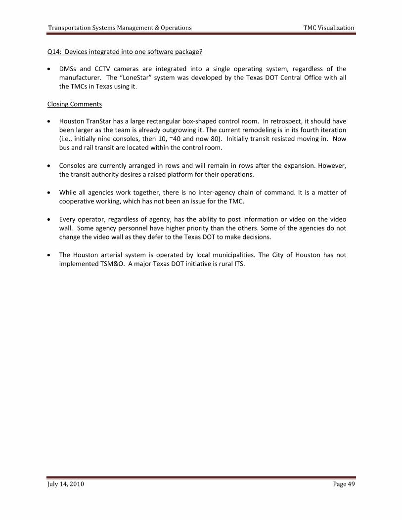
Transportation Systems Management & Operations TMC Visualization
July 14, 2010 Page 49
Q14: Devices integrated into one software package?
• DMSs and CCTV cameras are integrated into a single operating system, regardless of the manufacturer. The “LoneStar” system was developed by the Texas DOT Central Office with all the TMCs in Texas using it.
Closing Comments
• Houston TranStar has a large rectangular box-shaped control room. In retrospect, it should have been larger as the team is already outgrowing it. The current remodeling is in its fourth iteration (i.e., initially nine consoles, then 10, ~40 and now 80). Initially transit resisted moving in. Now bus and rail transit are located within the control room.
• Consoles are currently arranged in rows and will remain in rows after the expansion. However, the transit authority desires a raised platform for their operations.
• While all agencies work together, there is no inter-agency chain of command. It is a matter of
cooperative working, which has not been an issue for the TMC. • Every operator, regardless of agency, has the ability to post information or video on the video
wall. Some agency personnel have higher priority than the others. Some of the agencies do not change the video wall as they defer to the Texas DOT to make decisions.
• The Houston arterial system is operated by local municipalities. The City of Houston has not
implemented TSM&O. A major Texas DOT initiative is rural ITS.

Transportation Systems Management & Operations TMC Visualization
July 14, 2010 Page 50
GuideStar TMC (Minneapolis, Minnesota)
Q1: What functions does your TMC support?
• Freeway service patrols are dispatched by staff at the TMC. Longer-term maintenance (i.e., snow removal, pot-hole fill) is managed by the DOT maintenance dispatch, who are there 24-hours per day as is the highway patrol dispatch. The TMC is not a 24-hour per day operation. Arterial monitoring is occasional. All groups have access to the CCTV cameras at their desks.
• Highway patrol dispatchers are in uniform and management has offices. Statewide 911 is located within the building, but not on the control room floor. There are sworn officers present, but not gun-carrying. The dispatchers confirm location, direction and scope of the incident based on the CCTV cameras.
• The TMC goal is to detect and post the CCTV camera on the video wall as soon as possible so that
others within the room can view what is happening. Most incident detection is derived from 911 calls and service patrols. Cellular 911 calls go to the highway patrol within the building. Land line calls go to city or county call centers. Sometimes that information is not immediately passed on to the highway patrol which causes a delay in response time. There are a decreasing number of calls coming into the TMC. They try to listen to police scanners at the TMC to pick up additional local activity.
• The TMC has a traffic flow map posted on the video wall where the operations staff observe if
something is unusual. The TMC operators must be knowledgeable on what is usual and have time to notice so they can detect conditions in that manner. They anticipate having automated notification in the future. Although there is a possibility that they can develop this in-house, they have limited programmer resources.
• Arterial operations by the state are in the development stages. In the past, maintenance was
based on complaints resulting in field visits. Now they have a desk within the TMC and they are installing CCTV cameras and initiating other mechanisms to monitor signals. There is also city and county operated signals, but those operations are not a part of the TMC. The TMC is attempting to implement integrated corridor management.
• They are currently working with a consultant to develop integrated corridor management along a
few corridors. This program would involve state, county and city signals and coordinating them for management of traffic during incidents. The project is in need of federal dollars to implement; however, they were not selected for the Integrated Corridor Management demonstration program and they are seeking other funds to implement the project.
• If an incident occurs along the freeway, the Minnesota DOT tries not to detour traffic to local
arterials. They attempt to divert highway traffic to other highways when at all possible. One problem is that some of the cities have smaller TMCs, but they have limited hours of operation. If there is a large incident, responders will attempt to divert traffic to the nearest roadway, then it is up to the maintenance supervisor when they arrive on scene to decide if they want to detour traffic freeway to freeway, even if they have to push back the closure. They have a good system of detouring because of their ring road system; however, most are operating at capacity.

Transportation Systems Management & Operations TMC Visualization
July 14, 2010 Page 51
• Most arterials are managed by local agencies. There is little interaction with the responders. In some cases, they have contacted the TMC to add information to traveler information. The TMC has no CCTV cameras along arterials, so there is no way to monitor the progress of the incident.
Q2: What functions does your TMC video wall support?
• The video wall is located in front of the TMC group. The DOT maintenance and highway patrol have mini-walls consisting of 12 computer monitors. During incidents, the incident is posted on the monitors and repeated throughout the room, and then the operator can look up and also see it on the video wall.
• Controlling the video wall is shared among all agencies within the control room. If someone needs to view something before their turn, they simply ask. There have been attempts to develop a formal policy regarding shared control but there is a basic understanding in sharing control as needed. CCTV cameras are visible by the media and public, so all staff knows that zooming in on something is not appropriate.
• They recently rebuilt the video wall because the original CRTs were beginning to fail. They were
replaced by LCDs split into four quadrants. The video wall size is 105” high x 418” wide (i.e., 3 LCDs high by 7 LCDs wide). Maintenance mini-walls are 38” high by 193” wide. They consist of 3 LCDs – two are for incidents, one is for weather radar.
Q7: How is your TMC staffed?
• A Principal Engineer manages the freeway patrol and incident management program. They also utilize graduate engineers that sometimes work a 6-month period at the TMC as part of the DOT program.
Q8: Is your TMC equipped to collect data?
• Performance measures are collected only for freeways as they are the only system instrumented.
Q9: Do you share your video images with other agencies?
• They share images with TV stations, transit and local PSAPs. The primary transit agency has a large dispatch center within the metro area. They have CCTV camera feeds and occasionally call to help locate a stranded bus. If the TMC detects a stranded bus or incident that will impact the route, they will call the transit center. They use a log-in program to view streaming images.
Q10: Strategies to maximize traffic capacity?
• They are beginning to use shoulders during peak periods. This helps traffic move up to 15 miles per hour faster. It is also part of the managed lanes program – priced dynamic shoulder lane.

Transportation Systems Management & Operations TMC Visualization
July 14, 2010 Page 52
Variable speed limits are coming on-line within a few months. It would be an advisory speed – not enforceable. Lane control signals are used for the priced dynamic shoulder lanes and other applications. There is a fairly aggressive deployment program of lane control signals.
Q12: Micro-simulation Modeling?
• They do not use real-time modeling. They prefer to keep motorists on the freeway as much as possible and minimize “active” detouring. Some motorists will detour themselves if they know the area roads. The TMC does not actively detour, mainly because they do not know the condition of the arterials they are detouring to.
Q14: Devices currently integrated into one software package?
• The name of the program they use is Iris. The TMC will need to have different software to manage arterials. Iris is open-source, so if arterial management software was open source they could possibly integrate the two software systems.
Q15: TMC reconfiguration?
• The current TMC configuration is flexible and they already have a desk set up for arterials. The arterial desk has its own small video wall. There are also extra desks available in the freeway operations section which could be used, if needed.
Closing Comments
• Approximately eight years ago, there were some issues with different agencies working together simply because of a lack of understanding of each other’s responsibilities. Addressing these differences up front can improve collaboration.

Transportation Systems Management & Operations TMC Visualization
July 14, 2010 Page 53
Joint Traffic Management Center (New York City, New York)
• The JTMC accommodates personnel from New York State DOT (NYSDOT), New York City DOT (NYCDOT), New York Police Department (NYPD) and Office of Emergency Management. The first row is used by NYSDOT, second row by NYCDOT, and the third row by NYPD.
• The JTMC has three video walls with small monitors in the middle of three walls. Any of the above agencies may use these three video walls.
• All work stations have the same capabilities; however, NYPD cannot post messages on DMSs.
Messages on DMSs are coordinated between NYSDOT and NYCDOT. • The JTMC does not support transit operations. They have their own control center for transit
operations/management. • There are approximately 500 cameras (i.e., 250 by NYSDOT and 250 by NYCDOT). • The NYCDOT is primarily responsible for operating and maintaining the traffic signal system. The
JTMC supports Arterial Management activities. TMC operators can modify signal timing in response to congestion, queuing related to incidents, etc. and can activate arterial DMSs.
• Operators have the ability to display color traffic flow maps (based on speeds) on work stations. • Scrolling video images of congested (recurring) locations or hot spots and traffic flow maps are
normally posted on video walls during routine operation (non-incidents). • Traffic flow maps, service patrols (only on freeways) and NYPD are the primary sources for
incident identification and then verified with CCTV cameras. • The JTMC uses EZ Pass readers to generate travel times. Travel time information is posted on the
511 website - 511NY.ORG. • Each work station has three monitors. • The NYSDOT and NYCDOT traffic engineering staff is present within the TMC. They use TMC data
for planning event activities, monitoring performance measures and planning/coordinating construction activities. They use DMSs to post messages related to construction activities.
• The JTMC collects and uses volume, speed and occupancy data for ATMS systems. • The JTMC shares video images with TRANSCOM, 511NY, local TV, NYSDOT Main office (Albany)
via a T-1 line. These agencies/offices can only observe images (i.e., they do not have the ability to control images).

Transportation Systems Management & Operations TMC Visualization
July 14, 2010 Page 54
• TRANSCOM, a regional transportation organization, consists of 16 different agencies from three states - Connecticut, New York and New Jersey. Center-to-Center communications among these agencies is in place and they coordinate traffic management activities for major activities/events.
• NYSDOT is planning to implement variable speed limits along their freeways. • Managed and reversible lane operations are in place along their expressways. • NYSDOT is developing a system for automatic detection and notification of congested and
incident locations.