technical report 8 - assessment of lighting effects · technical report 8 – assessment of...
TRANSCRIPT
Technical Report 8
Assessment of Lighting Effects Prepared By Beca Carter Hollings and Ferner Limited
17 February 2012

Technical Report 8 – Assessment of Lighting 10 April 2012 // Page (i)
Revision History
Revision Nº Prepared By Description Date
A Keith Gibson Draft Issue 5 July 2011
B Keith Gibson Revised 17 Nov. 2011
C Keith Gibson Chapman Tripps comments added 12 Feb. 2012
D Keith Gibson Note relating to drawings added 17 Feb. 2012
Document Acceptance
Action Name Signed Date
Prepared by Keith Gibson
17 Feb. 2012
Reviewed by Peter Taylor
17 Feb. 2012
Approved by John Goodwin
17 Feb. 2012
on behalf of Beca Carter Hollings and Ferner Limited
Technical Report 8 – Assessment of Lighting 10 April 2012 // Page (i)
Table of Contents
1. Assessment of Lighting Effects Report ........................................................... 1
1.1. Introduction .................................................................................................................. 1
1.2. Report Structure ........................................................................................................... 1
1.3. Project Description ....................................................................................................... 2
2. Schedule of Standards and District Plan Criteria ............................................. 4
2.1. Lighting Standards ....................................................................................................... 4
2.2. Kāpiti Coast District Plan ............................................................................................. 4
2.3. AS/NZS 1158 Part 0 and 1.1 - Road Lighting .............................................................. 6
2.4. AS/NZS 1158 Part 3 - Pedestrian Lighting .................................................................. 7
2.5. AS 4282:1997 – Control of the Obtrusive Effects of Outdoor Lighting ........................ 7
3. Assessment Matters ......................................................................................... 8
3.1. Potential Adverse Effects ............................................................................................. 8
3.2. Spill Lighting ................................................................................................................. 8
3.3. Glare ............................................................................................................................ 9
3.4. Skyglow Effect ............................................................................................................ 10
3.5. Construction Activity................................................................................................... 10
3.6. Headlight Sweep ........................................................................................................ 11
4. Lighting Infrastructure ................................................................................... 12
4.1. Types of Luminaires ................................................................................................... 12
4.2. White Light/Golden White Light ................................................................................. 12
4.3. Road Lighting ............................................................................................................. 13
4.4. Road Bridge Lighting.................................................................................................. 13
4.5. Flag Lighting ............................................................................................................... 14
4.6. Cycleway/walkway Way Lighting ............................................................................... 14
4.7. Lighting Pole Arrangements ....................................................................................... 15
4.8. Height of Poles ........................................................................................................... 15
4.9. Signage ...................................................................................................................... 15
5. Proposed Lighting .......................................................................................... 16
5.1. General ...................................................................................................................... 16
Technical Report 8 – Assessment of Lighting 10 April 2012 // Page (ii)
6. Proposed Lighting in Sector 1 ........................................................................ 16
6.1. Start of the Expressway to the Poplar Avenue Interchange ...................................... 16
6.2. Poplar Avenue Interchange ....................................................................................... 17
6.3. Existing Environment ................................................................................................. 19
6.4. Assessment of Lighting Effects .................................................................................. 19
6.5. Recommended Mitigation Measures ......................................................................... 19
7. Proposed Lighting in Sector 2 ........................................................................ 20
7.1. Poplar Avenue Interchange to Kāpiti Road Interchange............................................ 20
7.2. Raumati Road Over Bridge Section ........................................................................... 20
7.3. Cycleway/walkway Lighting ....................................................................................... 20
7.4. Kāpiti Road Interchange ............................................................................................ 21
7.5. Mazengarb Road Over Bridge Section ...................................................................... 22
7.6. Existing Environment ................................................................................................. 23
7.7. Assessment of Lighting Effects .................................................................................. 23
7.8. Recommended Mitigation Effects .............................................................................. 25
8. Proposed Lighting in Sector 3 ........................................................................ 26
8.1. Mazengarb Road to Te Moana Interchange .............................................................. 26
8.2. Te Moana Expressway ............................................................................................. 26
8.3. Existing Environment ................................................................................................. 28
8.4. Assessment of Lighting Effects .................................................................................. 28
8.5. Recommended Mitigation Measures ......................................................................... 28
9. Proposed Lighting in Sector 4 ........................................................................ 28
9.1. Te Moana Interchange to Peka Peka Interchange .................................................... 28
9.2. Peka Peka Road Interchange .................................................................................... 29
9.3. Existing Environment ................................................................................................. 30
10. Assessment of Lighting Effects ..................................................................... 30
10.1. Peka Peka Road Connection ..................................................................................... 30
10.2. Recommended Mitigation Measures ......................................................................... 30
11. Report Summary............................................................................................. 30
11.1. Conclusion ................................................................................................................. 30
Technical Report 8 – Assessment of Lighting 10 April 2012 // Page (iii)
APPENDICES
APPENDIX 8.A AS/NZS 1158.1.1 TABLE 2.1 - CATEGORY V LIGHTING AND TYPICAL APPLICATIONS
APPENDIX 8.B AS/NZS 1158.3.1 TABLE 2.2 - LIGHTING CATEGORIES FOR PATHWAYS (INCLUDING CYCLEWAY/WALKWAY WAYS)
APPENDIX 8.C LUMINAIRE DESCRIPTION SCHEDULE
APPENDIX 8.D TABLE 2.1 - RECOMMENDED MAXIMUM VALUES OF LIGHT TECHNICAL PARAMETERS FOR THE CONTROL OF OBTRUSIVE LIGHT
APPENDIX 8.E DIAGRAMS DEMONSTRATING THE LUMINAIRE CUT-OFF CHARACTERISTICS.
APPENDIX 8.F LUMINAIRE BACK SPILL LIGHT CALCULATIONS
Technical Report 8 – Assessment of Lighting Effects 10 April 2012 // Page 1
1. Assessment of Lighting Effects Report
1.1. Introduction
The author has been engaged by the NZTA to prepare an assessment of effects of the lighting being proposed for the MacKays to Peka Peka project (the Project). This Report presents the findings of the assessment of lighting effects conducted as part of the environmental assessment of the Project.
The purpose of this Report is to evaluate the potential effects from the proposed lighting that will be installed on the Expressway, including the on/off ramp, interchanges, cycleway/walkways and construction activities.
Lighting can be viewed from two perspectives. First, ensuring that the proposed Expressway is safely lit for the users, and secondly managing the effects of that lighting on the surrounding environment. The lighting of motorways and roads conform to different lighting standards than those applicable to pedestrian and cycle ways, with different lighting standards again for the construction yard temporary lighting. These different types of lighting have been separated within the report for clarity.
Additional comment has been made on the potential effect of vehicle headlights using the proposed Expressway.
The areas addressed by the report are the after-dark effects such as spill lighting and glare and how these interact with the local body policies of obtrusive lighting.
This report is based on preliminary design concepts only and some of the finer technical details cannot be included until fully developed/final construction designs are in place. However, these final details will be in accordance with the Lighting Conditions.
1.2. Report Structure
This report is part of a suite of reports that have been prepared in support of the NoR and resource consent applications for the Project.
This report will cover:
¡ Expressway road lighting
¡ Road bridge structure uplighting
¡ On ramp/off ramp road lighting
¡ Cycleway/walkway lighting

Technical Report 8 – Assessment of Lighting Effects 10 April 2012 // Page 2
¡ Temporary construction yard lighting
Potential effects from lighting have been identified as a result of the Project and this Report has been prepared to assess these effects and comment on measures that can be implemented to avoid, remedy, or mitigate such effects.
In this Report, the following policies relating to exterior lighting have been referred to:
¡ Lighting Standards
¡ Kāpiti Coast District Plan requirements
1.3. Project Description
For the full Project description (construction and operation) refer to Part D, Chapters 6 and 7, Volume 2, of the AEE.
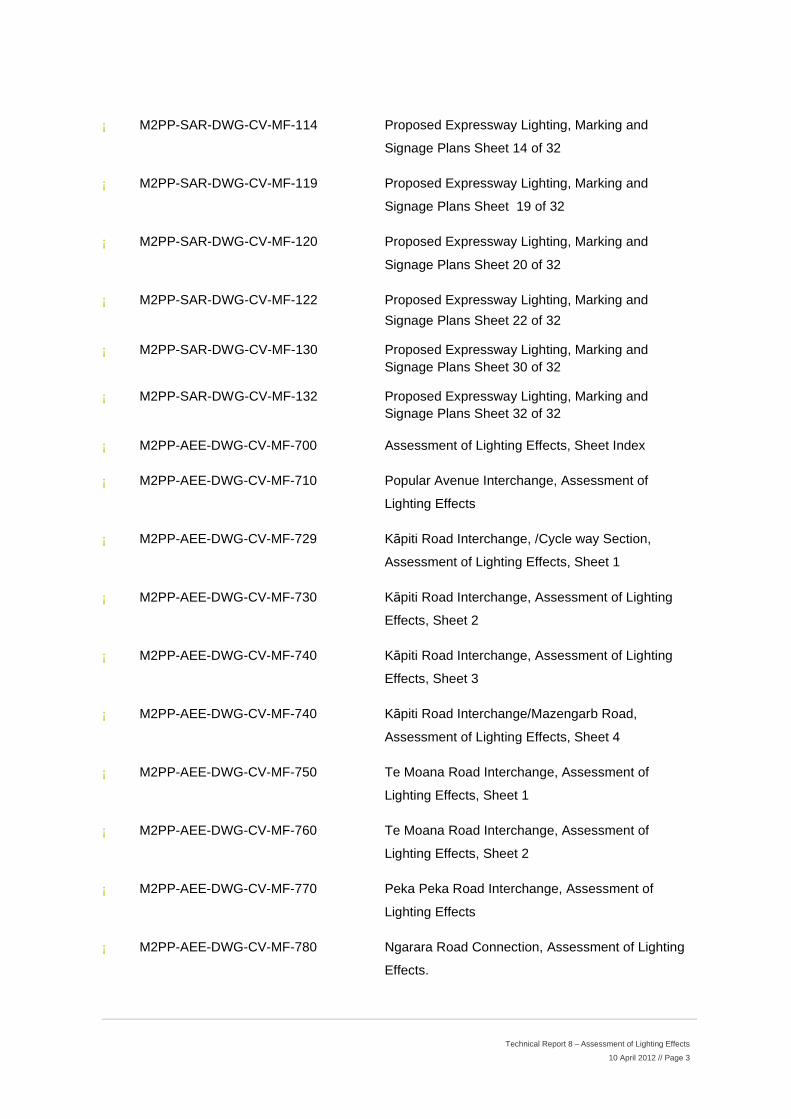
The following drawings are referenced in this report and detail the sections of Expressway where the proposed lighting will be installed (refer to Volume 5, Lighting for these drawings):
¡ M2PP-SAR-DWG-CV-MF-100 Proposed Expressway Lighting, Marking and Signage Plans Sheet Index
¡ M2PP-SAR-DWG-CV-MF-104 Proposed Expressway Lighting, Marking and Signage Plans Sheet 4 of 32
¡ M2PP-SAR-DWG-CV-MF-105 Proposed Expressway Lighting, Marking and Signage Plans Sheet 5 of 32
¡ M2PP-SAR-DWG-CV-MF-106 Proposed Expressway Lighting, Marking and Signage Plans Sheet 6 of 32
¡ M2PP-SAR-DWG-CV-MF-107 Proposed Expressway Lighting, Marking and Signage Plans Sheet 7 of 32
¡ M2PP-SAR-DWG-CV-MF-108 Proposed Expressway Lighting, Marking and Signage Plans Sheet 8 of 32
¡ M2PP-SAR-DWG-CV-MF-109 Proposed Expressway Lighting, Marking and Signage Plans Sheet 9 of 32
¡ M2PP-SAR-DWG-CV-MF-110 Proposed Expressway Lighting, Marking and Signage Plans Sheet 10 of 32
¡ M2PP-SAR-DWG-CV-MF-113 Proposed Expressway Lighting, Marking and Signage Plans Sheet 13 of 32
Technical Report 8 – Assessment of Lighting Effects 10 April 2012 // Page 3
¡ M2PP-SAR-DWG-CV-MF-114 Proposed Expressway Lighting, Marking and Signage Plans Sheet 14 of 32
¡ M2PP-SAR-DWG-CV-MF-119 Proposed Expressway Lighting, Marking and Signage Plans Sheet 19 of 32
¡ M2PP-SAR-DWG-CV-MF-120 Proposed Expressway Lighting, Marking and Signage Plans Sheet 20 of 32
¡ M2PP-SAR-DWG-CV-MF-122 Proposed Expressway Lighting, Marking and Signage Plans Sheet 22 of 32
¡ M2PP-SAR-DWG-CV-MF-130 Proposed Expressway Lighting, Marking and Signage Plans Sheet 30 of 32
¡ M2PP-SAR-DWG-CV-MF-132 Proposed Expressway Lighting, Marking and Signage Plans Sheet 32 of 32
¡ M2PP-AEE-DWG-CV-MF-700 Assessment of Lighting Effects, Sheet Index
¡ M2PP-AEE-DWG-CV-MF-710 Popular Avenue Interchange, Assessment of Lighting Effects
¡ M2PP-AEE-DWG-CV-MF-729 Kāpiti Road Interchange, /Cycle way Section, Assessment of Lighting Effects, Sheet 1
¡ M2PP-AEE-DWG-CV-MF-730 Kāpiti Road Interchange, Assessment of Lighting Effects, Sheet 2
¡ M2PP-AEE-DWG-CV-MF-740 Kāpiti Road Interchange, Assessment of Lighting Effects, Sheet 3
¡ M2PP-AEE-DWG-CV-MF-740 Kāpiti Road Interchange/Mazengarb Road, Assessment of Lighting Effects, Sheet 4
¡ M2PP-AEE-DWG-CV-MF-750 Te Moana Road Interchange, Assessment of Lighting Effects, Sheet 1
¡ M2PP-AEE-DWG-CV-MF-760 Te Moana Road Interchange, Assessment of Lighting Effects, Sheet 2
¡ M2PP-AEE-DWG-CV-MF-770 Peka Peka Road Interchange, Assessment of Lighting Effects
¡ M2PP-AEE-DWG-CV-MF-780 Ngarara Road Connection, Assessment of Lighting Effects.
Technical Report 8 – Assessment of Lighting Effects 10 April 2012 // Page 4
All sectors of the Project are located within the authority area of the Kāpiti Coast District Council and, at a regional level, the Greater Wellington Council area.
2. Schedule of Standards and District Plan Criteria
2.1. Lighting Standards
In this Report, the following Lighting Standards have been referred to:
¡ AS/NZS 1158.0:2005 Lighting for Roads and Public Spaces Part 0 - Introduction
¡ AS/NZS 1158.0:2005 Lighting for Roads and Public Spaces Part 1.1 - Vehicular Traffic (Category V) Lighting – Performance and Installation Design Requirements
¡ AS/NZS 1158.0:2005 Lighting for Roads and Public Spaces Part 3.1 - Pedestrian Area (Category P) Lighting – Performance and Installation Design Requirements
¡ AS 4282:1997 – Control of the Obtrusive Effects of Outdoor Lighting
The proposed Expressway and other classified road lighting design and cycleway/walkways, together with luminaire selection, proposed for the Project will conform to the requirements of Road Lighting Standard AS/NZS 1158.0:2005 series. This standard ensures safe vehicle and pedestrian movement and the timely identification of objects and pedestrians, to the motorist’s eye, while travelling at speed during the darkness hours.
Under the Road Lighting Standard, road lighting is divided into two types:
¡ Type V primarily for Vehicular movement; and
¡ Type P for Pedestrians movement
There are four categories of type V and twelve categories of type P within listed within AS/NZS 1158 series of Standards, ranging from non-arterial roads down to pedestrian footpaths and car parks. The Road Categories and their associated characteristics is detailed in Appendix 8.A. The appropriate category of cycleway/walkway lighting and its associated range of characteristics is detailed in Appendix 8.B.
2.2. Kāpiti Coast District Plan
As a designation, the Project is not required to comply with the District Plan. However, when preparing this Report, the District Plan requirements and the lighting standards that are referred to in the District Plan, have been considered as they provide a guide to appropriate lighting in the Project area.
Technical Report 8 – Assessment of Lighting Effects 10 April 2012 // Page 5
The NZTA is also required to comply with Section 153(3) of the Local Government Act 2002 which states that the Crown is bound by the bylaws if non-compliance by the Crown would be “likely to have an adverse effect on public health or safety”.
It is appropriate that both the proposed cycleway/walkway and temporary construction yard lighting conform to the District Plan standards as these provide lighting assessment criteria appropriate to the surrounding receiving environments.
The Kāpiti Coast District Plan details standards on lighting in the following zones:
D1 – Residential Zone Controlled Activity Standards
D2 – Rural Zone Controlled Activity Standards
D3 - Commercial Zone Controlled Activity Standards
D4 – Paraparaumu Town Centre Zone Controlled Activity Standards
D5 – Industrial/Service Zone Controlled Activity Standards
D6 – Open Space Zone Controlled Activity Standards
D7 – River Corridor Zone Controlled Activity Standards
D8 - Conservation Zone Controlled Activity Standards
D9 - Airport Zone Controlled Activity Standards
D10 – Lighting not relevant
D11 - Ngarara Controlled Activity Standards
Within these zones, street and road lighting is specifically exempted from the controls for the D1: Residential Zone, D9: Airport Zone, and D11: Ngarara Zone.
Within all the other zones, Kāpiti Coast District Council addresses the issue of obtrusive lighting within its District Plan by common requirements applicable for all zones in accordance with the following (typical) wording:
LIGHTING
Light level from the activity on site shall not exceed 10 lux, measured 1.5m inside the boundary of any adjoining rural or residential property. All buildings, other than temporary or accessory storage buildings, shall be provided with exterior lighting sufficient to illuminate main pedestrian areas.
The District Plan further clarifies requirements by the sub rule;
Technical Report 8 – Assessment of Lighting Effects 10 April 2012 // Page 6
LIGHT LEVELS
Between the hours of 10pm and 7am no artificial lighting may be used in such a manner that it causes:
¡ An added illuminance in excess of 10 lux measured horizontally or vertically at any window of any adjacent habitable building; or
¡ An added illuminance in excess of 20 lux measured horizontally or vertically at any point of any adjacent boundary of any adjacent land, which is zoned residential or used for a residential purpose.
¡ All exterior lighting is designed, installed and maintained to avoid the spill of light or glare which could create a traffic safety hazard on the state highway and local road network. Refer to “Australian Standard No. 4282 – 1997 Control of Obtrusive Effects of Outdoor Lighting.”
It should be noted that in the zones other than Residential, Airport and Ngarara zones, the wording again is slightly different depending on the zone purpose with the clear intent, shown by the common wording “All exterior lighting is designed, installed and maintained to avoid the spill of light or glare which could create a traffic safety hazard on the state highway and local road network” that the ‘exterior’ lighting being referred to is not road lighting, and therefore effects from road lighting are not necessarily relevant in these zones also.
It is appropriate that temporary construction yard lighting and the cycleway/walkway path lighting conforms to the relevant standards of the District Plan but not road lighting. To enable sensible assessment similar evaluation criteria has been applied to all lighting.
2.3. AS/NZS 1158 Part 0 and 1.1 - Road Lighting
Standard AS/NZS 1158 addresses both spill light and glare restraints (AS/NZS 1158.1.2 Section 7.3.3 and 7.3.4) and references the following issues:
¡ Upward light content.
¡ Sideways spill light content.
¡ Direct viewing of the luminaire (or lamp source).
¡ Colour of the light.
Within these sections, AS/NZS 1158 cross-references the AS 4282:1997 standard and explains that the spill lighting levels from road lighting is not considered high enough to be as obtrusive but glare from the road lantern may be of annoyance to adjacent residences and discusses mitigation measures such as shielding or the use of (light) cut-off luminaires.
Technical Report 8 – Assessment of Lighting Effects 10 April 2012 // Page 7
In terms of glare, AS/NZS 1158 only addresses the disability aspects of glare to the motorist and does not mention glare to any adjacent surroundings.
2.4. AS/NZS 1158 Part 3 - Pedestrian Lighting
A cycleway/walkway will be constructed adjacent to the proposed Expressway from Popular Avenue to the Peka Peka junction, but only the section between Raumati Road through to Mazengarb Road will be illuminated. Where the cycleway/walkway runs closely parallel to the proposed Expressway, the road lighting (where installed) will provide secondary illumination to the path.
The cycleway/walkway lighting level will be Category P4 as defined by AS/NZS 1158.
The appropriateness of the path lighting category is detailed in an extract from AS/NZS 1158, which is shown in Appendix 8.B.
2.5. AS 4282:1997 – Control of the Obtrusive Effects of Outdoor Lighting
The Australian Standard AS 4282:1997, “Control of the Obtrusive Effects of Outdoor Lighting” is referenced in the Kāpiti District Council District Plan as a method of assessing and addressing both spill light and glare. It should be noted that this Standard specifically excludes public road lighting and was originally intended for evaluating lighting of tennis courts (and similar areas) located within residential areas. The use of this standard is not appropriate for road lighting as the illumination levels are relatively low and the functionality of the lighting for safety of pedestrian and vehicular movement has a higher priority than sources of other potentially obtrusive light.
While the Australian AS 4282 Standard has been crossed referenced in the current Road Lighting Standard AS/NZS 1158 Road Lighting, it has not been adopted in New Zealand as there is controversy amongst professional illumination engineers over the technical content, which is thought to be too onerous and not specific enough for general use for all exterior lighting applications.
It does however, supply some means of comparison on what is acceptable and the ability to evaluate spill light and glare when viewed from a specific location, such as a residential property. To this end, a 3 lux illumination level has been taken as the appropriate cut-off level to determine whether the lighting from the construction yards, or cycleway/walkway can be deemed obstructive and present a nuisance to residents.
Technical Report 8 – Assessment of Lighting Effects 10 April 2012 // Page 8
3. Assessment Matters
3.1. Potential Adverse Effects
Although the rules contained within the District Plan are not strictly applicable to designations, the standards provide guidance on the levels of light that are acceptable to residences. For example, light levels should not exceed 10 lux when measured 1.5 metres within a boundary of a neighbouring residential property, however, in line with common practice with other New Zealand Local Authority controls, street or road lighting is exempt.
There are four main lighting effects that have the potential for varying degrees of intrusiveness to vehicles and to any residents adjacent to the proposed new lighting;
¡ Spill lighting
¡ Glare
¡ Sky glow (upward light content)
¡ Headlight sweep.
3.2. Spill Lighting
With all exterior lighting, there is a small percentage of light that will not fall within the target area. The result is wasted ‘light spill’, which can fall into areas where it is not wanted, such as residences adjacent to the lighting.
There is limited information on the effect of spill light on sleeping patterns and health impairment. A German survey1 provides the following objective data:
¡ Of the number surveyed, 2.4% stated they were troubled by spill light.
¡ Of that percentage, nominally 85% (normally 2% total) complained it caused sleep disturbance.
¡ Nominally 50% of those affected stated spill light was disturbing, 20% declared it just bearable, and 30% felt unreasonably harassed.
The survey concluded that with a illuminance of more than 3 lux at the window, complaints relating to the interior brightness of the room predominated and from above 5 lux, health impairment may
1 E.Hartmann, M. Schinke, K. Wehmeyer, H. Weske – Measurement and Judgment of the Light
Emissions of Artificial Light Sources – Short Report. Conducted by the Institute of Medical Optics of the University of Munich., 1984.
Technical Report 8 – Assessment of Lighting Effects 10 April 2012 // Page 9
become a factor. No information details whether the windows in question had blinds or similar physical barriers in place, but obviously, these facilities would reduce the effect of spill light into a room.
Because of the difficulty in measuring light content at individual windows, Local Authorities adopt an averaged higher figure that can be physically measured at the residential boundary (or in Kāpiti Coast District Council’s case, 1.5m inside the boundary). Compliance to this is taken as being comparative to a lower level at residential windows as the light level reduces by half proportional to every metre of travel distance2.
Attached in Appendix 8.D is the wording from Table 2.1 from the Australian Standard.
In column 4, it shows that a 2 lux illumination limit at the windows is appropriate for residential areas with light surroundings. The footnote considers areas that are adjacent to Category V roads should be considered to have ‘light’ surroundings. As a general guide, it is if there is a 3 lux illumination level at the edge of a residential boundary, then the illumination level at any window will be below the 2 lux limit.
In order to assess the effects of the road and cycleway/walkway lighting, illumination isolux maps have been created showing the anticipated extent of the 10 lux and 3 lux illumination level lines in relation to the surrounding properties.
It should be noted that these maps do not take into account the different land profiles, trees or similar leafy vegetation, and differences in road height to the residential property boundary/window heights. These factors would mitigate and shield the spill light content to the residences.
The temporary construction lighting has not been designed, but comment has been made based on lighting, designed nd installed to best practice.
3.3. Glare
Glare is the brightness of a luminaire when compared with the brightness of the background against which they are seen. For instance, a road luminaire looks much brighter (and has higher glare) when viewed against a black sky than when viewed in the surroundings of a brightly lit city street.
2 If the illumination is 10 lux at the boundary, it would reduce to 2.5 lux at 2 meters in, 1.1 lux at 3 meters
in, etc.
Technical Report 8 – Assessment of Lighting Effects 10 April 2012 // Page 10
There are two forms of glare:
¡ Disabling glare; and
¡ Discomforting glare.
Disabling glare is so intense it prevents adequate vision for accomplishing a task. Discomforting glare can generally be tolerated, but is a nuisance, as it tends to draw the eye towards the light source.
Under AS/NZS 1158, if the glare is kept below a 20% maximum of Threshold Increment (T.I.) then it is considered that glare is controlled to the motorist eye and objects on the road can be identified at a set forward distance while travelling at 100 km/hour.
Glare to residential windows, as a result of road lighting, is treated in response to individual complaints to the District Council and can be controlled by altering the lamp position within the luminaires or the fitting of back shields. Both these measures reduce the amount of lamp that is seen by the resident, but also can radically alter the luminaires photometric performance.
3.4. Skyglow Effect
Any Category V road luminaire (the type being propsed for this project) must limit its Upward Waste Light Ratio (UWLR) below 3% (of the total light output). This is to minimise the direct light content to the night sky environment.
Sky glow manifests itself as a glow above a road when humidity is high. This effect is difficult to mitigate, as it is light that reflects either directly or indirectly off the road surface and illuminates water particles suspended in the air, giving a glow effect. Sky glow can be reduced by using darker coloured surfaces, i.e. black asphalt, rather than a light coloured chipping, and dark painted or coloured concrete, rather than white. It should be noted that the effect of sky glow is the combined result of thousands of road light fittings combined with the general exterior lighting installed in residential and commercial properties.
Given the limited amount of lighting that is proposed for this project and the strict control photometric characteristics of the proposed road lanterns, it is extremely unlikely that the reflected (direct or indirect) light content will be at a high enough level to produce sky glow phenomena.
3.5. Construction Activity
It is appropriate that temporary construction yard exterior lighting conforms to the appropriate rules with the District Plan as it provides a lighting environment appropriate to the surrounding receiving environments.

Technical Report 8 – Assessment of Lighting Effects 10 April 2012 // Page 11
Temporary floodlighting for construction activities, where installed adjacent to residential areas, will need glare and spill light control and AS 4282 will have relevance to these situations. This lighting has not yet been designed, it will be designed under the Construction Management Plan, and the lighting will be fully compliant with the requirements of Kāpiti Coast District Council rules for obtrusive light and the relevant clauses of the Australian Standard (AS 4282).
The Contractors working on Expressway and bridge construction will be required to use floodlights, either portable or temporary, to assist in the construction process. These can be mounted so that they do not cause glare towards any residential houses or towards roads that are in use for the public traffic by the correct selection of luminaire type and monitored care of the aiming angles.
In temporary construction yards, spill lighting, glare and ‘headlight sweep’ can be a common nuisance. Mitigation can be undertaken with sharp cut-off luminaires, sunshade cloth screening and buffer zones. Construction lighting is usually relatively transitional and will be reduced with careful location of site offices and equipment in relation to the residentially zoned areas. There will be a 10m buffer zone between any equipment requiring light and a residential boundary. Lighting designs for construction yards should be submitted by an accredited Illumination Engineer as part of the Construction Management Plan.
3.6. Headlight Sweep
It is anticipated that effects from headlights are most likely to affect residents when headlights are directed toward a dwelling; requiring the following combination of circumstances to occur:
¡ The proposed Expressway is elevated, with no planting mitigation taller than the pavement height;
¡ Where the proposed Expressway curves resulting in headlights being directed off the alignment of the road and where residences are close to the Expressway.
The aiming and intensity of vehicle headlights forms part of the vehicle’s Warrant of Fitness examination. The requirement is for the lights to be aimed downwards and slightly to the left of centre.
Where headlights are visible from ‘side on’ i.e. passing traffic with headlights oriented at right angles to the view, the effects would be less than if headlights were directed toward the viewpoint/dwelling.
In the majority of the proposed Expressway, there are buffer distances between the road and the adjacent properties and this will further assist in mitigating the effect of headlights
It is not anticipated that light from headlights will be a significant issue for residents along the route. The visual screening provided by earth bunding and the proposed vegetation, together with the buffer zone distances will obscure and minimise light from headlights beyond the proposed
Technical Report 8 – Assessment of Lighting Effects 10 April 2012 // Page 12
Expressway corridor. Light from headlights may be visible or partially visible in places along the proposed Expressway but is unlikely to be visually intrusive.
4. Lighting Infrastructure
4.1. Types of Luminaires
Street/road luminaires come with three basic light distribution characteristics; open, semi-cut-off, and fully cut-off (alternatively referred to as aero-screened). Semi-cut off road lantern luminaires and full cut-off road lantern luminaires will be used to mitigate both glare and spill light in the appropriate areas. The 'open' road luminaire is nearly obsolete, for although it allows the widest spacing, it also creates the greatest glare; normally well over that set by the current road lighting standards. Due to this, the open road luminaire is not being used for the Project.
The types of luminaires proposed for this Project are listed in Appendix 8.C. Reference should be made to the series of drawings CV-MF-101 to 132, Lighting, Marking and Signage, Volume 5, for locations and designation of each luminaire.
The fully cut-off variety of luminaire produces no light above the horizontal plane, the lamp being well tucked up into the reflector. These are considered very ‘environmentally friendly’ in terms of reducing spill lighting; however, to achieve an adequate uniformity, nearly a third more poles are required with the associated additional luminaires, lamps and extra energy consumption.
It is for this reason that the semi-cut off luminaire has almost universally been used throughout New Zealand mainly as a compromise between energy use and adequate lighting for safe driving.
The lighting proposed for the Expressway will use a mixture of semi-cut off luminaires and fully cut-off luminaires, depending on the sensitivity of the surrounding area.
All luminaires selected conform to the photometric3 and material requirements of the AS/NZS 1158 Road Lighting Standard.
4.2. White Light/Golden White Light
There are certain road lighting situations where a white light is preferred over the normal "golden white" of the standard high pressure sodium lamp (HPS) commonly adopted for New Zealand roads. Such “white light” luminaire installations usually have metal halide lamps and these are
3 The photometric requirements describe the way the luminaire emits light and defines the waste light
criteria.
Technical Report 8 – Assessment of Lighting Effects 10 April 2012 // Page 13
generally used in inner city locations, or very busy intersections involving pedestrians, or pedestrian crossings, where the associated high colour rendering values are seen to enhance the perceived colourfulness and brightness of the surrounding environment. White light is sometimes used in the city environs to ‘flag’ a road T-junction by differentiating from the HPS road lighting.
There is no categorical choice in the use of white against golden light lamp sources, it remains a source of individual choice rather than selection on any one technical aspect.
The use of white light for the road lighting in this Project is not proposed as colour rendition is not critical. Metal halide (white light) lamps are more expensive and typically have half the lamp life of HPS lamps. HPS is a more efficient lamp choice and the use of the double arc tube, have a proven record of durability and life in the order of 48,000 hours. For these reasons, they have been the selected choice for this project.
The use of future, newer technology electronic controlled metal halide lamps or light emitting diode (LED) lighting is not precluded but at this stage, it is not currently an economical option compared with the proposed HPS lighting design.
4.3. Road Lighting
All the road lighting on the proposed Expressway will be installed to Category V3 as defined by AS/NZS 1158. Generally, the sections of local roads illuminated will be either to Category V4 standards or to a comparative level set, after discussion, with the Kāpiti Coast District Council. This is not expected to be above the Category V4 illumination standard and may well be below this.
The appropriateness of the road category lighting is detailed in an extract from AS/NZS 1158, which is shown in Appendix 8.A.
4.4. Road Bridge Lighting
Under lighting is provided where the Expressway bridges pass over local roads that have significant pedestrian use with the intent that the existing lighting is continued through the local road section. The locations where this lighting is proposed are Poplar Avenue, Raumati Road, Kāpiti Road, Mazengarb Road and Te Moana Road.
There is a proposal to provide further architectural or specialist lighting to the bridges, but this decision is subject to further input from the urban designers and bridge architect at the developed design stage. This lighting is likely to be LED strip based or narrow beam uplighters, positioned to highlight specific aspects of the bridges.
This lighting, when designed, would conform to the Kāpiti Coast District Plan requirements and a well designed system would not contribute significantly to the spill light or glare to the immediate surroundings nor contribute significantly to degrading the night sky environment.

Technical Report 8 – Assessment of Lighting Effects 10 April 2012 // Page 14
4.5. Flag Lighting
Flag lighting, usually consisting of a single road lanterns will be provided at isolated roads where required. The final locations will be determined at the detailed design stage.
4.6. Cycleway/walkway Way Lighting
Cycleway/walkway lighting is at the preliminary design stage and reflects the requirements of public security, safety in movement and enhancement of the surrounding environment. Studies from Great Britain have demonstrated that suitable Category P lighting can provide significant community benefits and that the costs involved in providing the lighting can be offset by the financial returns from the reduction in crime4.
The extent of the lighting on the cycleway/walkway has not been finalised and the current design puts lighting on the most populated path lengths, rather than along the lengths of all paths. This is to provide lighting in areas where there is potential for early evening use of the paths in the darker winter months by commuters and school children. The extent of the path lighting resulted from discussions undertaken during the Design Workshop stages with Kāpiti Coast District Council’s representatives.
The current design is based on a Category P4 level. This has been chosen as the best compromise between pedestrian and cycle traffic, risk of crime and cost. The appropriateness of the cycleway/walkway category lighting is detailed in an extract from AS/NZS 1158, which is shown in Appendix 8.B.
Under the current design, the illuminated cycleway/walkway section starts from Raumati Road, carries across Kāpiti Road and through to Mazengarb Road. It is probable that further discussions will take place with Kāpiti Coast District Council with the requirement for strict adherence to the recommendations of AS/NZS 1158 being abandoned and the light poles becoming further spaced out, thus increasing the extent of cycleway/walkway lighting and reducing the spill light and glare emissions.
To assess the effects of this lighting, a worst case scenario has been taken, in that the lighting is continuous at nominal 40m centres. This would produce the worst case spill lighting towards the adjacent properties.
There are provisions for the lighting to be switched off in the latter hours of the night, but no decision has been made at this stage.
4 Direct quote from AS/NZS 1158.3.1.
Technical Report 8 – Assessment of Lighting Effects 10 April 2012 // Page 15
The location and type of any special lighting required for cycleway/walkway bridges will be further determined in the detailed design stage.
4.7. Lighting Pole Arrangements
Different location arrangements of lighting poles are used to give satisfactory illumination for a road.
¡ The two common versions used on main sections of roading are 'central median' or 'opposite sided' mounted. No central median mounted poles are proposed to be used this project.
¡ A ‘single sided’ arrangement is generally used for motorway ramps.
¡ For any arterial roads, an alternate or staggered arrangement is generally used.
¡ Intersections are considered as specific designs, requiring illuminance computer modelling.
4.8. Height of Poles
The height of the poles is a compromise between the desired uniformity of light, spacing, illumination levels and cost.
Standard galvanised poles and offset arms are proposed. These are used throughout New Zealand for this type of application. The poles will be unpainted except for the Expressway poles, which will have the first 1.5m above ground painted white.
The poles are of slim line appearance and are not obtrusive to view. The visual effects of the lighting poles has been further addressed in Assessment of Landscape and Visual Effects, Technical Report 7, Volument 3.
4.9. Signage
Small illuminated signs are intended at each entrance or egress point of the cycleway/walkway points (but this still under consideration). Such signs would have a miniature fluorescent or LED lamp source, back lighting through the use of an opaque polycarbonate diffuser and covered with appropriate wording and indication graphic.
All signage should be constructed to the luminance requirements listed in the internationally accepted United Kingdom standard of the Institute of Lighting Engineers, Technical Report No.5. This sets the ‘brightness’ levels of the signs against the relevant dark viewing background.
There are a number of Vehicle Management Signs (VMS), which will provide adjustable messages to the motorist on road conditions, speed limitations, etc. While no specific type has been specified at this stage, these signs are now generically LED based and do not present glare or significant spill light outside of the immediate road corridor.

Technical Report 8 – Assessment of Lighting Effects 10 April 2012 // Page 16
5. Proposed Lighting
5.1. General
Lighting will only be installed in major interchanges and parts of the cycleway/walkway paths.
Cycleway/walkway lighting assists users to orientate themselves, detect potential hazards and discourage fear of crime. The lighting requirement for pedestrian and cycle traffic is not as onerous as that for vehicle traffic due to the relative differences in speed and the need to detect obstructions ahead, while travelling at that speed.
Large sections of the proposed Expressway will not be illuminated. Current roading illumination practice is to not light sections of road, which largely pass through rural environments, generally restricting the lighting to road intersections, junctions or road width changes. Lighting is required at the road interchange sections to clearly the curves ahead, to illuminate the road channels, changes in alignment, road surface markings and kerb locations, as well as to illuminate any stalled or stationary vehicles.
The proposed road lighting is being confined to the on/off ramp interchanges with some secondary bridge lighting where the Expressway spans over a local road or a section of cycleway/walkway.
Therefore, the assessment of effects is limited to these specific locations.
The Kāpiti Coast District Plan stated that 10 lux5, measured 1.5m within a residential boundary, is an appropriate guidance level for spill light and glare to a residential property. To assess the ‘nuisance’ effect on residence, a 3 lux illumination level has been selected. The illumination maps prepared show the location of the road and cycleway/walkway lighting and the extent of 10 lux and 3 lux light spill from the lighting.
6. Proposed Lighting in Sector 1
6.1. Start of the Expressway to the Poplar Avenue Interchange
No lighting will be installed in the first section of roading until it comes to the Poplar Avenue interchange.
5 Lux is the unit used to measure illumination.
Technical Report 8 – Assessment of Lighting Effects 10 April 2012 // Page 17
6.2. Poplar Avenue Interchange
The extent of the proposed lighting for this interchange is detailed in the plan drawings CV-MF-104 and 105, Lighting, Marking and Signage, Volume 5.
The purpose of the lighting is to clearly illuminate the on and off ramp extents, their lead on and lead off road sections and a short section of Poplar Avenue.
State Highway 1/Expressway to Chainage CH 2280
The proposed lighting starts at approximate chainage CH 1900 and continues in a combination of offset and aligned pole arrangements, illuminating both the Expressway and on/off ramp intersections until nominal chainage CH 2280, where the off-ramp lighting continues through to the circular roundabout, but the Expressway lighting stops.
The luminaires within this road section would:
¡ Consist of a mixture of 150 Watt and 250 Watt HPS road lanterns.
¡ Be mounted on 12.5m poles with 3m offset arms.
¡ Incorporate fully cut-off (FCO) photometric characteristics and flat glass diffusers, and
¡ Be designed to provide illumination to Category V3 standard.
Poplar Avenue
The proposed lighting continues pass the second circular roundabout up Poplar Avenue for a nominal further 200m, stopping just short of the Poplar Avenue/Leinster Avenue intersection.
The luminaires within this road section would:
¡ Consist of 150 Watt HPS road lanterns.
¡ Be mounted on 10.0m poles with 3m offset arms.
¡ Incorporate fully cut-off (FCO) photometric characteristics and flat glass diffusers, and
¡ Be designed to provide Illumination to a lower level of Category V4 standard or to an equivalent specific Kāpiti Coast District Council designated lighting category.
On/Off Ramps and Roundabouts
The proposed lighting then carries on through the on/off ramps, in a single sided arrangement, including the circular roundabouts.
The luminaires within this road section would:
Technical Report 8 – Assessment of Lighting Effects 10 April 2012 // Page 18
¡ Consist of 150 Watt HPS road lanterns.
¡ Be mounted on 10.0m poles with 3.0m offset arms.
¡ Incorporate fully cut-off (FCO) photometric characteristics and flat glass diffusers, and
¡ Be designed to provide illumination to a Category V4 standard or to an equivalent specific Kāpiti Coast District Council designated lighting category.
State Highway 1 On-Ramp
The proposed lighting continues pass the circular roundabout to the State Highway 1 connection section of roading for a nominal further 150m.
The luminaires within this road section would:
¡ Consist of 150 Watt HPS road lanterns.
¡ Be mounted on 10.0m poles with 3.0m offset arms.
¡ Incorporate fully cut-off (FCO) photometric characteristics and flat glass diffusers, and
¡ Be designed to provide illumination to a Category V4 standard or to an equivalent specific Kāpiti Coast District Council designated lighting category.
Expressway Bridge Cross-over
The proposed Expressway would cross over the joining road section between the two circular roundabouts via a bridge. It is proposed that the four bridge support pillars would be highlighted by individual in-ground luminaires.
These luminaires would:
¡ Incorporate 70 Watt Metal Halide lamps.
¡ Be fully recessed into the ground.
¡ Incorporate narrow (6o – 10o) lamp beam angles, and
¡ Be fitted with Cool Glass toughened diffusers.
It is proposed to install one luminaire under the Expressway over-bridge section to illuminate the joining road section between the two circular roundabouts.
This luminaire would:
¡ Consist of a 100 Watt HPS road lantern.
¡ Be directly mounted under the bridge structure.
Technical Report 8 – Assessment of Lighting Effects 10 April 2012 // Page 19
¡ Incorporates a fully cut-off (FCO) photometric characteristic and flat glass diffuser, and
¡ Be designed to provide illumination to a Category V4 standard or to an equivalent specific Kāpiti Coast District Council designated lighting category.
6.3. Existing Environment
There is road lighting currently installed on State Highway 1 for approximately 150m leading up to the current State Highway/Poplar Avenue junction (when approaching from the south) and on the junction itself. There is no road lighting on the northern side of the junction. This existing lighting has been assessed as greater than a category V4 standard but not as high as Category V3.
There is no existing road lighting on Poplar Avenue.
6.4. Assessment of Lighting Effects
The proposed road lighting will be of a higher illumination level and a greater coverage area. The choice of luminaires, both for the bridges, interchanges and the road sections has been based on the best compromise between spacing, illumination for road safety and reduced light pollution to the immediate surrounds.
The spill light and glare will be minimal and it is unlikely the nearest residential residences on Leinster Avenue will be adversely affected.
The map of the anticipated extent of the illumination level for the Poplar Avenue Interchange is detailed in drawing CV-MF-710, Technical Report Appendicies, Assessment of Lighting Effects, Volume 5. The 10 lux and 3 lux illumination limit lines are shown. The spill light and glare will be minimal and it is unlikely the nearest residential residences (approximately 50m away) on Leinster Avenue will be adversely affected.
The bridge support uplighting and under bridge lighting effects are minimal. This illumination is for aesthetic purposes only and with correct design, no significant glare, spill light or significant upward light content will be directed to the immediate surroundings.
6.5. Recommended Mitigation Measures
Further mitigation is possible through more accurate design during the detailed design stage together with further evaluation on the necessity of installing the last luminaire on Poplar Avenue (closest to the residences on Leinster Avenue).
The modeling of the light effect on the immediate surroundings does not take into account natural land profiles or physical blocking of the emitted light by solid fences, vegetation and trees. All of these have the effect of reducing spill light and glare to immediately adjacent properties and some recognition of this needs to be taken on account.
Technical Report 8 – Assessment of Lighting Effects 10 April 2012 // Page 20
7. Proposed Lighting in Sector 2
7.1. Poplar Avenue Interchange to Kāpiti Road Interchange
No lighting will be installed on this section of proposed Expressway roading.
7.2. Raumati Road Over Bridge Section
Where the Expressway crosses over Raumati Road, the only lighting proposed is being installed under the bridge. There is no intent to install lighting on the Expressway itself. The extent of the lighting for the bridge is detailed in plan drawing CV-MF-107, Lighting, Marking and Signage Volume 5.
The four bridge support pillars are highlighted by individual in-ground (Type Z) luminaires.
These luminaires would:
¡ Incorporate 70 Watt Metal Halide lamps.
¡ Be fully recessed into the ground.
¡ Incorporate narrow (6o – 10o) lamp beam angles, and
¡ Be fitted with Cool Glass toughened diffusers.
Two under bridge (Type U) luminaires will be installed under the proposed Expressway to illuminate the Raumati Road underpass.
These luminaires would:
¡ Consists of 100 Watt HPS road lanterns.
¡ Be directly mounted under the bridge structure.
¡ Incorporate fully cut-off (FCO) photometric characteristics and flat glass diffusers, and
¡ Would not provide illumination to any specific road Category standard.
7.3. Cycleway/walkway Lighting
Raumati Road to Mazengarb Road
The illuminated cycleway/walkway section, starts from Raumati Road, carries through across Kāpiti Road and through to Mazengarb Road.
The extent of the lighting for the cycleway/walkway is detailed in plan drawings CV-MF-108, 109, 110, 113, and 114, Lighting, Marking and Signage, Volume 5.
Technical Report 8 – Assessment of Lighting Effects 10 April 2012 // Page 21
The luminaires within the cycleway/walkway section would:
¡ Consist of 70 Watt HPS road lanterns.
¡ Be mounted on 7.0m poles with 1.0m off-set arms.
¡ Incorporate flat glass diffusers, and
¡ Be designed to provide illumination to a Category P4 standard.
7.4. Kāpiti Road Interchange
Kāpiti Road Expressway Interchange Section
The extent of the lighting for this interchange is detailed in plan drawings CV-MF-109, 110 and 113, Lighting, Marking and Signage, Volume 5.
The proposed Expressway lighting starts at approximate chainage CH 5750 and continues in a combination of off-set and aligned pole arrangements, illuminating the Expressway and on/off ramp road sections under the Kāpiti Road over-bridge and continuing through illuminating the Expressway until nominal chainage 6700.
The luminaires within this road section would:
¡ Consist of a mixture of 150 Watt and 250 Watt HPS road lanterns, and
¡ Be mounted on either 10.0m poles or 12.5m poles with 3m off-set arms.
¡ Incorporate flat glass diffusers, and
¡ Be designed to provide illumination to a Category V3 standard.
The majority of the luminaires are 250 Watt type on 12.5m poles, with 150 Watt lanterns on 10m poles (Type G) being used as the interchange entry and exit markers. The 250 Watt (Type D) luminaries incorporate semi-cut off characteristic to allow for longer spacing between poles.
The on/off ramps incorporate side mounted lanterns. The luminaires within these road sections would:
¡ Consist of 150 Watt road lanterns.
¡ Be mounted on 10.0m poles with 3m off-set arms.
¡ Incorporate fully cut-off (SCO) photometric characteristics, and
¡ Be designed to provide illumination to a Category V3 standard.

Technical Report 8 – Assessment of Lighting Effects 10 April 2012 // Page 22
Kāpiti Road
There is existing road lighting currently installed on Kāpiti Road on either side of the interchange, which will need to be extended and increased to cater for the new increased road widths and anticipated traffic flows.
The luminaires within these road sections would:
n Consist of 150 Watt road lanterns.
n Be mounted on 10.0m poles with 3m off-set arms.
n Incorporate semi cut-off (SCO) photometric characteristics, and
n Be designed to provide illumination to a Category V3 standard.
This lighting is similar to that currently installed.
Kāpiti Road Over Bridge
The proposed Expressway would cross over Kāpiti Road with the six bridge support pillars highlighted by individual in-ground luminaires.
These luminaires would:
n Incorporate 70 Watt Metal Halide lamps.
n Be fully recessed into the ground.
n Incorporate narrow (6o – 10o) lamp beam angles, and
n Be fitted with Cool Glass toughened diffusers.
Four under bridge luminaires will be installed under the proposed Expressway over-bridge section to illuminate the Kāpiti Road underpass.
These luminaires would:
n Consist of 100 Watt HPS road lanterns.
n Be directly mounted under the bridge structure.
n Incorporate fully cut-off (FCO) photometric characteristics and flat glass diffuser, and
n Provide illumination to Category V3 standard.
7.5. Mazengarb Road Over Bridge Section
Where the Expressway crosses over Raumati Road, the only lighting proposed is installed under the bridge. There is no intent to install lighting on the Expressway itself. The extent of the lighting for the bridge is detailed in plan drawing CV-MF-114, Lighting, Marking and Signage, Volume 5.
The four bridge support pillars are highlighted by individual in-ground (Type Z) luminaires.
These luminaires would:
n Incorporate 70 Watt Metal Halide lamps.

Technical Report 8 – Assessment of Lighting Effects 10 April 2012 // Page 23
n Be fully recessed into the ground.
n Incorporate narrow (6o – 10o) lamp beam angles, and
n Be fitted with Cool Glass toughened diffusers.
Two under bridge (Type U) luminaires will be installed under the proposed Expressway to illuminate the Mazengarb Road underpass.
These luminaires would:
n Consists of 100 Watt HPS road lanterns.
n Be directly mounted under the bridge structure.
n Incorporate fully cut-off (FCO) photometric characteristics and flat glass diffusers, and
n Would not provide illumination to any specific road Category standard.
7.6. Existing Environment
Raumati Road Over Bridge Section
There is existing street lighting on Raumati Road and Rata Road within the immediate area where the proposed Expressway overpass bridge will be located. This has been assessed as Category V4 standard.
Cycleway/walkway Way Lighting
As no cycleway/walkway exists at present, there is no existing lighting in its proposed location.
Kāpiti Road
There is existing street lighting on Kāpiti Road within the immediate area where the proposed Expressway overpass bridge will be located. This has been assessed as Category V3 standard.
Mazengarb Road Over Bridge Section
There is existing street lighting on Raumati Road within the immediate area where the proposed Expressway overpass bridge will be located. This has been assessed as Category V4 standard.
7.7. Assessment of Lighting Effects
Raumati Road Over Bridge Section
The new under bridge lighting will not cause any of the existing Raumati or Rata Road lighting to be changed.
Generally, the existing street lighting produces more obtrusive light pollution to the residents than would be anticipated from the bridge lighting. There is some 100m between the bridge lighting and the nearest residents on the east side, and the nearest resident on the west side is above the proposed Expressway and their property is shielded by existing tree vegetation.

Technical Report 8 – Assessment of Lighting Effects 10 April 2012 // Page 24
There is no lighting proposed for the Expressway itself on this bridge section.
It is considered that the effect of this lighting would have such a minimal effect on the surrounding areas that it has not been modelled and no Assessment of Lighting Effects Drawing produced.
Cycleway/walkway Way Lighting
The majority of the proposed cycleway/walkway lighting runs through undeveloped land. The final choice of luminaire and spacing, during developed design will be influenced by changes in path direction and level, T-junctions, and any specific Kāpiti Coast District Council requirements.
The extent of the cycleway/walkway lighting outside of the immediate path widths for the cycleway/walkway is detailed in drawings CV-MF-729, 730, 740 and 741, Technical Report Appendicies, Assessment of Lighting Effect, Volume 5.
There are two specific areas where the cycleway/walkway lighting could intrude into residential properties and be a source of irritation.
n Along the southern approach path to the Kāpiti Road interchange (refer to drawings CV-MF-730 and CV-MF-740, Technical Report Appendicies, Assessment of Lighting Effects, Volume 5).
n In this area, the path immediately adjacent to the back yards of existing residential properties and the combined lighting effect of the cycleway/walkway and adjacent Expressway lighting will exceed the 3 lux level, but not the 10 lux (within 1.5m of the property) level.
n Along the northern section, immediately before the Mazengarb Road connection (refer to drawing CV-MF-741, Technical Report Appednicies, Assessment of Lighting Effects, Volume 5).
n In this area, the closeness of the path being immediately adjacent to the back yards of the existing residential properties will exceed the 3 lux level and produce unacceptable glare.
The illumination level of Category P4 lighting is not high, the intent being on linear uniformity of lighting rather than intensity. Category P4 is the level recommended in AS/NZS 1158 for pedestrian or cycle orientated pathways where there needs to be a balance between pedestrian or cycle activity, prestige enhancement and effects to the surrounding environment.
Kāpiti Road Interchange
The proposed road lighting will be of a higher illumination level and a greater coverage area. The choice of luminaires, both for the bridges, interchanges and the road sections has been based on the best compromise between spacing, illumination for road safety and reduced light pollution to the immediate surrounds. The extent of the lighting is detailed on drawings CV-MF-729, CV-MF-730, CV-MF-740, and CV-MF-741, Technical Report Appendicies, Assessment of Lighting Effects, Volume 5.
On Kāpiti Road, either side of the proposed Expressway, the street lighting luminaires are of similar type and pole height to those already installed. It is unlikely that these existing locations will move significantly unless there is a need due to the new works.

Technical Report 8 – Assessment of Lighting Effects 10 April 2012 // Page 25
There is significant commercial activity around the intended interchange location and it is only the residential properties to the north east corner than may be affected by the increased lighting. The extent of the residential properties is notated on drawing CV-MF-740, Technical Report Appendicies, Assessment of Lighting Effects, Volume 5.
Mazengarb Road Over Bridge Section
The new under bridge lighting will not cause any of the existing Mazengarb Road lighting to be changed. The extent of the lighting is detailed on drawing CV-MF-741, Technical Report Appendicies, Assessment of Lighting Effects, Volume 5.
Generally, the existing street lighting produces more obtrusive light pollution to the residents than would be anticipated from the bridge lighting. There is some 50m between the bridge lighting and the nearest resident on the east side. The residential properties to the west are further away and shielded by existing tree vegetation.
There is no lighting proposed for the Expressway itself on this bridge section.
The bridge support uplighting and under bridge lighting effects are minimal. This illumination is for aesthetic purposes only and with correct design, no significant glare, spill light or significant upward light content will be directed to the immediate surroundings.
7.8. Recommended Mitigation Effects
The modeling of the light effect on the immediate surroundings does not take into account natural land profiles or physical blocking of the emitted light by solid fences, vegetation and trees. All of these have the effect of reducing spill light and glare to immediately adjacent properties and some recognition of this needs to be taken on account.
Raumati Road Bridge
Close attention to the placement of luminaires should ensure there is no irritation to the adjacent residences. The lighting can be further mitigated by coordinating landscape planting with view shafts of the lighting that are of concern to any resident.
Cycleway/walkway Way Lighting
Mitigation of the cycleway/walkway lighting can be achieved by the following methods:
n Placement of the luminaires during the detailed design stage to avoid placing poles in inappropriate locations.
n Wider spacing of poles (subject to agreement with Kāpiti Coast District Council) to reduce the augmented effect of luminaires.
n Lower pole heights for certain locations.
n Installation of specialised back shield, designed to minimise back light content.
Technical Report 8 – Assessment of Lighting Effects 10 April 2012 // Page 26
n Installing physical barriers or placement of landscaping to screen and minimise the spill light and glare.
In the two places of concern, specific address will be undertaken at the detailed design stage to minimise the lighting effect to those affected properties. This would be installation of a 1.8m high wooden fence (or similar), reduced pole heights, or change of luminare types and mounting arrangements and the installation (where appropriate) of back shields.
Kāpiti Road Interchange
Close attention to the placement of road light luminaires will minimise irritation to the immediate residential properties.
Mitigation of the cycleway/walkway lighting can be achieved by the following methods:
n Review at the detailed design stage to determine whether lower pole heights or a change in luminaire cut-off characteristics will improve the situation without impairing road illumination.
n Installation of specialised back shields, designed to minimise back light content.
n Installing physical barriers or placement of landscaping to screen and minimise the spill light and glare.
Mazengarb Road Over Bridge Section
Close attention to the placement of luminaires should ensure there is no irritation to the adjacent residences. The lighting can be further mitigated by coordinating landscape planting with view shafts of the lighting that are of concern to any resident.
8. Proposed Lighting in Sector 3
8.1. Mazengarb Road to Te Moana Interchange
No lighting will be installed on this section of Expressway roading.
8.2. Te Moana Expressway
Te Moana Interchange Lighting
The extent of the lighting for this interchange is detailed in plan drawings CV-MF-119, 120 and 122, Lighting, Marking and Signage, Volume 5.
The proposed lighting starts at approximate chainage CH 11330 and continues in an aligned pole arrangement illuminating both the Expressway to nominal chainage 12550.
The luminaires within this road section would:
n Consist of a mixture of 150 Watt and 250 Watt HPS road lanterns, and
n Be mounted on either 10.0m poles or 12.5m poles with 3m off-set arms.

Technical Report 8 – Assessment of Lighting Effects 10 April 2012 // Page 27
n Incorporate fully cut-off (FCO) photometric characteristics and flat glass diffusers, and
n Be designed to provide illumination to a Category V3 standard.
The majority of the luminaires are 250 Watt type on 12.5m poles, with 150 Watt lanterns on 12.5m poles (Type G2) being used as the interchange entry and exit markers.
The on/off ramps incorporate side mounted lanterns. The luminaires within these road sections would:
n Consist of 150 Watt road lanterns.
n Be mounted on 10.0m poles with 3m off-set arms.
n Incorporate fully cut-off (FCO) photometric characteristics and flat glass diffusers, and
n Be designed to provide Illumination to a lower level of Category V4 standard or to an equivalent specific Kāpiti Coast District Council designated lighting category.
The proposed lighting would include the two circular roundabouts, their adjoining road section and extend Te Moana Road for a nominal 60m on either side of the Expressway in a double sided, offset arrangement.
The luminaires within these road sections would:
n Consists of 150 Watt HPS road lanterns.
n Be mounted on 10.0m poles with 3.0m off-set arms.
n Incorporate fully cut-off (FCO) photometric characteristics and flat glass diffusers, and
n Be designed to provide Illumination to a lower level of Category V4 standard or to an equivalent specific Kāpiti Coast District Council designated lighting category.
Te Moana Over Bridge Lighting
The proposed Expressway would cross over Te Moana Road with the four bridge support pillars highlighted by individual in-ground luminaires.
These luminaires would:
n Incorporate 70 Watt Metal Halide lamps.
n Be fully recessed into the ground.
n Incorporate narrow (6o – 10o) lamp beam angles.
n Be fitted with Cool Glass toughened diffusers.
Two under bridge luminaires would be installed under the over-bridge section to illuminate the Te Moana Road underpass.
These luminaire would:
n Consist of 100 Watt HPS road lanterns.
Technical Report 8 – Assessment of Lighting Effects 10 April 2012 // Page 28
n Be directly mounted under the bridge structure.
n Incorporate fully cut-off (FCO) photometric characteristics and flat glass diffuser, and
n Be designed to provide Illumination to a lower level of Category V4 standard or to an equivalent specific Kāpiti Coast District Council designated lighting category.
8.3. Existing Environment
There is existing street lighting on Te Moana Road within the immediate area where the interchange is intended. This has been assessed as Category V4 standard.
There is no lighting on the proposed Expressway corridor.
8.4. Assessment of Lighting Effects
The proposed road lighting will be of a higher illumination level and a greater coverage area. The choice of luminaires, both for the bridges, interchanges and the road sections has been based on the best compromise between spacing, illumination for road safety and reduced light pollution to the immediate surrounds. The extent of the lighting is detailed on drawing CV-MF-750 and 760, Technical Report Appendicies, Assessment of Lighting Effects, Volume 5.
On Te Moana Road, either side of the proposed interchange, the street lighting luminaires are of similar type and pole height to those already installed. It is unlikely that these existing locations will move significantly unless there is a need due to the new works.
There are only residential properties to the east of the proposed interchange, all other sectors have significant boundary distances to the road lighting.
There are no apparent adverse effects to adjacent residential properties from the road lighting.
8.5. Recommended Mitigation Measures
Close attention to the placement of road light luminaires will minimise irritation to the immediate residential properties.
Mitigation of the road lighting can be achieved by the following methods:
n Installing physical barriers or placement of landscaping to screen and minimise the spill light and glare to a specific resident.
n Installation of specialised back shields, designed to minimise back light content.
9. Proposed Lighting in Sector 4
9.1. Te Moana Interchange to Peka Peka Interchange
No lighting will be installed on this section of proposed Expressway roading.
Technical Report 8 – Assessment of Lighting Effects 10 April 2012 // Page 29
9.2. Peka Peka Road Interchange
Peka Peka Road
The extent of the lighting for this interchange is detailed in plan drawings CV-MF-130 and 132, Lighting, Marking and Signage, Volume 5.
The lighting would start at approximate chainage CH 17500 and continues in a combination of aligned pole arrangements on the on/off ramps, and State Highway 1 connection until approximate chainage 179. The on/off ramp and Expressway lighting combine at this point and continues on until approximate chainage 18040, where all lighting within the scope of this project ends.
The luminaires within this road section would:
n Consist of a mixture of 150 Watt and 250 Watt HPS road lanterns.
n Be mounted on either 10m or 12.5m poles with 3m offset arms.
n Incorporate fully cut-off (FCO) photometric characteristics and flat glass diffusers, and
n Be designed to provide Illumination to a lower level of Category V4 standard or to an equivalent specific Kāpiti Coast District Council designated lighting category except for the Expressway content which will be to Category V3 standard.
The lighting would then carry on through the circular roundabouts and extend along Peka Peka Road for a nominal 50m in a single sided arrangement.
The luminaires within this road section would:
n Consist of 150 Watt HPS road lanterns.
n Be mounted on 10.0m poles with 3.0m offset arms.
n Incorporate fully cut-off (FCO) photometric characteristics and flat glass diffusers, and
n Be designed to provide Illumination to a lower level of Category V4 standard or to an equivalent specific Kāpiti Coast District Council designated lighting category.
Ngarara Road Connection
The extent of the lighting for this connection is detailed in plan drawings CV-MF-131, Lighting, Marking and Signage, Volume 5.
The intended roundabout allows for the connection back into State Highway 1.
The luminaires within this road section would:
n Consist of a mixture of 150 Watt HPS road lanterns.
n Be mounted on either 10m with 3m offset arms.
n Incorporate fully cut-off (FCO) photometric characteristics and flat glass diffusers, and
n Be designed to provide Illumination to a Category V3 standard.
Technical Report 8 – Assessment of Lighting Effects 10 April 2012 // Page 30
9.3. Existing Environment
There is minimal existing road lighting on State Highway 1 to illuminate the existing intersection with Peka Peka Road.
There is no existing lighting on Peka Peka Road.
There is no existing road lighting where the Ngarara Road connection into State Highway is being proposed.
10. Assessment of Lighting Effects
10.1. Peka Peka Road Connection
The map of the anticipated extent of the illumination level is detailed in drawing CV-MF-770, Technical Report Appendicies, Assessment of Lighting Effects, Volume 5.
The proposed road lighting will be of a higher illumination level and a greater coverage area. The choice of luminaires, both for the interchanges and the road sections has been based on the best compromise between spacing, illumination for road safety, and reduction of light pollution to the immediate surrounds.
There are no apparent adverse effects to adjacent residential properties from the road lighting as the closest residences are well screened by existing tree vegetation.
Ngarara Road Connection
The map of the anticipated extent of the illumination level is detailed in drawing CV-MF-780, Assessment of Lighting Effects, Volume 5.
This is a new connection where no previous roading exists.
There are no apparent adverse effects to adjacent residential properties from the road lighting being both screen and a significant distance away from the roundabout connection.
10.2. Recommended Mitigation Measures
Should the proposed scheme be subject to a specific complaint relating to glare (after installation) then landscape screen would be the best solution to minimise the irritation.
11. Report Summary
11.1. Conclusion
It is apparent that the lighting proposed will have limited effect of the immediate environs given the actual value of illumination predicted onto residential properties.

Technical Report 8 – Assessment of Lighting Effects 10 April 2012 // Page 31
The implementation of an on-going monitoring facility would be appropriate to investigate a specific complaint by a suitable Road Lighting Certifier with the aim to provide a suitable mitigation that does not impair road vehicle safety.
Based on the assessment criteria of 10 lux, 1.5m into a residential property and a 3 lux limitation at the property boundary there are no areas where excessive spill light or glare will be prevalent to residential properties.
Mitigation is proposed in location identified as having potential adverse effects and will be achieved through a selection or combination of:
n detailed design features; and/or
n redesigning luminaire mounting heights; and/or
n reducing the height of the light poles and/or
n added back shield to prevent undesirable light content.
With these mitigation measures in place, effects of light spill and glare on residents will be negligible.
The light modelling simulations clearly indicate the anticipate extent of the spill lighting and on the two specific areas where light trespasses beyond the 3 lux test, physical barriers, luminaire back shields or specific redesign can mitigate this down to an acceptable level.
The detailed design will improve rather than enhance the obtrusive light performance, especially for the cycleway/walkway lighting.
It should be noted that the effect of sky glow is the combined result of thousands of road light fittings combined with the general exterior lighting installed in residential and commercial properties. The additional lighting proposed in this project would not add the existing skyglow effect by any significant degree. The effects of sky glow are therefore considered negligible.
The landscaping profiles, noise mitigation measures (such as noise walls) and planting for amenity effects in combination with buffer distances will obscure and minimise headlight sweep beyond the extent of the proposed designation. While there may be headlights visible or partially visible in places along the alignment, these are unlikely to be visually intrusive.
Given good design practice and the use of modern luminaires, spill lighting from the construction yards or activities should not cause any nuisance to surrounding residents or motorists.
The road lighting and cycleway/walkway lighting is appropriate for the application and while there are some areas in which detailed design may need further attention, it meets the obtrusive light and glare evaluation criteria.
As/NZss 1158.1.11 Table 2
2.1 - CateAp
egory V LTypical A
ppendix 8Lighting AApplicatio
8.A And ons

Technical Report 8 – Assess,emt of Ligjhting Effects Appencies 27 March 2012 // Page 1
APPENDIX 8.A
AS/NZS 1158.1.1 TABLE 2.1 - CATEGORY V LIGHTING AND TYPICAL APPLICATIONS
Note: V4 is the minimum subcategory recommended for application in New Zealand.
Typical Applications Lighting Subcategory
Description of Road or Area Type Operating Characteristics
Arterial or main roads in central and regional activity centres of capital and major provincial cities, and other areas with major abutting traffic generators
- Mixed vehicle and pedestrian traffic
- High to very high vehicle volume
- High to very high pedestrian volume
- Moderate to low vehicle speeds
- Stationary vehicles alongside the carriageway
- Through and local traffic
- High traffic generation from abutting properties
V1
Arterial roads that predominantly carry through traffic form one region to another, forming principal avenues of communication for traffic movement, with abutting traffic generators.
- Mixed vehicle and pedestrian traffic
- High vehicle volume
- High pedestrian volume
- Moderate to high vehicle speeds
- Stationary vehicles alongside the carriageway
- Through and local traffic
- High traffic generation from abutting properties
V2
Freeways, motorways and Expressways consisting of divided highways for through traffic with no access for traffic between interchanges and grade separation at all intersections
- High traffic only
- High to very high vehicle volume
- High speeds
V3 Arterial roads that predominantly carry through traffic from one region to another, forming principal avenues of communication for traffic movements
- Mixed vehicle and pedestrian traffic
- Moderate to high vehicle volume
- High pedestrian volume
- Moderate to low vehicle speeds
- Stationary vehicles alongside the carriageway
- Through and local traffic
- High traffic generation from abutting properties
Sub-arterial or principal roads which connect arterial or main roads - Mixed vehicle and pedestrian traffic V4* or V5
Technical Report 8 – Assess,emt of Ligjhting Effects Appencies 27 March 2012 // Page 2
to areas of development within a region, or which carry traffic directly from one part of the region to another part
- Moderate traffic volume
- Low pedestrian volume
- Moderate to low vehicle speeds
- Low traffic generation from abutting properties
As/NZPZs 1158.3Pathways
.1 Table s (Includin
2.2 - Lighng Cyclew
Aphting Catway/Walk
ppendix 8tegories Fkway Way
8.B For ys)
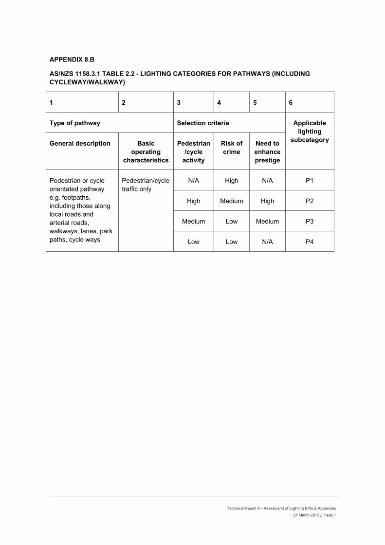
Technical Report 8 – Assess,emt of Ligjhting Effects Appencies 27 March 2012 // Page 1
APPENDIX 8.B
AS/NZS 1158.3.1 TABLE 2.2 - LIGHTING CATEGORIES FOR PATHWAYS (INCLUDING CYCLEWAY/WALKWAY)
1 2 3 4 5 6
Type of pathway Selection criteria Applicable lighting
subcategory General description Basic operating
characteristics
Pedestrian/cycle
activity
Risk of crime
Need to enhance prestige
Pedestrian or cycle orientated pathway e.g. footpaths, including those along local roads and arterial roads, walkways, lanes, park paths, cycle ways
Pedestrian/cycle traffic only
N/A High N/A P1
High Medium High P2
Medium Low Medium P3
Low Low N/A P4
Lum
minaire D
ApDescriptio
ppendix 8on Schedu
8.C ule
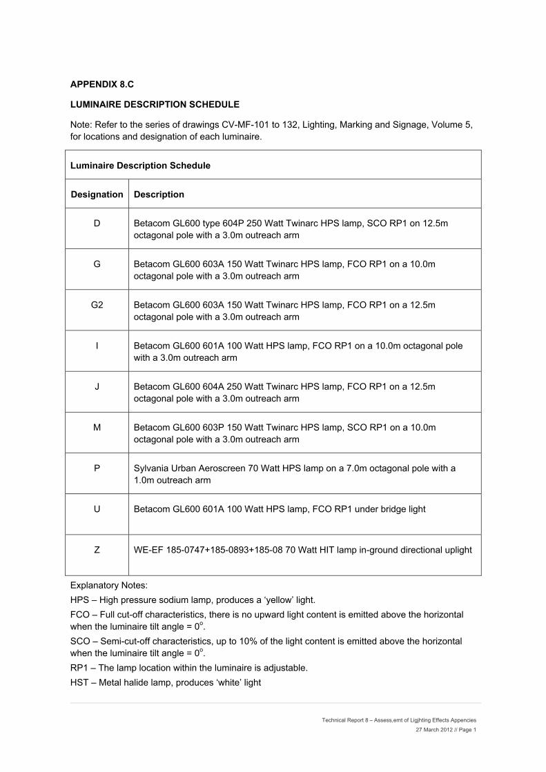
Technical Report 8 – Assess,emt of Ligjhting Effects Appencies 27 March 2012 // Page 1
APPENDIX 8.C
LUMINAIRE DESCRIPTION SCHEDULE
Note: Refer to the series of drawings CV-MF-101 to 132, Lighting, Marking and Signage, Volume 5, for locations and designation of each luminaire.
Luminaire Description Schedule
Designation Description
D Betacom GL600 type 604P 250 Watt Twinarc HPS lamp, SCO RP1 on 12.5m octagonal pole with a 3.0m outreach arm
G Betacom GL600 603A 150 Watt Twinarc HPS lamp, FCO RP1 on a 10.0m octagonal pole with a 3.0m outreach arm
G2 Betacom GL600 603A 150 Watt Twinarc HPS lamp, FCO RP1 on a 12.5m octagonal pole with a 3.0m outreach arm
I Betacom GL600 601A 100 Watt HPS lamp, FCO RP1 on a 10.0m octagonal pole with a 3.0m outreach arm
J Betacom GL600 604A 250 Watt Twinarc HPS lamp, FCO RP1 on a 12.5m octagonal pole with a 3.0m outreach arm
M Betacom GL600 603P 150 Watt Twinarc HPS lamp, SCO RP1 on a 10.0m octagonal pole with a 3.0m outreach arm
P Sylvania Urban Aeroscreen 70 Watt HPS lamp on a 7.0m octagonal pole with a 1.0m outreach arm
U Betacom GL600 601A 100 Watt HPS lamp, FCO RP1 under bridge light
Z WE-EF 185-0747+185-0893+185-08 70 Watt HIT lamp in-ground directional uplight
Explanatory Notes:
HPS – High pressure sodium lamp, produces a ‘yellow’ light.
FCO – Full cut-off characteristics, there is no upward light content is emitted above the horizontal when the luminaire tilt angle = 0o.
SCO – Semi-cut-off characteristics, up to 10% of the light content is emitted above the horizontal when the luminaire tilt angle = 0o.
RP1 – The lamp location within the luminaire is adjustable.
HST – Metal halide lamp, produces ‘white’ light

Te
Table 2echnical P
2.1 - RecParamete
commenders For Th
ded Maximhe Contro
Apmum Valol Of Obt
ppendix 8ues of Ligrusive Lig
8.D ght ght

Technical Report 8 – Assess,emt of Ligjhting Effects Appencies 27 March 2012 // Page 1
APPENDIX 8.D
TABLE 2.1 - RECOMMENDED MAXIMUM VALUES OF LIGHT TECHNICAL PARAMETERS FOR THE CONTROL OF OBTRUSIVE LIGHT
1 2 3 4 5
Light technical parameter
Application or calculation conditions (see also Figure 2.1 and Section 5)
Recommended maximum values
In commercial areas or at boundary of commercial
and residential
areas*
Residential areas
Light surrounds†
Dark surrounds‡
Illuminance in vertical plane (Ev)
Pre-curfew: Limits apply at relevant boundaries of nearby residential properties, in a vertical plane parallel to the relevant boundary, to a height commensurate with the height of the potentially affected dwellings. Values given are for the direct component of illuminance
25 lx 10 lx 10 lx
Curfewed hours: Limits apply in the plane of the windows of habitable rooms of dwellings on nearby residential properties. In the absence of development (i.e. vacant allotment), the limits apply on the potentially affected property, in a vertical plane parallel to the relevant boundary, at the minimum setback permitted for a dwelling, to a height commensurate with land use zoning provisions. Values given are for the direct component of illuminance
4 lx 2 lx 1 lx
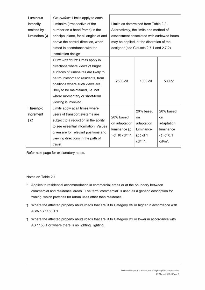
Technical Report 8 – Assess,emt of Ligjhting Effects Appencies 27 March 2012 // Page 2
Luminous intensity emitted by luminaires (I)
Pre-curfew : Limits apply to each luminaire (irrespective of the number on a head frame) in the principal plane, for all angles at and above the control direction, when aimed in accordance with the installation design
Limits as determined from Table 2.2. Alternatively, the limits and method of assessment associated with curfewed hours may be applied, at the discretion of the designer (see Clauses 2.7.1 and 2.7.2)
Curfewed hours: Limits apply in directions where views of bright surfaces of luminaires are likely to be troublesome to residents, from positions where such views are likely to be maintained, i.e. not where momentary or short-term viewing is involved
2500 cd 1000 cd 500 cd
Threshold increment (TI)
Limits apply at all times where users of transport systems are subject to a reduction in the ability to see essential information. Values given are for relevant positions and viewing directions in the path of travel
20% based on adaptation luminance (L ) of 10 cd/m².
20% based on adaptation luminance (L ) of 1 cd/m².
20% based on adaptation luminance (L) of 0.1 cd/m².
Refer next page for explanatory notes.
Notes on Table 2.1
* Applies to residential accommodation in commercial areas or at the boundary between commercial and residential areas. The term ‘commercial’ is used as a generic description for zoning, which provides for urban uses other than residential.
† Where the affected property abuts roads that are lit to Category V5 or higher in accordance with AS/NZS 1158.1.1.
‡ Where the affected property abuts roads that are lit to Category B1 or lower in accordance with AS 1158.1 or where there is no lighting. lighting.

DDiagrams Demons
strating th
Ap
he LuminaCha
ppendix 8
aire Cut-Oracteristi
8.E
Off cs.
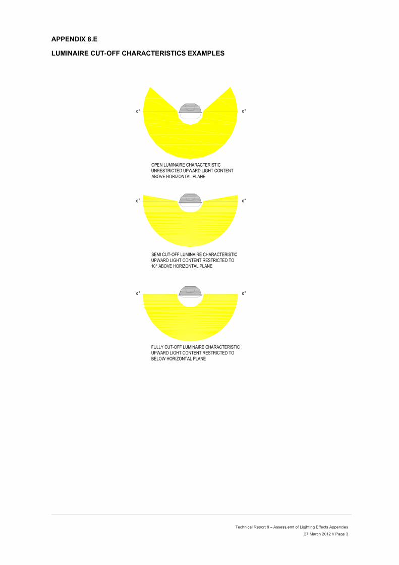
Technical Report 8 – Assess,emt of Ligjhting Effects Appencies 27 March 2012 // Page 3
APPENDIX 8.E
LUMINAIRE CUT-OFF CHARACTERISTICS EXAMPLES
o°
OPEN LUMINAIRE CHARACTERISTICUNRESTRICTED UPWARD LIGHT CONTENTABOVE HORIZONTAL PLANE
o°
o°
SEMI CUT-OFF LUMINAIRE CHARACTERISTICUPWARD LIGHT CONTENT RESTRICTED TO10° ABOVE HORIZONTAL PLANE
o°
o°
FULLY CUT-OFF LUMINAIRE CHARACTERISTICUPWARD LIGHT CONTENT RESTRICTED TOBELOW HORIZONTAL PLANE
o°
Luuminaire Back SpAp
pill Light Cppendix 8Calculatio
8.F ons

P:\332\3320901\Lighting\Resource Consent\Documents\KMG_1_Rev D_WGNDOC01-1453600-v2-Second_Review_-_M2PP_Assessment_of_Lighting_Effects.doc 17 February 2012 // Page 1
0 0 0 0 0 0 0 0 0 0 0 0 0 0 0 0 0 0 0 0 0 0 0 00 0 0 0 0 0 0 0 0 0 0 0 0 0 0 0 0 0 0 0 0 0 0 01 0 0 0 0 0 0 1 1 0 0 0 0 0 0 1 1 0 0 0 0 0 0 11 1 0 0 0 0 1 1 1 1 0 0 0 0 1 1 1 1 0 0 0 0 1 12 1 1 0 0 1 1 2 2 1 1 0 0 1 1 2 2 1 1 0 0 1 1 23 2 1 1 1 1 2 3 3 2 1 1 1 1 2 3 3 2 1 1 1 1 2 35 2 1 1 1 1 2 5 5 2 1 1 1 1 2 5 5 2 1 1 1 1 2 58 4 1 1 1 1 4 8 8 4 1 1 1 1 4 8 8 4 1 1 1 1 4 813 5 2 1 1 2 5 13 13 5 2 1 1 2 5 13 13 5 2 1 1 2 5 1319 8 3 2 2 3 8 19 19 8 3 2 2 3 8 19 19 8 3 2 2 3 8 19
DIST
ANCE
2m4m6m8m
10m12m14m16m18m20m
CENTRE LINE OF POLE
APPENDIX 8 F
LUMINAIRE BACK SPILL LIGHT CALCULATIONS
TYPE P LUMINAIRES (USED FOR CYCLE PATH LIGHTING)
70 Watt HPS on 7.0m high poles at nominal 40m centres.
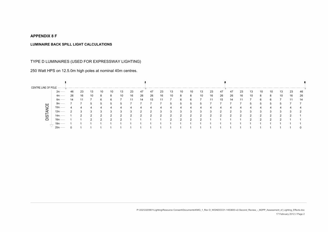
P:\332\3320901\Lighting\Resource Consent\Documents\KMG_1_Rev D_WGNDOC01-1453600-v2-Second_Review_-_M2PP_Assessment_of_Lighting_Effects.doc 17 February 2012 // Page 2
0 1 1 1 1 1 1 1 1 1 1 1 1 1 1 1 1 1 1 1 1 1 1 01 1 1 1 1 1 1 1 1 1 1 1 1 1 1 1 1 1 1 1 1 1 1 11 1 2 2 2 2 1 1 1 1 2 2 2 2 1 1 1 1 2 2 2 2 1 11 2 2 2 2 2 2 2 2 2 2 2 2 2 2 2 2 2 2 2 2 2 2 12 3 3 3 3 3 3 2 2 3 3 3 3 3 3 2 2 3 3 3 3 3 3 24 4 4 4 4 4 4 4 4 4 4 4 4 4 4 4 4 4 4 4 4 4 4 47 7 5 5 5 5 7 7 7 7 5 5 5 5 7 7 7 7 5 5 5 5 7 714 11 7 6 6 7 11 14 15 11 7 6 6 7 11 15 14 11 7 6 6 7 11 1426 16 10 8 8 10 16 26 26 16 10 8 8 10 16 26 26 16 10 8 8 10 16 2646 23 13 10 10 13 23 47 47 23 13 10 10 13 23 47 47 23 13 10 10 13 23 46
DIST
ANCE
2m4m6m8m
10m12m14m16m18m20m
CENTRE LINE OF POLE
APPENDIX 8 F
LUMINAIRE BACK SPILL LIGHT CALCULATIONS
TYPE D LUMINAIRES (USED FOR EXPRESSWAY LIGHTING)
250 Watt HPS on 12.5.0m high poles at nominal 40m centres.

P:\332\3320901\Lighting\Resource Consent\Documents\KMG_1_Rev D_WGNDOC01-1453600-v2-Second_Review_-_M2PP_Assessment_of_Lighting_Effects.doc 17 February 2012 // Page 3
DIST
ANCE
2m4m6m8m
10m12m14m16m18m20m
CENTRE LINE OF POLE
0 0 0 1 1 0 0 0 0 0 0 1 1 0 0 0 0 0 0 1 1 0 0 01 1 1 1 1 1 1 1 1 1 1 1 1 1 1 1 1 1 1 1 1 1 1 11 1 1 1 1 1 1 1 1 1 1 1 1 1 1 1 1 1 1 1 1 1 1 11 1 1 1 1 1 1 1 1 1 1 1 1 1 1 1 1 1 1 1 1 1 1 12 2 2 2 2 2 2 2 2 2 2 2 2 2 2 2 2 2 2 2 2 2 2 23 3 3 2 2 3 3 4 4 3 3 2 2 3 3 4 4 3 3 2 2 3 3 36 4 3 3 3 3 4 6 6 4 3 3 3 3 4 6 6 4 3 3 3 3 4 69 6 4 4 4 4 6 9 9 6 5 4 4 5 6 9 9 6 4 4 4 4 6 914 9 6 4 4 6 9 14 14 9 6 4 4 6 9 14 14 9 6 4 4 6 9 1420 12 7 5 5 7 12 20 20 12 7 5 5 7 12 20 20 12 7 5 5 7 12 20
APPENDIX 8 F
LUMINAIRE BACK SPILL LIGHT CALCULATIONS
TYPE G or TYPE J LUMINAIRES (USED FOR EXPRESSWAY LIGHTING)
150 Watt HPS on 10.0m high poles at nominal 40m centres.
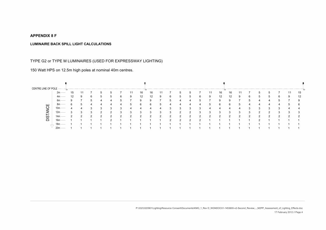
P:\332\3320901\Lighting\Resource Consent\Documents\KMG_1_Rev D_WGNDOC01-1453600-v2-Second_Review_-_M2PP_Assessment_of_Lighting_Effects.doc 17 February 2012 // Page 4
DIST
ANCE
2m4m6m8m
10m12m14m16m18m20m
CENTRE LINE OF POLE
1 1 1 1 1 1 1 1 1 1 1 1 1 1 1 1 1 1 1 1 1 1 1 11 1 1 1 1 1 1 1 1 1 1 1 1 1 1 1 1 1 1 1 1 1 1 11 1 1 1 2 1 1 1 1 1 2 2 2 2 1 1 1 1 1 2 1 1 1 12 2 2 2 2 2 2 2 2 2 2 2 2 2 2 2 2 2 2 2 2 2 2 23 3 3 2 2 3 3 3 3 3 3 2 2 3 3 3 3 3 3 2 2 3 3 34 4 3 3 3 3 4 4 4 4 3 3 3 3 4 4 4 4 3 3 3 3 4 46 5 4 4 4 4 5 6 6 5 4 4 4 4 5 6 6 5 4 4 4 4 5 69 7 5 4 4 5 7 9 9 7 5 4 4 5 7 9 9 7 5 4 4 5 7 912 9 6 5 5 6 9 12 12 9 6 5 5 6 9 12 12 9 6 5 5 6 9 1215 11 7 5 5 7 11 16 16 11 7 5 5 7 11 16 16 11 7 5 5 7 11 15
APPENDIX 8 F
LUMINAIRE BACK SPILL LIGHT CALCULATIONS
TYPE G2 or TYPE M LUMINAIRES (USED FOR EXPRESSWAY LIGHTING)
150 Watt HPS on 12.5m high poles at nominal 40m centres.
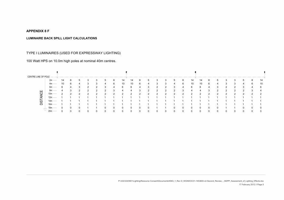
P:\332\3320901\Lighting\Resource Consent\Documents\KMG_1_Rev D_WGNDOC01-1453600-v2-Second_Review_-_M2PP_Assessment_of_Lighting_Effects.doc 17 February 2012 // Page 5
DIST
ANCE
2m4m6m8m
10m12m14m16m18m20m
CENTRE LINE OF POLE
0 0 0 0 0 0 0 0 0 0 0 0 0 0 0 0 0 0 0 0 0 0 0 00 0 0 1 1 0 0 0 0 0 0 1 1 0 0 0 0 0 0 1 1 0 0 01 1 1 1 1 1 1 1 1 1 1 1 1 1 1 1 1 1 1 1 1 1 1 11 1 1 1 1 1 1 1 1 1 1 1 1 1 1 1 1 1 1 1 1 1 1 11 1 1 1 1 1 1 1 1 1 1 1 1 1 1 1 1 1 1 1 1 1 1 12 2 2 2 2 2 2 2 2 2 2 2 2 2 2 2 2 2 2 2 2 2 2 24 3 2 2 2 2 3 4 4 3 2 2 2 2 3 4 4 3 2 2 2 2 3 46 4 3 2 2 3 4 6 6 4 3 2 2 3 4 6 6 4 3 2 2 3 4 610 6 4 3 3 4 6 10 10 6 4 3 3 4 6 10 10 6 4 3 3 4 6 1014 8 5 3 3 5 8 14 14 8 5 3 3 5 8 14 14 8 5 3 3 5 8 14
APPENDIX 8 F
LUMINAIRE BACK SPILL LIGHT CALCULATIONS
TYPE I LUMINAIRES (USED FOR EXPRESSWAY LIGHTING)
100 Watt HPS on 10.0m high poles at nominal 40m centres.