technical report for professional intervie report_rr.pdf · technical report for professional...
TRANSCRIPT

Technical Report for Professional Interview
Prepared by: Dr Rizauddin Ramli
Department of Mechanical and Material Engineering,
Faculty of Engineering & Built Environment,
Universiti Kebangsaan Malaysia,
Development of servo controlled Reciprocating
Gait Orthosis(RGO)
1. Introduction
Nowadays, we are exposed to various types of chronic illnesses and accident. Unexpected
accidents and illnesses can cause permanent changes in body and certainly affect the quality
of a person’s life. However with the advances in health, medical treatment and technology
enable people to survive and live longer. For example, patients with spinal cord injury
normally require a long time to recover and in the same time need to adapt rehabilitation
treatment persistently.
One of the reasons which is causing the paraplegia is because of the breakage in motor or
sensory function of the lower extremities due to complete or incomplete spinal cord injury,
which may cause by accident or other illness [1]. The paraplegia patients with non-
permanent disabilities always have tendency to walk again and are advised for rehabilitation
therapy [2]. With today’s modern technology, various types of orthoses and support tools
have been designed in order to help the paraplegia patients in their rehabilitation treatment.
An orthosis is a tool that usually used for patients with paralysis of legs or paraplegia
patients for their recovery and mobility purposes.
For example, there are many orthopedic devices such as Knee-Ankle-Foot Orthoses (KAFOs),
Walkabout Orthosis (WO), Hip-Knee-Ankle Foot Orthoses(HKAFO), Total Knee Arthopastry
(TKA), Reciprocating Gait Orthoses (RGO) have been developed and commercialized.
According to a study by Carina et al.[3], RGO is a device consists of a trunk support, a pelvis
band and bilateral knee-ankle-foot othoses which are connected with dual-cable movable
hip joint. The coupling of both hips gives hip stability during standing by preventing
simultaneous flexion. Flexion in hip activates the cable system to extend the contralateral
hip and permitting ambulation. Disconnection of hip and knee joints permits simultaneous
flexion for sitting.
Jefferson et al. [4] studied pattern of movement, hip joint motion, and general gait
parameter for the three type of orthosis which are Hip Guidance Orthosis(HGO),
Reciprocating Gait Orthosis(RGO) and Steeper’s Orthosis. Observation that hip abduction in
HGO is greater than other two devices and this makes HGO more suitable for the use with

crutches. RGO and Steeper’s orthosis could achieve stride length entirely by degree of
flexion or extension at hip joints. Although these two orthoses show similar pattern and
movement, Steeper’s orthosis made sitting and standing much easier with corresponding
advantages to patients. Solomonow et al. [5] found that RGO powered with electrical
stimulation of thigh muscles as secondary rehabilitation phase (RGO II) benefits patient
paraplegia. After a couples of time using the RGO II, most of the patients could walk
independently on grass, ramps and curbs, don and doff, stand up from seated position,
ambulate at least 180m, all without assistance. The RGO II were performed with this
objective, allowing paraplegics to put on and use the orthosis at any time without expecting
an assistance. Besides, regular use of RGO had a general positive impact on the patients'
health and outlook.
In addition, there is another research regarding Powered Gait Orthosis (PGO). PGO is a
modification of an RGO, incorporating two pneumatic muscle actuators (PMA), a
compressed air system, and pressure and joint angle sensors. Each hip joint of the PGO is
flexed by an air muscle operated by pressurized air, enabling the patient to walk. In the PGO
gait, since the hip joint is flexed by the air muscle and not by the rotation of the trunk, the
movement of the center of the body appears to be more stable than that of the RGO gait [6].
There is a comparison study among different types of orthoses that has been carried out by
Abe in 2006[7]. The study showed that the RGO demonstrate a superior performance in the
terms of static equilibrium, walking velocity and energy consumption compared to Knee-
Ankle-Foot Orthosis (KAFO) and Walkabout Orthosis (WO). Paraplegia patients had
significantly superior balance maintenance capability when they are using the RGO rather
than when they are using the WO or KAFO. This superior capability may be attributed to the
stability of anteroposterior and lateral directions in pelvis and hip joints. Maintenance of
paraplegic standing depends on the iliofemoral ligament with hyperextension in the hip
joint. However most of the orthoses above are called a passive orthotic devices or passive
RGO which means it must be moved with high energy by paraplegia patients.
Therefore, in this report, a development and design process of a servo controlled
reciprocating gait orthosis (RGO) to assist paraplegic patients for their rehabilitation
treatment is presented. There are at least three main problems faced by the current passive
RGO need to be addressed.
1- The design of RGO is complicated compared to other orthoses. It is due to the difficulties
of wearing and removing the device especially for children. The RGO normally is a
mechanical device which needed to be moved by user with the help of clutches.
2- Higher energy consumption is required for the users.
3- The manufacturing cost of a RGO is expensive because the size of RGO is highly
depended on the size body of user.
The main objectives of developing the RGO are to design a simple, easy and friendly user
structure RGO and to minimize the energy consumption of RGO users. Also the aim is to
fabricate a RGO by using at minimum cost.

In the design of the RGO, an anthropometric data provides a useful guidance to determine
the size of structure. According to a survey conducted by Karmegam et al. [8], the mean
weights is 72.57kg for Malays, and for the Chinese and India is 64.17kg and 65.32kg
respectively. The survey was carried out at the age of 18 years to 24 years of respondents.
So, this becomes the reference for the design of the RGO size. Table 1 shows a comparison
in terms of weight and height among the three major races in Malaysia.
Table 1: Comparison in terms of weight and height among the three major races in
Malaysia.
Characteristic Male Female
Malay Chinese Indian Malay Chinese Indian
Weight (kg) 72.57 64.17 65.32 57.97 55.82 55.59
Height (cm) 178.57 169.38 168.1 153.3 158.58 156.83
(Source : Karmegam et al. 2011)
2. Design Process
The design objective of servo controlled RGO is to build a prototype that will possess the
ability to help paraplegia patients in their mobility option. Servomotors are used for mobility
purpose, and it is designed in simple structure. Therefore in this study, the design concept
and analysis is playing the vital role before fabricating the prototype of the servo controlled
RGO.
First, a lot of information about function and designs of RGO has been investigated through
literature review, patents, catalogs and online study. Table 2 shows various type of orthosis
that have been considered as comparison. Next, in order to generate design concept to
perform each major function of RGO, a brainstorming section is held and a sketch of the
initial design of each structure is done.
Multiple design concept generation will lead us subject them to an evaluation scheme in
order to determine the best concept. Morphological chart method is used to uncover
combinations of ideas and Pugh’s concept selection method helps to evaluate and compare
among the ideas generated [9]. The next stage is where design concept is invested with
physical form which is called embodiment design. Form of parts will satisfy the required
functions of RGO. The parametric design of this RGO is depended on the anthropometric
data. The structure part of RGO is designed symmetry except foot plate. When the
conceptual design and embodiment design are established, drawing of all parts in RGO is
constructed by AutoDesk Inventor Professional 2010. Figure 1 shows the flowchart of the
development process in this study.
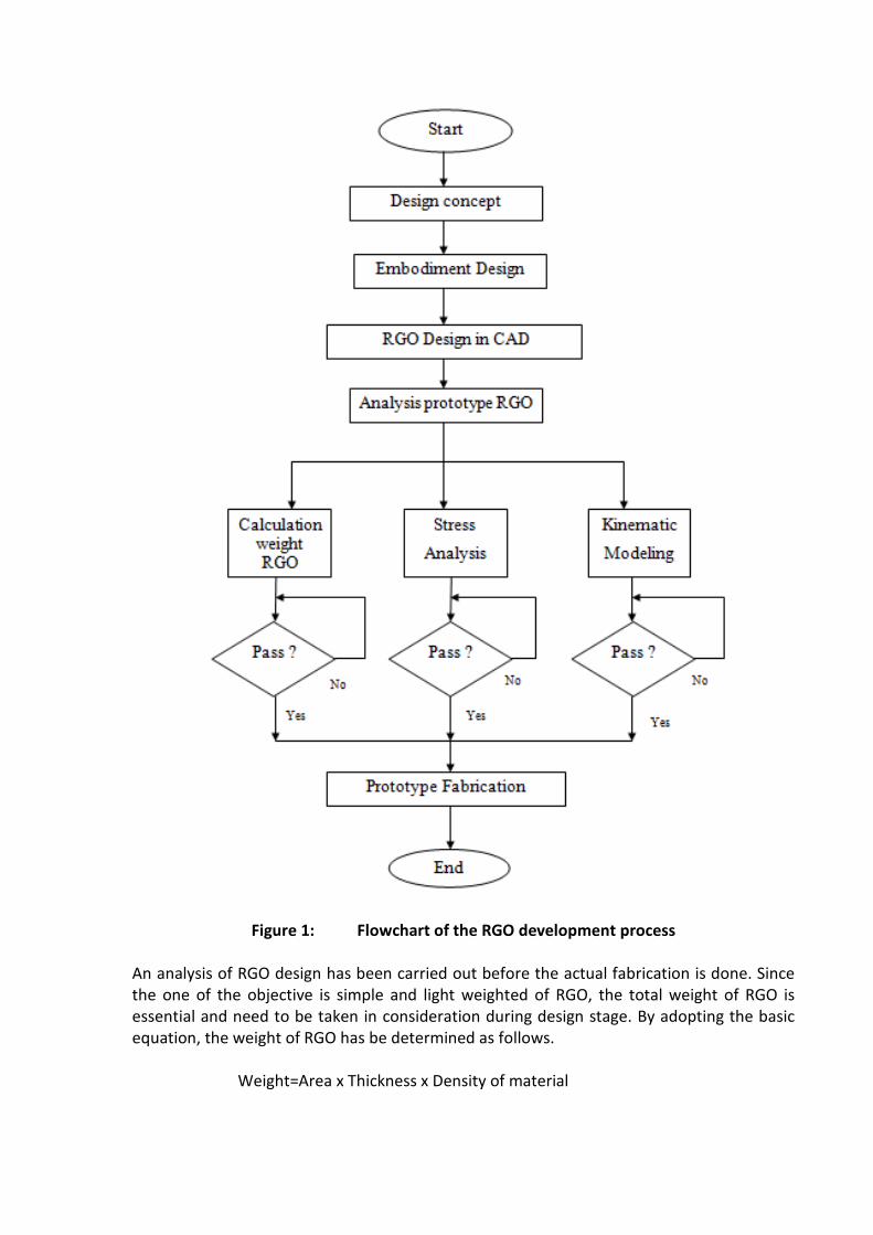
Figure 1: Flowchart of the RGO development process
An analysis of RGO design has been carried out before the actual fabrication is done. Since
the one of the objective is simple and light weighted of RGO, the total weight of RGO is
essential and need to be taken in consideration during design stage. By adopting the basic
equation, the weight of RGO has be determined as follows.
Weight=Area x Thickness x Density of material

The material used for the fabrication RGO is Aluminium. The purpose of choosing aluminium
as material for the structure of the RGO is to because to have a light weighted orthosis. This
will contribute to less energy consumption of patient paraplegia.
The developed RGO consists of five main components which are waist plate, upper thigh
plate, thigh plate, knee plate and foot plate as shown in Figure 2.
Figure 2: Complete Design of 4DOF RGO
3. Kinematic model
Kinematic modeling is carried out for the purpose of torque analysis. Figure 3 shows a
2dimension schematic view of the simplified model of the RGO structure. A reference frame
{O} is set as reference point while frame {A} is attached to the foot and frame {B} is attached
to the body. , and are the angles of the ankle, knee and hip.
The forward kinematic from frame {A} to frame {B} is as follows,

(1)
Figure 3: 2D model of single leg of RGO
In robotics, a Jacobian matrix is commonly used to represent the velocity and angular
velocity. Partial differentiation of will produce Jacobian matrix, which is shown as below.
= (2)
= (3)
= (4)
Then, Equation (2)-(4) is simplified as,
-
-
- +θ
L1
L2
A
B
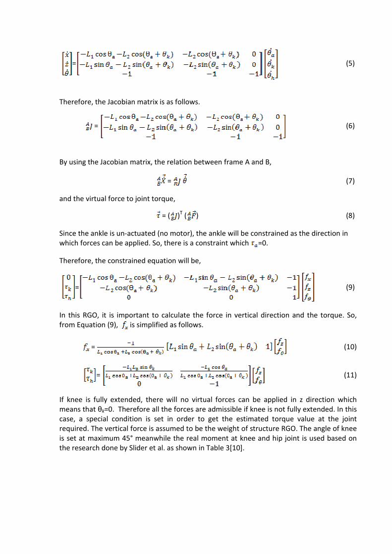
= (5)
Therefore, the Jacobian matrix is as follows.
= (6)
By using the Jacobian matrix, the relation between frame A and B,
= (7)
and the virtual force to joint torque,
= ( )T ( ) (8)
Since the ankle is un-actuated (no motor), the ankle will be constrained as the direction in
which forces can be applied. So, there is a constraint which =0.
Therefore, the constrained equation will be,
= (9)
In this RGO, it is important to calculate the force in vertical direction and the torque. So,
from Equation (9), is simplified as follows.
= (10)
= (11)
If knee is fully extended, there will no virtual forces can be applied in z direction which
means that θk=0. Therefore all the forces are admissible if knee is not fully extended. In this
case, a special condition is set in order to get the estimated torque value at the joint
required. The vertical force is assumed to be the weight of structure RGO. The angle of knee
is set at maximum 45° meanwhile the real moment at knee and hip joint is used based on
the research done by Slider et al. as shown in Table 3[10].


Table 3: Moment at lower limb of human being
Moment(Nm)
Measured
Hip Knee Ankle
2.5 1.4 0.7
Predicted 2.1 1.2 0.4
(Source: Slider et al. 2007[10])
The length of link L1 and L2 of the RGO is shown in Figure 4.
Figure 4: Two degree of freedom at each side RGO with link length (unit in mm)
4. Stress analysis
Stress analysis is carried out by using Autodesk Inventor 2010 to determine whether RGO
can stand the total weight which based on anthropometric data by Karmegam et al. [8]. In
this case, assumptions are made as following. The load or weight of a person is divided half
and applied to the foot plate, knee plate, thigh plate and upper thigh plate. The average of a
person’s weight is assumed as 73kg.
The analysis on RGO structure is conducted to visual the capability of material withstand the
force applied. Figure 5(a) shows stress distribution and location of stress occurs on the RGO
structure. Result reveals that maximum stress (Von Mises) 37.86MPa located at each foot
plate due to the force applied almost focusing at the particular part. Figure 5(b) indicates
the displacement occurs when subjected to load of 73kg. The maximum displacement is
7.487mm which happen at each foot plate toward the center of RGO. The safety factor of
RGO is at minimum 7.26 which mean the structural system is capable beyond the expected
load.
L1
L2

Figure 5 (a): Stress Distribution of RGO.

5 (b): Displacement distribution of RGO
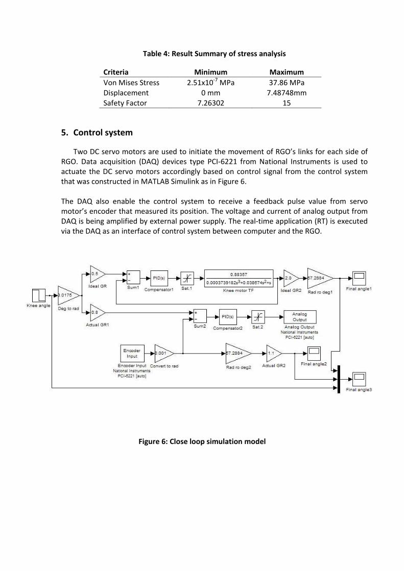
Table 4: Result Summary of stress analysis
Criteria Minimum Maximum
Von Mises Stress 2.51x10⁻⁷
MPa 37.86 MPa
Displacement 0 mm 7.48748mm
Safety Factor 7.26302 15
5. Control system
Two DC servo motors are used to initiate the movement of RGO’s links for each side of
RGO. Data acquisition (DAQ) devices type PCI-6221 from National Instruments is used to
actuate the DC servo motors accordingly based on control signal from the control system
that was constructed in MATLAB Simulink as in Figure 6.
The DAQ also enable the control system to receive a feedback pulse value from servo
motor’s encoder that measured its position. The voltage and current of analog output from
DAQ is being amplified by external power supply. The real-time application (RT) is executed
via the DAQ as an interface of control system between computer and the RGO.
Figure 6: Close loop simulation model

6. Conclusions
The RGO that has been developed is shown in Figure 7. It is designed to be a simple, light
weighted and user friendly RGO. It had four degree of freedom in the structure, with flexion
at hip joint and knee joint. The usage of the DC servo motor decreases the energy
consumption of the patients. Cost of manufacturing RGO is less compared to the
commercial RGO in market.
References
1- Handbook of Spinal Cord Injuries, 2nd
Edition, pp. 7--15, Queensland Spinal Cord Injuries
Service, Australia (2001)
2- Chirazi, M.: Practical Applications of the Passive Range of Motion on the Paraplegic
Rehabilitation. In: WCB 2010, IFMBE Proceedings 31, pp.985--987. Springerlink (2010)
3- Carina L. E. Gerritsma-Bleekers, Heeg, M. & Hanna Vos-Niel. 1997. Ambulation with the
reciprocating gait orthosis. Acta Orthop Scand. 68(5):470-473.
4- Jefferson, R.J. & Whittle, M.W. 1990. Performance of three walking orthoses for the
paralysed: a case study using gait analysis. Prosthetics and Orthotics International.
14:103-110.
5- Solomonow, M., Aguilar, E., Reisin, E., Baratta, R.V., Best, R., Coetzee, T. & D’Ambrosia, R.
1997. Reciprocating Gait Orthosis Powered with Electrical Muscle Stimulation (RGO II).
Part I : Performance Evaluation of 70 Paraplegic Patients. Orthopedics 20(4): 315-324.
6- Kang, S.J., Ryu, J.C., Moon, I.H., Kim, K.H., & Mun, M.S. 2007. Walker Gait Analysis of
Powered Gait Orthosis for Paraplegic. World Congress on Medical Physics and
Biomedical Engineering 2006. 14: 2889-2891.
7- Abe Kaoru. 2006. Comparison of Static Balance, Walking Velocity, and Energy
Consumption with Knee-Ankle-Foot Orthosis, Walkabout Orthosis, and Reciprocating
Gait Orhtosis in Thoracic-Level Paraplegic Patients. Journal of Prosthetics and Orthotics
18(3): 87-90.
8- Karmegam, K., Sapuan, S. M., Ismail, M. Y., Ismail, N., Shamsul Bahri, M. T., Shuib, S.,
Mohana, G. K., Seetha, P., TamilMoli P. & Hanapi, M.J. 2011. Anthropometric study
among adults of different ethnicity in Malaysia. International Journal of the Physical
Sciences 6(4): 777-788.
9- Dieter, G.E. 2000. Engineering Design: A Materials and Processing Approach 3rd
Edition.
New York:Mc Graw Hill
10- Silder Amy, Whittington Ben, Heiderscheit Bryan & Thelen Darryl B. 2007. Identification
of passive elastic joint moment-angle relationships in the lower extremity. Journal of
Biomechanics 40:2628-2635.

Figure 7: Actual RGO after fabrication and assembly