technical report for the design, construction ...sparc/documents/pdf_files/06_01_06_sparc_tr.pdf ·...
TRANSCRIPT

1
LOI Identification Nº21. [ * obtained from the FAIR project team] FAIR- PAC: make cross
where applicable APPA [ X ]
NUSTAR [ * ] QCD [ * ] Date: 15/12/2005 Technical Report for the Design, Construction, Commissioning and Operation of the SPARC Project: Stored Particle Atomic Physics Collaboration at the FAIR Facility The SPARC Collaboration Abstract: The future international accelerator Facility for Antiproton and Ion Research has key features that offer a wide range of new and challenging opportunities for atomic physics and related fields. In SPARC we plan experiments in two major research areas: collision dynamics in strong electromagnetic fields and fundamental interactions between electrons and heavy nuclei up to bare uranium. In the first area we will use the relativistic heavy ions for a wide range of collision studies. In the extremely short, relativistically enhanced field pulses, the critical field limit (Schwinger limit) for lepton pair production can be surpassed by orders of magnitudes and a breakdown of perturbative approximations for pair production is expected. The detection methods of reaction microscopes will give the momentum of all fragments when atoms or molecules are disintegrating in strong field pulses of the ions. This allows to explore the regimes of multi-photon processes that are still far from being reached with high-power lasers. For medium and low energies, the cooler rings NESR - a "second-generation" ESR – and the low-energy ring LSR, with optimized features and novel installations such as an ultra-cold electron target will be exploited for collision studies. Fundamental atomic processes can be investigated in a kinematically complete fashion for the interaction of cooled heavy-ions up to bare uranium with photons, electrons and atoms. These studies extend into the low-energy regime where the atomic interactions are dominated by strong perturbations and quasi-molecular effects. The other class of experiments will focus on structure studies of selected highly-charged ion species, a field which is still largely unexplored. The properties of stable and unstable nuclei will become accessible by atomic physics techniques along with precision tests of quantum electrodynamics (QED) in extremely strong electromagnetic fields. Different complementary approaches will be used: coherent excitation by channeling of relativistic ions, electron-ion recombination, electron and photon spectroscopy. All of these give hitherto unreachable accuracies. The relativistic Doppler boost of optical or X-UV laser photons into the X-ray regime can now be applied to precision spectroscopy at high-Z and to laser-cool the relativistic heavy ions to extremely low temperature. Due to the expected gain in luminosity, this may have a considerable impact on accelerator technology. Another important scenario for this class of experiments will be the slowing-down, trapping and cooling of particles in the ion trap facility HITRAP. This will enable not only high-accuracy experiments in the realm of atomic and nuclear physics but as well highly-sensitive tests of the Standard Model. Spokesperson, email, telephone number Reinhold Schuch, University of Stockholm [email protected], +46 855378621
2
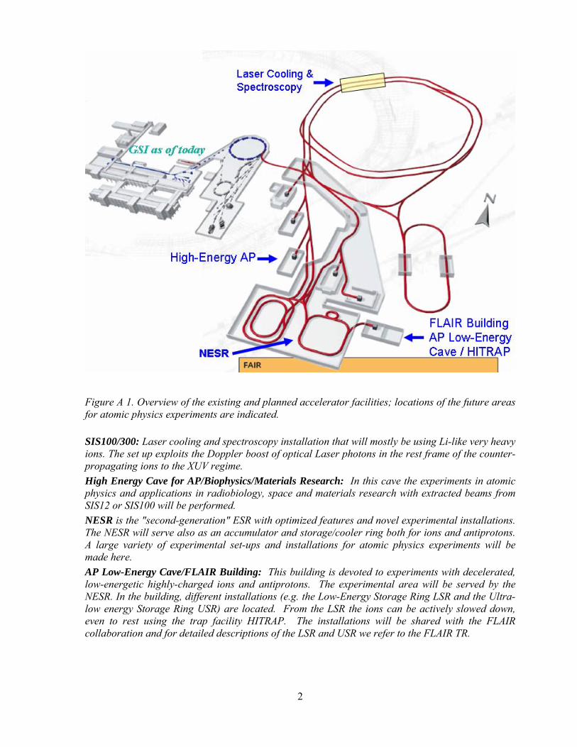
Figure A 1. Overview of the existing and planned accelerator facilities; locations of the future areas for atomic physics experiments are indicated. SIS100/300: Laser cooling and spectroscopy installation that will mostly be using Li-like very heavy ions. The set up exploits the Doppler boost of optical Laser photons in the rest frame of the counter-propagating ions to the XUV regime. High Energy Cave for AP/Biophysics/Materials Research: In this cave the experiments in atomic physics and applications in radiobiology, space and materials research with extracted beams from SIS12 or SIS100 will be performed. NESR is the "second-generation" ESR with optimized features and novel experimental installations. The NESR will serve also as an accumulator and storage/cooler ring both for ions and antiprotons. A large variety of experimental set-ups and installations for atomic physics experiments will be made here. AP Low-Energy Cave/FLAIR Building: This building is devoted to experiments with decelerated, low-energetic highly-charged ions and antiprotons. The experimental area will be served by the NESR. In the building, different installations (e.g. the Low-Energy Storage Ring LSR and the Ultra-low energy Storage Ring USR) are located. From the LSR the ions can be actively slowed down, even to rest using the trap facility HITRAP. The installations will be shared with the FLAIR collaboration and for detailed descriptions of the LSR and USR we refer to the FLAIR TR.

3
Collaborating Individuals and Institutions (Status: 12/12/2005) ARGENTINA Pablo D. Fainstein Centro Atomico Bariloche AUSTRIA Joachim Burgdoerfer, Christoph Lemell, Shuhei Yoshida Vienna University of Technolgy Friedrich Aumayr, Hannspeter Winter Institut fuer Allgemeine Physik, TU Wien CANADA Gerald Gwinner University of Manitoba Marko Horbatsch York University Jens Dilling TRIUMF National Laboratory Vancouver CHINA Xiantang Zeng China Institute of Atomic Energy, Beijing Jianguo Wang Institute of Applied Physics and Computational Mathematics, Beijing Chongyang Chen Institute of Modern Physics, Fudan University, Shanghai Xiaohong Cai, Xinwen Ma, Baoren Wei, Feng Shou Zhang, Xiaolong Zhu Institute of Modern Physics, Chinese Academy of Sciences, Lanzhou Dajun Ding Institute of Atomic and Molecular Physics, Jilin University, Jilin Chen Ximeng Lanzhou University, Lanzhou Ji Chen, Lin-fan Zhu University of Science and Technology of China, Hefei Kelin Gao Wuhan Institute of Physics and Mathematics, Wuhan Chenzhong Dong Physics Department, Northwest Normal University, Lanzhou Yaming Zou Applied Ion Beam Physics Laboratoy, Fudan University, Shanghai CROATIA Krunoslav Pisk, Tihomir Suric Ruder Boskovic Institute, Zagreb

4
CZECH REPUBLIC Oldrich Renner Institute of Physics, Czech Academy of Sciences, Prague DENMARK Lars Bojer Madsen Department of Physics and Astronomy, University of Aarhus EGYPT Hassan Hanafy, Tarek Mohamed Physics Department, Faculty of Science, Beni-Suef FRANCE Bruno Manil, Hermann Rothard CIRIL Ganil Alexandre Simionovici Ecole Normale Superieure – Lyon Denis Dauvergne Institut de Physique Nucléaire de Lyon Emily Lamour, Jean-Pierre Rozet Groupe de Physique des Solides, Paris Eric-Olivier Le Bigot Univ. P. & M. Curie et Ecole Normale Supérieure, Paris Dina Attia Laboratoire Kastler-Brossel Paris (UPMC/ENS) GERMANY Alexander Herlert, Gerrit H. Marx, Lutz Schweikhard Ernst Moritz Arndt Universität Greifswald Gerhard Baur, Detlev Gotta, Thomas Krings, Davor Protic, Frank Rathmann Forschungszentrum Jülich John Briggs, Ulrich Jentschura Freiburg University Dietrich Beck, Frank Becker, Thomas Beier, Heinrich F. Beyer, Michael Block, Fritz Bosch, Angela Braeuning-Demian, Carsten Brandau, Peter Egelhof, Alexandre Gumberidze, Thomas Hahn, Frank Herfurth, H.-Jürgen Kluge, Christophor Kozhuharov, Thomas Kühl, Dieter Liesen, Rido Mann, Paul Mokler, Manas Mukherjee, Wolfgang Quint, Saidur Rahaman, Rodolfo Sanchez, Haik Simon, Thomas Stöhlker, Marco Tomasseli, Sergiy Trotsenko, Christine Weber GSI, Darmstadt Harald Bräuning, Alfred Müller, Stefan Schippers Institut für Atom- und Molekülphysik, Justus-Liebig-Universität Gießen Werner Scheid Institut für Theoretische Physik der Universität Gießen Dietrich Habs, Ulrich Schramm Sektion Physik, LMU Munich Daniel Fischer, Christoph H. Keitel, Michael Lestinsky, Robert Moshammer, Sascha Reinhardt, Guido Saathoff, Frank Sprenger, Joachim Ullrich, Carsten Welsch, Andreas Wolf, Alexander Voitkiv
5
Max-Planck-Institut für Kernphysik, Heidelberg Oleg Yu. Andreev, Guenter Plunien, Ralf Schützhold, Gerhard Soff, Andrei Volotka Institut für Theoretische Physik, TU Dresden Wilfried Nörtershäuser Institut für Kernchemie, Universität Mainz Reinhard Dörner, R. Grisenti, Siegbert Hagmann, Horst Schmidt-Böcking, Kurt Ernst Stiebing IKF, J.W.v.Goethe Universität Frankfurt am Main Hartmut Backe, Slobodan Djekic, Gerhard Huber, Sergej Karpuk, Christian Novotny, Stefan Stahl, Manuel Vogel Institut für Physik, Universität Mainz Josef Anton, Burkhard Fricke, Stephan Fritzsche, Wolf-Dieter Sepp, Andrey Surzhykov Institut für Physik, Universität Kassel Tom Kirchner Institut für Theoretische Physik, TU Clausthal Andreas Fleischmann Kirchhoff-Institut für Physik, Universität Heidelberg Andreas Zilges TU Darmstadt Volker Dangendorf Physikalisch-Technische Bundesanstalt, Braunschweig Doris Jakubassa-Amundsen Mathematics Institute, University of Munich, 80333 Munich Günter Zwicknagel Theoretische Physik, Universität Erlangen Gerd Röpke Institut für Physik, Universität Rostock Joerg Eichler Hahn-Meitner-Institut Berlin Alejandro Saenz Humboldt-Universität zu Berlin Eckhart Förster Institute for Optics, Jena University GREECE Theo Zouros University of Crete and IESL-FORTH, Heraklion HUNGARY Béla Sulik, Karoly Tokesi Inst. of Nuclear Research (ATOMKI), Debrecen INDIA Krishnamurthy Manchikanti, Deepak Mathur, Lokesh Tribedi, Umesh Kadhane Tata Institute of Fundamental Research, Bombay Punita Verma Vaish College, Rohtak

6
Tapan Nandi, C P Safvan Nuclear Science Centre, New Delhi Brij Suri Bhabha Atomic Research Centre, New Delhi Debasis Mitra Saha Institute of Nuclear Physics, Calcutta ITALY Gaetano Lanzano Inst. Naz. Fisica Nucleare, Dip. di Fisica, Catania JAPAN Yasunori Yamazaki University of Tokyo & Atomic Physics Laboratory RIKEN, Wako JORDAN Feras Afaneh, Rami Ali Hashemite University, Zarqa MEXICO Carmen Cisneros CCF Universidad Nacional Autónoma de México NETHERLANDS Ronnie Hoekstra, Reinhard Morgenstern, Abel Robin KVI Atomic Physics, RijksUniversiteit Groningen POLAND Dariusz Banas, Marek Pajek, Institute of Physics, Swietokrzyska Academy, Kielce Stefan Samek, Andrzej Warczak Institute of Physics, Jagiellonian University, Cracow Krzysztof Pachucki Institute of Theoretical Physics, Warsaw University Zbigniew Stachura Institute of Nuclear Physics of Polish Academy of Sciences, Cracow Jacek Rzadkiewicz The Soltan Institute For Nuclear Studie, Swierks ROMANIA Constantin Ciortea, Dana Elena Dumitriu, Alexandru Enulescu, Daniela Fluerasu, Liviu Constantin Penescu, Aimee Theodora Radu NIPNE National Institute for Physics and Nuclear Engineering, Bukarest RUSSIA Leonid Presnyakov, Viatcheslav Shevelko

7
Lebedev Physical Institute, Moscow Oleg Yu Andreev, Anton Artemyev, Igor Goidenko, Leonti N. Labzowsky, Andrei Nefiodov, Vladimir Shabaev, Vladimir Yerokhin Institute of Physics, St. Petersburg State University Vitaly Pal'Chikov Institute of Metrology for Time and Space at VNIIFTR, MoscowI Lyudmila Bureyeva Institute of Spectroscopy of the RAS, Moscow Victor Varentsov V.G.Khlopin Radium Institute, St.Petersburg Vsevolod Balashov Institute of Nuclear Physics, Moscow State University Evgenii Drukarev Petersburg Nuclear Physics Institute Valery Lisitsa RRC "Kurchatov Institute" SERBIA AND MONTENEGRO Bratislav Marinkovic Institute of Physics, Belgrade SPAIN Gustavo Garcia CSIC, Madrid SWEDEN Ingvar Lindgren, Sten Salomonson Chalmers University of Technology and Goteborg University Eva Lindroth, Stojan Madzunkov, Szilard Nagy, Reinhold Schuch, György Vikor Stockholm University Glans Peter Mid-Sweden University, Sundsvall Roger Hutton Lund University Guillermo Andler, Lars Bagge, Håkan Danared, Mats Engström, Anders Källberg, Leif Liljeby, Patrik Löfgren, Andras Paál, K.-G. Rensfelt, Ansgar Simonsson Örjan Skeppstedt Manne Siegbahn Laboratory MSL, Stockholm SWITZERLAND Klaus Blaum Univ. Mainz Jean-Claude Dousse, Matjaz Kavcic, Jakub Szlachetko Department of Physics, University Fribourg Kai Hencken, Dirk Trautmann Institut für Physik, Universität Basel

8
UNITED KINGDOM Robert Potvliege Department of Physics, The University of Durham Fred Currell, James Walters Queen's University, Belfast Daniel Segal, Richard Thompson, Danyal Winters Imperial College, London UNITED STATES Thomas Schenkel, Dieter Schneider, Sven Toleikis Lawrence Berkeley National Laboratory, Berkeley Steven Manson Georgia State University, Atlanta Robert DuBois, Michael Schulz University of Missouri Rolla Michael Fogle, Joseph Macek Oak Ridge National Laboratory Emanuel Kamber Western Michigan University, Kalamazoo Eric Silver Harvard-Smithsonian Center for Astrophysics, Boston Christian Enss Brown University, Physics Department, Providence Erhard Gaul Univeristy of Texas at Austin Patrick Richard Kansas State University, Manhattan Daniel Wolf Savin Columbia Astrophysics Laboratory, Columbia University John Tanis Western Michigan University, Kalamazoo Colm Whelan Old Dominion University, Virgina UZBEKISTAN Davron Matrasulov, Khamdam Rakhimov Heat Physics Department of the Uzbek Academy of Sciences, Tashkent Spokesperson: Reinhold Schuch [email protected] +46 855378621 Deputy: Andrzej Warczak [email protected] +48 126324 888 5658 Contact person @ GSI Thomas Stöhlker [email protected] +49 6159 712712

9
A 1 PHYSICS CASE.............................................................................................................................................................12 A 2 COMPETITIVENESS ......................................................................................................................................................14 A 3 EXPERIMENTAL CONCEPTS AND REQUIREMENTS........................................................................................................15
B SYSTEMS .........................................................................................................................................................................17 B 1 LASER INTERACTIONS WITH RELATIVISTIC AND HIGHLY-CHARGED IONS AT SIS 100/300 .......17
B 1 1 GENERAL INFRASTRUCTURE OF THE SIS LASER EXPERIMENTS...............................................................................17 B 1 2 TRIGGER, DACQ, CONTROLS ..................................................................................................................................20 B 1 3 BEAM REQUIREMENTS .............................................................................................................................................21 B 1 4 PHYSICS PERFORMANCE...........................................................................................................................................21 B 2 1 THE HIGH-ENERGY ATOMIC PHYSICS CAVE ...........................................................................................................23
B 2 1.1 The Charge State Spectrometer ......................................................................................................................23 B 2 1.2 Resonant Coherent Excitation in Crystals at Relativistic Energies...............................................................24 B 2 1.3 Pair Production and Electron Capture in Relativistic Atomic Collisions.....................................................27
B 2 2 TRIGGER, DACQ, CONTROLS, ON-LINE/OFF-LINE COMPUTING .............................................................................28 B 2 3 BEAM/TARGET REQUIREMENTS...............................................................................................................................28 B 2 4 PHYSICS PERFORMANCE...........................................................................................................................................29
B 3 ATOMIC PHYSICS EXPERIMENTS WITH STORED AND COOLED IONS AT THE NESR.....................31 B 3 1 EXPERIMENTAL INSTALLATIONS..............................................................................................................................31
B 3 1.1 Electron Target (Second Electron Cooler).....................................................................................................32 B 3 1.2 The Internal Target .........................................................................................................................................35 B 3 1.3 High-Resolution Photon Spectrometers..........................................................................................................39 B 3 1.4 Electron Spectroscopy at the Internal Target.................................................................................................55
B 3 1.5 EXTENDED REACTION MICROSCOPE.....................................................................................................................59 B 3 1.6 Laser Experiments at the NESR......................................................................................................................67
B 3 2 TRIGGER, DACQ, CONTROLS, ON-LINE/OFF-LINE COMPUTING ............................................................................73 B 3 2.1 Electron Target................................................................................................................................................73 B 3 2.2 Internal Target.................................................................................................................................................73 B 3 2.3 Photon Spectroscopy .......................................................................................................................................73 B 3 2.4 Electron Spectrometer at the Internal Target.................................................................................................74 B 3 2.5 Extended Reaction Microscope.......................................................................................................................74 B 3 2.6 Laser Experiments...........................................................................................................................................75
B 3 3 BEAM/TARGET REQUIREMENTS ..............................................................................................................................75 a) Beam specifications:................................................................................................................................................75 b. Running Scenario.....................................................................................................................................................76
B3 4 PHYSICS PERFORMANCE...........................................................................................................................................79 B 3 4.1 Electron Target................................................................................................................................................79 B 3 4.2 Internal Target.................................................................................................................................................82 B 3 4.3 Photon Spectroscopy .......................................................................................................................................85 B 3 4.4 Electron Spectrometer at the Internal Target.................................................................................................89 B 3 4.5 Extended Reaction Microscope.......................................................................................................................89 B 3 4.6 Laser Experiments at the NESR.....................................................................................................................90
B 4 ATOMIC PHYSICS WITH DECELERATED AND EXTRACTED HIGHLY CHARGED IONS................92 B 4 1 INFRASTRUCTURE AND EXPERIMENTS .....................................................................................................................92
B 4 1.1 Low-energy highly charged ion experimental area at FLAIR .......................................................................96 B 4 1.2 HITRAP .........................................................................................................................................................101
B 4 2 EXPERIMENTS.........................................................................................................................................................102 B 4 2.1 Precision Spectroscopy of Slow HCI with the Reaction Microscope ..........................................................102 B 4 2.2 Ion-Surface Interaction Experiments at HITRAP/Low-energy Cave A .......................................................104 B 4 2.3 X-ray Measurements at HITRAP/Low-energy Cave A.................................................................................106 B 4 2.4 g-Factor Measurements ................................................................................................................................107 B 4 2.5 Mass Measurements ......................................................................................................................................110 B 4 2.6 Laser Experiments.........................................................................................................................................112
B 4 3 TRIGGER, DACQ, CONTROLS, AN-LINE/OFF-LINE COMPUTING ...........................................................................114 B 4 4 BEAM/TARGET REQUIREMENTS LOW-ENERGY CAVE/ HITRAP ..........................................................................115
B 4 4.1 Beam specifications.......................................................................................................................................115 B 4 4.2 Running scenario...........................................................................................................................................115
B 5 PHYSICS PERFORMANCE ...........................................................................................................................................117

10
B 5 1 The Low Energy Cave ......................................................................................................................................117 B 5 2 HITRAP.............................................................................................................................................................117
C IMPLEMENTATION AND INSTALLATION........................................................................................................119 C 1 LASER INTERACTIONS WITH HIGHLY RELATIVISTIC AND HIGHLY CHARGED IONS AT SIS 100/300 ......................119
C 1 1 Cave and Annex Facilities ..............................................................................................................................119 C 1 2 Detector –Machine Interface ..........................................................................................................................119 C 1 3 Assembly and installation ...............................................................................................................................120
C 2 ATOMIC PHYSICS WITH ION-BEAMS FROM SIS12/SIS100.......................................................................................121 C 2 1 Cave and Annex Facilities ..............................................................................................................................121 C 2 2 Detector –Machine Interface ..........................................................................................................................122 C 2 3 Assembly and Installation ...............................................................................................................................123
C 3 EXPERIMENTS WITH STORED AND COOLED IONS AT THE NESR .............................................................................124 C 3 1 Electron Target ...............................................................................................................................................124 C 3 2 Internal Target ................................................................................................................................................126 C 3 3 Photon Spectroscopy.......................................................................................................................................130 C 3 4 Electron Spectrometer at the Internal Target ................................................................................................132 C 3 5 Extended Reaction Microscope ......................................................................................................................133 C 3 6 Laser Spectroscopy .........................................................................................................................................135
C 4 COOLED, DECELERATED AND EXTRACTED IONS ......................................................................................................139 C 4 1 Low-Energy Experimental Area .....................................................................................................................139 C 4 2 Implementation and Installation: HITRAP.....................................................................................................142
D COMMISSIONING......................................................................................................................................................146 D 1 LASER SPECTROSCOPY AND LASER COOLING AT SIS100/300 ................................................................................146 D 2 ION-BEAMS FROM SIS12/SIS100.............................................................................................................................146 D 3 ATOMIC PHYSICS EXPERIMENTS AT THE NESR ......................................................................................................146
D 3 1 Electron Target ...............................................................................................................................................146 D 3 2 Internal Jet-Target ..........................................................................................................................................147 D 3 3 Photon Spectroscopy.......................................................................................................................................147 D 3 4 Electron Spectroscopy at the Internal Target ................................................................................................148 D 3 5 Extended Reaction Microscope ......................................................................................................................148 D 3 6 Laser Experiments ..........................................................................................................................................148
D 4 COOLED, DECELERATED AND EXTRACTED IONS......................................................................................................149 D 4 1 The Low-Energy Cave ....................................................................................................................................149 D 4 2 HITRAP ...........................................................................................................................................................149
E OPERATION ................................................................................................................................................................150 E 1 LASER INTERACTIONS WITH HIGHLY RELATIVISTIC AND HIGHLY CHARGED IONS AT SIS100/300 .......................150 E 2 ION BEAMS FROM SIS12/100 ...................................................................................................................................150 E 3 ATOMIC PHYSICS AT THE NESR ..............................................................................................................................151
E 3 1 Electron Cooler ...............................................................................................................................................151 E 3 2 Internal Target.................................................................................................................................................151 E 3 3 Photon Spectroscopy .......................................................................................................................................151 E 3 4 Electron Spectrometer at the Internal Target.................................................................................................152 E 3 5 Reaction Microscope.......................................................................................................................................152 E 3 6 Laser Experiments...........................................................................................................................................152
E 4 COOLED, DECELERATED AND EXTRACTED IONS ......................................................................................................153 E 4 1 The Low-Energy AP Cave...............................................................................................................................153 E 4 2 HITRAP ...........................................................................................................................................................153
F 1 LASER SPECTROSCOPY AND LASER COOLING AT SIS100/300.................................................................................155 F 2 ION-BEAMS FROM SIS12/SIS100 .............................................................................................................................155 F 3 ATOMIC PHYSICS EXPERIMENTS AT THE NESR.......................................................................................................155
F 3 1 Electron Target................................................................................................................................................155 F 3 2 Internal Target.................................................................................................................................................155 F 3 3 Photon Spectroscopy .......................................................................................................................................156 F 3 4 Electron Spectrometer at the Internal Target.................................................................................................156 F 3 5 Extended Reaction Microscope.......................................................................................................................156 F 3 6 Laser Spectroscopy..........................................................................................................................................156
F 4 COOLED, DECELERATED AND EXTRACTED IONS......................................................................................................157 F 4 1 The Low-Energy AP Cave...............................................................................................................................157 F 4 2 HITRAP ...........................................................................................................................................................157

11
G ORGANISATION AND RESPONSIBILITIES, PLANNING (WORKING PACKAGES: WP)..................159 A. WBS- WORKING PACKAGE BREAK DOWN STRUCTURE ...............................................................................................160 B. STRUCTURE OF EXPERIMENT MANAGEMENT..............................................................................................................161 C. RESPONSIBILITIES AND OBLIGATIONS.........................................................................................................................164 TABLES: RESOURCE PLANNING FOR THE INDIVIDUAL WORKING PACKAGES .................................................................166
H RELATION TO OTHER PROJECTS.................................................................................................................206 I OTHER ISSUES ....................................................................................................................................................207
A THE FLAIR BUILDING .................................................................................................................................................207 2 The Synchrotron......................................................................................................................................................208 3 Subsystems...............................................................................................................................................................208
B TRIGGER, DACQ, CONTROLS, ON-LINE/OFF-LINE COMPUTING .................................................................................210 C IMPLEMENTATION AND INSTALLATION........................................................................................................................211 D COMMISSIONING ..........................................................................................................................................................215 E OPERATION...................................................................................................................................................................216 F SAFETY ........................................................................................................................................................................216 G ORGANIZATION AND RESPONSIBILITIES ......................................................................................................................216
12
A Introduction and Overview A 1 Physics Case At the proposed new accelerator Facility for Antiproton and Ion Research the investigation of extreme atomic conditions becomes accessible with highly-charged very-heavy ions over an energy range from rest to the relativistic regime. These studies are needed for our understanding of the processes ongoing in extreme states of matter, as the majority of matter in the universe exists as stellar plasmas. There high temperatures, high atomic charge states and highest field strengths prevail. Conditions that become available at FAIR will provide the highest intensities of relativistic beams of both stable and unstable heavy nuclei, in combination with the strongest electromagnetic fields, thus allowing extending atomic spectroscopy virtually up to the limits of atomic matter. In the different accelerator structures, the ions, after having stripped off most of their electrons can be decelerated basically to rest. The wide ranges of ion energies and electromagnetic field strengths that will become available are demonstrated in Figure A 2.
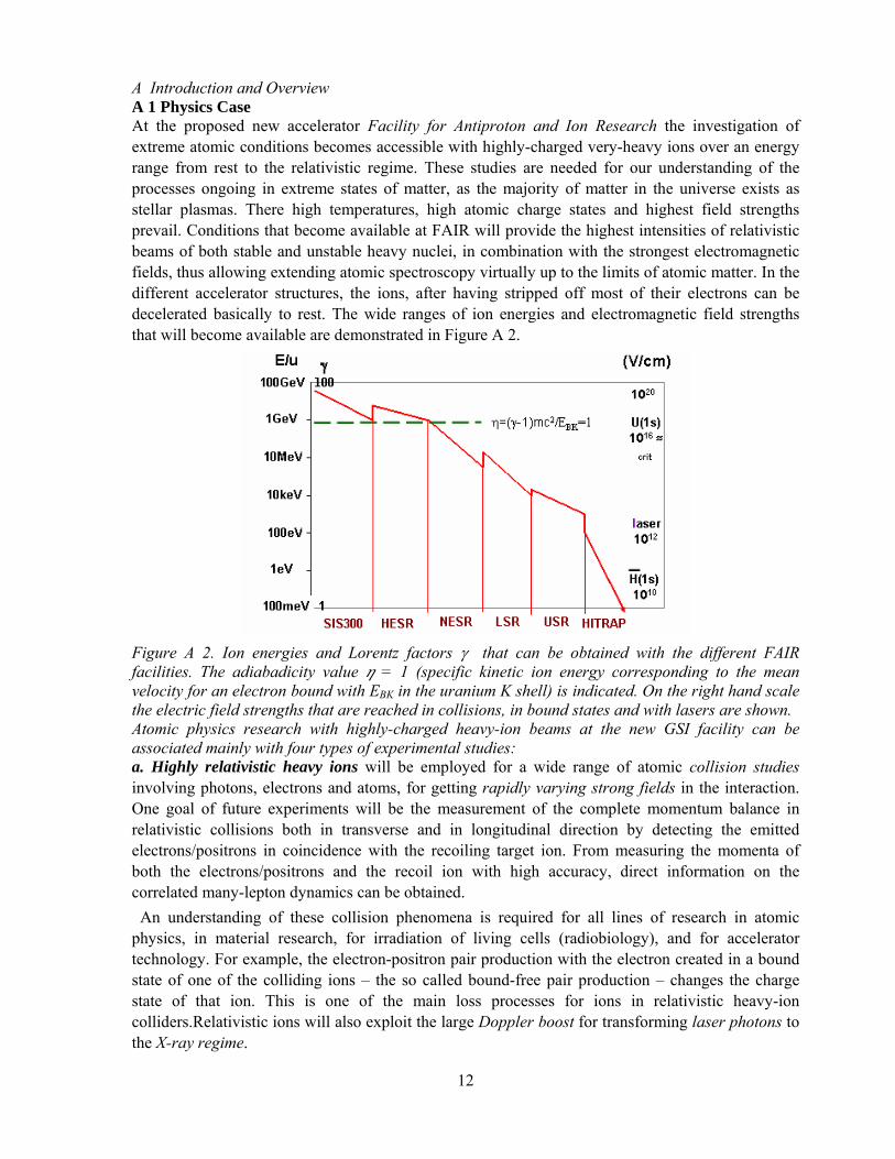
Figure A 2. Ion energies and Lorentz factors γ that can be obtained with the different FAIR facilities. The adiabadicity value h = 1 (specific kinetic ion energy corresponding to the mean velocity for an electron bound with EBK in the uranium K shell) is indicated. On the right hand scale the electric field strengths that are reached in collisions, in bound states and with lasers are shown. Atomic physics research with highly-charged heavy-ion beams at the new GSI facility can be associated mainly with four types of experimental studies: a. Highly relativistic heavy ions will be employed for a wide range of atomic collision studies involving photons, electrons and atoms, for getting rapidly varying strong fields in the interaction. One goal of future experiments will be the measurement of the complete momentum balance in relativistic collisions both in transverse and in longitudinal direction by detecting the emitted electrons/positrons in coincidence with the recoiling target ion. From measuring the momenta of both the electrons/positrons and the recoil ion with high accuracy, direct information on the correlated many-lepton dynamics can be obtained. An understanding of these collision phenomena is required for all lines of research in atomic physics, in material research, for irradiation of living cells (radiobiology), and for accelerator technology. For example, the electron-positron pair production with the electron created in a bound state of one of the colliding ions – the so called bound-free pair production – changes the charge state of that ion. This is one of the main loss processes for ions in relativistic heavy-ion colliders.Relativistic ions will also exploit the large Doppler boost for transforming laser photons to the X-ray regime.

13
b. High-energy beams will be utilized for achieving high stages of ionization up to bare uranium nuclei. Experiments will focus on structure studies for these ion species, a field being still largely unexplored. Despite the enormous success of QED in predicting the properties of electrons in weak fields, a precise test in the strong-field limit where novel phenomena might show up, is still pending. Accurate measurements of electron binding energies are very well suited to deduce characteristic QED phenomena in strong fields. Along with the precise determination of binding energies, measurements of the g factor of the bound electron in highly-charged ions provide a sensitive test of the magnetic sector of bound-state QED calculations in strong electromagnetic fields. It is planned to measure the g factor of an electron in the 1s-state of a hydrogen-like ion and in the 2s-state of a lithium-like ion. Thereby, it can be expected that the uncertainty of the nuclear size correction drops out and the full experimental accuracy can be exploited for QED tests with high precision. Dielectronic recombination (DR) of ions, having at least one electron, with free electrons turned out to be a novel and sensitive tool for precise structure studies. The possibility of producing highly-charged heavy ions and of storing and cooling them in a storage ring opened a new window for the investigation of the recombination of ions and electrons at low relative velocities. In this resonant process a free electron is captured and the excess energy excites one of the bound electrons to a higher state. The DR measurements provide information on both electron-electron interactions in the presence of a strong central field and on the ionic structure of the investigated species. In addition, new fields will be opened for these studies by the intensities of unstable nuclei that become available. c. Fundamental atomic physics studies and model-independent determination of nuclear properties with stable as well as radioactive atoms in well-defined charge states will be performed, applying atomic physics methods. An important scenario for this class of experiments will be the slowing-down, trapping and cooling of particles in the ion-trap facility HITRAP. In highly-charged ions precise calculations of the atomic structure can be performed. In addition, there are near-degeneracies of levels of opposite parity. The most advantageous situation probably occurs in heavy helium-like ions near Z = 64 and Z = 92, due to almost degenerated 2 3P0 and 2 1S0 states with opposite parity. In atoms with non-zero nuclear spin the hyperfine and weak quenching effects are mixed. This leads to an unusually large asymmetry of the delayed photon emission by polarized ions which can be measured in beam-foil type experiments. The potential of the new GSI facility for these studies is obvious since the energy splitting between the 3P0 und 1S0 states depends on the nuclear size and can be minimized by selecting the appropriate isotope. Thereby the parity violating effects can be amplified strongly. The prerequisite for this type of experiments is a polarized ion beam. Quite recently, promising schemes for the polarization of stored highly-charged ions and of the measurement of the degree of the polarization have been presented. This scenario will enable high-accuracy experiments in the realm of atomic and nuclear physics, as well as highly-sensitive tests of the Standard Model. d. Low energy beams of high-Z few-electron ions from an additional “low energy” storage ring (“LSR”) behind the NESR will be employed for collisions characterized by very large Sommerfeld parameters. In this domain of strong perturbations, the ionization mechanism is unclear. Experiments are essential to address the fundamental question of the nature of the ionization mechanism at threshold which is, surprisingly enough, still open. No perturbation theories are applicable and corresponding experiments will be best suited to test the predictive power of the most advanced ab initio theories. The combination of ultra-intense laser pulses and highly charged ions will open a completely unique field of research. In the strong electrical field created in the focus of ultra-high intensity

14
lasers, the Coulomb potential of atoms or low-charge ions is sufficiently depressed to allow bound electrons to escape over the potential barrier or to tunnel through it. This is not the case for heavy and highly-charged ions where the binding field strength is still much higher than the applied field-strength produced in the focus of the most intense present-day lasers. Distinctly different from the case of low-charged ions where the processes induced by the intense laser field saturate due to the onset of field-ionization, no such saturation is expected for highly-charged, high-Z ions. Consequently, high-Z ions will allow one to enter a completely new regime for the study of the interaction of intense laser fields with matter. A 2 Competitiveness At high, relativistic energies, the FAIR facility will be unique by providing the heaviest ions over a wide energy range from 1 to 30 GeV/u. In the special case of pair production there are very few and only inclusive measurements of pair production available in the intermediate relativistic regime of a few GeV/u. Here, even the target charge dependence is not well understood, whereas at extreme energies, in the region beyond hundred GeV/u, there is good agreement between theory and experiment. The new facility will be worldwide the only one capable of filling this important gap. Utilizing the high luminosity of the future GSI facility, beyond inclusive cross section studies also differential aspects of atomic processes at high energies become accessible, for which the electromagnetic interaction differs significantly from the low-energy regime. A measurement of the impact parameter dependence for both inner-shell ionization and excitation processes will enable the separation of the longitudinal and the transversal field contributions to the interaction. For such investigations, precise spectroscopy of photons as well as of electrons and positrons is required. The photon and electron emission gives the details of the specific excitation mechanism in those fields. One may also mention the possibility to search for recombination followed by e+-e- pair production instead of photon emission. This higher-order process, requiring high collision energies, is similar to dielectronic recombination, but with one electron being excited from the negative continuum into a bound state The new facility will provide intense beams of stable and unstable isotopes up to uranium at the highest charge states. At the NESR storage ring these ions can be stored and cooled at energies of 760 MeV/u down to 4 MeV/u and at the LSR even down to 0.5 MeV/u. For the low-energetic ions (below 100 MeV/u) the possibility to extract them into the dedicated low-energy Cave exists. These storage rings in their combination with the facilities installed have a decisive advantage over other experimental techniques as they allow to address fundamental process which become feasible at this time only in inverse kinematics: fully differential photoionization cross sections - including polarization - for the heaviest ions in arbitrary charge states, recombination, complete differential cross sections for the short wavelength limit of electron-nucleus bremsstrahlung and fully differential (e,2e) cross sections for ions by mapping the complete momentum balance of all emitted particles. Also, the combination of these very heavy, highly-charged ions with the low collision energies, where the Sommerfeld parameter q/v becomes very large, is an additional unique feature not available at any other machine. A singular opportunity is given by the combination of the SIS 12/100/300, the NESR storage ring and the PHELIX laser facility. In contrast to the typical experimental situation in gas targets, the storage ring provides precise control of the initial ion species and diagnostics of the final states of the ions and of ejected electrons on the single-event level. This will enable research at truly undisturbed single-ion condition, where the only interacting partners will be the laser field, the highly charged ion, and the detached electron.

15
The proposed FAIR facility with its intense heavy ion beams, in combination with novel experimental techniques such as excitation by X-ray or laser photons, mono-energetic electron beams, high-resolution spectrometers, or channelling in crystals gives world-wide unique opportunities for atomic spectroscopy. This will enable the exploration of the fundamental QED corrections to binding energies, magnetic moments, and the magnetic interactions in strong fields. The new accelerator complex at GSI will enable another important step by a large increase of the photon frequency range and by allowing spectroscopy for a wide variety of radioactive beams that is not available otherwise. The present limitations for the application of wavelength-restricted lasers will most certainly be widely removed. For instance, in the SIS300 ring the accessible transition energy range will be increased considerably due to a large Doppler shift. Spectroscopy in the NESR, although limited in the energy range, will be a key instrument for frontier experiments on highly-charged ions and radioactive isotopes. Furthermore, a completely new regime of laser cooling of heavy relativistic highly-charged ions can be opened. The HITRAP Facility where highly-charged ions can be brought practically to rest will be the only facility world-wide where bare U nuclei can be trapped in a strong magnetic field. The highly-charged ions will be cooled down to cryogenic temperatures. There the g-factor of a single electron bound in the potential of an arbitrary stable or unstable nucleus like 238U nucleus and others can be determined. Measurements of the hyperfine splitting (HFS) in hydrogen-like ions will give information about the distribution of the nuclear magnetization within the nucleus. By optical pumping within the HFS-levels of the ground state, the nuclear spins of radioactive nuclides can be polarized with high efficiency, opening unique possibilities to study questions of the Standard Model of fundamental interactions. Finally it has to be stressed that currently several heavy-ion beam factories are planned, or under construction or already in the commission phase worldwide. In the first line RIA (USA), MUSES (Riken, Japan) and HIRFL (Lanzhou, China) have to be mentioned in this context. Presently, traps but no ion storage-cooler rings are foreseen at RIA. Therefore, atomic physics experiments comparable to those planned for the NESR are missing there. The plans at MUSES and HIRFL in the realm of atomic physics, on the other hand, cover a rather similar spectrum. However, due to the comparatively low energies foreseen for these facilities, the achievable intensity of highly-charged heavy ions (e.g. bare uranium) should be there significantly smaller than that expected at the new GSI facility.
A 3 Experimental concepts and requirements Figure A 1 shows an overview of the different experimental installations of SPARC at FAIR. First we give here very short descriptions of these installations, and then list the different experimental requirements.
The following major installations will be developed and used by SPARC: SIS100/300: Laser cooling and spectroscopy installation that will mostly use Li-like very heavy ions. The set up exploits the Doppler boost of optical Laser photons in the rest frame of the counter-propagating ions to the XUV regime. High Energy Cave for AP/Biophysics/Materials Research: In this cave atomic physics experiments and applications in radiobiology, space and materials research with extracted beams from SIS12 or SIS100 will be performed. The investigation will concentrate on atomic structure (resonant coherent excitation) and collision studies at moderate and high-relativistic energies (ionization, capture, and pair production) as well as on irradiation of individual samples for biological or solid material research. New Experimental Storage Ring NESR – a “second generation ESR” New possibilities will be opened up by instrumentations such as the second electron target and the electron collider. The intense beams of highly charged, radioactive ions makes novel experiments possible. NESR is the "second-generation" ESR with optimized features and novel experimental installations. The NESR will serve also as an accumulator and storage/cooler ring both for ions and antiprotons.

16
Compared to all the other heavy ion storage rings currently under construction, the NESR will be the most flexible one, providing intense beams up to bare uranium. This warrants a leading position also with respect to other advanced projects. A large variety of experimental set-ups and installations for atomic physics experiments will be made here. For atomic structure investigations and QED tests the electron target, internal target, electron-, and X-ray spectrometers will be used. Recombination studies will be done with the specially designed electron target. Collision experiments are planned at the internal target with electron-, recoil-, and X-ray- spectrometers. FLAIR Building / AP Low-Energy Cave: This building is devoted to experiments with decelerated, low-energetic highly-charged ions and antiprotons. The experimental area will be served by the NESR. In the building, different installations (e.g. the Low-Energy Storage Ring LSR, the Ultra-low energy Storage Ring USR, and HITRAP) are located. From the LSR the ions can be actively slowed down, even to rest using the trap facility HITRAP. The installations will be shared with the FLAIR collaboration and for detailed descriptions of the LSR and USR see section I of this report and the FLAIR TR. The parameter requirements by the experiments:
Laser Spectroscopy and Laser Cooling at SIS100/300 needs Li-like and Na-like ions up to uranium with up to γ=30. For the spectroscopy part, the ion number is not critical, one could get results even for as little as 100 ions in SIS. High beam intensities are required for the cooling experiments. For interaction experiments of ultra-intense laser pulses with extracted bunches the AP or PP high energy caves might be used.
For Atomic Physics with Ion-Beams from SIS12/SIS100 to the low-energy AP cave the beam requirements are intensities of 109 ions per spill at 1 GeV and decreasing numbers to higher energies for radiation safety. A spill length of 1s and a beam spot of less then 10 mm on target is needed.
The Atomic Physics Experiments with Stored and Cooled Ions at the NESR have a variety of installations and projects with following requirements: The number of ions per cycle should reach 1010 at medium Z. The momentum spread after electron cooling is supposed to be less than 10-4. The beam energy should range from 760 MeV/u to the low energy limit, reached by deceleration to 3 MeV/u. Fast and slow beam extraction is needed. The lifetimes of stored ions are of utmost importance. Thus, an excellent vacuum of 10-11 mbar is needed.
The electron target should have an ultra-cold electron beam. The resulting energy spreads should be as low as a few 10 meV at collision energies below 1 eV and smaller than 5 eV at 100 keV. One should reach 300 keV in the center-of momentum frame.
Photon Spectrometer such as crystal spectrometers for soft and hard X-rays (3–120 keV), low-temperature calorimeter and Compton polarimeter will be installed. An Electron Spectrometer for electrons from 100 keV to MeV energy and an Extended Reaction Microscope for imaging recoils and slow and fast electrons in the range of meV should operate at the Internal Target.
For Atomic Physics with Cooled, Decelerated and Extracted Ions beams up to U with maximum intensity (typical 108 ions per spill) or lowest energy from NESR are transported to the FLAIR building. There one should get the ions down to 3 MeV/u into the AP Cave for collision and spectroscopy experiments. Additionally to NESR, ions can be slowed down in the LSR to 0.3 MeV/u. HITRAP is fed by ions up to bare uranium. Experimental investigation of highly charged ions, solid interactions, collisions, and X-ray spectroscopy will here be performed.
17
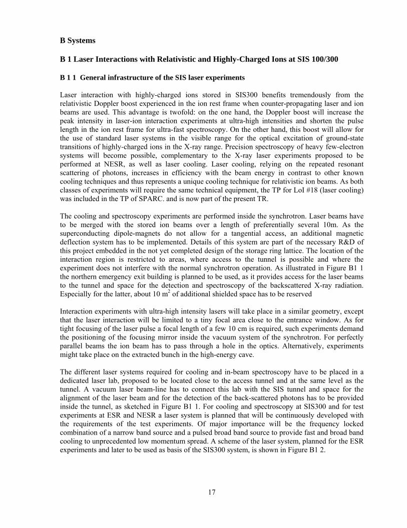
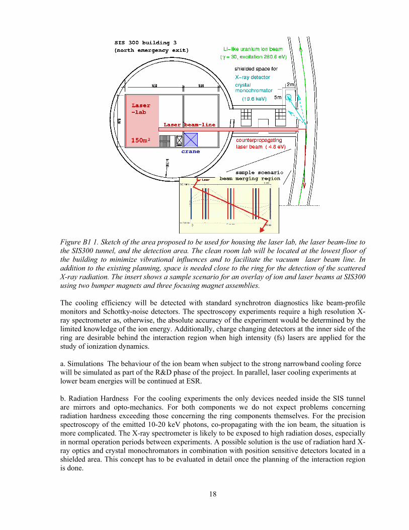
B Systems B 1 Laser Interactions with Relativistic and Highly-Charged Ions at SIS 100/300 B 1 1 General infrastructure of the SIS laser experiments Laser interaction with highly-charged ions stored in SIS300 benefits tremendously from the relativistic Doppler boost experienced in the ion rest frame when counter-propagating laser and ion beams are used. This advantage is twofold: on the one hand, the Doppler boost will increase the peak intensity in laser-ion interaction experiments at ultra-high intensities and shorten the pulse length in the ion rest frame for ultra-fast spectroscopy. On the other hand, this boost will allow for the use of standard laser systems in the visible range for the optical excitation of ground-state transitions of highly-charged ions in the X-ray range. Precision spectroscopy of heavy few-electron systems will become possible, complementary to the X-ray laser experiments proposed to be performed at NESR, as well as laser cooling. Laser cooling, relying on the repeated resonant scattering of photons, increases in efficiency with the beam energy in contrast to other known cooling techniques and thus represents a unique cooling technique for relativistic ion beams. As both classes of experiments will require the same technical equipment, the TP for LoI #18 (laser cooling) was included in the TP of SPARC. and is now part of the present TR. The cooling and spectroscopy experiments are performed inside the synchrotron. Laser beams have to be merged with the stored ion beams over a length of preferentially several 10m. As the superconducting dipole-magnets do not allow for a tangential access, an additional magnetic deflection system has to be implemented. Details of this system are part of the necessary R&D of this project embedded in the not yet completed design of the storage ring lattice. The location of the interaction region is restricted to areas, where access to the tunnel is possible and where the experiment does not interfere with the normal synchrotron operation. As illustrated in Figure B1 1 the northern emergency exit building is planned to be used, as it provides access for the laser beams to the tunnel and space for the detection and spectroscopy of the backscattered X-ray radiation. Especially for the latter, about 10 m2 of additional shielded space has to be reserved Interaction experiments with ultra-high intensity lasers will take place in a similar geometry, except that the laser interaction will be limited to a tiny focal area close to the entrance window. As for tight focusing of the laser pulse a focal length of a few 10 cm is required, such experiments demand the positioning of the focusing mirror inside the vacuum system of the synchrotron. For perfectly parallel beams the ion beam has to pass through a hole in the optics. Alternatively, experiments might take place on the extracted bunch in the high-energy cave. The different laser systems required for cooling and in-beam spectroscopy have to be placed in a dedicated laser lab, proposed to be located close to the access tunnel and at the same level as the tunnel. A vacuum laser beam-line has to connect this lab with the SIS tunnel and space for the alignment of the laser beam and for the detection of the back-scattered photons has to be provided inside the tunnel, as sketched in Figure B1 1. For cooling and spectroscopy at SIS300 and for test experiments at ESR and NESR a laser system is planned that will be continuously developed with the requirements of the test experiments. Of major importance will be the frequency locked combination of a narrow band source and a pulsed broad band source to provide fast and broad band cooling to unprecedented low momentum spread. A scheme of the laser system, planned for the ESR experiments and later to be used as basis of the SIS300 system, is shown in Figure B1 2.
18
Figure B1 1. Sketch of the area proposed to be used for housing the laser lab, the laser beam-line to the SIS300 tunnel, and the detection area. The clean room lab will be located at the lowest floor of the building to minimize vibrational influences and to facilitate the vacuum laser beam line. In addition to the existing planning, space is needed close to the ring for the detection of the scattered X-ray radiation. The insert shows a sample scenario for an overlay of ion and laser beams at SIS300 using two bumper magnets and three focusing magnet assemblies. The cooling efficiency will be detected with standard synchrotron diagnostics like beam-profile monitors and Schottky-noise detectors. The spectroscopy experiments require a high resolution X-ray spectrometer as, otherwise, the absolute accuracy of the experiment would be determined by the limited knowledge of the ion energy. Additionally, charge changing detectors at the inner side of the ring are desirable behind the interaction region when high intensity (fs) lasers are applied for the study of ionization dynamics. a. Simulations The behaviour of the ion beam when subject to the strong narrowband cooling force will be simulated as part of the R&D phase of the project. In parallel, laser cooling experiments at lower beam energies will be continued at ESR. b. Radiation Hardness For the cooling experiments the only devices needed inside the SIS tunnel are mirrors and opto-mechanics. For both components we do not expect problems concerning radiation hardness exceeding those concerning the ring components themselves. For the precision spectroscopy of the emitted 10-20 keV photons, co-propagating with the ion beam, the situation is more complicated. The X-ray spectrometer is likely to be exposed to high radiation doses, especially in normal operation periods between experiments. A possible solution is the use of radiation hard X-ray optics and crystal monochromators in combination with position sensitive detectors located in a shielded area. This concept has to be evaluated in detail once the planning of the interaction region is done.

19
Figure B1 2. Setup of the staged laser systems planned for the laser cooling experiments at ESR and SIS 300. Based on a UV wavelength of 257nm, a combination of continuous narrow-band and pulsed broad-band systems will be used for fast cooling with broad momentum acceptance to low final momentum spread determined by the narrow band system. c. Design Interaction Region Merging the ion beam and the laser beams over a straight section of al least several 10 m requires an additional deflection of the ion beam with one or two pairs of additional dipole magnets as depicted above. The design of this section will depend on the final design of the synchrotron lattice. Laser Systems It is planned to rely on commercial solid-state laser systems that can be adapted to the experimental requirements, supplemented by external frequency doubling units running at a UV wavelength of about 257nm. For cooling, a combination of a broad-band and possibly pulsed laser with a cw laser running at the same wavelength is planned. This laser system is based on the one used in current laser cooling experiments and will be further developed and tested at ESR and NESR experiments. For spectroscopic applications conventional pulsed lasers tunable over a wider range can be used. For ultra-high intensity laser interaction two different approaches have to be prepared: Experiments outside the ring in one of the high energy caves will utilize the PHELIX laser. For this scenario, laser cooling has to be used for the preparation of highest density bunches. Inside the ring, novel ultra-short pulse sources like the Munich LWS systems have to be used. These have to be developed together with MPQ/LMU Munich and other collaborators. Spectrometer An X-ray spectrometer with a resolution of typically 10-5 has to be developed, which will operate inside the tunnel behind the interaction region. It will most likely consist of a crystal spectrometer and a shielded detector. Particle Detectors
20
For the measurement of charge-changing processes and the determination of the trajectory of the ion beam, detectors have to be incorporated into the SIS300 design that are capable of detecting single ions. d. Construction Lasers The construction of the laser systems will start with prototypes in the laboratories of the responsible partners and is based on existing systems, that will be continuously improved in test beam-times at GSI. Spectrometer The construction of the spectrometer will be performed at a later stage by the responsible partners and it based on existing technology used at MAMI. e. Acceptance Tests and Milestones Laser Cooling Test experiments at ESR 2004-2007 SIS lattice simulations for overlap of ion and laser beam 2005 Simulations of laser cooled high-intensity highly-charged ion beams 2005-2006 Completion of the Cooling/Spectroscopy Laser System 2008 Installation and tests at SIS100 2009-2010 Laser Spectroscopy Test of X-ray detectors 2005-2007 Design of spectrometer 2007 Installation and tests at SIS100 2009-2010 Interaction with ultra-intense laser pulses Test experiments at highly charged low-energy ions 2005-2007 Test experiments at ESR energies 2006-2008 PHELIX beam line design 2007 Setup at the SIS100/300 site 2008-2010 Construction of ultra-fast laser 2009 f. Calibration The X-ray spectrometer will be calibrated by off-line measurements. g. Requests for Test Beams For a continuous development of the laser systems and the cooling technique, beam times with Li-like ions of about 2 x 2 weeks at the low-energy storage rings (ESR, NESR) and at the HHT cave at SIS 12 /SIS 100 for high intensity experiments are required. With respect to laser spectroscopy additional 2 x 2 weeks at the low-energy storage rings (ESR, NESR). B 1 2 Trigger, DACQ, Controls For all pulsed laser-ion interactions, a phase-sensitive synchronisation with the circulating ion bunch and the laser pulse is mandatory. Concepts for this synchronization with short pulse lasers are currently developed in the context of the PHELIX project and are well-known from ESR laser experiments. However, as the pulse structure of the synchrotron is given, the necessary R&D is on the laser side and can be performed off-line.

21
B 1 3 Beam Requirements a. Beam specifications For the laser-cooling and in-beam spectroscopy beams of Li-like and Na-like heavy ions are required at relativistic energies, samples are given in the LoI#18 (laser cooling). Additionally, hydrogen-like ions and other charge states will be required for interaction studies with ultra-short, ultra-intense lasers. The beams have to be bunched at variable bucket depth and energy; yet, no unusual beam properties are required. For proof-of-principle cooling experiments and spectroscopy experiments low currents are sufficient, yet there is no upper limit. Merging the laser and ion beams is a crucial issue so that control over the ion beam position on a 0.1mm and sub-mrad scale is mandatory within the interaction region.
20 40 60 80 1000,0
0,1
0,2
0,3
0,4
0,5
0,6
0,7
fra
ctio
n
stripper thickness (mg/cm2)
bare H-like He-like Li-like Be-like B-like C-like N-like O-like F-like
uranium => carbon; 500 MeV/u
Figure B1 3. Calculated charge state distribution for initial uranium 28+ ions at 500 MeV/u penetrating through a carbon stripper foil. For a foil thickness of about 40 mg/cm2 the yield of Li-like uranium ions reaches its maximum. The same calculations were performed for the design of the current carbon stripper foils at the ESR. Here, for Li-like uranium ions at 400 MeV/u yields of about 40% have been obtained. The stripping of the heavy ions into Li-like charge states has to be performed behind the synchrotron SIS 12 and care has to be taken not to strip off all electrons. For a uranium sample energy of 500 MeV/u the charge state distribution is calculated for a variable stripper thickness in the following graph (Figure B1 3), showing a good efficiency for the desired charge-state. b. Running Scenario A typical experiment will require 1 to 2 weeks of beam time. A combination of cooling and spectroscopy experiments might be practical. The laser cooling experiments will require a number of beam times at different lithium-like ions for optimisation. The aim of the spectroscopy experiment is to cover lithium-like ions across the chart of nuclides, and to determine isotopic effects between stable isotopes. It is anticipated that other experiments will use laser-cooled beams (plasma physics, interaction with ultra-intense lasers etc.). Therefore, at least 2 to 3 beam times per year are envisioned. B 1 4 Physics Performance Laser cooling of highly charged ions in the SIS300 holds the promise of producing ultimate beam quality in terms of momentum spread, emittance and phase-space density. Even beam crystallisation might become possible due to the favourable lattice symmetry of the synchrotron. Especially for

22
experiments at the luminosity limit, like the investigation of nuclear effects due to the interaction with well focused, ultra-intense laser pulses, this combination will considerably facilitate the planned experiments. The efficiency of laser cooling of highly charged heavy ions increases with the beam energy due to the relativistic Doppler shift and the associated photon momentum transfer, and the faster electronic transitions of highly charged ions, as pointed out in detail in LoI #18 (laser cooling). For the sample ion 238U89+ the cooling time for a reduction of the relative momentum spread of 10-4 will be of the order of 1-10s, depending on the available laser power and laser line-width. The final momentum spread that can be reached will strongly depend on the intrinsic heating mechanisms, that have to be numerically studied and compared to the planned test experiments. In principle, a relative momentum spread of the order of 10-8 can be reached due to the width of the transition. For laser spectroscopy of Li- and Na-like ions it has to be pointed out, that the complete periodic system can be investigated at SIS300. Already with uncooled ion beams (momentum spread 10-4) the accuracy of the transition energies can be systematically increased by at least one order of magnitude. Due to the high revolution frequency of the ions, the high excitation probability when using a conventional pulsed laser as also planned for the cooling, and the complete solid angle for the detection in forward direction, a count rate on the X-ray detector of little less than 1 Hz can be expected for single ions. Recording a full spectrum will take of the order of one hour for only some 10 ions. Thus, for stable isotopes, count rate should not be any problem. Moreover, the precision spectroscopy will yield precision information about the beam energy. The interaction of ultra-short pulses with relativistic beams will benefit two-fold by the relativistic velocity: the interaction time in the internal reference frame is shortened by a factor γ, and , at the same time, the energy of the photons is increased by the same factor. The effect on the pulse length by more than one order of magnitude represents an important qualitative factor in atto-second applications. The same is true for the increase of the photon energy. The resulting increase of the interaction intensity will allow the use of smaller lasers or can be utilized to reach into an intensity regime that otherwise is not attainable within the technical limits.

23
B 2 Atomic Physics with Ion Beams from SIS12/100 B 2 1 The High-Energy Atomic Physics Cave The experiments in atomic physics and applications in radiobiology, space and materials research with extracted beams from SIS 12 or SIS100 will be performed in the new "High-energy Atomic Physics Cave". The investigation will concentrate on atomic structure and collision studies at moderate and high-relativistic energies as well as on irradiation of individual samples for biological or solid material research. In addition, it is planned to test the radiation sensitivity of large electronic components (e.g. microprocessors) of space crafts, and to calibrate detector systems for cosmic radiation studies. The details of the experiments in radiobiology and space and materials research are described in the "Letter of Intent for Applications of Relativistic Ions in Radiobiology and Space Research" and in the "Letter of Intent for Materials Research". The Materials Research LoI proposes the study primarily of two subjects: (1) Heavy ion-induced modifications of solids that are exposed to extremely high pressures, and (2) Analysis of material modifications induced by relativistic heavy ions. As a further topic (3) Desorption caused by beam-wall interactions is added. Experiments concerning this subject could be useful, since it is open whether all problems related to rest-gas generation by intense high-energy beams will be solved when FAIR has started to operate. In the present Technical Proposal we will discuss only the atomic physics aspects of the planned high-energy experimental area, while those of the closely related experiments in radiobiology, space, and materials research will be presented in a separate TR. The overall properties of the cave, which is shown schematically in Figure B2 1 will be very similar to those of the existing Cave A at SIS 12. It is to note that the linear dimensions given are only preliminary.
Figure B2 1. Schematic graph of the experimental area for atomic physics, materials research and biophysics using beams from SIS12/100. B 2 1.1 The Charge State Spectrometer For atomic physics experiments with highly-charged, few-electron ions the cave will be equipped with a charge state spectrometer allowing for charge state separation behind a reaction target for beam energies up to about 1 GeV/u (≈ 20 Tm). For this purpose, beside a beam line from SIS100 also a direct beam line from SIS12 to the cave has to be installed. The current experimental program in Cave A has shown, that life-time measurements and experiments on precise photon and electron spectroscopy and on channelling strongly profit from coincidence measurements with the final projectile charge state. Here, beam intensities of up to 108 ions/spill with spill lengths of the order of 1 sec are required. Recent calculations have shown that at such intensities the dimesnions of the radiation shilding will be compareable to those of the existing Cave A.

24
For atomic physics experiments at even higher beam energies of up to ≈ 10 GeV/u, e.g. resonant coherent excitation using channelling techniques and investigation of different channels for pair production, no charge state separation is foreseen and the desired beam intensity amounts to 108
ions/spill. a. Simulations Ion-optical calculations for the charge state spectrometer are still going on. It is planned to operate the spectrometer at ion energies up to about 1 GeV/u (≈ 20 Tm). Also at this energy it should be possible, to separate bare, hydrogen-, helium-, and lithium-like U ions. Preliminary ion-optical calculations show that a momentum dispersion of about 10 mm/% is sufficient for the separation. b. Radiation Hardness does not apply
c. Design For the design of the cave and of the spectrometer it is important to consider the needs of other experiments in the cave, especially of the biophysics/space and materials research behind the spectrometer and of channelling experiments in front of it. Since irradiations of larger samples are planned, sufficient space for a magnetic scanner has to be reserved. In the design also sufficient space for the power supply of the quadrupoles and the dipole has to be foreseen. The dispersion needed can be achieved by a combination of a quadrupole doublet and a dipole magnet. Since the FRS will be demounted in the next years, an optimal solution with regard to dispersion and costs would be the use of existing quadrupoles and a 30° dipole magnet from the FRS which have a dispersion of 25 mm/%. In addition, the dipole magnet can be equipped with a vacuum chamber allowing for straight passage to the biophysics/space and materials research area. Detailed ion-optical calculations have to be performed in order to find the best possible arrangement. d. Construction The charge state spectrometer will be provided by GSI. e. Acceptance Tests does not apply f. Calibration Calibrations of charge state will be done with beam, starting from selected bare ions. g. Requests for Test Beams Commissioning of the spectrometer (in total about 2 weeks). B 2 1.2 Resonant Coherent Excitation in Crystals at Relativistic Energies When an ion is channeled in a crystal, it is exposed to a periodic excitation in the screened Coulomb field of the aligned atoms of the target. Resonant Coherent Excitation (RCE) can occur if the frequency of this excitation matches the frequency of an internal electromagnetic transition f via the following relation (axial channeling) f = k γv/d, where γ is the Lorentz factor, v the ion velocity, d the inter-atomic distance along the considered axis, and k an integer number. The high-energy cave offers excellent conditions for a high resolution goniometer set-up for resonant coherent excitation (RCE) studies of atomic and nuclear levels in beams with relativistic energies from SIS100; the location provides for well collimated beams a long drift distance following the charge separating dipole magnet (Figure B2 1 ).

25
Figure B2 2. Transmitted fraction of Ar 17+ ions [Na03] Atomic RCE has been studied in crystal channeling conditions, which has lead to extensive work by several groups in the world [Az03]. One remarkable outcome of these experiments is the high-resolution spectroscopy that can be achieved in the measurement of the transition energies, and their perturbation by the static electric field felt by an ion inside ordered matter. In the following we distinguish the two proposals nuclear RCE and atomic REC. Nuclear Resonant Coherent Excitation With the beam energies available in the high-energy cave, one can reach the resonance energies for the first excited level of 238U (∆E=44.9 keV), which gives for the <111> axis of tungsten (d=2.74 Å): Fundamental k=1: E=8.36 GeV/u k=2: E=3.78 GeV/u k=3: E=2.29 GeV/u The first excited level of 238U is one example among the possible candidates. The principle of this experiment is quite simple: One measures de-excitation gamma emission, in coincidence with the transmitted nucleus, as a function of the incidence energy and crystal orientation. For this part of the channeling program, the high energy cave could be used, without using the charge analysis magnet. Atomic Resonant Coherent Excitation The methods used for these investigations are:
• Channelling of relativistic heavy ions and observation of a decrease of the charge state survival fraction in resonance with an atomic excitation.
• Observation of characteristic X-ray emission when a resonance with an atomic excitation is hit.
It is seen that at 10 GeV/u Pb81+(1s) the electron can be excited from the 1s to the 2p state with the third order resonance. For exciting 1s to the 2p of U91+(1s) at 10GeV/u, one needs the 4th order resonance.
a. Simulations Concerning high energy channelling: critical angles for channelling at relativistic energies are of the order of 10-4 rad. Thus the incoming beam angular divergence should be smaller. If the beam extracted from SIS100 does not match this condition, this requires a set of slits in the transfer beam

26
line from SIS100 to the high energy cave, which could allow one to reach the following conditions at the target: 1. A beam spot size of 5 mm radius or less. 2. An angular divergence much smaller than the critical channelling angles (typically one needs
rms values of less than 10-4 rad in x and y to perform reliable atomic and nuclear RCE).
b. Radiation Hardness From experiments in the existing Cave A and at the FRS it can be concluded that up to energies of about 1 GeV/u radiation will cause no damage of the detectors. The situation at higher energies has still to be investigated. Uranium with fluxes in the order of to 109 particles per spill irradiations of the crystal may occur. Sample moving techniques may have to be used for long-time irradiations.
c. Design For reaching the requirements of the beam angular spread, it may be necessary to set the slits separated by about 100 m, without focusing devices in between. Also, the beam monitoring is essential for such experiments. Beam profilers should be placed inside the high energy cave: one as close as possible to the target, a second one at the end of the beam line at 0°, and a third one at the end of the deviated beam line. The Riken group can provide the following channelling chamber and the goniometer:
Figure B2 3. A schematic drawing of the high precision goniometer. d. Construction The high-precision goniometers required for crystal alignment will be provided by the collaborating groups from Lyon (IN2P3, France) and Tokyo (RIKEN, Japan). e. Acceptance Tests does not apply f. Calibration does not apply g. Requests for Test Beams Commissioning of the goniometers (in total about 2 weeks).
27
B 2 1.3 Pair Production and Electron Capture in Relativistic Atomic Collisions In the high-energy cave it is planned to measure free multiple pair production up to energies of 10 GeV/u, the vacuum capture process through pair production (ECPP) up to around 1.3 GeV/u and di-electronic capture by pair production (DECPP) at around 1.2 GeV/u. We plan the following experimental schemes: The cross section for DECPP is proportional to the target atomic number ZT, similar to radiative electron capture. In contrast, it should have a clear resonance behaviour. We estimate that it should be observable in an U92+ - fixed target collision experiment at Ekin º 1.2 GeV/u. It should clearly show up as double electron capture accompanied, by the emission of a positron. The width of the peak is given by the Compton profile (assuming that the momentum of the emitted positron is fixed). With the same set-up we can measure the ECPP cross section by selecting single capture in coincidence with an emitted positron. For determining capture into excited states, we plan to measure capture in coincidence with characteristic X-rays pf the projectile. For detecting multiple pairs with high efficiency, the target recoils should be analyzed together with multiple positrons, or multiple electron-positron pairs. So far, the collaboration could not identify the most suitable double-lepton spectrometer, that covers a large momentum band simultaneously. It is our intention to investigate the different options further for finding the most efficient solution. a. Simulations In the following we give some count rate estimates for different processes described above: In a first step we plan to use solid targets for high target electron density, and to measure
+++ +→+ eUCU 9192
+++ +→+ eUZU T
9192
−+++ ++→+ eeUZU T9192
in coincidence, and as function of the target thickness. With 1.2 GeV/u U92+ ions the following cross sections are estimated by interpolation between measured and calculated values [Ru93,Va92,Be97,Va97,Kr98,Va00,Ar03]:
σREC σDECPP σECPP σNRC σION C target 26 barn 40 µbarn 600 µb barn 3 mb barn 100 b barn Au target 340 b 500 µbarn 1.4 barn 1000 barn 10 kbarn
where σREC is the radiative capture cross section, σDECPP is the di-electronic capture by pair production, σECPP is the vacuum capture cross section, σNRC denotes the non-radiative, and σION the K-electron ionization cross section. With a beam intensity of 107 s-1 and target thickness of 1019 cm-2-1021 cm-2 and the above estimated cross sections one can expect the following count rates (detection efficiency close to 100%):
C target: 160 −≈ sdt
dN ECPP 14 −≈ sdt
dN DECPP
Au target: 11400 −≈ sdt
dN ECPP 15.0 −≈ sdt
dN DECPP

28
b Radiation hardness The high-energy cave is designed for taking 109 ions per spill at 1 GeV/u and less for higher energies, according to radiation shielding requirements. The charge state spectrometer and detectors as well as other experimental instruments will be able to handle this irradiation. The targets are usually very thin and the count rate is low (see above). c Design The experiments will use the standard installations in the high-energy cave. The charge spectrometer has to allow charge-state separation up to 1.3 GeV/u. X-ray detection systems will be available (see B3 ). The design of the recoil and e+-e- spectrometer needs still to be done. Several concepts were discussed, however, the most suitable scheme is not found yet. d. Construction The construction of the e+-e- spectrometer is planned to be started in 2006. e. Acceptance test does not apply f. Calibration The calibrations of X-ray detectors, recoil and e+-e- spectrometers will be done at every run. B 2 2 Trigger, DACQ, Controls, On-line/Off-line Computing The existing acquisition system at GSI satisfies the requirements for the relatively simple channeling experiments with a few X-ray detectors at the target, and the detection of transmitted particles. The system is also sufficient for experiments with the spectrometer, in which typically atomic lifetimes in a beam-foil arrangement and energies of X-rays or electrons for precise spectroscopy are measured which strongly profit from coincidence measurements with the final charge state of the projectiles.
B 2 3 Beam/Target Requirements From the experiments with the magnetic spectrometer presently installed in Cave A it can be concluded that the beam spot on target should be ≤ 1 cm at intensities of up to 109 ions per spill with a spill length of about 1 sec for coincidence experiments. The channeling experiments have the strongest requirements to beam quality: beam spot size <1cm, angular divergence <10-4 rad, intensity >106 ions/s. Stripper foils in front of one of the bending magnets of the beam pipes between SIS12/100 and the cave are necessary for choosing the desired charge state of the incoming ions. Atomic RCE may require planar channeling conditions with fixed energy. Nuclear RCE may require axial channeling with varying energy. The pulse length should be as long as possible.

29
B 2 4 Physics Performance 4.1. Nuclear Resonant Coherent Excitation So far nuclear RCE has never been observed. One reason is the much weaker probability for Coulomb excitation of a nucleus than for an electronic transition. Another reason is that very high ion energies are required to excite the first levels on a stable nucleus, that are at least above ten keV. With the intense, high-energy heavy-ion beams, the FAIR facility at GSI will provide a unique opportunity to explore nuclear RCE. From a fundamental point of view, exciting a nucleus by the virtual photons of a periodic crystal lattice is complementary to laser excitation. The excitation strength at the resonance can be studied in detail as a function of impact parameter inside the crystal channels. This method could open interesting perspectives concerning in-flight spectroscopy of exotic nuclei at the super fragment separator. 4.2. Atomic Resonant Coherent Excitation The high accuracy and resolution that can be reached makes this method to a crystal-assisted virtual photon spectroscopy with relativistic heavy ions. Due to the high energies available in the high-energy cave, atomic excitations of the 1s electron up to H-like U can be reached in higher harmonics of RCE. The following physical issues are of importance: 1. Channelling and semi-channelling of relativistic heavy ions, where the crystal field behaves like mono-energetic virtual photons. 2. High resolution virtual photon spectroscopy of a few electron heavy ions with a precision of ppm. 3. Observation of Rabi oscillations with the intense virtual X-rays.
Figure B2 4 shows the kinetic energies for the different orders of the resonant 1s – 2p transitions in Si <110>.
Figure B2 4. Resonance energies of 1s-2p transitions for 1st (purple), 2nd(blue), 3rd(light blue), 4th(green), 5th(orange), and 6th(red) order. It is seen that 30GeV/u U91+(1s) can be excited from the 1s to the 2p state with the first order resonance. 4.3. Pair Production and Electron Capture in Relativistic Atomic Collisions In peripheral collisions of high-Z systems at sufficient high energies, huge transient field pulses are generated that lead to large cross section for production of free electron-positron pairs. The

30
transverse electric and magnetic components of the electromagnetic fields associated with the moving ion charge increases steadily with γ. With U beams from SIS100 with γ =10 field strengths of 1018V/cm, far above the critical Schwinger field strength, are reached.
Figure B2 5. Schematic view of the di-electronic capture by pair production (DECPP). Capture from pair production, the so-called vacuum capture process, ECPP, increases, in contrary to all other capture mechanisms, with beam energy. At sufficient high energies it is the dominant capture mechanism [Ru93.Kr98]. There are ongoing efforts to understand the pair production and capture process, particularly in the ‘non-pertubative regime’. This regime is at energies below approximately 20 GeV/u and high projectile and target nuclear charges. The non-pertubative regime is mainly caused by effects from combined charge of projectile and target. This leads diving of the most strongly bound energy levels into the negative continumm. At small impact parameters also multiple pair production should occur with high probability. The unitarity rule could be violated and multiple pairs would be direct experimental signatures for the non-pertubative character of the pair production. Occurrence of multiple pairs would also largely influence the ECPP cross section. There has been an extensive debate on the role of capture into excited states [Be97, Va97, Kr98, Va00]. This question is not solved yet by a direct measurement. Capture into excited states and multi-step ionization via exited states can become an important contribution to the cross section at energies between 1-10 GeV/u.. An additional process can occur where two electrons are captured quasi-resonant, by exciting the negative continuum to emit a positron (DECPP, Figure B2 5). The captured electron provides the energy for pair formation. It is analog to the ‘negative-continuum dielectronic recombination’ proposed by Artemyev et al. recently [Ar03]. That process can enhance the vacuum capture cross section additionally and is highly non-pertubative. Its first detection can be possible with the charge separator in the high-energy cave.

31
B 3 Atomic Physics Experiments with Stored and Cooled Ions at the NESR B 3 1 Experimental Installations
The New Experimental Storage Ring NESR with its instrumentation for atomic physics experiments is shown in Figure B3 1. The NESR can be supplied with highly-charged heavy ions from SIS 12 and with exotic nuclei from SFRS. At the gas jet target ion-atom reaction mechanisms as well as the ionic structure will be studied; beyond X-ray spectroscopy, 0-degree electron spectroscopy, recoil-ion-momentum spectroscopy, and laser spectroscopy will be applied here. At the electron target the atomic assisted electron-electron interaction will be studied. Here also laser techniques and X-ray spectroscopy will support the experiments. At the electron collider electron pulses will interact head-on with laser pulses producing forward emitted X-ray pulses. Moreover, the highly-charged heavy ions can be decelerated in the NESR down to the MeV/u region and extracted toward a fixed target area. There, atomic reactions with highly-charged ions at low velocities will be performed; also here X-ray spectroscopic and laser techniques will be applied. In the HITRAP facility attached to the fixed target area the ions can be decelerated down to almost rest and captured into a trap system for precision measurements.
Figure B3 1. The New Experimental Storage Ring NESR with its instrumentation for atomic physics experiments.

32
B 3 1.1 Electron Target (Second Electron Cooler) The NESR will be equipped with a dedicated ultracold electron target for precise electron-ion collision studies. It will be operated independently from beam cooling tasks and will be optimized with respect to high resolution and sensitivity. The target will be located in straight injection section of the NESR (Fig, B3 1).
Figure B3 2 Schematical drawing of the electron target. The electron beam is produced by a thermal cathode. In order to obtain ultracold electrons in the interaction section the beam is adiabatically expanded and adiabatically accelerated. Purpose of the Equipment: The main advantages of a dedicated electron target at NESR are fourfold: 1. Improvement of the resolution and of the sensitivity of dielectronic recombination (DR)
measurements: During the measurements, the energy and the energy spread of the ion beam are kept in a narrow range by the main electron cooler at NESR. This improves the energy resolution and the precision at high DR energies. Additionally, the new cooler will be equipped with adiabatic expansion and adiabatic acceleration. In other words, both the transversal as well as the longitudinal temperature of the electrons will be significantly lower than those of the presently available electron cooler. This leads to a strongly improved resolution both at low as well as at high relative electron energies in the c.m. system, and thus to better signal to noise ratio. It also allows for measurements of DR resonances with sub-eV energies, for which the sensitivity of the system is extremely high.
2. It makes possible DR measurements of high-energy transitions: Such measurements are not possible with one cooler, since it is not possible to swiftly and precisely ramp the cooler voltage up and down between potentials that have to differ by more than 100kV. As mentioned earlier, measurements of KLL, KLM KLN, and higher DR-resonances in H-like uranium will push open a new window of opportunities to study QED-interference effects of overlapping resonances.
3. Low-energy second electron cooler for decelerated heavy ions: For measurements that will need decelerated ions stored in the NESR or extracted low energy beams, as for instance FLAIR or AGATHA, the availability of an additional electron cooler at low energies shortens significantly the deceleration and/or extraction cycles.
4. Improvement of the duty cycle of DR measurements: Without a dedicated electron target a DR measurement has to use a cooler for a short period of time as a target followed by a short period of time for cooling. The duty cycle of the measurement is usually ≤ 50% and the ion beam is not cooled during the measurement. With a dedicated electron target, a separate electron cooler cools the ion beam continuously, and the DR measurements are performed at the electron target

33
with nearly 100% duty cycle. This also shortens the time needed to study short-lived radioactive isotopes.
Basic requirements: Based on the experience, R&D and tests of the present equipments available at ESR, SIS, TSR (both electron cooler as well as electron target), CRYRING and—last but not least—in Novosibirsk (including the electron cooler built for Lanzhou) the basic requirements and specifications of the NESR-electron target will be as follows: (i) Requirement for the stability of the main NESR electron cooler at lower voltages: A feasibility study for a cooler in the energy range between 2 and 450 kV is being performed in Novosibirsk. For DR experiments at low relative velocity differences, the stability of the main cooler at energies as low as 20-30 kV is of great importance. The NESR main cooler group will be contacted in this matter. (ii) The maximal sustainable high voltage of the electron target needed is 40 kV. (iii) The final beam size as well as the electron current will be tunable. This will be accomplished by (i) different ratios of the B-fields in the gun section and in the solenoid section and (ii) different settings of electron extraction and acceleration voltage. This offers high flexibility to optimize the electron beam parameters to the requirements of individual experiments. (iv) The envisaged maximal electron current is 1 A. The Heidelberg group will check whether this requirement does not conflict with the required adiabatic acceleration and—more general—with the required low temperature of the electron beam. A reduction by a factor 2 (or more?) might be necessary. (v) The envisaged (maximal) diameter of the electron beam is 3 cm. Similarly as in (iv) this value has to be checked. A possible reduction of it below 2 cm might result in difficulties for the breeding of additional charge states in the ring and/or for simultaneous measurements of two stored isotopes or nuclides. (vi) The maximal solenoid field required is 0.2 T. Such a relatively high magnetic field is necessary to minimize the energy transfer between transverse and longitudinal electron motion. This value should be communicated to Peter Beller and to the NESR crew. (vii) The planned adiabatic expansion of the guiding magnetic field by a factor of 20 would lead to transversal temperatures of T⊥ ≅ 5 meV. From this, and from the previous requirement, it follows that a superconducting magnet for the gun section with a max. B-field of 4 T is needed. Presently, it is not clear whether values below 2-3 meV are feasible under realistic conditions. A photo cathode is an option not included in the present planning. (viii) Longitudinal temperatures of T|| ≅ 0.01 – 0.03 meV after adiabatic acceleration are envisaged. Such low temperatures might require a reduction of the maximal electron current. The length of the acceleration section is not fixed yet. The available space in the building will probably require that the length should not exceed 5 m. The question how to minimize the length will be investigated. (ix) The radius of curvature should be as large as possible in order not to heat the electron beam in the toroid section. The available space in the building will also make it necessary to keep it below 2 m. This has to be investigated as well. (x) A length of 4 m for the solenoid (interaction) section is envisaged for better luminosity. This seems to be feasible if the toroid radii are below 2 m. The place available for the electron target will apparently be in the injection section of NESR. (xi) A linearity of the straight section of better than 0.1 mrad seems to be feasible. (xii) The ion beam has to be parallel to the electron beams in the cooler and in the electron target. (xiii) Diagnostic tools for the electron and ion beams in the electron target and in the cooler are needed. (xiv) Previously, a horizontal bending plane for the electron beam has been discussed. The difficulties introduced by such a solution to the injection of the ion beam have been discussed. It was decided to have a vertical cooler. An additional tower will be needed for the gun section. (cf. (viii) and Figure B3 2.
34
(xv) The requirement to have both co-propagating as well as counter-propagating electron and ion beams has been dropped. With a main cooler set at 400 kV, the energies needed to study high-energy dielectronic-recombination resonances are attainable in co-propagating geometry. Experiments that require higher energies (and, thus, counter-propagating beams) could be performed under more favorable conditions at the electron collider (high energy) or at the gas jet target (high luminosity). a. Simulations The design and the construction of the electron target follow standard patterns of ion-optical calculations, high-voltage and magnet design. Presently, simulations are being planned for the gun section in order to optimize the electron current and for the toroid section in order tostudy the heating of the electron beam and the influence of the toroid radius at high energies. The simulations will be accompanied by measurements at TSR electron target in Heidelberg. For instance, the influence of the extraction voltage on longitudinal electron temperature will be studied experimentally with the TSR electron target outside the storage ring with an installed energy analyzer. Milestones are (i) the final specification of the maximal electron current and (ii) the final design value for the toroid radius. The second task will be accomplished in the next months, the first one-this summer. i. of the detectors The particle detectors are of utmost importance for the envisioned experiments. In order to simulate the spatial distribution of particles that have captured an electron both the ion optics as well as the available space in and after the dipole sections of the ring have to be known in detail. The simulations will be performed in close collaboration with the NESR accelerator group. Additionally, simulations for beam intensity monitors based on the ionization of the residual gas will be performed and accompanied by experiments in Lanzhou. ii. of the beam After the ion optical details of the NESR are known in detail, the questions to be addressed are mainly the stability and the temperature of the ion beam when the cooling energy is in close proximity to the electron target energy. Additionally, the problem of having breeding higher charge states and of investigating cocktail beams will be tackled. Scenarios for recycling of charge state after an electron capture by bunching, accelerating, stripping of an electron in the gas jet, and deceleration are to be considered as well. b. Radiation Hardness The radiation hardness of the particle detectors is of utmost importance. The cooling suppressed dilatation of the ion beam leads to extremely high particle fluences and poses, thus, a special challenge to the radiation hardness. Gas-filled chambers, diamond detectors, and glass scintillator detectors will be used. The channel plates of the residual gas monitors are not radiation hard and must not be exposed to a direct beam impact. The electrodes of the electron beam position monitors and especially their vacuum feedthroughs would not sustain a direct hit of the full electron beam current and have to be protected.It is not planned to use special radiation hard electronics. Based on the ESR experience, no particular precaution for standard electronics is needed. This holds both for the data acquisition modules as well as for the slow controls. Data from and to electronics on a HV platforms will be transmitted via light pipes. Special care has to be taken for electronics in the vicinity of strong magnetic fields, especially if fast ramping is planned.The same holds for the other electrical components nearby. It is important to have the HV supplies as close as possible to the recipients in order to minimize the capacitance of the cable connections. c. Design
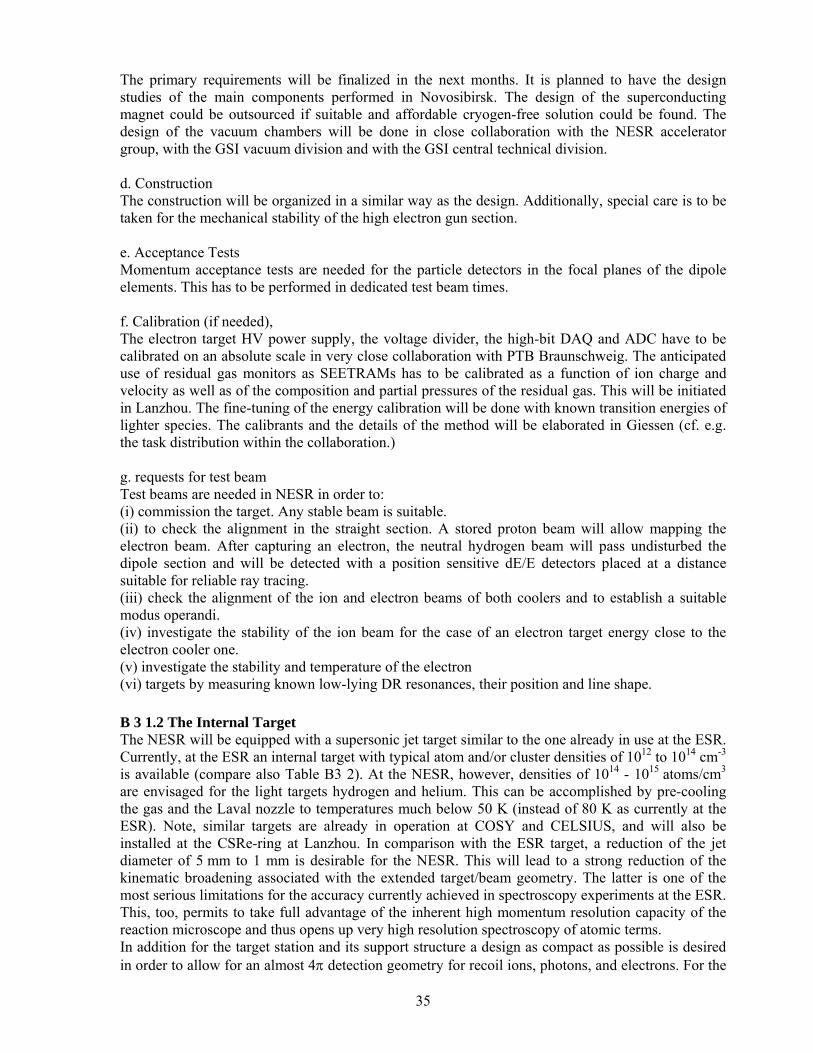
35
The primary requirements will be finalized in the next months. It is planned to have the design studies of the main components performed in Novosibirsk. The design of the superconducting magnet could be outsourced if suitable and affordable cryogen-free solution could be found. The design of the vacuum chambers will be done in close collaboration with the NESR accelerator group, with the GSI vacuum division and with the GSI central technical division. d. Construction The construction will be organized in a similar way as the design. Additionally, special care is to be taken for the mechanical stability of the high electron gun section. e. Acceptance Tests Momentum acceptance tests are needed for the particle detectors in the focal planes of the dipole elements. This has to be performed in dedicated test beam times. f. Calibration (if needed), The electron target HV power supply, the voltage divider, the high-bit DAQ and ADC have to be calibrated on an absolute scale in very close collaboration with PTB Braunschweig. The anticipated use of residual gas monitors as SEETRAMs has to be calibrated as a function of ion charge and velocity as well as of the composition and partial pressures of the residual gas. This will be initiated in Lanzhou. The fine-tuning of the energy calibration will be done with known transition energies of lighter species. The calibrants and the details of the method will be elaborated in Giessen (cf. e.g. the task distribution within the collaboration.) g. requests for test beam Test beams are needed in NESR in order to: (i) commission the target. Any stable beam is suitable. (ii) to check the alignment in the straight section. A stored proton beam will allow mapping the electron beam. After capturing an electron, the neutral hydrogen beam will pass undisturbed the dipole section and will be detected with a position sensitive dE/E detectors placed at a distance suitable for reliable ray tracing. (iii) check the alignment of the ion and electron beams of both coolers and to establish a suitable modus operandi. (iv) investigate the stability of the ion beam for the case of an electron target energy close to the electron cooler one. (v) investigate the stability and temperature of the electron (vi) targets by measuring known low-lying DR resonances, their position and line shape. B 3 1.2 The Internal Target The NESR will be equipped with a supersonic jet target similar to the one already in use at the ESR. Currently, at the ESR an internal target with typical atom and/or cluster densities of 1012 to 1014 cm-3 is available (compare also Table B3 2). At the NESR, however, densities of 1014 - 1015 atoms/cm3
are envisaged for the light targets hydrogen and helium. This can be accomplished by pre-cooling the gas and the Laval nozzle to temperatures much below 50 K (instead of 80 K as currently at the ESR). Note, similar targets are already in operation at COSY and CELSIUS, and will also be installed at the CSRe-ring at Lanzhou. In comparison with the ESR target, a reduction of the jet diameter of 5 mm to 1 mm is desirable for the NESR. This will lead to a strong reduction of the kinematic broadening associated with the extended target/beam geometry. The latter is one of the most serious limitations for the accuracy currently achieved in spectroscopy experiments at the ESR. This, too, permits to take full advantage of the inherent high momentum resolution capacity of the reaction microscope and thus opens up very high resolution spectroscopy of atomic terms. In addition for the target station and its support structure a design as compact as possible is desired in order to allow for an almost 4π detection geometry for recoil ions, photons, and electrons. For the
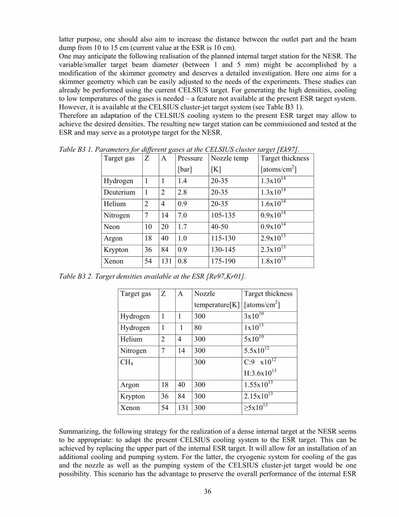
36
latter purpose, one should also aim to increase the distance between the outlet part and the beam dump from 10 to 15 cm (current value at the ESR is 10 cm). One may anticipate the following realisation of the planned internal target station for the NESR. The variable/smaller target beam diameter (between 1 and 5 mm) might be accomplished by a modification of the skimmer geometry and deserves a detailed investigation. Here one aims for a skimmer geometry which can be easily adjusted to the needs of the experiments. These studies can already be performed using the current CELSIUS target. For generating the high densities, cooling to low temperatures of the gases is needed – a feature not available at the present ESR target system. However, it is available at the CELSIUS cluster-jet target system (see Table B3 1). Therefore an adaptation of the CELSIUS cooling system to the present ESR target may allow to achieve the desired densities. The resulting new target station can be commissioned and tested at the ESR and may serve as a prototype target for the NESR. Table B3 1. Parameters for different gases at the CELSIUS cluster target [Ek97].
Target gas Z A Pressure [bar]
Nozzle temp [K]
Target thickness [atoms/cm2]
Hydrogen 1 1 1.4 20-35 1.3x10¹⁴ Deuterium 1 2 2.8 20-35 1.3x10¹⁴ Helium 2 4 0.9 20-35 1.6x10¹⁴ Nitrogen 7 14 7.0 105-135 0.9x10¹⁴ Neon 10 20 1.7 40-50 0.9x10¹⁴ Argon 18 40 1.0 115-130 2.9x10¹³ Krypton 36 84 0.9 130-145 2.3x10¹³ Xenon 54 131 0.8 175-190 1.8x10¹³
Table B3 2. Target densities available at the ESR [Re97,Kr01].
Target gas Z A Nozzle temperature[K]
Target thickness [atoms/cm2]
Hydrogen 1 1 300 3x10¹⁰ Hydrogen 1 1 80 1x10¹³ Helium 2 4 300 5x10¹⁰ Nitrogen 7 14 300 5.5x10¹² CH4 300 C:9 x10¹²
H:3.6x10¹³
Argon 18 40 300 1.55x10¹³ Krypton 36 84 300 2.15x10¹³ Xenon 54 131 300 ≥5x10¹³
Summarizing, the following strategy for the realization of a dense internal target at the NESR seems to be appropriate: to adapt the present CELSIUS cooling system to the ESR target. This can be achieved by replacing the upper part of the internal ESR target. It will allow for an installation of an additional cooling and pumping system. For the latter, the cryogenic system for cooling of the gas and the nozzle as well as the pumping system of the CELSIUS cluster-jet target would be one possibility. This scenario has the advantage to preserve the overall performance of the internal ESR

37
target with respect to the very strict vacuum conditions required by the operation of the ring (overall vacuum base pressure close to 10-11mbar). For space requirements, the option of a polarized hydrogen target has to be considered. This option is of particular relevance for the physics program aiming on the test fundamental symmetries. Alternatively, a liquid micro-jet target might be a further interesting option of the realisation of a dense internal target, an option which deserves a more detailed investigation [Gr03]. Currently, the internal target operating at the ESR provides for the light species helium and hydrogen densities of the order 1012-1013 1/cm2. However, densities up to 1016 1/cm2 could be used at the future NESR. In order to achieve such densities, we propose (i) the use of considerably smaller nozzle diameters (d< 5µm) and (ii) much lower source temperatures (T0<20K, depending however on the particular target species). Smaller orifice diameters appear to be the essential step towards increasing the target density by further cooling the nozzle source well below the liquid hydrogen temperature. At the ESR Laval-type nozzles with diameter ≥100µm are commonly used for the production of gas jet targets. However, such large orifice diameters preclude a high degree of source cooling, as the corresponding density increase would lead to a source chamber pressure psource ≈ 1 mbar, or higher. The feasibility to producing continuous droplet beams obtained by expansion through very small orifices (d ≤ 10 µm) has been demonstrated in the last years for both helium and molecular hydrogen. In particular, the properties of 4He droplet beams are now well characterized. Typically, in the above experiments the initial state in the source is well within the gaseous region of the phase diagram. Due to the cooling of the expanding helium gas an extensive condensation to droplets occurs. As a result, the beam in the final stages of the expansion consists of a mixture of He atoms and clusters. The clusters have a typical size (i.e. number of molecules) of N ≈ 102-104 (diameter ≈ 1-10 nm), depending on the source temperature T0 = 10 - 40 K and source pressure P0 = 20 - 80 bar. We plan to conduct a feasibility study for such a target scenario based on test installations and experiments at the current internal target of the ESR. Besides the potential increase of target densities with the use of liquid micro jet targets, such a new internal target technology may improve considerably the performance of both x-ray spectroscopy and reaction dynamics experiments. In particular, the well localized beam-target interaction zone (< 1 µm) as compared to ≥ 1 mm for the gas-jet target would allow for an enhanced momentum resolution and a considerable reduction in Doppler broadening especially when considering the use of micro-calorimeter at moderate energies (e.g. 100 MeV/u). This makes such new internal target concepts worthwhile to be investigated in further detail in near future. Here still open questions about the survival probability of liquid droplets under heavy ion bombardment, beam heating and its recooling after interaction with the target, etc. are to be addressed. Milestones 07-2006 performance tests of a modified skimmer geometry at the CELSIUS target 12-2006 adaptation of the CELSIUS cooling system to the ESR target 12-2006 results of a feasibility study for a micro-jet target 07-2007 performance test of the CELSIUS target at the ESR finished 07-2007 installation of a micro-jet target at the ESR 01-2008 performance test of a micro-jet target at the ESR finished 07-2008 design of the new target station available 07-2008 design of the NESR support structure available 07-2008 design of target chambers finished 2009 assembly of NESR target 2009 first test operation of the NESR target

38
a. Simulations The modified ESR target will serve as a prototype target. Using this prototype target, all required tests for the final layout and design of the NESR target will be performed at the current ESR. Also the need for differential pumping system for the NESR due to a possible higher gas load for the ESR/NESR UHV system must be investigated. b. Radiation Hardness does not apply c.+d. Design and Construction The modified ESR target will serve as a prototype target. Using this prototype target, all required tests for the final layout and design of the NESR target will be performed at the current ESR. The result we enter in the design and construction of the new NESR target station. e. Acceptance Tests Vacuum requirements (overall vacuum base pressure close to 10-11mbar). This is guaranteed by the pumping system of the ESR internal target station. For the case of dense targets, the additional use of apertures must be investigated to allow for additional differential pumping along the beam line. f. Calibration does not apply g. Requests for Test Beams It is planned to perform all the required modifications already at the present ESR.

39
B 3 1.3 High-Resolution Photon Spectrometers The study of angular distributions and alignment or polarization effects for photon emission induced by atomic collisions will be addressed by a dedicated photon scattering chamber for the NESR jet target (see Figure B3 3). Here, also precision X-ray spectroscopy experiments on H-, He-, and Li-like high-Z ions will be conducted. This research will take advantage of new advanced detector devices such as µ-strip or calorimeter detectors currently under development. Similar to the X-ray detection chamber at the ESR [St00], the chamber will be equipped with various X-ray view ports allowing for a large angular range with respect to the ion beam axis. It is also planned to use the X-ray detection setup in combination with the reaction microscope and the forward electron spectrometer for investigation of the fundamental process of electron-nucleus bremsstrahlung.
jet target
35 deg 60 deg 90 deg 120 deg
beam axis341 mm
Figure B3 3. Photon detection area at the NESR jet target [St00]. B 3 1.3.1 Crystal Spectrometers for Hard X Rays (30–120 keV) For QED investigations of high-Z one-electron systems the K-shell transitions have to be measured with high accuracy. The FOcusing Compensating Asymmetric Laue (FOCAL) crystal optics [Be04] has been developed for accurate spectroscopy in the energy range of approximately 30–120 keV. A pair of such instruments is presently being assembled at the ESR. The parameters of the crystal spectrometers have been optimized as to match present capabilities of position-sensitive X-ray detectors used in these systems. A schematic layout oft the spectrometer principle is given in Figure B3 4.
Figure B3 4. Sketch of the FOCAL X-ray optics viewing the intersection of gas jet and ion beam.
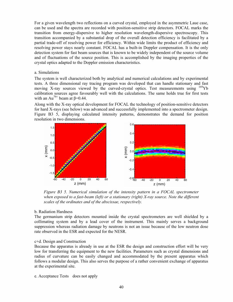
40
For a given wavelength two reflections on a curved crystal, employed in the asymmetric Laue case, can be used and the spectra are recorded with position-sensitive strip detectors. FOCAL marks the transition from energy-dispersive to higher resolution wavelength-dispersive spectroscopy. This transition accompanied by a substantial drop of the overall detection efficiency is facilitated by a partial trade-off of resolving power for efficiency. Within wide limits the product of efficiency and resolving power stays nearly constant. FOCAL has a built-in Doppler compensation. It is the only detection system for fast beam sources that is known to be widely independent of the source volume and of fluctuations of the source position. This is accomplished by the imaging properties of the crystal optics adapted to the Doppler emission characteristics. a. Simulations The system is well characterized both by analytical and numerical calculations and by experimental tests. A three dimensional ray tracing program was developed that can handle stationary and fast moving X-ray sources viewed by the curved-crystal optics. Test measurements using 169Yb calibration sources agree favourably well with the calculations. The same holds true for first tests with an Au79+ beam at β=0.44. Along with the X-ray optical development for FOCAL the technology of position-sensitive detectors for hard X-rays (see below) was advanced and successfully implemented into a spectrometer design. Figure B3 5, displaying calculated intensity patterns, demonstrates the demand for position resolution in two dimensions.
Figure B3 5. Numerical simulation of the intensity pattern in a FOCAL spectrometer when exposed to a fast-beam (left) or a stationary (right) X-ray source. Note the different scales of the ordinates and of the abscissae, respectively.
b. Radiation Hardness The germanium strip detectors mounted inside the crystal spectrometers are well shielded by a collimating system and by a lead cover of the instrument. This mainly serves a background suppression whereas radiation damage by neutrons is not an issue because of the low neutron dose rate observed in the ESR and expected for the NESR. c+d. Design and Construction Because the apparatus is already in use at the ESR the design and construction effort will be very low for transferring the equipment to the new facilities. Parameters such as crystal dimensions and radius of curvature can be easily changed and accommodated by the present apparatus which follows a modular design. This also serves the purpose of a rather convenient exchange of apparatus at the experimental site. e. Acceptance Tests does not apply

41
f+g. Calibration and Request for Test Beams Although the spectrometers have a well established wavelength scale, at least one reference line is needed for accurate wavelength measurements. As transfer standards gamma-ray lines of radioactive isotopes are used. They are mounted in a source positioner that is well shielded by tungsten alloy. For future measurements it is proposed to implement a specially designed calibration-probe facility at the gas-jet target of the storage ring. B 3 1.3.2 Photon Spectrometers for Soft X Rays (3-20 keV) The measurement of n=2 to 2 transitions in very heavy two- and three-electron systems is important for the understanding of relativistic and quantum electrodynamic effects in many-body systems. From previous studies at low nuclear charge it can be concluded that the nonrelativistic part oft the transition energy along with electron–electron correlation effects are well understood but uncertainties remain for the higher-order QED terms becoming pronounced only at very high Z. For the 1s2p3/2,J=2 → 1s2s1/2,J=0 transition the wavelength is near 2.7 Å (4.5 keV), in the region of soft x rays, which is more favourable than the VUV where the spectra of lower Z ions are located, and also more attractive than the hard X-rays of the K-shell transitions. Figure B3 6 displays the transition wavelengths for the two finestructure components J=0 and J=2 as a function of the nuclear charge.
Figure B3 6. Wavelengths for the 1s2p3/2, J=0 and J=2 → 1s2s1/2, J=0 transitions in helium like ions as a function of the nuclear charge Z. Reflection-type crystal optics in combination with position-sensitive X-ray detectors are well suited for accurate spectroscopy of the aforementioned transitions. Such systems have been widely used before for other precision experiments and the technology is readily available. Special care has to be taken to carefully device the optics as to accommodate the peculiarities of a fast moving source with its Doppler characteristics. a. Simulations Characterization of the crystal optics to be used can be performed numerically. The geometries considered comprise Johann, von Hamos or doubly focusing reflection optics. These instruments can be of relatively high luminosity with an overall throughput near 10-6, and still have a spectral resolving power close to 10000. In order to preserve this performance also for a fast moving source as in the present application the optics have to be optimized with respect to the emission characteristics governed by the Doppler effect. This task will be performed by a three-dimensional ray tracing incorporating also the ion beam properties. We plan to use a pair of two spectrometers
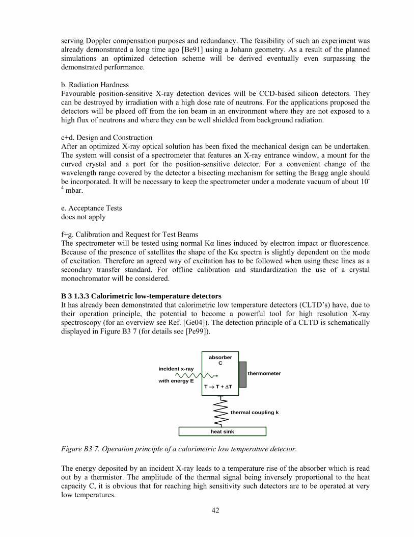
42
serving Doppler compensation purposes and redundancy. The feasibility of such an experiment was already demonstrated a long time ago [Be91] using a Johann geometry. As a result of the planned simulations an optimized detection scheme will be derived eventually even surpassing the demonstrated performance. b. Radiation Hardness Favourable position-sensitive X-ray detection devices will be CCD-based silicon detectors. They can be destroyed by irradiation with a high dose rate of neutrons. For the applications proposed the detectors will be placed off from the ion beam in an environment where they are not exposed to a high flux of neutrons and where they can be well shielded from background radiation. c+d. Design and Construction After an optimized X-ray optical solution has been fixed the mechanical design can be undertaken. The system will consist of a spectrometer that features an X-ray entrance window, a mount for the curved crystal and a port for the position-sensitive detector. For a convenient change of the wavelength range covered by the detector a bisecting mechanism for setting the Bragg angle should be incorporated. It will be necessary to keep the spectrometer under a moderate vacuum of about 10-
4 mbar. e. Acceptance Tests does not apply f+g. Calibration and Request for Test Beams The spectrometer will be tested using normal Kα lines induced by electron impact or fluorescence. Because of the presence of satellites the shape of the Kα spectra is slightly dependent on the mode of excitation. Therefore an agreed way of excitation has to be followed when using these lines as a secondary transfer standard. For offline calibration and standardization the use of a crystal monochromator will be considered. B 3 1.3.3 Calorimetric low-temperature detectors It has already been demonstrated that calorimetric low temperature detectors (CLTD’s) have, due to their operation principle, the potential to become a powerful tool for high resolution X-ray spectroscopy (for an overview see Ref. [Ge04]). The detection principle of a CLTD is schematically displayed in Figure B3 7 (for details see [Pe99]).
incident x-ray with energy E
T → T + ∆T
absorber C
thermometer
heat sink
thermal coupling k
Figure B3 7. Operation principle of a calorimetric low temperature detector. The energy deposited by an incident X-ray leads to a temperature rise of the absorber which is read out by a thermistor. The amplitude of the thermal signal being inversely proportional to the heat capacity C, it is obvious that for reaching high sensitivity such detectors are to be operated at very low temperatures.

43
The potential advantages of calorimetric detectors over conventional ionization detectors are: the smaller energy gap for the creation of an elementary excitation, leading to a better counting statistics of the detected quanta (phonons); the more complete energy detection because both, the energy deposited in phonons and in ionization contribute to the signal; the flexibility in the choice of the absorber material (to be optimized with respect to the detection efficiency); the small noise power at the low operating temperatures. Therefore CLTD’s promise a considerable improvement of the energy resolution in combination with a still reasonable detection efficiency.
cold finger detectorarray
bicycle-wheel
FET-box
Figure B3 8. Setup of the calorimetric low-temperature detector for hard X-rays developed at the University of Mainz [Bl02].
CLTD’s have been recently developed [Bl02] for detection of hard X-rays (E ≤ 100 keV) for application in Lamb shift experiments at the ESR. The detector modules are designed on the basis of silicon microcalorimeters which were developed by the Goddard/Wisconsin groups [St96]. The detector pixels consist of silicon thermistors, which are used as thermometers, and of X-ray absorbers made from Pb and Sn, glued on the top of the thermistors by means of an epoxy varnish. Thermistor arrays consist of 36 pixels each, the active area of 1 pixel being about 1 mm2. To obtain a reasonable detection solid angle the detector arrays have to be located as close as possible to the interaction zone at the internal target of the storage ring.
59.2 59.4 59.6 59.8 60.00
5
10
15
20
25photopeak
coun
ts/b
in
energy [keV]
Figure B3 9. Energy spectrum observed with a calorimetric low-temperature detector with a 0.2 mm² x 47 µm Pb absorber for 59.6 keV photons. For the photo peak an energy resolution of ∆EFWHM = 65 eV is obtained.
To realize this concept a special 3He/4He-dilution refrigerator with a side arm which fits to the internal target geometry was designed (see Figure B3 8). The operating temperature of the detectors

44
may be chosen between 50 mK and 100 mK. The detector performance typically achieved [Bl02] is demonstrated in Figure B3 9, where the energy spectrum obtained for a detector with a 0.2 mm2 x 47 µm Pb absorber for 59.6 keV photons, provided by an 241Am source, is displayed. For the photo peak at 59.6 keV an energy resolution of ∆EFWHM = 65 eV is obtained. This result may be compared to the theoretical limit of the energy resolution for a conventional semiconductor detector which is about ∆E ≈ 380 eV for 60 keV photons. The potential of this detector concept could be demonstrated during a first commissioning beam time perfomed at the internal target of the ESR storage ring. In the experiment bare uranium were decelerated to a beam energy of 90 MeV/u and the characteristic groundstate transitions of H-like uranium were produced in collisions with Ar atoms. A resulting x-ray spectrum is displayed in Figure B3 10.
Figure B3 10: X-ray spectrum (preliminary) of the groundstate transitions in H-like uranium as observed by a micro-calorimeter at the internal target of the ESR storage ring [An05]. The data were accumulated during a 48 hour commissioning run (U91+ → Ar, 90 MeV/u, observation angle: 145o). For the FAIR facility it is also planned to design and build one of a few larger solid angle CLTD’s for high resolution X-ray spectroscopy. It is planned that such detectors will cover the full energy range from a few to 100-200 keV, and will with an active area of 100-200 mm² each combine the advantage of high resolving power with large detection efficiency. The future investigations of the Mainz/GSI group will be made in close collaboration with the Heidelberg group. Within this collaboration it is also planned to consider the detection principle of magnetic calorimeters [Fl04], which bears a large potential, especially for the detection of high energetic X-rays, as an additional option for the investigations within the FAIR project. Additional R&D and an explicit design study are planned for the near future on this topic. For the energy range close to 10 keV, micro-calorimeter systems are know to provide both excellent energy resolution as well as a high detection efficiency. This makes such a detector in particular well suited for experiments such as the proposed 2s-2p laser excitation at SIS300. Recently a feasibility study for micro-calorimeter detectors operating at accelerator beam lines was performed at the ESR storage ring [Si04]. For this test the 1 x 3 micro-calorimeter array and its cryostat were completely enclosed in a copper EMI shield. The solid angle subtended by the detector at the source was 5 × 10⁻⁸ sr. The shield was equipped with a remotely controlled assembly that positioned radioactive sources for calibration. A one hour integration while the ESR and jet target were operating yielded a background rate equal to zero. We accumulated data for a total of 17 hours over

45
a four day period and collected close to 300 photons; a low number but not surprising for an experiment with a solid angle of 5 × 10⁻⁸ sr at the ESR. The spectrum including all of these events is shown in Figure B3 11 (histogram).
Figure B3 11. The microcalorimeter spectrum (histogram) obtained from Au78+. The spectrum measured by a germanium detector reduced by a factor of 2000 is superimposed (smooth solid line). For the energy range close to 10 keV, micro-calorimeter systems are know to provide both excellent energy resolution as well as a high detection efficiency. This makes such a detector in particular well suited for experiments such as the proposed 2s-2p laser excitation at SIS300. Recently a feasibility study for micro-calorimeter detectors operating at accelerator beam lines was performed at the ESR storage ring [Si04]. For this test the 1 x 3 micro-calorimeter array and its cryostat were completely enclosed in a copper EMI shield. The solid angle subtended by the detector at the source was 5 × 10⁻⁸ sr. The shield was equipped with a remotely controlled assembly that positioned radioactive sources for calibration. A one hour integration while the ESR and jet target were operating yielded a background rate equal to zero. We accumulated data for a total of 17 hours over a four day period and collected close to 300 photons; a low number but not surprising for an experiment with a solid angle of 5 × 10⁻⁸ sr at the ESR. The spectrum including all of these events is shown in Figure B3 11 (histogram). For the FAIR facility we plan to build a micro-calorimeter array consisting of 400 pixels; each pixel will be of the type used in the feasibility study discussed above. This detector system will be a replica of the 20 x 20 array that the group at the Harvard-Smithsonian Center for Astrophysics (CfA) is building for a hard X-ray balloon flight to measure the Ti44 emission at 68 keV from supernova explosions [Si01]. The performance of one of these pixels is shown in Figure B3 11Figure B3 12. We also point out that the detector array will not use liquid cryogens or mechanical heat switches that require intervention from technical personnel for their operation. Rather, a mechanical cryocooler will be used to reach 4.2 K and the instrument will use electromechanical heat switches. This will make it possible to operate the micro-calorimeter system remotely and continuously without user intervention.
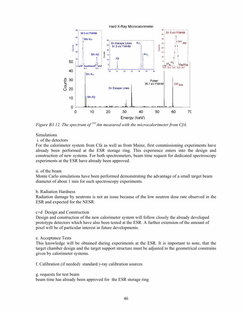
46
Figure B3 12. The spectrum of 241Am measured with the microcalorimeter from CfA.
Simulations i. of the detectors For the calorimeter system from Cfa as well as from Mainz, first commissioning experiments have already been performed at the ESR storage ring. This experience enters into the design and construction of new systems. For both spectrometers, beam time request for dedicated spectroscopy experiments at the ESR have already been approved. ii. of the beam Monte Carlo simulations have been performed demonstrating the advantage of a small target beam diameter of about 1 mm for such spectroscopy experiments. b. Radiation Hardness Radiation damage by neutrons is not an issue because of the low neutron dose rate observed in the ESR and expected for the NESR. c+d Design and Construction Design and construction of the new calorimeter system will follow closely the already developed prototype detectors which have also been tested at the ESR. A further extension of the amount of pixel will be of particular interest in future developments. e. Acceptance Tests This knowledge will be obtained during experiments at the ESR. It is important to note, that the target chamber design and the target support structure must be adjusted to the geometrical constrains given by calorimeter systems. f. Calibration (if needed) standard γ-ray calibration sources g. requests for test beam beam time has already been approved for the ESR storage ring

47
B 3 1.3.4 X-ray Optics for Photon Spectroscopy An important part of the experimental atomic physics program at NESR is the precision X-ray spectroscopy of photons emitted from radiative electron capture (REC) of ions with atoms at the internal gas target or the radiative recombination (RR) of ions with free cold electrons in the electron cooler (e-cool), electron target (e-target) and electron collider (e-collider). Intense beams of stored few-electron or bare ions, up to completely stripped U92+, which will be available at the NESR, colliding with cold atomic and electronic beams, offer new possibilities to access both the structure (e.g. QED and relativistic effects) as well as the dynamics (e.g. recombination in cold magnetized plasma) of electron-ion interaction by using the latest development in the field of X-ray spectroscopy. In particular, by combining the focusing X-ray optics with newly developed detectors, such as the position-sensitive (2D/3D) semiconductor detectors or high resolution (few eV) micro calorimeters, may provide a new access to precision studies. As an example, the polarization of hard X-ray photons can be measured with 2D/3D position sensitive detectors by exploiting the Compton effect. Similarly, combining the X-ray focusing optics with high-resolution, but low-efficiency, crystal diffraction spectroscopy, high-precision X-ray measurements can be performed at the NESR, which are of fundamental interest (QED effects). The X-ray optic uses the X-ray reflection phenomenon, which behaves differently depending on the angle of incidence of X-rays. Namely, for incident angles below the critical angle Ecrit /1∝θ the primary photon beam is totally (≈ 100%) reflected (total external reflection), while for the angles
critθθ > the reflection coefficient is much smaller, decreasing with photon energy. For this reason, usually, for critθθ > the multilayer (or super multilayer) mirrors increasing the reflection coefficient are used, consisting of the repeated (N ~ 100-1000) structure high-Z/low-Z material bilayers (e.g. 600 W/Si super multilayer. Generally, the X-ray optics based on the total reflection phenomenon is simpler and more effective (near 100% reflectivity), moreover, the polycapillary X-ray optics elements are recently available commercially, which can be directly used as the X-ray focusing elements. For the X-ray spectroscopy experiments foreseen at the NESR the following X-ray focusing instruments are planned to be installed:
1) polycapillary X-ray focusing optics (PXFO) at the gas target 2) multilayer X-ray focusing lens (MXFL) at the gas target 3) total reflection cylindrical mirror (TRCM) at the electron cooler/target
Detailed technical aspects of this X-ray instrumentation are addressed below.
Figure B3 13. A schematic representation of the use of an X-ray optics to transfer the X-rays produced in the electron cooler to a micro calorimeter located in the experimental area without constraints on the amount of floor space.
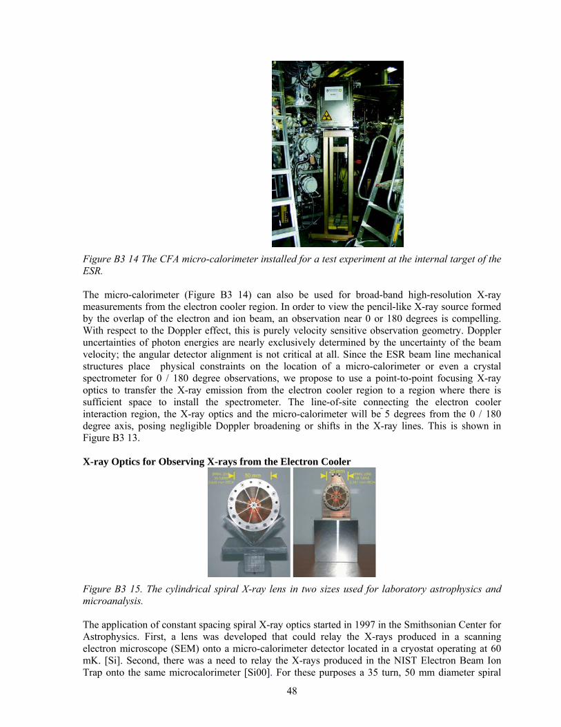
48
Figure B3 14 The CFA micro-calorimeter installed for a test experiment at the internal target of the ESR. The micro-calorimeter (Figure B3 14) can also be used for broad-band high-resolution X-ray measurements from the electron cooler region. In order to view the pencil-like X-ray source formed by the overlap of the electron and ion beam, an observation near 0 or 180 degrees is compelling. With respect to the Doppler effect, this is purely velocity sensitive observation geometry. Doppler uncertainties of photon energies are nearly exclusively determined by the uncertainty of the beam velocity; the angular detector alignment is not critical at all. Since the ESR beam line mechanical structures place physical constraints on the location of a micro-calorimeter or even a crystal spectrometer for 0 / 180 degree observations, we propose to use a point-to-point focusing X-ray optics to transfer the X-ray emission from the electron cooler region to a region where there is sufficient space to install the spectrometer. The line-of-site connecting the electron cooler interaction region, the X-ray optics and the micro-calorimeter will be 5 degrees from the 0 / 180 degree axis, posing negligible Doppler broadening or shifts in the X-ray lines. This is shown in Figure B3 13. X-ray Optics for Observing X-rays from the Electron Cooler
Figure B3 15. The cylindrical spiral X-ray lens in two sizes used for laboratory astrophysics and microanalysis. The application of constant spacing spiral X-ray optics started in 1997 in the Smithsonian Center for Astrophysics. First, a lens was developed that could relay the X-rays produced in a scanning electron microscope (SEM) onto a micro-calorimeter detector located in a cryostat operating at 60 mK. [Si]. Second, there was a need to relay the X-rays produced in the NIST Electron Beam Ion Trap onto the same microcalorimeter [Si00]. For these purposes a 35 turn, 50 mm diameter spiral

49
with a constant spacing of 0.635 mm has been designed and built. These two spiral lenses are shown in Figure B3 15. The plastic is 25 mm wide and is coated with Au.
a. Simulations In Figure B3 16 we compare the X-ray intensity at the detector with and without the spiral lens. For a laboratory experiment where the focal length was one meter, a gain of 300 was obtained at low energies. The focal lengths and hence the energy range are easily changed to fit the application without rebuilding the spiral lens. Imaging results are shown in Figure B3 17.
Figure B3 16. (Left) X-ray continuum spectra obtained with and without the 50 mm diameter spiral optic. The focal length used for this experiment was 1 m (Right). The ratio of the two spectra yields the gain provided by using the optics. The proposed X-ray focusing optics instrumentation (PXFO, MXFL, TRCM) which will be used in the experiments in the NESR needs detailed simulation studies including X-ray source geometry (point-like source for gas-jet/ion-beam and extended liner source for merged electron/ion beams), X-ray focusing optics including specular characteristic, and X-ray detector geometry and efficiency. The goals of these simulations are the following:
1. To find optimum solution with respect of available X-ray technology, installation requirements, costs and instrument performance.
2. To model the response of instruments at experimental conditions (count rates, resolution, simulated spectra).
3. To find the optimized parameters of instruments for technical designs.
Figure B3 17. Imaging results using the small spiral lens shown in Figure B3 15.
b. Radiation Hardness

50
Radiation hardness of X-ray optics for NESR seems not to be a problem due to the fact that this instrumentation is not exposed directly to the ion beam. On the other hand the expected intensities of X-rays at the NESR are small, requiring instead X-ray focusing elements.
c. Design In design stage the results of the simulations will be used as well as the contacts with high-tech companies offering commercially focusing X-ray optics.
d. Construction Construction of polycapillary X-ray focusing optics (PXFO) and total reflection cylindrical mirror (TRCM) will be ordered by specialized company experienced in manufacturing the X-ray optics elements.
e. Acceptance Tests The X-ray optics developed for X-ray experiments at the NESR need special tests of their quality (precision of fabrication, surface smoothness, coatings, alignment, specular characteristics, and focusing ratio). These acceptance tests can be performed using conventional X-ray tube and synchrotron radiation sources
f. Calibration On-beam alignment test and calibration of the X-ray optics instrumentation is required to check in situ the performance (focusing, resolution) of the constructed focusing elements. g. Requests for Test Beams Estimated beam time requests is 2 times 2 days beam time per instrument within half a year.
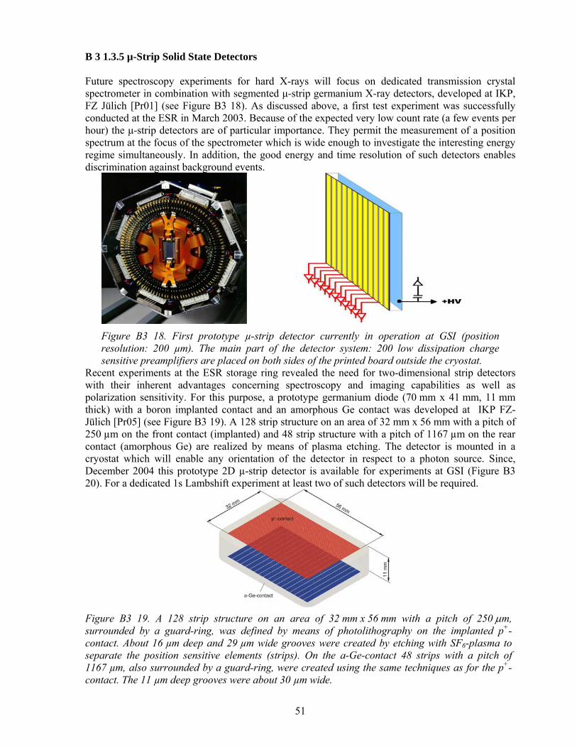
51
B 3 1.3.5 µ-Strip Solid State Detectors Future spectroscopy experiments for hard X-rays will focus on dedicated transmission crystal spectrometer in combination with segmented µ-strip germanium X-ray detectors, developed at IKP, FZ Jülich [Pr01] (see Figure B3 18). As discussed above, a first test experiment was successfully conducted at the ESR in March 2003. Because of the expected very low count rate (a few events per hour) the µ-strip detectors are of particular importance. They permit the measurement of a position spectrum at the focus of the spectrometer which is wide enough to investigate the interesting energy regime simultaneously. In addition, the good energy and time resolution of such detectors enables discrimination against background events.
Figure B3 18. First prototype µ-strip detector currently in operation at GSI (position resolution: 200 µm). The main part of the detector system: 200 low dissipation charge sensitive preamplifiers are placed on both sides of the printed board outside the cryostat.
Recent experiments at the ESR storage ring revealed the need for two-dimensional strip detectors with their inherent advantages concerning spectroscopy and imaging capabilities as well as polarization sensitivity. For this purpose, a prototype germanium diode (70 mm x 41 mm, 11 mm thick) with a boron implanted contact and an amorphous Ge contact was developed at IKP FZ-Jülich [Pr05] (see Figure B3 19). A 128 strip structure on an area of 32 mm x 56 mm with a pitch of 250 µm on the front contact (implanted) and 48 strip structure with a pitch of 1167 µm on the rear contact (amorphous Ge) are realized by means of plasma etching. The detector is mounted in a cryostat which will enable any orientation of the detector in respect to a photon source. Since, December 2004 this prototype 2D µ-strip detector is available for experiments at GSI (Figure B3 20). For a dedicated 1s Lambshift experiment at least two of such detectors will be required.
Figure B3 19. A 128 strip structure on an area of 32 mm x 56 mm with a pitch of 250 µm, surrounded by a guard-ring, was defined by means of photolithography on the implanted p+-contact. About 16 µm deep and 29 µm wide grooves were created by etching with SF6-plasma to separate the position sensitive elements (strips). On the a-Ge-contact 48 strips with a pitch of 1167 µm, also surrounded by a guard-ring, were created using the same techniques as for the p+-contact. The 11 µm deep grooves were about 30 µm wide.
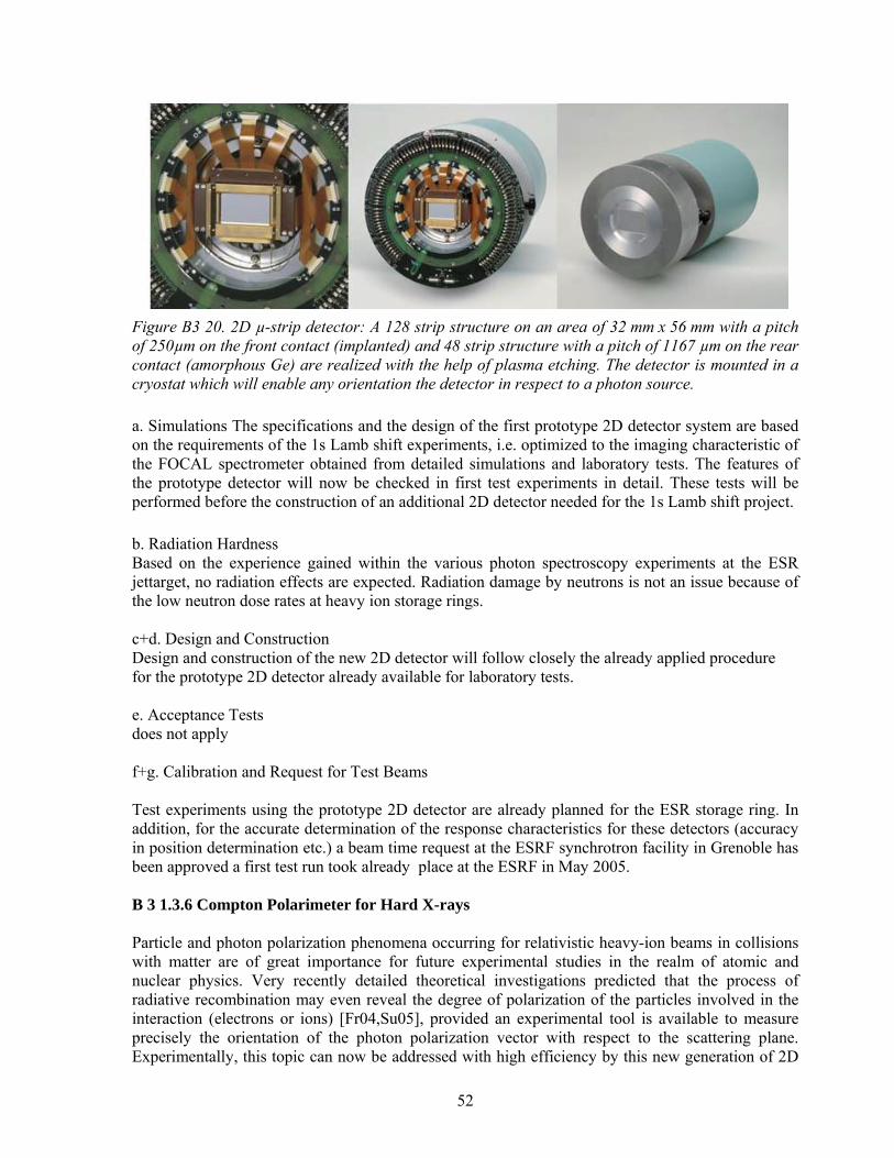
52
Figure B3 20. 2D µ-strip detector: A 128 strip structure on an area of 32 mm x 56 mm with a pitch of 250µm on the front contact (implanted) and 48 strip structure with a pitch of 1167 µm on the rear contact (amorphous Ge) are realized with the help of plasma etching. The detector is mounted in a cryostat which will enable any orientation the detector in respect to a photon source. a. Simulations The specifications and the design of the first prototype 2D detector system are based on the requirements of the 1s Lamb shift experiments, i.e. optimized to the imaging characteristic of the FOCAL spectrometer obtained from detailed simulations and laboratory tests. The features of the prototype detector will now be checked in first test experiments in detail. These tests will be performed before the construction of an additional 2D detector needed for the 1s Lamb shift project. b. Radiation Hardness Based on the experience gained within the various photon spectroscopy experiments at the ESR jettarget, no radiation effects are expected. Radiation damage by neutrons is not an issue because of the low neutron dose rates at heavy ion storage rings. c+d. Design and Construction Design and construction of the new 2D detector will follow closely the already applied procedure for the prototype 2D detector already available for laboratory tests. e. Acceptance Tests does not apply f+g. Calibration and Request for Test Beams Test experiments using the prototype 2D detector are already planned for the ESR storage ring. In addition, for the accurate determination of the response characteristics for these detectors (accuracy in position determination etc.) a beam time request at the ESRF synchrotron facility in Grenoble has been approved a first test run took already place at the ESRF in May 2005. B 3 1.3.6 Compton Polarimeter for Hard X-rays Particle and photon polarization phenomena occurring for relativistic heavy-ion beams in collisions with matter are of great importance for future experimental studies in the realm of atomic and nuclear physics. Very recently detailed theoretical investigations predicted that the process of radiative recombination may even reveal the degree of polarization of the particles involved in the interaction (electrons or ions) [Fr04,Su05], provided an experimental tool is available to measure precisely the orientation of the photon polarization vector with respect to the scattering plane. Experimentally, this topic can now be addressed with high efficiency by this new generation of 2D
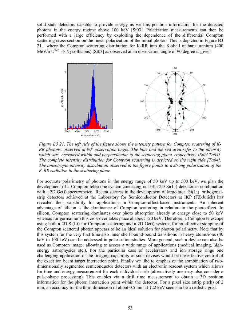
53
solid state detectors capable to provide energy as well as position information for the detected photons in the energy regime above 100 keV [St03]. Polarization measurements can then be performed with a large efficiency by exploiting the dependence of the differential Compton scattering cross-section on the linear polarization of the initial photon. This is depicted in Figure B3 21, where the Compton scattering distribution for K-RR into the K-shell of bare uranium (400 MeV/u U92+ → N2 collisions) [St03] as observed at an observation angle of 90 degree is given.
Figure B3 21. The left side of the figure shows the intensity pattern for Compton scattering of K-RR photons, observed at 900 observation angle. The blue and the red area refer to the intensity which was measured within and perpendicular to the scattering plane, respectively [St04,Ta04]. The complete intensity distribution for Compton scattering is depicted on the right side [Ta04]. The anisotropic intensity distribution observed in the figure points to a strong polarization of the K-RR radiation in the scattering plane.
For accurate polarimetry of photons in the energy range of 50 keV up to 500 keV, we plan the development of a Compton telescope system consisting out of a 2D Si(Li) detector in combination with a 2D Ge(i) spectrometer. Recent success in the development of large-area Si(Li) orthogonal-strip detectors achieved at the Laboratory for Semiconductor Detectors at IKP (FZ-Jülich) has revealed their capability for applications in Compton-effect-based instruments. An inherent advantage of silicon is the dominance of Compton scattering in relation to the photoeffect. In silicon, Compton scattering dominates over photo absorption already at energy close to 50 keV whereas for germanium this crossover takes place at about 120 keV. Therefore, a Compton telescope using both a 2D Si(Li) for Compton scattering and a 2D Ge(i) systems for an effective stopping of the Compton scattered photon appears to be an ideal solution for photon polarimetry. Note that by this system for the very first time also inner shell bound-bound transitions in heavy atoms/ions (40 keV to 100 keV) can be addressed in polarisation studies. More general, such a device can also be used as Compton imager allowing to access a wide range of applications (medical imaging, high-energy astrophysics etc.). For the particular case of accelerators and ion storage rings one challenging application of the imaging capability of such devises would be the effective control of the exact ion beam target interaction point. Finally we like to emphasize the combination of two-dimensionally segmented semiconductor detectors with an electronic readout system which allows for time and energy measurement for each individual strip (alternatively one may also consider a pulse-shape processing). This enables via a drift time measurement to obtain a 3D position information for the photon interaction point within the detector. For a pixel size (strip pitch) of 2 mm, an accuracy for the third dimension of about 0.5 mm at 122 keV seems to be a realistic goal.

54
For the Compton telescope under discussion (see Figure B3 22) we aim for the following specifications: a set of 32x32 orthogonal strips with a pitch of 2 mm for both of the crystals (Si(Li) and Ge(i)). For the crystal thicknesses a value of 2 cm is desired.
Figure B3 22. A Compton telescope system consisting out of a 2D/3D Si(Li) detector in combination with a 2D/3D Ge(i) spectrometer. The telescope has the following specification: 32x32 orthogonal strips with a pitch of 2 mm for both of the crystals (Si(Li) and Ge(i)). a. Simulations Detailed simulations based on experiments and laboratory tests using a 4x4 germanium pixel detector were performed within the PHD thesis of S. Tashenov [Ta05]. The results were cross- checked on the basis of the EGS4 code. b. Radiation Hardness Radiation damage by neutrons is not an issue because of the low neutron dose rate observed in the ESR and expected for the NESR. c+d. Design and Construction Design and construction of the new 2D detector will follow closely the already applied procedure for the prototype 2D detector already available for laboratory tests. In particular, we will take advantage of the great experience in the design and construction of Compton polarimeter already collected at the Laboratory for Semiconductor Detectors at IKP (FZ-Jülich) [Pr05]. e. Acceptance Tests does not apply f+g. Calibration and Request for Test Beams
Figure B3 23: 2D image for Compton scattering of almost 100% linearly polarized x-rays (210 keV) (preliminary result). The image was reorded during a detector performance test at the ESRF synchrotron facility [Sp06]. Test experiments using the prototype 2D detector are already planned for the ESR storage ring. In addition, for the accurate determination of the response characteristics for these detectors (accuracy in position determination, polarization sensitivity etc.) beam times will be requested at the ESRF synchrotron facility in Grenoble (see also section 1.3.5). A first run already took place at the ESRF

55
synchrotron in May 2005 were the response of the first 2D prototype detector on 98% linearly polarized x-ray has been measured for energies in the range between 60 and 340 keV (compare Figure B3 23). B 3 1.4 Electron Spectroscopy at the Internal Target With the new facilities, nuclear excitations in a broad range and in selective ways can be performed with stored bare ions or with ions carrying only one or few electrons. The precise measurement of conversion electron energies allows determination of electronic ground state binding energies at a level of ~ 3 ppm resulting in QED tests at a level of ~2 x 10⁻³ for the 1s self energy in heavy ions. In this case the natural-line-width problem of excited atomic states is absent. Furthermore, from conversion coefficients, the electronic wave function at the site of the nucleus can be probed in the high Z regime as well as the influence of neighbour electrons via selected ionic charges. New insight into nuclear de-excitation schemes for radioactive and excited nuclei is expected from conversion electron spectroscopy [Ma88,Be99,Li03]. With the controlled way of selected ionic species together with particular nuclear states, the conversion decay can be studied at sensitive boundaries. These boundaries are adjusted by HFS-levels, selected electronic multiplet configurations (core + Rydberg state, core excited levels, externally applied magnetic or electric fields…). It will reveal details of the involved nuclear transition matrix elements, transition multipolarities, and spin-parity relations. The future facility offers a large variety of combinations of nuclear and ionic states. A zero degree electron spectrometer will be employed at the NESR internal target which takes advantage of the swift ion emitter’s solid angle transformation into the laboratory frame. This will enable high resolution studies of electrons resulting from atomic or nuclear processes in the range up to 1 MeV. Low cross section events with small emitted electron energy can be favorably measured with high sensitivity and resolution. Figure B3 24 displays the concept of our electron spectrometer system. The first of two main components [Ma88] is a dispersion-free 270o dipole magnet with a large momentum acceptance of δp/p ~ 2.5. Electrons within a solid angle of ~ 1% are transported through a forward acceptance angle of ±2o with respect to the projectile direction onto an intermediate focus outside and perpendicular to the beam line. A large acceptance results from a close distance of 150 mm to the interacting zone (internal gas jet) and a gap spacing of the dipole as required by the necessary vertical beam extension of greater than 80 mm. In horizontal direction, the dispersion plane, a beam extension of 250 mm is covered. Figure B3 25 shows the acceptance efficiency in dependence of the electron energy Ecm in the emitter’s frame. A solid state detector (Si-detector) allows fast measurements at low energy resolution as defined stringently by the kinematical broadening from the large angular acceptance. This resolution is adjustable by collimators at the expense of solid angle acceptance. For measurements with high resolution a second spectrometer replaces the solid state detector. A magnetic analyzer of large dispersion (r-1/2 – field, radius ~ 1 m, momentum resolution δp/p < 10-4, reproducibility ~ 10-5) with angle-limiting collimator slits will be used. For 100 keV electrons a field strength of ~ 10 G has to be controlled at a level of <10-5 which demands preferably construction of an iron free spectrometer. A reproducibility of 2x10⁻⁵ was already achieved by the non-iron free BILL-spectrometer [Ma78] as displayed in Figure B3 24. A two dimensional position sensitive 2D – detector with a resolution of 0.1 mm serves as spectrum imager improving the sensitivity of the instrument. The absolute energy calibration of the spectrometer is provided by an electron gun (< 50 keV) which itself is calibrated by known Auger transitions excited in Ne, Ar, Xe atoms within 0.1 eV accuracy. For higher energies γ-sources will be used.
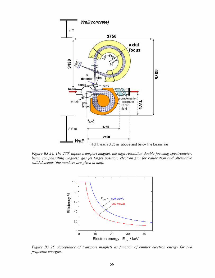
56
Figure B3 24. The 270o dipole transport magnet, the high resolution double focusing spectrometer, beam compensating magnets, gas jet target position, electron gun for calibration and alternative solid detector (the numbers are given in mm).
0 10 20 30 400
20
40
60
80
100
Effi
cien
cy %
Electron energy Ecm / keV
E proj. = 500 MeV/u
200 MeV/u
Figure B3 25. Acceptance of transport magnets as function of emitter electron energy for two projectile energies.
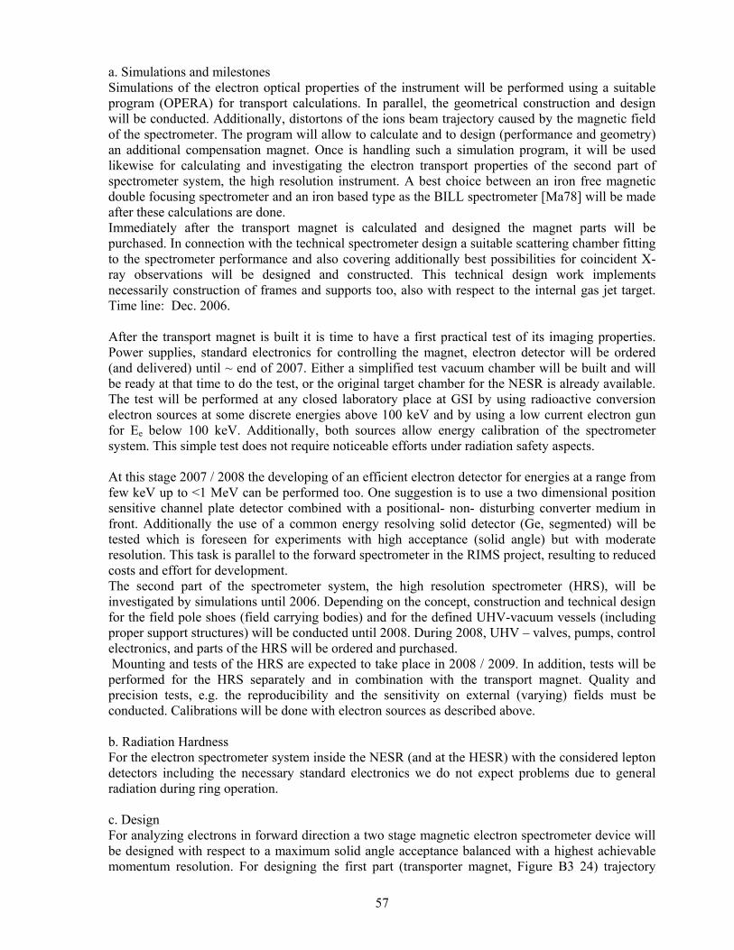
57
a. Simulations and milestones Simulations of the electron optical properties of the instrument will be performed using a suitable program (OPERA) for transport calculations. In parallel, the geometrical construction and design will be conducted. Additionally, distortons of the ions beam trajectory caused by the magnetic field of the spectrometer. The program will allow to calculate and to design (performance and geometry) an additional compensation magnet. Once is handling such a simulation program, it will be used likewise for calculating and investigating the electron transport properties of the second part of spectrometer system, the high resolution instrument. A best choice between an iron free magnetic double focusing spectrometer and an iron based type as the BILL spectrometer [Ma78] will be made after these calculations are done. Immediately after the transport magnet is calculated and designed the magnet parts will be purchased. In connection with the technical spectrometer design a suitable scattering chamber fitting to the spectrometer performance and also covering additionally best possibilities for coincident X-ray observations will be designed and constructed. This technical design work implements necessarily construction of frames and supports too, also with respect to the internal gas jet target. Time line: Dec. 2006. After the transport magnet is built it is time to have a first practical test of its imaging properties. Power supplies, standard electronics for controlling the magnet, electron detector will be ordered (and delivered) until ~ end of 2007. Either a simplified test vacuum chamber will be built and will be ready at that time to do the test, or the original target chamber for the NESR is already available. The test will be performed at any closed laboratory place at GSI by using radioactive conversion electron sources at some discrete energies above 100 keV and by using a low current electron gun for Ee below 100 keV. Additionally, both sources allow energy calibration of the spectrometer system. This simple test does not require noticeable efforts under radiation safety aspects. At this stage 2007 / 2008 the developing of an efficient electron detector for energies at a range from few keV up to <1 MeV can be performed too. One suggestion is to use a two dimensional position sensitive channel plate detector combined with a positional- non- disturbing converter medium in front. Additionally the use of a common energy resolving solid detector (Ge, segmented) will be tested which is foreseen for experiments with high acceptance (solid angle) but with moderate resolution. This task is parallel to the forward spectrometer in the RIMS project, resulting to reduced costs and effort for development. The second part of the spectrometer system, the high resolution spectrometer (HRS), will be investigated by simulations until 2006. Depending on the concept, construction and technical design for the field pole shoes (field carrying bodies) and for the defined UHV-vacuum vessels (including proper support structures) will be conducted until 2008. During 2008, UHV – valves, pumps, control electronics, and parts of the HRS will be ordered and purchased. Mounting and tests of the HRS are expected to take place in 2008 / 2009. In addition, tests will be performed for the HRS separately and in combination with the transport magnet. Quality and precision tests, e.g. the reproducibility and the sensitivity on external (varying) fields must be conducted. Calibrations will be done with electron sources as described above. b. Radiation Hardness For the electron spectrometer system inside the NESR (and at the HESR) with the considered lepton detectors including the necessary standard electronics we do not expect problems due to general radiation during ring operation. c. Design For analyzing electrons in forward direction a two stage magnetic electron spectrometer device will be designed with respect to a maximum solid angle acceptance balanced with a highest achievable momentum resolution. For designing the first part (transporter magnet, Figure B3 24) trajectory

58
calculations will be performed. This also defines the design of the best geometry of target chamber which also has to fulfill the conditions for the gas jet target, beam volume operation and flanges for additional detectors (X-ray, recoil ions) and for an electron gun for calibration. Likewise compensation magnets to correct beam trajectory disturbance will be designed. The design of the high resolution spectrometer (HRS) follows after simulations of trajectory calculations have been performed. d. Construction With the results from design studies the defined construction of the components of spectrometer system will be performed by experts of the collaboration (see chapter G). e. Acceptance Tests Manufactored parts (chamber, transporter- and correcting magnets, HRS, calibration electron gun etc.) will be tested step by step at a laboratory place at GSI and carried by the collaboration. Besides the functionality of components the UHV compatibility will be proofed by the UHV group. f. Calibration at first calibrations of instrumental components will be conducted during the acceptance test. This probes instrumental sensitivity, resolution, reproducibility, position sensitive detector. β-calibration sources and electron gun will be used. During operation with ion projectiles, known electron emission energies and cross sections from .atomic excitation, capture and ionization reactions are available. In particular, kinematical line shifts and line doubling from discrete projectile emitter lines and “cusp”-electrons are good calibrators. g. Requests for Test Beams After the spectrometer components have been tested with calibration electron sources test beams of 2 x 4 days at the ESR is requested in order to proceed the commissioning phase. This will detect possible unexpected effects in operation with storage ring beams.

59
B 3 1.5 Extended Reaction Microscope We propose to build an extended reaction microscope for operation in the NESR of the future FAIR complex. The instrument consists of a large solid angle recoil and electron momentum spectrometer for recoiling target ions and slow electrons (described in B 3.1.5.1) combined with an imaging forward electron spectrometer for fast projectile-emitted electrons (described in B 3.1.5.2). Main goals for experiments at this time encompass kinematically complete investigations of a) atomic fragmentation/ multiple ionization and the associated many-electron continua in collisions induced by very highly charged ions which are characterized by very rapidly varying electromagnetic fields with E-field amplitudes up to 2x10¹⁶ V/cm. b) the nature of the ionization process in the non-perturbative regime in ion atom collisions close to threshold for very large Sommerfeld parameters q/v. c) (e,2e) electron impact ionization of ions. d) the short wavelength limit of the fundamental process of electron nucleus Bremsstrahlung. Experiments under a) can be investigated by the core reaction microscope alone, while those under b) and c) can only be investigated by the combination of the core reaction microscope with the imaging forward electron spectrometer; experiments under d) will use the imaging forward electron spectrometer in combination with segmented Ge(i) detectors.
B 3 1.5.1 Large Solid Angle Spectrometer for Recoil Ions and Low Energy Electrons An Extended Reaction Microscope design has been chosen for the experiments on fundamental processes of ionization and Bremsstrahlung as these instruments combine in a unique fashion a very large solid angle with vector momentum identification of all reaction products. Thus, they are best suited for kinematically complete measurements of single and multiple ionization and excitation processes in the categories of ion-atom and electron-ion collisions. Such measurements necessarily cover a very large range of momentum transfers and require magnetic spectrometers for both electrons (from meV to MeV energies) and for the recoil ions. The spectrometer is designed to serve experiments in the NESR and the LSR, as experiments in the respective rings do not demand major changes of detector configurations. For the experimental location at the LSR a supersonic jet gas target is required of a similar performance as the one to be installed at the NESR. In the LSR due to a greater proximity of the last skimmer of the jet to the target zone the required target density can be achieved with significantly more moderate means than in the NESR. In the standard strictly linear longitudinal configuration of the reaction microscope [Ul03], [Ul97] (see Table B 3.3) a small longitudinal magnetic B-field and a longitudinal electric extraction E-field are generated around the target zone by a pair of Helmholtz coils and resistive potential plates, respectively. Low-energy electrons with an energy from few meV up to 1000 eV and recoil ions with initial energies of typically meV are extracted from the target zone with small extraction voltages of approximately 30V and then guided along the magnetic field lines onto 2D position-sensitive detectors positioned a few degrees from the primary beam direction. In experiments at relativistic velocities the pertinent projectile inner shell ionization cross sections are typically a few barn. However, associated target ionization cross sections (e.g. He) are typically of the order 10-15 cm2 [Ko02].The almost unsurpassed collection efficiency of a reaction microscope entails a severe complication: the total ionization cross section is almost universally dominated by processes with minimum momentum transfer q. So electrons with high multiplicity and very low energy in their respective emitter frame (i.e. laboratory frame for ionized target atoms and projectile frame for

60
ionized projectiles, respectively) and low-energy recoil ions constitute the overwhelming share of charged particles produced in these collisions. This needs to be taken into consideration when designing spectrometers with near 4π solid angle, as proposed here for the reaction microscope.
a. Simulations Experiments under consideration cover the coincident detection of scattered projectiles, electrons with energies between meV and approx. 1 MeV and recoiling target ions with energies in the range of meV. i. of the detectors Large area 2D electron detectors with high position resolution have to be developed which match the electro-optical properties of the spectrometers, particularly taking into consideration the one-to-one mapping of electron and recoil vector momenta. It is planned to focus on the triple layer Hex-Anode design due to their spatial resolving power of fractions of a mm and an increased efficiency in multihit resolution. ii. of the beam , electrons and recoil ion trajectories It is the goal to derive initial momenta and momentum correlations between particles participating in the collision, so a straightforward kinematic relation of their detection location on 2D position sensitive detectors plus time of flight TOF of all particles is essential. All electrons with energies ≤ 1keV and recoiling target ions are guided by common E- and B- fields onto their respective detectors. For this purpose we have begun numerical simulation studies using the OPERA code for trajectories of electrons and ions in different sets of two large aperture toroidal magnetic guiding systems for low-energy electrons and recoil ions, respectively. These calculations for a variety of coil configurations will result in an optimal geometric B-field design. The physics needs determine the targeted precision: the azimuthal angular resolution for electrons in the low energy-electron branch (scattering plane) of the reaction microscope is determined by the time resolution and magnitude of the longitudinal B-field, this puts constraints on useful geometric target dimensions; the simultaneous determination of the relative azimuthal angle of fast and slow electrons in (e,2e) experiment for example determines the scattering plane. b. Radiation Hardness Additional adverse conditions in storage ring environments with beam energies up to few 100 MeV/u such as secondary ions produced with very large range of kinetic energies etc. contribute to a significant level of background seen by all those detectors, which are situated physically close to the orbiting beam (i.e. few cm to the orbiting beam). It is therefore important to remove the large area 2D position sensitive detectors for low-energy electrons and recoiling target ions from the direct view of the target zone or at least from the proximity of the coasting beams. The experience at the ESR advises to particularly address the problem of RF noise interfering with channelplate detector signals (for location see Figure B3 26) and the associated fast electronics. Careful shielding of all signal paths from their origin at detectors in the vicinity of the target zone is mandatory; the complete shielding of channelplate based detectors is complex when a significant loss in detection efficiency is to be avoided. We found that for experiments in environments where also short-pulse lasers are involved several nested shieldings of detectors are necessary. c. Design In spectrometers with near 4π efficiency the largest reaction cross section involved determines the rate at which particles are registered in any detector. Thus, electrons due to target ionization may overload the low energy electron detectors and mask any electron from lower cross section processes. It so appears that the large dynamic range of cross sections involved in these studies makes it necessary, particularly for projectile ionization experiments, to part with the conventional

61
concept of a purely linear TOF design for low energy electrons and recoil ions in the reaction microscope. Based on the results of the electron- and ion optical calculations a final decision about the geometry will be made. As the conventional concept works exceedingly well in single pass operation and for single ionization (SI) of systems with low binding energies [Ul03] as the cross sections under study are of a magnitude comparable to He ionization a flexible solutions for field configurations is under study.
electronspectrometer
gas jet ESRbeam
fluorescencedetection
X-ray chamber orreaction microscopewith Helmholtz coils
Figure B3 26. The present ESR target area is build up on modular components: the gas-jet system is adapted to a versatile exchangeable chamber. In the current configuration, a recoil ion and electron momentum spectrometer at the middle part allows a kinematical analysis of low-energy recoil ions and low energy electrons in combination with a forward electron spectrometer for electrons emitted in a narrow cone around the projectile direction. All components are separately placed and removable outside of the target area. This allows for an easy access of different detector systems (e.g. photon spectrometer) to the collision centre. For the NESR, an even higher flexibility will be obtained for components with considerably larger apertures. We will -among other options- investigate configurations which are slight modifications of the successful standard configuration where the extraction E-field/ guiding B-field are parallel but configured at an angle of typically 100 with respect to the projectile axis. On the other hand, in order to assure optimal background free performance and unambiguous attribution of electrons and recoil ions detected with the respective process under investigation magnetically dispersive toroidal configurations will be studied thus preserving largely the longitudinal extraction configuration originally chosen by Ullrich and co-workers [Ul97]. For this purpose we have begun numerical simulation studies using the OPERA code for trajectories of electrons and ions in a set of two large aperture toroidal magnetic guiding systems for low-energy electrons and recoil ions (see Figure B3 27), respectively. These will be used for studies of relativistic and QED effects in kinematically complete electron impact ionization of H-like U91+ [Ke99], [Na99]. d. Construction First calculations for electron trajectories in a magnetic toroidal sector analyzer for 300 deflection using the OPERA code showed that a unique mapping of primordial electron vector momenta is possible from 2D position and time of flight information in the image plane of the spectrometer. Whereas electron trajectories in a conventional linear solenoidal configuration with exclusive use of Helmholtz coils are characterized by a simple relation between transverse momentum of electrons ( with respect to the optical axis) and time of flight, in the extended toroidal configuration under

62
consideration here this relation is slightly more complex as now also the electron's azimuth determines its time of flight. An instructive example is given in Figure B3 28. It is planned to build a small pilot instrument after completion of the ion/electro-optical design phase to be implemented and extensively tested at the UNILAC. Technical aspects as the question of materials to be used in a UHV environment with typical pressures of 1 10-11 mbar will benefit greatly from the current instrument scheduled to be implemented in the ESR in spring 2006.
Electric extraction field typ. 5 V/cm Magnetic guiding field typ. ≤ 50G recoil detector size 80 mm Ø recoil detector solid angle dΩ ∼ 4π momentum resolution ∆p/p ∼ few10-2 low energy electrons energy meV to1000eV
dΩ ∼ 4π ∆p/p ∼ 10-2
cross section beam/jet ≤3 x 3 mm
Table B 3 3. Some tentative Properties of the Recoil and Electron Momentum Spectrometer Section of the Extended Reaction Microscope.
Figure B3 27: Combined recoil and low energy electron spectrometer as part of the Extended Reaction Microscope in the NESR. The forward imaging electron spectrometer will be following directly downstream to the left. The large difference in momenta of the slow (very much below 1 keV) and the fast electron helps to minimize possible effects of the toroidal coils on the fast electrons moving with near projectile velocity.
Figure B3 28: Comparison of the electron location in the image plane for toroidal( left) and linear(right) magnetic field configurations in the reaction microscope. Note the translation of the image to negative z values for the toroidal configuration. e. Acceptance Tests Individual parts foreseen to be manufactured by external enterprises will undergo extensive testing by the UVH group as is current practice for every instrument to be implemented in the ESR.

63
f. Calibration Calibration of the instrument is most reliably performed via standard well known atomic ionization and capture reaction. The addition of a fast pulsed electron gun greatly facilitates this procedure. g. Requests for Test Beams Extensive test experiments using various beams from the UNILAC will be executed with the pilot instrument to map all essential parameters. B 3 1.5.2 Imaging Fast Forward Electron Spectrometer For kinematically complete spectroscopic studies of electrons ionized out of the projectile and for kinematically complete studies of the electron – nucleus Bremsstrahlung process [Ja03,Ha04] in inverse kinematics (where an electron appears captured into the projectile continuum in coincidence with a Bremsstrahlung photon) an imaging forward electron spectrometer is required to map vector momenta of electrons with velocities close to the projectile velocity i.e. with energies up to approximately one MeV. In projectile ionization the electron ionized out of the projectile carries little momentum with respect to the projectile nucleus as processes with minimum momentum transfer dominate ionization processes. Thus, these electrons appear in the laboratory with nearly the projectile velocity and with emission angles close to 00 with respect to the beam axis. For high resolution spectroscopy of such electrons an imaging magnetic spectrometer matching the reaction microscope will be designed for forward electrons emitted with 00 ± 60 around the projectile beam axis and ve ~ vProjectile to ve ~ 2vProjectile. The requirements for this forward electron spectrometer are determined by its purpose of operation: reconstruction of the primary vector momenta of electrons ionized out of the projectile after momentum analysis. The information on the scattering plane is contained in the respective azimuthal angles of the fast electron in the imaging forward electron spectrometer and either the slow electron mapped in the core reaction microscope, or the x ray photon, respectively, detected in a 3D position sensitive pixel detector in the case of the fundamental process of electron nucleus Bremsstrahlung. The anisotropy in the azimuthal distribution appears imaged onto 2D position sensitive electron detectors. a. Simulations In the following we only discuss the configuration of the electron spectrometer and will not address the X-ray detectors needed additionally for the fundamental process of the electron nucleus Bremsstrahlung; the 3D position sensitive pixel detectors are extensively discussed in the section of photon detectors and their sensitivity for determining the polarization of the detected photon is an additional powerful tool in the study of the dynamics of Bremsstrahlung. Only the electron spectrometer and its detector is discussed here. i. of the detectors for electrons The range of electron energies to be covered by the forward spectrometer is ~ 50keV to ~ 1MeV corresponding to maximum specific energies of ~ 800 MeV/u. The lower part of this range is well covered by channelplate-based 2D-position sensitive detectors with spatial resolution of fractions of a mm and a multihit capability; these detectors are based on the hexagonal anode design of Roentdek. We plan to extend the usefulness of these current, extremely powerful 2D position sensitive multihit-capable electron detectors from presently 50 keV to 1 MeV electron kinetic energy; we will test converters with appropriate negative electron affinity for which highly efficient generation of low energy electrons from incident high energy electrons has been reported. Initial tests simply using an appropriately biased plate in front of a Chevron configuration and a 207Bi source providing electron energies of ~500 keV and ~1 MeV show very encouraging results. At the same time other designs for position sensitive detectors covering the upper energy range, like diamond detectors and Si-Pin diode detectors, will be studied for multihit capabilities.
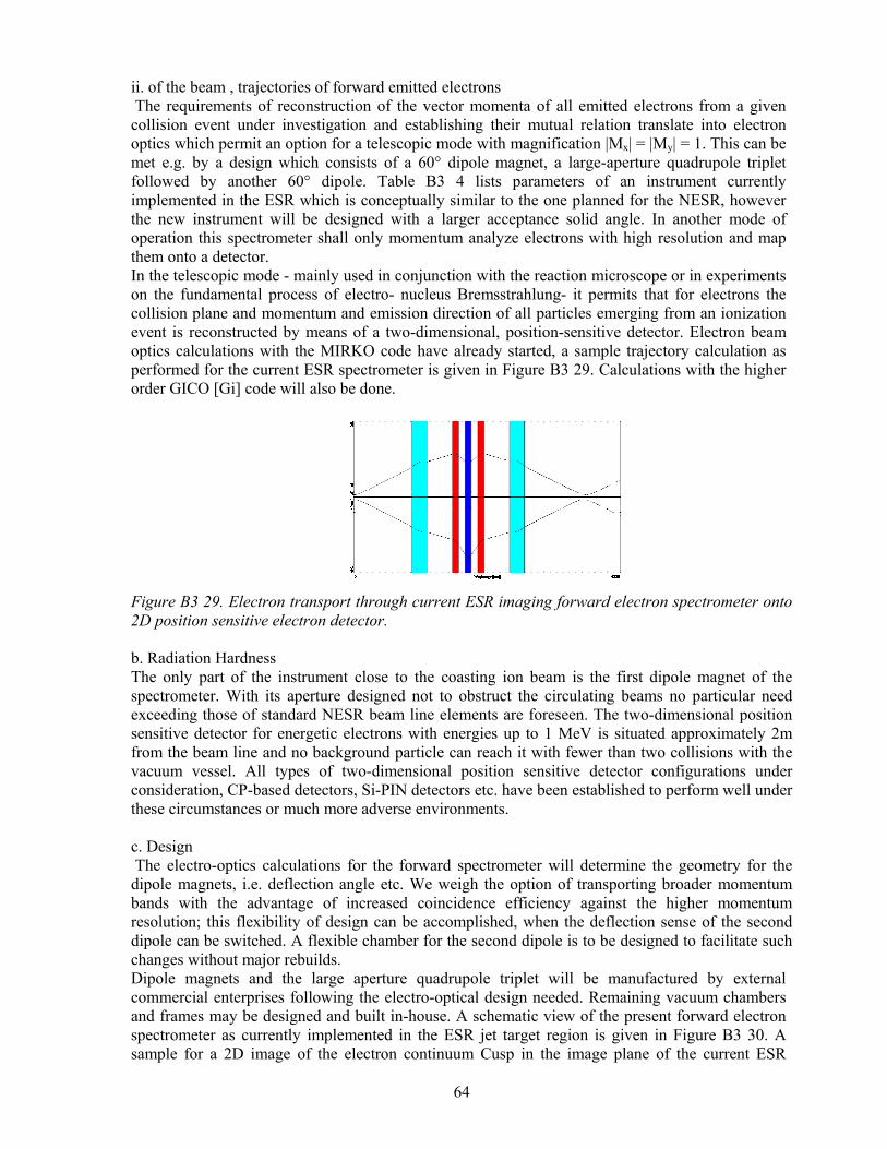
64
ii. of the beam , trajectories of forward emitted electrons The requirements of reconstruction of the vector momenta of all emitted electrons from a given collision event under investigation and establishing their mutual relation translate into electron optics which permit an option for a telescopic mode with magnification |Mx| = |My| = 1. This can be met e.g. by a design which consists of a 60° dipole magnet, a large-aperture quadrupole triplet followed by another 60° dipole. Table B3 4 lists parameters of an instrument currently implemented in the ESR which is conceptually similar to the one planned for the NESR, however the new instrument will be designed with a larger acceptance solid angle. In another mode of operation this spectrometer shall only momentum analyze electrons with high resolution and map them onto a detector. In the telescopic mode - mainly used in conjunction with the reaction microscope or in experiments on the fundamental process of electro- nucleus Bremsstrahlung- it permits that for electrons the collision plane and momentum and emission direction of all particles emerging from an ionization event is reconstructed by means of a two-dimensional, position-sensitive detector. Electron beam optics calculations with the MIRKO code have already started, a sample trajectory calculation as performed for the current ESR spectrometer is given in Figure B3 29. Calculations with the higher order GICO [Gi] code will also be done.
Figure B3 29. Electron transport through current ESR imaging forward electron spectrometer onto 2D position sensitive electron detector. b. Radiation Hardness The only part of the instrument close to the coasting ion beam is the first dipole magnet of the spectrometer. With its aperture designed not to obstruct the circulating beams no particular need exceeding those of standard NESR beam line elements are foreseen. The two-dimensional position sensitive detector for energetic electrons with energies up to 1 MeV is situated approximately 2m from the beam line and no background particle can reach it with fewer than two collisions with the vacuum vessel. All types of two-dimensional position sensitive detector configurations under consideration, CP-based detectors, Si-PIN detectors etc. have been established to perform well under these circumstances or much more adverse environments. c. Design The electro-optics calculations for the forward spectrometer will determine the geometry for the dipole magnets, i.e. deflection angle etc. We weigh the option of transporting broader momentum bands with the advantage of increased coincidence efficiency against the higher momentum resolution; this flexibility of design can be accomplished, when the deflection sense of the second dipole can be switched. A flexible chamber for the second dipole is to be designed to facilitate such changes without major rebuilds. Dipole magnets and the large aperture quadrupole triplet will be manufactured by external commercial enterprises following the electro-optical design needed. Remaining vacuum chambers and frames may be designed and built in-house. A schematic view of the present forward electron spectrometer as currently implemented in the ESR jet target region is given in Figure B3 30. A sample for a 2D image of the electron continuum Cusp in the image plane of the current ESR

65
imaging forward electron spectrometer is given in Figure B3 31. The new instrument for the NESR is intended to allow the covering of a much larger phase space of the projectile continuum than previously possible with the prototype currently implemented in the ESR.
Figure B3 30. Top view on the jet target area with the current ESR 00 imaging electron spectrometer. The space requirements of one arm of the FOCAL high resolution X-ray crystal spectrometer are indicated by the footprint. The new instrument will conceptually have optical properties closely related to the above imaged one.
d. Construction The electro-optical elements will be designed and then manufactured by outside commercial vendors following standard procedures of the GSI magnet group. Hardware like magnet stands and frames, collimating slits, vacuum chambers and all associated fittings can be purchased commercially or be built in house.
600 Dipol-Quad.Triplet-600 Dipole detector : 2D position sensitive multi-hit capable
electron detector (80mmØ) aperture: 250mm(horiz.) x 100mm(vert.) Radius of curvature: reff = 229mm ( measured)
rcalc = 226mm electron energy range 10 keV – 600keV acceptance angle 00 ± 30 minimum momentum resolution p/∆p up to ~1600 telescopic mode |Mx| = |My|=1
Table B3 4. Parameters of present ESR 00 Imaging Electron Spectrometer associated with recoil-and electron momentum spectrometer. e. Acceptance Tests The magnet group will perform all standard tests and field mappings on the site of the manufacturer and subsequently at GSI to establish that the modules of the instrument conform to the specifications.

66
Figure B3 31 Electrons from the continuum Cusp in the image plane of the current ESR prototype imaging forward electron spectrometer for 90 MeV/u U88+ + N2 ; the horizontal slit aperture is 50mm. f.+g. Calibration and Requests for Test Beams The instrument will after completion of acceptance tests be energy-calibrated using beta-sources. The electro-optical performance will be tested as well during this procedure. Before implementation into the storage ring the spectrometer will undergo extensive tests on the background suppression with beams at the low energy Cave A

67
B 3 1.6 Laser Experiments at the NESR The NESR will be one of the work-horses for atomic physics experiments with highly-charge stable and radioactive ions. The situation at the cooler-storage ring especially favors the direct application of laser techniques to the accelerated heavy-ion beams. This has been exploited at the ESR for precision experiments on highly-charged ions, for laser cooling, and for the study of photon-assisted charge changing transitions in the cooler. The properties of the NESR, and its function within the FAIR accelerator facility will offer unique possibilities for several laser experiments. The scope of possible experiments will be dramatically expanded due to the capability to produce intense radioactive beams, the higher beam velocity as compared to the ESR, and additional features like e.g. the electron collider installation. Together with the further improved detection possibilities for particles and photons around the ring this will enable completely new experiments, exploring the electromagnetic interaction in extreme fields and the interplay of electronic and nuclear excitations as well as ground state properties of radioactive ions. Experiments will therefore reach into four different regimes of laser interactions:
1. Visible laser interaction at medium intensities for precision spectroscopy, targeting tests of Special Relativity and QED.
2. Visible laser interaction at ultra-high intensities for the study of electronic and nuclear-
electronic phenomena at high bound-electron energies. 3. X-ray laser spectroscopy of lithium-like radioactive ions for the determination of nuclear
properties. 4. Production of hard X-rays by Thomson backscattering in the electron collider.
The SPARC proposal denotes the following laser proposals for this location:
1. Laser spectroscopy and laser optical pumping of the ground-state hyperfine structure. 2. X-ray laser spectroscopy of Li-like ions. 3. Precision laser spectroscopy as a test of Special Relativity. 4. Interaction of ultra-high intensity laser pulses with heavy ions. 5. Use of Thomson backscattering from the electron collider for the production of energetic
photons. B 3 1.6.1 Laser Spectroscopy and Laser Optical Pumping of the Ground-State Hyperfine Structure Laser spectroscopy of the ground state hyperfine structure of highly charged ions was performed on selected cases at the ESR. It has the potential to provide high precision data on the QED effects in highly charged systems with an accuracy exceeding 10-6 of first order QED. So far the usefulness is restricted by the problem to discriminate against nuclear contributions. At NESR the availability of intense beams of radioactive isotopes will allow the separation of these, and in return also provide a sensitive method to determine the nuclear magnetic moment and its distribution in radioactive species. Through the effect of optical pumping laser excitation can also be used as a method to create polarization of the nucleus relative to the axis of the laser.
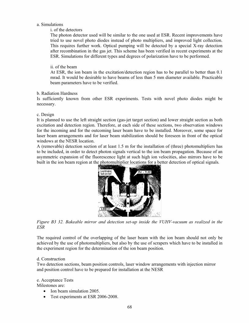
68
a. Simulations i. of the detectors The photon detector used will be similar to the one used at ESR. Recent improvements have tried to use novel photo diodes instead of photo multipliers, and improved light collection. This requires further work. Optical pumping will be detected by a special X-ray detection after recombination in the gas jet. This scheme has been verified in recent experiments at the ESR. Simulations for different types and degrees of polarization have to be performed.
ii. of the beam At ESR, the ion beam in the excitation/detection region has to be parallel to better than 0.1 mrad. It would be desirable to have beams of less than 5 mm diameter available. Practicable beam parameters have to be verified.
b. Radiation Hardness Is sufficiently known from other ESR experiments. Tests with novel photo diodes might be necessary. c. Design It is planned to use the left straight section (gas-jet target section) and lower straight section as both excitation and detection region. Therefore, at each side of these sections, two observation windows for the incoming and for the outcoming laser beam have to be installed. Moreover, some space for laser beam arrangements and for laser beam stabilization should be foreseen in front of the optical windows at the NESR location. A (removable) detection section of at least 1.5 m for the installation of (three) photomultipliers has to be included, in order to detect photon signals vertical to the ion beam propagation. Because of an asymmetric expansion of the fluorescence light at such high ion velocities, also mirrors have to be built in the ion beam region at the photomultiplier locations for a better detection of optical signals.
Figure B3 32. Bakeable mirror and detection set-up inside the VUHV-vacuum as realized in the ESR The required control of the overlapping of the laser beam with the ion beam should not only be achieved by the use of photomultipliers, but also by the use of scrapers which have to be installed in the experiment region for the determination of the ion beam position.
d. Construction Two detection sections, beam position controls, laser window arrangements with injection mirror and position control have to be prepared for installation at the NESR
e. Acceptance Tests Milestones are:
• Ion beam simulation 2005. • Test experiments at ESR 2006-2008.

69
• Design of detection section (2.phase: tests at ESR) 2007. • Design of laser installation 2007. • Acceptance test of detection section including test of the optical quality and UHV
requirements 2008. • Acceptance test of entrance window section including test of the optical quality and UHV
requirements 2009. • Completion of laser installation 2009.
f. Calibration Self calibrating, the experiment will result also in a reference value for the beam velocity
g. Requests for Test Beams A pre-stage of the experiment is proposed at the ESR. B 3 1.6.2 X-ray Laser Spectroscopy of Li-Like Ions
0,2
0,3
0,4
0,5
0,6
0,7
0,8
0,9
52 62 72 82 92
nuclear charge Z
η
14,7 nm13,9 nm12 nmrigiditycooler voltage
Figure B3 33. Excitation spectrum of lithium-like uranium. The 2s1/2 to 2p1/2 transition energy of 280 eV is within the range of laser-pumped X-ray lasers which will be capable of a reasonable repetition rate and intensity in the near future The photon energy is strongly shifted by the Doppler effect. This reduces the requirement for the X-ray laser.
X-ray laser spectroscopy of Li-like heavy ions is a promising tool to provide data on the charge radius and nuclear moments for a large variety of stable and radioactive isotopes. Due to the large Doppler shift the 2S – 2P transition in all Li-like ions up to Li-like uranium can be reached with state-of-the-art X-ray lasers (Figure B3 33). A prototype laser system in Ni-like zirconium was recently demonstrated at the PHELIX laser. Using the transient traveling-wave excitation scheme intense lasing was achieved at less than 5 J input energy, giving a perspective for pumping at relatively high repetition rate. a. Simulations
i. of the detectors The experiment requires the efficient detection of X-ray photons in the range between 100 keV and 900 keV. For this a special detection section of L ~ 1.5 m has to be designed, requiring extensive ray-tracing simulations. ii. of the beam

70
Requirements for the beam quality are: Diameter < 5 mm, divergence < 0.1 mrad . A specific problem of the NESR is the merging of the laser and ion beam, due to the still undefined supra-conducting dipole magnets. b. Radiation Hardness Background influence on the life time of the detector has to be studied
c. Design It is planned to use the left straight section (gas-jet target section) as both excitation and detection region. For this experiment, the X-ray laser beam has to be transported from the laser to the NESR in a vacuum tube. This has to be designed to fit together with the NESR dipole magnets. Considerable design effort has to go into the optimisation of the X-ray laser. Goal is the improvement of the beam quality and the repetition rate. d. Construction Set-up of the laser and the laser beam pass will require massive effort. Although a prototype laser at 56 eV was demonstrated at PHELIX, development towards higher photon energy and higher repetition rate is necessary. An international collaboration pursuing these goals has been formed.
Figure B3 34. X-ray laser set-up at PHELIX laser providing 56 eV photon energy. e. Acceptance Tests Milestones are:
• Ion beam simulation 2005 • Design of detection section (2.phase: tests at ESR) 2005 • Design and test of laser installation 2005 • Test experiments at ESR 2006-2008 • Acceptance test of detection section including test of the optical quality and UHV
requirements 2008 • Acceptance test of entrance window section including test of the optical quality and UHV
requirements 2009 • Completion of laser installation 2009
f.+g. Calibration and Requests for Test Beams Test beams have to be made available at the ESR (extracted beam in the "Re-injection tunnel", in front of the HITRAP experiment. B 3 1.6.3 Precision Laser Spectroscopy as a Test of Special Relativity An Ives-Stilwell experiment at NESR is expected to improve the upper limit for the time dilation test parameter α by two orders of magnitude to the 10-9 level. Beyond the kinematical test of special relativity these precision experiments at high velocity relative to the (apparent and dark) masses of our galaxy are unique for probing any velocity dependent mass change of the electrons in the fast moving ions.
71
a. Simulations i. of the detectors Not applicable
ii. of the beam A necessary precondition is the investigation of possibilities to prepare beams of applicable ion species in the new scenario. For the ESR, an experiment to prepare and accelerate singly charge Li-ions in the meta-stable state has been started. For the NESR the transport of such ions through SIS 100 to the NESR has to be studied. At ESR, the ion beam in the excitation/detection region has to be parallel to better than 0.1 mrad.
b. Radiation Hardness
Is sufficiently known from other ESR experiments
c. Design It is planned to use the left straight section (gas-jet target section) and lower straight section as both excitation and detection region as in the case of M1 spectroscopy. Additional space for laser beam arrangements and for laser beam stabilization should be foreseen in front of the optical windows at the NESR location. Furthermore, the implementation of the experiment into the NESR requires:
• The injection of two counter-propagating laser beams with high optical quality in at least one straight section. The two beams have strongly different wavelengths in the near-IR and the deep UV (120 nm).
• Control of the position and overlay of the ion- and laser-beam. • Insertion of at least two spatially separated detection sections into the straight section.
In addition a suitable arrangement for the preparation of an applicable low-charged ion beam has to be designed.After the choice of the ion to be used, the laser systems have to be designed
d. Construction Two detection sections, beam position controls, laser window arrangements with injection mirror and position control have to be prepared for installation at the NESR.
e. Acceptance Tests Milestones are:
• Ion and laser beam simulation 2005 • Test experiments at ESR 2005-2007 • Design of detection section (2.phase: tests at ESR) 2005 • Design and test of laser installation 2007 • Acceptance test of detection section including test of the optical quality and UHV
requirements 2008 • Acceptance test of entrance window section including test of the optical quality and UHV
requirements 2009 • Completion of laser installation 2009
f. Calibration Self calibrating, the experiment will result also in a reference value for the beam velocity
g. Requests for Test Beams A pre-stage of the experiment is proposed at the ESR. With this experiment specific issues concerning the high ion energy and the availability of ions in suitable metastable states have to be tested.

72
B 3 1.6.4 Interaction of Ultra-High Intensity Laser Pulses with Heavy Ions In highly charged ions the binding field is much higher than the field strength even the most intense lasers can produce. Nevertheless the electrons within the ion and the interacting electrons in the case of an additional external target are subject to strong accelerations. This means that processes that would normally saturate due to the inset of field-ionization will be allowed to reach into a new regime. In the case of the ion itself, this applies to the generation of high harmonics, limited only by the threshold of photoionization by the generated high-energy photons. An important factor, different to the situation at rest, will be the relativistic ion velocity. In the case of electron-ion collisions, the massive modification by the relativistic acceleration of the electrons will dominate the interaction characteristics. a. Simulations
i. of the detectors The photon detector used will be similar to the one used at ESR. Detectors for charge changed ions, electrons and other particles will be necessary. It is understood, that such detectors will be available. Particle trajectories have to be studied to verify usefulness. ii. of the beam The laser beam has to be focused to obtain ultra-high intensities. This requires entrance windows allowing entrance close to the beam with some small interaction angle. Optimum arrangement has to be verified.
b. Radiation Hardness The intense laser pulse can create EMI pulses when hitting surfaces. This has to be avoided by direct coupling into the vacuum.
c. Design It is planned to use the left straight section (gas-jet target section) and lower straight section as both excitation and detection region. Some space for laser beam arrangements and for laser beam focalization should be foreseen in front of the entrance sections at the NESR location. d. Construction Two detection sections, beam position controls, laser entrance ports with injection mirror and position control have to be prepared for installation at the NESR
e. Acceptance Tests Milestones are:
• Ion beam simulation 2005 • Design of detection section 2006 • Design and test of laser installation 2007 • Test experiments at EBIT 2005-2008 • Acceptance test of entrance section including test of the optical beam quality and UHV
requirements 2009 • Completion of laser installation 2009
f. Calibration not applicable
g. Requests for Test Beams The test will be done off-line at EBIT, after installation laser test at NESR without ion beam will be necessary.

73
B 3 2 Trigger, DACQ, Controls, On-line/Off-line Computing B 3 2.1 Electron Target The complexity of the trigger for the planned DR experiments is based on the complex multilayer integration of the ring components and of the detector signals and controls of the experiment. This can be easily demonstrated as follows: Synchronization signals from the CR and NESR kickers signal the beginning of a new stack. The cooling of the beam has to be signaled consecutively. During the stacking and during the cooling, the ramps for the next series of measurements are transmitted to the electron target controls. The algorithms to calculate the steps and the time windows of the ramps take into account the proper scanning of the expected resonances with emphases on relevant region of interest. After the beam is cooled, the HV of the electron target is swept accordingly, and its values—checked for consistency—are nothing but the relevant abscissa of the measurement. The ordinate is given by the number of particles that were Bρ-analyzed by the next NESR dipole section and detected by a particle detector, which is part of the ring ancillaries. Every step of the ramp is time-differentially normalized to the ion intensity, measured by the NESR ion-current transformer and/or by the residual gas position monitor used as a SEETRAM. The values are double-checked by the rate of ions that have captured one electron in the main cooler, corrected by the background measured with the particle detectors after the other dipole sections. Note that the trigger is a combination of deterministic and stochastic signals and that some of the signals are pertinent to a second-level trigger. A comprehensive example of such a signal is the FFT of a Schottky noise, where the time needed fore a record is unequivocally given by the Fourier's inequity. In other words, the trigger, DACQ, and the controls of the measurement are to a high and complex degree interlaced with the accelerator controls. Thus, the future development of the accelerator controls should be done in close collaboration with the experiments in order to define and standardize interfaces, protocols, campus timing and standard system time stamps, as well as master-slave relations of the particular subsystems. B 3 2.2 Internal Target The internal target should provide gate/veto signals for the experiments which reflect the status of the jet. In addition information about the jet density should be provided. Also into should be possible to have a event controlled target operation, events defined by the NESR operation. B 3 2.3 Photon Spectroscopy
Crystal Spectrometers for Soft and Hard X Rays Electronics and computing demands for spectrometer controls are very moderate. Resources are mainly needed for the operation of several two-dimensional germanium strip detectors. The necessary effort will be specified below. The X-rays are measured in coincidence with ions having lost one charge unit in the beam–gas interaction. Therefore an operating particle detector is needed.
Calorimeter DSP based DAQ have already been developed by the Cfa and the Mainz detector groups and adjusted for the characteristics of the individual calorimeter systems. X-ray optics for photon spectroscopy Standard electronics and DACQ systems as well as computing facilities, which are/will be available at GSI/FAIR are required
µ-Strip Solid State Detectors for the operation of the µ-strip solid state detectors it is planned to process 128 channels (strips) of the individual detector system. The electronic readout will be based on a VME system (ADC, TDC
74
and CFT) using in addition NIM amplifiers and fast amplifiers with high integration density (16 channels per module). The settings of the amplifiers, pre-amplifiers and CFT modules will be managed by slow controls. Currently, one prototype system is already in preparation at GSI. In addition, data transfer and processing will be based on the MBS system developed at GSI. Slow controls are required for the HV settings/control as well as for liquid nitrogen filling and temperature controls. For the latter a Labview based control system will be used. Polarimeter for Hard X-rays Polarimetry and imaging in the hard X-ray regime based on segmented strip detectors with a pitch of 2mm it is desired to develop a pulse shape sensitive data acquisition system allow to improved the position sensitivity ab at least a factor of 4 compared to crystal segmentation. The latter required both hardware and software development. The system to be developed will be based on the fast, continuous sampling of the detector signals and on the on-line digital signal processing. This system is modular and allows for easy scaling. A 16 channel board is the basic unit and a first prototype is already available. Each read-out channel is composed of an amplifier, an analogue to digital converter and a memory. The digital data are sent with one multi-wire cable from all boards to the DSP-based VME module. The DSP runs an algorithm allowing for measurement of interesting physical parameters, e.g. energy, time, and the position of the absorbed photon. Thus, it is possible to reconstruct, with high resolution, a three dimensional event in the detector volume. The data are then accessed from the VME crate controller to be stored on disk.
Features:
• Read-out electronics mounted on the detector • 12-bit ADC for each detector channel, • Low noise pick-up, • Low channel to channel cross talk, • Modular construction based on 16-channel board, • Multi-level buffering, fast data taking, • Fast digital data transport from the detector to the VME crate, • On-line data processing by the DSP in the VME module, • Low cost per channel,
The new read-out idea is based on the continuous sampling of the detector output signals. Front-end pre-amplifiers connected directly to the Ge detector remain beyond the scope of the project. Output signals from the pre-amplifiers are the input signals to the proposed system. The system is located as close to the detector as possible. The LEMO type coaxial cables connecting the front-end to the inputs are short (less than 1m) and have low capacitance. When the trigger signal appears, a pre-defined number of digital samples taken before and after the trigger signal is stored in the FIFO [First In First Out] memory in each channel. The proposed sampling frequency is 64 MHz – thus a sample is taken every 15.625 ns. The number of samples collected in the FIFO memory associated with a given trigger is defined by the length of the time window selectable the the user. The length of the time window is in the range of 0.1 to 4 µs.
B 3 2.4 Electron Spectrometer at the Internal Target This experiment will use standard electronics, control of jet target, cooler signal, bunch signal, charge changing detectors, general machine operation signals. B 3 2.5 Extended Reaction Microscope In experiments with the extended reaction microscope low energy electrons with multiplicities between 1 and 6, recoiling target ions, X-ray photons and charge changed projectiles will be measured in coincidence. Particle detectors for projectiles having lost or captured an electron are thus needed in a location following the first main dipole behind the super sonic target. a) Low Energy Branch of the Extended Reaction Microscope

75
For experiments conducted only with the Low Energy Branch of the Reaction Microscope standard electronics and data acquisition systems and computing facilities as are available at GSI will be required. Two 2D position sensitive multihit capable detectors for electrons and recoiling target ions and a pixel-segmented X-ray detector will be operated simultaneously. The electronic signal readout will be based on standard VME systems complemented by standard NIM electrons. It is planned to base the data processing and transfer on the MBS system developed at GSI. b) Imaging Forward Electron Spectrometer Branch of the Extended Reaction Microscope Electrons emitted in the forward direction with vElectron ≈ vProjectile will be separated from the coasting beam in the NESR by the first dipole magnet. It has been shown with the current ESR spectrometer that the already very small effect of the dipole magnetic field on the coasting beam can be compensated very well by two deflectors. B 3 2.6 Laser Experiments For all pulsed laser-ion interactions, a phase-sensitive synchronization between the circulating ion bunch and the laser pulse is mandatory. Concepts for this synchronization with short pulse lasers are currently developed in the context of the PHELIX project and are well-known from ESR laser experiments. Detector signals are gated with respect to the laser timing and the NESR working conditions. For this a common system for timing and data transfer has to exist, similar to the situation at the ESR. B 3 3 Beam/Target Requirements a) Beam specifications: The major interest of the planned experiments will be focused on intense and cooled beams of high-Z heavy and stable nuclides in defined ionic states. Some of the planned studies will require exotic beams produced via projectile fragmentation or projectile fission, analyzed and separated by the Super FRS (SFRS). Another class of experiments will deal with antiprotons. The particles will be cooled down to a coasting beam. In various cases (laser, TOF experiments, etc.) bunched beams with well-defined bunch structure as well as with reduced number of bunches will be required. This is also of advantage for the planned fast extraction. The electron cooling should be optimized with respect to the losses due to electron capture in order to produce brilliant beams with an optimal low emittance and with an optimal lifetime. Of special interest will be an excellent definition of the beam velocity on an absolute scale. This has to be achieved by detailed knowledge of the electron cooler, based on precise calibration of its high voltage, space charge, contact potentials, etc. . In addition, the position of the beam will be very important for precise experiments with or without lasers. Strategically positioned moveable scrapers as well as position sensitive residual gas monitors will be required by various experiments. The cooling velocity and the position definition have to be accompanied by a high-resolution Schottky noise fast Fourier transformation (FFT). For the experiments with the second electron target, the ion beam has to be aligned with the electron beams in both coolers. Additionally, the ion beam should merge as concentrically as possible with the electron beams. This requires not only diagnostic tools for the revolution frequency and for the ion beam position but also active elements such as pairs of steerers that will allow eliminating potential misalignments. In some cases, two or more isotopes and/or charge states will be stored simultaneously, one of them for calibration purposes. In addition, some exotic beams can be recycled, if the ions that have captured an electron are kept in the NSR acceptance and—after a sizeable amount of them is accumulated—are accelerated in a short cycle to higher energies where the captured electron can be stripped by passing through the gas-jet target. On the other hand, some measurements of exotic Li and Be-like ions will have to use the electron cooler to breed the higher charge states of exotic species that will be produced at high energies in SFRS. The energy of the beam will vary from very high to a decelerated one, down to four MeV/u. The high energy will be required to strip effectively the K-electrons in the high Z-ions whereas the lowest ones are best suited for minimizing the Doppler shift and broadening. All experiments will

76
require an exact definition of the ion current. For the higher intensities, a transformer similar to the presently used at ESR and at SIS will be necessary. For the lower intensities, new methods are to be developed, for instance SEETRAM-type detectors that make use of the ionization of the residual gas. The planned residual gas position sensitive monitors should be further developed to serve this purpose as well. This is of utmost importance for all multiscaling experiments, especially for the investigations of rare radioactive species. b. Running Scenario The atomic physics experiments at NESR will use both stable ions from SIS100 as well as radioactive exotic beams produced by projectile fragmentation and/or fission and selected by Super FRS. In some experiments, more than one nuclide and/or isotope that fit the acceptances of CR and ESR will be injected. The SIS energies will be optimized with respect to the optimal velocity to produce the charge state of interest, with respect to the production cross section for the fragments of interest, and with respect to the resulting beam emittance and ion-optical settings. We assume that — in analogy to SIS18 — the SIS100 bunches will be combined, and one single fast extracted SIS100 bunch will fill the rings up to their space charge limit. If fragments are produced in Super FRS, they will be stochastically cooled in CR prior to injection into NESR. Since electron cooling is needed, the lower limit for the lifetimes of exotic species is usually in the region of a few seconds. The electron cooler will usually cool the injected ions first. The ion and electron beams have to be aligned collinearly in the solenoid section at the beginning of the run. The cooling intensity will be optimized with respect to the anticipated momentum spread of the ions and to the lifetime of the beam due to atomic ion capture. With a UHV of 10-11, the energy loss and the lifetime reduction due to interactions with the residual gas molecules should not play a significant role. After the cooling is completed, fast pneumatic actuators will bring the particle and gamma detectors, the slits and scrapers in position. The positions have to be adjusted at the beginning of the run. Depending on the experiment, the gas jet will be turned on or the electron target will start its ramping. The overlap of the ion beam with the gas jet has to be adjusted at the beginning of the run. It is obvious that the actuators have to be fast in order to start the productive part of the measurement with a minimum delay. The majority of the experiments will require injection repetition rates as low as one injection per minute (or longer) and the measurements will be performed with the stored beams. Their intensity decreases mainly due to electron capture in the cooler or due to ionization/capture in the gas jet target. The ion beam intensities have to be monitored in a nondestructive way by an ion-current transformer for higher beam intensities and by other detectors for currents lower than several µAmps. Most notably the laser experiments will need a bunched beam. In such cases, the length of the bunch is expected to be rather short. Special care should be taken to optimize the electron cooling as a function of the ion intensity. Most of the laser experiments require an overlap of the ion and the laser beams. For this, special scrapers will be available. The DR experiments require co-propagating electron and ion beams in the solenoid sections of both main cooler as well as of the electron target. This has to be adjusted by using the position monitors and measurements of the revolution frequency by means of Schottky noise analysis. NB, the Schottky noise analysis is a diagnostic tool for all experiments. The beam time will be organized in three to four blocks of two to three weeks per year. In each block, several experiments will be performed. For instance, in one block a DR measurement will use the first 5 to 6 days, followed by a week of X-ray measurement at the gas target. At that time, the
77
electron spectrometers can start taking data as well and continue in the last few days with a dedicated experiment. Since the rings will be filled once per minute or even once per several minutes, the NESR experiments will need only a small portion of the SIS100 time. B 3 3.1.1 Electron Target The basic requirements for the NESR-electron target have been elaborated in more detail in sections B 3.1 and will be stressed here as follows: • Maximal sustainable high voltage of the electron target is 40 kV. • The envisaged maximal electron current is 1 A. • The envisaged maximal diameter of the electron beam is 3 cm. • The maximal solenoid field required is 0.2 T. • The planned adiabatic expansion of the guiding magnetic field by a factor of 20 would lead to
transversal temperatures of T⊥ ≅ 5 meV. • For the gun section a superconducting magnet of 4 T is needed. • Longitudinal temperatures of T|| ≅ 0.01 – 0.03 meV after adiabatic acceleration are envisaged. • The height of the acceleration section could reach 8-9 meters above ion beam pipe. This results
in a total height of 10-11 m above the floor. Therefore, an additional tower will be needed for the gun section.
• The radius of toroid curvature will be below 2 m. • A length of 4 m for the solenoid section is envisaged. • A linearity of the straight section of better than 0.1 mrad seems to be feasible. • The ion beam has to be parallel to the electron beams in the cooler and in the electron target. • Diagnostic tools for the electron and ion beams in the electron target and in the cooler are
needed. B 3 3.1.2 The internal jet target The demands of the EXL collaboration are basically densities for light targets such as H2 and He of about 1014 /cm2 to 1015 /cm2 whereas the requirements for atomic physics are more relaxed and the desired areal densities for light as well as for heavy targets are of the order of 1012 /cm2 for the heavier gases and 1012 /cm2 to 1014 /cm2 for the light targets. On may also note that both collaboration are requesting a (possibly variable) jet target diameters in the range of 1 to 5 mm. The 1 mm option is essential for various experiments. To what extend both requirements (1014 /cm2 @ 1 mm target diameter) are compatible needs further investigations. B 3 3.1.3 Photon Spectroscopy Crystal Spectrometers for Hard and Soft X Rays For the spectroscopy experiments at the gas-jet target a stable cooled ion beam with a momentum spread in the order of ∆p/p=10-4 is sufficient. An independent measurement of the beam velocity is mandatory. A nitrogen gas jet with a density of about 1012 cm-3 and a diameter of about 5 mm is required. Calorimeter Beam specification of the calorimeter experiments are basically identical to the experimental studies based on crystal spectrometer systems. The operation of calorimeter for X-rays spectroscopy would profit considerably from a small target beam diameter of about 1 mm. The would significantly reduce the Doppler broadening and would therefore guarantee for a higher flexibility with respect to geometrical constrains at the internal target. Typically, distances of as close as 10 cm to the ion beam/target interaction point would be desirable. Also one the target environment should allow the positioning of such detectors not only at 900 but I particular in the forward hemisphere e.g. at 300.

78
X-ray optics for photon spectroscopy Both for tests as well as for running the planned atomic physics experiments the intense and cold decelerated ion beam of fully stripped uranium ions (U92+ ) as well as H-like (U91+ ) and He-like (U90+) at the NESR will be required . These beams have to be cooled at the electron cooler. At the internal gas target a jet of light noble gas will be used to produce REC X-rays which will be focused, using polycapilary X-ray optics or multilayer focusing X-ray lens, on the high-resolution microcalorimeter detector. Polarimeter for Hard X-rays For hard X-ray polarimetry, standard operation of the internal target is planned (target species: H2 to Xe) . For the application to polarized ion beams, a bunched structure for the cooled and stored ion beams is desirable. In this case the experiment would also rely on a dense H2 target.
Electron Spectrometer at the Internal Target For the experimental concerns following beam specifications are requested: focus ≤ 2x2 mm, intensity: ≈108/ spill, beam species: H-like 155Gd63+ , 195Pt77+, 212Bi82+, 228Th89+, …bare nuclei selected and Coulomb excited (merged beam, e- collider, internal target) , beam energy: Emin…Emax , CW - mode energy spread: δEp / Ep ≤10-4 (cooler operation).
Extended Reaction Microscope The extended reaction microscope with the imaging forward electron spectrometer requires aereal target densities for light targets (H2, He) up to 1013-14/cm2; similar values are desirable for heavier targets (N2, Ne, Ar, Kr). In order to achieve the intended position and resulting momentum resolution for the collision products a geometrical size of the jet corresponding to a diameter of favourably 2mm but not exceeding 5mm is required. Beam cooling is needed to keep the momentum spread below 10-4 .The beam diameter at the target location is desired to be ≈ 2 mm diameter with less than 1 mrad divergence. Laser Beam specifications: (focus, intensity, halo tolerance, beam species, beam energy, Spill Length, CW or pulsed mode. For most of the spectroscopic experiments, the beam has to be unfocused for the length of the interaction region. The beam diameter should be less than 2 mm. The relative beam velocity variations have to be better than 10-5. For the interaction at ultra-high intensities, a smaller beam diameter is necessary. b) Running scenario including exemplary beam time planning in a year: Test beam time of 4 days will be taken in combination with selected X-ray measurements. The program will be defined harmonized with other user aspects (X-rays, recoil ions,..) in order to exploit maximum information. According to the large effort necessary to prepare the laser systems, beam alignment and the detector suite, a typical laser experiment should not be shorter than 1 week. During this period a program with different ion charge states or beam energies should be possible. Sharing of the beam with other experiments at the NESR might be acceptable. Each experiment should have at least one beam time every 2 years, requiring about 3 weeks of beam time per year for this group of experiments.

79
B3 4 Physics Performance B 3 4.1 Electron Target The two main objectives of the dielectronic recombination (DR) experiments with the new NESR electron target are: (i) precise studies of ionic structures with an emphasis on QED-Effects and (ii) studies of the nuclear properties—such as isotope shift—with atomic physics methods. The first case will focus on H-like and/or on few electron high-Z ions, such as Li-like ones. The second physics case will focus on Li and Be-like chains of heavy isotopes; both stable as well as long-lived ones (> 10 sec). As an example the potential of this method has been investigated recently (August 2005) in a first pilot experiment studying the isotopic shift of Li-like 142Nd57+ versus 150Nd57+. As depicted in Figure B3 35, already the preliminary data show a clear pronounced shift of the DR resonances studied. The data are currently subject of a detailed analysis [Ko05].
Figure B3 35. Preliminary results of a DR-measurement with Li-like Nd-isotopes. The observed energy shift of the DR-resonancies reflects the isotopic shift (volume effect) for Li-like 142Nd57+ and 150Nd57+ [Ko05].
Common for all of the planned measurements is the very high detection efficiency: All ions, which have captured an electron in the cooler and which stabilize promptly via emission of X-rays, continue almost undisturbed their flight in the ring and will be separated by the next dipole magnet from the main beam. A particle detector placed in (or after) the magnet will detect them with practically 100% efficiency. Common for all the experiments is also the multiscaling method of measuring spectra: The spectral range of interest is scanned repeatedly up and down in small steps that are usually smaller than the width of the response function of the apparatus. A 'multiscaling' beam-time reduction factor has to be taken into account when planning an experiment. The reduction factor equals the ratio of the spectral range of interest and of the width of the response function. It should be very strongly emphasized that a narrow response function is of utmost importance. It is vital to have very cold electron and ion beams at well-defined energies as planned for NESR. This alone would lead to an extremely good performance of the anticipated measurements of DR resonances, their positions, areas, and line shapes. Additionally, the good energy resolution due to the low beam temperature will be boosted by the co-propagating kinematics of the electron and ion beams. This can be seen in Figure B3 36. The upper part of it shows the energy in the c.m. system as a function of the electron-ion energy difference in the lab. i.e. as a function of the applied high voltage for the electron target that leads to an energy difference with respect to the main cooler electrons. The left hand part shows the low collision energy scenario. As can be seen, several kV have to be applied in the laboratory in order to arrive at electron-ion collision energies of few hundred eV. This is a very big advantage of the method, as can be seen in the lower left part of the picture: Here, the
0.8 1.0 1.2 1.4 1.6 1.8 2.0 2.2 2.4 2.6 2.8 3.0
100
200
300
400
500
Rat
e C
oeffi
cien
t [Ar
b. U
nits
]
Electron-Ion Collision Energy (c.m.) [eV]
A=142 A=150
Nd56+ (1s2 2p1/2 18lj )
n = ∞n = 18
2p1/2
2s1/2
...
preliminary

80
energy spread in the c.m. system divided by the energy spread in the lab system is shown also as a function of the electron-ion energy difference in the lab. To illustrate the advantage, a rather normal high voltage power supply of the 0.01% class could be considered. At 5 kV, the HV-uncertainty in the lab will run to the rather large value of 0.5 Volts. In the c.m. system, however, this will lead to a sub eV spread of less than 0.05 eV. As can be easily seen, the situation becomes better and better the lower the c.m. energy is. For the high-energy scenario presented on the right hand side of the figure, the motional boost of the resolving power vanishes. It should be noted, however, that these energies are needed to study the KLL, KLM, KLN, etc. resonances in high-Z ions, where the natural line widths become as high as e.c. 35 eV for uranium.
Figure B3 36. The center of mass energies of the electron-ion colliding systems are shown as a function of the electron target high voltage, i.e. of the difference in the laboratory kinetic energies of the target electrons and of the main cooler electrons. The lower part shows the energy spread in eV in the c.m. system per one eV energy uncertainty in the lab system also as a function of the electron target high voltage (see text for additional information).

81
Figure B3 37. Energy spread due to the transversal and longitudinal electron temperature as a function of the c.m. collision energy.
The energy spread in the c.m. system for the present ESR cooler is compared to the one expected for the separate NESR electron target in Figure B3 37. Due to the planned adiabatic expansion (green curve), very low c.m. energies will be accessible, and the energy resolution (and/or sensitivity) there will be at least an order of magnitude better than the present one (the latter being also remarkably good.) It is also visible that the adiabatic acceleration is needed as well, since the longitudinal temperature starts playing a role at relatively low c.m. energies. At even higher collision energies the ion beam temperature also starts dominating the resolution (blue line for dp/p = 10-5). Since the ion-beam temperature can be decreased by decreasing the ion beam intensity, future experiments with very good resolution will be carried out as well. Note that a measuring cycle starts with a high ion beam intensity, which decreases exponentially in time. Thus, at high collision energies the cycles can be prolonged in order to include low-intensity low energy spread measurements at the end of each NESR filling. Solely the fact, that ionic structure can be scanned with sub eV precision by detecting heavy ions at relativistic velocities with no photons in sight is worth mentioning again. The count rate estimates are based on the maximal electron current of 0.5 A, on an effective electron target length of 4 m, and on a multiscaling reduction factor of 1000. The figure of merit for the low collision energy case is that 104 heavy exotic particles are needed in order to measure sub eV isotopic shifts with reliable statistics in a run of three days. The anticipated measurement of QED interferences in overlapping resonances at high energies will take longer, since the cross sections in this case are significantly smaller. One to three weeks of measurement have to be planned, depending on the required resolution. As usual, the ion beam does not have to be injected constantly, since stable or long-lived ions can be stored and studied for several minutes.
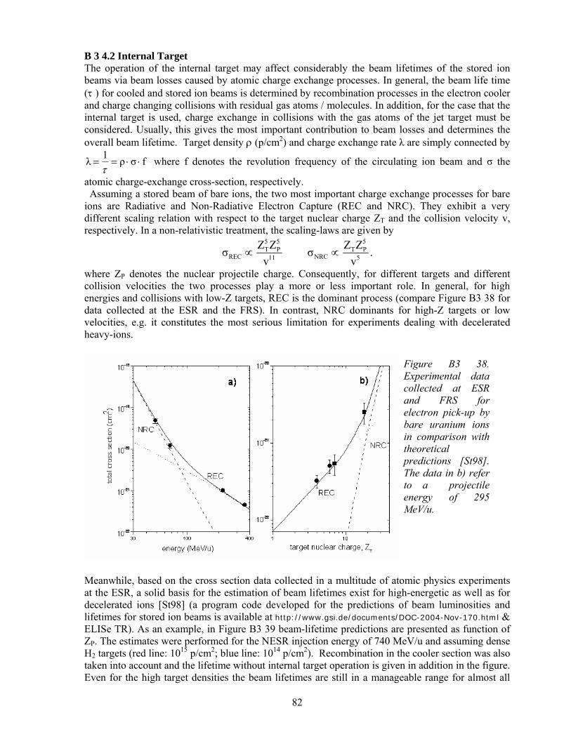
82
B 3 4.2 Internal Target The operation of the internal target may affect considerably the beam lifetimes of the stored ion beams via beam losses caused by atomic charge exchange processes. In general, the beam life time (τ ) for cooled and stored ion beams is determined by recombination processes in the electron cooler and charge changing collisions with residual gas atoms / molecules. In addition, for the case that the internal target is used, charge exchange in collisions with the gas atoms of the jet target must be considered. Usually, this gives the most important contribution to beam losses and determines the overall beam lifetime. Target density ρ (p/cm2) and charge exchange rate λ are simply connected by
fσρ1 λ ⋅⋅==τ
where f denotes the revolution frequency of the circulating ion beam and σ the
atomic charge-exchange cross-section, respectively. Assuming a stored beam of bare ions, the two most important charge exchange processes for bare ions are Radiative and Non-Radiative Electron Capture (REC and NRC). They exhibit a very different scaling relation with respect to the target nuclear charge ZT and the collision velocity v, respectively. In a non-relativistic treatment, the scaling-laws are given by
.vZZσ
vZZσ 5
5PT
NRC11
5P
5T
REC ∝∝
where ZP denotes the nuclear projectile charge. Consequently, for different targets and different collision velocities the two processes play a more or less important role. In general, for high energies and collisions with low-Z targets, REC is the dominant process (compare Figure B3 38 for data collected at the ESR and the FRS). In contrast, NRC dominants for high-Z targets or low velocities, e.g. it constitutes the most serious limitation for experiments dealing with decelerated heavy-ions.
Figure B3 38. Experimental data collected at ESR and FRS for electron pick-up by bare uranium ions in comparison with theoretical predictions [St98]. The data in b) refer to a projectile energy of 295 MeV/u.
Meanwhile, based on the cross section data collected in a multitude of atomic physics experiments at the ESR, a solid basis for the estimation of beam lifetimes exist for high-energetic as well as for decelerated ions [St98] (a program code developed for the predictions of beam luminosities and lifetimes for stored ion beams is available at http://www.gsi.de/documents/DOC-2004-Nov-170.html & ELISe TR). As an example, in Figure B3 39 beam-lifetime predictions are presented as function of ZP. The estimates were performed for the NESR injection energy of 740 MeV/u and assuming dense H2 targets (red line: 1015 p/cm2; blue line: 1014 p/cm2). Recombination in the cooler section was also taken into account and the lifetime without internal target operation is given in addition in the figure. Even for the high target densities the beam lifetimes are still in a manageable range for almost all

83
projectile charges. Also one may add that the most important loss process at high energies, i.e. REC, can be exploited as a beam luminosity monitor (for this process a remarkable agreement between experiments and theory exists). Note that basically 80% of the REC events populate the projectile groundstate leading to the emission of monochromatic high-energetic photons which can easily be detected. Also the relativistic forward boost of the emission is - in the case of REC transitions - cancelled by retardation effects. Therefore, even at relativistic energies a considerable amount of photons will be detectable at backward angles or at 900.
0 20 40 60 80 100101
102
103
104
105
electron cooler
cooler +jet [1015 p/cm2]cooler +jet [1014 p/cm2]
beam
life
tim
e [s
]
nuclear projectile charge, Z
Figure B3 39. Beam lifetime estimates as function of ZP. The estimates were performed for the injection energy of 740 MeV/u, assuming dense H2 targets (red line: 1015 p/cm2; blue line: 1014 p/cm2). In addition recombination in the cooler section was taken into account. A lifetime for NESR operation without internal target is given in addition.
In the following some basic considerations are given, in particular relevant for X-ray experiments and collision studies using the internal target. These considerations refer to heavy bare, H- or He-like ions only. • High-energies (above 150 MeV/u) and low-Z targets: REC is the most important charge exchange
process, populating predominantely the groundstate of the ions. Due to the relatively small capture cross-section the beam lifetimes are only moderately affected. For X-ray experiments relatively high target densities are needed, e.g. 1013 p/cm2, in order to collect sufficient statistics. Here the use of hydrogen as a target gas has the advantage of having a small Compton profile. Moreover, this energy range is in particular well suited for polarization studies of the REC process.
• Energies (50 to 150 MeV/u): Due to the relatively moderate Doppler broadening, this energy
range is of particular relevance for X-ray spectroscopy (L →K) transitions. For this purpose a nitrogen or an argon target provides favourable conditions. Here NRC is the dominant capture process, favouring the population of excited projectile states which results in a strong emission of characteristic projectile X-ray. One can expect to produce up to 1011 Ly-α photons per day (106 per second) emitted into 4π. The target densities to be used are typically of the order of 1012 p/cm2
and the beam lifetimes in the range between 30 s and 2 minutes (compare Figure B3 40). • Energies below 50 MeV/u: The strongly enhanced capture cross section at low-collision energies -
in particular when dealing with heavy targets - favours the use of an hydrogen target. For energies below 10 MeV/u, a hydrogen target with densities in the order of 1012 p/cm2 is mandatory. Beam lifetimes are typically below 30 s.
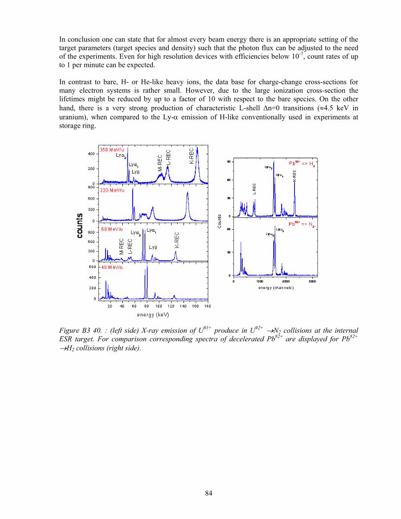
84
In conclusion one can state that for almost every beam energy there is an appropriate setting of the target parameters (target species and density) such that the photon flux can be adjusted to the need of the experiments. Even for high resolution devices with efficiencies below 10-7, count rates of up to 1 per minute can be expected. In contrast to bare, H- or He-like heavy ions, the data base for charge-change cross-sections for many electron systems is rather small. However, due to the large ionization cross-section the lifetimes might be reduced by up to a factor of 10 with respect to the bare species. On the other hand, there is a very strong production of characteristic L-shell ∆n=0 transitions (≈4.5 keV in uranium), when compared to the Ly-α emission of H-like conventionally used in experiments at storage ring.
Figure B3 40. : (left side) X-ray emission of U91+ produce in U92+ →N2 collisions at the internal ESR target. For comparison corresponding spectra of decelerated Pb82+ are displayed for Pb82+ →H2 collisions (right side).

85
B 3 4.3 Photon Spectroscopy Crystal Spectrometers for Hard X Rays (30–120 keV) A detailed account of the spectrometer parameters and of the systematic test results are given in reference [Be04]. In Figure B3 41 representative X-ray spectra from a 169Yb source are displayed recorded in scanning mode or with a germanium strip detector. Table B3 3 shows the observed line widths to be in good agreement with the theoretical estimate. This is a proof for the control over the crystal parameters. The measured detection efficiency turned out to somewhat exceed the prediction based on Monte Carlo ray-tracing calculations (see Figure B3 42) . Despite the low efficiency it was shown that precision measurements will be feasible at the ESR with the spectrometer parameters chosen. In Figure B3 43 the Lyman-α spectrum of hydrogen-like Au78+ is displayed. This spectrum was obtained with one FOCAL spectrometer in a test experiment at the ESR showing the feasibility of the experiment. With the advancing detector developments it will be possible to choose smaller line widths in the future by utilizing modified crystal parameters.
Figure B3 41. Test spectra recorded with FOCAL in scanning mode (top) or with a germanium strip detector (bottom).
Table B3 3. Calculated and observed line widths, in eV, for the FOCAL crystal spectrometer. The tests were made in scanning mode.

86
Crystal Spectrometers for Soft X Rays (3–20 keV) Using a decelerated and cooled ion beam in the NESR a primary rate of a few times 107 photons per minute may be expected both at the gas-jet target and at the electron target or cooler when adjusting the gas density or the electron current such that cycle times of typically 2 minutes are realized. With the planned X-ray spectrometers an efficiency of a few times 10-7 may be accomplished. Based on these assumptions a rate of more than one event per minute can be expected. Within a reasonable beam time of about one week systematic effects will limit the accuracy rather than counting statistics. Although details have to be worked out by means of the planned simulations one can conjecture that the X-ray lines can be located to within ±0.05 eV. For the present applications it is essential to have a supply of high quality crystals which are well characterized. The X-ray Optics Group of Jena University has long-term experience in preparation, test and use of cylindrical, spherical and toroidal crystals with curvature radii from 0.1 m to 1m. About 200 bent crystals have been produced by a replica technique [Fo91]. Characterisation of bent crystal perfection is e.g. shown in Figure B3 44 for a cylindrical crystal. Angular misorientation along a central surface line of the cylindrically bent quartz is an order of magnitude smaller than for commercially available quartz, both used in reflection 10-10. Spectral resolution of 10000 in X-ray spectrometers equipped with 1-D or 2-D bent crystals can be reached as shown in simulations of X-ray spectroscopy of laser produced plasmas [Re04].
X-ray optics for photon spectroscopy The X-ray optics developed for the atomic physics experiments at the NESR, combined with high-resolution X-ray spectrometers (microcalorimeter, crystal spectrometer), will result in substantial increase of measured event rate, giving thus an access to measure with high precision fine structures
Figure B3 42. Measured (data points) and calculated (curve) detection efficiency for one reflection in a FOCAL spectrometer with the parameters given in the figure and normalized to a detector width of 100 mm.
Figure B3 43. Spectrum of the Lyman-a lines of hydrogen-like gold recorded during a test experiment at the ESR.
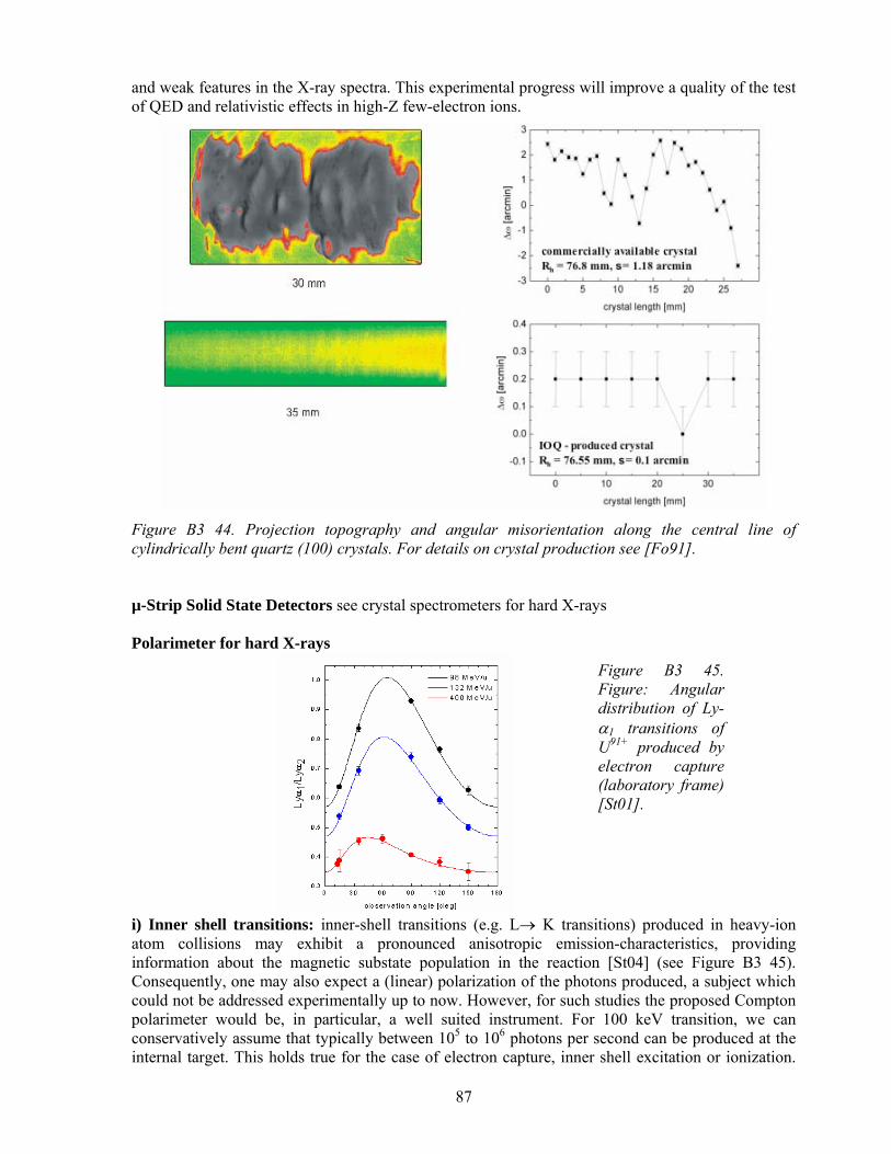
87
and weak features in the X-ray spectra. This experimental progress will improve a quality of the test of QED and relativistic effects in high-Z few-electron ions.
Figure B3 44. Projection topography and angular misorientation along the central line of cylindrically bent quartz (100) crystals. For details on crystal production see [Fo91]. µ-Strip Solid State Detectors see crystal spectrometers for hard X-rays Polarimeter for hard X-rays
Figure B3 45. Figure: Angular distribution of Ly-α1 transitions of U91+ produced by electron capture (laboratory frame) [St01].
i) Inner shell transitions: inner-shell transitions (e.g. L→ K transitions) produced in heavy-ion atom collisions may exhibit a pronounced anisotropic emission-characteristics, providing information about the magnetic substate population in the reaction [St04] (see Figure B3 45). Consequently, one may also expect a (linear) polarization of the photons produced, a subject which could not be addressed experimentally up to now. However, for such studies the proposed Compton polarimeter would be, in particular, a well suited instrument. For 100 keV transition, we can conservatively assume that typically between 105 to 106 photons per second can be produced at the internal target. This holds true for the case of electron capture, inner shell excitation or ionization.

88
Furthermore, assuming a distance of about 20 cm between detector and target we obtain a solid angle of about 7x10⁻³ of 4π (active area of the detector: 3600 mm2). Thus, we expect an average rate of 10 to 100 events per second. Even for a worst case estimate, assuming that for only 10% of the absorbed photons the Compton recoil electron and the Compton photon will be detected, a still sizable fraction of about 1 to 10 photons per second can be analyzed with respect to their polarization.
Figure B3 46. Normally, in photoionization the photo-electron is ejected into the direction of the electric field vector of the photon wave. For high photon energies, however, it has been predicted that the electron is preferentialy emitted along the magnetic field vector.
ii) Recombination transitions (REC transitions to the ground state, photon energy between 250 keV and 500 keV): In former experimental studies where a 4x4 pixel detector with an area of 780 mm2 was used, it was found that a beam time of about 1 day was necessary to obtain a meaningful result [Ta04,Ta05,St04]. For comparison, we expect for the proposed detector system an increase in efficiency by more than a factor of 10 (not taking into account the larger active area of the new system). This should allow to conduct such a measurement at one particular observation angle within 1 hour. One particular topic to be addressed would be the so called cross over effect (compare Figure B3 46). It is predicted that at high energies and forward angles the photon polarization changes its sign (Figure B3 47). For the time-reversed situation this would mean that the photo-electron produced is no longer ejected in the direction of the electric field vector but in the direction of the magnetic field vector of the ionizing photon wave; an effect not observed up to now but of great relevance for high-energetic photon matter interaction. iii) Beam polarization studies by means of REC: For this application the same transitions as discussed in ii) will be exploited. Here it will be important to detect a rotation of the polarization plane with respect to the scattering plane [Su05]. Again the instrument should allow - within a relatively short time of about 1 to 3 hours - to measure such a rotation with an accuracy of about 10. However the question how to polarize the ion beam must be addressed (see also [Pr03]). Because within the first stage of the FAIR development a polarized hydrogen target is not planned, we will try to apply optical pumping of the upper hyperfine level in H-like 207Bi in order to transfer the electronic polarization to nuclear polarization. Whereas this polarization scheme is believed to be very effective, the question on how beam polarization is preserved in the ring deserves detailed investigation. Of course this question will also be answered by this proposed experiment itself. Note, such investigations are of key relevance for experiments under discussion aiming for an investigation of parity violation effects in high-Z He-like ions.

89
Figure B3 47. Figure: Predicted linear polarization for REC into bare uranium at various collision energies: black line 20 MeV/u; dotted blue line 400 MeV/u; dashed red line 760 MeV/u.
B 3 4.4 Electron Spectrometer at the Internal Target The experiments will start with the operation of the transport magnet together with a solid detector, achieving a solid angle of 1,5% in the laboratory frame with an energy resolution of ≈ 0,1%. This gives an outline on the total electron emission from collisional continua to discrete projectile electron lines (Auger, conversion), complementary to X-ray decay studies. Gas target densities of 1011 up to 1014 atoms/cm2 and 109 stored projectiles will be used reaching luminosities of L~1,6 x 1029/cm²s. Accordingly a source rate of 1,6 x 10⁵/s results for cross sections of 1 barn. This cross section applies for the considered conversion channels from nuclear Coulomb excitation and also for relatively weak atomic reaction channels (e- capture, electron excitation and ionization processes) which, in particular cases, are often several orders of magnitude larger. For applying the high resolution measurement with a small instrumental acceptance of ≈10-6, a count rate of ~0,16/s can be expected for a cross section of 1 barn. The enhancement of solid angle transformation from the cm- into the lab –system was not taken into account. For 1 keV emitter electron energy the solid angle enhancement gives an additional factor of ≈77 for the acceptance. As a result one may expect a count rate of ~ 120/s. In case of operating the first stage magnet alone (with a solid detector and a corresponding solid angle acceptance of ~1,5%), a tremendous in increase in count rate ob about 104 is expected. The kinematical line broadening due to the projectile momentum spread is tolerable in order to determine the electron energy with sufficient accuracy. Here a cooled ion beam with δp/p = 10-4 has been assumed. For resolving hyperfine levels a cooled beam with a momentum spread of ≈10-5 is desirable. The beam energy itself can be measured quickly from the cusp – electron structure (convoy electrons) due to a large cross section of the projectile ionization channel. For the same purpose the kinematical line doubling of defined low-energy autoionisation lines can be used. B 3 4.5 Extended Reaction Microscope The extended reaction microscope consists of two independent, but matched imaging spectrometers: a large solid angle TOF spectrograph utilizing guiding E and B fields and an imaging magnetic electron spectrometer for electrons emitted by the relativistic projectile into a narrow cone around the beam direction. Three classes of experiments are planned: a) dynamics of multiple ionization of atomic and molecular targets for very strong perturbations, b) fundamental process (e,2e) for ions and the kinematically complete cross sections, c) kinematically complete study of the short wavelength limit of the electron nucleus Bremsstrahlung. Due to the near 4π effective solid angle of the Low Energy Branch for electrons and recoiling target ions and an overall detector efficiency ≈0.5 target ionization can be investigated with very low beam currents- corresponding to well below 103 in the storage ring - even with coincident count rates of few counts /sec. The large target ionization cross section on the other hand leading to uncorrelated
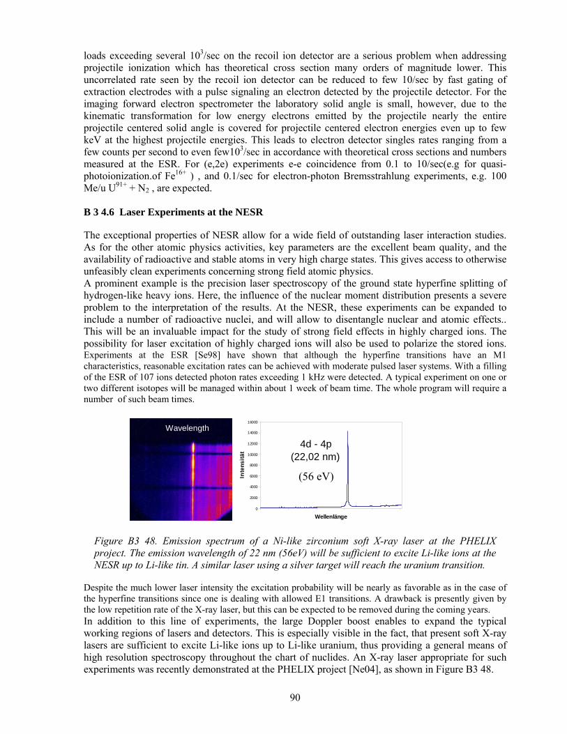
90
loads exceeding several 103/sec on the recoil ion detector are a serious problem when addressing projectile ionization which has theoretical cross section many orders of magnitude lower. This uncorrelated rate seen by the recoil ion detector can be reduced to few 10/sec by fast gating of extraction electrodes with a pulse signaling an electron detected by the projectile detector. For the imaging forward electron spectrometer the laboratory solid angle is small, however, due to the kinematic transformation for low energy electrons emitted by the projectile nearly the entire projectile centered solid angle is covered for projectile centered electron energies even up to few keV at the highest projectile energies. This leads to electron detector singles rates ranging from a few counts per second to even few103/sec in accordance with theoretical cross sections and numbers measured at the ESR. For (e,2e) experiments e-e coincidence from 0.1 to 10/sec(e.g for quasi-photoionization.of Fe16+ ) , and 0.1/sec for electron-photon Bremsstrahlung experiments, e.g. 100 Me/u U91+ + N2 , are expected. B 3 4.6 Laser Experiments at the NESR The exceptional properties of NESR allow for a wide field of outstanding laser interaction studies. As for the other atomic physics activities, key parameters are the excellent beam quality, and the availability of radioactive and stable atoms in very high charge states. This gives access to otherwise unfeasibly clean experiments concerning strong field atomic physics. A prominent example is the precision laser spectroscopy of the ground state hyperfine splitting of hydrogen-like heavy ions. Here, the influence of the nuclear moment distribution presents a severe problem to the interpretation of the results. At the NESR, these experiments can be expanded to include a number of radioactive nuclei, and will allow to disentangle nuclear and atomic effects.. This will be an invaluable impact for the study of strong field effects in highly charged ions. The possibility for laser excitation of highly charged ions will also be used to polarize the stored ions. Experiments at the ESR [Se98] have shown that although the hyperfine transitions have an M1 characteristics, reasonable excitation rates can be achieved with moderate pulsed laser systems. With a filling of the ESR of 107 ions detected photon rates exceeding 1 kHz were detected. A typical experiment on one or two different isotopes will be managed within about 1 week of beam time. The whole program will require a number of such beam times.
Figure B3 48. Emission spectrum of a Ni-like zirconium soft X-ray laser at the PHELIX project. The emission wavelength of 22 nm (56eV) will be sufficient to excite Li-like ions at the NESR up to Li-like tin. A similar laser using a silver target will reach the uranium transition.
Despite the much lower laser intensity the excitation probability will be nearly as favorable as in the case of the hyperfine transitions since one is dealing with allowed E1 transitions. A drawback is presently given by the low repetition rate of the X-ray laser, but this can be expected to be removed during the coming years. In addition to this line of experiments, the large Doppler boost enables to expand the typical working regions of lasers and detectors. This is especially visible in the fact, that present soft X-ray lasers are sufficient to excite Li-like ions up to Li-like uranium, thus providing a general means of high resolution spectroscopy throughout the chart of nuclides. An X-ray laser appropriate for such experiments was recently demonstrated at the PHELIX project [Ne04], as shown in Figure B3 48.
0
2000
4000
6000
8000
10000
12000
14000
16000
Wellenlänge
Inte
nsitä
t
4d - 4p(22,02 nm)
Wavelength
(56 eV)

91
The other example, where the Doppler effect is exploited, is the proposed test of special relativity, which relies immediately on the unique combination of high beam velocity and beam quality. The measurement principle is illustrated in Figure B3 49.
Figure B3 49. Measuring principle: A two-level transition in a fast Li+ ion beam is excited from forward and backward direction by Doppler-tuned laser beams. A photomultiplier (PMT) detects fluorescence.
Previous experiments at the ESR and, more particular, at the TSR have demonstrated the capability to reach very high resolution. An example with 10-8 resolution is given in Fehler! Verweisquelle konnte nicht gefunden werden.. For such a high accuracy experiment several beam times of about 1 week each will be needed.
Figure B3 50. High resolution spectrum obtained at the TSR.
A completely new field will be opened by the interaction of ultra-intense lasers with the highly-charged relativistic ions. Recent theoretical work showed, that both the high charge state and the relativistic effects increase the range of recollision phenomena of laser accelerated bound electrons [Ch93]. An example is the emission of high order harmonics, as shown in Figure B3 51. These experiments will also benefit from the capability of detection single charge changed ions in the storage ring. Also the laser repetition rate and the reaction cross sections are low, this will allow to produce significant data within 5 – 10 hours of experiment per data point.
Figure B3 51 Emission rate of harmonic photons in the direction of propagation of the driving laser pulse as a function of the photon energy for (a) a Ne9+ion moving at γ = 15 in the laboratory frame, and (b) an Ar7+ ion at rest, as obtained within the Coulomb corrected SFA. For each ion, the upper curve shows the results obtained within the dipole approximation and the lower curve the results obtained without making this approximation.

92
B 4 Atomic Physics with Decelerated and Extracted Highly Charged Ions B 4 1 Infrastructure and Experiments The experiments which use decelerated and cooled Highly Charged Ions and Antiprotons with rigidities below 4.5 Tm (Eion < 130 MeV/u and Epbar< 700 MeV) extracted from the NESR will be accommodated in the FLAIR building, which is placed in the neighbourhood of the NESR. This building (Figure B4 1) is designed as a complex which includes the experimental areas requested by the experiments presented in the LoIs submitted by the FLAIR and SPARC collaborations, the hall for the Low-Energy Storage Ring (LSR) an the additional areas needed for the off-line mounting and testing of the setups, control and data acquisition rooms, laser labs, power supplies storage rooms, a small workshop and social rooms. The floor space needed only for the proposed experimental setups, both for pbars and HCI, of about 3200 m2, is divided between: the low-energy antiproton experimental areas (41%) : the halls F4 to F9 the low-energy highly charged ions experimental areas (14%): F1 and F2 the Low-Energy Storage Ring (LSR) (21%): F3 The difference of about 24% of the building area is needed for the beam lines, shielding and access ways. In Table B4 1 the sharing of the experimental area between different experiments, as proposed today, is presented. The preliminary layout of the FLAIR building is presented in the Figure B2 1 The subsequent deceleration of the antiprotons requested by different experiments (especially for trapping) implies a certain relative location of the LSR, USR, HITRAP and the experiments. This puts some constraints on the building layout (minimum width of about 45 m, minimum length of about 75 m). The final layout depends also on the FLAIR location within the general FAIR layout and will be established after more detailed beam transport simulations and in consent with the civil construction planner. The main FLAIR building is planned to be a light construction with a clearance of 10 m. Inside, the different experimental areas will be separated by concrete walls of different thicknesses, as imposed by the radiation safety rules (for details see Section C4). Although, depending on the geometry of the different setups, the clearance of the different experimental areas will differ, it is planned to partly use the second floor, where it is possible, as storage, mounting and/or data acquisition rooms. Additionally, an area of about 700 m2, mainly on the ground floor, is requested for off-line mounting and testing, laser labs, control rooms (see section I4). This area should be close to the FLAIR building or distributed between the experimental areas. F1 to F9 areas will be placed on the ground floor. Due to the trap design (see subsection 4.1.3) part of the experiments using decelerated and stored ions at HITRAP, will be placed on the top of the F2 cave and request an additional area, F10, of about 140 m2 and part in F1.

93
Table B4 1. Experimental areas in the FLAIR building.
Nr. Area name Beam parameters Experiment Area Responsible
1. F1 HCI, Eion < 130 MeV/u from NESR and LSR
Interaction of low-energy HCI with composite and solid targets
A. Bräuning-Demian, GSI
2. F2 HCI, Eion = 4 MeV/u p-bar, E = 4 MeV from NESR and LSR
HITRAP W. Quint, GSI
3. F3 HCI, E < 15 MeV/u p-bar E = 30 MeV/u from NESR
Low-energy Storage Ring (LSR)
H. Danared, MSL, Stockholm
4. F4 p-bar, E < 300 keV from LSR
Ultra-low Energy Storage Ring (USR)
C. Welsch, MPI, Heidelberg, M. Grieser MPI Heidelberg
5. F5 p-bar, E < 20 keV from USR
Antihydrogen-Experiment
J. Walz, Univ. Mainz
6. F6 p-bar, E < 20 keV to rest from USR and HITRAP
Antihydrogen-Experiment
E. Widmann, S. Meyer Inst., Wien
7. F7 p-bar, 300 keV < E < 30 MeV from LSR
Nuclear and particle physics with antiprotons
D. Grzonka, FZ Jülich
8. F8 p-bar, 30 MeV < E < 300 MeV from NESR
P-bar interaction with biological probes
M. Holzscheiter, pbar medical, USA
9. F9 p-bar, E < 20 keV from USR / HITRAP and RIBs from SFRS
Antiprotonic atoms
Y. Yamazaki, Tokyo
10. F10 HCI and pbar, in the keV energy range from HITRAP
HCI experiments and pbar experiments
W. Quint, GSI
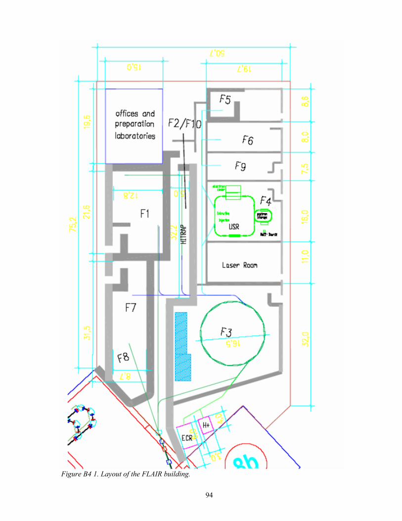
94
Figure B4 1. Layout of the FLAIR building.

95
The low-energy Storage Ring (LSR) CRYRING (Figure B4 2) is an accelerator facility at the Manne Siegbahn Laboratory at Stockholm University. Its main components are a 52-m-circumference synchrotron and storage ring with electron cooling, an RFQ, an EBIS ion source, an ECR ion source and ion-source platform for singly charged ions. CRYRING has been in operation since 1992 for experiments mainly in atomic and molecular physics, but also in accelerator physics and applied physics. In 2002, the Swedish Research Council decided to discontinue the funding of the facility, and it was agreed with Stockholm University in 2003 that funding level should reach zero by the end of 2006. Since the CRYRING synchrotron has an operating energy range from approximately 300 keV (for protons) up to the lowest energies that can be reached with the NESR ring at FAIR, it is equipped with an electron cooler, ultra-high vacuum and it has already been operating with acceleration and deceleration, it has been proposed to move the CRYRING to FAIR and to use it as a dedicated decelerator (Low-energy Storage Ring, LSR) for antiprotons and highly charged ions extracted from the NESR. The LSR/CRYRING installation would, in addition to the synchrotron, include a dedicated low-energy injector for commissioning of the FLAIR facility and its experiments, as well as for training of operators, continuous development of the facility and experiments with ions of other species than those provided from the NESR. We will describe those the most relevant properties of the CRYRING to its proposed new role, the modifications that will have to be made to it and the requirements on the FAIR infrastructure that are needed for a re-installation of CRYRING at FLAIR in section I.
Figure B4 2. Present layout of the CRYRING facility at the Manne Siegbahn Laboratory.
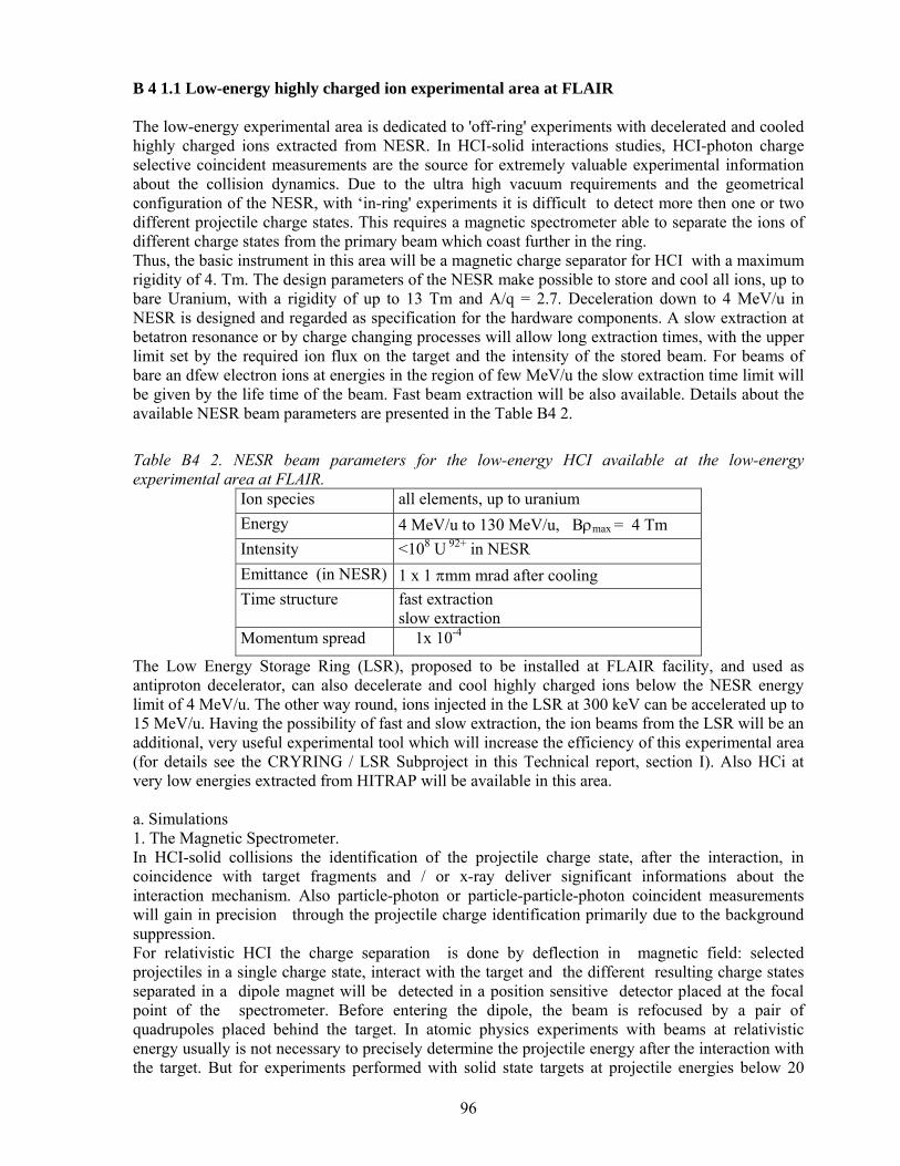
96
B 4 1.1 Low-energy highly charged ion experimental area at FLAIR The low-energy experimental area is dedicated to 'off-ring' experiments with decelerated and cooled highly charged ions extracted from NESR. In HCI-solid interactions studies, HCI-photon charge selective coincident measurements are the source for extremely valuable experimental information about the collision dynamics. Due to the ultra high vacuum requirements and the geometrical configuration of the NESR, with ‘in-ring' experiments it is difficult to detect more then one or two different projectile charge states. This requires a magnetic spectrometer able to separate the ions of different charge states from the primary beam which coast further in the ring. Thus, the basic instrument in this area will be a magnetic charge separator for HCI with a maximum rigidity of 4. Tm. The design parameters of the NESR make possible to store and cool all ions, up to bare Uranium, with a rigidity of up to 13 Tm and A/q = 2.7. Deceleration down to 4 MeV/u in NESR is designed and regarded as specification for the hardware components. A slow extraction at betatron resonance or by charge changing processes will allow long extraction times, with the upper limit set by the required ion flux on the target and the intensity of the stored beam. For beams of bare an dfew electron ions at energies in the region of few MeV/u the slow extraction time limit will be given by the life time of the beam. Fast beam extraction will be also available. Details about the available NESR beam parameters are presented in the Table B4 2.
Table B4 2. NESR beam parameters for the low-energy HCI available at the low-energy experimental area at FLAIR.
Ion species all elements, up to uranium Energy 4 MeV/u to 130 MeV/u, Bρmax = 4 Tm Intensity <108 U 92+ in NESR Emittance (in NESR) 1 x 1 πmm mrad after cooling Time structure fast extraction
slow extraction Momentum spread 1x 10⁻⁴
The Low Energy Storage Ring (LSR), proposed to be installed at FLAIR facility, and used as antiproton decelerator, can also decelerate and cool highly charged ions below the NESR energy limit of 4 MeV/u. The other way round, ions injected in the LSR at 300 keV can be accelerated up to 15 MeV/u. Having the possibility of fast and slow extraction, the ion beams from the LSR will be an additional, very useful experimental tool which will increase the efficiency of this experimental area (for details see the CRYRING / LSR Subproject in this Technical report, section I). Also HCi at very low energies extracted from HITRAP will be available in this area. a. Simulations 1. The Magnetic Spectrometer. In HCI-solid collisions the identification of the projectile charge state, after the interaction, in coincidence with target fragments and / or x-ray deliver significant informations about the interaction mechanism. Also particle-photon or particle-particle-photon coincident measurements will gain in precision through the projectile charge identification primarily due to the background suppression. For relativistic HCI the charge separation is done by deflection in magnetic field: selected projectiles in a single charge state, interact with the target and the different resulting charge states separated in a dipole magnet will be detected in a position sensitive detector placed at the focal point of the spectrometer. Before entering the dipole, the beam is refocused by a pair of quadrupoles placed behind the target. In atomic physics experiments with beams at relativistic energy usually is not necessary to precisely determine the projectile energy after the interaction with the target. But for experiments performed with solid state targets at projectile energies below 20

97
MeV/u, where the energy loss in target is large compared to the incoming energy and, in special cases, without charge state modification (channeling,[Da03]) the energy determination of the outgoing projectile ions is needed. From these considerations the proposed spectrometer must have the following parameters:
- a magnetic rigidity of 4 Tm - a large dispersion for good charge separation: ~ 10 mm for Uranium ions - a momentum resolution of below 5% - the possibility to transport up to 20 different charge states to be imagined at the
focal point by a 2-D position sensitive detector. For the spectrometer design refined calculations of particle tracks in magnetic field are required. These is a task to be performed during the R&D phase of the project. Dedicated simulation programs are already available at GSI (ex. GICO). In parallel, ion-optical simulations for the beam transport through the whole system will be performed using the MIRKO program, special developed at GSI. For the final design the expertise of the group around the GSI Fragment Separator will be used. The final solution must decide about the configuration and the magnet specifications (Milestone). 2. Focal Plane Detector for Heavy Ions The present status and the experience accumulated in the atomic physics group at GSI in HCI detection, point clearly towards a two dimensional position sensitive detector for the spectrometer focal plane. This detector is a very important part of the experimental setup and it should mainly fulfil the following tasks:
- clear separation of projectiles with different charge states and in some cases different energies, too.
- fast timing for coincident measurement. - high sensitivity all over the energy range - beam monitoring: to check the beam profile and to unambiguously determine the beam
intensity. For the intensities available with the slow extracted HCI beams- expected maximum 108 Ions/spill stretched over 50 to 100 s - intensity determination via conventional integration methods (Faraday cup) can not be performed. This must be done using event-by-event counting. The accuracy of this measurement is very important for cross section measurements relaying on charge state separation.
- ion detection in the lower energy range requires a windowless, high vacuum compatible detector.
- in some exceptional cases, for measurements with ions at the high energy end (100 MeV/u and higher ) it is useful to place the detector in air, outside the vacuum chamber.
- simplicity and reliability in use Starting from all these requirements, following design parameters can be derived:
- Two dimensional position read-out with a resolution in both directions around 0.5 mm or better. This position resolution is useful for the compact beams extracted from the storage ring and its final value is strongly coupled to the dispersion of the dipole magnet and the focussing properties of the system. 2D read-out proved to be extremely useful not only for beam monitoring but also for data analysis.
- Fast response: an intrinsic time resolution around 1 ns or better is needed for coincident measurements
- Radiation hardness: for most of the experiments almost the whole beam intensity is seen by the detector. Especially for the heavier ions at lower energy, the energy deposition in material is tremendous (ex. U92+ at 10 MeV/u losses all his energy of 2.38 GeV in 56 µm Diamond, ρ = 3.5 g/cm3) and the induced material defects are considerable.

98
- High counting rate: taking into account the beam intensity design value for Uranium in NESR, a singe-particle count rate capability of up to 106 ions s-1cm-2 is required.
- Efficiency: a 100% detection efficiency over the whole energy range. - Large area: it is extremely useful to be able to simultaneously measure more charge states.
Considering a separation power for the dipole magnet of ~10 mm for U92+ / U91+ and a minimum number of 6 charge states, a minimum area of 80 x 40 mm2 must be considered.
Taking all these into account, neither of the today largely used detectors for relativistic highly charged ions such as semiconductors, gas based detectors and scintillators will properly perform. A completely new choice is offered today by diamond. This insulator is considered as the most important alternative to the use of semiconductors. The operating principle is the same as for semiconductors [Be98]. Its main features are:
- the mean energy needed to produce an electron-ion pair is ~ 13 eV (compared to 2. 96 eV for Ge and 3.62 eV for Si)
- the charge collection length is up to 250 µm for polycrystalline material. - a fast collection time supported by the high break-down field of up to 6 V/µm; this together
with the collection length give an intrinsic time resolution below 100 ps - excellent radiation hardness - versatility for different configurations - affordable price: depending on the quality (layer thickness, polishing, homogeneity) the price
is between 200 Euro/cm2 to 1000 Euro/cm2, even for large area layers. The CVD technology (Chemical Vapour Deposition) used to produce the synthetic diamond allows today the production of good quality diamond layers of 10x10 cm2 at the lowest price. Starting from this material, we propose to build a new generation of position sensitive detectors not only for the use in conjunction with the spectrometer, but even for beam diagnosis as beam profiler and position monitor. Fortunately GSI is a front runner in the Diamond based detector development [Be01]. In the atomic physics group a one-dimensional position sensitive, 60x40 mm2 diamond detector is already available (see Figure B4 3). Used in some experiments [To02],[Ad05] it revealed extremely good performances (fast response, 100% detection efficiency for 70 MeV/u few electron Bi ions, high counting rate). Despite this, the present design has few drawbacks which make it unsuitable as focal plane detector for the future spectrometer, namely the low granularity (1.9 mm pitch) and the fact that is was design to be used mainly for high energy beams extracted in air, i.e. the detector is not vacuum compatible.
Figure B4 3. One Dimensional position sensitive CVD-Diamond detector presently used by the atomic physics group at GSI. Before building a large area detector, a prototype will be designed and built to clarify few points which are not yet decided:
99
- the appropriate structure of the 2-D detector: strips or pads? - the read-out method: single channel or delay line read-out - front-end electronics: the present detector is read out via a special developed broad band,
low-noise charge integrating preamplifier. The signals are then feed into a level discriminator and scalers. The preamplifiers are connected to each individual strip and are stand alone external units. For a detector with 200 to 350 individually read out channels a new preamplifier concept must be developed. The proposed solution foresees to use specially designed integrated electronic chips (e.g. ASICs) mounted directly on the detector or as close as possible to it. This are much smaller compared to the actual preamplifiers and therefore the handling of the detector will simplify. Due to the large difference in the charge amount created in the diamond by ions with the highest and the lowest energy, the new preamplifiers must have variable amplification.
- the read out will tremendously simplify if it will be possible to use the delay line technique. This possibility must be carefully investigated because it is closely connected to the intrinsic diamond properties. This method could tested for low-energy beams which will be stopped into the diamond.
The prototype will be a 20 x 20 mm area detector with a granularity below 1 mm. With this detector the different read-out solutions will be investigated (R&D Milestone). b. Radiation hardness For the kind of experiments proposed to be performed at this setup the radiation hardness is not an important issue for the most of the components. The beam intesnsities available here will be not higher the 106 ions/sec. Only the projectile detector and the beam monitors could be affected by radiation damages. The large amount of energy deposited by highly charged ions at intermediate energies poses serious constraints for the choice of the appropriate detector type. One can think about two scenarios: a cheap detector which can be replaced without high costs after few experiments or to choose a radiation hard material with good detection properties and trade the cost for the radiation hardness. The first choice is the one we have already at GSI. The present focal plane detector is based on an 80 mm diameter MCP chevron stack. Our experience shows that such a detector looses the detection efficiency after 'seeing' approx. 104 U91+ / microchannel at 20 MeV/u. In average, after tree to four experiments the MCPs shows efficiency losses and must be exchanged. The choice of the Diamond – solution has been triggered by considerations connected to the high risk of radiation damages for the focal plane detector. Diamond have proved to be extremely radiation resistive in tests performed width high energy, high intensity beams [Ad00],[Be04a]. However there is an important aspect which needs more investigation: how does the diamond perform under the irradiation with slow, highly charged ions? Most of the information we have today has been obtained with minimum ionizing particles (mip) or high energy HCI (few hundred MeV/u) which deposit a small amount of energy into the material. Heavy ions with energy below 50 MeV/u deposit up to the whole kinetic energy in a material layer thinner then 400 µm. Taking into account the energy needed to create an electron–ion pair in diamond- 13 eV- the energy loss by the HCI will produce a huge space charge which locally will polarize the diamond. It is not yet clear in which extent this phenomenon could affect the signal formation and finally the detector properties. Using the proposed prototype, tests will be performed with beams from the existing GSI facility: most of the tests could be performed at UNILAC, but also SIS-ESR beams will be required. c. Design For the final desin of the experiment-target area, magnet spectronmeter and the projectile detector- detailed simulations are still needed. The final focal plane detector design will be decided after the tests with the proposed prototype will resume (Milestone). These include detector intrinsic properties and tests of the associated read-out

100
electronics. For the design of the preamplifier a close collaboration with the NoRHDia1 research collaboration, created around the GSI diamond detector expert group, is pursued. d. Construction The construction of the magnetic spectrometer will be realised at GSI, after purchasing the magnets. Depending on the final parameter list, the needed magnets could be constructed by our Chinese collaborators from the Institute of Modern Physics in Lanzhou. The reduced dimensions of the focal plane detector for HCI will permit to entirely construct it at GSI using the GSI detector lab infrastructure. Only the segmentation of the Diamond foil must be done in a specialized lab, outside GSI. Due to the fact that more groups are interested in developing diamond detectors for the new generation of experiments at FAIR, we hope to find a way to optimize the costs. The collaboration with the NoRHDia will be extremely helpful in the realisation of the proposed detector. e: Acceptance Tests does not apply f. Calibration refer to D4 g. Request for test beams
Test Beam Year Delay–line readout test for
the diamond detector UNILAC 2005
2-D diamond detector prototype
UNILAC and SIS/ESR highly charge ion Beams
E <11 MeV/u and E= 50 MeV/u
2007-2008
Test of the Beam Monitor detector
HCI beam from ESR, E<20 MeV/u
2009
Test and commissioning of the focal plane detector
LSR/NESR beams of highly charged ions
2011
Commissioning of the spectrometer
LSR beams 2011-2012
1 NoRDHia -Novel Radiation Hard CVD Diamond Detectors for Hadron Physics: Joint Research Activity in the frame of the EU supported Integrated Infrastructure Initiative on Hardon Physicsb (I3HP) (2004 to 2007)

101
B 4 1.2 HITRAP The ion trap facility HITRAP – see also the Conceptual Design Report (CDR) 2001 - will employ deceleration of heavy highly-charged ions and antiprotons from 4 MeV/u down to cryogenic temperatures. The HITRAP facility will be installed and operated at the ESR storage ring at the present GSI facility, and then moved to the future project, where it is an integral part of the FLAIR facility. HITRAP is a GSI-midterm project and is supported within the Helmholtz-Gemeinschaft by 'additional funding'. Technical and financial details are presented in the HITRAP Technical Design Report, see http://www.gsi.de/documents/DOC-2003-Dec-69-2.pdf. Ions up to uranium U92+ at 4 MeV/u will be provided by the NESR through a direct beamline between the NESR and the HITRAP facility. Antiprotons at 4 MeV will be provided to HITRAP by the LSR (see Figure B4 4). The deceleration in the HITRAP facility is performed by a single Interdigital-H (IH) structure operated at 108.408 MHz, which reduces the energy down to 500 keV/u, followed by a Radio-Frequency-Quadrupole (RFQ) structure operated at the same frequency for further deceleration to 6 keV/u. In order to increase the efficiency, two buncher cavities (first harmonic/second harmonic) will be placed before the IH structure, and another one between the IH and the RFQ structure. Existing 200-kW RF-tube amplifiers can supply both decelerator structures. This considerably reduces the costs for the set-up. After the RFQ structure, the ions and antiprotons will be trapped and cooled down to cryogenic temperatures by means of electron and resistive cooling in the HITRAP cooler trap.
Figure B4 4. Outline of HITRAP facility at the curren ESR locationt (longitudinal cut along the beamline). The decelerator and the trap can be equally well used for heavy ions and antiprotons to bring them down to sub-thermal energies as all components have been carefully designed to be operable in a q/A range of > 1/3. From the cooler trap, the particles will be extracted and delivered to heavy-ion and antiproton physics experiments. Extraction is possible both in DC mode and bunched mode at a time-averaged rate of 104 ions/sec and 106 antiprotons/sec. Beam transfer takes place in transfer lines at ultra-high vacuum. Typical extraction voltages will be around 15 kV. Bunchers, IH, RFQ, and cooler trap will be located in the HITRAP cave next to the Low-Energy Cave A. Including sections for drifting after re-bunching and for differential pumping between the RF cavities and the UHV of the ESR on one side and the traps on the other, the total length of the decelerator section before the cooler trap is planned to be not longer than 16 m. The height of the HITRAP cave will be 4 m. The experiments behind the cooler trap will be located i) in the low-energy experimental areas (F5, F6, and F9) and ii) on a platform on top of the HITRAP cave (F10) in the FLAIR building. The necessary supplies and the control rooms for the HITRAP facility will also be put on the platform on the second level.

102
The experience gained at the present GSI facility will allow for a successful operation of HITRAP without too many transition losses. Essential is the compatibility of HITRAP with the future facility in all major components (decelerator, traps, beamlines). After successful operation at the ESR and the final shut-down of this storage ring, the HITRAP components will be dismounted and mounted again at the FLAIR facility. Further work for development will not be required, except adjusting controls, beam diagnostic tools etc. to the then new standard for FAIR, which at present does not yet exist. It is expected that these relatively minor modifications will allow for a successful start of the experimental work almost immediately after start of operation of the NESR and thus contribute to the scientific output of the new facility right from the beginning. B 4 2 Experiments B 4 2.1 Precision Spectroscopy of Slow HCI with the Reaction Microscope The AP Low-energy Cave and the HITRAP facility in the FLAIR building offer unique possibilities to study the collisions between slow highly charged ions (HCI) up to U92+
and atomic/molecular targets: beams of antiprotons and HCI directly extracted form the LSR with energies from few MeV/u down to 300keV/u and down to eV beams from HITRAP, in both cases with the highest charge states for stable ions and a variety of unstable isotopes, are delivered directly into this Low Energy Cave. The study of ionization processes near the threshold for very high Sommerfeld parameters q/v and charge exchange processes in collisions between ions and atoms/molecules makes it possible to probe both atomic structure and collision dynamics over a range of parameters not accessible anywhere else and is of particular interest for plasma physics, astrophysics and accelerator physics. In the collision velocity range available in this Cave A the charge exchange process dominates at low ion energies (< few keV/u) and its cross section increases steeply with the charge of the ion. We intend to perform precision spectroscopy of HCI with the COLTRIMS technique (reaction microscope). For slow HCI impact on atomic/molecular targets single and multiple electron capture occur with high probability. Thus, singly and higher excited states of the HCI are populated, allowing the formation of strongly inverted systems (”hollow atoms”). The momentum of the recoil ion along the projectile beam axis depends on the difference between the binding energies of the active electron in the initial and final state, i.e. on the Q-value and thus spectroscopic information about the energy levels of the HCI can be obtained. The excited states of the HCI can decay radiatively and/or by emission of Auger electrons. These electrons as well as the photons in the optical and X-ray energy range will be detected in coincidence in order to fully understand the decay schemes of the HCI. With a beam intensity of 104 ions/s, we will carry out single-electron capture experiments. In an earlier experiment [Fi02] we have achieved a resolution (FWHM) of 0.7 eV and a precision of 3-300 meV for the excited energy levels of Ne6+ (120-170 eV relative to the ground state), which is already competitive with the methods of conventional spectroscopy. Our main goal is to increase the momentum resolution by a factor of 10 and to determine the excitation levels of the HCI with sub-meV precision. In the future, provided a beam intensity of 105 ions /s and even 106 ions /s becomes available, we intend to study in detail the rearrangement processes of HCI. For this purpose, a special multi-hit detector for detection of many electrons in coincidence (up to 10 electrons) with extreme time resolution will be developed. In addition, photon detectors for the optical and X-ray regime will be implemented. This will allow for the complete investigation of the decay channels of strongly inverted systems (”hollow atoms”) by detection of photons in addition to the momenta of emerging ions and electrons. The present setup allows us to carry out kinematically complete collision experiments with increased momentum resolution. It consists of a reaction microscope [Ul03] and a projectile analyser [Fi02] (Figure B4 5). The latter permits to detect the charge state of the projectile ion after the collision with the atomic/molecular target in the reaction microscope. The whole setup has been

103
designed, simulated, constructed and tested at the Max-Planck-Institut in Heidelberg. Our group has 10 years of extensive experience in designing, building and operating reaction microscopes.
Figure B4 5. Proposed set-up for precision spectroscopy of HCI with a reaction microscope at the HITRAP facility/Low-Energy Cave. In 2004, our setup has been successfully tested by performing precision spectroscopy experiments with HCI extracted from the Heidelberg Electron Beam Ion Trap (EBIT). HCI (F7+, Ne10+, Ar16+ and U64+) have been extracted from the EBIT at energies of 10-14 keV/q (q is the projectile charge) and have crossed the supersonic gas jet of He in the reaction microscope. Typical projectile beam intensities were 105 ions /s and 104 ions /s, for the light HCI and the U64+ ions, respectively, after focussing and collimating on a 1 mm2 spot in the reaction volume. For the given target density and estimated electron capture cross sections, these intensities permit to carry out capture experiments with satisfactory statistics within a few days. The analysis is still underway. Double and multiple electron capture events are present in the data, as well. This setup or a similar one is ready to be installed at the HITRAP facility/Low-energy CaveA once our beam requirements (see below) are fulfilled.
Simulations, Design, Construction The whole setup is already operational. There is no need for further simulations, design and construction.
Radiation Hardness (of detectors, of electronics, of electrical components nearby) Radiation hardness is not an issue at the ion beam intensities required for our experiment.
Acceptance Tests Since the ion beam provided at HITRAP and at the Low-energy Cave has a small emittance, the acceptance of our reaction microscope is not a limiting factor for the overall setup.
Calibration (if needed) No calibration needed.

104
requests for test beams The setup has been tested in Heidelberg with HCI from the EBIT. No test beams are needed at GSI before the final installation in the cave. B 4 2.2 Ion-Surface Interaction Experiments at HITRAP/Low-energy Cave A a. Experimental scope We want to build up an experimental set-up to be operated for ion-surface experiments using H-, He-, and Li-like highly charged ions (HCIs). We will investigate the filling processes by electron- and X-ray-spectral features stemming from Hollow Atoms, and furthermore the surface response on the provided ultra-high electric fields. On insulating surfaces we expect to observe signatures from the Trampoline effect meaning that the neutralization process can not be completely finished due to a lack of electrons provided within a sufficient short response time by the surface. In addition, we intend to apply time-of-flight secondary ion/neutral mass spectrometry (HCI-SIMS/SNMS) for studying irradiation effects in various materials including fragmentation and modification of biological systems and HCI-induced surface reactions. Applications of SIMS and SNMS techniques with HCI are strongly supported by recent findings of high particle emission yields from oxidized silicon surfaces due to slow HCIs impact. Next to solid insulator and metal targets we will investigate magnetic properties of thin-films, and beam focussing characteristics of insulating and semi-conducting nano-capillaries. Lately, insulating nano-capillaries have shown strong guiding and bending effects when HCI are passing through. Such nano-capillaries will allow fabrication of ion lenses for nanometer size focus working without electromagnetic elements. They also can be used as filters for macro-molecules, and for selective bio-organism capture by exploiting their electric properties. With extremely highly-charged ions interesting non-linear effects in the charge-up process of the capillary surfaces are possible. To reach the proposed goals we develop new electron detection systems allowing us to perform energy, charge state, and yield measurements with large angle acceptance. Furthermore, time-of-flight (TOF) spectrometers for mass identification of scattered and sputtered ionic and - by including a post-acceleration stage - neutral particles will be constructed (Figure B4 6). The design of all detectors takes special care of highest detection efficiencies. We gratefully acknowledge the support in detector development by the group of V. Mikoushkin, St. Petersburg and the collaboration with W.M. Arnold Bik (Utrecht) in target preparation. b. Simulations
Figure B4 6. Schematic view of a typical experimental plane for ion-surface experiments.

105
Simulations to study detector properties as well as the physics behind the measured spectra are required. Simulations for the detectors have been partly performed with the support by V. Mikoushkins group from St. Petersburg. Concerning the electron yield measurements as well as the charge and trajectory distributions in order to measure the Trampoline effect simulations will be provided by the group of J. Burgdörfer from Vienna. Simulations of the ion beam will be performed by the Vienna and the KVI group using e.g. the program code SIMION. These simulations can only be performed after all details concerning distances and ion steering components of the beam line are known. c. Radiation hardness
Since all experiments will be performed using exclusively low intensity ion beams of low energy, i.e. smaller than 20keV/u, radiation damage is not an issue. d. Design
To soften the requirement of beam intensity, a new type of electron spectrometer with a high acceptance angle is being designed in collaboration with V. Mikoushkin from St. Petersburg. The work on the yield detector is done together with the group of J. Burgdörfer from Vienna who will also perform the required ion beam simulations. The design of the complete experiment will be done in close collaboration with the groups of A. Warczak and R. Pedrys from the IP JU Krakow, and R. Schuch from Stockholm. The Krakow group also takes responsibility for the TOF-SIMS mass spectrometer and will deliver an X-ray spectrometer (see a project described elsewhere). A close collaboration on the field of detector development and surface science has been already established between all these groups. Our low energy electron measurements require an excellent shielding of outer magnetic fields. This will be ensured by adding a µ–shielding in the recipient. Nevertheless high magnetic fields in the vicinity of the set-up have to be avoided during testing and operation phase.
e. Construction
The construction of all necessary parts will be shared among the participating groups; therefore frequent contacts/meetings of the members will be organized. For the design and construction of the UHV system including recipient, target transfer, pumping stage, and target preparation facilities the KVI group takes responsibility. The required detector systems will be constructed, tested and mounted to the set-up in collaboration with the groups mentioned under point (d). f. Acceptance Tests
The ion-surface experiment is the end-user of the ion beam, so the acceptance will not limit any other experiment. We will estimate the acceptance of our experiment within the ion beam simulations (see point (b)). g. Calibration
Calibration might be needed for the newly designed detectors. It is planned to perform these calibration measurements partly at set-ups in Krakow, Stockholm, and Groningen before mounting the systems at the HITRAP facility/Low-energy Cave A. Here different kinds of ion sources (single charge, ECR, Molecules, etc.) will be utilized.
h. Request for Test Beams
For testing the system, aligning the target, taking into work the new detectors, etc. we require several test beams, preferably with multiply-charged ions served by an ECR or EBIS source. The test beams should be of low and high intensity and of variable total energy (ranging from below 1 keV to ≈100 keV). For calibrating the TOF system different molecular beams (variable m, q) are required.

106
B 4 2.3 X-ray Measurements at HITRAP/Low-energy Cave A For X-rays studies HITRAP will porovide about 105 few-electron or even bare high-Z ions up to uranium, with a repetition rate close to 10 s. Therefore, even transitions in H- or He-like high-Z ions in the X-ray regime between 2 keV and 30 keV can be studied by means of high-precision crystal spectrometers with efficiencies of about ε ≈ 10-6. Because for X-ray experiments at HITRAP the ions are basically at rest, such experiments would also profit considerably from the use of X-ray optics such as discussed for the NESR experiments. This would result in substantially increased soild angle (at least an order of magnitude) .Even more promising would be the use of state of the art high-resolution calorimeter systems in combination with X-ray optics where an overall efficiency of close to 10-3 appears to be achievable [Eg96],[Si03] (see Photon Spectroscopy in section B3). We propose to place the experimental target chamber in the position shown in Figure B4 4. This target chamber should be equipped with an open, well collimated, differentially pumped gas target. It is expected to have an areal target density of about 1011 atoms/cm2. The beam line should be equipped with an electrostatic charge state analyzer which is crucial for the experiment. Beams of highly charged ions should be extracted from the cooler trap and delivered to the collisions chamber with energies in the range of 0.1 – 20 keV/q and with intensities of 105 particles every 10 sec. It is assumed to have an ion beam with a diameter of 3-5 mm at the target. With a vacuum in the range of 10-10 to 10-11 mbar in the beam line and at the maximal distance between the cooler trap and the target chamber of about 10 m, a sufficient charge-state purity of the beam is guaranteed. According to [Ja85], a single-electron-capture cross section of about 10-12 cm2 is expected for capture into highly charged uranium from multi-electron target atoms. The aim of this work is to build, test and bring into operation elements of the collision chamber (differentially pumped gas target, electrostatic charge state analyzer, collimators, slits, movable X-ray detector holders). In addition, development of special solid-state detectors is foreseen. This particular contribution is described separately in part 2.8 – Photon detector development. Simulations Simulations of the beam trajectories in the target area as well as in the electrostatic charge state analyzer are crucial for precise, efficient and background free X-ray detection. Mainly single particle trajectory tracking codes will be used, as e.g. SIMION. This program is based on a Runge-Kutta (4th order) iteration technique to calculate magnetic and electrostatic fields from a given electrode geometry by solving the Poisson equation. Design The design of elements mentioned above will be made in close collaboration with GSI, Stockholm and KVI groups. They have extensive experience in designing such components of the setup. It is expected, that the design requires about two man-years.
Construction The construction of the elements is planned to be performed at the workshop of the Physics Institute of the University in Cracow as well as at the workshop of the PREVAC Company, one of the leading workshops of this profile in Poland.
Tests and calibration Here, tests of the differentially pumped gas cell are required under stringent vacuum conditions. Calibration of target densities for different gases is also planned.

107
B 4 2.4 g-Factor Measurements It is intended to develop and operate a cryogenic Penning trap setup for high-precision measurements of magnetic moments (g-factors). The measurement principle can be used both for the determination of electronic g-factors in single highly-charged ions and of the free protonic and antiprotonic g-factor. The aimed experimental uncertainty is a few parts in 10-9. Similar high-precision measurements of electronic g-factors in hydrogen-like ions have been performed before, however only on light, hydrogen-like ions. Nevertheless, already with these ions it was possible to obtain interesting results. Apart from tests of quantum electrodynamics in the presence of strong fields, fundamental constants like the electron mass or the fine-structure constant and also nuclear parameters can be determined with outstanding accuracy [Be02]. Recently, measurements on 12C5+ [He00],[Ha00] and 16O7+ [Ve04] have been used to determine the electron mass four times more precise than before [Be02a],[Ye02]. The present kind of g-factor measurement is based on the “continuous Stern-Gerlach effect” [We02] and relies on high-precision measurements of trapping frequencies of single, hydrogen-like ions stored in a Penning trap [Br86]. Since the g-factor of an electron bound in a hydrogen-like ion is subject to various effects in reach of theoretical calculations [Pe96], it is possible to benchmark these with high sensitivity. Most prominently, these are bound-state QED, nuclear volume and nuclear recoil effects. In particular, the suggested experiment will yield as benefits:
• A comparison of measured g-factors with theoretical predictions will test the corresponding bound-state QED calculations. Since the stringency of such a test scales roughly with the nuclear charge Z squared it is of interest to perform measurements also on medium-heavy such as 40Ca19+ [Vo] and heavy ions such as 238U91+ [Pe96], [Vo].
• Assuming the validity of the QED calculations, the comparison of theory and experiment leads to the determination of fundamental constants such as the electron mass or the fine-structure constant α as the most imprecise values when comparing experiment and theory. This has been partly demonstrated already [Be02a], [Ye02] and further improvements are at hand.
• Measurement of the Zeeman splitting on odd isotopes of hydrogen-like ions leads to nuclear magnetic moments without any correction by diamagnetic shielding. For the first time, this would provide a test of calculation of shielding constants for neutral or singly ionised atoms which up to now serve as the only source for nuclear magnetic moments. This led to several mistakes in the past, as discussed in [Gu98]. A possible difference of the nuclear magnetic moments between hydrogen-like ions and systems having many electrons may lead to the observation of the influence of the electron cloud on the nuclear wave functions.
• Comparisons of electronic g-factors in hydrogen-like and lithium-like ions allow for the separation of nuclear structure effects. At the same time electron correlation effects in Li-like systems can be observed [Sh02].
• Comparison of cyclotron frequencies of single ions in the same magnetic field of the Penning trap leads to mass comparisons of heavy highly charged ions at the 10-10 level of precision. This was already demonstrated for carbon and oxygen [He00], [Ha00], [Ve04]. It also serves for the determination of electron binding energies in a series of charge states starting from hydrogen-like to singly ionised systems. This tests ab-initio calculations of atomic structure.
In the planned setup, a single ion will be stored in a cryogenic Penning Trap, which is located in the homogeneous part of the magnetic field produced by a superconducting NMR-magnet.

108
77K shield
lq. Nitrogen
lq. Helium, 4K
magnet coil
trap chamber
vacuum
2,5
m
cryogenic detectionelectronics
Helium Inlet/Ouletroom temperatureelectronics
beam line / injection
beam control
Penning traparrangement
Figure B4 7. Schematic drawing of the experimental setup. A magnetic field strength of around 4T inside the trap (Figure B4 7) will ensure the radial confinement of the ion, while the axial trapping is performed in an electric potential minimum of several eV⋅ q. The ion motion under this condition is a superposition of three individual trapping frequencies which can be measured independently in a non-destructive way and with high precision by resonant detection in electronic resonance circuits with high quality factors. Experimentally, the g-factor is obtained from the relation
eq
Mmg
C
L
ωω2= ,
where ωL is the Larmor precession frequency of the electron spin around the magnetic field, ωC is the cyclotron frequency of the ion, m is the electron’s mass, M is the mass of the ion, and q is the ion’s electric charge. The frequency ratio ωL/ωC is determined by irradiation of microwaves of a frequency ωMW and a scan of the spin flip probability as a function of ωMW/ωC. The ratio with the maximum spin flip probability, ωL/ωC, yields the g-factor. Spin-flip detection is performed by transport of the ion to one of the traps in which the magnetic field homogeneity is influenced by using ferromagnetic elements. In such an inhomogeneous field, the trapping frequencies depend on the spin orientation. By using the “continuous Stern-Gerlach effect” [He00] the spin direction can be determined. The ion is transported back and the next microwave frequency is applied, thus scanning the Larmor resonance. It can be assumed that the relative precision reached in measurements on hydrogen-like carbon and oxygen, 12C5+: g=2.001 041 596 3 (10)(44) [He00], [Ha00] and 16O7+: g=2.000 047 026 8 (15)(44) [Ve04], can be reproduced for all ions up to 238U91+. The larger uncertainty for both given numbers is caused by the tabulated mass of the electron and the smaller indicates the experimental precision. Improvements in this experimental precision of up to a factor of five and a reduced measurement

109
time of roughly one order of magnitude seem possible from the recent experiences in the field [Vo],[Ve04a],[St].
1 Operation at HITRAP The scenario for the experiments at HITRAP looks as follows: A bunch of hydrogen-like ions is ejected from the experimental storage ring ESR, decelerated to several keV/u and finally cooled in the Cooler trap of the HITRAP facility. After this procedure, they are extracted from the Cooler trap, transported in a cryogenic beam line and injected into the present Penning trap setup. After capturing the ions, the trap will be separated from the external source by a cryogenic valve to maintain a cryogenic vacuum below 10-14 mbar in the trapping region. This is required to avoid ion loss by electron capture in collisions with background gas. A single ion is prepared by adiabatic lowering of the trapping potential and subsequent selective excitation of the few remaining ions. This ion will be cooled to the ambience temperature in all degrees of freedom by the technique of resistive cooling, using superconducting resonance circuits tuned to the ion oscillation frequencies. In order to perform a g-factor measurement, the “continuous Stern-Gerlach effect” can be applied and microwaves can be used to obtain a Larmor resonance as described above. A simultaneous measurement of the cyclotron and spin resonance frequencies yields the value for the g-factor. High precision at the 10-10 level can be obtained by separating the determination of the spin direction from the measurement region with a homogeneous field by adiabatic transport of the ion between these two positions in a special double-trap structure [Ha00]. It has to be stressed that up to now, only the planned HITRAP facility can provide heavy highly charged ions sufficiently cold to be injected into the present Penning trap setup.
Simulations The ion motion in the trap system and technical requirements for ion injection will be studied in simulations. It is especially necessary to study the ion motion inside the high-precision Penning trap and the ion injection into the Penning trap system with respect to in-flight-capture of externally produced ions. Mainly single particle trajectory tracking codes will be used, as e.g. SIMION. This program is based on a Runge-Kutta (4th order) iteration technique to calculate magnetic and electrostatic fields from a given electrode geometry by solving the Poisson equation. Radiation Hardness Since the high-precision g-factor measurements are performed with a single trapped ion, radiation hardness is not an issue.
Design The Design will be made by the Mainz group in close collaboration with GSI. There exists extensive experience in designing trap setups. It is expected that the design will take about two man-years.
Construction The basic construction ideas have been described above. It is a very complex setup both with respect to mechanical precision and to measurement and detection electronics. Similar cryogenic traps are already under operation at several places (e.g. at Mainz). The Mainz workshop is one of the leading places for the construction of precision Penning traps and its expertise will be used.
Acceptance Tests The acceptance of the Penning trap system is not thought to limit the program of the proposed setup since the ion beam provided by the HITRAP cooler trap has a small beam emittance.
Calibration (if needed)

110
The only calibration needed is that of the magnetic field strength of the superconducting magnet. After installation this will be done first by use of a standard NMR probe. Later, the calibration will be performed by determination of the cyclotron frequency of ions with well-known masses.
Requests for test beams In the cases where externally produced ions are to be investigated in the Penning trap system, an external ion source may be used for tests of the ion guidance system. Test beams are not necessarily required. B 4 2.5 Mass Measurements Penning trap system for high-precision mass measurements on highly-charged ions (with its necessary R&D, Prototyping, Tests, Milestones to reach specifications for each subproject) The aim of this work is to build and operate a cryogenic Penning trap mass spectrometer for mass measurements on fundamental particles, as e.g. electron/positron, proton/antiproton, and highly charged ions with a relative uncertainty of 1·10-12. This precision would allow to perform a stringent test of CPT symmetry by mass ratio measurements of particles/antiparticles and test of QED in highly-charged ions. Furthermore a precision of 1⋅10-12 would allow one to measure the binding energy of highly charged uranium, with one or a few electrons, better than presently achieved by X-ray spectroscopy. In order to avoid uncertainties due to fluctuations of the electromagnetic fields, ion-ion interactions, and large field inhomogeneities, we plan to build a four-trap system, with two preparation and two high-precision Penning traps (Figure B4 8). All four miniaturized hyperbolical traps have to be installed in the same superconducting magnet with highest field stability and homogeneity and with a field strength of at least 7 T. Non-destructive phase-sensitive cyclotron frequency measurements will be performed simultaneously by storing the two resistively cooled ions in different traps but within the same homogeneous region of the magnet. After such a measurement, the position of the ions will be exchanged by using the two preparation traps (or a new reloading of the traps from the preparation traps) and the measurement of the cyclotron frequency will be repeated. In this way ion-ion interactions are avoided and one can expect that magnetic-field changes as well as systematic errors will cancel to a large extent in the measured frequency ratios. At a later stage the ion of interest and the reference ion or both ions of interest will be cooled to below mK temperatures by exchange of energy with an ion (preferably 24Mg+) which has been laser cooled to the zero-point state. The laser cooling of 24Mg+ will take place in the preparation traps since no extreme field homogeneity is needed.
He - CRYOSTAT WITH SUPERCONDUCTING INDUCTIVITY
LHe-RESERVOIR
4 K
300 K
4 K
7 T - MAGNET - WITH FOURHOMOGENEOUS CENTERS
VACUUMSYSTEM
DETECTOR
2 PRECISION2 PREPARATION
TRAPSBENDER
ION SOURCE DETECTOR
FEEDTHROUGHS
Figure B4 8. Proposed high-precision mass spectrometer setup at the HITRAP facility. The trap system is installed in a 7 T superconducting magnet. Depending on the stored particle (light particle or highly charged heavy ions) either a destructive time-of-flight cyclotron resonance or a non-destructive Fourier transform ion cyclotron resonance detection will be used.

111
Simulations Simulations are especially necessary to study the excitation of the ion motion inside the hyperbolic high-precision Penning trap. Detailed simulation studies of the ion motion have already been performed at ISOLTRAP, a Penning trap mass spectrometer for short-lived radionuclides at ISOLDE/CERN.
of the detectors Destructive (time-of-flight ion cyclotron resonance, TOF-ICR) as well as non-destructive detection techniques (Fourier-transform ion cyclotron resonance, FT-ICR) will be used to measure the cyclotron frequency of the stored ions. Both techniques are well known and novel detectors are presently under construction at the Institute of Physics at the University of Mainz. Detailed simulations are not needed.
of the beam Beam simulation is mandatory to reach the envisaged accuracy. Mainly single particle trajectory tracking codes will be used, as e.g. SIMION. This program is based on a Runge-Kutta (4th order) iteration technique to calculate magnetic and electrostatic fields from a given electrode geometry by solving the Poisson equation.
Radiation Hardness (of detectors, of electronics, of electrical components nearby)
Since the high-precision mass measurements are performed preferably with a single trapped ion, radiation hardness is not an issue.
Design, The Design will be made in close collaboration with the MSU, GSI, and Mainz groups. They have extensive experience in designing trap and detector setups. It is expected, that the design including calculations of the field inhomogeneities will take about two man-years.
Construction The construction ideas are described in the introduction of this section. It is a very complex setup and a four-trap system has never been built before. Detailed calculations of the magnetic field distribution are therefore required. Cryogenic traps are already under operation at several places (CERN, MSU, and Mainz). The Mainz workshop is one of the leading places for the construction of hyperbolical precision Penning traps and its expertise will be used.
Acceptance Tests A standard acceptance test will be required of the magnet manufacturer. After installation of the trap system, off line tests will assure that the required performance is reached. Since the traps are being built within the FLAIR/HITRAP collaboration, no formal acceptance tests as such are specified. Calibration (if needed) The only calibration needed is the calibration of the magnetic field strength of the trap magnet. This will be done first using a standard NMR probe by the manufacturer. Later the calibration will be performed by the determination of the cyclotron frequency of stable ions with well-known masses. To this end, an off-line reference ion source will be installed which provides preferably also highly-charged ions. Here, carbon or carbon cluster ions provide the reference mass of choice [Bl02a] since the unified atomic mass unit is defined as 1/12 of the mass of 12C. Mass measurements on well-known masses allow the study of the accuracy limit of the proposed setup [Ke03]. Requests for test beams In order to get the precision mass spectrometer operational, there is no external test beam needed. Stable (highly-charged) ions provided by the test ion source will be used to make the necessary tests.

112
B 4 2.6 Laser Experiments
Figure B4 9. Schematic drawing of the setup. The UHV chamber contains a split-coil superconducting magnet, which surrounds the spectroscopy Penning trap (Figure B4 10). The superconducting magnet has a high homogeneous and stable magnetic field on axis (B=6 T) over the entire trap length. The chamber is evacuated by an ion pump (after roughing). The laser beam coming from the left prepares the HCI in the upper hyperfine state. The fluorescence is detected perpendicular to the beam and transported out of the chamber (by fibres) for further signal analysis, processing and acquisition. a) Experimental scope The HITRAP facility offers an exciting new possibility for high-precision measurements of the ground state hyperfine structure of hydrogen-like systems. The results can be used for the investigation of the nuclear effects or, if these effects can be eliminated or calculated, to measure QED effects in extreme fields. In highly-charged ions (HCI), electronic transitions are generally in the far UV or X-ray regions of the spectrum. However when Z is high enough (around Z=70) the ground-state hyperfine transition of hydrogen-like systems (which in hydrogen itself has a wavelength of 21 cm) can move into the visible. Laser spectroscopy offers the possibility of high-accuracy measurements of transition wavelengths in the visible region. The lifetime of the transition falls as Z -9 so that it is of the order of ms in the visible. A measurement of this transition wavelength gives information on the QED corrections to the hyperfine energy or on the distribution of nuclear magnetisation (Bohr-Weisskopf effect) if the QED corrections are assumed to be correct. The distribution of the nuclear magnetisation is affected by core polarisation and it is a property of the nucleus that is not well understood; its measurement allows critical tests of nuclear models to be performed. In addition, comparison of measurements made on other states of HCI allows the nuclear effects to be eliminated so that an accurate measurement of the QED effects may also be made. There are several candidate systems that could be studied at HITRAP. Some of these have already been studied in storage rings, but the potential accuracy of a Penning trap measurement is high because of the elimination of the very large Doppler shift due to the high velocity of the ions in the storage ring. At GSI, measurements were made in the ESR storage ring on 209Bi82+ (λ = 244 nm, τ = 0.35 ms) and on 207Pb81+ (λ = 1020 nm, τ = 50 ms); measurements were also made at the Super-EBIT on 165Ho66+, 185Re74+ and 187Re74+ and 205Tl80+. Compared to the storage ring and EBIT measurements, HITRAP offers several distinct advantages:
• No calibration of the beam velocity is required • The ions are held at low temperature and high density

113
• The resonance is expected to be much narrower, leading to higher precision • The experiment will be performed in a clean environment with essentially no background
light • The trap will be designed to have efficient light collection, giving high sensitivity • A possible extension is to use a laser to optically pump the ions, leading to polarisation of the
nuclear spin and the possibility of weak interaction studies.
Figure B4 10. Schematic drawing of the spectroscopy Penning trap. This trap will be utilized with resistive cooling (to assure an ion temperature of ~4 K) and the rotating wall technique (to assure a high density, small ion cloud). Below the trap a possible loading procedure is indicated: the HCI enter the trap from the right, are reflected from the left capture electrode, enclosed by the right electrode, localised to the trap centre (quadrupole potential) and finally cooled and compressed. After laser excitation (on axis) the fluorescence from the upper hyperfine state is detected perpendicular to the laser beam. b) Simulations When designed, we will use SIMION to simulate ion transport from the cooler trap to the spectroscopy trap and use other programs (under development) to verify the rotating wall efficiency. So far, we have already made calculations of the trap frequencies, estimated the effect of the rotating wall technique, and calculated expected signal rates. For example: In hydrogen-like 207Pb81+ the hyperfine splitting of the 1s ground state corresponds to a wavelength of 1020 nm, and the upper state lifetime is 50 ms. At 4 K, i.e. in a cryogenic trap, the Doppler width of the upper hyperfine state (F=1) is only 30MHz. The ion cloud (about 105 ions) in the Penning trap can be radially compressed using the rotating wall technique. Typical cloud dimensions are: a cloud length of ~7 mm and a diameter of ~0.8 mm. lf the total detection efficiency is about 4.10-3, and the experiment is run in a continuous mode, the signal on resonance is expected to be 4.103 counts per second. The background signal is expected to be less than 102 counts per second. Alternatively, if the laser excitation is pulsed with a duty cycle of say 200 ms, the signal would be around 103 counts per second, without any background from scattered laser light. These values are high enough to allow easy detection and measurement of the transition wavelength. Once the signal is seen, this will allow a wavelength determination to an accuracy which far exceeds the theoretical uncertainties.

114
c) Radiation hardness Since all experiments will be performed using exclusively low intensity ion beams of low energy, i.e. smaller than 1 keV/u, radiation damage is not an issue. d) Design The design of elements mentioned above will be done in London, at Imperial College. For the design of the resistive cooling we will work in collaboration the Mainz group, since they have extensive experience in designing such components of the setup. It is expected, that the design requires about two man-years. e) Construction The superconducting magnet (cryogen-free) can hopefully be purchased early in the project. The construction of the laser setup (including the necessary optics), the Penning trap (with resistive cooling) and the fluoresence detection will take place at Imperial College in London, with close consultation with Mainz and GSI. We will mainly use the workshop facilities available at Imperial. f) Acceptance tests Tests of the trap, cryogenic electronics and the detector will be done at Imperial, using singly charged ions. We will study systems with equivalent (hyper)fine transitions and similar characteristics (wavelength and lifetime) and ion cloud parameters. Tests of extraction of the highly charged ions from the cooler trap, and transfer (beamline section) and capture into the spectroscopy trap can only be done at GSI. These tests should not take too long, provided the parameters of the beam extracted from the cooler trap are realistic. g) Calibration The calibration is fairly straightforward. We will only need to determine/calibrate the magnetic field (Hall probe) and the wavelength (wavemeter) of the laser. h) Request for test beams Beams of highly charged ions with medium Z, e.g. 40Ca16+. This will be used for optimising the capture of ions from a beam and the implementation of the rotating wall technique for increasing the density of ions in the trap. 40Ca16+ is an example of an ion with a very similar charge to mass ratio as 207Pb81+. A mass measurement program is also proposed at the low-energy branch within the NUSTAR project (MATS: Measurements with an advanced trapping system). The main goal of MATS is to perform high-precision mass measurements and trap-assisted spectroscopy measurements on very short-lived nuclides which are not accessible at HITRAP. B 4 3 Trigger, DACQ, Controls, An-line/Off-line Computing Low-energy Cave/HITRAP The control of the experiments performed at the Low-energy Cave and HITRAP will be done locally, in the data acquisition rooms of the experimental areas. A correlation with the accelerator is needed: a machine signal is desired for coincident measurements. The HITRAP facility needs trigger signals from the extraction kickers of the storage rings NESR and LSR for exact timing of the HITRAP decelerator and the cooler trap. The beam transport to the experiment, inside the FLAIR building, must be included into the accelerator control and made accesible for the experimenters in the data aquisition room. Beam diagnosis elements, slits, vacuum systems situated inside the caves must be under the control of the experimenters but also connected to the general FAIR (NESR) and LSR control. Especially for

115
experiments using ions from the LSR injectors, the control over the beam must be local accessible from the FLAIR building. Multiparameter data acquisition software is needed: the GSI support for a general platform is welcomed and considered necessary especially for small experiments. B 4 4 Beam/Target Requirements Low-Energy Cave/ HITRAP B 4 4.1 Beam specifications
• highly charged (bare and few electrons) ion beams, up to uranium • decelerated and cooled in NESR, slow and fast extracted to the experimental areas into the
FLAIR building • emittance: 1 x 1 π mm mrad • energies of 130 MeV/u and lower • for few-electron heavy ions, Eion> 4 MeV/u . For beams from the ion injector of the LSR (N,
Ar, Kr, etc.) energies Eion < 15 MeV/u • for channeling experiments: halo free, parallel beams; especially for experiments with low
energy beams; an angular divergence much smaller than the critical channeling angles (typically 0.3 mrad) rms values in x and y is requested
• a beam stability in position at the level of at least 1 mm: this implies a stability of the magnet power supplies at the level of 10-4
• the maximum beam intensity is given by the NESR and LSR parameters and is expected to be up to 107 ion / spill for decelerated bare uranium in NESR at 20 MeV/u. The intensity of the extracted beams depends, among other parameters, on the extraction energy, ion species and extraction time.
• beam spot on target: § 2 x 2 mm2 • spill lengths: 50 to 200 s • commissioning with beam from the ion injectors of the LSR at 4 MeV/u, ion species:
protons, H- ions, light highly charged ions, e.g. Ar16+ • antiprotons at 30 MeV from NESR to LSR and at 4 MeV from LSR • decelerated and cooled in NESR and LSR, fast extraction to the HITRAP area in the FLAIR
building, bunch length ≤ 1 µs • emittance: 1x 1 π mm mrad • the maximum ion beam intensity delivered to HITRAP is given by the parameters of NESR
or LSR (see corresponding sections) and is expected to be up to 107 U92+ ions every 50 s at 4 MeV/u
• the maximum antiproton beam intensity delivered to HITRAP is given by the antiproton production yield at the production target and is expected to be up to 5×10⁸ antiprotons every 50 s at 4 MeV/u
• beam spot on target: 2 x 2 mm2 B 4 4.2 Running scenario 1. Scenario for one experiment: pulse by pulse, at a time interval given by the cooling and deceleration time in NESR. Blocks of 15 to 25 shifts beam on target. Additional 3 to 5 shifts should be foreseen for the settings of the extraction and the transport beam line. At the beginning of the operation it is advisable to plan one or two beamtimes, after the commissioning of the beam line of the Low-energy cave and HITRAP, only with the purpose of exercising the beam transport to the caves. The present experience gained at the ESR in GSI showed that at the beginning the transport setting takes longer and on the long run such a scenario will shorten the time needed for this operation during the physics experiments.
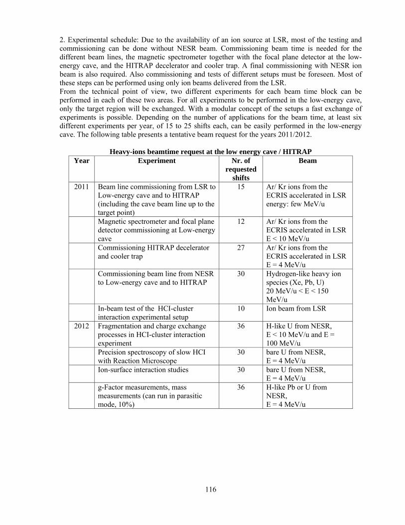
116
2. Experimental schedule: Due to the availability of an ion source at LSR, most of the testing and commissioning can be done without NESR beam. Commissioning beam time is needed for the different beam lines, the magnetic spectrometer together with the focal plane detector at the low-energy cave, and the HITRAP decelerator and cooler trap. A final commissioning with NESR ion beam is also required. Also commissioning and tests of different setups must be foreseen. Most of these steps can be performed using only ion beams delivered from the LSR. From the technical point of view, two different experiments for each beam time block can be performed in each of these two areas. For all experiments to be performed in the low-energy cave, only the target region will be exchanged. With a modular concept of the setups a fast exchange of experiments is possible. Depending on the number of applications for the beam time, at least six different experiments per year, of 15 to 25 shifts each, can be easily performed in the low-energy cave. The following table presents a tentative beam request for the years 2011/2012.
Heavy-ions beamtime request at the low energy cave / HITRAP Year Experiment Nr. of
requested shifts
Beam
2011 Beam line commissioning from LSR to Low-energy cave and to HITRAP (including the cave beam line up to the target point)
15 Ar/ Kr ions from the ECRIS accelerated in LSR energy: few MeV/u
Magnetic spectrometer and focal plane detector commissioning at Low-energy cave
12 Ar/ Kr ions from the ECRIS accelerated in LSR E < 10 MeV/u
Commissioning HITRAP decelerator and cooler trap
27 Ar/ Kr ions from the ECRIS accelerated in LSR E = 4 MeV/u
Commissioning beam line from NESR to Low-energy cave and to HITRAP
30 Hydrogen-like heavy ion species (Xe, Pb, U) 20 MeV/u < E < 150 MeV/u
In-beam test of the HCI-cluster interaction experimental setup
10 Ion beam from LSR
2012 Fragmentation and charge exchange processes in HCI-cluster interaction experiment
36 H-like U from NESR, E < 10 MeV/u and E = 100 MeV/u
Precision spectroscopy of slow HCI with Reaction Microscope
30 bare U from NESR, E = 4 MeV/u
Ion-surface interaction studies 30 bare U from NESR, E = 4 MeV/u
g-Factor measurements, mass measurements (can run in parasitic mode, 10%)
36 H-like Pb or U from NESR, E = 4 MeV/u

117
B 5 Physics Performance B 5 1 The Low Energy Cave In the past the energy range of few MeV/u for few electrons highly charged ions could not be explored at the present ESR. Up to now, no decelerated and cooled highly charged ion beam with energies below 12 MeV/u was extracted from the ESR. One reason for this is the fact that for decelerating further down, below this energy, the beam must be rebunched due to the limited range of the radio frequency cavities of the ring. It is proposed and under study, that the NESR will be designed in such a way that the deceleration of the ions from the highest accepted energy to4 MeV/u will be performed in a continuous way, with a single RFQ covering the whole frequency range. This will improve the ring operation and make it easier to decelerate to the range of few MeV/u. Also slowly extracted bare heavy ions have not yet been delivered from the ESR for off-ring experiments. This will be possible in the future, for a large energy range (from 130 MeV/u down to few tens of keV/u) in the experimental area F1. With these beams the high perturbation regime in ion- atom (also molecules, clusters surfaces) can be investigated. These phenomena can not be explained anymore using simple perturbation theory. The present magnetic spectrometer used at GSI, in cave A, for atomic physics experiments was designed to cover an energy range up to 580 MeV/u; for the lowest energies of few MeV/u it is not suited. Due to the fact that the energy loss of high energy ions in thin targets is not significant, no projectile momentum selection was pursued in the spectrometer design. The proposed spectrometer with a momentum resolution below 5% will remedy this drawback.. The Diamond based, new focal plane detector will mainly improve the efficiency of the experiments: today, due to the reduced counting performance of the focal plane detector (max. 20-40 kHz), it is not possible to use the maximum intensity offered by the ESR (e. g. ~5 x 10⁶ U91+ at 30 MeV/u). Usually the intensity of the cooled, decelerated HCI beams extracted from ESR must be reduced, depending on the energy, by a factor of two to ten to avoid the overloading of the detector and the consequent loss of detection efficiency. Increasing the counting rate of the projectile detector beyond few hundred kHz, toward MHz, the time needed for data acquisition can be reduced by an appreciable factor. It is expected that at FAIR facility, the beam intensity of cooled and decelerating HCI will increase beyond the present ESR values, approaching the space charge limit. The expected intensities for in NESR cooled and decelerated U92+ at ~20 MeV/u lay in the region of 107 ion/spill. To be able to fully exploit these beams, a faster detector and a VME-based data acquisition are mandatory for the future low energy cave. B 5 2 HITRAP Highly charged ions and antiprotons will be post-decelerated in the HITRAP facility from 4 MeV/u to energies in the range of keV in a linear interdigital H-mode (IH) drift-tube structure followed by an RFQ decelerator. The beam-ejection energy for highly charged ions from the NESR and antiprotons from the LSR/Cryring to the HITRAP facility will be 4 MeV/u. At the existing GSI facility, about 106 U92+ ions are to be injected for deceleration into HITRAP with a total cycle time of 10 - 20 s. A considerable intensity increase at the future FAIR facility is expected because of the following two reasons. First, the ion beam intensity from NESR will be higher due to higher beam current from SIS. Second, the efficiency of the HITRAP facility will be increased by a factor of 2.5 through the installation of a second-harmonic buncher before the IH-structure. Once the FLAIR facility will be fully operational, also antiprotons will be decelerated with an expected average intensity of 106 antiprotons per second extracted from the HITRAP cooler trap to the experimental areas. The maximum ion or antiproton beam intensity delivered from the HITRAP

118
cooler trap is limited by the intensity delivered from NESR or LSR/Cryring, not by the space-charge limit in the cooler trap. A number of unique experiments are foreseen at the HITRAP facility which will make usage of the high-brilliance source of cooled highly charged ions, which is not available at any other facility in the world. Highly charged ions are planned to be used for collision studies with a reaction microscope. For the first time it will be possible to study collisions of single atoms, ions, or molecules with high charges at low kinetic energies. Similar studies are also planned for collisions of highly charged ions with surfaces and with guidance of highly charged ions through microcapillaries. For these experiments, a cooled beam of highly charged ions at a well-defined energy up to several keV is essential. Also high-accuracy experiments are foreseen at HITRAP. One is the investigation of a single ion stored in a Penning trap, similar to the ongoing g-factor measurements on carbon- and oxygen ions at Mainz, but employing ions of much higher charges, up to hydrogen-like uranium. These measurements will provide a test of strong-field quantum electrodynamics to a new order of magnitude. Other experiments are laser and X-ray spectroscopy of clouds of trapped ions in order to circumvent the difficulties of such measurements on ions of higher energy in the ESR. It is expected that due to missing needs for Doppler correction etc, the precision of transition energies can be performed much more precisely, thus allowing for more accurate determinations of energy levels and hyperfine structure splitting in highly charged ions. In addition, HITRAP will also allow for the investigation of the energy levels of highly charged radioactive ions, which up to are not investigated at any existing facility. In addition, the HITRAP facility will be a high-brilliance source of cooled antiprotons for low-energy antiproton experiments. In particular, antiproton experiments requiring a high flux of antiprotons, e.g. CPT-studies with antihydrogen atoms, will benefit from the intensities to be delivered by the HITRAP facility (see FLAIR Technical Proposal).

119
C Implementation and Installation C 1 Laser Interactions with Highly Relativistic and Highly Charged Ions at SIS 100/300 C 1 1 Cave and Annex Facilities a. access, floor plan, maxim. floor loading, beam height, crane hook height, alignment fiducials At ground floor above the northern SIS tunnel exit a laser lab is required for the installation of the cooling laser system and additional laser systems for spectroscopy. It should also provide enough space for the later installation of a high-intensity few-cycle laser system. For each laser system (comprising several lasers and diagnostics) an optical table of about 10m2 area is required. For a total of three such laser tables a laser lab of 100m2 area at a clear hight of 4m is mandatory, not including space for the civil infrastructure of the laser lab and the building. No crane is required in the lab. The laser lab has to be directly connected to the access tunnel leading down into the SIS tunnel. Within this access tunnel space is required to transport several laser beams into the SIS tunnel, requiring a free area of 0.5m2. For the transport of equipment, the access tunnel should be equipped with a crane, capable of handling Euro palettes and a load of about 1000 kg. At the SIS tunnel space has to be provided next to the rings (at the outer side) for the installation of the laser ports depending on the final layout of the merging section, the laser beam transport from the access tunnel and for the X-ray spectrometer. b. electronic racks No electronics besides for the control of the laser systems is required. For the synchronization of pulsed laser beams with the ion bunch structure and in general the storage ring timing, the relevant machine signals have to be available there at the laser building.
c. cooling of detectors For the water cooling of all laser systems a maximum load of 100 kW is expected. d. ventilation The whole laser lab has to be air conditioned. The temperature fluctuations should be less than plusminus one degree and humidity has to be controlled, the latter not being a critical issue. To avoid damage of optical components (especially for the case of short pulse lasers) clean room class 100.000 is mandatory for the whole laser lab. e. electrical power supplies A total electrical power of about 100 kW is required inside the laser lab.
f. gas systems Clean nitrogen for vacuum applications (fludding of vacuum laser beam lines) in small amounts and pressurized air (laser tables and valves) is required.
g. cryo systems C 1 2 Detector –Machine Interface a. vacuum Entrance and exit windows / ports have to be provided for the merging of the laser beam with the stored ion beam and the detection of scattered X-ray photons. For SIS300 these will be part of dedicated vacuum chambers described below. At SIS100 ports will be needed that provide a

120
maximum interaction length between laser and ion beams at a slight angle (here no additional magnets are planned).
b. beam pipe Depending on the magnets that have to be inserted into the SIS 300 lattice for the tilting of the beam in the interaction region also the beam pipe has to be modified. c. target, in-beam monitors, in-beam detectors For the cooling the usual beam diagnostics for the longitudinal and the transverse phase space in SIS will be sufficient (Schottky analysis, pick-ups, beam profile monitors). For the study of ionization dynamics with high intensity pulses additional charge changing detectors are required behind the interaction region at the inner side of the rings.
d. timing Timing between laser pulses and ion beam bunches has to be achieved. Concepts are presently developed within the PHELIX project e. radiation environment Radiation problems for all installations within the SIS 100/300 tunnel have to be evaluated. Especially the detectors for the X-ray spectrometer have to be studied. Developments for radiation hardened detectors might be necessary f. radiation shielding Shielding between the SIS100/300 tunnel and the laser laboratory has to allow permanent work at the lasers C 1 3 Assembly and installation a. Size and weight of detector parts, space requirements The laser equipment will be completely set up at the laser laboratory outside of the SIS tunnel. The experimental set up at the tunnel consist mainly the laser beam line, laser windows, and the X-ray spectrometer. The X-ray spectrometer will be prepared separately, and installed - for relatively long periods - into the tunnel. A typical dimension will be:
Length 2m Weight 200 kg
The assembly has to be done outside of the SIS tunnel at some appropriate clean workshop. b. Services and their connections The detectors and laser beam line components will be outside of the vacuum, and will need occasional replacement. Mirrors inside the vacuum will have to be checked regularly for defects. This can be done visually through the entrance window. Replacement means braking of the vacuum. Some detectors will need liquid nitrogen cooling during the experiments, or include a water cooled chiller unit.
c. Installation procedure All equipment can be dismantled to pieces not larger than an "Europalette" and not heavier than 400 kg. A crane is required to lift this equipment down into the SIS tunnel.

121
C 2 Atomic Physics with Ion-Beams from SIS12/SIS100 C 2 1 Cave and Annex Facilities a. access, floor plan, maxim. floor loading,, beam height, crane hook height, alignment fiducials The floor plan can be seen in Figure B2 1. Schematic graph of the experimental area for atomic physics, materials research and biophysics using beams from SIS12/100.. The floor loading is determined by the weight of the spectrometer of about 80 t if FRS magnets will be installed. A crane for weights of 2 t. Alignment of each part of the beam line with an accuracy of 0.1mm. Store the measured values in a database. b. electronic racks 5 electronic racks (NIM) c. cooling of detectors (heat produced = heat removed!) Collective distribution net for liquid nitrogen d. ventilation e. electrical power supplies Power supplies for the magnetic spectrometer, vacuum system, electronic racks f. gas systems Pressurized air and N2 g. cryo systems for handling of liquid nitrogen and helium dewars are necessary for Annex building: Workspace for experiment preparation For experiment preparation a total floor space of in total 100 m2 is required in order to cover the needs of the SPARC. a. access maxim. floor loading maximum floor loading amounts to 5 t beam height does not apply crane hook height 5 m. For preparation of the experimental setups, a 2 t cranes should be
available. alignment fiducials does not apply b. electronic racks the power consumption of the experiment electronic amounts to 20 kW. In addition 20 kW must be provided for additional equipment. c. cooling of detectors (heat produced = heat removed!) does not apply d. ventilation the tolerance for the room temperature at the experiment is: ±2oC e. electrical power supplies water cooling for powers supplies and pumps is needed

122
f. gas systems supply of try air (nitrogen) and pressurized air is needed g. cryo systems for the use of solid state detectors such as Ge(i) systems, LN2 cooling is required. For this purpose up to about 1000 l of LN2 will be available by using a few LN2 dewars. Annex building: Control rooms/Office space For experiment control a total floor space of 75 m2 is required in order to cover the needs of the SPARC collaboration. This floor space consideration takes into account 50 m2 for office space and 25 m2 of an air conditioned area for electronic equipment. a. access the control rooms should located close to the high-energy cave maxim. floor loading does not apply beam height does not apply crane hook height does not apply b. electronic racks the power consumption of the electronic equipment amounts to 20 kW. c. cooling of detectors does not apply d. ventilation the tolerance for the room temperature for the area housing the electronic equipment ±2oC e. electrical power supplies see b. f. gas systems does not apply C 2 2 Detector –Machine Interface a. vacuum The vacuum system will be built and operated in close collaboration with the accelerator vacuum division, since large parts of the system will be used as beam pipes.
b. beam pipe Beam pipes from SIS12 and SIS100 to the high-energy cave are needed the length of which depends on the final arrangement and lay-out of the cave. Two sets of slits for the reduction of the beam emittance have to be installed in the beam line from SIS100.
c. target, in-beam monitors, in-beam detectors For certain experiments with the spectrometer, a gas jet target will be needed, otherwise standard solid-state targets will be used. 1 beam monitor (wire chamber) as close as possible in front of the target 1 beam monitor (wire chamber) at the end of the cave (0°) 1 beam monitor (wire chamber) at the image focal point of the spectrometer d. timing

123
Particle detection in coincidence with signal from accelerators e. radiation environment f. radiation shielding The neighboring experimental areas, especially the plasma physics cave, have to be equipped with a radiation shielding such that in the high-energy cave can be worked during experiments in those areas. C 2 3 Assembly and Installation a. Size and weight of detector parts, space requirements The total length of the spectrometer is about 10 m and the weight is about 80 t, if FRS magnets will be installed. The first part of the cave should have a length of at least 20 m. b. Services and their connections Standard accelerator services for the magnets, beam transport, and for the vacuum installations will be needed. c. Installation procedure The FRS dipole magnets can be taken into 4 pieces and each of the pieces will brought into the cave on hovercraft-like transporters.
124
C 3 Experiments with Stored and Cooled Ions at the NESR In the Figure B3 1 the topology of the NESR together with the various experimental installations is given. A summary of the annex facilities needed for experiments at the NESR is given in Table C3 1.
Table C3 1. Annex Facilities needed for experiments at the NESR Workspace for experiment preparation 400 m2
Floor space for experiment electronics and controls
250 m2
Clean room 20 m2 Laser laboratory 50 m2 Storage space for equipment and workshops
200 m2
C 3 1 Electron Target C 3 1.1 Cave and Annex Facilities, Civil Engineering, Cranes, Elevators, Air Conditioning (Temperature and Humidity Stability requirements), Cooling, Gases a. access, floor plan, maximal floor loading, beam height, crane hook height, alignment fiducials The electron target will have a straight solenoid section of 4 m, two vertically aligned toroid sections with a radius of curvature of approximately 2 meters. The acceleration section at the gun side will be not longer than 5 m. At that position the building has to have a dedicated tower. The floor plan can be seen in the general NESR floor sketch. The electron target is an integral part of the NESR. The access to it will be normally via the NESR tunnel. The access to the high gun section of the target will be subject of additional planning after the optimization of the gun section length. Depending on the length, special mechanical support might be needed that could hold the platform to access the gun magnet. The electron target components will be brought to their place via the gate at the gas jet side. The weight of the electron target will exceed few tons, and the floor load will be comparable to the other NESR components. The beam height is given by the NESR. Due to the relatively high electron gun section, it is not planned to have a crane that can move over the electron target. For the assembling, a mobile crane will be hired. Alignment fiducials are needed for the target itself as well as for the alignment of the beam scrapers under vacuum. b. electronic racks One medium sized electronic rack will be positioned at the gun side and another one at the collector side. After each of the dipole sections, a pair of medium sized electronic racks will be positioned; one of them inside the ring (ionization side) and the other one outside the ring (electron capture side). The racks after the dipoles will be used for the particle detectors. All electronic racks will need 10*1.2 kW = 12 kW of clean power that can be supplied also by isolating transformers. c. cooling of detectors (heat produced = heat removed!) The cooling of the electronics in the aforementioned racks and of the HV power supplies will be done by normal air convection. The power supplies for the magnets will be water cooled. Centrally supplied de-ionized water will be used.

125
d. ventilation No special ventilation is planned. It is assumed, that the NESR tunnel will have adequate ventilation. e. electrical power supplies Standard HV power supplies for an electron cooler are needed. The solenoid and toroid magnets will have standard power supplies as well. One fast HV power supply will be needed for fast ramps in the range of ± 10 KV. f. gas systems Detector gas (Ar-CO2) is needed for the particle gas counters. Clean nitrogen will be needed if vacuum chambers are to be vented. He will be needed for the super conducting magnet in case a cryogenic free solution is not afordable. Pressurized air will be needed for the valves and for the pneumatic actuators for the particle detectors. g. cryo systems The super conducting electron gun magnet will be of cryogen-free type if the price is afordable. C3 1.1.2 Detector –Machine Interface a. vacuum The electron target is an integral part of the NESR vacuum system, with its own valves and baking. Glass windows to align the scrapers with the alignment fiducials are needed in the at both ends of the straight section. b. beam pipe The electron target is an integral part of the NESR beam pipe. c. target, in-beam monitors, in-beam detectors The electron target is described elsewhere. The beam monitors are the residual gas monitors, one after the main cooler and one after the electron target, the ion current transformer, and the particle detectors after each dipole section. d. timing Campus and standard system timing is of utmost importance for all NESR experiments. e. radiation environment The electron losses in the target matter produce low energy bremsstrahlung that is absorbed by the vacuum chamber walls. f. radiation shielding As an integral part of the NESR the electron target is shielded in the NESR tunnel. C 3 1.1.3 Assembly and installation (Do you intend to assemble your detector/ your experiment elsewhere before the final installation in the cave? Describe the process of installing your project, including the space needed for handling, or later for repairs.) The electron target components will be brought to their place via the gate at the gas jet side. They will be assembled directly at the final place of the target and at the adjacent place inside the ring.
126
The gun section will assembled in the adjacent place and erected after the support construction is ready. A mobile crane will be hired. The adjacent place inside the ring will be needed for future repairs as well. a. Size and weight of detector parts, space requirements The electron target will have a straight solenoid section of 4 m, two vertically aligned toroid sections with a radius of curvature of approximately 2 meters. The acceleration section at the gun side will be not longer than 5 m. At that position the building has to have a dedicated tower. Depending on the length, special mechanical support might be needed. The weight of the electron target will exceed few tons. b. Services and their connections The Electron target will be a part of the NESR and will be connected primarily to the NESR services. The power supplies will be also part of the NESR infrastructure and will be connected to the accelerator slow controls. However, defined interfaces, protocols, and master-slave relations has to be defined for successful experiments with the electron target. c. Installation procedure Special care should be taken to mount and align the electron target in a proper way. The main components and the very high acceleration section will be assembled in the adjacent space close to the final position. For mounting and erecting the acceleration section a mobile crane will be hired, the light tower ad parts of the roof will be temporarily dismantled. C 3 2 Internal Target The floor space requirements for the installation/operation of the internal target and the experiments at the internal target are summarized in Table C3 1. In detail the requirements for the experimental area at the internal target as derived from the proposed experiments of the SPARC and EXL collaboration are: ⋅ distance between beam pipe and the outer NESR concrete wall: 5 m ⋅ distance between beam pipe and the inner NESR concrete wall: 6 m ⋅ length of the experimental area: 19 m ⋅ height experimental area: 7 m This area will be connected via a 5 m long and 4 m high gate with an annex building, which will used for the preparation of the various experiments. For this annex building a overall floor space of 400 m2 is desirable. The space will be shared between the SPARC, EXL, and ELISe collaboration. This scenario will guarantee for a fast exchange of experimental equipments used inside the NESR internal target area, so minimizing breaks in beam/target operation caused by changing from one experiment to another. The control rooms used by the experiments will be located inside the NESR building as displayed in Figure B3 1. For the latter an overall floor space of 250 m2 is required. A summary of the annex facilities needed for experiments at the NESR is given in Table C3 1.

127
C 3 2.1 Cave and Annex Facilities: Internal target area at the NESR a. access Beside the standard access gates of the NESR, a 5 m wide and 4 m high access gate must be available for the movement of heavy equipment into the NESR. maxim. floor loading Maximum floor loading amounts to 30 t beam height 2 m crane hook height 7 m crane at the experiment, a 5 t crane should be available alignment fiducials the internal target itself must be adjustable within a tolerance of ± 0.5 mm in horizontal direction b. electronic racks the power consumption of the experiment electronic amounts to 50 kW. Also, 50 kW must be provided for additional equipment and 50 kW for the target operation. Clean power and/or isolating transformers are needed. c. cooling of detectors (heat produced = heat removed!) Water cooling is required for the power supplies and the target. The water for the power supplies has to be de-ionized. d. ventilation the tolerance for the room temperature at the experiment is ±2oC e. electrical power supplies see b. f. gas systems for the operation of the target, gases from H2, He, N2 up to Xe will be used. In addition, supply of pressurized air and dry air (nitrogen) is needed. g. cryo systems for the use of solid state detectors such as Ge(i) systems, LN2 cooling is required. For this purpose up to about 1000 l of LN2 will be available by using a few LN2 dewars. Annex building: Control rooms/Office space For experiment control a total floor space of 250 m2 is required in order to cover the needs of the SPARC, EXL and ELISe collaboration. This floor space consideration takes into account 150 m2 for office space and 100 m2 of an air conditioned area for electronic equipment. a. access the control rooms are planned to be located within the NESR building (compare Figure B3 1) maxim. floor loading does not apply beam height does not apply crane hook height does not apply b. electronic racks the power consumption of the electronic equipment amounts to 50 kW. c. cooling of detectors does not apply

128
d. ventilation the tolerance for the room temperature for the area housing the electronic equipment ±2oC e. electrical power supplies see b. f. gas systems does not apply Annex building: Workspace for experiment preparation For experiment preparation a total floor space of in total 400 m2 is required in order to cover the needs of the SPARC and EXL collaboration. Within this building a section of 20 m2 is needed for target controls. Also, a clean room section of 20 m2 should be located within this annex building . a. access (compare Figure B3 1) maxim. floor loading maximum floor loading amounts to 30 t beam height does not apply crane hook height 7 m. For preparation of the experimental setups, two 2 t cranes should
be available. alignment fiducials does not apply b. electronic racks the power consumption of the experiment electronic amounts to 50 kW. In addition 50 kW must be provided for additional equipment. c. cooling of detectors (heat produced = heat removed!) does not apply d. ventilation the tolerance for the room temperature at the experiment is: ±2oC e. electrical power supplies water cooling for powers supplies and pumps is needed f. gas systems supply of try air (nitrogen) and pressurized air is needed g. cryo systems for the use of solid state detectors such as Ge(i) systems, LN2 cooling is required. For this purpose up to about 1000 l of LN2 will be available by using a few LN2 dewars. Clean room A clean room 20 m2 (clean room: 100 000) will be located within the annex building for experiment preparation. C 3 2.2 Detector –Machine Interface: Internal target The internal target must be designed such that the gas load produced during target operation does not affect the ultra-high vacuum condition of the NESR storage ring (10-11 mbar). In contrast to the ESR, the density requirements of up to 1015 1/cm3 for the case of H2 may require differential pumping along the beam line. This topic must be the subject of detailed R&D studies. For this

129
purpose, collimators must be available reducing the aperture of the NESR beam line to about 1cm in the horizontal and vertical plane. Since the latter will seriously reduce the ring acceptance, the collimators must be mounted on fast moveable pressured air devices. Such devices are also intended to be used for the particle detectors and scrappers. Moreover, collimators for differential pumping are mandatory for the case that detectors with a substantial out-gassing rate are used within the vacuum system of the target zone. C3 2.3 Assembly and installation
Figure C3 1. A cross section through the planned NESR internal target are. In contrast to the ESR installation, it is planned to position the root pumps needed just below the target area floor. This permits the use of a gantry crane intended for the installation of experimental equipment, the installation of target components, and for service and maintenance of the target, respectively. Moreover, the design of the internal target station and its infrastructure must allow for a flexible and fast exchange of the target/scattering chambers. In order to minimize the exchange time between different experimental setups a modular concept for the exchange of chambers is required. In contrast to the present ESR, it must be possible to decouple the vacuum of the target environment from the UHV system for the NESR. This would reduce the required time periods for baking of the neighboring beam line elements to a minimum. For experiment preparation and preparation of the scattering chambers, the annex facility (see section above) will be used. Here, all necessary detector installations affecting the vacuum system of the chamber will be performed. Thereafter, the already evacuated chambers can be moved into their position at the target either by using hover cushion or a rail system. This topic must be a subject of detailed design study.
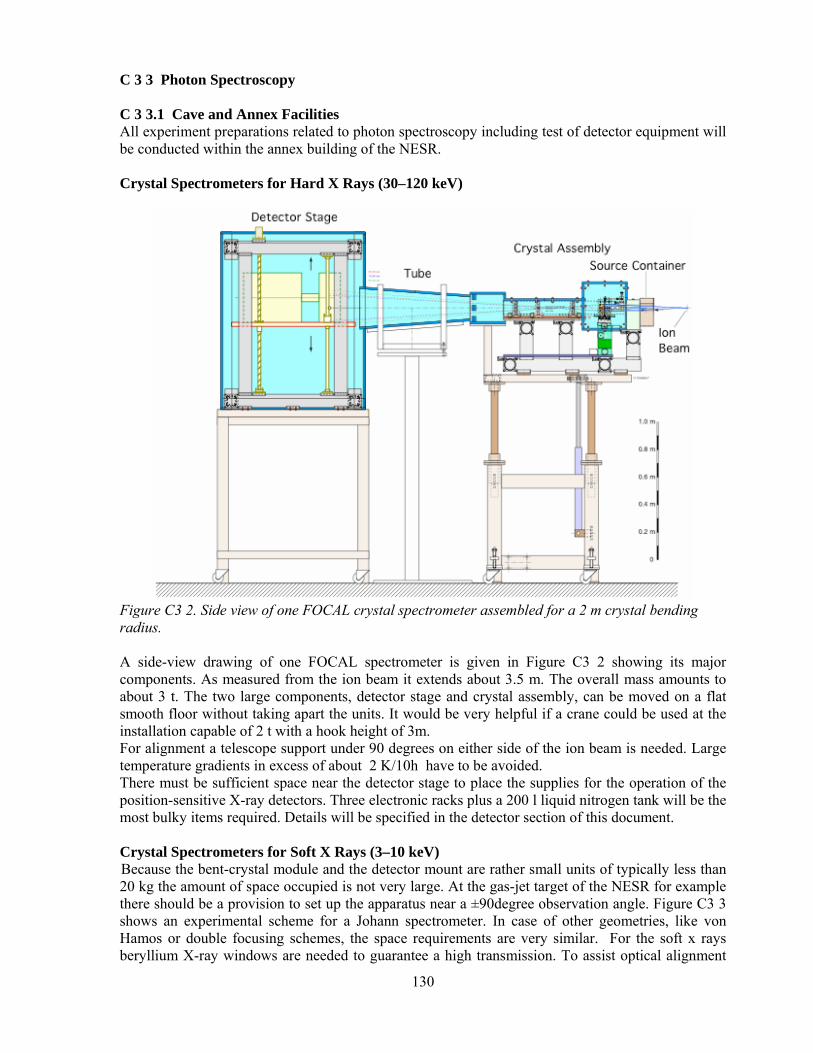
130
C 3 3 Photon Spectroscopy C 3 3.1 Cave and Annex Facilities All experiment preparations related to photon spectroscopy including test of detector equipment will be conducted within the annex building of the NESR. Crystal Spectrometers for Hard X Rays (30–120 keV)
Figure C3 2. Side view of one FOCAL crystal spectrometer assembled for a 2 m crystal bending radius. A side-view drawing of one FOCAL spectrometer is given in Figure C3 2 showing its major components. As measured from the ion beam it extends about 3.5 m. The overall mass amounts to about 3 t. The two large components, detector stage and crystal assembly, can be moved on a flat smooth floor without taking apart the units. It would be very helpful if a crane could be used at the installation capable of 2 t with a hook height of 3m. For alignment a telescope support under 90 degrees on either side of the ion beam is needed. Large temperature gradients in excess of about 2 K/10h have to be avoided. There must be sufficient space near the detector stage to place the supplies for the operation of the position-sensitive X-ray detectors. Three electronic racks plus a 200 l liquid nitrogen tank will be the most bulky items required. Details will be specified in the detector section of this document. Crystal Spectrometers for Soft X Rays (3–10 keV) Because the bent-crystal module and the detector mount are rather small units of typically less than 20 kg the amount of space occupied is not very large. At the gas-jet target of the NESR for example there should be a provision to set up the apparatus near a ±90degree observation angle. Figure C3 3 shows an experimental scheme for a Johann spectrometer. In case of other geometries, like von Hamos or double focusing schemes, the space requirements are very similar. For the soft x rays beryllium X-ray windows are needed to guarantee a high transmission. To assist optical alignment

131
there should be telescope supports for the direction perpendicular to the ion beam.
Figure C3 3. Side view of a crystal-spectrometer scheme for soft x rays. X-ray Optics The X-ray optics proposed for the experiments at the NESR, being small size inactive devices, do not need extra space, civil engineering, conditioning and supplies. C 3 3.2 Detector–Machine Interface Crystal Spectrometers for Hard X Rays (30–120 keV) The apparatus does not need any vacuum and will be installed completely separated from the accelerator vacuum vessel. For calibration a small movable vacuum pocket with thin stainless-steel X-ray windows should be implemented allowing to accurately position small probes of radioactive sources at the intersection of ion beam and gas jet. Crystal Spectrometers for Soft X Rays (3–10 keV) The apparatus to be installed will be separated from the accelerator vacuum using beryllium foils as windows. For the side-on observation at the gas jet the apparatus to be installed will not be interferring with the gas-jet facility. At the electron cooler or at the electron target an observation near 0 or 180 degrees is planned. For this purpose one has to install a curved crystal close to the ion beam which needs a special design of a vacuum pocket with an X-ray window. Details of the geometry will be worked out by ray tracing. Preliminary considerations suggest to have a vacuum chamber down- and up-stream the electron target providing an option for installing an analyzer crystal which deflects the x rays by an angle that is within the range of 50 to 110 degrees. X-ray Optics The polycapillary X-ray focusing optics (PXFO) and the multilayer X-ray focusing lens (MXFL) will be installed outside of the vacuum system as the elements of X-ray detectors mounted close to the gas target. The total reflection cylindrical mirror (TRCM) will be mounted in the ring vacuum (collinearly with respect of ion beam axis) just after the electron target. This solution will assure

132
efficient X-ray focusing on the beam axis, possible after the straight section of the ring (possible off-axis geometry will also be studied). These arrangements ask for taking into account, at the vacuum pipe/chamber designing stage, the presence of total reflection cylindrical mirror (TRCM) with allocated space for X-ray off-axis and on-axis (after bending magnet) detectors. µ-strip detectors, Compton polarimeter, calorimeter All these detectors have in common that the interface to the beam lime is defined by the scattering chamber. In general, view ports equipped with thin Beryllium or stainless steel windows are required. C 3 3.3 Photon Spectroscopy Crystal Spectrometers for Hard X Rays (30–120 keV) An area of about 60 m2 will be needed to assemble and test the apparatus prior to the final installation. This area should be equipped with a crane plus the supplies needed for operation of the the detectors. Crystal Spectrometers for Soft X Rays (3–10 keV) The space needed for assembling the apparatus and for offline test measurements could be found in a shared lab with the hard-xray spectroscopy. X-ray Optics Before installation in the ring the total reflection cylindrical mirror (TRCM) as well as poly-capillary X-ray focusing optics (PXFO) and the multilayer X-ray focusing lens (MXFL) will be tested using stand-alone set-ups. Consequently, the quality tested instruments will be installed in the ring. The polycapillary and multilayer lenses are small instruments (less ½ meter, less than 1 kg), while the cylindrical mirror (TRCM) (shaped thin metallic pipe: 1m length x 80-100 mm diameter, weight with mountings/adjustments less than 10 kg). The polycapillary X-ray focusing optics (PXFO) and the multilayer X-ray focusing lens (MXFL) will be installed outside the ring vacuum as the X-ray detector components. The total reflection cylindrical mirror (TRCM) has to be mounted in ring vacuum pipe, collinearly with the ion beam axis, next to the electron target. Installation of TRCM needs adjustment and test to be used in the experiments. µ-strip detectors and Compton polarimeter Assembling of the detector systems and performance tests will take please in the annex building of the NESR. The detector will be positioned at the experiment location (internal target or electron target) by cranes. Here dedicated support structures for the individual detectors systems must be available allowing for an accurate positioning with respect to the X-ray view ports. C 3 4 Electron Spectrometer at the Internal Target standard equipment for handling weights of < 1t, space 4 x 5 m around internal target according to figure of geometry. a. electronic racks 2x 19” racks b. cooling of detectors not applying c. ventilation no special need.

133
d. electrical power supplies < 5 kW (magnets) high voltage (~ 100 kV) – low current (<1mA) supply for e- gun. e. gas systems standard targets: N2, Xe, H2 , (He). no detector gases. f. cryo systems none 4.2 Detector –Machine Interface a. vacuum UHV – compatible detectors b. beam Pipe: operational requirements c. target, in-beam monitors, in-beam detectors internal jet target, projectile detectors. d. timing links between storage ring control and spectrometer control. e. radiation environment none f. radiation shielding standard ring shielding. 4.3 Assembly and installation a. Size and weight of detector parts, space requirements total: 5 x 4 m, Transporter magnet: 2 x 1,5 m, 200 kp HRS magnet: 2,5 x 2,5 m, ~ 1000 kp.. b. Services and their connections GSI – service with internal connections. c. Installation procedure no special requirements C 3 5 Extended Reaction Microscope C 3 5.1 Cave and Annex Facilities, Civil Engineering, Cranes, Elevators, Air Conditioning (Temperature and Humidity Stability requirements), Cooling, Gases a. access, floor plan, maxim. floor loading, beam height, crane hook height, alignment fiducials The reaction microscope is installed at the super-sonic jet target of the NESR and does not contain independent targets nor independent in the core unit. All its components conform to standards set by the NESR design group. The options of the design for the spectrometer as currently perceived with either a tilted linear geometry including Helmholtz coils of 2.5 m diameter spaced 1.25 m apart or the toroidal pancake coils requires a core –open area of 2m length along the beam path and a cross section area of 3m perpendicular to the beam direction. For the imaging forward electron
134
spectrometer—immediately following the core reaction microscope—a floor plan of 1.5m length times 3m for the instrument plus peripherals as pumps and diagnostic and electronics. Alignment fiducials on magnets permit positioning with respect to target center using NESR fiducials installed for the NESR supersonic jet target.
a. electronic racks a rack with space for 4 NIM/CAMAC crates is to be positioned in immediate proximity to the position sensitive detector of the forward spectrometer; another rack with 4NIM/CAMAC crates is to be positioned in immediate proximity of the detectors of the core reaction microscope at the jet target. b. cooling of detectors detectors do not need any provision for cooling c. ventilation : the ventilation for crates is provided by standard fan units in racks d. electrical power supplies for crates an electrical power of 4 kW is required. Independently for 2 turbomolecular pumps including forepumps and 2 sublimation pumps electric power of approximately 4 kW is required. e. gas systems does not apply- the experimental setup for the extended reaction microscope will use the supersonic gas jet installed in the NESR target region. f. cryo systems does not apply C 3 5.2 Detector –Machine Interface a. vacuum All components of the Extended reaction microscope conform to the vacuum specs of the NESR; the imaging forward electron spectrometer will be equipped with turbomolecular and Ti-pumps and will be designed to conform to the specs of the NESR b. beam Pipe the imaging forward electron spectrometer can be separated from the main NESR ring via full metal valves. c. target, in-beam monitors, in-beam detectors the reaction microscope chamber will contain ports for direct target observation using photomultipliers d. timing the extended reaction microscope requires fast timing signals from in-ring particle detectors which detect projectiles which underwent chare changing collisions, from the campus timing and system standard timing e. radiation environment no particular provisions are required for detectors involved f. radiation shielding does not apply

135
C3 1.5.3 Assembly and installation a. Size and weight of detector parts, space requirements the parts with the most mass will be the target chamber with core reaction microscope and the two dipole magnets, all other parts are significantly less massive:core reaction microscope target chamber: approximately 150kg 60 degree dipole magnet: 200kg space: up to 4m along beam line at target chamber; allowing for installation of a pair of Helmholtz coils 2.5m diam, 1.25m apart around the center of the jet; directly following the target chamber the first dipole of the imaging forward electron spectrometer will require 1.2m length along the beam and 2-3m width. b. Services and their connections As the first dipole magnets is inside the ring and is traversed by the coasting ion beam, its control must be completely integrated in the NESR beam control and guiding/focusing system. It has shown that it is advisable to have all beam optical elements of the spectrometer integrated the NESR control system. Signals on magnet field strength from Hall probes are read back into the experiment electronics. c. Installation procedure The entire instrument is to be installed inside the NESR by the NESR technical crew upon all acceptance tests and calibrations. C 3 6 Laser Spectroscopy C 3 6.1 Cave and Annex Facilities, Civil Engineering, Cranes, Elevators, Air Conditioning)
Figure C3 4. A location of the laser lab in the building corner close to the injection would allow a direct beam transport to the possible interaction regions.
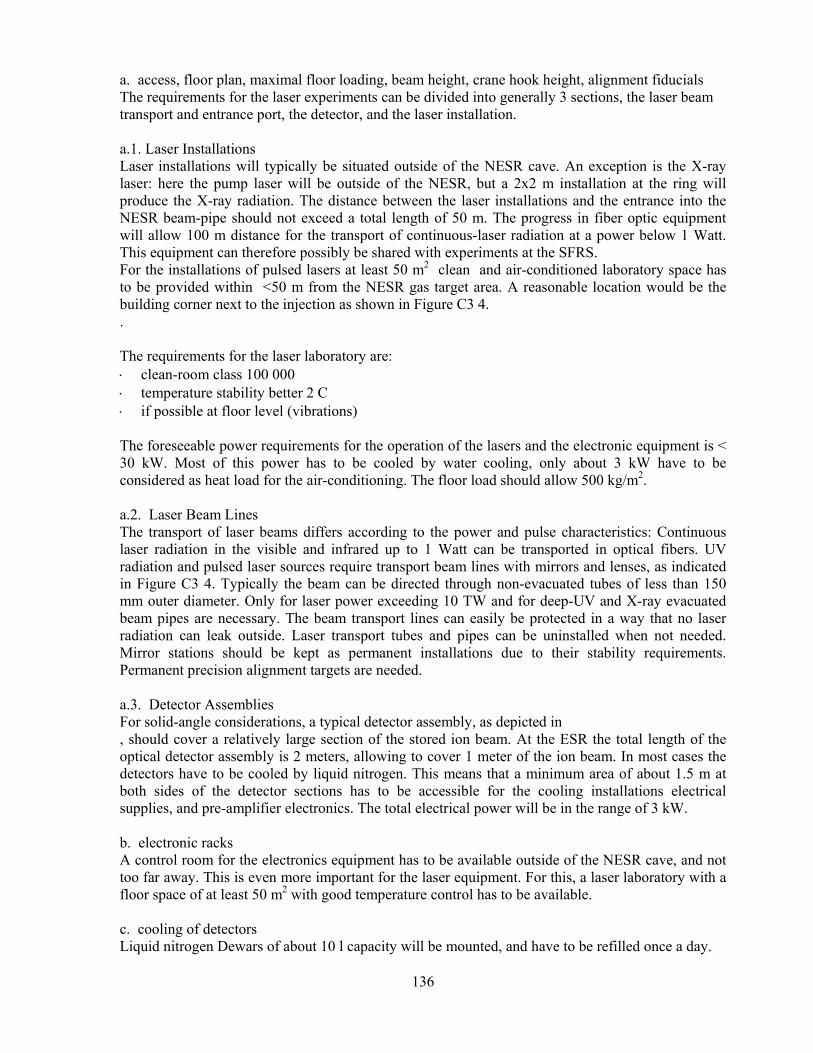
136
a. access, floor plan, maximal floor loading, beam height, crane hook height, alignment fiducials The requirements for the laser experiments can be divided into generally 3 sections, the laser beam transport and entrance port, the detector, and the laser installation. a.1. Laser Installations Laser installations will typically be situated outside of the NESR cave. An exception is the X-ray laser: here the pump laser will be outside of the NESR, but a 2x2 m installation at the ring will produce the X-ray radiation. The distance between the laser installations and the entrance into the NESR beam-pipe should not exceed a total length of 50 m. The progress in fiber optic equipment will allow 100 m distance for the transport of continuous-laser radiation at a power below 1 Watt. This equipment can therefore possibly be shared with experiments at the SFRS. For the installations of pulsed lasers at least 50 m2 clean and air-conditioned laboratory space has to be provided within <50 m from the NESR gas target area. A reasonable location would be the building corner next to the injection as shown in Figure C3 4. . The requirements for the laser laboratory are: ⋅ clean-room class 100 000 ⋅ temperature stability better 2 C ⋅ if possible at floor level (vibrations) The foreseeable power requirements for the operation of the lasers and the electronic equipment is < 30 kW. Most of this power has to be cooled by water cooling, only about 3 kW have to be considered as heat load for the air-conditioning. The floor load should allow 500 kg/m2. a.2. Laser Beam Lines The transport of laser beams differs according to the power and pulse characteristics: Continuous laser radiation in the visible and infrared up to 1 Watt can be transported in optical fibers. UV radiation and pulsed laser sources require transport beam lines with mirrors and lenses, as indicated in Figure C3 4. Typically the beam can be directed through non-evacuated tubes of less than 150 mm outer diameter. Only for laser power exceeding 10 TW and for deep-UV and X-ray evacuated beam pipes are necessary. The beam transport lines can easily be protected in a way that no laser radiation can leak outside. Laser transport tubes and pipes can be uninstalled when not needed. Mirror stations should be kept as permanent installations due to their stability requirements. Permanent precision alignment targets are needed. a.3. Detector Assemblies For solid-angle considerations, a typical detector assembly, as depicted in , should cover a relatively large section of the stored ion beam. At the ESR the total length of the optical detector assembly is 2 meters, allowing to cover 1 meter of the ion beam. In most cases the detectors have to be cooled by liquid nitrogen. This means that a minimum area of about 1.5 m at both sides of the detector sections has to be accessible for the cooling installations electrical supplies, and pre-amplifier electronics. The total electrical power will be in the range of 3 kW. b. electronic racks A control room for the electronics equipment has to be available outside of the NESR cave, and not too far away. This is even more important for the laser equipment. For this, a laser laboratory with a floor space of at least 50 m2 with good temperature control has to be available. c. cooling of detectors Liquid nitrogen Dewars of about 10 l capacity will be mounted, and have to be refilled once a day.
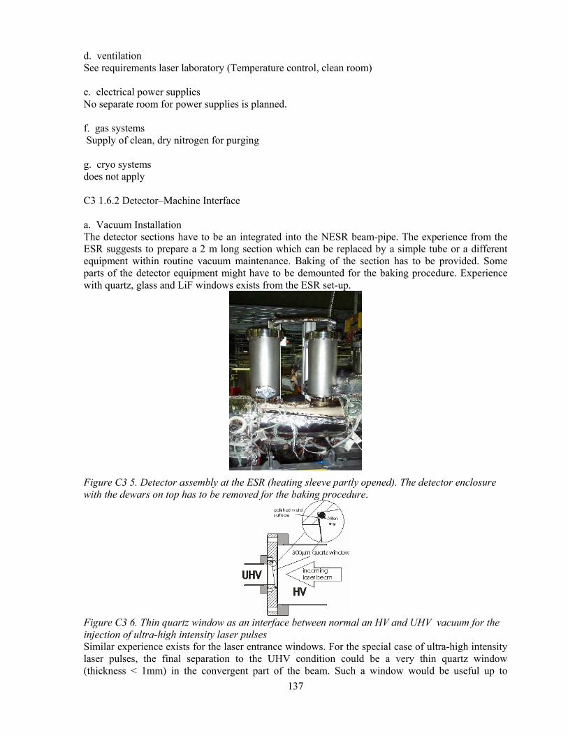
137
d. ventilation See requirements laser laboratory (Temperature control, clean room) e. electrical power supplies No separate room for power supplies is planned. f. gas systems Supply of clean, dry nitrogen for purging g. cryo systems does not apply C3 1.6.2 Detector–Machine Interface a. Vacuum Installation The detector sections have to be an integrated into the NESR beam-pipe. The experience from the ESR suggests to prepare a 2 m long section which can be replaced by a simple tube or a different equipment within routine vacuum maintenance. Baking of the section has to be provided. Some parts of the detector equipment might have to be demounted for the baking procedure. Experience with quartz, glass and LiF windows exists from the ESR set-up.
Figure C3 5. Detector assembly at the ESR (heating sleeve partly opened). The detector enclosure with the dewars on top has to be removed for the baking procedure.
Figure C3 6. Thin quartz window as an interface between normal an HV and UHV vacuum for the injection of ultra-high intensity laser pulses Similar experience exists for the laser entrance windows. For the special case of ultra-high intensity laser pulses, the final separation to the UHV condition could be a very thin quartz window (thickness < 1mm) in the convergent part of the beam. Such a window would be useful up to

138
> 10 TW/cm2 power density, roughly two orders of magnitude higher than at a normal thickness vacuum window. Laser window and mirrors should be accessible independent of the NESR vacuum by a separating valve. These sections have to be pumped down independently from the main vacuum. b. beam pipe The geometrical situation at the NESR is still not fully clarified, since access at the dipole magnets is more restricted than at the ESR. For this reason it might be necessary to inject the laser beam from top or bottom and make a final turn by a compact mirror assembly, which could be mounted within the vacuum. The details have to be studied together with the dipole magnet design. It should be noted, that a similar problem exists for particle detectors. c. target, in-beam monitors, in-beam detectors Detectors for the beam position of both the ion and the laser beam have to be integrated into the NESR. d. timing At least for the pulsed laser interaction, synchronization between the circulating bunch and the laser pulse has to be established. Experience from ESR experiments can be used. The procedure requires a synchronous timing signal from the buncher HF. In addition, other essential beam conditions have to be available. C 3 5.3 Assembly and Installation a. Size and weight of detector parts, space requirements The detection sections will be prepared separately, and installed – for relatively long periods – into the beam line. A typical dimension will be: Length: 2m Weight: 200 kg The assembly has to be done outside of the NESR at some appropriate clean workshop. b. Services and their connections Some parts of the detectors will be outside of the vacuum, and will need occasional replacement. Some detectors will need liquid nitrogen cooling during the experiments, or include a water cooled chiller unit. Mirrors inside the vacuum will have to be checked regularly for defects. This can be done visually through the entrance window. In case of defects, replacement requires braki
c. Installation procedure Installations at the NESR vacuum system will be bakeable. The installation will require dismounting of some of the external parts (detectors, mirrors) . Putting the detector sections into place will require some lifting device.

139
C 4 Cooled, Decelerated and Extracted Ions C 4 1 Low-Energy Experimental Area C4 1.1 Cave and Annex Facilities a. This hall will have an area of 20 x 15 m2 where two experimental setups will be mounted. One around the magnetic spectrometer and the second one for beams of beams of slow HCI from HITRAP.
Figure C4 1. Artist view of the F1 experimental area at FLAIR. The proposed positioning of the low energy HCI experimental area inside the FLAIR building permits to access beams coming directly from the NESR, from the LSR and HITRAP. The beam axis inside the cave will be placed in 1.5 m height For experiments with very low energy ions extracted from HITRAP (ion-surface interactions, collisions, etc.) it is necesary to change the positin of the magnet. For this a special mouving system must be designed. The cave clearing must be 5 m. This height will permit the installation of two fix cranes (1000 and 2000 kg) in the region of the target chamber and close to the spectrometer. The floor will have a maximum loading in the region of the magnet separator (maximum 2 t/m2). The access into the cave will by permitted through a labyrinth and the area must be closed during the beam time. Alignment fiducials for the spectrometer, beam line and target chamber, are required. The whole setup including the transport beam line from the NESR must be aligned relative to the FAIR facility. For regular alignments of different parts of the setups, diagnosis detectors, etc. a telescope placed at the end of the cave having a permanent, reproducible alignment is requested. b. The cave must accommodate four to six electronic racks for detectors read out electronics, vacuum controlling, remote control of the diagnosis elements, etc. For this an area of 6 m2 is needed. The estimated electrical power needed in cave for electronics is about 12 kW. Additional 10 kW is needed for all other equipment.
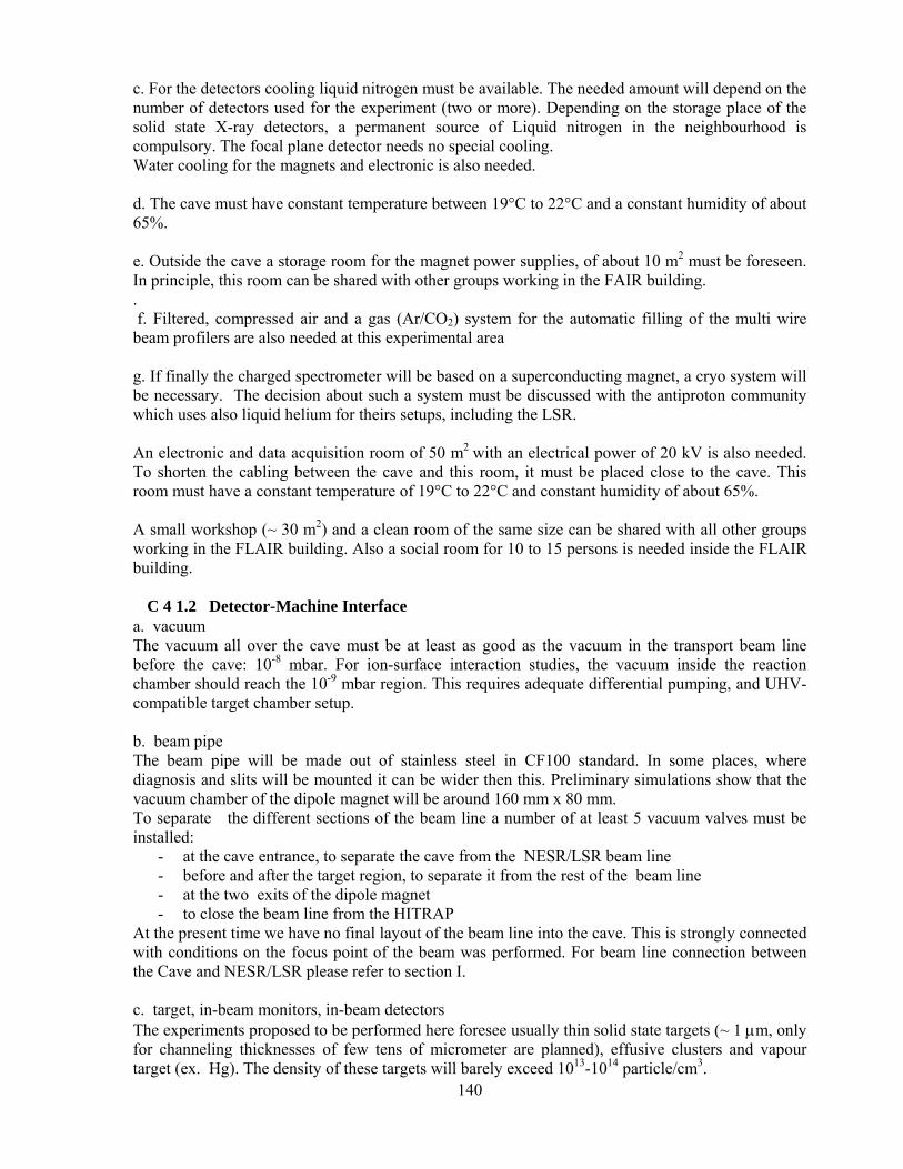
140
c. For the detectors cooling liquid nitrogen must be available. The needed amount will depend on the number of detectors used for the experiment (two or more). Depending on the storage place of the solid state X-ray detectors, a permanent source of Liquid nitrogen in the neighbourhood is compulsory. The focal plane detector needs no special cooling. Water cooling for the magnets and electronic is also needed. d. The cave must have constant temperature between 19°C to 22°C and a constant humidity of about 65%. e. Outside the cave a storage room for the magnet power supplies, of about 10 m2 must be foreseen. In principle, this room can be shared with other groups working in the FAIR building. . f. Filtered, compressed air and a gas (Ar/CO2) system for the automatic filling of the multi wire beam profilers are also needed at this experimental area g. If finally the charged spectrometer will be based on a superconducting magnet, a cryo system will be necessary. The decision about such a system must be discussed with the antiproton community which uses also liquid helium for theirs setups, including the LSR. An electronic and data acquisition room of 50 m2 with an electrical power of 20 kV is also needed. To shorten the cabling between the cave and this room, it must be placed close to the cave. This room must have a constant temperature of 19°C to 22°C and constant humidity of about 65%. A small workshop (~ 30 m2) and a clean room of the same size can be shared with all other groups working in the FLAIR building. Also a social room for 10 to 15 persons is needed inside the FLAIR building.
C 4 1.2 Detector-Machine Interface a. vacuum The vacuum all over the cave must be at least as good as the vacuum in the transport beam line before the cave: 10-8 mbar. For ion-surface interaction studies, the vacuum inside the reaction chamber should reach the 10-9 mbar region. This requires adequate differential pumping, and UHV-compatible target chamber setup. b. beam pipe The beam pipe will be made out of stainless steel in CF100 standard. In some places, where diagnosis and slits will be mounted it can be wider then this. Preliminary simulations show that the vacuum chamber of the dipole magnet will be around 160 mm x 80 mm. To separate the different sections of the beam line a number of at least 5 vacuum valves must be installed:
- at the cave entrance, to separate the cave from the NESR/LSR beam line - before and after the target region, to separate it from the rest of the beam line - at the two exits of the dipole magnet - to close the beam line from the HITRAP
At the present time we have no final layout of the beam line into the cave. This is strongly connected with conditions on the focus point of the beam was performed. For beam line connection between the Cave and NESR/LSR please refer to section I. c. target, in-beam monitors, in-beam detectors The experiments proposed to be performed here foresee usually thin solid state targets (~ 1 µm, only for channeling thicknesses of few tens of micrometer are planned), effusive clusters and vapour target (ex. Hg). The density of these targets will barely exceed 1013-1014 particle/cm3.

141
Part of the today GSI standard beam diagnosis can be considerd also in the future. Although it is beam destructive, for beam transport purposes is a good option. The fluorescent screen method, scintillators, and gas profiler are needed as viewer and beam profile monitors. For beams with energies below 10 MeV/u, the GSI standard profilr monitors, the gas-filled chambers, will be difficult to use, due to the presence of a window. More R&D is required in this direction. One solution is the digital readout of fluorescent screens, which will permit the determination of the beam profile. The accuracy of this measurement is mainly dependent on the screen properties. For beam-intensity monitoring, a different solution will be sought. The development of the focal plane detector will offer a spin-off also for beam diagnosis. Such a detector will perform simultaneously two tasks, imaging and intensity monitoring. The beam monitoring aspects will be discussed in the larger FLAIR context. It is obvious that general solutions will be searched for. This will assure a general standard and will be cost saving. For special local requirements (beam energy, beam intensities, in-ring monitoring) special solutions will be found. Therefore, a common action with the GSI Diagnosis Group is anticipated. At least four beam monitors are needed in the cave:
- two upstream the target, separated by minimum 2 m, the second one being as close as possible to the target.
- a third one at the end of the beam line at zero degree exit of the dipole magnet, and - the fourth one at the end of the deviated beam line.
Due to the relatively low beam intensity expected in this area, there are no special aspects related to the radiation damages and safety. It is desired, that the detectors for the beam diagnosis in the cave will be similar to the detectors used for the beam diagnosis all over the new accelerator. The only detector exposed to the full beam intensity, for longer time, will be the projectile detector placed in the focal plane of the spectrometer. The radiation hardness aspects related to it have been mentioned in the section B4 1.1. d. timing In this cave slow extracted NESR/LSR heavy ion beams will be used. The experiments will take every spill and a correlation of the data acquisition with the beginning and the end of the spill will improve the accuracy of the measurements. e. radiation environment Although the radiation level during the experiments will be higher then the accepted safety limit, no tremendous levels are expected here, due to the limited beam intensity and energy range. For more details please refer to section F, Safety. f. radiation shielding The aspects connected to the radiation hardness of focal plane detector have been mentioned in the section B4. No additional shielding for the particle or X-ray detectors installed for the different experiments is foreseen. If in some special cases additional shielding of the detectors is needed, mobile Lead walls will be locally installed. C4 1.3 Assembly and installation a. size and weight of detector parts, space requirements In this cave, different and relative small experiments will be performed. Usually, the target region will change from experimental to experiment. It is planned to mount and test parts of the different experiments in a space placed close to the cave. For this purpose, an area of 60 m2 which will serve also as storing place for different experimental setups, detectors and electronics is necessary. The parts to be mounted have reduced dimensions. No crane for mounting is needed and the transport to the experimental place will be done on racks.
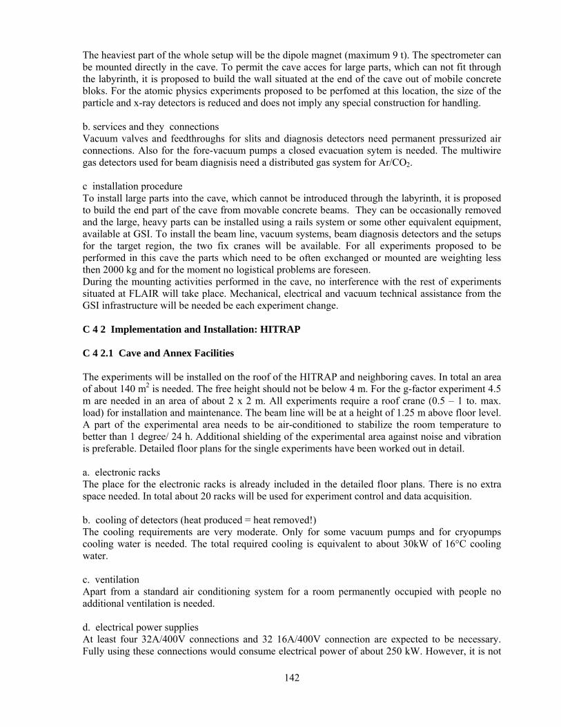
142
The heaviest part of the whole setup will be the dipole magnet (maximum 9 t). The spectrometer can be mounted directly in the cave. To permit the cave acces for large parts, which can not fit through the labyrinth, it is proposed to build the wall situated at the end of the cave out of mobile concrete bloks. For the atomic physics experiments proposed to be perfomed at this location, the size of the particle and x-ray detectors is reduced and does not imply any special construction for handling. b. services and they connections Vacuum valves and feedthroughs for slits and diagnosis detectors need permanent pressurized air connections. Also for the fore-vacuum pumps a closed evacuation sytem is needed. The multiwire gas detectors used for beam diagnisis need a distributed gas system for Ar/CO2. c installation procedure To install large parts into the cave, which cannot be introduced through the labyrinth, it is proposed to build the end part of the cave from movable concrete beams. They can be occasionally removed and the large, heavy parts can be installed using a rails system or some other equivalent equipment, available at GSI. To install the beam line, vacuum systems, beam diagnosis detectors and the setups for the target region, the two fix cranes will be available. For all experiments proposed to be performed in this cave the parts which need to be often exchanged or mounted are weighting less then 2000 kg and for the moment no logistical problems are foreseen. During the mounting activities performed in the cave, no interference with the rest of experiments situated at FLAIR will take place. Mechanical, electrical and vacuum technical assistance from the GSI infrastructure will be needed be each experiment change. C 4 2 Implementation and Installation: HITRAP C 4 2.1 Cave and Annex Facilities The experiments will be installed on the roof of the HITRAP and neighboring caves. In total an area of about 140 m2 is needed. The free height should not be below 4 m. For the g-factor experiment 4.5 m are needed in an area of about 2 x 2 m. All experiments require a roof crane (0.5 – 1 to. max. load) for installation and maintenance. The beam line will be at a height of 1.25 m above floor level. A part of the experimental area needs to be air-conditioned to stabilize the room temperature to better than 1 degree/ 24 h. Additional shielding of the experimental area against noise and vibration is preferable. Detailed floor plans for the single experiments have been worked out in detail. a. electronic racks The place for the electronic racks is already included in the detailed floor plans. There is no extra space needed. In total about 20 racks will be used for experiment control and data acquisition. b. cooling of detectors (heat produced = heat removed!) The cooling requirements are very moderate. Only for some vacuum pumps and for cryopumps cooling water is needed. The total required cooling is equivalent to about 30kW of 16°C cooling water. c. ventilation Apart from a standard air conditioning system for a room permanently occupied with people no additional ventilation is needed. d. electrical power supplies At least four 32A/400V connections and 32 16A/400V connection are expected to be necessary. Fully using these connections would consume electrical power of about 250 kW. However, it is not
143
realistic that 100% of the theoretically available power is going to be used; a more realistic rate is 50% and thus 125 kW. The number of connections is also due to conveniences. e. gas systems Pressurized air is needed with a pressure of up to 20 bar. Additionally N2 will be used to vent the vacuum vessels and to pressurize LN2 vessels. Special gases as for instance Ar, Xe or Kr will only be needed in small amount and can be supplied from gas bottles. f. cryo systems A LN2 cooling of the target for the surface interaction studies is required for some measurements. Additional LN2-cooling might be necessary in case of using X-ray detectors. The two superconducting magnets for the mass measurement experiment and the g-factor experiment need both LN2 and LHe. Thus, a permanent helium recovery line and a fixed liquid nitrogen line should be installed and connected to three of the experimental areas. The cryogenic four-trap system for mass measurements will be installed in a cryogenic-free cold head cryostat. C 4 2.2 Detector –Machine Interface a. vacuum Since the experiments will be performed with HCI special care on the vacuum is required. Baking of all setups in situ is foreseen in order to reach a pressure of ~10-10 mbar. Inside the cryogenic trap systems, a vacuum of better than 10-14 mbar is provided by the cryopumping effect. The connection to the HITRAP cooler trap will be done via UHV beam lines (10-10 mbar) in order to keep the good vacuum that is maintained in the cooler trap. b. beam pipe There is no direct connection of the experiments to the beam lines coming from the storage rings. The only link is via the decelerator/cooler trap setup. c. target, in-beam monitors, in-beam detectors Reaction microscope: Beam intensity and/or profile monitors are required to control and optimize beam transport to the reaction microscope, according to the beam requirements mentioned above. If necessary we will provide a set of XY collimating slits located at the entrance of the reaction microscope (Figure B4 5). Surface interaction studies: A good control of the ion beam is required to adjust it for ion-surface scattering experiments. In-beam monitors, deflection and focusing elements as close as possible to the experiment are advisable. For precise beam definition, we will include four-fold slit elements in front of the set-up. X-ray spectroscopy: Multi-Channel-Plate detectors will be used to optimize and control beam transport between the HITRAP cooler trap and the X-ray target chamber. g-Factor measurements: No targets foreseen, inexpensive charge collectors (Faraday Cups) for use as in-beam monitors. Mass measurements: Multi-Channel-Plate detectors will be used to optimize and control beam transport between the HITRAP cooler trap and the precision mass spectrometer. d. timing Standard system timing and campus timing will be needed. The timing will be determined by the ion pulse structure as given by the cooler trap which decouples the experiments from the accelerator complex and timing. Existing and well investigated timing systems will be used for internal timing. e. radiation environment

144
The experimental area should be shielded as good as possible against radiation from the accelerators and beam stops etc. in order to minimize the background on the detectors. This also implies that the experimental area is not considered to be a radiation environment presenting hazards to the people working there. f. radiation shielding Since the experiments are performed with only a few ions no shielding is needed. There is no other source of hazardous radiation that needs to be shielded. C 4 2.3 Assembly and installation All experimental setups are prepared, i.e. mounted and tested at the home institutes. The reaction microscope and the projectile analyzer have been assembled and tested at Max-Planck-Institute in Heidelberg. The final installation at HITRAP will be done after all parts are tested and specified. Permanent access is needed. The Penning trap setup for the g-factor measurements will be assembled and tested at the Institute of Physics at the University of Mainz. The final installation in the FLAIR building will be done after all parts are tested and specified. Permanent access to the setup is needed. The components (equipment) of the collision chamber for the X-ray spectrometry will be assembled and tested at the Institute of Physics of the University in Cracow. The final installation at HITRAP will be done after all parts are tested and specified. Permanent access is needed. The Penning trap mass spectrometer will be assembled and tested at the institute of physics at the University of Mainz. The final installation in the cave will be done after all parts are tested and specified.. Permanent access is needed. a. Size and weight of detector parts, space requirements The proposed setup for the reaction measurements consisting of the reaction microscope, the projectile analyzer, the gas jet and the vacuum system has a weight of about 600-800 kg. The largest and heaviest part of the surface interaction studies setup is the recipient chamber with approximately 200 kg. All other parts have less than 100 kg of weight. The recipient will have a diameter of approximately 80 cm and a height of about 60 cm. The total weight of pumps and beam line components have a weight of about 100 -200 kg for the X-ray spectroscopy setup. The superconducting magnet is the heaviest individual piece of the g-factor setup and weighs about 800 kg. The cryogenic trap system has a weight of about 40 kg. Also for the mass measurement setup the superconducting magnet is the heaviest part with about 500-800 kg. The cryogenic trap system including FT-ICR detector has a weight of about 300 kg. Again the superconducting magnet is the heaviest part with a weight of about 500 to 750kg. Typical values for the weight of the optical bench lie between 100 and 250kg. It is therefore sensible to assume something in the range of 600 to 1000 kg for the weight of the equipment. These two components comprise the bulk of the weight for our equipment. b. Services and their connections For the pumps, constant water flow is required; the valves need permanent pressurized air. Yearly maintenance is required for the pumping system. The superconducting magnet needs regular service, including twice a week filling of LN2 (liquid Nitrogen) and about once a month filling of LHe (liquid Helium). A permanent LN2 line and a LHe recovery line will be requested, also a lifting ramp for lifting up the liquid Helium vessels regularly up to the magnet, if located above zero-level. c. Installation procedure
145
Reaction microscope: As described above, the whole device has been first installed and tested at the Max-Planck-Institut in Heidelberg. The final installation in the cave can be done within one month. Surface interaction studies: The experiment can be divided in several subcomponents which can be handled quite independently from each other. These subcomponents are: ⋅ Installation of recipient including target manipulator and pumping station. ⋅ Installation of transfer and preparation section. ⋅ Mounting of the several detectors. All devices and parts will be tested before mounting at the contributing institutes. It is planned to install the recipient with basic equipment for surface preparation and electron detection first. In a later stage additional features will be added. The basic installation is estimate to require 6 months, the total installing in the cage 18 months. X-ray spectroscopy: The final installation in the cave can be done within one year. Stringent alignment of the beam line and all the target components is required. g-Factor measurements: As described above, the whole device will be first installed and tested at the University of Mainz. The final installation in the cave can be done within two years. Mass measurements: As described above, the whole device will be first installed and tested at the University of Mainz. The final installation in the cave can be done within two years. Laser spectroscopy: We will assemble the trap and equipment before final installation to the cave.

146
D Commissioning D 1 Laser Spectroscopy and Laser Cooling at SIS100/300 a. magnetic field measurements Not applicable. b. alignment The three types of laser experiments have a common structure, with four essential components: the laser system, the laser beam transport to the experiment, the combined geometry of laser and ion beam within the synchrotron, and detectors. Commissioning of the laser system is independent of the accelerator operation. This is also the case for set-up and calibration of the X-ray spectrometer. The laser beam transport to the experiment is depending on the status of the accelerator due to safety procedures and interlocks. It can be prealigned off-line, but has to be checked prior to operation. A critical issue is the overlap between ion and laser beam within the synchrotron. For the alignment procedure targets have to be prepared that allow to preset the laser position pointing very close to the anticipated ion beam trajectory. The laser beam will be fixed to this trajectory by an active feedback system. Finally a precise positioning with an accuracy better than 1 mm is necessary. A very reliable fine tuning of the relative position of ion and laser beam can be established by observation of fluorescence at two positions with a very large separation. Provided that the ion beam trajectory is within the viewing angle of the laser entrance windows, the alignment can be done only by laser adjustments. The positioning of the florescence detectors is less demanding. c. test runs Test runs are necessary to ensure optimization of the stripper foil and the fine tuning of the beam in the interaction region. D 2 Ion-Beams from SIS12/SIS100 a. magnetic field measurements The FRS magnets have been mapped extensively. b. alignment The magnetic spectrometer has to be aligned, the requirements regarding precision are typically a few mm. In contrast, the alignment of the set-ups for the channelling experiments is rather complicated. However, the technique is well known from similar experiments in the existing Cave A. c. test runs Test runs will be necessary for the commissioning of the magnetic spectrometer. Since the operation of the magnets is known in detail from the FRS, the test runs will probably be rather short. D 3 Atomic Physics Experiments at the NESR D 3 1 Electron Target a. magnetic and electric filed measurements The magnetic field of the solenoid part has to be mapped carefully prior to assembling the electron target in order to check whether correction coils will be needed.

147
The electron high voltage will have to be calibrated in close collaboration with the Physikalisch-Technische Bundesanstalt PTB in Braunschweig. This holds also for the lower voltages of the 450 kV main electron cooler. The electron beam intensity and intensity distribution will be calibrated with standard methods. b. alignments Special care has to be taken to ensure a proper mechanical alignment that runs in parallel with the solenoid magnetic filed lines. Special care has also to be taken to check the alignments of the ion and electron beams of both coolers and two establish a suitable modus operandi for future measurements. c. test runs ⋅ The electron target will be commissioned with stable beams in the framework of the NESR
commissioning. ⋅ Test runs are needed in order to investigate the stability of the ion beam for the case of an
electron target energy close to the electron cooler one. This is also an R&D task that will be started at TSR by the Heidelberg group in the near future.
⋅ Test runs are also needed to investigate the stability and the transversal temperature of the electron targets by measuring known low-lying DR resonances, their position and line shape. This will be also done for known DR-resonances at higher relative energies for the determination of the transverse electron temperature as well as of the ion beam temperature.
⋅ The calibration of the high voltages will be fine tuned with DR resonances that are subject to a R&D topic of the Giessen group (cf. e.g. the corresponding chapter with the task distribution among the collaboration.)
D 3 2 Internal Jet-Target A lot of experience exists from the operation of the internal jet target at the ESR. Most of the pre-alignment and pre-adjustment can be done without ion beams. For the final positioning, test runs with ions are necessary, which can be parasitic together with other experiments. D 3 3 Photon Spectroscopy X-ray Spectrometer for Hard and Soft X-rays, Calorimeter Because both spectrometers (including the 2D µ-strip detectors) will have been thoroughly explored during the ESR experiments there will only be a short commissioning of one beam time of one week necessary. X-ray Optics Developed X-ray focusing optics after construction and successful quality tests have to be tested in-beam in the NESR ring. In such test measurements mainly X-ray optics alignment and focusing capabilities will be addressed for stored ion beams in the ring. For these test it is necessary to have two times short beam time (2 days) with half a year in between to have additional time to introduce possible refinements and corrections. µ-strip detectors (see also X-ray spectrometer for hard and soft X-rays) Test experiments using the prototype 2D detector are already planned for the ESR storage ring. In addition, for the accurate determination of the response characteristics for these detectors (accuracy in position determination etc.) a beam time request at the ESRF synchrotron facility in Grenoble has been approved. A first run is expected to take place within the first half of 2005. Further test experiments will be conducted in a parasitic mode at the ESR internal target.

148
Compton Polarimeter For the accurate determination of the response characteristics for the Compton telescope detectors (accuracy in position determination, polarization sensitivity etc.) beam times will be requested at the ESRF synchrotron facility in Grenoble. In addition, further test experiments will be conducted in a parasitic mode at the ESR internal target. D 3 4 Electron Spectroscopy at the Internal Target First the spectrometer components will be tested with calibrated electron sources in the laboratory set up place. Than test beams of 2 x 4 days will be requested in order to proceed the commissioning phase. This also will detect possible unexpected effects in operation with storage ring beams. a) magnetic field measurements Magnetic fields will be in the range of up to 400 Gm and will be controlled by Hall probes. Possible effects for the circulating ion beam are compensated by correcting magnets. b) alignment Does not apply c) test runs (compare section B3 1.4) D 3 5 Extended Reaction Microscope a) magnetic field measurements Magnetic field mapping will be part of the purchase agreement with the manufacturer and will be confirmed at the local GSI magnet test facility as has been executed successfully with the magnets for the current spectrometer. b) alignment Alignment tooling will be part of the purchasing contract for all electro -optical elements as well. The alignment procedure for the spectrometer components in location is a well established procedure. c) test runs Test runs will be performed for the assembled system after the appropriate tests of all individual components have been executed successfully. Test runs with radioactive sources for calibration and confirmation of optical mapping have been performed. After these tests we will request beam periods of three shifts in location. D 3 6 Laser Experiments a) magnetic field measurements Does not apply b) alignment For each of the experiments the commissioning divides into four sub-tasks: ⋅ Preparation of the laser system ⋅ Preparation of laser beam transport and laser safety ⋅ Ensuring overlap between laser and ion / electron beam ⋅ Set-up and test of the detector suite

149
The preparation of the laser systems is to a large degree independent of the storage ring, since most of the laser installations are situated outside of the ring. Work inside of the NESR cave will only be necessary in the case of the ultra-high intensity and X-ray laser experiments, because here the (passive) pulse compressor and X-ray laser target have to be close to the injection point. The laser beam transport within the NESR cave will be set-up as a remotely controlled and monitored system. The laser safety installations, shutters and interlocks, are integral part of this system. Commissioning will require thorough alignment and testing. Due to laser safety issues, this requires to some part exclusive access to the NESR cave. Experience from the ESR and TSR experiments show that a lot of effort is needed to ensure reliably a good overlap between ion and laser beam. For this issue it has to be possible to inject the laser beams into the NESR experimental sections under conditions, where access to the NESR cave is allowed, i.e. where radiation safety cups are not in the beam. The specific detector suites (optical and X-ray detectors) will be tested before installation into the NESR. c) test runs Specific commissioning beam time will be needed to ensure the relative positioning of laser and ion beam. After installation of the detectors into the beam-line parasitic beam-time should be available to test and minimize background influence from the ion beam. D 4 Cooled, Decelerated and Extracted Ions D 4 1 The Low-Energy Cave The magnetic field of the magnets from the spectrometer has to be carefully mapped. If the present target hall at the SIS18-ESR accelerator will be not decommissioned before 2009, the new magnet spectrometer can be tested in the present cave for atomic physics experiments with heavy ion beams from SIS. The final alignment of the spectrometer, the beam line and the reaction chamber will be performed in the new cave, after installation. The requested precision in alignment for the channeling experiments is below one mm. For the alignment of the full setup, the help of professionals is demanded. Test runs for different experiments (channeling, ion-surface interaction, ion-cluster interaction) are needed. These tests can be performed with beams from LSR and/or NESR. A preliminary time schedule of the commissioning is presented in the table in section G 4. D 4 2 HITRAP a) Magnetic field measurements Magnetic field measurements with a NMR or Hall probe are required for the HITRAP cooler trap and the Penning trap experiments utilizing superconducting magnets. For all the other experiments such measurements are not required. b) Alignment: For the HITRAP cooler trap and the Penning trap experiments the alignment of the magnetic-field axis is very important since the injection of the highly-charged ions into the strong magnetic field is extremely critical. The HITRAP decelerator requires careful mechanical alignment during the production process. Alignment of the particle beams will be done by steerer magnets at the HITRAP facility. The alignment of the reaction microscope setup on the axis of the HCI beam is crucial. For the ion-surface interaction experiments alignment is of great importance to have good beam control. For the X-ray spectroscopy the alignment of the setup is crucial since the injection of the highly-charged
150
ions into the gas target area is extremely critical. In general standard alignment marks are expected to be available. However, help by an expert is requested for the alignment of the setup at its final position in the cave. c) Test runs The HITRAP decelerator and the cooler trap will be commissioned with beam from the ion injectors of the LSR at 4 MeV/u, ion species: protons, H- ions, and light highly charged ions, e.g. Ar16+. Final commissioning will be done with highly charged heavy-ion beams up to uranium U92+ at 4 MeV/u from NESR and with antiprotons at 4 MeV from LSR/CRYRING. Reaction microscope: After final installation in the cave, test runs with any HCI beam of intensity of at least 104 ions/s, focussed on 1 mm2 are required. Under these conditions, 2 beamtimes of approx. 2 days each would be sufficient. Only a very limited amount of shifts for test runs will be requested. Ion-surface interaction experiments: For beam steering and testing as well as calibrating we will require several test beams of singly and multiply-charged ions. Also, molecular test beams might be used for calibration of the TOF- and of the TOF-SIMS mass spectrometer. X-ray spectroscopy: Test runs: after the final alignment a certain amount of shifts (about 20) for the test runs of the gas target, X-ray detectors and charge state analysers will be requested. g-factor measurements: an external ion source will be used for tests of the ion guidance system. Mass measurements: Since all tests can be performed with our off-line ion source or with highly-charged ions from the cooler trap only a very limited amount of shifts for test runs will be requested. Laser spectroscopy: Beams of highly charged ions with medium Z, e.g. 40Ca16+. This will be used for optimising the capture of ions from a beam and the implementation of the rotating wall technique for increasing the density of ions in the trap. 40Ca16+ is an example of an ion with a very similar charge to mass ratio as 207Pb81+. E Operation E 1 Laser Interactions with Highly Relativistic and Highly Charged Ions at SIS100/300 a. Operation of each of the sub-projects All laser experiments planned at SIS100/300 are in-beam experiments and therefore the merging of the laser and ion beams in the interaction section is crucial. Thus, after setting the synchrotron parameters, an individual optimization of this beam overlap should be possible. The experiments will be operated from the responsible physicists and parameter variations will mostly occur at the laser side. The lasers itself will be set-up in the laser laboratory. Ideally, once the synchrotron is set, the experiments will be controlled from the laser lab. The procedure for the synchrotron will be similar to a storage ring operation: after injection the ions will be bunched and accelerated to the necessary energy. If this energy is reached, the beam will be rebunched synchronized with the laser excitation. The typical cooling cycle only takes a few seconds. All experiment controls within the accelerator tunnel will be remotely controlled and monitored. Necessary cooling for detectors will be done in a way that no refilling is required. b. auxiliaries and c. Power, gas, cryo No additional infrastructure (power etc.) is needed besides for the running of the laser lab as described above.
E 2 Ion Beams from SIS12/100 a) of each of the sub-projects

151
After the construction phase the oversight over this experimental place should lay in the responsibility of SPARC, the biophysics and the material science collaboration represented by a cave responsible, permanently located at GSI. For the preparation, testing and performing of the different experiments, the responsibility over the experimental set-up will be on the group itself. It is requested that these groups get technical support, either from the SPARC collaboration itself, or from the GSI technical infrastructure, if needed. The present experience al GSI shows that the external groups must be assisted, with hardware and with technical manpower, during the experiments. b. auxiliaries and c. Power, gas, cryo The cave infrastructure includes power, magnet, cranes, gas, ventilation, water, cryo system, vacuum controlling, phone, and networking.The experiments will be controlled by the experimenters from the local electronic room. For beam adjustments on the target, the support of the operating team from the facility is expected. E 3 Atomic Physics at the NESR E 3 1 Electron Cooler The electron target will serve two purposes and will be operated accordingly: (i) as a target for DR experiments and as (ii) second electron cooler. In both cases the slow controls will be governed by the accelerator with well-defined interfaces and protocols for networking and information exchange with the experiments. Common for both types of operation is the initial concentric alignment of the electron and ion beams along the solenoid filed lines. (i) Electron target for DR-experiments: In this case, the target will be operated in the sweeping mode. In other words, the electron energy will be scanned in steps smaller than the response function of the electron target for ion recombination. The adiabatic expansion and the adiabatic acceleration, together with the electron current and the diameter of the electron beam will be adjusted to the requirements of the running experiment. (ii) Electron target as an electron cooler: In this case, the electron target will cool the decelerated ion beam and, thus, improve the deceleration duty cycle. In most of the cases, the adiabatic expansion and the adiabatic acceleration of the electrons will not play a role. The electron energy will be given by the ion energy, The electron current and electron beam diameter will be chosen to facilitate a simplified yet reliable operation. If slow recombination extraction is needed, the electron current will be adopted to this requirement as well. E 3 2 Internal Target The internal target is an integral part of the NESR beam line/vacuum system and will frequently be used by experiments. To warrant its availability, regular maintance especially of the various pumping stages, valves and of the controls is required. E 3 3 Photon Spectroscopy Spectrometer The operation of all type of solid state detectors will require the use of LN filling and control systems. LN filling and temperature control will be enable by slow control system operating LN valves and sensors. During experiment, up to 1000 liter of LN will be stored in dewars close to the detectors.

152
Calorimeter The operation of the calorimeter will require the use of LHe filling and control systems. LHe filling and temperature control will be enable by slow control system operating valves and sensors. During experiment, up to 100 liter of LHe will be stored in dewars close to the detectors. X-ray Optics X-ray optics instrumentation (polycapillary X-ray focusing optics (PXFO), multilayer X-ray focusing lens (MXFL), total reflection cylindrical mirror (TRCM)) will serve as focusing elements for X-ray detectors and are thus sub-projects for corresponding X-ray spectroscopy projects for which demands are described separately. µ-strip detectors and Compton polarimeter The operation of all type of solid state detectors will require the use of LN filling and control systems. LN filling and temperature control will be enable by slow control system operating LN valves and sensors. During experiment, up to 1000 liter of LN will be stored in dewars close to the detectors. E 3 4 Electron Spectrometer at the Internal Target The operation of the electron spectrometer will proceed at the internal gas jet target. After cooling of selected projectiles (bare, H-, He-, Li- like 155Gd, 195Pt etc.), the gas jet is switched on (H2, N2, Xe, He) and the magnetic field of the spectrometer system is slowely increased (depending on the expected electron rate) together with the correcting field magnets for the projectiles. The electron events are recorded also in coincidence with changes of projectile charge states (capture or loss) to gain collisional information. Further information on atomic reaction channels can be obtained from coincidences with X-ray detection by a closely placed Ge detector. E 3 5 Reaction Microscope The reaction microscope includes magnetic and electric fields and several different detectors, part of them require LN filling. All experiment control will be remote via fast and slow data links from a "Meßhütte". E 3 6 Laser Experiments a. Operation of each of the sub-projects The laser experiments planned at NESR are in-beam experiments and therefore the merging of the laser and ion beams (resp. Electron beam) in the interaction section is crucial. This requires a careful alignment procedure for the NESR beam relative to reliable beam markers. The lasers will be set-up in the laser laboratory, with the exception of the X-ray laser. After injection the ions will be bunched, cooled and accelerated to the necessary energy. If this energy is reached, the beam will be rebunched synchronized with the laser excitation. The experiments will be operated from the responsible physicists and parameter variations will mostly occur at the laser side. Ideally, once the storage ring parameters are set, the experiments will be controlled from the laser lab. All experiment controls within the NESR cave will be remotely controlled and monitored. Necessary cooling for detectors will be done in a way that no frequent refilling is required. b. auxiliaries and c. Power, gas, cryo No additional infrastructure (power etc.) is needed besides for the running of the laser lab as described above.

153
E 4 Cooled, Decelerated and Extracted Ions E 4 1 The Low-Energy AP Cave a) After the construction phase the oversight over this experimental place should lay in the responsibility of the SPARC collaboration represented by a cave responsible, permanently located at GSI. For the preparation, testing and performing of the different experiments, the responsibility over the experimental set-up will be on the group itself. It is requested that these groups get technical support, either from the SPARC collaboration itself, or from the GSI technical infrastructure, if needed. The present experience al GSI shows that the external groups must be assisted, with hardware and with technical manpower, during the experiments The cave infrastructure must be integrated into the general FAIR infrastructure (power, magnet, cranes, gas, ventilation, water, cryo system, vacuum controlling, phone, and networking). The experiments will be controlled by the experimenters from the local electronic room. For beam adjustments on the target, the support of the operating team from the facility is expected It was already mentioned that LSR gives better possibilities for testing and commissioning independent of the NESR and the SPARC collaboration is planning to use them. For the moment no final decision over the operation mode of the cave with ion beams delivered by the LSR was taken. The SPARC and FLAIR collaboration will discuss about this aspect also with the accelerator group from the GSI, before taking the final decision. b) no special requirements c) power, gas, cryo please see section C4 E 4 2 HITRAP a) Operation After the construction phase the oversight over these experimental places should lie in the responsibility of the SPARC collaboration represented by a cave responsible, permanently located at GSI. For the preparation, testing and performing of the different experiments, the responsibility over the experimental set-ups will be on the group itself. It is requested that these groups get technical support, either from the SPARC collaboration itself, or from the GSI technical infrastructure, if needed. The present experience al GSI shows that the external groups must be assisted, with hardware and with technical manpower, during the experiments. The cave infrastructure must be integrated into the general FAIR infrastructure (power, magnet, cranes, gas, ventilation, water, cryo system, vacuum controlling, phone, and networking). The experiments will be controlled by the experimenters from the local electronic room. For beam adjustments on the target at low-energy cave and to the HITRAP decelerator, the support of the operating team from the facility is expected. It was already mentioned that LSR gives better possibilities for testing and commissioning independent of the NESR, and the SPARC collaboration is planning to use them. For the moment no final decision over the operation mode of the caves with ion beams delivered by the LSR was taken. The SPARC and FLAIR collaborations will discuss this aspect also with the accelerator group at GSI, before taking the final decision. b) auxiliaries no special requirements c) power, gas, cryo, etc. (low-energy ion experiments) Reaction microscope: ⋅ Power: One high-current (32A) plug and 3*4 standard 16 A plugs.

154
⋅ Gas: at least one line (gases foreseen: He, Ne, Ar, N2) with adjustable pressure up to 20 bar. ⋅ Cryo: not needed. ⋅ Cooling water: 2*10 liters / minute (at about 16 °C) ⋅ Others: A pressurized air line for valves is needed. Ion-Surface Interaction Experiments: ⋅ Power: 2 * 4 standard 16A plugs (400V) ⋅ Gas: no requirements ⋅ Cryo: 250 litres of LN2.per week ⋅ Cooling water: 40 litres per min ⋅ Others: A pressurized air line for valves and an exhaust line for the pre-pumping system are
needed. X-ray measurements: ⋅ Power: One high-current (32A) plug and 4*4 standard 16 A plugs ⋅ Gas: gas handling system for the gas target ⋅ Cryo: 100 liters of LN2 per week (running experiment) ⋅ Cooling water: 4*15 liters / minute ⋅ Others: A pressurized air line for valves and an exhaust line for the pre-pumping system are
needed. g-Factor measurements: ⋅ Power: One high-current (32A) plug and 3*4 standard 16 A plugs are needed, permanent power
consumption less than 2kW . ⋅ Gas: not needed ⋅ Cryo: The superconducting magnet needs LN2 and LHe cooling. Thus, a permanent helium
recovery line and a liquid nitrogen line should be installed. ⋅ Cooling water for turbo pump ⋅ Others: A pressurized air line for valves and an exhaust line for the pre-pumping system are
needed. Mass measurements: ⋅ Power: One high-current (32A) plug and 3*4 standard 16 A plugs ⋅ Gas: not needed ⋅ Cryo: 200 liters of LN2 per week and 60 liters of LHe per month ⋅ Cooling water: 3*15 liters / minute ⋅ Others: A pressurized air line for valves and an exhaust line for the pre-pumping system are
needed. Laser spectroscopy: ⋅ Power: 70 kW ⋅ Gas: not needed ⋅ Cryo: possibly 200 liters of LN2 per week and 60 liters of LHe per month Cooling water: 50 litres per min

155
F Safety F 1 Laser Spectroscopy and Laser Cooling at SIS100/300 a. General safety considerations In addition to the typical risks inherent to experiments within the accelerator tunnel (radiation, high voltage, high magnetic fields, cold surfaces and hazards due to LHe, hot surfaces during bake-out periods) there is a laser radiation hazard. The primary concern is to restrict laser radiation to the necessary beam path. The beam will be typically guided in a tube. Only during alignment laser radiation can exit these areas. Due to the small size of laser entrance windows the risk of braking flanges is small, but has to be watched. b. Radiation Environment, Safety systems Safety precautions will be controlled by the GSI safety engineers. Experiments at SIS100/300 take place in an environment of very high back ground radioactivity. To avoid unnecessary exposure, the equipment in the synchrotron tunnel will be remote controlled and monitored. In addition to the normal safety systems, access restrictions with interlock function will surround the area where laser radiation is present. Only trained personnel will have access to the laser beams in the alignment mode. F 2 Ion-Beams from SIS12/SIS100 a. General safety considerations The equipment in the experimental area contains some components that add to the typical hazard situation. These are mainly given by high voltage and LN cooling supplies for the detectors. b. Radiation Environment, Safety systems The radiation environment at the Atomic Physics cave falls under the surveillance of the GSI safety engineers. Electrical equipment is required to follow VDE standards. LN cooling supplies create an additional risk. F 3 Atomic Physics Experiments at the NESR The radiation hazard at the NESR is similar to the situation at the present ESR. The radiation level after shut-off of the beam is decreasing rapidly, allowing controlled access. The situation in the case of anti-proton operation will be watched. In addition to this radiation, electrical hazard and the danger of hot and cold surfaces (bake-out, LN cooling of detectors) has to be watched. The electron cooler might represent a radiation hazard at voltages exceeding 100 kV. Laser experiments require special attention. F 3 1 Electron Target a. General safety considerations The electron target requires high-power high-voltage supplies up to 40 kV. In normal operation this will be well insulated, and also soft X-ray radiation will be sufficiently shielded. For maintenance situations special care has to be taken. b. Radiation Environment, Safety systems Under surveillance of the GSI safety engineers, access will be restricted in case of maintenance conditions. F 3 2 Internal Target

156
a. General safety considerations The internal target operates with a variety of non-toxic gases. However flammable and explosive gases such as hydrogen and CH4 require appropriate safety measures. Precautions taken at the ESR installations will also be applied here. b. Radiation Environment, Safety systems Sensors will monitor the risk by hydrogen leakage and also by nitrogen. An exhaust system will be installed. F 3 3 Photon Spectroscopy a. General safety considerations Additional safety issues concern high voltage and LN2 supplies for the detectors as well as the use if liquid Helium. In addition thin Beryllium and stainless steel windows will be used. b. Radiation Environment, Safety systems Electrical installation will follow VDE standards. Warning signs and protection equipment will be provided. F 3 4 Electron Spectrometer at the Internal Target a. General safety considerations Additional safety issues concern high voltage and LN supplies for the detectors. b. Radiation Environment, Safety systems Electrical installation will follow VDE standards. Warning signs and protection equipment will be provided. F 3 5 Extended Reaction Microscope a. General safety considerations Additional safety issues concern high voltage and LN supplies for the detectors. b. Radiation Environment, Safety systems Electrical installation will follow VDE standards. Warning signs and protection equipment will be provided. F 3 6 Laser Spectroscopy a. General safety considerations The additional hazards in the case of laser experiments are high voltage and LN supplies for the detectors, and the laser radiation. The primary concern is to restrict laser radiation to the necessary beam path. The beam will be typically guided in a tube. Only during alignment laser radiation can exit these areas. Due to the small size of laser entrance windows the risk of braking flanges is small, but has to be watched. b. Radiation Environment, Safety systems Electrical installation will follow VDE standards. Warning signs and protection equipment will be provided. Warning signs will signalise the presence of laser radiation within the enclosed laser tubes, to avoid unintended opening. In the case of alignment procedures where laser radiation can leak out, access into the NESR cave will be restricted to authorized personnel.

157
F 4 Cooled, Decelerated and Extracted Ions F 4 1 The Low-Energy AP Cave a. General safety considerations The possible hazards in the cave refer to:
- the handling of High Voltages needed to power the detectors: up to 10 kV Voltages will be used by different experiments;
- thin Be-windows mounted on the solid stale detectors or as X-ray windows integrated in the experimental setups (usually mounted on the target chamber);
- thin metal windows of the beam gas-profilers for the experiments using a Reaction Microscope (see section B3 1.5) ;
- the magnetic field of the spectrometer; - the radioactive sources used for calibration purpose; - liquid nitrogen; - moving heavy parts, handling the cranes.
The access to the magnet power supplies must be regulated. Also the handling of the beam line, when under vacuum, must be strictly supervised. b. Radiation Environment During the beam time, the access to the cave must be regulated according to the German safety rules. The responsibility to implement and control this should lay with the GSI security and radiation protection group. The radiation level after shut-off of the beam is decreasing rapidly, allowing controlled access. c. Safety systems Systems for measuring the radiation level in the cave must be mounted. To avoid vacuum accidents, the vacuum control system must be equipped with a feed-back option which is able to automatically close the valves to avoid the flooding with gas of the beam lines and, in the worst case, of the whole facility. Depending on the extension of the water cooling system, flow controllers and/or thermometer for water and an alarm system are desirable. F 4 2 HITRAP a. General safety considerations, Radiation Environment, Safety systems for HITRAP facility During deceleration at HITRAP the generation of ionising radiation has to be regarded because of the
1. X-ray production by the RF fields in the cavities and 2. production of neutrons due to the unavoidable heavy-ion-beam losses in the decelerator
structure. Whereas the X-ray production can cause a substantial radiation exposure of personnel, the generation of neutron radiation can usually be neglected because of the low number of low energetic ions slowed down in the cavities. The access to the HITRAP area has to be controlled. The expected major component of ionising radiation in HITRAP will be the X-rays produced by the cavities operated for the deceleration of ions coming from the NESR. The dose-rate levels are estimated to about 100 µSv/h near the cavity structure. This level implicates the installation of a radiation-controlled area due to the German Radiation Protection Ordinance (§ 36 StrlSchV), because the level of 3 µSv/h is exceeded. Due to the safety rules at GSI/FAIR, no stay of personnel is accepted for a dose rate of 100 µSv/h or higher.

158
Therefore access to the HITRAP cave will only be possible if the cavities are switched off. The access control system will direct the admission to the HITRAP cave. The dose rates outside the cave and on the roof of the cave will be negligible during the operation. The maximum voltage of the cavities will be 650 kV. The shielding of the produced x- rays, which have a tenth-value thickness of about 10 cm for normal concrete, is ensured by a total concrete thickness from 80 to 160 cm. Therefore the expected dose rates caused by the X-rays outside the shielding are 8 to 16 orders of magnitude lower than the dose rates in the vicinity of the cavities. If heavy ions have energies high enough to exceed the Coulomb threshold in collisions with nuclei of the target, neutrons can be evaporated from the created compound nuclei. Because of the low number of ions which are estimated to 106 with a duty cycle of 30 sec, the neutron dose rate can be neglected even for lighter ions with a similar average ion current. The radiation safety of the HITRAP area must be controlled by the installation of active dose-rate monitors that are sensitive to photon and neutron radiation. If the monitors indicate a dose rate higher than 3 µSv/h, the decelerator will be switched off. The RF generators with the power supplies have to be installed in an "enclosed electrical workshop" (abgeschlossene elektrische Betriebsstätte). The maximum permissible limits for 108.408 MHz inside this room are for the power 10 W/m², for the magnetic field-strength 0.163 A/m and for the electrical field strength 61.4 V/m. Outside of the mentioned room the limits are 2 W/m², 0.073 A/m and 27.5 V/m. These are the normal limits and there should be no difficulties to observe them. The observance of VDE or EU regulations is self-evident. Maintenance and trouble shooting should only be done by skilled and well-trained personnel. The platform on which the filling of liquid helium and nitrogen will be done has to be constructed in such a way that the liquids cannot flow into beneath lying rooms. Measuring devices for the oxygen content have to be installed in closed areas at the place of the normal stay during the filling operation and in the beneath lying room; these devices have to warn the people in case of an oxygen deficit. Low-energy heavy-ion experiments: a. General safety considerations For the reaction microscope there are no safety issues. In the ion-surface interaction experiments some detectors and lens systems work with high voltages. The respective connectors and parts outside the vacuum have to be shielded properly. For the X-ray spectroscopy a standard radiation environment (radiation controlled area) is expected. The Penning trap experiments utilize superconducting magnets, hence only authorized people are allowed to enter the experimental area due to the strong magnetic field. Handling of cryogenic liquids will be performed by authorized personnel only. b. Radiation Environment, Safety systems For all experiments presented there are no special requirements. However, a radiation environment should be avoided to minimize background in the detectors and to allow permanent access by the users. For all experiments no special safety systems are required. However, a vacuum protection system is preferable to prevent unwanted consequences from power and cooling water break downs.
159
G Organisation and Responsibilities, Planning (Working Packages: WP) SPARC has a special situation that it contains a collection of projects which are driven by different physics issues. The unifying theme is atomic physics with very heavy highly-charged ions. There are also strong links to other areas of physics and their proposals: nuclear physics (NuStar), plasma physics, anti-matter physics (FLAIR), biophysics, and materials research. This requires an extra organizational effort. The physics issues of SPARC and their experimental realization requires often different paths and methods or sometimes even similar experimental approaches. This is can be necessary to reduce systematic errors in precision experiments or in other cases that the physical processes are complex enough that they cannot be clarified by a single type of experiment. It also occurs that different groups have a somewhat different experimental approach to a certain physics problem. Therefore it appeared reasonable to divide the organizational structure of SPARC into two phases: Phase 1 is dominated by experimental developments and clearly instrument oriented. For that task we formed working groups which concentrate on an experimental installation or instrument and carry through its set up. Phase 2 will be experiment, analysis and clearly more physics issue oriented. In that phase one can foresee that working groups may join or others maybe formed in order to focus on certain physics issues. Since approval of the FAIR CDR the situation has changed for SPARC in the low-energy facilities by the creation of the FLAIR collaboration. Two additional storage rings are being added. The lay-out of the experimental area is changed. Additional costs appear which are not financed. so far. From the CDR, SPARC had a financial frame that covered the beam transport costs to the proposed experiments. With FLAIR, the financial issues of LSR and also of the more complex beam transport is not settled. SPARC works closely together with FLAIR in trying to solve these problems. In case it can not be settled the original experimental areas, as described in the CDR, would be valid.

160
a. WBS- working package break down structure The following working packages (WP) have been defined by the SPARC collaboration. 1 Laser Experiments (WP 1.1) Laser Cooling /Laser Spectroscopy at SIS100/300 (WP 1.2) High-Intensity Laser (WP 2.3) Pair Production 2 High-Energy Atomic Physics (WP 2.1) Cave for High-Energy (< 10 GeV/u) Atomic Physics (WP 2.2) Resonant Coherent Excitation 3 Atomic Physics at NESR (WP 3.1) Electron Target (WP 3.2) Dense H2/He Internal Jet Target (WP 3.3) Spectrometers for Hard X-rays (WP 3.4) Spectrometers for Soft X-rays (WP 3.5) Calorimeter (WP 3.6) 2D Detector Systems/Compton Polarimeter for Hard X-rays (WP 3.7) X-ray Optics for Photon Spectroscopy (WP 3.8) Spectrometer for Conversion and Atomic Electrons (WP 3.9) Large Solid Angle Spectrometer for Recoil Ions and Electrons (WP 3.10) Imaging Fast Forward Electron Spectrometer (WP 3.11) Implementation of a Laser Setup (WP 3.12) Infrastructure/Operation 4 Atomic Physics with Cooled, Decelerated, and Extracted Ions (WP 4.1) Low-Energy Cave (WP 4.2) HITRAP Facility (WP 4.3) Reaction Microscope for Slow-HCI (WP 4.4) Ion-Surface Interaction Experiments (WP 4.5) X-ray Studies (WP 4.6) g-Factor Measurements (WP 4.7) Mass Measurements (WP 4.8) Laser Experiments

161
b. Structure of Experiment Management
At present the SPARC collaboration consists of 212 members 80 institutions from 28 countries. The collaboration has formed 12 experimental working groups and 2 theoretical groups for working towards a realization of the SPARC proposal within the FAIR project. Most recent information on the status of SPARC collaboration and the ongoing activities can be found on the internet representation (http://www.gsi.de/zukunftsprojekt/ experimente/sparc/index_e.html) The decisions on physics cases and the priorities are taken in the Collaboration Board (CB). On the first SPARC collaboration meeting, Oct. 28.-30. 2004 the CB was proposed and confirmed by the whole collaboration; a first CB was elected. An election mechanism has to be defined by the present CB that guarantees a reasonable country, institute, and research subject representation A spokesperson and a deputy are proposed by the collaboration board and elected by the collaboration. In addition, the GSI atomic physics division names a contact (liason) person. This group will be called the Managing Group (MG) and is part of the CB.
Collaboration Board (CB) Major Country and Project Representatives
Managing Group (MG) Spokespersons/
GSI Contact
212 Collaboration Members (80 Institutions, 28 Countries)
14 Working Groups with Local Contact Persons
Close Contacts with FLAIR, Biology and Material, and EXL Collaborations for Coordination of Installations
SPARC Collaboration

162
Members of the Collaboration Board (CB)
J. Briggs University of Freiburg, Germany ([email protected])
F. Currell Queens University of Belfast, U.K ([email protected])
D. Dauvergne Institute de Physique Nucléaire de Lyon, France ([email protected])
G. Garcia CSIC, Madrid, Spain ([email protected])
K. Hencken University of Basel, Switzerland ([email protected])
X. Ma Institute of Modern Physics, Lanzhou, China (x.ma@gside)
A. Mueller University of Giessen, Germany ([email protected])
M. Pajek Swietokrzyska Academy, Kielce, Poland ([email protected])
V. Shabaev St. Petersburg State University, Russia ([email protected])
E. Silver Harvard-Smithsonian Center for Astrophysics, USA ([email protected])
B. Sulik ATOMKI, Debrecen, Hungary ([email protected])
T. Suric Ruder Boskovic Institute, Zagreb, Croatia ([email protected])
J. Ullrich MPI-K, Heidelberg, Germany ([email protected])
Y. Yamazaki Univ. Tokyo & RIKEN, Japan ([email protected])
R. Schuch (spokesperson) Stockholm University, Sweden ([email protected])
A. Warczak (deputy) Jagiellonian University, Cracow, Poland ([email protected])
Th. Stöhlker (local contact) GSI, Darmstadt, Germany ([email protected])

163
Members of the Managing Group (MG)
R. Schuch (spokesperson) Stockholm University, Sweden ([email protected])
A. Warczak (deputy) Jagiellonian University, Cracow, Poland ([email protected])
Th. Stöhlker (local contact) GSI, Darmstadt, Germany ([email protected])
SPARC Working Groups
Working Group
Local Contact
Laser Spectroscopy and Laser Cooling U. Schramm High Energetic Ion-Atom Collisions D. Liesen Electron Target C. Kozhuharov Target Developments (in ring) Th. Stöhlker Electron and Electron/Positron Spectrometers R. Mann Photon and X-ray Spectrometers H. Beyer Photon Detector Development Th. Stöhlker Laser/Ion Interaction (intense laser) Th. Kühl Reaction Microscope S. Hagmann Setup Developments for Slow Ion/Surface Interaction Studies A. Bräuning-Demian Ion Sources K. Stiebing Theory: Atomic Structure/Collision Dynamic (currently acting together) G. Plunien and S. Fritzsche
HITRAP/Traps W. Quint FLAIR-Building A. Bräuning-Demian

164
c. Responsibilities and Obligations The collaboration has formed sub-groups for working towards a realization of the experimental projects. In order to guarantee the construction and set-up of the various components of the project the collaboration formed 12 experimental working groups and two theoretical groups (see Table below). These groups have acted and agreed upon responsibilities for the various tasks during the first collaboration meeting. The working groups are responsible for the different technical parts of the project and are requested to report to the Collaboration Board (CB). External expert advice will be asked for when deemed necessary by the CB. This created the basis for this Technical Proposal. For each work group, one person at GSI or at an institute nearby GSI serves as coordinator with a deputy supporting the coordinator. These persons/institutes have named here as responsible/contact person. The work groups meet and work on the various tasks assigned to them and report to the CB (internal written reports will be regularly requested by the CB). Coordination of financial applications, EU applications, national funding, financial contributions are treated by the CB. Working group issues, manpower issues, time-plans, and internal financing are handled by the Managing Group (MG; spokesperson, deputy, and contact (liason) person) and reported regularly to the whole collaboration. Critical decisions on these issues are taken in the CB. Financial issues have been discussed with external collaborators. A well defined commitment has not yet been reached in all cases.
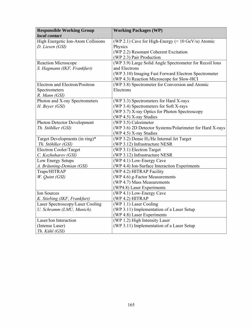
165
Responsible Working Group local contact
Working Packages (WP)
High Energetic Ion-Atom Collisions D. Liesen (GSI)
(WP 2.1) Cave for High-Energy (< 10 GeV/u) Atomic Physics (WP 2.2) Resonant Coherent Excitation (WP 2.3) Pair Production
Reaction Microscope S. Hagmann (IKF, Frankfurt)
(WP 3.9) Large Solid Angle Spectrometer for Recoil Ions and Electrons (WP 3.10) Imaging Fast Forward Electron Spectrometer (WP 4.3) Reaction Microscope for Slow-HCI
Electron and Electron/Positron Spectrometers R. Mann (GSI)
(WP 3.8) Spectrometer for Conversion and Atomic Electrons
Photon and X-ray Spectrometers H. Beyer (GSI)
(WP 3.3) Spectrometers for Hard X-rays (WP 3.4) Spectrometers for Soft X-rays (WP 3.7) X-ray Optics for Photon Spectroscopy (WP 4.5) X-ray Studies
Photon Detector Development Th. Stöhlker (GSI)
(WP 3.5) Calorimeter (WP 3.6) 2D Detector Systems/Polarimeter for Hard X-rays(WP 4.5) X-ray Studies
Target Developments (in ring)* Th. Stöhlker (GSI)
(WP 3.2) Dense H2/He Internal Jet Target (WP 3.12) Infrastructure NESR
Electron Cooler/Target C. Kozhuharov (GSI)
(WP 3.1) Electron Target (WP 3.12) Infrastructure NESR
Low Energy Setups A. Bräuning-Demian (GSI)
(WP 4.1) Low-Energy Cave (WP 4.4) Ion-Surface Interaction Experiments
Traps/HITRAP W. Quint (GSI)
(WP 4.2) HITRAP Facility (WP 4.6) g-Factor Measurements (WP 4.7) Mass Measurements (WP4.8) Laser Experiments
Ion Sources K. Stiebing (IKF, Frankfurt)
(WP 4.1) Low-Energy Cave (WP 4.2) HITRAP
Laser Spectroscopy/Laser Cooling U. Schramm (LMU, Munich).
(WP 1.1) Laser Cooling (WP 3.11) Implementation of a Laser Setup (WP 4.8) Laser Experiments
Laser/Ion Interaction (Intense Laser) Th. Kühl (GSI)
(WP 1.2) High Intensity Laser (WP 3.11) Implementation of a Laser Setup

166
Tables: Resource planning for the individual Working Packages c. Responsibilities and Obligations Related to Laser Experiments SIS100/300 (WP 1.1) Tasks Contributing Groups
Test Experiments (Laser Cooling) at ESR LMU Munich, GSI (AP), Uni Mainz
SIS Lattice Simulations for Interaction Region GSI (SIS), LMU Munich Construction of Deflection Magnets and Vacuum Chambers for Laser Beam Access GSI (SIS), LMU Munich
Beam Dynamics Simulations of Relativistic Laser Cooled Beams LMU Munich, NN Development of Cooling and Spectroscopy Laser System (in Parallel with Test Experiments at ESR) LMU Munich
Planning and Installation of the SIS laser Lab LMU Munich, GSI (AP) Planning and Installation of Laser Beam Line LMU Munich, GSI (AP) Operation LMU Munich,GSI (AP)
Test of X-ray Detectors GSI (AP),LMU Munich, Uni Mainz
X-ray Spectrometer Design and Construction GSI (AP),LMU Munich, Uni Mainz
Operation GSI (AP),LMU Munich
Design and Construction of Few-Cycle Pulse High-Intensity Laser MPQ Munich, LMU Munich, GSI (AP)
d. Schedule and Milestones Related to Laser Experiments SIS100/300 (WP 1.1) Milestones: Milestone Year SIS 100/300 Lattice Simulations for Interaction Region 2005 Construction of Deflection Magnets and Vacuum Chambers for Laser Beam Access 2005
Beam Dynamics Simulations of Relativistic Laser Cooled Beams 2006 Test Experiments (Laser Cooling) at ESR Demonstrating Bandwidth Matching the Initial Momentum Spread 2006
Radiation Damage Test of critical components 2007 Development of Cooling and Spectroscopy Laser System (Based on the Systems Used at the ESR) 2008
X-ray Spectrometer Design and Construction 2008 Installation of the SIS 100/300 Laser Lab 2009 Installation of Laser Beam Line 2009
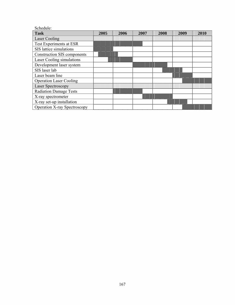
167
Schedule: Task 2005 2006 2007 2008 2009 2010 Laser Cooling Test Experiments at ESR SIS lattice simulations Construction SIS components Laser Cooling simulations Development laser system SIS laser lab Laser beam line Operation Laser Cooling Laser Spectroscopy Radiation Damage Tests X-ray spectrometer X-ray set-up installation Operation X-ray Spectroscopy
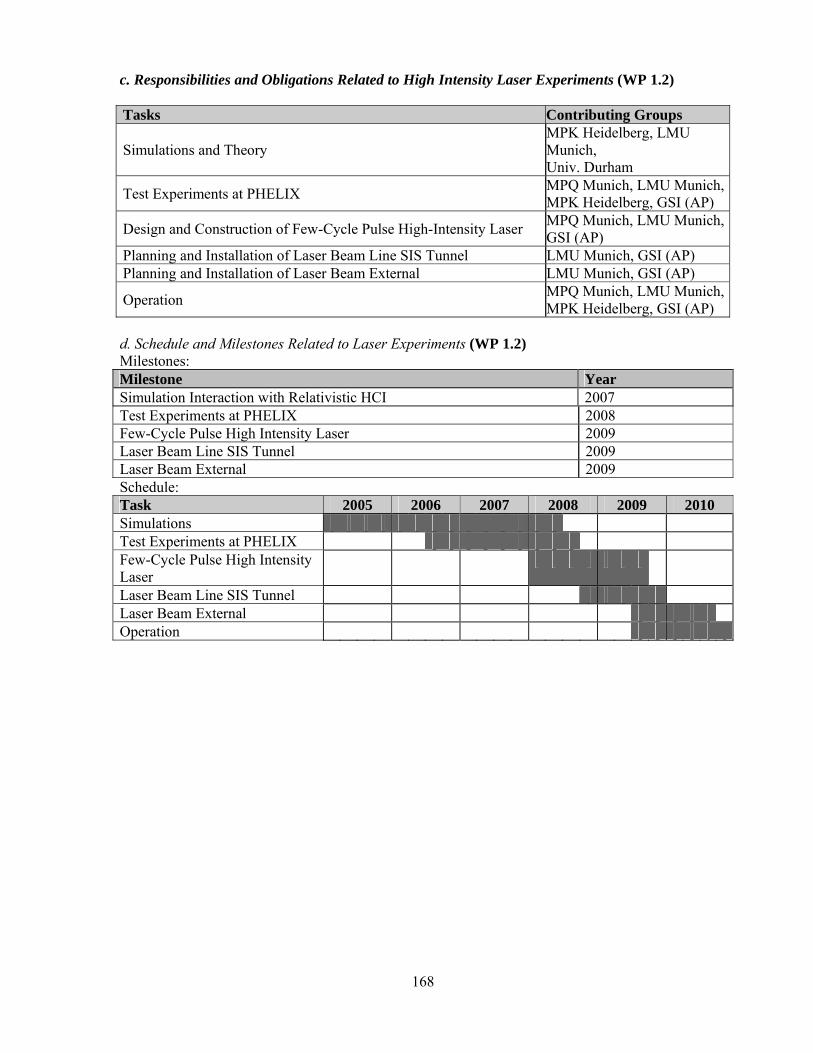
168
c. Responsibilities and Obligations Related to High Intensity Laser Experiments (WP 1.2) Tasks Contributing Groups
Simulations and Theory MPK Heidelberg, LMU Munich, Univ. Durham
Test Experiments at PHELIX MPQ Munich, LMU Munich, MPK Heidelberg, GSI (AP)
Design and Construction of Few-Cycle Pulse High-Intensity Laser MPQ Munich, LMU Munich, GSI (AP)
Planning and Installation of Laser Beam Line SIS Tunnel LMU Munich, GSI (AP) Planning and Installation of Laser Beam External LMU Munich, GSI (AP)
Operation MPQ Munich, LMU Munich, MPK Heidelberg, GSI (AP)
d. Schedule and Milestones Related to Laser Experiments (WP 1.2) Milestones: Milestone Year Simulation Interaction with Relativistic HCI 2007 Test Experiments at PHELIX 2008 Few-Cycle Pulse High Intensity Laser 2009 Laser Beam Line SIS Tunnel 2009 Laser Beam External 2009 Schedule: Task 2005 2006 2007 2008 2009 2010 Simulations Test Experiments at PHELIX Few-Cycle Pulse High Intensity Laser
Laser Beam Line SIS Tunnel Laser Beam External Operation

169
c. Responsibilities and Obligations Related to High-Energy Cave (WP 2.1) Tasks Contributing Groups General Planning of the Cave GSI Ion Optical Simulation GSI, IPN Lyon Installation GSI Commissioning GSI, IPN Lyon, RIKEN d. Schedule and Milestones Related to High-Energy Cave (WP 2.1) Schedule: Task 2005 2006 2007 2008 2009 2010 2011 General Planning of the Cave
Simulations Installations Commissioning A milestone of project magnetic spectrometer will be the planned shut-down of the FRS.

170
c. Responsibilities and Obligations Related to Resonant Coherent Excitation (WP 2.2) Tasks Contributing Groups Design of Goniometer IPN Lyon, RIKEN Ordering and Assembling IPN Lyon, RIKEN Tests in Lyon and RIKEN IPN Lyon, RIKEN Transfer to GSI GSI, IPN Lyon, RIKEN Commissioning GSI, IPN Lyon, RIKEN d. Schedule and Milestones Related to Resonant Coherent Excitation (WP 2.2) Schedule: Task 2005 2006 2007 2008 2009 2010 Design of Goniometer Ordering Components Assenmbling Test in Lyon and RIKEN Transfer to GSI and Settings

171
c. Responsibilities and Obligations Related to Pair Production (WP 2.3) Tasks Contributing Groups Design of Spectrometer GSI, Frankfurt, NN Ordering and Assembling GSI, Stockholm, NN Commissioning GSI, Stockholm, NN d. Schedule and Milestones Related to Pair Production (WP 2.3) Schedule:
Task 2005 2006 2007 2008 2009 2010 Design of Spectrometer Ordering Components Assembling Test Comissioning

172
c. Responsibilities and Obligations Related to Electron Target (WP 3.1) Tasks Contributing Groups General planning and management Cooperation and coordination of external manufacturers and suppliers
GSI
Feasibility of 1A electron current. Expected energy resolution as a function of the electron current Extraction voltage needed for the high electron currents and its influence on the longitudinal electron temperature Reasonable length for the adiabatic acceleration section Strength of the magnetic guiding field with respect to the transversal-longitudinal relaxation Are values for the transverse electron temperature below 3-5 meV attainable without much higher technical effort and complexity? How does the heating of the electron beam in the toroid section depend on the toroid radius? Is a value of 2m for the radius a reasonable one? What is the behavior of the ion beam when the energies of the electron cooler and electron target are very close?
MPI-K Heidelberg
Energy calibration methods Search for suitable low-Z calibration standards. How exact are the known energies? What are the prospects of establishing future calibration standards, which will also include measurements with photons? Search for suitable pairs of heavy and light ions with very similar mass to charge ratios that would allow for a simultaneous injection and storing in the NESR. The light ion has to have known energies. Most likely, both ions will be produced in SFRS. What are the natural line widths of calibration resonances with respect to the required transverse temperature of the electron beam? A breeding scheme of higher charge states by consecutive electron capture is needed, since the ions of interest might be produced at high energies, with no attached electrons.
IAMP Giessen
Residual gas beam profile monitors Reliability of the detector system for the residual gas beam profile monitor Alternative beam monitoring systems.
IMP Lanzhou
Design and Manufacturing of the main components. (Note: The project has been discussed as a topic in the framework of a future cooperation with INP Novosibirsk.)
INP Novosibirsk
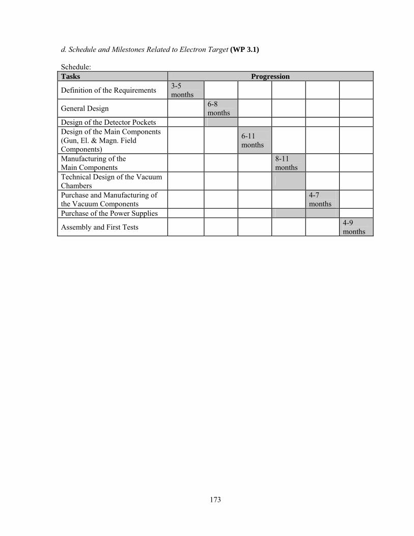
173
d. Schedule and Milestones Related to Electron Target (WP 3.1) Schedule: Tasks Progression
Definition of the Requirements 3-5 months
General Design 6-8 months
Design of the Detector Pockets Design of the Main Components (Gun, El. & Magn. Field Components)
6-11 months
Manufacturing of the Main Components 8-11
months
Technical Design of the Vacuum Chambers
Purchase and Manufacturing of the Vacuum Components 4-7
months
Purchase of the Power Supplies
Assembly and First Tests 4-9 months

174
c. Responsibilities and Obligations Related to Internal Target (WP 3.2) Tasks Contributing Groups performance tests of a modified skimmer geometry at the CELSIUS target TSL, GSI
adaptation of the CELSIUS cooling system to the ESR target TSL, GSI (EXL collaboration)
installation at ESR TSL, GSI (EXL collaboration)
performance test at the ESR TSL, GSI, (EXL collaboration)
design of the new target station for NESR TSL, GSI, FZ-Jülich ordering of new parts, GSI, (EXL collaboration)
assembling of new NESR target and performance test TSL, GSI, (EXL collaboration)
design of target chambers TSL, GSI (EXL collaboration)
installation at NESR TSL, GSI (EXL collaboration)
The Internal Target project for the NESR is a joint activity together with EXL collaboration d. Schedule and Milestones Related to Internal Target (WP 3.2) Milestone Year performance tests of a modified skimmer geometry at the CELSIUS target 7-2006 adaptation of the CELSIUS cooling system to the ESR target 12-2006 results of a feasibility study for a micro-jet target 12-2006 performance test at the ESR finished 07-2007 installation of a micro-jet target at the ESR 07-2007 performance test of a micro-jet target at the ESR finished 01-2008 design of the new target station available 07-2008 design of the NESR support structure available 07-2008 design of target chambers finished 07-2008 assembly of NESR target 2009 first test operation of the NESR target 2009 Task 2005 2006 2007 2008 2009 2010 Skimmer geometry Adaptation to GSI Optimization and tests at ESR Design of target station design of support structure design of target chambers assembly of NESR target first test operation of the NESR target

175
c. Responsibilities and Obligations Related to Spectrometers for Hard X-rays (WP 3.3) Tasks Contributing Groups Assembly GSI Test GSI, AS Kielce Optimization GSI, AS Kielce Alignment Procedure GSI, Uni Fribourg Calibration Procedure GSI, ESRF Grenoble X-ray optical adjustments GSI, Uni Fribourg
Preparation and Test of Curved Transmission Crystals GSI, ESRF Grenoble, Lyon, Uni Jena, CIRIL Caen, Uni Fribourg
d. Schedule and Milestones Related to Spectrometers for Hard X-rays (WP 3.3) Definition of Milestones Milestones Month-Year Completion of Spectrometer Mechanics 07–2004 Characterization of Spectrometer Performance 12–2005 Tuned Apparatus 12–2005 Established Alignment Scheme 04–2006 Established Calibration Scheme 07–2006 Achievement of Adjustments, FOCAL Ready for Transfer 07–2007 Supply of Well Characterized Curved Transmission Crystals 07–2008 Schedule Tasks 2005 2006 2007 2008 Assembly Test Optimization Alignment Procedure Calibration Procedure X-ray Optical Adjustments Preparation and Test of Curved Transmission Crystals
Detector Development, see section
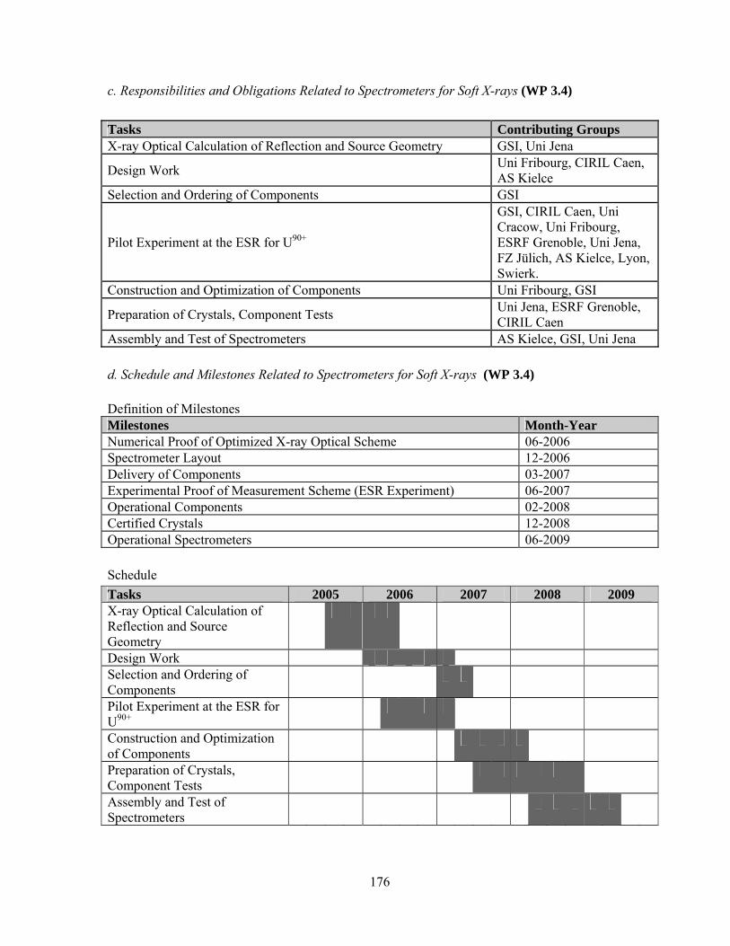
176
c. Responsibilities and Obligations Related to Spectrometers for Soft X-rays (WP 3.4) Tasks Contributing Groups X-ray Optical Calculation of Reflection and Source Geometry GSI, Uni Jena
Design Work Uni Fribourg, CIRIL Caen, AS Kielce
Selection and Ordering of Components GSI
Pilot Experiment at the ESR for U90+
GSI, CIRIL Caen, Uni Cracow, Uni Fribourg, ESRF Grenoble, Uni Jena, FZ Jülich, AS Kielce, Lyon, Swierk.
Construction and Optimization of Components Uni Fribourg, GSI
Preparation of Crystals, Component Tests Uni Jena, ESRF Grenoble, CIRIL Caen
Assembly and Test of Spectrometers AS Kielce, GSI, Uni Jena d. Schedule and Milestones Related to Spectrometers for Soft X-rays (WP 3.4) Definition of Milestones Milestones Month-Year Numerical Proof of Optimized X-ray Optical Scheme 06-2006 Spectrometer Layout 12-2006 Delivery of Components 03-2007 Experimental Proof of Measurement Scheme (ESR Experiment) 06-2007 Operational Components 02-2008 Certified Crystals 12-2008 Operational Spectrometers 06-2009 Schedule Tasks 2005 2006 2007 2008 2009 X-ray Optical Calculation of Reflection and Source Geometry
Design Work Selection and Ordering of Components
Pilot Experiment at the ESR for U90+
Construction and Optimization of Components
Preparation of Crystals, Component Tests
Assembly and Test of Spectrometers

177
c. Responsibilities and Obligations Related to Calorimeter WP(3,5) Working packages for Calorimetric Detector from Cfa (soft X-ray calorimeter) Tasks Contributing Groups Design of 16 channel calorimeter Harvard (Cfa) Transfer and installation at ESR Harvard, Stockholm, GSI Test experiment at ESR Harvard, Stockholm, GSI Design of 100 channel calorimeter Harvard (Cfa) Transfer and installation at ESR Harvard, Stockholm, GSI Test experiment at ESR Harvard, Stockholm, GSI Working packages from Mainz (hard-X-ray calorimeter) Tasks Contributing Groups Design of 32 channel calorimeter Mainz, GSI Transfer and installation at ESR Mainz, GSI Test experiment at ESR Mainz, GSI Design of 96 channel calorimeter Mainz, GSI, Heidelberg Transfer and installation at ESR Mainz, GSI, Heidelberg Test experiment at ESR Mainz, GSI, Heidelberg d. Schedule and Milestones Related to Calorimeter WP(3,5) Definition of Milestones Task (Milestone) Year 16-Pixel calorimeter (Cfa) experiment at ESR (energies soft X-rays up 30 keV) 2005
8-Pixel Lamb shift experiment (Mainz) at ESR (energies soft X-rays up 80 keV)
2006
first test experiment (Cfa) with 100 pixel Array (energies soft X-rays up 30 keV)
2008
first test experiment (Mainz) with 96 pixel Array (energies soft X-rays up 80 keV)
2008
Tasks 2005 2006 2007 2008 16-Pixel calorimeter experiment at ESR (<30 keV)
8-Pixel Lamb shift experiment (Mainz) at ESR (energies soft X-rays up 80 keV)
first test experiment (Cfa) with 100 pixel Array (energies soft X-rays up 30 keV)
first test experiment (Cfa) with 100 pixel Array (energies soft X-rays up 30 keV)
first test experiment (Mainz) with 96 pixel Array (energies soft X-rays up 80 keV)

178
c. Responsibilities and Obligations Related to 2D Detector Systems/Polarimeter WP(3,6)
a) 2D-Germanium-Detector Tasks Contributing Groups
Design Studies for a 2D Micro-Strip Ge(i) Detector GSI, FZ-Jülich. IKF-Frankfurt
Construction of Detector GSI, FZ-Jülich. IKF-Frankfurt
Laboratory Test Experiments GSI, Uni Cracow. Swierk, AS Kielce, IKF-Frankfurt
Adjustment of Electronics to Detector Systems GSI, Uni Cracow. Swierk, AS Kielce, IKF-Frankfurt
Data Acquisition, Data Analysis GSI, Uni Cracow. Swierk
Test Experiments at ESRF and ESR GSI, Uni Cracow. Swierk, AS Kielce, IKF-Frankfurt
b) Polarimeter for hard X-rays
Tasks Contributing Groups
Design Studies for a Polarimeter-Ge(i) Detector GSI, FZ-Jülich. IKF-Frankfurt
Construction of Detector GSI, FZ-Jülich. IKF-Frankfurt
Laboratory Test Experiments GSI, Uni Cracow. Swierk, AS Kielce, IKF-Frankfurt
Design and Construction of Chip Read Out Electronics/DSP-Board GSI, Uni Cracow. Swierk Test of prototyp electronics GSI, Uni Cracow. Swierk
Adjustment of Electronics to Detector Systems GSI, Uni Cracow. Swierk, AS Kielce, IKF-Frankfurt
Data Acquisition, Data Analysis GSI, Uni Cracow. Swierk
Test Experiments at ESRF and ESR GSI, Uni Cracow. Swierk, AS Kielce, IKF-Frankfurt
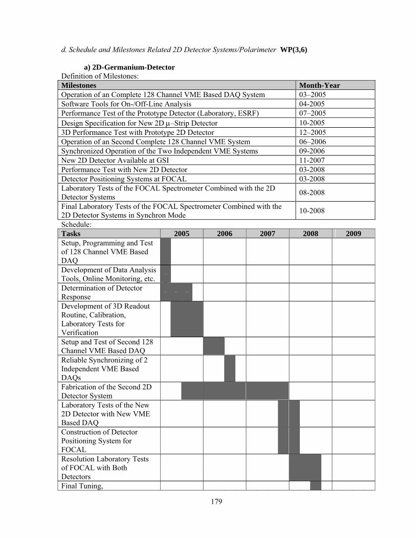
179
d. Schedule and Milestones Related 2D Detector Systems/Polarimeter WP(3,6) a) 2D-Germanium-Detector Definition of Milestones: Milestones Month-Year Operation of an Complete 128 Channel VME Based DAQ System 03–2005 Software Tools for On-/Off-Line Analysis 04-2005 Performance Test of the Prototype Detector (Laboratory, ESRF) 07–2005 Design Specification for New 2D µ–Strip Detector 10-2005 3D Performance Test with Prototype 2D Detector 12–2005 Operation of an Second Complete 128 Channel VME System 06–2006 Synchronized Operation of the Two Independent VME Systems 09-2006 New 2D Detector Available at GSI 11-2007 Performance Test with New 2D Detector 03-2008 Detector Positioning Systems at FOCAL 03-2008 Laboratory Tests of the FOCAL Spectrometer Combined with the 2D Detector Systems 08-2008
Final Laboratory Tests of the FOCAL Spectrometer Combined with the 2D Detector Systems in Synchron Mode 10-2008
Schedule: Tasks 2005 2006 2007 2008 2009 Setup, Programming and Test of 128 Channel VME Based DAQ
Development of Data Analysis Tools, Online Monitoring, etc.
Determination of Detector Response
Development of 3D Readout Routine, Calibration, Laboratory Tests for Verification
Setup and Test of Second 128 Channel VME Based DAQ
Reliable Synchronizing of 2 Independent VME Based DAQs
Fabrication of the Second 2D Detector System
Laboratory Tests of the New 2D Detector with New VME Based DAQ
Construction of Detector Positioning System for FOCAL
Resolution Laboratory Tests of FOCAL with Both Detectors
Final Tuning,

180
b) Polarimeter for Hard X-rays Definition of Milestones: Milestones Month-Year Design Specification for Telescope 07–2005 Software Tools for On-/Offline Analysis 01-2007 Compton Telescope Available at GSI 07–2006 Performance Test Using a Standard VME Based DAQ System 10-2006 128 Channel DSP Based Readout System 06–2006 DSP System Adapted to Telescope 12-2006 Software Tools for On-/Offline Analysis 01-2007 Analysis Algorithms and Interface to GSI DAQ 02-2007 Performance Test with Telescope 04-2007 Test Experiments at ESRF and ESR 06-2007 Schedule: Tasks 2005 2006 2007 2008 2009 Calculation and Simulation of Detector Parameters for Polarized Photon Detection
Preparing Data Analysis Environment, Online Monitoring, etc.
Construction and Fabrication of the Telescope
Design, Prototyping and Fabrication of DSP Electronics
Adaptation of the Available VME Electronic to the Compton Telescope
Developing Analysis Algorithms for DSP Electronics and Software Interface to GSI DAQ Environment
Laboratory Tests of Detector Setup with DSP Electronics with Respect to Resolution, Event Reconstruction, Efficiency,
Final Preparation and Performance Tests for Beamtime Experiments

181
c. Responsibilities and Obligations Related to X-ray Optics WP(3,7) Tasks Sub Tasks Contributing Groups
Development Manufacturing Polycapillary X-ray Focusing
Optics (C) at the Gas Target Operation
AS Kielce
Development Manufacturing Multilayer X-ray Focusing Lens
(MXFL) at the Gas Target Operation
Havard CfA, Camebridge, USA
Development Manufacturing
Total Reflection Cylindrical Mirror (TRCM) at the Electron Target Operation
AS Kielce
d. Schedule and Milestones Related to X-ray Optics WP(3,7) Definition of Milestones: Milestones Month-Year Completion of Detailed Simulations, Optimized Geometry 07–2006 Parts Ordered 12–2006 Test Setup Completed 03–2007 Results from Tests Analyzed 12–2007 Systems Installed 07–2008 Commissioning Complete 12–2008 Schedule: Tasks 2005 2006 2007 2008 Detailed Simulation Fix Parameters, Order Parts Assembly of Testbench Measurements on Testbench Installation Commissioning

182
c. Responsibilities and Obligations Related to Electron Spectrometer WP(3,8) Tasks Contributing Groups
Design Studies Uni of Creete Heraklion, CSIC Madrid
Construction of Transport Magnet and Chamber IMP-Lanzhou, GSI, Atomki Debrecen
Purchase of Detectors, Power Supplies, Controlling Electronics and Parts, Mounting and Testing at Laboratory
GSI, Atomki Debrecen, MPI-K Heidelberg
Design and Construction of High-Resolution Spectrometer (HRS), Ordering Parts, Chamber, Valve and Electronics
GSI, Atomki Debrecen, MPI-K Heidelberg,IKF Frankfurt
Mounting and Test HRS GSI, Atomki Debrecen, MPI-K Heidelberg, IKF Frankfurt, Uni Stockholm
d. Schedule and Milestones Related to Electron Spectrometer WP(3,8) Schedule Task Year Design Studies until 2006 Construction of Transport Magnet and Chamber end 2006 Purchase of Detectors, Power Supplies, Controlling Electronics and Parts, Mounting and Testing at Laboratory
2007
Design and Construction of High Resolution Spectrometer (HRS), Ordering Parts, Chamber, Valve and Electronics
2007 / 2008
Mounting and Test HRS 2008 /.2009 Ready to Operate 2009

183
c. Responsibilities and Obligations Related to Extended Reaction Microscope WP(3,9)
d. Schedule and Milestones Related to Extended Reaction Microscope WP(3,9) Schedule: Task Year Electron/Recoil Ion Optical Calculations 2005 - 2006 Model Solenoid configuration in Target Zone 2005 - 2006 Manufacturing /Testing Small Prototype Configs. ( UNILAC) 2005 - 2006 2D Position Sensitive Detectors for Electrons (meV to KeV) 2005 - 2006 Technical Design for Toroid-Coils and Lenses 2006 - 2007 Purchase, Construction, Commissioning 2008 - 2009 Vacuum Chamber, Design-Manufacturing 2008 - 2009 Manufacturing/ Ordering of Toroid-Coils, Solenoid Lenses etc 2008 - 2009 Vacuum System Configuration, Purchase 2008 - 2009 Orders of Power Supplies for Coils, Solenoid 2008 - 2009 Electronics/Interface and Adaptation to Storage Ring-Beam Lattice 2008 - 2009 Assembly of Spectrometer + Tests 2008 - 2009
Tasks Contributing Groups Recoil- and Low Energy Electron Spectrometer: Electro-Optical Calculations-Solenoid Electro-Optical Calculations –Extraction Zone Prototype Testing Multihit-Capable 2D-Position Sensitive Detectors for Low-Energy Electrons 2D-Position Sensitive Detectors for Recoil Ions Engineering Design for UHV-Vacuum Chamber Procurement
MPI-K, Heidelberg, IKF Frankfurt, JRM - Kansas State,West.Mich. State /Kalamazoo, Uni of Missouri/Rolla, Hash. U. of Jordan, IMP Lanzhou, Fudan Univ, CSIC Madrid, Atomki Debrecen,Uni of Crete, CCF Mexico

184
c. Responsibilities and Obligations Related to Imaging Forward Spectrometer WP(3,10) Tasks Contributing Groups 0° Imaging Forward Electron Spectrometer: Electro-Optical Calculations 2D Position Sensitive Detector Engineering Design Procurement
IKF Frankfurt, GANIL Caen, Uni of Catania, Uni of Missouri/Rolla, Uni of Crete
d. Schedule and Milestones Related to Imaging Forward Electron Spectrometer WP(3,10) Task Year Electron/Recoil Ion Optical Calculations 2005 - 2006 Technical Design for Dipoles, and Triplett - Lenses 2006 - 2007 2D Position Sensitive Detectors (100 keV to MeV) 2006 - 2007 Configuration of Moveable Calibration Sources 2006 - 2007 Vacuum Chamber, Design-Manufacturing 2008 - 2009 Manufacturing/ Ordering of Dipoles, 2008 - 2009 Vacuum System Configuration, Purchase 2008 - 2009 Orders of Power Supplies for Dipoles and Tripletts 2008 - 2009 Electronics/Interface and Adaptation to Storage Ring-Beam Lattice 2008 - 2009 Assembly of Spectrometer + Tests 2008 - 2009

185
c. Responsibilities and Obligations Related to Laser Experiments WP(3,11) Task Contributing Groups
Optical Laser Spectroscopy and Test of Relativity Definition of the Specifications for the Excitation and Detection Region Uni Mainz, GSI
Specifications for the ESR Laser Laboratory Uni Paris Sud, MBI Radiation and Laser Safety GSI Design and Construction of a Detection System for Photons in the Optical Regime Uni Mainz
Laser Beamline and Laboratory for NESR GSI, Uni Paris Sud Installation of the Detection System GSI, Uni Mainz Design of a Laser System for Optical Spectroscopy Uni Mainz, GSI Installation of the Laser System Uni Main, GSI
X-ray Laser Spectroscopy Development of an X-ray Laser MBI, Uni Paris Sud Test Experiments at the Reinjection Beam Line MBI, GSI, Uni Paris Sud Installation of a Photon Detection System MBI, GSI, Uni Paris Sud Definition of Requirements (R&D) LLNL, LBL, GSI Safety Requirements (R&D) GSI, TUD Lasersystem with High Rep. Rate MBI, GSI Laser Beam Line GSI, MBI Detection System for High Energy Photons GSI, FZ-Jülich Installation of Components GSI, MBI, LLNL
Ultra-High laser Fields Design Studies for Laser, Electron Beam, Detector (R&D) TUD, LLNL, LBL, GSI Test-experiments at the ESR Jet-Target (R&D) Uni Stockholm, GSI Design of Laser Laboratory GSI, LLNL
Installation of Laser System Uni Mainz, LMU Munich, GSI
Photon Detection (R&D) Uni Frankfurt Laser Beam Line GSI, LMU Munich Installation GSI, LMU Munich Installation of Components Uni Mainz, GSI d. Schedule and Milestones Related to Laser Experiments (WP 3.11) a) Optical Laser Spectroscopy Schedule: Task Year Definition of the Specifications for the Excitation and Detection Region 2004 -2005 Specifications for the ESR Laser Laboratory 2005 Radiation and Laser Safety 2006 Design and Construction of a Detection System for Photons in the Optical Regime
2006 – 2007
Laser Beamline and Laboratory for NESR 2007 – 2008 Installation of the Detection System 2008 – 2009 Design of a Laser System for Optical Spectroscopy 2007 – 2009 Installation of the Laser System and Components 2009
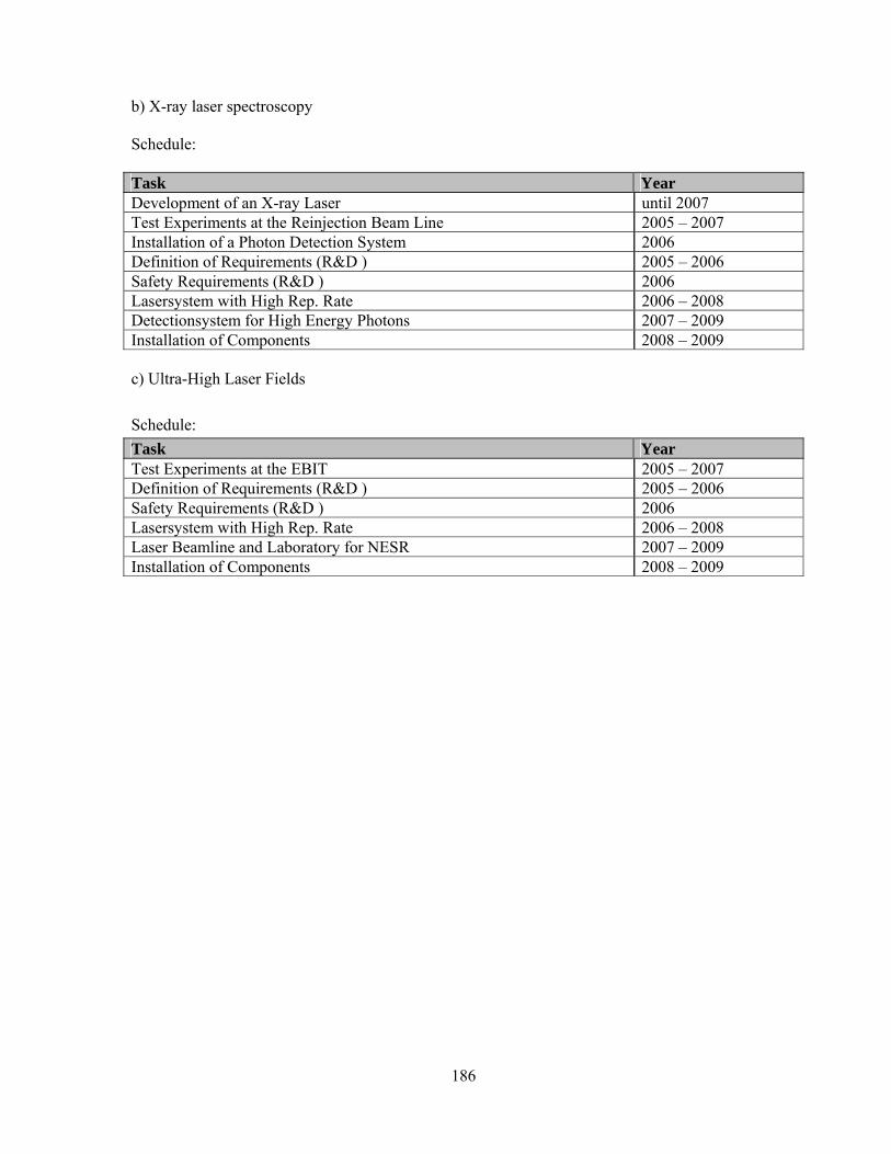
186
b) X-ray laser spectroscopy Schedule: Task Year Development of an X-ray Laser until 2007 Test Experiments at the Reinjection Beam Line 2005 – 2007 Installation of a Photon Detection System 2006 Definition of Requirements (R&D ) 2005 – 2006 Safety Requirements (R&D ) 2006 Lasersystem with High Rep. Rate 2006 – 2008 Detectionsystem for High Energy Photons 2007 – 2009 Installation of Components 2008 – 2009 c) Ultra-High Laser Fields Schedule: Task Year Test Experiments at the EBIT 2005 – 2007 Definition of Requirements (R&D ) 2005 – 2006 Safety Requirements (R&D ) 2006 Lasersystem with High Rep. Rate 2006 – 2008 Laser Beamline and Laboratory for NESR 2007 – 2009 Installation of Components 2008 – 2009

187
c.. Responsibilities and Obligations Infrastructure and Maintenance WP(3,12) The task related to Infrastructure and Maintenance will be shared between the electron target and internal target working groups

188
c. Responsibilities and Obligations Related to Low-Energy Cave (WP 4.1)
Tasks Contributing Groups Magnetic spectrometer
Design of the Magnetic Spectrometer GSI, JINR Dubna, INP Lyon
Spectrometer Construction GSI, IMP Lanzhou
Installation and Commissioning GSI, Uni. Giessen, IMP Lanzhou
The Focal plane detector
Design of the Focal Plane Detector GSI, Uni. Giessen, INP Lyon
Prototype Building and Testing GSI, Hashemite Uni. Amman, NIPNE Bucharest
Final Detector Cconstruction GSI, NIPNE Bucharest
Testing and Commissioning GSI, NIPNE Bucharest, Hashemite Uni. Zarqa
Diagnosis Detector Prototype Based on the R&D for the Focal Plane Detector GSI, NIPNE Bucharest
The Cave Design and Planning GSI Acquisition of the Components and Construction GSI
Commissioning GSI, NIPNE Bucharest, Uni Giessen , Hashemite Uni Amman, INP Lyon
For commissioning of this area and of all experiments which will be performed here, it is aimed to install a highly charged ion source as injector into the LSR (see section B4, LSR). The task of coordinating and planning the acquisition of such a source will be performed by the interested groups and the CRYRING team from Stockholm in collaboration with GSI, under the leading of K. Stiebing from Frankfurt University (see working groups).

189
d. Schedule and Milestones Related to Low-Energy Cave (WP 4.1) a) Spectrometer for Ion Beams (3-130 MeV/u), Charge and Momentum Selective Schedule: Task Year Physics Requirements: Definition of the Design Parameters 2004- 2005 Ion-Optical Simulations 2005-2006 Purchasing of the Magnet and Associated Infrastructure 2007-2008 Mounting and Commissioning of the Spectrometer in the Existing Cave A 2009 Installation of the Spectrometer at the Final Location 2010-2011 b) 2D Focal Plane Detector Schedule: Task Year Tests of Different Read-Out Methods for a 2D Diamond Detector 2004-2005 Design of the 2D-Detector for the Focal Plane 2006 Construction and Testing of a Prototype 2006-2008 Construction of the Final Detector and the Associated Electronics 2008-2010 c) Beam Lines Schedule: Task Year Final Design of the NESR - Low Energy Cave and LSR- Low-Energy Cave Beam Line 2008
Civil Construction 2006-2010 Mounting and Commissioning of the LSR- Low-Energy Cave Beam Line 2010-2011 Mounting and Commissioning of the NESR – Low-energy Cave Beam Line 2010-2011
d) Beam Diagnostic for Slow Heavy Ions Schedule: Task Year Feasibility Studies 2007 Construction and Testing of a Prototype Detector 2009 Design and Construction of the Beam Diagnostics 2009-2011 Definition of Milestones: Milestone Year Definition of the Final Parameters of the Magnetic Spectrometer End of 2005 Final Decision About the Read-Out Method for the 2D Focal Plane Detector Beginning 2006
Final Decision About the Design of the Beam Diagnosis Detector 2008 Test of the Detector's Associated Read-out Electronics Completion 2009 Completion of the Spectrometer Mounting 2009 Resuming the 'in-beam' performance test of the focal plane detector and associated electronics 2010
Completion of the LSR-Cave Beam Line 2011
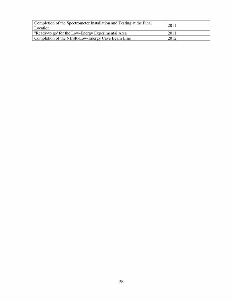
190
Completion of the Spectrometer Installation and Testing at the Final Location 2011
''Ready-to go' for the Low-Energy Experimental Area 2011 Completion of the NESR-Low-Energy Cave Beam Line 2012

191
c. Responsibilities and Obligations Related to HITRAP (WP 4.2) Tasks HITRAP Facility Contributing Groups Second-Harmonic Buncher before IH-Structure, Including RF Sender at 216 MHz Uni Frankfurt, GSI
Transport of HITRAP Facility from ESR to NESR GSI Transport of HITRAP Experiments from ESR to FLAIR Building Ext. Collaborators
New Beam Diagnostic Tools According to New FAIR Standards GSI
Safety: Detection Devices for Antiprotons GSI Incorporation of HITRAP Slow Control System into the New Accelerator Control and Timimg System GSI
Beamlines to Antiproton Experiments GSI, Ext. Collaborators Commissioning with LSR/NESR Beams GSI, Uni Frankfurt, Univ Mainz d. Schedule and Milestones Related to HITRAP (WP 4.2) Definition of Milestones Milestones Month-Year Transport of HITRAP Experiments from ESR to FLAIR Building 2011 Commissioning with LSR/NESR Beams 2011/12 Schedule: Task 2010 2011 2012 Transport of HITRAP Facility from ESR to NESR
Transport of HITRAP Experiments from ESR to FLAIR Building
New Beam Diagnostic Tools According to New FAIR Standards
Safety: Detection Devices for Antiprotons Incorporation of HITRAP Slow Control System into the New Accelerator Control and Timing System
Beam Lines to Antiproton Experiments Commissioning with LSR/NESR Beams

192
c. Responsibilities and Obligations Related to Reaction Microscope (WP 4.3) Tasks Contributing Groups Recoil- and Low Energy Electron Spectrometer Electron-and Ion Optics Electrostatic Field("Barrel") Electrode Design 2D Position Sensitive Detectors Vacuum Configuration Supersonic-Jet
IKF Frankfurt, JRM - Kansas State Univ., MPI-K Heidelberg, West.Mich. State/Kalamazoo, USA CSIC Madrid, Atomki Debrecen, Fudan Univ,Uni of Crete
d. Schedule and Milestones Related to Reaction Microscope (WP 4.3) Schedule: Task Year Adaptation of Vacuum System of MPI-K Reaction Microscope To LSR UHV-conditions
2006 - 2007
Technical Design for Hg-Supersonic Jet-Oven 2006 - 2007 Manufacturing of Hg Jet 2007 - 2008 Test of Supersonic Hg jet with Reaction Microscope at UNILAC 2008 - 2009 Electronics/Interface and Adaptation to Storage Ring-Beam Lattice 2008 - 2009 Assembly of Spectrometer + Tests at LSR 2009

193
c. Responsibilities and Obligations Related to Ion-Surface Interaction Studies (WP 4.4) Tasks Ion-surface studies Contributing Groups
Design and Construction of Energy Filter, TOF and Detector
KVI Groningen, IP JU Krakow, Uni Stockholm, TU. Vienna, St. Petersburg
Simulation of Detector St. Petersburg, TU Vienna Design and Construction of Recipient and Preparation KVI Groningen, IP JU Krakow,
Uni Stockholm
Assembling & Testing KVI Groningen, IP JU Krakow, Uni Stockholm
Ion Beam Simulations TU. Vienna Complete Check of Experiments KVI Groningen, IP JU Krakow,
Uni Stockholm Installation at HITRAP KVI Groningen, IP JU Krakow,
Uni Stockholm, GSI d. Schedule and Milestones Related to Ion-Surface Interaction (WP 4.4) Schedule Tasks 2005 2006 2007 2008 Design of Energy Filter Design of TOF Design of Yield Detector Simulation of Detector Construction Energy Filter Construction TOF Construction Yield Detector Design Recipient Design Transfer & Preparation Construction Recipient Construction Preparation Assembling & Testing Calibration Detectors Ion Beam Simulations Interface Construction Complete Check Experiments Installation at HITRAP
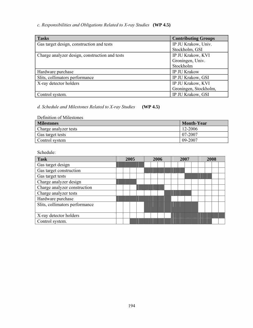
194
c. Responsibilities and Obligations Related to X-ray Studies (WP 4.5) Tasks Contributing Groups Gas target design, construction and tests IP JU Krakow, Univ.
Stockholm, GSI Charge analyzer design, construction and tests IP JU Krakow, KVI
Groningen, Univ. Stockholm
Hardware purchase IP JU Krakow Slits, collimators performance IP JU Krakow, GSI X-ray detector holders IP JU Krakow, KVI
Groningen, Stockholm, Control system. IP JU Krakow, GSI d. Schedule and Milestones Related to X-ray Studies (WP 4.5) Definition of Milestones Milestones Month-Year Charge analyzer tests 12-2006 Gas target tests 07-2007 Control system 09-2007 Schedule: Task 2005 2006 2007 2008 Gas target design Gas target construction Gas target tests Charge analyzer design Charge analyzer construction Charge analyzer tests Hardware purchase Slits, collimators performance
X-ray detector holders Control system.

195
c. Responsibilities and Obligations Related to g-Factor Measurements (WP 4.6) Tasks Contributing Groups Design and Specification of the Trap System Uni Mainz, GSI Design of the Detection Electronics Uni Mainz, Uni Greifswald Computer Control and Data Acquisition System Uni Mainz, Uni Greifswald Assembly and Tests of the Trap System Uni Mainz, GSI Off-Line Test Measurements with Light HCI Uni Mainz, GSI
Commissioning of Trap System at HITRAP/ESR Uni Mainz, Uni Greifswald, GSI
Test Experiments at ESR Uni Mainz, Uni Greifswald, GSI
e. Schedule and Milestones Related to g-Factor Measurements (WP 4.6) Milestones Month-Year Definition of Trap Specifications 08-2005 Trap Machining 09-2006 Trap Installation and Tests 12-2007 g-Factor Measurements 02-2009 Schedule: Tasks 2005 2006 2007 2008 2009 Definition of Trap Specifications
Trap Simulation and Design Trap Machining Trap Completion Design of Detection Electronics
Design of Beam Injection Control System Beam Transport Simulation/Calc.
Beam Line Machining Beam Line Installation Electronics Installation and Tests
Trap Installation and Tests Commissioning at HITRAP g-Factor Measurements

196
c. Responsibilities and Obligations Related to Mass Measurements (WP 4.7) Tasks Contributing Groups Simulation of Injection/Ejection and Definition of SuMa Specifications
GSI, Uni Mainz, Uni Greifswald
SuMa Installation and Alignment at Mainz Uni Mainz, Uni Greifswald
Trap Simulation and Design GSI, Uni Mainz, Uni Greifswald
Trap Machining Uni Mainz, Uni Greifswald Trap Installation at Mainz Uni Mainz, Uni Greifswald Design and Construction of Detector System and Calibration with Ion Source
GSI, Uni Mainz, Uni Greifswald
Ion Optical Design of Injection/Ejection Line, Beam Transport Simulation/Calc.
GSI, Uni Mainz, Uni Greifswald
Control System Development GSI
Beam Line Machining GSI, Uni Mainz, Uni Greifswald
Installation of Trap and Detector System at GSI GSI, Uni Mainz, Uni Greifswald
Beam Line Installation and Alignment GSI, Uni Mainz, Uni Greifswald
Commissioning Tests with Off-Line Ion Sources GSI, Uni Mainz, Uni Greifswald
Accuracy Check, Test Experiment GSI, Uni Mainz, Uni Greifswald
Experimental Program GSI, Uni Mainz, Uni Greifswald
d. Schedule and Milestones Related to Mass Measurements (WP 4.7) Schedule: Tasks / Milestones 2005 2006 2007 2008 2009 Define SuMa Specifications Oder/Delivery SuMa SuMa Installation at Mainz Trap Simulation and Design Trap Machining Trap Completion at Mainz Detector / Ion Source Construction
Design Injection/Ejection Line Control System Development Beam Transport Simulation/Calc.
Beam Line Machining Beam Line Installation Detector Installation and Tests Trap Installation and Tests at GSI
Accuracy Check Off-line Mass Measurements On-line Mass Measurements

197
c. Responsibilities and Obligations Related to Laser Measurements (WP 4.8) Tasks Contributing Groups Definition of Magnet Requirements GSI, IC London Identification Spectral Lines GSI, IC London Purchase Suitable Lasers IC London Calculation of Trap Parameters, Design Trap GSI, IC London Construction of Trap IC London Tests of Trap in London IC London Installation of Equipment at GSI GSI, IC London Interface with Ion Beam GSI, IC London Initial Tests GSI, IC London Commissioning with Off-Line sources, Optimization GSI, IC London Experiments GSI, IC London d. Schedule and Milestones Related to Mass Measurements (WP 4.8) Schedule: Tasks / Milestones 2005 2006 2007 2008 2009 Definition of Magnet Requirements
Purchase of Magnets Identification of Spectral Lines
Purchase of Suitable Lasers Design Trap Calculation of Trap Parameters
Construction of Trap Tests of Trap in London Transport of Setup to GSI Installation of Eequipment Interface to Ion Beam Initial Tests Optimization Off-Line Test Experiments On-Line Test Experiments
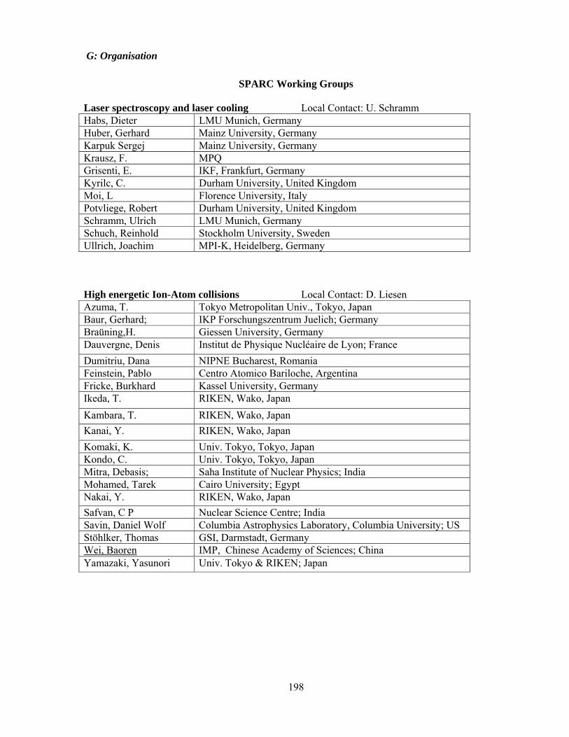
198
G: Organisation
SPARC Working Groups
Laser spectroscopy and laser cooling Local Contact: U. Schramm Habs, Dieter LMU Munich, Germany Huber, Gerhard Mainz University, Germany Karpuk Sergej Mainz University, Germany Krausz, F. MPQ Grisenti, E. IKF, Frankfurt, Germany Kyrilc, C. Durham University, United Kingdom Moi, L Florence University, Italy Potvliege, Robert Durham University, United Kingdom Schramm, Ulrich LMU Munich, Germany Schuch, Reinhold Stockholm University, Sweden Ullrich, Joachim MPI-K, Heidelberg, Germany High energetic Ion-Atom collisions Local Contact: D. Liesen Azuma, T. Tokyo Metropolitan Univ., Tokyo, Japan Baur, Gerhard; IKP Forschungszentrum Juelich; Germany Braüning,H. Giessen University, Germany Dauvergne, Denis Institut de Physique Nucléaire de Lyon; France Dumitriu, Dana NIPNE Bucharest, Romania Feinstein, Pablo Centro Atomico Bariloche, Argentina Fricke, Burkhard Kassel University, Germany Ikeda, T. RIKEN, Wako, Japan Kambara, T. RIKEN, Wako, Japan Kanai, Y. RIKEN, Wako, Japan Komaki, K. Univ. Tokyo, Tokyo, Japan Kondo, C. Univ. Tokyo, Tokyo, Japan Mitra, Debasis; Saha Institute of Nuclear Physics; India Mohamed, Tarek Cairo University; Egypt Nakai, Y. RIKEN, Wako, Japan Safvan, C P Nuclear Science Centre; India Savin, Daniel Wolf Columbia Astrophysics Laboratory, Columbia University; US Stöhlker, Thomas GSI, Darmstadt, Germany Wei, Baoren IMP, Chinese Academy of Sciences; China Yamazaki, Yasunori Univ. Tokyo & RIKEN; Japan

199
Working Group: Electron target Local Contact: C. Kozhuharov Beller, Peter GSI, Darmstadt, Germany Böhm, Sebastian Giessen University, Germany Brandau, Carsten GSI, Darmstadt, Germany Currell, Fred Queen's University, Belfast, Northern Ireland Danared, Håkan Manne Siegbahn Laboratory, Stockholm, Sweden Koop, Ivan Budker Institute, Novosibirsk, Russia Kozhuharov, Christophor GSI, Darmstadt, Germany Lestinsky, Michael Max-Planck-Institut für Kernphysik, Heidelberg, Germany Ma,Xinwen Institute of Modern Physics, Lanzhou, China, Müller, Alfred Giessen University, Germany N.N. ; Queen's University, Belfast, Northern Ireland N.N.: Instytut Fizyki Jądrowej, Cracow, Poland N.N.; Stockholm University, Sweden N.N.; Institute of Modern Physics, Lanzhou, China, Parkhomchuk, Vasily Budker Institute, Novosibirsk, Russia Schippers, Stefan Giessen University, Germany Schmidt, Eike Giessen University, Germany Schuch, Reinhold Stockholm University, Sweden Shatunov, Yury Budker Institute, Novosibirsk, Russia Skeppstedt, Örjan Manne Siegbahn Laboratory, Stockholm, Sweden Skrinsky, Alexander Budker Institute, Novosibirsk, Russia Sprenger, Frank Max-Planck-Institut für Kernphysik, Heidelberg, Germany Stachura, Zbigniew Instytut Fizyki Jądrowej, Cracow, Poland Steck, Markus GSI, Darmstadt, Germany Wolf, Andreas Max-Planck-Institut für Kernphysik, Heidelberg, Germany Target developments (in ring) Local contact: Th. Stöhlker Bureyeva, Lyudmila ISR, Moscow, Russia Currell, Fred Queen's University, Belfast; United Kingdom Egelhof, Peter GSI, Darmstadt, Germany Ekström, C. Uppsala, Sweden Jakobsson, B. Lund, Sweden Ma, Xinwen Institute of Modern Physics, Lanzhou, China, Popp, Ulrich GSI Darmstadt Germany Rathmann, Frank Institut fuer Kernphysik, Germany Savin, Daniel Wolf Columbia Astrophysics Laboratory, Columbia University; US Stöhlker, Thomas GSI, Darmstadt, Germany

200
Working Group: Electron Spectroscopy Local Contact: R. Mann Mann, Rido GSI, Darmstadt, Germany Garcia, Gustavo CSIC, Madrid, Spain Ma,Xinwen Institute of Modern Physics, Lanzhou, China, Moshammer, Robert MPI-K, Heidelberg, Germany Schuch, Reinhold Stockholm University, Sweden Stiebing, Kurt Ernst IKF, Frankfurt University, Germany Stöhlker, Thomas GSI, Darmstadt; IKF, Frankfurt University, Germany Sulik, Bela Debrecen Atomki, Hungary Ullrich, Joachim MPI-K, Heidelberg, Germany Zouros, Theo J.M. University of Crete and IESL-FORTH; Greece Working Group: Photon and X-ray spectrometers Local contact: H. Beyer Banas, Dariusz SA Kielce, Poland Beyer, Heinrich GSI, Darmstadt, Germany Dörner, Reinhard IKF, Frankfurt University, Germany Dousse, Jean-Claude Fribourg University, Switzerland Fleischmann, Andreas Kirchhoff-Institut, Heidelberg University, Germany Foerster, Eckhart University of Jena, Germany Gumberidze, Alexandre GSI, Darmstadt, Germany Krings, Thomas FZ-Jülich, Germany Manil, Bruno CIRIL-GANIL, Caen, France Pajek, Marek SA Kielce, Poland Protic, Davor FZ-Jülich, Germany Samek, Stefan Cracow University, Poland Sierpowski, Dominik Cracow University, Poland Silver, Eric Harward-Smithsonian University, USA Simionovici, Alexandre Ecole Normale Superieure de Lyon, France Stachura, Zbigniew INP, Cracow, Poland Stöhlker, Thomas GSI, Darmstadt, Germany Szlachetko, Jakub Fribourg, University Tashenov, Stanislav GSI, Darmstadt, Germany Warczak, Andrzej Cracow University, Poland Wehrhan, Ortrud University of Jena, Germany Weick, Helmut GSI, Darmstadt, Germany

201
Working Group: Photon detector development Local contact: Th. Stöhlker Banas, Dariusz SA Kielce, Poland Beyer, Heinrich GSI, Darmstadt, Germany Currell, Fred Queen's University, Belfast; United Kingdom Dörner, Reinhard IKF, Frankfurt University, Germany Dousse, Jean-Claude Fribourg University, Switzerland Enss, Christian Heidelberg University, Germany Egelhof, Peter GSI, Darmstadt Fleischmann, Andreas Kirchhoff-Institut, Heidelberg University, Germany Gumberidze, Alexandre GSI, Darmstadt, Germany Kajetanowicz, Marcin Cracow University, Poland Krings, Thomas FZ-Jülich, Germany Ma, Xinwen IMP Lanzhou, China Pajek, Marek SA Kielce, Poland Protic, Davor FZ-Jülich, Germany Samek, Stefan Cracow University, Poland Samek, Stefan Jagiellonian University Institute of Physics; Poland Savin, Daniel Wolf Columbia Astrophysics Laboratory, Columbia University; US Sierpowski, Dominik Cracow University, Poland Silver, Eric Harward-Smithsonian University, USA Stachura, Zbigniew INP, Cracow, Poland Stöhlker, Thomas GSI, Darmstadt, Germany Szlachetko, Jakub Fribourg, University Tashenov, Stanislav GSI, Darmstadt, Germany Warczak, Andrzej Cracow University, Poland Weick, Helmut GSI, Darmstadt, Germany Zou, Yaming Fudan University, Shanghai, China Working Group: Laser/Ion interaction (intense laser) Local contact: Th. Kühl Gwinner, Gerald University of Manitoba; Canada Huber, Gerhard Mainz University, Germany Karpuk Sergej Mainz University, Germany Keitel, Christoph H MPI-K, Heidelberg, Germany Klisnick, A. LIXAM Univ. Paris-Sud, France Kyrilc, C. Durham University, United Kingdom Moshammer, Robert MPI-K, Heidelberg, Germany Nickles, P. Max-Born-Institute Berlin, Germany Potvliege, Robert Durham University, United Kingdom Reinhold Schuch Stockholm University, Sweden Ross, D LIXAM Univ. Paris-Sud, France Sandner, W. Max-Born-Institute Berlin, Germany Schneider, Dieter LLNL, US Ullrich, Joachim MPI-K, Heidelberg, Germany Zielbauer, B. Max-Born-Institute Berlin, Germany

202
Working Group: Reaction Microscope Local contact: S. Hagmann Ali, Rami Hash. Univ. of Jordan Cisneros, Carmen CCF Universidad Nacional Autónoma de México Dörner Reinhard Inst. f. Kernphysik, Univ. Frankfurt, Germany Dubois, Robert Univ.of Missouri, Rolla, USA Garcia, Gustavo CSIC/ Madrid, Spain Hagmann, Siegbert Inst. f. Kernphysik, Univ. Frankfurt, Germany Kamber, Emanuel JRM - Kansas State University, USA Lanzano, Gaetano University of Catania, Italy Ma, Xinwen Inst. Mod. Phys., Lanzhou, China Moshammer, Robert MPI-K, Heidelberg, Germany Richard, Patrick Kansas State University; United States Rothard, Hermann Ganil, Caen, France Sulik, Bela Atomki, Debrecen, Hungary Tanis, John JRM - Kansas State University, USA Ullrich, Joachim MPI-K, Heidelberg, Germany Zou, Yaming Fudan University, Shanghai, China Zouros, Theo J.M. Univ. of Crete, Heraklion, Greece Working Group: Setup developments for slow ion/surface Interaction studies Local contact: A. Bräuning-Demian Afaneh, Feras Hashemite University Amann, Jordan Braüning, Harald Giessen University, Germany Braüning-Demian, Angela GSI Darmstadt, Germany Ciortea, Constantin NIPNE Bucharest, Romania Dauvergne,Denis INP Lyon, France Dumitriu, Dana NIPNE Bucharest, Romania Enulescu, Alexandru NIPNE Bucharest, Romania Fluerasu, Daniela NIPNE Bucharest, Romania Ma, Xinwen IMP Lanzhou, China Penescu, Liviu Constantin NIPNE Bucharest, Romania Radu, Aimee Theodora NIPNE Bucharest, Romania Sava, Tiberiu NIPNE Bucharest, Romania Shirkov Grigori JINR Dubna, Russia

203
Working Group: Ion Sources Local contact: K. Stiebing Aumayr, Friedrich TU Wien, Inst. f. Allgemeine Physik; Austria Braüning,Harald Giessen University, Germany Bräuning-Demian, A. GSI Darmstadt, Germany Currell, Fred Queen's University, Belfast, Northern Ireland Dumitriu, Dana-Elena NIPNE, Romania Le Bigot, Eric-Olivier Univ. P. & M. Curie et Ecole Normale Supérieure; France Savin, Daniel Wolf Columbia Astrophysics Laboratory, Columbia University; US Schenkel, Thomas E. O. Lawrence Berkeley National Laboratory; United States Stiebing, Kurt Univ. Frankfurt, Germany Stöhlker, Thomas GSI Darmstadt, Germany Working Group: HITRAP Local contact: W. Quint Blaum, Klaus Univ. Mainz/GSI, Germany Block, Michael GSI Darmstadt, Germany Burgdörfer, Joachim Techn. Univ. Vienna, Austria Dimopoulou, Christina MPI-K Heidelberg, Germany Djekic, Slobodan Univ. Mainz/GSI, Germany Herfurth, Frank GSI Darmstadt, Germany Kluge, H.-Jürgen GSI Darmstadt, Germany Kozhuharov, Christophor GSI Darmstadt, Germany Morgenstern, Reinhard KVI Groningen, Holland Quint, Wolfgang GSI Darmstadt, Germany Ratzinger, Ulrich Univ. Frankfurt, Germany Robin, Abel KVI Groningen, Holland Schempp, Alwin Univ. Frankfurt, Germany Schuch Reinhold Stockholm University, Sweden Schweikhard, Lutz Univ. Greifswald, Germany Stahl, Stefan Univ. Mainz, Germany Thompson, Richard Imperial Coll. London, United Kingdom Ullrich, Joachim MPI-K Heidelberg, Germany Vogel, Manuel Univ. Mainz, Germany Warczak, Andrzej IP JU Krakow, Poland Weber, Christine GSI/Univ. Mainz, Germany Winters, Danyal Imperial Coll. London, United Kingdom

204
Working Group: Theory Local contact: S. Fritzsche, T. Beier Andreev, Oleg Dresden University, Germany Anton, Joseph Kassel University, Germany Artemyev, Anton St. Petersburg University, Russia Balashov, Vsevolod Moscow University, Russia Baur, Gerhard FZ-Juelich, Germany Beier, Thomas GSI-Darmstadt, Germany Briggs, John Freiburg University, Germany Bureyeva, Lyudmila ISR, Moscow, Russia Burgdoerfer, Joachim Wien University, Austria Dong, Chenzhong Physics Department, Northwest Normal University, China Drukarev, Evgenii NPI, St. Petersburg, Russia Eichler, Jörg HMI, Berlin, Germany Fricke, Burkhard Kassel University, Germany Fritzsche, Stephan Kassel University, Germany Goidenko, Igor St. Petersburg University, Russia Hencken, Kai Basel University, Switzerland Horbatsch, Marko York University, Canada Jentschura, Ulrich Freiburg University, Germany Keitel, Christoph H. MPI Kernphysik, Heidelberg, Germany Kirchner, Tom Clausthal, University, Germany Labzowsky, Leonti N. St. Petersburg, University, Russia Lemell, Christoph Vienna Univ. of Technology; Austria Lindgren, Ingvar Goteborg Univ., Chalmers University of Technology, Sweden Lindroth, Eva Stockholm University, Sweden Lisitsa, Valery Kurchatov Institute, Moscow, Russia Luedde, Hans-Juergen Frankfurt University, Frankfurt, Germany Macek, Joseph University of Tennessee and ORNL, USA Nefiodov, Andrei NPI, St. Petersburg, Russia Pachucki, Krzysztof Warsaw University, Poland Pisk, Krunoslav Ruder Boskovic Institute, Zagreb, Croatia Plunien, Guenter Dresden University, Germany Potvliege, Robert Durham University, United Kingdom Saenz, Alejandro Humboldt University, Berlin, Germany Salomonson, Sten Goteborg Univ., Chalmers University of Technology, Sweden Scheid, Werner Giessen University, Germany Shabaev, Vladimir St. Petersburg University, Russia Shevelko, Viatcheslav Lebedev Institute, Moscow, Russia Suric, Tihomir Ruder Boskovic Institute, Zagreb, Croatia Surzhykov, Andrey Kassel University, Germany Trautmann, Dirk Basel University, Switzerland Voitkiv, Alexander MPI Kernphysik, Heidelberg, Germany Volotka, Andrei TU Dresden, Russia Yerokhin, Vladimir St. Petersburg University, Russia Zwicknagel, Günter Erlangen University, Germany Feinstein, Pablo Centro Atomico Bariloche, Argentina Le Bigot, Eric-Olivier Univ. P. & M. Curie et Ecole Normale Supérieure, France Tokesi, Karoly Inst. of Nuclear Research (MTA ATOMKI), Debrecen, Hungary Savin, Daniel Wolf Columbia Astrophysics Laboratory, Columbia University; US Zouros, Theo J.M. University of Crete and IESL-FORTH, Greece

205
A 'Theory Group' has been established to support the planned experiements within the SPARC. At present, the group contains about 40 members. Although, originally, two working groups were announced to deal especially with i) Atomic structure issues including QED and parity violation issues and ii) collisional dynamics with highly-charged ions.The group is open also to other research topics in atomic heavy ion physics. For the first years, in particular, it is planned to keep a single 'Theory Group' which is lead together by Stephan Fritzsche (Kassel) and Thomas Beier (GSI Darmstadt). A first overview about the current research activities was provided by the 1st SPARC Collaboration Meeting in October 2004. This meeting revealed a wide range of experience in theroetical heavy-ion physics, including the following topics:
• QED in few-electron ions and strong fields; • parity violation effects in heavy few-electron atoms • radiative and non-radiative electron capture in strong fields; • relativistic pair production and bremsstrahlung; • generation and control of polarized ion beams; • impact ionization and studies of impact-parameter dependences; • atomic physics with exotic atoms (e.g., anti-hydrogen, pionium); • limits of the semi-classical approximation; • interactions of ions with light, surfaces, crystals.
Beside these topics, the group help in answering questions which arises in the plan and set-up of new experiments as, for instance, the current need for cross section estimates by the CBM experiment. Special attention in the coordination of the 'Theory Group' is paid to regular meetings which allow the research teams to present the details of their work. These meetings are intended to be kept resonable cheap to allow The participation of students. In Germany, these meetings might be included in the Riezlern meetings which are held at the beginning of each year. For Summer 2005, moreover, we envisage a meeting in or close to St. Petersburg in order to include also the Russian students. A further 'visibility' of the group inside of the SPARC collaboration is achieved by a special web-page within the SPARC site (www.physik.uni-kassel.de/~surz/sparc/). There, a table of all groups is provided, together with their addresses and major research topics as well as the links to the main homepages of the groups. Working Group: FLAIR-Building Local contact:A. Bräuning-Demian Braeuning-Demian, Angela GSI Darmstadt, Germany Danared, Håkan; MSL Stockholm, Sweden Grieser, M. MPI Heidelberg, Germany Grzonka, D. FZ Julich, Germany Holzscheiter, M. pbar medical Los Alamos, USA Quint, Wolfgang GSI Darmstadt, Germany Wada, M. RIKEN, Japan Walz, J. MPQ Garching, Germany Welsch, Carsten MPI Heidelberg ,Germany Widmann, E. S. Meyer Institut, Vienna, Austria Yamazaki, Yasunori Tokyo University, Japan

206
H Relation to other Projects AP Cave SIS12/100 Atomic physics and applications in radiobiology, space and materials research with extracted beams from SIS 12 or SIS100 will share the same experimental area, i.e. the "High-energy Atomic Physics Cave". Therefore, the infrastructure issues such as detector equipment, vacuum system, chamber setups will be a the subject of a close collaboration among the various groups. NESR a) The internal target will also be used by the EXL collaboration, these groups are in part also planning for a in-ring detector system similar to the ones discussed with SPARC. The installation scheme, see chapter C, was worked out jointly. Also the target working group of EXL and SPARC is joined activity. b) The electron target will be also used as a second electron cooler for low ion-beam energies. The project is, therefore, strongly connected to the NESR acceleration project. A NESR deceleration cycle will be shorter and more efficient if the main cooler cools at the initial ion energy whereas the electron target functions as a cooler at the final energy of the decelerated beam. Thus, the electron target will be also used not only by the other SPARC experiments at the low energy cave and/or HITRAP, but basically by the FLAIR collaboration as well as by those NUSTAR experiments, which will require extracted low-energy ion beams as, for instance, AGATHA. The particle detectors in the NESR will be developed and installed in close collaboration with STORIB of NUSTAR (e.c. EXL, ELISe, etc.). FLAIR building a) Low Energy Cave The common location of the low-energy experimental area, HITRAP and all low-energy antiproton experiments imply a strong correlation between the Low-Energy Cave Working Group and the FLAIR collaboration and there is a need for a close coordination/collaboration on the technical level. This extends over planning and designing of common parts, testing and commissioning, sharing of common infrastructure and beam time. For R&D phase the collaboration with CBM and the NoRHDia collaborations in the field of diamond detector developing very valuable. b) LSR The LSR/CRYRING contribution is included both in the FLAIR report and the SPARC report. c) HITRAP Mass measurements at HITRAP: A mass measurement program is also proposed at the low-energy branch within the NUSTAR project (MATS: Measurements with an advanced trapping system). The main goal of MATS is to perform high-precision mass measurements and trap-assisted spectroscopy measurements on very short-lived nuclides which are not accessible at HITRAP. The Laser project at HITRAP will link in with laser spectroscopy in the stored ion beam, which we are also interested in.

207
I Other Issues A The FLAIR building The availability of high intensity antiproton beams at FAIR and the possibility to decelerate and cool them opens new experimental possibilities for the future. The perspective to produce antiprotons at very low energies (from MeV down to rest) with good emittance, as continuous beams and with intensities ten times higher then the ones available today at CERN, is very attractive. A large community of users was formed (FLAIR) and a LoI including proposals for over ten different experiments were submitted in 2004. All these experiments together with the experiments using cooled, decelerated highly charged ions and radioactive nuclei will use beam extracted from the NESR. Therefore, it was naturally to try to group all in a single area, close to the NESR. Like this, emerged the need of a larger building which will accommodate ten different experimental areas, where more then 20 experiments, already proposed, will be performed. Figure B4 1 presents a layout of this building. Most of the new pbar experiments need very low energy antiprotons, in the range of keV. This limit is far below the design parameters of the NESR and to reach it, a further deceleration must be performed. As already mentioned in section B4 of this report, this task can be successfully performed, without high losses in beam intensity, by the CRYRING, a facility at Manne Siegbahn laboratory at Stockholm University. Although the proposed HCI experiments are not strongly dependent on the existence of an additional decelerator, they can tremendously benefit from using beams from this ring. First of all, the HITRAP facility, originally proposed only for HCI physics, can start a new physics program at the FAIR facility, if beams of 4 MeV antiprotons can be transferred from the CRYRING to HITRAP. If provided with his own ion injectors, as it is today in Stockholm, the ring can also accelerate and provide ion beams for tests and commissioning of all experiments, independent of the NESR. On long term this will increase the efficiency of using the main beams delivered by the FAIR accelerator complex. Some information about the FLAIR building and the CRYRING (further referred to as the Low-energy Storage Ring, LSR) are presented in section B4 of this report. More details are presented in this section. 1 The Low-energy Storage Ring, LSR The layout of the ring, as it is today mounted in Stockholm is presented in Figure B4 2. Further are described the properties of the ring relevant to the FLAIR requirements. The Low-Energy Injector Singly Charged Ions The dedicated low-energy injector for LSR/CRYRING will provide protons and H– for commissioning of the antiproton part of the FLAIR facility. Ion sources for protons and H– will be mounted on a high-voltage platform similar to the present MINIS platform at MSL. For protons and H–, the platform voltage needs to be 10 kV, and the particles will then be accelerated by the present CRYRING-RFQ from 10 keV/u to 300 keV/u, the latter being the present injection energy in CRYRING when ions are accelerated in the RFQ. The RFQ is designed for ions with mass-to-charge ratios, m/q, between –4 and 4, but ions outside that range can be transported through the RFQ without acceleration, and they are then injected into the ring at the energy defined by the ion-source platform voltage. The platform voltage is at present

208
usually 40 kV. In this way ions with m/q between 1 and 208 and between –1 and –130 have been injected into CRYRING. Highly Charged Ions The injector will also have an ECR (electron cyclotron resonance) ion source for commissioning of the atomic physics part of FLAIR. The CRYRING facility at MSL is presently operating with an ECR ion source on a 300-kV platform, injecting through the RFQ. Whether this arrangement will be retained at FLAIR is still a subject of investigation (c.f. Milestones). Other alternatives are a smaller platform and/or a new RFQ.
Figure I 1. Fish-eye view of the CRYRING synchrotron and its electron cooler. 2 The Synchrotron It is proposed that the CRYRING synchrotron is moved to FLAIR with essentially all its present components, including magnets, vacuum system, rf system for acceleration/deceleration, electron cooler, diagnostics, power supplies, etc. The only major modifications to be done are to replace the injection system with a new one that allows injection of 30 MeV antiprotons from HESR, or ions of the same rigidity, and to add an extraction beamline. In addition, one could think about changing of a number of old power supplies with new ones of more modern design and better performances. CRYRING has a maximum magnetic rigidity of 1.44 Tm, corresponding to 96 MeV (anti)protons. The minimum rigidity is 0.052 Tm, corresponding to 130 keV (anti)protons, but operation becomes increasingly difficult below 0.08 Tm or 300 keV (anti)protons due to remanence and hysteresis effects in the ring magnets. Transfer of antiprotons and ions from the NESR to LSR/CRYRING is foreseen to take place at the rigidity of 30 MeV antiprotons, i.e. 0.80 Tm. The beam from the NESR is cooled at the NESR extraction energy, so it can be decelerated immediately after injection into LSR/CRYRING to an intermediate energy of around 4 MeV/u. At that energy the beam will be electron-cooled for one or a few seconds, then decelerated to the extraction energy of 300 keV/u, where it will be electron-cooled again before actually being extracted. Alternatively, the deceleration cycle can be interrupted at higher energies for experiments that need beams above 300 keV/u. As an example, extraction to HITRAP would take place at 4 MeV/u immediately after electron cooling at that energy. The optimum sequence for deceleration and cooling will be investigated at MSL (c.f. Milestones). 3 Subsystems Magnets: The synchrotron has 12 dipole magnets, 36 quadrupole magnets, 12 sextupole magnets and 12 correction dipoles. These will be moved to FLAIR, together with their power supplies,

209
essentially without modifications. A particular feature of CRYRING is its two ramping modes: In the fast ramping mode, the magnet current can ramp from 10% to 90% of full value, or vice versa, in 150 ms, and in the slow mode the ramping time is 1 s or longer. The fast ramping requires a higher rf voltage and is therefore not the standard mode of operation at present, although it has been used for a small number of experiments where the lifetime of the ionic state being studied has been very short. Injection: The present injection system in CRYRING is designed for 300 keV/u, and it must thus be completely redesigned. This design has only begun, and at present a system combining fast injection of a short antiproton bunch at 30 MeV/u (or ions of the same rigidity) and multiturn injection of low-energy ions from the dedicated injector is being considered. The injection channel has a magnetic septum followed by two short pairs of electrostatic deflectors. The electrostatic deflectors are active only for low-energy injection and compensate the thickness of the magnetic septum. The injection straight section also has four pairs of electrostatic deflectors that produce the closed-orbit deformation needed for the multiturn injection. There is also a magnetic kicker in a ceramic vacuum chamber at a suitable betatron phase advance for the high-energy injection. Extraction: CRYRING was designed with extraction in mind, and one of the straight sections that are at present used for experiments will be rebuilt to house the extraction channel with a septum magnet. Both slow, resonant extraction and fast kicker extraction will be available at all beam energies. The slow extraction will use a third-order resonance, and the sextupoles needed to drive that resonance are already part of the machine. For slow extraction an additional electrostatic septum on another straight section will be needed, and for the fast extraction a kicker magnet with a ceramic vacuum chamber must be installed. The new injection and extraction should, as far as possible, use standardized hardware (septum magnets, kickers, etc.) being developed at GSI for other machines of the FAIR facility. Radio frequency: The acceleration/deceleration in CRYRING uses a non-resonant driven drift tube rather than a more common resonant cavity. The drift tube, 2.7 m long, is connected to a power amplifier providing up to 7.5 kV peak-to-peak on the drift tube, or an effective acceleration/deceleration voltage of 2.5 kV, between 40 kHz and 2.5 MHz. For slow ramping, only about 1 kV on the drift tube is needed. The present installation uses several old power supplies that will be replaced by new ones before the move to FLAIR. The exact extent of the modifications will depend on the need for fast ramping at FLAIR. Electron cooling: The use of electron cooling is necessary to keep the beam emittance small during deceleration. No modifications of the present cooler are foreseen, and it is planned that the superconducting gun solenoid is kept. The superconducting solenoid, allowing larger electron-beam expansion and lower electron temperature, is not needed for cooling of antiprotons. It is, however, of considerable interest to the SPARC community, thus motivating the extra cost of handling liquid helium. Vacuum: Pumping in CRYRING relies mainly on NEG (non-evapourable getter) pumps, with ion pumps for gases that are not pumped by the NEG. There are also turbo-molecular pumps giving extra pumping speed for heavy rest-gas components. The entire vacuum system is bakeable to 300 degrees. The true average pressure in the ring (mainly H2) is approximately 1×10-11 torr, corresponding to less than 7.5×10⁻¹² torr nitrogen-equivalent pressure. This pressure is fully sufficient for antiprotons at all energies, but it will limit the lifetime of heavy, highly charged ions to, in some cases, less than 100 ms at the lowest energies. Diagnostics: CRYRING is equipped with sensitive diagnostics of different kinds: In the injection line, and to some extent also in the ring, destructive diagnostics such as fluorescent screens, strip

210
detectors and Faraday cups are used. In the ring there are in addition DC and AC beam transformers for absolute current measurements, electrostatic pickups for measuring the beam position and also Q values with the help of horizontal and vertical kickers, residual-gas beam profile monitors and a Schottky detector for longitudinal and transverse Schottky signals. These will all be included in the move to FLAIR. With the exception of instrumentation for closed-orbit measurements, the diagnostics is fully up-to-date and adequate for the new role of CRYRING. Power supplies: The ring and the injector have a large number of power supplies. The large supplies for the ring dipoles, quadrupoles and the electron-cooler magnets together with switchgear and transformers will probably have to be disassembled, moved and reassembled by Imtech Vonk, a company related to the manufacturer Holec. Many of the smaller supplies can be moved as they are, but some are old and must be replaced by new ones. In particular this applies to supplies for magnets in the injection line and some supplies used for the acceleration system. If funding can be obtained well in advance, these can be installed and commissioned at MSL before the ring is transferred to FLAIR. B Trigger, DACQ, Controls, On-line/Off-line Computing Low-energy Storage Ring LSR CRYRING has presently its own pc-based control system which was taken into operation in 2003. The software of the control system was developed at Aarhus University, originally for use at the ASTRID storage ring, and is fully modern. The hardware is based on older standards such as G64 and CAMAC, with some more recent additions based on newer standards. While it will be perfectly possible to continue running LSR/CRYRING with this system, there ought to be a substantial advantage in integrating not only the LSR/CRYRING controls and diagnostics, but also the control of all beam lines in the FLAIR hall into the general FAIR control system. For the integration of LSR/CRYRING into the FAIR control system, a very coarse and preliminary cost estimate of 2 MEuro has been obtained from GSI. This matter will be a subject of further discussions with GSI (c.f. Milestones). B beam/target requirements a. Beam specifications At present we assume that a cooled beam in NESR with an emittance of 1 π mm mrad or better is transferred to LSR/CRYRING in a single bunch, and that the rigidity of the transferred beam is that of 30 MeV antiprotons. As an alternative, in order to reduce the incoherent tune shift in LSR/CRYRING, the NESR beam could be bunched at a higher harmonic, and the smaller bunches could be transferred and decelerated in successive machine cycles of LSR/CRYRING. The space-charge limit is discussed further in the following paragraph. Details of the transfer must be coordinated with the NESR team (c.f. Milestones). b. Intensity Limits In CRYRING, the space-charge limit for a coasting beam of protons at 300 keV is N = 1×10⁸, assuming ∆Q = –0.02 and ε = 1 π mm mrad. Since a tune shift of –0.02 is quite conservative, 1×10⁸ antiprotons is, at a minimum, what LSR/CRYRING should be able to deliver once every NESR cycle of 20 s, losses during extraction not counted. The space-charge limit is proportional to energy (non-relativistically), and equilibrium emittances in our case shrink with energy, so one can expect that the number of antiprotons per unit time and emittance increases at least linearly with energy, provided that sufficient quantities are delivered from NESR.

211
Recently, some very preliminary tests were made with protons at CRYRING. It was found that the electron cooling is sufficiently strong at 300 keV proton energy in order to reach down to ε = 0.2 π mm mrad in both planes with 1×10⁸ particles, indicating also that it is possible to store a beam with a tune shift of around –0.1. As many as 4.7×10⁹ particles could be stacked at 300 keV with emittances in the order of 10 π mm mrad, but one cannot expect to be able to decelerate such a large number of particles. Some improvement could be obtained if the NESR beam is bunched at the 4th harmonic before extraction, and the four bunches are transferred to LSR/CRYRING and decelerated in four consecutive machine cycles. Each cycle taking about 5 s, LSR/CRYRING could thus be able to deliver four batches of 1×10⁸ antiprotons, minus extraction losses, within approximately 1 π mm mrad emittance every 40 s. For highly charged ions, the space-charge limit scales with A/Z2. The rates for intrabeam scattering and electron cooling also change, such that one can expect that the equilibrium emittance, at the space-charge limit, does not depend strongly on the ion species for a given particle velocity. Again, the emittance shrinks with increasing energy. From this scaling, we can find, for example, that 1×10⁸ antiprotons at 300 keV corresponds to 4×10⁷ U92+ at 4 MeV/u. C Implementation and Installation The FLAIR building The floor plan of the building is presented in Figure B4 1. Layout of the FLAIR building.Figure B4 1. This plan presents only the ground floor of the building. Additional place on the top of the concrete roofs of some caves will also used for experiments, acquisition rooms, labs and for power supply storage. The planning of this area is still on going and further optimization with the civil construction planner are needed before the final layout can be decided. The building is designed to accommodate approximately 10 different experimental areas with different requirements, different labs, electronic and control rooms, spaces for power supplies, storage areas for setups which will share the same beam line, social room and access ways between all these locations. It is very important that all these ways are roofed, so that the transport of different parts can be done in secure conditions and independent on the weather situation. The building should be accessible through two large access doors for heavy transports. To give the possibility to move heavy parts like large magnets, experimental setups or concrete parts for shielding, two cranes of 5 tones, each covering an area of about 25 x 40 m are required: one for the LSR area and the second one for the low-energy antiprotons experimental areas (F4-F5-F6-F9) where parts of 2 to 5 tones should be often moved or lifted. Taking into account that the maximal height of the different concrete shielded caves will be 7 m, the hook height must be in approximately 9.5 m. Additional, smaller, up to 2 tones cranes will be mounted in fix positions at the different experimental areas. The beam line height will be all over the hall 1.5 m. Due to the fact that some concrete shielding will be movable and during the operation time the requests for the size of the experimental areas can change, it is practical to keep the floor height at the same level all over the building. To make the access between the mounting areas, laser labs, acquisition rooms and experiments easier, an access way approximately 2 to 2.5 m wide, around the caves, at least on two sides of the building, is strongly requested (included into the present layout). The floor loading depends from experiment to experiment. More details are presented in the description of the proposed experiments. The ion and antiproton beams extracted from the NESR will be delivered towards the Flair building via a beam line which, at approximately 15 m behind the NESR, will split into two parts: one going

212
to the LSR and the second branch going direct to HITRAP (F2), Low –energy HCI area (F1) and F8, area dedicated to the biological studies with antiproton beams. The beams decelerated/accelerated in the LSR will be distributed further to the experimental places (F1, F2, and F4-F10) through additional beam lines. In the present building design, the total length of the beam lines is estimated at about 160 m. A scheme of the beam distribution inside the FLAIR building is presented in the Figure I 4.
Figure I 4. Beam distribution inside the FLAIR building The broad energy range available at FLAIR requests beam lines with different rigidities: the maximum of 4 Tm is available for highly charged ions and antiprotons and will be a magnetic transport line. For the low-energy range (300 keV and below) the transport lines for both, antiprotons and ions, will be based on electrostatic elements .Vacuum conditions, stability and polarity of the power supplies for the magnets and optical elements must be taken into account. Some segments of the beam lines should transport antiprotons and ions. For a cost-benefit optimization, a detailed simulation of the beam lines is mandatory. Special care must be taken for the parameters of the transported beams. For example, channeling experiments proposed to be performed in the F1 area, parallel beams with a divergence below 0.3 mrad on directions, well focused (better then 2 x 2 mm) and halo free are strongly requested. To achieve these parameters in the beam quality two sets of slits must be inserted into the beam line as close as possible to the NESR. Each set of slits should consist of two pairs of slits one horizontal and one vertical- remote controlled by the users. The final beam optics calculations and simulations still to be performed by the collaboration should take into account these devices. The transfer of the
213
beam between the facilities (LSR, USR, HITRAP) and the experiments requires a good matching of beam parameters between the different installations and experiments. . Beam monitoring, able to determine the beam profile in real time with high accuracy, must be considered for this beam lines. Again, the difference in the energy and the particle type requires specially designed beam monitors. The beam lines transporting HCI and Antiprotons must include detectors for both types of beam, since there is no universal profiler to do the job. These monitors should be x and y position sensitive, and sensitive to the beam intensity. Part of the today GSI standard beam diagnosis can be overtaken. The fluorescent screen with digital read-out, scintillators and the gas profiler are used as in-beam viewer. The present GSI standard is not suited for energies below 10 MeM/u and for antiprotons. More R&D is required in this direction. Also beam intensity monitors for low intensities highly charged heavy ion beams are not yet available at GSI. We hope that the development works for the focal plane detector in F1 and the on going development for HITRAP at the present ESR will offer a spin-off for beam monitoring. A two dimensional position sensitive detector with 100 % efficiency at high count rate capability (up to few hundred kHz). In this sense diamond based detectors are very promising for the beam diagnosis. Between the LSR and the low-energy antiproton experimental setups an electrostatic beam line of approximately 40 m is proposed. This option is possible due to the extremely low antiproton energy, E < 300 keV, and has the advantage to be lower in cost then a magnetic one. Lifetime limits of the low energy antiprotons impose UVH conditions al over this beam line. The building must have standard infrastructure: water, electrical power, ventilation, compressed air. C 1 Cave and Annex Facilities: The Low-energy Storage Ring LSR a. access, floor plan, maxim. floor loading, beam height, crane hook height, alignment fiducials The hall for LSR/CRYRING should preferably be big enough to have 3 m free space between the ring (which has a diameter of 16.5 m) and the walls. Additional space is needed for the injectors. The power supplies, except main magnet power supplies, need a floor space of approximately 40 m2 plus some space inside the ring. Also, the 40 m2 area could be inside the ring, although this would make access more difficult. Another alternative would be on a second floor above the ring. At MSL, the main magnet power supplies at present occupy a hall of dimensions 10 × 18 m2, which could perhaps be reduced to 9 × 15 m2 with the entrance at an optimal location. The height of this hall is 4 m (with a computer floor at 0.9 m and 3.1 m above that). In addition, switchgear occupy 3.6 × 11 m2 and transformers 4 × 7 m2. These items need not to be located in the FLAIR building if one accepts the cost for longer cables. Depending on the power connection FLAIR will get from FAIR it can be that there parts will be no longer needed in the future. The heaviest parts of CRYRING are the dipole magnets with a weight of 4.5 tons each and a footprint of approximately 1 m2. Total weight is estimated to 100 tons. Beam height of CRYRING is at present 1.5 m. Required crane hook height is approximately 5.5 m and required ceiling height is approximately 5.5 m with 1.5 m beam height. The highest part of the ring is the electron cooler with his superconducting magnet. For the cost saving reasons, one can consider to build an opening in the ceiling of the hall for the electron cooler, some 6 x 4 m in size, which permit the refilling of the magnet with liquid Helium and lower the rest of the ceiling to 5 m. All relevant magnets are equipped with alignment fiducials, allowing the alignment to be checked at any time provided that the fiducials are properly surveyed after initial magnet alignment (c.f. section D). Alignment issues will put restrictions on the positioning of columns for roof support inside the ring. b electronic racks See (e).
214
c. cooling of detectors (heat produced = heat removed!) The total active power consumption of CRYRING is approximately 1 MW at maximum magnetic field. A corresponding water-cooling capacity is required at 7 bar and 4 bar overpressure. Also, a cooling system with 3.5 bar and 10°C is used at present. d. ventilation According to a rough estimate, 25 kW is released into the air. e. electrical power supplies Power supplies consume, at maximum load, 1 MW active power and 3.5 MVA reactive power. Input voltages are 10 kV, 400 V and 230 V at 50 Hz. Total floor space required by power supplies is 200-250 m2 (c.f. section C1 a) f. gas systems Compressed air in the vicinity of LSR/CRYRING is required. g. cryo systems The superconducting electron-cooler magnet consumes approximately 50 l of liquid helium per week. C 2 Detector-Machine Interface FLAIR building a. vacuum The FLAIR facility, as a whole, is contected with the NESR and SFRS through the transfer beam lines (~ 160 m). Almost half of this length (LSR-F4 towards F9 and LSR-F7 and the HITRAP surroundings) requires Ultra High Vacuum (UHV). Around the beam injection point into the LSR the high vacuum quality of the ring (10-11 mbar) must be guaranteed. Due to the fact that the NESR and LSR have both UHV requirements and between the NESR extraction point and the LSR injection point are around 20 m away one should consider to make also this segment UHV campatible. A special care should be paid to the cross point of the high energy transport line (NESR to F1) and the beam lines exiting the LSR. The distance between the extraction point from the LSR and the crossing point with the beam line coming from the NESR is relatively short – below 20 m- and it is necessary to adjust the vacuum quality in this region (10-8 mbar) to the LSR requirements. As a solution for this problem two scenarios are currently discussed: 1. the beam line connecting the LSR with HITRAP and low-energy cave will be a UHV region beyond the point where the LSR beam enters the NESR beam line, toward the F1/F2. 2. a system of differential pumping, implying short segments with a smaller beam pipe diameter a additional pumping power Both solutions have advantages and disadvantages. The final decision will be taken after a careful cost benefit analysis. An additional beam line, 60 m long, connecting the Super Fragment Separator low-energy branch (SFRS) with the FLAIR building was proposed by the Exo-Pbar collaboration (for details see section B1.10.2 in FLAIR Technical Report). This beam line should be able to transport low-energy radioactive beams from SFRS to FLAIR and ions with intermediate energies from LSR toward SFRS and is proposed to be mounted in between LSR and Ultra-low energy Storage Ring (USR) locations (F3 and F4 in Figure B4 1).

215
b. beam pipe No final beam optics simulations for the whole hall are presently available. Details about the beam parameters are given in the description of the experiments. Low-energy storage Ring Same as above C 3 Assembly and installation The Low energy Storage-Ring, LSR It is foreseen that CRYRING is moved to GSI as soon as the FLAIR hall is ready. During the installation, resources such as mechanical and electronics workshops will be needed. D Commissioning The FLAIR Building The commissioning of the setups installed in the FLAIR building will be done by each responsible group. The commissioning of the common parts LSR and beam lines must be, finally, discussed and done in collaboration. In principle almost all commissioning can be done using ions delivered by the LSR and its ion sources. For the high energy beam line, connecting the NESR with the caves F1, F2, F7 and F8 NESR beam is requested. The Low-energy Storage Ring, LSR a. not needed b. alignment The initial alignment of CRYRING used a Distometer together with calibrated invar wires for distance measurements, a level instrument, a theodolite and a number of specially made mechanical devices like targets for the optical instruments and devices for attaching the Distometer and its invar wires to the magnets and a central pylon. All these are still available at MSL. Although the original alignment was made using the magnet gaps as references, there are also fiducials on the top of the magnets, allowing the alignment to be checked after the gaps have been filled with vacuum chambers. The realignment at FLAIR can use much of the existing equipment but should be done in collaboration with GSI. c. Commissioning of LSR/CRYRING, as well as other equipment in the FLAIR building, can be made using the dedicated low-energy injector. This means that commissioning of the ring with protons, H– or highly charged ions can start as soon as assembly and alignment has been completed, provided that the relevant infrastructure in terms of electrical power, cooling water, etc. is available in the FLAIR building. Also the control system for the ring, which preferably is integrated into the general FAIR control system (see section B2), must be available. Beam lines, the USR ring and parts of experiments can be commissioned with the same ions as soon as they, together with controls and diagnostics, are ready to accept the beam from LSR/CRYRING.

216
E Operation 1 The FLAIR Building For the operation of the FLAIR building as an infrastructure entity, the responsibility lays with the FLAIR/SPARC collaborations. It is strongly requested that this infrastructure will be integrated in the whole FAIR infrastructure (power, cranes, gas, ventilation, water, cryo system, slow controlling, vacuum controlling, computer network, etc.). 2 The Low-energy Storage Ring, LSR It is advised that operation and control of LSR/CRYRING is coordinated with the control for other accelerators at FAIR, see section B2. For power, gas, cryo, etc., see section C1. F Safety 1 The FLAIR Building General safety considerations The primary hazard is due to the radiation environment. The hall will be under the surveillance of the GSI safety engineers, and measurement and warning systems must be installed in the neighbourhood of the caves with risk of high radiation level. The crane handling will be done only in accordance with the German safety rules, by trained personnel. 2 The Low-energy Storage Ring, LSR Mainly, radiation hazards. Protection against high voltages and magnetic fields is installed locally, at the equipment in question. Access to area with large magnet power supplies will probably have to be restricted according to German regulations, in a similar way as is the case in Sweden and the Manne Siegbahn Laboratory at present. G Organization and Responsibilities (WP1) FLAIR Building Due to the large number of the proposed experiments and the diversity of different devices the FLAIR building implies a high degree of complexity. The responsibility for the FLAIR building is shared by both collaboration SPARC and FLAIR. For thedesign phase the responsibility over the FLAIR building is shared by members of the working group FLAIR Building ( see page 238). Tasks Contributing Groups Data Collection for Planning GSI, FLAIR Collaboration
Building Planning GSI, FLAIR Collaboration, MPI-K Heidelberg
Civil Construction and Infrastructure Installation GSI, Civil Construction Contractor
Final Construction Acceptance GSI, Collaboration Groups
Mounting of the Common Parts (Beam Lines) SPARC and FLAIR Collaborations

217
Although the Low-energy antiproton physics was initially not included into the Conceptual Design Report (CDR) and the FLAIR collaboration was formed during the year 2003, the research program proposed by this collaboration was strongly recommended by the APPA-PAC after the evaluation of the FLAIR Letter of Intent. Originally, only the locations for the low-energy experimental area for highly charged ions extracted from NESR and HITRAP were included in the CDR. (WP 2) Low Energy Storage Ring (LSR) Most of the tasks generate by the need to transform the CRYRING into a dedicated antiproton and highly charged ions decelerator for FLAIR (LSR) will be performed at MSL in Stockholm by the Swedish operating team. Tasks Contributing Groups Design of CRYRING modifications Ordering Components Installation and Commissioning of the Modifications Disassembly of CRYRING at MSL
CRYRING Team at MSL
Transfer to FLAIR
Reassembly and Alignment at FLAIR Commissioning with p, H- and HCI
NN
(WP 1) FLAIR Building The time schedule for the building is mostly imposed by the general FAIR planning and financing. Definition of Milestones: Milestone Year Completion of Design mid 2005 Completion of the Civil Construction 2010 Installation of Setups starting with 2010 Schedule: Task 2005 2006 2007 2008 2009 2010 2011 Design and Planning Civil Construction Mounting

218
(WP 2) Low Energy Storage Ring (LSR) The schedule will depend on the time when the FLAIR hall will be available. Assuming that CRYRING can be moved to FLAIR in May of 2009, and that relevant funding can be secured, a tentative schedule looks as follows: Definition of Milestones: Milestone Month - Year Completion of the injection and extraction systems design 05-2007 New injection system in operation at CRYRING 11-2008 CRYRING moves to FLAIR building 05-2009 Commissioning starts at FLAIR 2010 Schedule: Task 2005 2006 2007 2008 2009 2010 Design of CRYRING Modifications
Ordering Components Installation and Commissioning of Modifications
Disassembly of CRYRING at MSL
Move to FLAIR Reassembly and Alignment at FLAIR
Commissioning with p, H-and HCI
219
F. Organisation FLAIR Building A. Braeuning-Demian, GSI Darmstadt, e-mail: [email protected] W.Quint, GSI Darmstadt, e-mail: [email protected] E. Widmann, S.Meyer Institut, Wien, e-mail: [email protected] C. Welsch. MPI Heidelberg, e-mail: [email protected] M. Grieser, MPI Heidelberg, e-mail: [email protected] H. Danared, MSL Stockholm, e-mail: [email protected] Y. Yamazaki Tokyo University, e-mail: [email protected] J. Walz, MPQ Garching, e-mail: [email protected] D. Grzonka, FZ Julich, e-mail: [email protected] M. Holzscheiter, pbar medical Los Alamos, e-mail: [email protected] M. Wada, RIKEN, e-mail: [email protected]

220
J References and Acknowledgements
[Ad00] W.Adam et. al. (RD42 Collaboration), Radiation Tolerance of CVD Diamond Detectors for Pions and Protons, Proc. Int. Conf. Rad. Eff. on Semicon. and Mat., Florence 2000.
[An05] V. Andrianov, K. Beckert, P. Beller, A. Bleile, P. Egelhof, A. Gumberidze, C. Kilbourne, H. J. Kluge, S. Kraft-Bermuth, D. McCammon, J. P. Meier, U. Popp, R.Reuschl, T. Stöhlker, and S. Trotsenko, to be published (2006).
[Ar03] A.N. Artemyev et al., Phys. Rev. A 67, (2003) 052711. [Az03] T.Azuma, Y.Takabayashi, T.Ito, K.Komaki, Y.Yamazaki, E.Takada, and
T.Murakami, Nucl. Instrum.Methods B212 (2003) 397-401 and references therein.
[Be01] E.Berdermann, K. Blasche, P.Moritz, H. Stelzer, B.Voss, The use of CVD-Diamond for heavy-ion detection, Diamat. 10 (2001) 1770-1777
[Be02] T. Beier et al., Eur. Phys. J. A 15 (2002) 41 [Be02a] T. Beier et al., Phys. Rev. Lett 88 (2002) 011603 [Be04] E. Berdermann, private communication. [Be04] H.F. Beyer et al., Spectrochimica Acta Part B 59 (2004) 1535 – 1542 [Be91] H.F. Beyer, P. Indelicato, et al. Phys. Rev. A 43(1), (1991) 223-227 [Be96] P. Beiersdorfer, S.R. Elliott, A. Osterheld, Th. Stöhlker, J. Autrey, G.V.
Brown, A.J. Smith, and K. Widmann, Phys. Rev. A53 (1996) 4000 [Be97] A. Belkacem et al. PRA56, (1997) 2806. [Be98] E.Berdermann, K. Blasche, P.Moritz, H. Stelzer, F. Zeytouni, GSI-Preprint-
98-23 [Be99] F. Becker et al., Eur. Phys. A4, (1999) 103 [Bl02] A. Bleile et al., AIP Conference Proc. 605 (2002) 409 [Bl02a] K. Blaum et al., Eur. Phys. J. A 15 (2002) 245. [Br86] L.S. Brown and G. Gabrielse, Rev. Mod. Phys. 58 (1986) 233 [Ch93] C. C. Chirila , C. J. Joachain, N. J. Kylstra, R.M. Potvliege, PRL 93, 243603
(2004) [Da03] Impact parameter dependent electron capture by decelerated U91+ ions at
20 MeV/u using crystal channeling conditions, NIM B, Vol. 205,773(2003) [Eg96] P. Egelhof et al., Nucl. Instr. Meth. A 370 (1996) 263 [Ek97] C. Ekström, Nuclear Physics A626 (1997) 405c. [Fi02] D. Fischer et al., J. Phys. B 35 (2002) 1369 [Fl94] A. Fleischmann et al, NIM A 520 (2004), 27 [Fo91] E. Förster, K. Gäbel, I. Uschmann: X-ray microscopy of laser-produced
plasmas with the use of bent crystals. Laser and Particle Beams 9 (1991) 135-148
[Fr04] S. Fritzsche, A. Surzhykov, and Th. Stöhlker AIP Vol 697(1), (2003) 102 . [Ge04] F. Gatti (Editor), Proc. of 10th Int. Workshop on Low Temperature
Detectors (LTD-10), NIM A 520 (2004) 1 - 685 [Gi] www-linux.gsi.de/ weick/gico [Gr03] R.E Grisenti and J.P. Toennies, Phys. Rev. Lett. 90, 234501 (2003) [Gu98] M. Gustavsson and A.-M. Mårtensson-Pendrill, Phys. Rev. A 58 (1998)
3611 [Ha00] H. Häffner et al., Phys. Rev. Lett. 85 (2000) 5308 [Ha04] E. Haug, W. Nakel , The Elementary Process of Bremsstrahlung, Lecture
Notes in Physics 73 (2004) World Scientific, River Edge [He00] N. Hermanspahn et al., Phys. Rev. Lett. 84 (2000) 427 [Ja03] D. Jakubaßa-Amundsen, J. Phys. B36 (2003),1971 [Ja85] R.K. Janev, L.P. Presnyakov, V.P. Shevelko, Physics of Highly Charged

221
Ions, Springer, 1985 [Ke03] A. Kellerbauer et al., Eur. Phys. J. D 22 (2003) 53. [Ke99] S. Keller et al., Phys. Rev. A59(1999) 1284 [Ko02] H. Kollmus et al. Phys. Rev. Lett. 88, (2002) 103202. [Ko05] C. Kozhuharov et al., private communication (2005). [Kr98] HF Krause et al. Phys. Rev. Lett. 80, (1998)1190. [Kr01] A. Krämer et al., Nucl. Instr. Meth. B 174, 205 (2001). [Li03] Yu. Litvinov et al., Physics Letters B573 (2003) 80-85 [Ma78] W. Mampe, K. Schreckenbach, P. Jeuch, B.P.K. Meier, F. Braumantel,
J. Larysz, T. von Egidy, Nuclr. Instr. Meth. 154 (1978), 127-149. [Ma88] R. Mann, F. Bosch, W. Koenig, C. Kozhuharov, 'High resolution electron
spectrometry on few-electron projectiles at the ESR', E004 Letter of Intent (unpublished)
[Na03] Y. Nakai et al., Nucl. Instr. Meth. in Phys. B 205, (2003) 784. [Na99] W. Nakel et al Phys. Rep315(1999) 409 [Ne04] P. Neumayer et al., Appl. Phys. B 78 (2004) 957 [Pe96] H. Persson et al., Phys. Rev. A 56 (1996) R2499; [Pe99] P. Egelhof, Adv. in Solid State Phys. 39 (1999) 61, and references therein. [Pr01] D. Protic et al., IEEE Trans. Nucl. Sci., vol. 48, no. 4, (2001) 1048 [Pr03] A. Prozorov, L. Labzowsky, D. Liesen and F. Bosch, Phys. Lett. B 574,
(2003), 180-185 [Pr05] D. Protic et al., to be published 2005. [Re97] H. Reich et. al., Nuclear Physics A626 (1997); 417c [Re04] O. Renner, S.G. Podorov, O. Wehrhan, E. Förster: Vertical dispersion X-ray
spectrometer with asymmetrically cut crystals. Review of Scientific Instruments 75 (2004) 4569-4577
[Ru93] K. Rummrich, G. Soff, W. Greiner, PRA47, 216, 1993 [Se98] P. Seelig et al. , Phys. Rev. Lett. 81 (1998) 4824 [Sh02] V. M. Shabaev et al., Phys. Rev. A 65 (2002) 062104 [Si] Silver, E., Schnopper, H. and Ingram, R., US6094471: X-ray diagnostic
system [Si00] Silver, E. Schnopper, H., Bandler, S., Brickhouse, N., Murray, S., Barbera,
M., Takacs, E., Gillaspy, J., Porto, J., Kink, I., Laming, J.M., Madden, N., Landis, D., Beeman J., and Haller , E.E., Astrophysical Journal, 541,495, 2000.
[Si03] E. Silver et al., submitted to Nucl. Instr. Meth. B (2003) [Si04] E. Silver et al., NIM A520, (2004) 60 [Sp06] U. Spillmann et al., to be published (2006). [St] S. Stahl et al., submitted to Eur. Phys. J. D [St00] Th. Stöhlker, O. Brinzanescu, A. Krämer, T. Ludziejewski, X. Ma, P. Swiat,
A. Warczak, AIP Conf . Proc. 506 (2000) 389 [St03] Th. Stöhlker et al., NIM B 205, Pages 210-214 (2003) [St04] Th. Stöhlker, D. Banas, S. Fritzsche, A. Gumberidze, C. Kozhuharov, X.
Ma, A. Orsic-Muthig, U. Spillmann, D. Sierpowski, A. Surzhykov, S. Tachenov, A.Warczak, Physica Scripta. Vol. T110, 384-388 (2004)
[St96] C.K Stahle et al., NIM A 370, (1996) 173 [St98] Th. Stöhlker et al., Phys. Rev. A58, 2043 (1998).. [Su03] A. Surzhykov, Stephan Fritzsche, Th. Stöhlker and S. Tachenov, Physical
Review A 68, 22710 (2003). [Su05] S. Surzykov et al., submitted to Physical Review Letters (2004). [Ta04] S. Tachenov et al., GSI annual report 2003 (2004) [Ta05] S. Tashenov Ph.D. thesis, University of Frankfurt, 2005.

222
[To02] S. Toleikis, Ph.D Thesis, GSI preprint Diss.2002-11. [Ul03] J. Ullrich et al., Rep. Prog. Phys. 66 (2003) 1463 [Ul97] J. Ullrich et al. J. Phys. B 30(1997),2917 [Va92] R. Vane et al. Physical Review Letters 69, (1992), 1911. [Va97] R. Vane et al. Phys. Rev. A56, (1997) 3682. [Va00] R. Vane et al. Phys. Rev. A62, (2000) 010701-1. [Ve04] J. Verdu et al., Phys. Rev. Lett. 92 (2004) 093002 [Ve04a] J. Verdu et al, Physica Scripta T112 (2004) 68 [Vo] M. Vogel et al., submitted to Nucl. Inst. Meth. B [We02] G. Werth et al. Adv. At. Mol. Opt. Phys. 48 (2002) 191 [Ye02] V. A. Yerokhin et al. Phys. Rev. Lett. 89 (2002) 143001.; J. Larysz, and T.
von Egidy, NIM 154 (1978) 127-149; Physica Scripta. Vol. T110, 384-388 (2004).; T. Beier et al., Phys. Rev. A 62 (2000) 032510; V.M. Shabaev and V.A. Yerokhin, Phys. Rev. Lett. 88 (2002) 091801