technical report no. 48 moist heat sterilizer systems: design
TRANSCRIPT

Technical Report No. 48 Moist Heat Sterilizer Systems:
Design, Commissioning, Operation, Qualification and Maintenance

Agenda
• Taskforce members and background • TR 48 history and purpose • Brief description of each section • Key topics

HELP!!!
3

Taskforce Members
• Kimberly Brown, Amethyst Technologies, LLC • Linda Graf, Pfizer-Validation • Michael Guyader, Lonza-Validation • Matt Hofacre, STERIS-Project Management • Richard Kettlewell, GSK-Validation • Colin Meldrum, Ciba Vision-Engineering • Ron Nekula, Bayer-Engineering-Task Force Co-Leader • Anton Ponomarenko, Bayer-Engineering • Cody Riley, Amgen-Engineering • Christopher Smalley, PhD, Merck-Validation-Task Force
Co-Leader • Victor Tsui, cGMP Associates-Engineer

History and Purpose
• TR No. 48 provides an engineering perspective on moist heat sterilizer systems with respect to… – Development of user requirement specifications
that are derived from load characterization – Sterilizer design, installation, cycle development
and verification – Facilities considerations – Maintaining the validated state of the sterilizer
– Born from PDA TR 1 – Started June 2007-Completed May 2010

Outline
Section 1 – Introduction v Purpose and Scope
Section 2 – Glossary
Section 3 – Sterilization Process v Saturated steam v Air-Overpressure v Decontamination v GMP vs. Non-GMP

Outline
Section 4 – Comprehensive Sterilizer Design v URS v Functional and Design Specifications v Appendix A
Section 5 – Equipment Verification and Qualification v FAT v IQ/OQ v Appendix B

Outline
Section 6 – Cycle Development
v Porous/Hard Goods Loads v Liquids v Terminal Loads v Optimization
Section 7 – Ongoing Control
v Maintenance v Calibration
Module 8 – Documentation v Appendix C

TR Structure
• Technical Report No. 48 follows a lifecycle approach for the specification, design, testing and qualification of moist heat sterilizer systems that includes change control and quality risk management programs
9

Validation Lifecycle Activities
10
Performance Qualification and Continuing Lifecycle
Management (Technical Report No. 1)
Cycle Development (Section 6.0)
Supplier Control System Bench
Testing
Sterilizer Constructed, Tested and Documentation
Provided
Detailed Design Specification (Section 4.4)
Functional Requirement Specification (Section 4.3)
Risk Analysis
User Requirement Specification (Section 4.1)
Factory Acceptance Testing
(Section 5.1.1)
Site Acceptance Testing
(Section 5.1.2)
Equipment Qualification (IQ/OQ)
(Section 5.2)
Commissioning and Qualification (Section 5.0)

References
• PDA Technical Report No. 1, Revised 2007, (TR 1) Validation of Moist Heat Sterilization Processes Cycle Design, Development, Qualification and Ongoing Control –www.pda.org
• ISO 17665-Sterilization of healthcare products-Moist Heat-www.iso.org • ISO 11134- Sterilization of health care products – Requirements for
Validation and Routine Control-www.iso.org • ISO 11138- Sterilization of health care products -- Biological indicators-
www.iso.org • ISO 11140- Sterilization of health care products -- Chemical indicators-
www.iso.org • HTM 2010-Health Technical Memorandum Sterilization (UK)-
www.dh.gov.uk • EN 285-Sterilization-Steam Sterilizers-Large Sterilizers-shop.bsigroup.com • Principals and Methods of Sterilization in Health Sciences, John, J.
Perkins, Second Edition-Available on Amazon.com • Biosafety in Microbiological and Biomedical Laboratories (BMBL)-CDC/
NIH, 5th Edition-www.cdc.gov • ASME BPE-2009-Bioprocessing Equipment-Section SD4.14-
www.ASME.org • GAMP 5-ISPE-www.ispe.org

Sec$on 3-‐Steriliza$on Processes

Autoclave Evolution Steam is the ideal sterilant for items that can withstand moisture and high temperatures
Late 1800’s
1900-1950
1950-1980 1980-1995
1995-Today

Sterilization Process
Sterilization Processes Heat
Transfer Rate
Circulation Required
Temperature Distribution Challenges
Load Considerations
Saturated Steam Gravity Prevacuum
High No Low
P/HG & Liquid Loads that do not require a total pressure greater than the saturated steam pressure
Steam-Air Mixtures Function of steam to air ratio and flow velocity.
Yes High
Liquid and potentially some P/HG loads that require a total pressure greater than the saturated steam pressure
Superheated Water
Water Spray with air over pressure
Moderately high, function of flow velocity
Yes Moderate Liquid loads that require a total pressure greater than the saturated steam pressure
Water Submersion with air over pressure
High, but function of flow velocity
Yes Moderate Liquid loads that require a total pressure greater than the saturated steam pressure
• Simple is better • Design for intended use

Decontamination Processes
§ Sterilizers used for decontamination processes such as laboratory or manufacturing waste should be designed appropriately for the Biosafety/Category rating of the hazard present in the load
§ Biological safety levels (BSL) of the biological materials should be assessed
15
(Section 3.3)
Biosafety/ Category
Level Sterilizer Requirements ,
1 No sterilization of waste is required 2 A sterilizer with a make-safe (effluent decontamination)
cycle must be readily accessible, normally in the same building as the laboratory
3 A sterilizer with a make-safe cycle should be preferably situated within the laboratory, but one must be readily accessible in the laboratory suite
4 A double-ended sterilizer with interlocking doors with entry in the laboratory and an exit in a clean area must be provided

DECONTAMINATION CYCLE (EFFLUENT DECONTAMINATION CYCLE)
STANDARD STEAM FLOW
Steam Flow

Decontamination Processes
§ When decontaminating hazardous waste, other consideration may be: § wall seals § drain connection § filters § decontamination for maintenance § Regional regulatory agency variation
17
(Section 3.3)

18
Sterilizer Design
It is commonly understood that a “GMP sterilizer” is a unit designed for moist heat sterilization, and built in accordance with current pharmaceutical industry sanitary design standards.
GMP and Non-GMP Sterilizers
(Section 3.4)

19
Sterilizer Design GMP and Non-GMP Sterilizers
“Non-GMP” sterilizers are
generally used for sterilization of items not used for processing product, product contact items, microbiological test items or items contacting primary product packaging. These sterilizers may include some “GMP” features, but may not have the precise control or recording of temperature and pressure that “GMP” sterilizers provide

GMP Sterilizer NON-GMP Sterilizer Typical applications include sterilization of products used in the testing or manufacturing of drug products, and terminal sterilization of liquids in sealed containers.
Typical applications include sterilization of products used for laboratory work (not supporting a production area or product testing) or sterilization of waste materials prior to disposal.
Piping and chamber are designed to accommodate clean utilities such as pure or clean steam and process air. This includes stainless steel clamped and welded designs, proper slopes and deadlegs.
Piping and chamber are designed as appropriate (e.g., copper piping) for the sterilizer’s intended use.
Materials of construction are compatible and appropriate (e.g., non-particle generating) with products and processes ensuring no contamination (e.g., product or environmental). May be supported by certificates of inspection and traceability.
Materials of construction appropriate (e.g., ensure no adverse reaction with load items to be sterilized) for the sterilizer’s intended use.
Product contact utilities (e.g., water, steam, air) supplied to the sterilizers are suitable for its intended use and meet applicable Compendial expectations.
Load contact utilities (e.g., water, steam, air) supplied to the sterilizer are suitable for its intended use.
Control and monitoring systems meets regional regulatory expectations for data security and integrity
Control and monitoring systems data security and integrity meets internal organization requirements
Temperature monitoring and control devices (e.g. drain probes) are independent of one another.
Temperature monitoring and control may be from a single device.
Performance meets requirements and specifications with Quality Unit oversight is expected.
Performance meets requirements and specifications. Quality Unit oversight may not be required.
GMP and Non-GMP Comparison Chart
(Section 3.4)

Sec$on 4-‐Comprehensive Design (Appendix A)

Windshield Wiper Example
Design Qualification Example User Requirement: • Must be able to drive in the rain while seeing the
road clearly. Functional Requirement: • A mechanical wiping system will be implemented
that does not cause damage to the windshield and can accommodate differing weather-related rain loads. An area of the windshield will be cleared providing adequate forward viewing.

Windshield Wiper Example
Detailed Design • Manufacture a flexible carbon steel wiper blade, 20 inches in
length, clad in EPDM rubber and shaped to match the profile of the windshield.
• The blade will be attached via a movable hinge to a carbon steel driver arm 24 inches in length protected from the elements by powder coated paint and attached to an oscillating motor of adjustable speed causing the arm and blade to traverse across the windshield through a 180° arc.
• Contact between the rubber blade and the windshield must be maintained throughout the full range of motion and a minimum effective clearance path of 80% of the windshield area is required.
• The speed of the arc oscillation must be controllable by the driver within the vehicle at variable speed up to 1 cycle per second.

Prior to selection, users should ascertain: • What are the area/process requirements? • How will the sterilizer be used – Hard goods?
Finished filled parenterals? Liquid loads? Decontamination?
• What are the sizes of the largest items and possible load density?
• What are the specific requirements for the sterilizer (i.e. control/operation)?
24
User Requirements
(Section 4.1)

25
Sterilizer Design
• Cycle time and throughput requirements
• Load configuration (e.g., item size, type and number of loads)
• Loading and unloading requirements (e.g., walk-in or reach-in)
• Specify location, number, size and type of temperature probes ports for validation studies
• Determine if a backup door gasket is required and Door gasket medium (e.g., clean steam or pharmaceutical air) requirements.
Equipment and Process Considerations
(Section 4.1.2)

26
Sterilizer Design
• Porous/hard goods load – Air removal/Steam Saturation – Vacuum pulses/holds – Rates – Drying – Cooling
• For liquid loads – Air removal uniform heating – Steam/Water Air Mixture – Lethality vs. Product Integrity
Equipment and process considerations
(Section 4.1.2)

27
Sterilizer Design
• Media Bottle Example: • What features do I need to make the unit function
based on the URS? • URS-I want to sterilize 200 media bottles per day.
Media bottles are glass and sealed with a plastic cap. I need to capture data for validation records.
• Chamber -Throughput, time temp, cooling • Loading Equipment-rack, transfer cart, load cart • Cycle type- time/temp, Fo, overpressure, cooling • Utilities-clean steam/house steam, water, air,
electrical • Data-electronic, Paper, remote historian
Functional Design Considerations
(Section 4.3)

28
• Appendix A • Basic elements common to all sterilizers-chamber,
piping, vacuum, steam source • Specific Requirements • Specific controls and instruments • Materials • Control type (proportional or on/off) • Door Design • Filters • Documents (Section 4.4)
Sterilizer Design Detailed Design Specification

29
Sterilizer Design
A local control panel may include: § start / stop § emergency stop § door control § pressure indication (chamber, jacket) § temperature indication (chamber, jacket) § a local printer provides numerical data
of the cycle § a chart recorder that provides a
graphical representation of the cycle § audible / visible alarm indicator
Instrumentation and Controls Considerations
(Appendix A)

30
Sterilizer Design
• How complex or simple a control system is needed. Describe the control system requirements in terms of manual, semi-automatic and automatic operation.
• Possible interfaces of the control system with other systems available in the area
Control System Considerations

31
Sterilizer Design Control System Considerations
• Data collection should be based on company requirements (e.g. local printer report, network printer report, building control system report, historical trending).

32
Facility Design
Details of physical environment should be considered prior to sterilizer specification. Considerations include:
§ Maximum height, width and depth to fit through doorways
§ Weight bearing capacity of the floor § Area environmental classification (loading and
unloading side(s) § Unloading requirements - single or double door
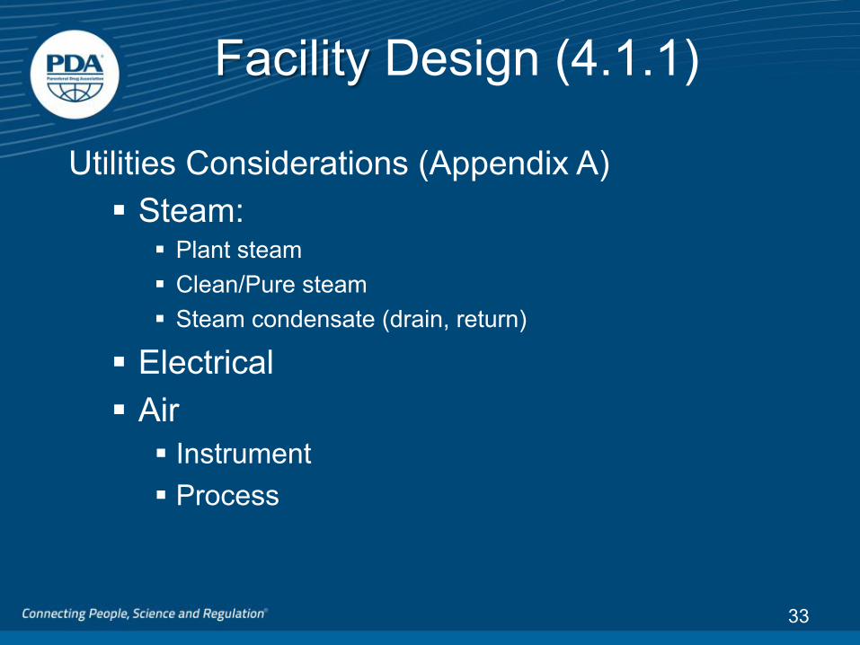
Facility Design (4.1.1)
Utilities Considerations (Appendix A) § Steam:
§ Plant steam § Clean/Pure steam § Steam condensate (drain, return)
§ Electrical § Air
§ Instrument § Process
33
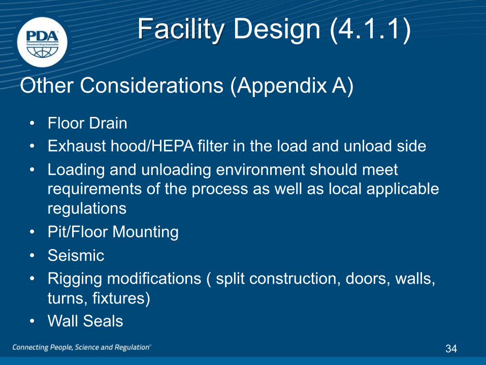
Facility Design (4.1.1)
• Floor Drain • Exhaust hood/HEPA filter in the load and unload side • Loading and unloading environment should meet
requirements of the process as well as local applicable regulations
• Pit/Floor Mounting • Seismic • Rigging modifications ( split construction, doors, walls,
turns, fixtures) • Wall Seals
34
Other Considerations (Appendix A)

Load Chamber
Service Access
Seal
Unload
Classification Y
Facility Design
Sterilizer Example: Load and unload areas are classified

Unload
Non-Contained Area
Chamber
Wall Seal Service Access
Load
Contained Area
Facility Design Sterilizer Example: Items are sterilized prior to removal from hazardous area

Section 5 Equipment Verification & Qualification

Equipment Verification and Qualification
38
Validate
Verify
Plan/Design Install
Ris
k A
sses
smen
t
DQ FA
T
SAT
IQ
OQ
PQ
URS FS DS
IQ/OQ Report
Ongoing Control Change Control/PM Engineering
Engineering Change Management
Commissioning
Risk Review and Mitigation
Production Construct
Stage 1: Process Design Stage 2 : Process Qualifica6on
Stage 3 Con6nued Process
Verifica6on
Equipment Verification and Qualification
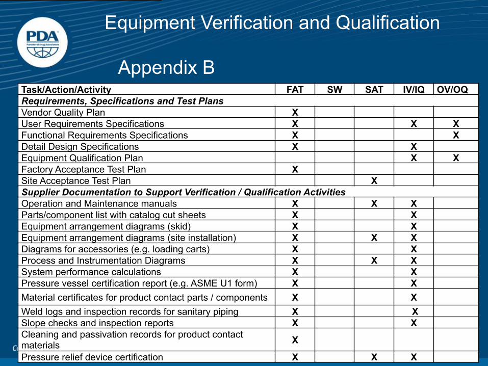
Appendix B
39
Task/Action/Activity FAT SW SAT IV/IQ OV/OQ Requirements, Specifications and Test Plans Vendor Quality Plan X User Requirements Specifications X X X Functional Requirements Specifications X X Detail Design Specifications X X Equipment Qualification Plan X X Factory Acceptance Test Plan X Site Acceptance Test Plan X Supplier Documentation to Support Verification / Qualification Activities Operation and Maintenance manuals X X X Parts/component list with catalog cut sheets X X Equipment arrangement diagrams (skid) X X Equipment arrangement diagrams (site installation) X X X Diagrams for accessories (e.g. loading carts) X X Process and Instrumentation Diagrams X X X System performance calculations X X Pressure vessel certification report (e.g. ASME U1 form) X X Material certificates for product contact parts / components X X Weld logs and inspection records for sanitary piping X X Slope checks and inspection reports X X Cleaning and passivation records for product contact materials X
Pressure relief device certification X X X

Equipment Verification and Qualification
Leveraging the FAT It is commonly recognized that testing executed according to GEP can make a significant contribution to validation exercises.
40

Equipment Verification and Qualification
§ Consideration for leveraging FAT § Acceptance approval (Quality standards) § Record keeping § Deviations § Control system revisions § Facility/Vendor Audits
§ Potential items to leverage § Drawing reviews § Alarm tests § Basic cycle sequencing § Software tests
41

Equipment Verification and Qualification
42
Steam Quality Testing should be conducted prior to Dynamic Equipment Qualification (OQ) Steam quality is determined through physical, chemical and endotoxin testing. Tests include: § non-condensable gases § super heat § dryness fraction for porous load sterilizers
(Section 5.2.1.1)

STERILIZER CHAMBER
Possible sources of air in chamber: Leak (during vacuum) in piping or door gasket
Insufficient prevacuum
Air entrained in steam
Add air detector
PACK AIR POCKET
SPORES
STEAM + AIR
STERILIZER DRAIN
STEAM + AIR
Air is generally a deterrent to sterilization A film of air only 0.0254mm thick offers the same resistance to the flow of heat as 1mm of water, 104mm of iron and 500mm of copper
Principles of Steam Sterilization
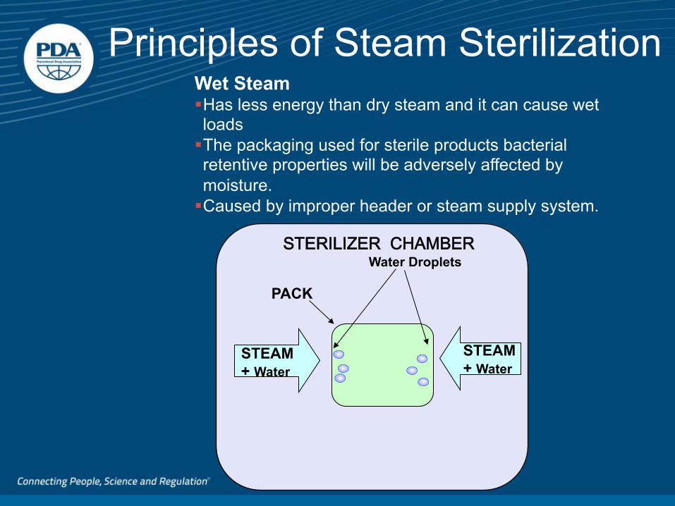
STERILIZER CHAMBER
PACK
STEAM + Water
STEAM + Water
Water Droplets
Wet Steam § Has less energy than dry steam and it can cause wet loads § The packaging used for sterile products bacterial retentive properties will be adversely affected by moisture. § Caused by improper header or steam supply system.
Principles of Steam Sterilization

Superheated Steam
§ Temperature above its boiling point for its pressure.
§ Gas that will not condense until its temperature drops to its boiling point.
§ Produced as the result of excessive pressure drops.
0
1
2
3
4
5
6
Steam Dry Heat
Exposure Time(Hours)
Principles of Steam Sterilization

Equipment Verification and Qualification
46
Steam Quality Testing
(Section 5.2.1.1)

Section 6-Cycle Development (Optimization)

Sterilization Process Cycle Development
Cycle development is the process of determining the physical parameters of the sterilization cycle that will be used to sterilize the component and/or equipment in a defined load pattern. The goal of the cycle development effort is to provide “a proven acceptable range” of critical parameters that will result in a product/material that is both sterile and functional after the sterilization process.

Cycle Op6miza6on Table-‐Sec6on 6 Saturated Steam Processes Air Overpressure Processes
Phase (Possible
Load Type)
Pre-Vacuum (Porous/Hard Goods Loads, Liquid Load Sealed Rigid or Non-Sealed
Container)
Gravity Displacement Process
(Porous/Hard Goods or Liquid Load (sealed/non-
sealed))
Steam Air Mixture Process (Liquid Load sealed
container)
Superheated Water Spray/Cascade
(Liquid Load sealed container)
Heat-Up Vacuum assisted or Forced Air Purge: Many sterilizers have a purge cycle programmed as the first step in porous/hard goods cycles. Pulses can be made more efficient by pre-empting them with a gravity purge. This may also reduce wear and tear of the pump system.as well as remove condensate in the load. Pulses: Alternating vacuum pulses and steam charges are used to condition the load prior to the exposure phase of the cycle. The number of pulses are load type dependent, typically 1-3 pulses are used for hard goods air removal; whereas, mixed or porous loads may require additional pulses. Vacuum depth: This parameter directly affects the amount of air remaining in the load. To optimize air removal for porous/hard goods heat-up generally begins with a deep vacuum pulse followed by a steam charge.
The rate of heat up and pressurization should be carefully controlled to prevent the liquid from boiling while removing the air from the chamber and head space of the container. Gravity purge: Time and pressure can be varied during development studies. Large and numerous steam supply and drain ports will facilitate faster and more effective air removal. During development, determine what temp to close vent(s) but leave open as long as possible.
The rate of heat up and pressurization should be carefully controlled to counter act internal container pressure developed as the liquid heats. This will prevent distortion and rupture of the container. . In addition, the heat-up ramp rates should be set under worst case conditions (full load of largest mass) so that the steam valve opening can maintain the desired ramp rate. Visual confirmation of container pressurization during the cycle may be helpful in establishing parameters during development. Ensure any trays used are adequately perforated to ensure steam/air/water circulation.
Since air overpressure is controlled, many are similar to the SAM process. The following parameters are those specific to this process. Chamber door is closed and sealed; water of appropriate quality enters the chamber to a preset level. Circulation system pumps water from the chamber floor through spray nozzles or water cascade grid located in the ceiling. Ensure spray nozzle placement covers the entire load configuration.

Sterilization Process Cycle Development
Hard Goods-Example § Air removal from the chamber and load
§ Component-mapping studies-TC placement § Load Patterns § Leak Rate Tests § Warm-up cycles

51
Sterilization Process Cycle Development
Temperature and Measurement Instrumentation Considerations: § Use of an appropriate thermocouple (TC)
wire § TC wire placement in the chamber or
items should not impede steam flow § Use TC wire of the smallest practical
diameter with consideration for application and risk to data integrity
§ Recording device accuracy § Number of available data acquisition
ports § Data collection frequency (scan rate)

Pressure
LEAK RATE TEST
PULSED AIR REMOVAL
Temperature Pressure Rated pressure
FORCED AIR REMOVAL
Temperature Pressure
EXPOSURE
Temperature Pressure
Temperature Pressure Rated pressure
VACUUM DRYING
PULSED DRYING
FAST AND SLOW EXHAUST
Temperature Pressure Rated pressure
Temperature in slow exhaust Pressure in slow exhaust Pressure in fast exhaust
Pre-Cycle
Heat Up Phase Pre-Conditioning
Exposure Phase
Cool Down Phase Post-Conditioning
Porous/Hard Goods (wrapped)
Vented Liquid Loads
Time/Temp F0
Wrapped Hard Goods
Porous Goods (Stoppers)
Metal, Vented Liquid Loads
Load Considera6ons Steriliza6on Cycle Phases

Cycle Optimization Saturated Steam Processes
Considerations During Heat Up • Vacuum Assisted Air Purge • Number of pulses • Vacuum Depth • Pressure • Rate of vacuum or pressure change • Hold Time
PULSED AIR REMOVAL
Temperature Pressure Rated Pressure

Considerations During Exposure Minimizing Equilibration Time • Time from achieving sterilization
temperature in the chamber and achieving sterilization temperature in the load – Steam pulses during Heat Up
‘condition’ the load
Fluctuation in Chamber Temperature • How quickly does the controller respond? • Are you maximizing the capability of the
proportional valve?
Temperature Pressure
EXPOSURE

Considerations During Drying
Dryness Assessment • How dry does your load need to be? • Deep vacuum lowers the boiling point,
but can your load withstand it especially with wet packaging/wrappings?
• Insure your vacuum is relieved by filtered air and not steam
• Leave heat on the jacket to provide radiant heat for drying
VACUUM DRYING
Temperature Pressure Rated Pressure

Using Temperature Profiles • Cycle Optimization uses temperature profiles
to determine the adequacy of air removal. Alternating vacuum and steam pulses remove air which, together with steam quality, determine the optimum cycle.
• A mixed load of porous and hard goods which includes filters, valves, tubing and open containers is demonstrated.
Cycle Optimization – Example

Problem with Heat Uniformity - Initial
0
20
40
60
80
100
120
140
16:06
16:08
16:10
16:12
16:14
16:16
16:18
16:20
16:22
16:24
16:26
16:28
16:30
16:32
16:34
16:36
16:38
16:40
16:42
16:44
16:46
16:48
16:50
16:52
16:54
18:12
Time
Tem
pera
ture
Cel
sius
1st Prevac
Poor Air Removal in 10" Filter Core, Bottom of 30" Core, and 30" Housing (Non-uniform heating)
Ramp-Up:Non- Uniform Heating of Chamber and Penetrated items
2nd Prevac3rd Prevac
Exposure Phase
Poor Steam Penetration after final pulse resulting in slow heating of 10" Filter Core
Cycle Optimization – Example

Cycle Optimization – Example
Problem with Heat Uniformity – Initial
• The slowest to heat area lags behind the other locations during early heat-up
• Corrective Action: vacuum level was increased

Problem with Heat Uniformity - Intermediate
Deeper Vacuum and Increased Ramp-up Time
0
20
40
60
80
100
120
140
Improved heating from better air removal. Needs more improvement
Poor equilibration time. The cycle needs additional optimization. Possibly long vacuum hold and additional pulses.

Problem with Heat Uniformity – Intermediate
• Drawing a deeper vacuum and increasing the ramp-up time improved the profile, however the cycle still needs significant improvement
• Adjustments are made to steam pressure, vacuum and hold times
Cycle Optimization – Example

Final Cycle - Optimized
0
20
40
60
80
100
120
140
Time
Tem
pera
ture
C
Uniform heating of the load items

Sterilization Process Cycle Development
Liquid Cycles § Load uniformity in heating § Fo sterilization-(no over-cook) § Overshoot § Cooling-jacket, spray, fans § Air-overpressure-during cooling-or entire cycle-Partial pressure liquid and vapor

Steam-Air Mixture Process Cycle
Chamber/Drain Temperature
Load Temperature
TEMP
ERAT
URE
/ PRE
SSUR
E
TIME
CycleStart
ChamberPressure
ChamberHeat Up Exposure Chamber
Cool Down
Steam-Air Mixture (SAM) Process
AtmosphericPressure
Sections 7 and 8 Ongoing Control/Documentation

On-Going Control Requalification § A procedural process that requires a written
protocol before performance of a test § Should be performed on a defined periodic basis
§ Annual or 3-4 months depending on criticality of the process.-Risk based
§ Empty chamber studies evaluate locations throughout a sterilizing unit to confirm uniformity of temperature and pressure conditions § Trend the temperature studies
65

On-Going Control Sterilizer System Maintenance § Ensure the equipment is maintained in its
qualified state § Maintenance planning should include what, when,
and how to perform preventive maintenance § Maintenance should be performed in conjunction
with calibration § Make sure you have vendor recommendations
and follow them § Predictive maintenance
66

On-Going Control Sterilizer System Maintenance § Maintenance planning may typically include:
§ Cleaning of the chamber, racks, shelving, and door
§ Replace door gasket(s) § Vent filter is sterilized and/or replaced
periodically § Steam traps cleaning and functional
verification § Check and replace valve seals/diaphragms
67

On-Going Control
Calibration § Detect and report all deviation from specified calibration
tolerance limits § May include adjusting the instrument, or a measurement
loop § Equipment should be calibrated according to a
documented program that includes establishing appropriate calibration intervals
§ Temp, pressure, transmitters, recorders, controllers § Two-point calibration
68

Documentation
69
Appendix C -Figure C-1 Documentation Qualification Level
Validation (Project) Plan
Change Control Documentation(Such as: Approval andCompletion Notification)
Validation Plan SummaryReport
On Going Report (Such as:Maintenance and Calibration
reports,Revalidation Plan and Report)
Validation Protocols (Suchas: DQ, IQ, OQ, PQ)
Validation Report
Specifications:DSFS
URS
Turn Over Package
FAT
SAT
System Manual
Spare Parts List
Supplier Test Report and Certidficates(Such as: Materials of Construction,
Welding Inspection, Pressure Test, andPassivation)
System Drawings (Such as: P&ID, WiringDiagrams, and Control System Drawings
Component and instrumentationDocumentation and Cutsheets
(specifications)
Installer Test Report and Certificates (Suchas: Materials of Construction, Welding
Certifcation, Pressure Test, andPassivation)
Risk Assessment Report
Cycle Development Report
Purchase Order
SOP (Sterilizer Operation andMaintenance)
Overall Project Planand On-GoingControl Level
Design andConstruction Level
Commissioning andTesting Level
Cycle Optimization Report
