technical report wrd83009 - territory stories: home · technical report wrd83009 ... find use in...
TRANSCRIPT

Technical Report WRD83009
Viewed at 14:07:54 on 29/07/2010 Page 1 of 46.
I I I I I I I I I I I I I I I I I I I I ,
~ CLASS NO.
6~g· 16&
,,: .... f\~- ,
DISINFECTION OF WATER, EVALUATION OF A SIMPLE CHLORINATOR WHICH USES CHLORINE-BASED TABLETS
(REPORT 91 i 983)
WATER
S. Taylor ~ D.Field Department of Transport ~ Works Water Division April 1983
LIBRARY DARWIN I
:::!.i
~CC. DATE
J.. TA'7 ':!%

Technical Report WRD83009
Viewed at 14:07:54 on 29/07/2010 Page 2 of 46.
I I I I I I I I I I I I I I I I I I I I
CONTENTS
Summary
Tabl~ of cont~nts
List of Figur~s
List of Tabl~s
Chapt~r 1 - Introduction and Obj~ctives
Chapter 2
Chapter 3
Chapter 4
Chapter 5
Chapter 6
S~ction 7
Cost of purchase, installation and operation of the syst~m.
Evaluation of the safety of the system.
Evaluation of the simplicity and reliability of the system.
Evaluation of th~ dosing control of th~ system, and its viability in the climat~ preval~nt in th~ Northern T~rritory.
Comments and conclusions.
Ref~rences.
Appendices. ( Note that this r~port contains as app~ndices technical manuals which also contain appendices ).

Technical Report WRD83009
Viewed at 14:07:54 on 29/07/2010 Page 3 of 46.
I I I I I I I I I I I I I I I I I I I I
SUMMARY This report describes the evaluation of a small chlorination system marketed under the name SANURIL. The system, although originally designed to disinfect wastewater, can be readily modified to enable it to disinfect drinking water. The device has no moving parts, and uses tablets containing chemicals which release chlorine, rather than using gaseous chlorine or chlorine-containing liquids.
The chlorinator is seen to be potentially useful as a method of disinfecting water supplies in small communities, and in those areas where the techni cal e}~pert i se necessary to operate more sophisticated systems is not available.
Since the equipment is supplied with detailed instructions and has been used elsewhere to disinfect drinking water, the evaluation detailed in this report was confined to three basics. Firstly, to determine that the device would withstand the climate prevalant in the Northern Territory. Secondly, to determine if it would give a controlled chlorine dosage under variable flow rates, and be reliable and safe. Thirdly, to make a cost comparison of the system against conventional gas chlorination systems.
The chlorinator is found to be adequate in the first two respects, and the invest i ga.tors have cone 1 u.ded that it caul d find use in certain areas and under certain conditions detailed in this report. The tablet chlorination system is inexpensive to purchase, but considerably more expensive to operate, than gas chlorination systems. Even so, it could still find use in the Northern Territory under certain circumstances.
The technical manuals associated with Sanuril chlorinators are appended to this report.
Technical Report WRD83009
Viewed at 14:07:54 on 29/07/2010 Page 4 of 46.
I I I I I I I I I I I I I I I I I I I I
LIST OF FIGURES
Figure 4.1 - Typical Sanuril Chlorinator, cut-away view, & View with cover removed.
Figure 4.2 - Typical Sanuril Chlorinator, with feed tube Removed, & showing tablet insertion.
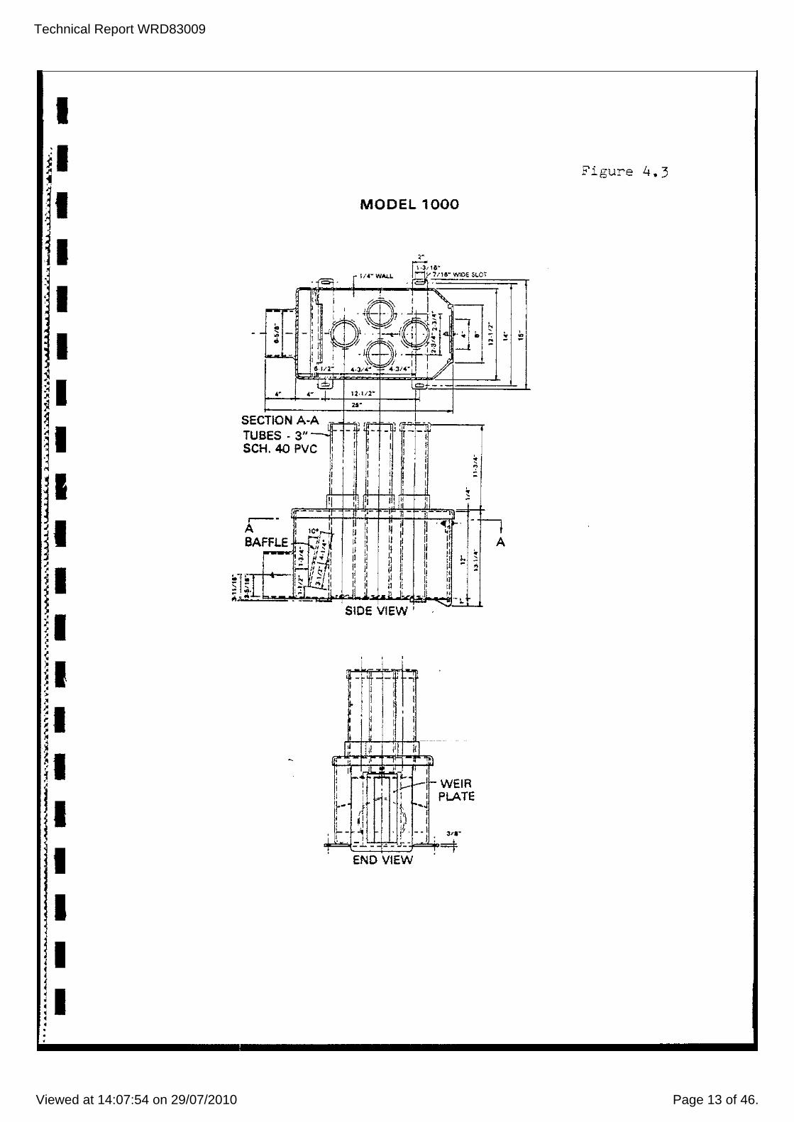
Figure 4.3 - Plan, front elevation and side elevation Of a Sanuril Model 1000 chlorinator.
Figure 5.1 - Design of the test installation.

Technical Report WRD83009
Viewed at 14:07:54 on 29/07/2010 Page 5 of 46.
I I I I I I I I I I I I I I I I I I I I
LIST OF TABLES
Table 2.1 - Cost Comparison - Tablet against gaseoLls chlorination.
Table 5.1 - Dates, times, flow rates, and chlorine levels during evaluation of the dosing control of the system.

Technical Report WRD83009
Viewed at 14:07:54 on 29/07/2010 Page 6 of 46.
I I I I I I I I I I I I I I I I I I I I
CHAPTER 1 - INTRODUCTION AND OBJECTIVES The Sanuril chlorination system uses chlorine-containing tablets in a simple metering device to treat water and can be adjusted to ~roduce a residual chlorine content in the water to a level suitable for either wastewater or potable water, as required.
The investigations detailed in this report were designed to evaluate the Sanuril system for drinking water disinfection with the following objectives:
.Determination of the cost of purchase, installation, and operation of the system. ( See Chapter 2 ) •
• Evaluation of the safety of the system. ( See Chapter 3 ).
.Evaluation of the simplicity and reliability of the system, including :Lts viability in the climate prevalent in the Northern Territory. ( See Chapters 4 and 5 I.

Technical Report WRD83009
Viewed at 14:07:54 on 29/07/2010 Page 7 of 46.
I I I I I I I I I I I I I I I I I I I I
CHAPTER ::2 -. COST OF PURCHASE, INSTALLATION AND OPERATION OF THE SYSTEM.
The equipment is simply constructed, from plastic components, and is relatively inexpensive. There are feur models of the chlorination system, designed to handle water volumes over an extremely wide range (see Appendices 8.3 to 8.6). The model 1000 unit was purchased for evaluation .. CLtrrent costs are as follows:
Model 200 chlorinator Model 100 chlorinator Model 1000 chlorinator Model 1001 chlorinator
$:;;00-00 $,300-00 $32()-OO $320-00
The chlorinators are constructed from polyvinyl chloride. The devices are also available made in fibreglas. if required, at the following costs:
Model 200 Model 100 Model 1000 Model 1001
The current cost of 1 Only 20 kg. Pail 10 Off 20 kg. Pails
$440-00 $440-00 $A60-00 $460-00
the chlorine tablets is as follows: $140-00
$1350-00
70% Of each tablet is available as chlorine. This means that 1 kilogram of chlorine costs $10 when purchased as part of a 20 kilogram pail of Sanuril 115 tablets.
Installaticn costs would be minimal, not including the cost of shipping equipment and personnel to the installation site. Essentially, the device is attached to the end of the pipe discharging into the holding tank or header tank to the water supply, and then calibrated under average conditions and checked throughout its expected operating range. The Sanuril system was originally designed for wastewater disinfection and some small changes are required to bring chlorination dosage levels down to those required for potable water dlsinfection. There is no doubt that any competent pI c!mber coul d readi I y install the equipment for little cast. The major cost involved would be the costs of personnel during the calibration period. This period would be in the order of several hours, and ",ould reduce as the installers gained experience in the operation of the equipment. In this respect the tablet and gas chlorination systems are similar.
By comparison, the aproximate cost of a small gas chlorination system is $1800-00. This is a cost for a goad-quality system including the following components:
High-pressure injector Vacuum regulator Wall-mounted manifold ( heated ) with filter and flexible connector Pressure gauge.

Technical Report WRD83009
Viewed at 14:07:54 on 29/07/2010 Page 8 of 46.
I I I I I I I I I I I I I I I I I I I I
The current price for chlorine as chlorine gas sold by I.C.I. is $1-01 per kilogram, plus the rental charge on the cylinder. Rental charges for cylinders are presently $15-00 per cylinder per month. The Northern Territory has two months free rental of cylinders. Thus, depending on rental charges and chlorine usage, tablet chlorination could cost nine times more than gaseous chlorine water disinfection.
Not including installation and shipping costs, a gas chlorination system costs approximately $1800-00 to commission, and a Sanu1'"il chlorination system costs app1'"oldmately $$460-00.
TABLE :2.1 I:OST COMPARISON
Type
Gas Tablet
Capi tal
$1800 ~r.320
Chlorine
$1-01/kg. $10-00/kg.
Installation
Similar Similar
Transport
greater lesser
It can readily be seen that the cost of operation of the Sanuril system is greater than that of a system using gaseous chlorination, simply on the basis of the cast of the tablets. However, there are same considerations which offset this disadvantage. Bearing in mind that the device is being evaluated for small communities having little if any technical skill, it ~s quite likely that such a community would be incapable of ensuring that a gas chlorination system would be operated satisfactorily.
Once the tablet chlorination system is calibrated, maintenance consists only of adding tablets to the chlorination tubes. This would be required on an infrequent basis, and the skill level requi red waul d be rather I ess than tha.t necessary to add chlorine compounds to a domestic swimming pool.Thus, the1'"e are no gas metering and measuring devices to damage, and no heavy and potentially dangerous chlorine gas cylinders to move around.
Delivery costs of tablets would be less than the cost for a supply of gas having the same chlorine content, and the tablets are much easier to handle, particularly wlth respect to delivery b)' aircraft. ( Note that··special handling arrangements would still be 1'"equired, in accordance with Air Navigation Orders 33.1 and 33.2 - see reference 6. Freight costs for Sanuril 115 tablets are less than the costs for chlorine cylinders, and the freight costs for chlorine c)'linders apply travelling to site full and away from site empty. Empty Sanuril tablet pails ma), be discarded.
The costs detailed above apply as of April 1983. ( See references 1,2,& 3).
There are other chlorination systems which use neither chlorine gas, nor chlorine-containing tablets. One system was proposed by Allan, (see reference 4). In the evaluation detailed in this report, tablet chlorinat-ion has been compared only with gaseous chlorination.
./

Technical Report WRD83009
Viewed at 14:07:54 on 29/07/2010 Page 9 of 46.
I I I I I I I I I I I I I I I I I I I I
CHAPTER 3 EVALUATION OF THE SAFETY OF THE SYSTEM
There are two aspects to the question of the safety of the tablet dispensaticn system:
1 The inherent safety of the disinfection of water for drinking using Sanuril tablets.
2 The safety of the tablets as stored material when compared with chlorine gas.
3.1 DISINFECTION USING SANURIL TAELETS.
There was some content i on as to the s,_,i tabi 1 it Y of the chemicals used in Sanuril 115 tablets for potable water disinfection. This was resolved when information was received from the Department of the Environment ( a British Government Department ), that the materials were acceptable, providing that the disinfection dosage upper limit for potable water was not exceeded. This dosage is 2mg/L of Sanuril and is the equivalent of 0.5 mg/L of free chlorine ( reference 4). Variation of the chlorine dosage outside the specified limits is considered to be a small risk and ore which is unlikely to occur, given that the device is properly installed. Assuming that the system is not interfered wlth, and that the tablets are added as necessary, it should be stable. The manufacturers claim 15% accuracy in dosage control, which is adequate.
Technical advice on the installation and operation ·of Sanuril systems is readily available from the suppliers in Australia. ( See Appendices 8.1, 8.3 to 8.6, ).
3.2 SAFETY OF THE TABLETS AS STORED MATERIAL
It has been established that hypochlorite in tablet form ( as in Sanuril 115 tablets) is safer than chlorine gas stored in cylinders (see reference 4). It is not completely safe. The risk associated with Sanuril 115 tablets is that they contain a strong 0:< i dl sl ng agent and can spontaneousl y i gn i te or create explosions when placed in combination with certain other materials. The tablets are also toxic, can produce poisonous gas ( chlorine ), and cause skin irritation. These risks may be compared with the risks associated with stored petrol - a more generally recognised hazardous material. The risks asociated wih Sanuril 115 tablets are the same risks taken by people who store and use sw-imming pool disinfection chemica.ls containing sodium hypochlorite.
In the circumstances it appears that there is no abnormal risk in using the equipment when compared with other methods of disinfection.

Technical Report WRD83009
Viewed at 14:07:54 on 29/07/2010 Page 10 of 46.
I I I I I I I I I I I I I I I I I I I I
CHAPTER 4·- EYALUATION OF THE SIMPLICITY AND RELIABILITY OF THE SYSTEM.
The device is very simple ( See Figures 4.1, 4.2, and 4.3 ). There are no moving parts, and no power is required to operate the system. When used to disinfect water for drinking, the unit is installed at the inlet point to the mixing tank of the water supply. A by-pass tube and valve diverts a proportion of the water being delivered to the system directly into the mixing tank. The remaining water passes through the chlorinator and contacts the chlorine-containing tablets, then falls through a weir into the mixing tank, mixing with the by-passed water.
The weir controls the water level in the =hlorinator in response to flow rate, and thus automatically controls chlorination by immersing the appropriate number of tablets into the water. The tablets are stacked in vertically mounted slotted tubes.
The device is calibrated by estimating flow rate and then inserting one of the weir plates into it as appropriate. The weir plate selected will control the wate~ level in the chlorinator as flow rate varies. One or more o·f the feed tubes are sta.cked with Sanuril 115 tablets as aopropriate; the water supply is ~hen turned on and the by-pass feed rate is adjusted using the by-pass valve.
The chlorine quantities in the mixing/holding tank are measured over a period of time and when a satisfactory result lS consistently noted the installatlon is complete.
The reliabIlity of such a simple device is probably more affected by human error than any other factor. For example, if the chlorinator is not supplied with tablets, it will not disinfect the water. This possibility is minimised by allowing a large quantity of tablets to be stored in the device in such a way that they will move down into the water under their own weight as tablets are consumed. It is arguable that infrequent servicing requirements could result in a complete failure to service the system, as the people whe should service it have forgotten aboL!t it.
It is possible that the chlorinator could become blocked by material carried-in the water and by residues from the tablets. This is unlikely, as the water would not be carrying large quantities of suspended material ( f~r it '''''QuId not be in use as a potable water supply), and the Sanuril 115 tablets are specially designed not to crumble. ( See ."ppendi,,, A). In the event that the device did require cleaning, then this could be very easi I y done by unski 11 ed personnel.
The possibility that the system could fail through deteriorati.on of its components in the monsoonal climate prevalent in the Northern Territory was considered. This has nat occured ( see Section 5 ).
The reliability of the device as a chlorination dosing system for drinking water was evaluated, and the details appear in Section 5. The Sanuril system is reliable.

Technical Report WRD83009
Viewed at 14:07:54 on 29/07/2010 Page 11 of 46.
I I I I I I I I I I
• -. I I I I I
• I II
FEED TUBES -,- ! I I J !-j t
I ~~,J..I-l
WATER OUTLET
WATER ~i I I
1NLET'ts. _~~ ~r"ill.-r:r
SANURIL 115 TABLETS
Cut-Away View SANURIL ChlQrinator
•
TOP COVER
WEATHER-PROOF CAPS
Cover Removed Showing Weir Plate and Baffle
Figure 4.1

Technical Report WRD83009
Viewed at 14:07:54 on 29/07/2010 Page 12 of 46.
I I I I I I I I I I I
:1 I I I I I I I I
I •
FEED TUBES ~~t
COLLAR I .
SLOTS ~': ,.~ 1 ·W ~
TOP COVER
Muu;:"NG
Chlorinator Feed Tube Removed ~~
WEATHER-PROOF CAP
.-- 'rl::I::U TUBE
~SANURIL 115 TABLETS
( "
Charging SANURIL 115 Tablets
F'i~ure 4.2
Technical Report WRD83009
Viewed at 14:07:54 on 29/07/2010 Page 13 of 46.
I
~I :1 41 I I
I I I
MODEL 1000
SECTION A-A, -, ,- - " r,r-o.An TUBES-3,,-JI- -, ,- -, I--f SCH. 40 PVC 'I i', I", ,
I l ' 1 ~ l I I I ' I I I ~ , ,I I I' : I j J I I I
-n A
SIDE VIEW'
f.-rt- - ~r I , ' I ' I I I . I
'I I , ~ :
, , ..
I" ,I "
Il • ,. , , , • I , "", lb-II--, , ,
, - I ,
r- Ii - • j \-,J . ') ,
I I' 'j , , " .... - 1 . I' --, i '. _ ..::. '_ :.1::"-
I : -"--
END VIEW
-
WEIR PlATE
Figure 4.3

Technical Report WRD83009
Viewed at 14:07:54 on 29/07/2010 Page 14 of 46.
I I I I I I I I I I I I I I I I I I I I
CHAPTER 5 - EVALUATION OF THE DOSING CONTROL OF THE SYSTEM, AND ITS VIA8ILITY IN THE CLIMATE PREVALENT IN THE NORTHERN TERRITORY.
Water Supply personnel installed the system at the Water Division's 19 Mile Pump Station, the work being completed on 14/12/1981. This site was selected because-A) it was close to Darwin, and access was easy, B) water from the Darwin River Dam main pipeli~e ( a raw water
source) can be used, C) security was available.
Figure 5.1 shows the design of the installation, which was quite basic. Two 200 litre drums were used as mixing and holding tanks, the mixing tank receiving water from the chlorinator and the by-pass pipe. Metered connections were made to the chlorinator and the by-pass pipe.
The Sanuril 1000 chlorinator was set up as detailed in the suppliers manual and the resldual chlorine content of the system was determined using DPD tablets and a Lovibond comparator ( see Appendix Bl. Measurement of residual chlorine content is a quick and convenient method of assessing the dosing control of chlorination systems (see reference 6 ). Sanuril tablets are known to be effective in disinfection, thus bacteriological tests were not necessary in this investigation. The investigation showed that adequate chlorine was being applied for the disinfection of water from an unpolluted source. The investigation to 17/12/81 demonstrated that it was difficult to achieve controlled dosing for small flows with the Sanuril 1000 chlorinator as supplied. This was probably because the Sanuril device purchased was not the unit available capable of handling the lowest flows and it was operating at the extreme end of its working range. The unit was modified slightly; the modifications consisted of blocking off most of the slots in the only feed tube which contained tablets, and replacing the weir plate with a plate containing a vertical row of holes.
The effect of these changes was to raise the level of water in the chlorinator, improving contact with the tablets. Small particles of the tablets were also retained in the chlorinator and dissolved in ~he water. This effectively ~esulted in trickle chlorination using a chlorine brine solution.
The device was ready for extended trials at this point, when staff were instructed to cease work on the project. An instruction to re-commence the investigation was received some months I atel~.
Trials commenced on 26/11/82 and continued until 17/12/82 under difficult circumstances. The source water pressure was low and variable. Flows were at approximately 1 L/minute during this period, compared with 15 L/minute when the device was

Technical Report WRD83009
Viewed at 14:07:54 on 29/07/2010 Page 15 of 46.
, I 1 Inlet- raw WQ',er ]-:;-'1 C"l'T'c. ,-~. 'I
- -.:::...,,' '- -':= ~
I .' I
~Meter ( M
[;.-- Sanuril 100 Chlorinator
, I
I I
~ ,-Outlet via weir
I '- ~\ ~'\
~ 1\~~
I r
I ! To supply
• . Mixing Tank Holding Tank :. :. - • •• :, :. • • • I

Technical Report WRD83009
Viewed at 14:07:54 on 29/07/2010 Page 16 of 46.
I I I I I I I I I I I I I I I I I I I I
installed. Despite this problem, the outlet residual chlorine quantity in the water varied from only 0.1 mg/L to 1.0 mg/L. Only occasional adjLlstment was required (see Table 5. 1 ).
The system was then moved to a more representati ve ",ater supp I y source for evaluatlon with higher and more variable flow r-ates.The unit was installed at Sasco House in Darwin, and connected to the water supply for the building. Since the intention of the project was to evaluate the system as supplied by the manufacturers, the unit was fitted with a standard weir plate and ':ablet feed tubes.
At flow rates of 16 to 17 L/minute, and with flow through the chlorinator adjusted to a mlnimum such that water could just contact the tablets, it was possible to obtain a stable residual chlorine quantity of 1.0 mg/L. The proportioning of chlorinated water to by-passed water was 0.14 L/minute chlorinated water to 16 L/minute by-passed water. The residual chlorine level can be expected to be lower in water having a higher chlorine demand. ( The water supply to Sasco House is already ch!.orinated ). For detai Is, see Table 5. 1.
The chlorinator was exposed to the cLimate prevailing in Darwin from 14/12/81 to 17/12/82, approximately ane year. The device was given 110 maintenance, and had no roof or other shielding. The only change detectable uSlng facilitias available to the investigators was a slight colour fading. The components of the system did not appear ta have become brittle, crazed or soft. The system has not been evaluated to determine its viability in arid climates - see Chapter 6.

Technical Report WRD83009
Viewed at 14:07:54 on 29/07/2010 Page 17 of 46.
I I I I I I I I I I I I I I I I I I I I
TAELE ~.1 - OATES, TIMES, FLOW RATES AND CHLORINE RESIDUAL CONCENTRATIONS DURING EVALUATION OF THE SYSTEM.
Date Time
14/12/81 1400 14/12/81 1500 15/12/81 1216 15/12/81 1250 15/12/81 1400 17/12/81 (":;)35 26/11/82 1115 26/11182 1300 01/12/82 1400 02/12/82 0330 06/12/82 1110 17/12/82 1110 25/2183 1250 25/2/83 1333 25/2/83 1408 25/2/83 1423 25/2/83 1600 28/2/83 1254 28/2/83 1336 01/03/83 1130 01103/83 1218 01/03/8.3 1323 01/0.3/83 1705 Expl.n.tioI1 of Ter-ms used:
I = B -C -[] = M = H = 0 -* -
** = *~*'* =
Mg/L = L/min =
Weir- =
Weir- Flow r-ate L/min Chlor-ine Residual mg/L I B C [] t1 ~l
6 6 6 6 0 0 0 0 0 0 0 0 ~
"-2 2 2 2 2 2 2 2 2
12 .. 5 0 12.5 12.5 ?
12 .. 0 6.0 6.0
13.3 11.5 1.8 0.9 0.82 0.08
1.8 16.5 16.5 16.5 16.5 16.5 13.0 13.0 17.5
16 .. 0 0.5 16.850.15 16.85 0.15 16.85 0.15 16.85 0.15
0 .. 04 0 .. 04
17.36 0.14 18.5 U3. 39 I). 11
2 19.5 T.ble:
0.08
65 40 2.7
40 28
Flow r-ate at inlet to system Flow r-ate thr-ough by-pass pipe Flow r-ate through chlorinator
5.5 "5" 5
>4 .. 0* 0.5 0 .. 9 .3.0 0.:2 (J" 2*-1(-1 .. 5 0.4 4.5
4.5 5 .. 0 5.0
>4 .. 0 O. 1 0 .. 2 1.0 0 .. 1 0.1 0.1 0.2 2.7*** 0.5 1.0 1.0 1.0 0.8 1.2
1.0 0.8 0.6
Chlorine Residual level at chlorinator outlet Chlorine Residual level at mixing tan~(
Chlorine Residual level at holding tank Orilled plate substituted for- weir plate High residual due to insufficient flushing after disturbing chlorinator No adjustments made from 2/12/82 to 17/12/82 Chlorinator tap closed 0.25 turn~ no further adjustments made milligrams per litre Iltres per minute slot width of the weir plate, in millimetres

Technical Report WRD83009
Viewed at 14:07:54 on 29/07/2010 Page 18 of 46.
I I I I I I I I I I I I I I I I I I I I
CHAPTER 6 COMMENTS AND CONCLUSIONS 6.1 The Sanuril chlorinator is inexpensive to purchase and
install. 6.2 - It is more expensive to operate than a gas-chlorination
system, but this disadvantage may be offset by other considerations such as the technical skills of the operators and/ar the circumstances in which the system is to be Ltsed.
6.3 - The Sanuril system could be transported to site by light aircrafy and be installed and operational within minutes of arrival. in cases of epidemic this could be very important.
6.4 - The device could also find use in large temporary communities, such as mining and construction camps. ( The Tasmanian Hydroelectricity Commission use Sanuril systems for potable water treatment in temporary campssee reference 5). In these situations the actual running cost. of the system may be quite acceptable when the convenience of the system is compared with the convenience of operating a gaseous chlorination system.
6.5 - The trials conducted to evaluate the device ware brief. This brevity was allowed on the basis that the information available to any purchaser is detailed and accurate enough to prec 1 ude a more e){tensi ve and expensive evalLlation process. Copies of the manufacturers information supplied to the Water Division are included in this report, in Appendicas 8.1,8.3 to 8.6.
6.6 - The trials showed that the Sanuril system can be used to reliably chlorinate water supplies using tablets, and that the unit will withstand the monsoonal climate prevalent in the Northern part of the Northern Territory. The device could be evaluated in arid zones simply by being placed in a secure area in such a zone and E?}<amined periodically.
6.7 - The problems associated with chlorine dosing using the equipment under low waterf lows ShOLli d not be regarded as significant, since there are sm~ller Sanuril chlorinators which operate using exactly the same principles as the device used in the evaluation, and these units would have oper",ted without modification at the low flo~, rates experienced, producing reliable chlorination dosages» At greater f'low rate's, the system operated adequatel y.
The technical information contained in Appendices 8.3 and 8.4 in Section 8 illostrates the wide range of water volumes which the equipment can be arranged to handle.
In the tests, two 200 litre drums were used as holding and mixing tanks. This 400 litre capacity is inadequate to buffer the variations in chlorine content caused by surges in the water supply to the system, or by internittent operation. A tank of the type commonly used in small communities as a header tank would readily absorb the variations, allowing better mixing and more exposure time for the chlorine to disinfect the water.

Technical Report WRD83009
Viewed at 14:07:54 on 29/07/2010 Page 19 of 46.
I I I I I I I I I I I I I I I I I I I I
SECTION 7
Ref erence "
Reference 2
Reference 3
Reference 4
Reference 5
Reference 6
REFERENCES
Chlorlne gas costs and cylinder rental charges - Imperial Chemical Ind~stries, Adelaide.
Gas chlorination systems -Fisher and Porter, Adelaide.
Sanuril chlorinators and Sanuril 115 tablets -Diamond Shamrock/Australia, Melbourne.
Watel"" Division Fi Ie WP5/31 (2), Investigations Branch, Department of Transport and Works, Darwi n, N. T.
Telephone conversation, G. Shepherd, Manager, 8iosciences~ Diamond Shamrock Australia
·Standard Methods for the ENamination of Water and Wastewater", A.P.H.A., A.W.W.A 14th edit., 412 A ' Method for control of Disin·fection " p.359 ..

Technical Report WRD83009
Viewed at 14:07:54 on 29/07/2010 Page 20 of 46.
I I I I I I I I I I I I I I I I I I I I
APPENDICES
Appendix A - Sanuril 115 tablets.
Appendi ,., B
Appendix C
Appendix D
Appendix E
Chlorine assay technique.
Sanuril Model 1000/1001 Instruction Manual.
Sanuri 1 Model 100 Instruction ~lanual.
Manufacturers notes on Adaptation of Sanuril Model Model 100 for Potable water treatment.
Appendi:( F - Manufacturers nates an Adaptation of Sanuril Model Model 1000 for F'otable water treatment.
00000000000000000000000000000000000000000000000000000000000000

Technical Report WRD83009
Viewed at 14:07:54 on 29/07/2010 Page 21 of 46.
.i;.ppendix A
I DISINFECTING AGENT I For Wastewater Treatment
I GENERAL
of disinfecti~,g sewage. I SANURIL 115 puts an end to the problems
I Currently, wastewater treated by small pack·
age sewage treatment plants is disinfected by chlorination methods which require expensive equipment, need regular maintenance and re-
I pair ... costly factors ... and except for high· priced models, these methods deliver chlorine solutions at a constant rate and do not compen·
I sate for variations in the effluent flow rate.
These objections are overcome by SANURIL 115*, a recently-developed chemical specifically suited for disinfecting and sanitizing sewage,
I especially from package sewage treatment plants. Check these advantages:
• Rapid Bacteria Kill
I • Bacteria Regrowth Control
• Less Chemical Required To Do The Job
I • High Chlorine Content
• Easy To Handle Form
I • Dissolves Evenly
SANURIL 115 is dispensed into the effluent stream with a specially-designed low cost chlor-
I inator. Used together, SANURIL ll5 and its chlorinator provide many operational advantages:
I I I I I
• Complete System For Wastewater Disinfection
• Controlled Chlorine Dosage
• Long-Term Operation
• Eliminates Need To Handl,e Toxic Gases
• Eliminates Expensive Equipment SUCh As Pumps, Tanks And Flow Meters
• Eliminates Need For Bulky Solutions, Electrical Power And Auxil ia ry Water
• Automatic Operation
• Minimal Maintenance And Operating Cost
• No Moving Parts That Wear Out And Have To Be Replaced
-EPA Registration Number 677-274.
DESCRIPTION
The form and .composition of SANURIL 115 provide a sanitizing agent with properties supe· rior to commercially available products for sewage effluent sanitization. SANURIL 115 also provides a source of stabilized chlorine which serves to minimize bacteria regrowth.
COMPOSITION
Chlorine Content, min. Product Form Dimensions Weight, approx, Density Crumbling Wicking Breaking
Caldum hypochlorite and 1,3,4,6-Telrathloroglyt:llluril*
70% Tablet 2%' dia., 13/16' thick 412 oz. 83 Ibs./ft.' None None None
• Patented under U.S, No. 3,165,521 and U. S. No. 3,445,383
TESTS
Laboratory and field tests have shown that the features and advantages of SANURIL 115 confirm its value as an efficacious agent for the disinfection of treated sewage effluent and other wastewaters.
Germicidal potency of SANURIL 115 was de· termined by using the Available Chlorine Ger· micidal Equivalent Concentration Test outlined in the 10th edition of Official Methods of Analysis of the Association of Official Agricultural Chemists,
The results of the test (See TABLE I) show that SANURIL 115 is superior to sodium hypochlorite in its activity against the organisms used in this standard test procedure.
I All r.t1:ommerJd~tiOI"l5 U1d sugge$Ooru appe.uing in this bullelin concerning the use of our p:OOUCI.s are b~ed upon tests and d-1ta believed !o be leliabre. Since the actu<z{ us~ by olh~n is beyond O(1T conllol, no 811aantee, expresseo or implied, is made by Diamond Shamfoc~ CO'poration as to the efiects of such IJse or the re;uJts to be ,00' c.Jrt'led, nor is .any miormation 10 be construed as ~ l~comme:JdatJOll to infringe any patent or to prac!Ice .my process in violation of any {,J,wor ,my govemment resulatloft.
I I
~ DIAMONO SHAMROCK COR?ORATlON 1974

Technical Report WRD83009
Viewed at 14:07:54 on 29/07/2010 Page 22 of 46.
I .. T A BS~~U~lL 115 Bactericidal Activity • Laboratory I~esults
Comparison with Sodium Hypochlorite
Test No.
scherichia coli Samplel
1 SANURIL 115 2 NaOCl
almonella typhi
Available Chlorine,
ppm2
1.0 1.0
pH
7.1 7.5
Avg. No. Inoculum
Increments Killee'
2 o
3 SANURIL 115 0.5 7.1 2 4 NaOCl 0.5 7.5 1
. OJ,stiHed water we$. used in all caS(ls. Temperature was 75'" F.
. Total avai!!lble chlorine was determined by the iodometric titf.!!tl-on metilo:;j prior to testing.
, Number of 0.05 ml. inoculum Increments added at one minute interv~h: killed by test mixture in one mJnute (ayerage of duplicate determin~tions).
In another test, SANURIL 115 and calcium hypochlorite were compared for effectiveness in treating sewage. A sample of effluent from an
If3:ctivated sludge sewage treatment plant was ~ivided into two portions and each portion re
spectively, was treated with an equivalent amount of calcium hypochlorite and SANURIL
.l15. The results (See TABLE II) show that ~ANURIL 115 is comparable to calcium hypo
chlorite in its effectiveness against E. coli. How-.:ver, SANURIL 115 is superior to calcium hypo.-;:hlorite alone in that the synergistic blend of
active ingredients provides a more rapid reduc· tion of organisms and, a measure of control
l against the bacteria regrowth. Other test data is available on request.
TABLE .. Comparison of Calcium Hypochlorite and
SANURIL 115 Against E. coli Present in a Treated Sewage Effluent
Calcium SANURIL Sanitizer Hypochlorite 115
Initial Dosage, ppm chlorine 1.7 1.7 Chlorine Residual, ppm
at 0.5 hour 0.63 1.30 at 5 hours 0.31 0.95 at 24 hours 0.00 0.00 -Initial E. coli conc./lOO ml. 3.7 X 10' 3.7 X 10'
Remaining E. coli /100 ml. at 0.5 hour 2 x 10' 1 X 10' at 5 hours 1 x 10' 0 at 24 hours 4 x 10' 0
divided into two equal portions and each portion was simultaneously treated with one of the disinfecting agents.
The results in Table III show that the use of SANURIL 115 achieved superior bacteriological reductions, compared to calcium hypochlorite, and required about 20% less sanitizer to do the job.
rTABLE III Comparison of Efficacy and Consumption of
SANURIL 115 and Calcium Hypochlorite in Treating Sewage
Test Period, days Est. Plant Flow, gpd Sanitizer Consumption, Ibs./day Initial E. coli/lOO ml.,
range Average E. coli Remaining
After 0.5 Hour Detention Time'
% E. coli Reduction, avg. a. Based on eight determinations.
SANURIL 115 16
3.5 X 10' 0.137
4x 10⁴ -
1.14 X 10⁵
625
98.3
Calcium Hypochlorite
16 3.5 X 10'
0.172 4 X 10⁴ -
1.14x10⁵
5475
88.1
SANURIL WASTEWATER CHLORINATOR SANURIL 115 Tablets were developed for use with the SANURIL WASTEWATER CHLORINATOR shown here. It was designed to be used with sewage treatment plants having capaci· ties of up to about 100,000 gpd.
\ .. I
-
The Chlorinator consists of a dissolver through which treated sewage effluent flows, feed tubes for applying the tablets and a weir plate to automatically control sanitizer dosage. Constructed of durable corrosion-resistant materials, the Chlorinator is 22" long, 13" wide and 13" deep and contains four sanitizer feed tubes which hold the SANURIL 115 Tablets.
CAUTION - S~.NURIL 115 is a strong oxidizing agent and care shoul<l be taker in handling and storing the product. Additional warning statements and specific instructions on using, handling and storing SANURIL 115 are contained on the product label.
A field test was conducted over a period of Leveral days to evaluate SANURIL l15 as a .sewage effluent disinfectant and to compare it
to calcium hypochlorite. The effluent from an rctivated sludge sewage treatment plant was
Dia'110nd Sha.nrock I
Printed in U.S.A.
I
ELECTRODE CORPORATION· SANURI_ SYSTEMS P.O Box 348 . Palr.€sville, Ohio 44077
R-SL·3A

Technical Report WRD83009
Viewed at 14:07:54 on 29/07/2010 Page 23 of 46.
I I I I I I I I I I I I I I I I I I I I
APPENDIX B Measurement of residual chlorine concentrations
Residual chlorine levels were assayed using a Lovibond 1000 comparator fitted with a standard Lovibonj disc appropriate to the concent.ration range of the residua.l chlorine i .. e disc 3/40A, 3/408, or 3/40D. Dilutions were made as necessary. The method used was that employing N,N - diethyl-p-phenylene di ami ne ( f"al in DPD ), that reagent bel ng compounded in what 1 s known as B.D.H. number 4 tablets. This method is used routinely for ehlorina assay in reticulated supply monltoring in the Northern Territory.

Technical Report WRD83009
Viewed at 14:07:54 on 29/07/2010 Page 24 of 46.
I I I I I I I I I I I I I I I I I I I I
Sanuru·· Appendix C Models 1000/1001
0(> Diamond Shamrock Wastewater Chlorinator
Instruction Manual
Installation • Operation • Maintenance

Technical Report WRD83009
Viewed at 14:07:54 on 29/07/2010 Page 25 of 46.
I I I I I
•• I I I I I I I I I I I I' I I
MODELS ". -" ,,~, .
1000-1001·;,;'·.·.··.·<··;· .. ~ '- -.".r··' ... ' " .. -~ .-;"" . 1"-...
'<;~_'~"" ·'.i 'c ., - ~ ~ .. ''''''''''
Instruction Ma . , ' -,' '.'"
" .
INSTALLATION
The SANURIL Wastewater Chlorinator is a complete, one piece chlorination system designed for disinfecting the total flow of treated wastewater from any sewage treatment plant with a daily capacity of up to about 50,000 gallons. Two chlorinators in parallel will handle plants with capacities as high as 100,000 gallons per day .
Two models are available .. , the convenient Model 1000 with a 6 inch pipe inlet or the versatile Model 1001 with solid inlet end for easy field adaptation to the outlets of existing plants.
The SANURIL System consists of a compact, adjustable chlorinator (See Fig. 1) which dispenses a pre-determined quantity of SANURIL 115 ... a new disinfecting agent in tablet form which provides a stable source of chlorine for disinfecting the wastewater. (See Fig. 2.)
Fig. 1 - SANUR1L Wastewater Chlorinator
---

Technical Report WRD83009
Viewed at 14:07:54 on 29/07/2010 Page 26 of 46.
I I I I I I I I I I I I I I I I I I I I
Fig 2 - SANURIL 115 Tablets
SANURIL Chlorinator
The chlorinator is of simple design with no moving parts. It is manufactured of molded fiberglas and polyvinyl chloride for durability and resistance to corrosion. Each chlorinator is equipped with four removable feed tub6s in which the charge of SANURIL 115 tablets is contained. (See Fig. 3.) The tubes are inserted down through the removable top cover of the chlorinator into the stream of wastewater. The lower end of each tube is slotted to permit free flow of water through the tubes to assure good contact between the water and disinfectant tablets.
:-~ FEED TUBES
;~
.' \,,~ "
Fig 3 - Chlorinator Feed Tube Removed
co. .. I L
TOP COVER
HLIl ",ING
Ams WEATHER-PROOF CAP
Each chlorinator is furnished with a selection of weir plates. with weirs ranging in size from 1 to 3 inches in width, for insertion at the outlet end to control the internal water level, depending upon plant capacity and the residual chlorine required. (See Fig. 4.) The feed tubes have been precisely located in a diamond shaped pattern, a baffle is installed at the inlet end and the outlet end is contoured for proper water velocity and flow direction.
WEIR PLATE
\' -, HOUSING
Fig. 4 - Cover Removed Showing Weir Plate and Baffle
The entire chlorinator assembly is compact and easy to handle, measuring only 21 inches long, 12-1/2 inches wide and 13-1/4 inches deep. The feed lUbes are 24 inches long and with .an outside diameter of 3·1/2 inches. Each tube holds 29 SANURIL 115 tablets which measure 2-5/8 inches in diameter and 13/16 of an inch in thickness. Engineering drawings of Models 1000 and 1001 are shown in Appendix B.
Installing the Chlorinator
SANURIL Wastewater Chlorinators are designed for Installation in any sewage treatment plant having sufficient space to permit proper mounting. The chlorinator can be located on or preceding the chlorine contact tank as close as possible to the inlet so that the entire plant flow of wastewater can be channeled through the chlorinator before it enters the chlorine contact tank. (See Fig. 5.)
PLAN VIEW
",w ""'" se ....... OE c. ' -:.:::::: I ff'WfH"l'
~ ., .',,',
~
~ ... "nQflj ; , CJ.AnJI'I£J\ CHLOR.INE
'''''x '" COHTA.CT < " ~-f '''''x
.. -~-I I \
SANURll .. wAS1TW .... nll
1'I£T1J.lIN swoo£ ~l..OfI!IIrtNO"
"- ,r, -"" EXeUI UUOOll
t .Wool KO~Na
,;~" ,- ,TAIIU.
Fig 5 - location of Chlorinator
\

Technical Report WRD83009
Viewed at 14:07:54 on 29/07/2010 Page 27 of 46.
,
I I I I 1 I I I I I I I I I I I 1 I I
.1
structions for Ilnstallation of Sanuril Chlorinators, Models 1000-1001
"Aodel 1 000
rn€ Modell 000 SANUR1L chlorinator is designed with a six inch inlet fop use with sewage treatment plants, lagoons, "te., having a standard six Inch discharge line. For applications where the plant discharge line is larger or smaller, use the proper reducer or expansion coupling, or the Model 1001. The chlorinator is connected dir.ectly to the discharge line by butt fitting and use of a flexible coupling. The coupling normally consists of a neoprene sleeve, a stail11ess steel shield and clamps. It can be obtained trom a local plumbing supply house. .
For installation in or above the chlorine contact tank, a support must be constructed on which to mount the chlorinator. This support is best made from angle iron and protected against corrosion with an appropriate coating. The chlorinator must be mounted so that there is a minimum of tour inches of free fall of the water from the chlorinator weir to the water level in the detention tank.
For in-line installations where the chlorinator is installed between the clarifier and detention tank, it is necessary to provide a drop-box to: 1) per-mit free fall from the chlorinator weir: and 2) provide an attachment for connecting to the extension of the discharge line. The drop-box should be constructed of steel or plastic and sized to fit the chlorinator and the particular installation with regard to elevation. Drawings of a
OPERATION
FEED TUBES
WATER
SANURIL 115 TABLETS
Fig .. 6 - Cut-Away View SAN1JRIL Chlorinator
suitable drop-box are available upon request. The chlorinator must be solidly supported underneatl1 to prevent strain on the couplings.
Model 1001
The Model 1001 SANURIL chlorinator is designed with a blank inlet side that may be cut to fit any size discharge line up to 12" diameter. The hole in the chlorinator is cut with a sabre saw with a blade that can be used on the polyester-fiberglas composition. A gasket of plastic or fiber at least 1/4" thick must be cut to fit snugly on the outside diameter of the discharge line and large enough to be bolted to the outside of the chlorinator.
Optionally, a suitable grout may be used to connect the chlorinator to the discharge line.
For in-tank instailations, a support is necessary for mounting the chlorinator. See the Modell 000 discussion. Where possible for in-tank installations, the gasket may be made thick enough to be bolted to the inside tank wall between it and the chlorinator.
For in-line installations, a drop-box such as described for the Model 1000 is used. The chlorinator and drop-box must be solidly supported underneath to relieve the strain on the couplings.
WHEN MOUNTING THE CHLORINATOR, BE SURE THAT IT IS LEVEL AND PLUMB. Refer to Appendix A for examples of typical installations.
Operating Principles
The SANURIL Wastewater Chlorinator will operate automatically without personal attention for as long as sixty days, depending upon plant flow and the retjuired Chlorine residual. After the initial adjustment, operation is simple, automatic and continuous. (See Fig. 6.)
The entire plant flow of treated wastewater passes into the chlorinator through the inlet adaptor, or pipe. As the stream of water flows past the feed tubes containing the SANURIL 115 tablets, active chlorine is released into the wastewater by the dissolving action of the water stream in contact with the tablets.
At the outlet end, a weir {selected to match plant capacity) controls the height of the water level In the chlorinator which actually controls the chlorine concentration in the water, regardless of

Technical Report WRD83009
Viewed at 14:07:54 on 29/07/2010 Page 28 of 46.
I I I I I I I I I I I I I I I I I I I I
surges in wastewater flow entering the chlorinator. As the incoming water flow rate increases, the water level in the chlorinator rises, immersing a greater number of SAt>IURIL 115 tablets. When the incoming flow rate decreases, the water level in the chlorinator drops, exposing fewer tablets to the water. Since the amount of SANURIL 115 dissolved depends upon the number of tablets immersed in the water, the initial chlorine concentration remains constant, regardless of the water level in the chlorinator.
From the chlorinator, the chlorinated wastewater flows into the chlorine contact tank where it is held for a sufficient time to permit effective bacteria killing action.
Although each chlorinator is furnished complete with four feed tubes and a selection of weirs, the actual number of tubes to be filled with SANURIL 115 tablets and the weir to be used are determined by the average daily flow rate through the plant and required residual chlorine content.
Preparation for Operat,on
Before the SANURIL Chlorinator is put into operation, the system must be adjusted initially to provide the required dosage of SANURIL 115. This is accomplished by selecting a weir of the proper size and determining the number of tubes to be filled with SANURL 115. The following information is provided as guidelines for using the Sanuril System:
Initial adjustment is simple and easy; just follow the steps outlined below:
(a) Determine The Plant Flow Rate - The average daily plant flow rate can be determined in a number of ways. It may be obtained from lift station pump starts, flow rate meters. integrator flow counters or other devices which indicate the amount of sewage fJowin-d through the pJant in a 24 hour period,
(bl Determine The Chlorine Re&idual Required-The required level of chlorination is frequently prescribed by local. city. county or state regulations. ThiS requiremem usually specifies the minimum permissible chlorine residual in ppm (mg. /1) after a predetermined contact, or detention time whJch is generallv one·half hour. The applicable regulations should be obtained from the local health department or sanitary engineer's office.
(e; Determine The Amount of SANURJL 115 (lbs./ 1000 gals.lday) Which Must Be DissoJved To Provide The Required Chl.orine Residual- The quantity of SANURIL 115 necessary to meet the required chlorine residual. established in Step {b), can be estimated from Fig:..!re 7 '" a simple diagram showing the relationship between the amo\Jnt of SANURIL 115 dissolved and the chlorine resid\Jal after a detention time of thirty minutes.
For example if local regulations require a chlorine residual of 2.0 ppm, refer to Figure 7 and find the horizontal line representing 2.0 ppm in the vertical column at the left side of the diagram. Then follow this horizontal line to the right until you reach the point where the horizontal line meets the diagonal line. From this point, follow
<" v • z
~ 0 30 ~ • s
V 17
~ ~ 2 .• .. E
/ /
iii • '0 /
/
00
0.01 002 0.03 0.<>1
SANURll 115 -CONSIJMI'llON. -.85/1000 G.lL/OAY
Fig, 7 - SANURIL 115 Consumption Versus Chlorine Residual After Thirty Minutes Detention Time.
a vertical line to the bottom of the diagram and read the amount of SANURIL 115 consumed from the horizontal line of fig ures at the bottom. In this case, approximately 0.02 Ibs. of SANURIL 115 would be dissolved for each thousand gallons of water flow per day to maintain the required chlorine residual of 2.0 ppm. (d) Adjust The Chlorinator For Required Dosage of
SANURIL 115 - Adjusting the chlorinator is accomplished by selecting the correct welr size and the number of feed tubes needed to dissolve the proper amount of SANURIL 115 (lbs.ll000 gals./davl for maintaining the reqt.lired chlorina residual. TABLE 1 is designed for quick and easy use in determining the various combinations of weir sizes and required number of feed tubes for pJant fJows which are in multiples of 10.000 gallons per day. FQ( plants with flow rates noe shown in TABLE 1, use Figure 8. Both TABLE 1 and Figure 8 show the relationship between the amount of SANURIL 115 dissolved and the number of feed tubes used in the chlorinator with the various sizes of weirs.

Technical Report WRD83009
Viewed at 14:07:54 on 29/07/2010 Page 29 of 46.
I I I I I I I I I I I I I I I I I I I I
Table 1
N(l, of No, of Operating
P1ant Chlorine Weir Feed Days Size Residual Slze Tubes Before GPO Desired Employed Employed Refill
10.000 05 3" 1
~l== 1
1.5 , " 1 " 2 6 2.0 3' " -"
20,000 05 3" 1 60
" 1 == 1,S "
2,0 "
,-45'--
30,000 0. 3" 1 AO 1 20
1.5
2,0 20 oU
4(),OOO 0,5 3" , 30
" !== 1.5 1
2.0 2 , 50.000 0,5 3" 1 25
1 '2 1.5 ' " 2.0 2" 2 '2 -3' " 18
Cl 5 UJ ~
9 Q. 4 ::1:
C B A
UJ (/) UJ OJ 3 :::l I-
l..-I-- ..... I---- ~ ...... ./ .- 1--
Cl UJ UJ 2 u.. u.. a a:
1 w OJ ::1: :::l
~, V V ~ V
1/ /' t...-V
V. V V Weir Size Employed A = 1" B = 2" C = 3"
Z 0
.01 ,02 ,03 ,04 ,05 .06 .07 .08 ,09 ,10 .11 .12 POUNDS OF SANURIL 115 DISSOLVED PER 1000 GAL. OF WATER PER DAY
Fig. 8- Relationship of SANURlllis Dissolving Rate Versus Number of Feed Tubes Employed al Flow Rate Ranges of 10,000 10 50,000 Gallons Per Day Using Vanous Weir Sizes.
Use Figure 9 to determine the various combina" tions of weir sizes and number of feed tubes which can be used to obtain the same results shown in TABLE 1 or Figure 8. The total daily consumption of SANURIL 115 is calcu'lated by multiplying the consumption fate in Ibs.!1000 gals.!day by the daily plant flow in thousands of gallons. On Figure 9, this total consumption is plotted against the total daily plant flow for each weir size and number of feed tubes which will provide the required consumption.
When determining the number of feed tubes and weir size to be used, selecting the smallest possible weir size will provide the best control of chlorine residual. However, this will also shorten the continuous operating periods between refills. If longer intervals between refilling are desired, select a larger weir with more feed tubes within the limits of TABLE 1 and Figures 8, 9 and 10.

Technical Report WRD83009
Viewed at 14:07:54 on 29/07/2010 Page 30 of 46.
I I
'. •• I
• I I I I I
• I I
• • I I I I
50 '/ V
/ ,/'
M 40 0 ~
V ./ " 1 / 2 .; ./
x Cl 30 a.. Cl
/ V / V
~- 20 9 u.
10
V 3
./ V '/ ,/' 1" Weir
1-3 Indicates No. of Feed Tubes
0 0.2 0.4 0.6 0.8 1.0 1.2 1.4 1.6 1.8 2.0
50 / V / ./
V
40 M
0 ~
x 30 Cl a.. Cl ~- 20 0 ..J U.
10
/ V 1/ /'
'/ ./ 2 -f-"""
/ ,/ ....-~ V 3 f.- --
V /' ~ ........
/ ,/ -I....-" 2" Weir 1-3 Indicates No. of Feed Tubes
0 0.2 0.4 0,6 0.8 1.0 1.2 1.4 1.6 1.8 2.0
50 / / ./ If ./
V
M 40 0 ~
/ V ./ V 1 V 2 V 3 ./ V
x Cl 30 a.. Cl
/ / .; ./
/ / Y
~ 20 0 ..J
/ V I-""
/ ,/' 4 -r-U.
10 '/ ,./ 3u Weir
1-4 Indicates No. of Feed
0 Tubes
0.2 0.4 0.6 0.8 1.0 1.2 1.4 1.6 1.8 2.0
TOTAL POUNDS OF SANURIL 115 CONSUMED PER DAY
Fig. 9 - SANURIL 115 Consumption Versus Plant Flow Using Various Numbers 01 Feed Tubes and Weir Sizes.

Technical Report WRD83009
Viewed at 14:07:54 on 29/07/2010 Page 31 of 46.
I I
• I,. I I
, ,
I I
" • I ,
• • • •
, • • .
• I
• I
..luring operation. the amount of SANURIL 115 dispensed from each feed tube employed is the same. However. as shown by Figure 9, the total amount of SANURIL 115 consumed depends upon the total daily flow rate ... the greater the daily flow, the more SANURIL 115 consumed.
Figure 10 shows the number of days of continuous service that can be expected at various pia nt flow rates before it becomes necessary to refill the feed tubes with SANURIL 115 tablets.
, .
OJ , ~
50 l\ \ 1\\ '\ \ f\ 1'\
'" " 1\ i'-· \ "\ 0 I,:;·werr • 0
.' '" "- t-.... 0 r\ " ffi \ " ..... r--. " '" • ......, rw." r--. ......
l~W'!l ....... ""-
10
0
10 '0 '" '" '" 50
DAYS OF SERVice 8HOfl,':: RUH.l.ltiG
Fig. 10- Days of Continuous Operation Between Refilling of Feed Tubes Versus Plant Flow Ranges.
For example, assume that a chlorine residual of 1.0 ppm is required in a plant witb a total daily flow rate of 20,000 gallons. Referring to Figure 7, approximately 0.012 Ibs.ll ,000 gallons/day of SANURIL 115 would be required. Both TABLE 1 and Figure 8 show that 0.012 Ibs. of SANURIL 115/1,000 gallons/day could be delivered by using one feed tube with a two inch weir. Referral to Figure 9 shows the total daily consumption of SANURIL 115 would be 0.26 Ibs. for a plant with a total daily flow of 20,000 gallons.
Figure 10 shows the number of days of continuous operation we can expect. With a 20,000 gallon per day plant using a two inch weir, we could operate for approximately 37 days before refilling would be required.
Installation of Slip-In Weir Plate
When the proper weir size has been determined, the welf plate is installed by inserting the bottom of the plate into the groove at the bottom of the outlet. (See Figure A.) The weir plate is then flat· tened against the wall around the opening and
~ :~ , , I , I
latched into place with the swing·latch. (See Figure B.) Make sure that the plate is firmly seated in the groove and around the sides of the opening to prevent leakage of the water. All the water must pass through the weir for effective operation. The plate may be caulked if necessary to prevent leakage around the sides.
All recent Modell 000-1 001 chlorinators come equipped with calibrated weir plates that show the instantaneous flow rates. A weir calibration curve and photo of these weirs are shown in Appendix C.
Charging the Feed Tubes
After you have determined the correct number of tubes to be used, fill the active tube, or tubes, with SANURIL 115 tablets as shown in Figure 11. These tablets are designed and formulated especially for use in the SANURIL Wastewater Chlorinator and no other solid disinfectant will provide the same satisfactory results.
Each tube holds 29 tablets weighing approximately 8-112 pounds. When sliding the tablets
"1~~ .. --'dO. ,.J\ 1'_
I .J ,....~. • ,
fEED TUBE ,~ . J;<\~'e' ___
:,i i\'C .-SLOTS
; .;. , .
~.~¥ ~ I ,.' '.,- ... 1 . , -t·-
L-I ~~
Fig 11 - ChargIng SANURIL 115 Tablets

Technical Report WRD83009
Viewed at 14:07:54 on 29/07/2010 Page 32 of 46.
I I I I I I I I I I I I I I I I I I I I
into the tube, they must be flat in the stack to assure a constant feed rate and avoid the possibility of jamming in the contact zone at the bottom of the tube.
After ali active tubes have been charged, be sure the caps are securely in place to prevent the entrance of rain or snow which could cause the SANURIL 115 tablets to dissolve prematurely.
Placing Tubes in Chlorinator
After the active tubes have been charged, insert the tubes down into the chlorinator through the coliars in the top cover. Tubes charged with tablets must be inserted with the slotted end down, while the inactive tubes should be installed with their slotted ends up for proper flow distribution and the same hydrodynamic action provided by the active tubes filled with tablets. Both active and inactive tubes must be pushed down against the bottom of the chlorinator.
When inserting the tubes, the correct location of both active and inactive tubes is important. The coliars for holding the four tubes are arranged in a diamond shaped pattern with respect to water flow as shown in Figure 12.
When only one feed tube is active (charged with SANURlL 115 tablets), it should be placed in the No.1 position with the other three tubes inverted (slotted ends up).
• -•
- .,
--- -DIRECTION OF WATER FLOW
• •
Fig. 12 - Chlorinator Tube Arrangement.
When two feed tubes are active, they must be located in positions 2 and 3. The remaining two tubes are inverted and placed in positions 1 and 4.
When three feed tubes are used, they are placed in positions 1, 2 and 3 with the remaining tube inverted into position 4.
When all four tubes al'e active, they are ali charged with tablets and inserted in positions 1 through 4 with slotted ends down.
On-Stream Operation
When the proper weir plate is in place and the feed tubes are charged and correctly positioned, the system is ready for operation.
Admit the entire plant flow of treated wastewater through the chlorinator ... operation is continuous and automatic.
After the system has been in operation for approximately one hour, samples should be taken from the effluent end of the chlorine contact tank for chlorine residual analysis. Although the chlorine residual may be determined by a variety of test methods, such as orthotolidine (OT), PAO, DPD or the Black-Whittle method, the preferred and recommended method is the starch-iodide procedure described in STANDARD METHODS FOR WATER AND WASTEWATER, 12th Edition, American Public Health Association, 1965, Page 376.
Take several samples for chlorine analysis between the first and second hours of operation. This will allow time for the chlorine residual to reach a state of equilibrium in the detention tank. When two or three chlorine residuals determined 15 minutes apart are consistent with each other, the system may be considered stable. Occasional samples taken in the same way may be used to check the chlorine delivery at any time.
If the results of the chlorine residual testing, or any other test. indicate that the chlorinator is not providing sufficient chlorine, the necessary adjustments may' be made by changing the weir size or feed tubes. (See TROUBLE SHOOTING.)
If desired, bacteriological analysis for Escherichia coli may be performed on the effluent from the detention tank in accordance with STANOARD METHODS FOR WATER AND WASTEWATER, 12th Edition, APHA, 1965, Page 610 .
Optional analyses that may be run on the effluent are B.O.o., C.O.D., pH, suspended solids, nitrite, ammonia and dissolved oxygen. Tests for all these are described in STANDARD METHODS mentioned previously.

Technical Report WRD83009
Viewed at 14:07:54 on 29/07/2010 Page 33 of 46.
I I MAINTENANCE
I The SANURIL Wastewater Chlorinator requires very little maintenance. Refliling of the feed tubes and an occasional on-stream cleaning of the chlorinator are the only maintenance
I procedures required.
Refilling the tubes is done on a schedule based on plant flow and weir size as shown in Table 1
I or Figure 10. The refill intervals are at the option of the operator as outlined under PREPARATION FOR OPERATION. The tubes
I should always be filled to the top. This assures the longest possible periods of unattended operation.
I Occasional cleaning of the chlorinator to remove accumulated residues may be required. This will depend on the quality of the influent passing through the chlorinator. Usually, once every six
I to twelve weeks is sufficient. Solids accumulated around the feed tubes are removed by pulling the tubes a few inches off the bottom of the
I chlorinator and raising the weir plate to permit the water to rush out the exit end of the dissolver. This action, if repeated a few times. will
I flush out most solids. Fibrous materials may adhere occasionally to the bottom of the feed tubes. Removal of these with a rod or gloved hand combined with the shearing force of
I channeled water in the chlorinator is sufficient to remove these materials.
Once a year the feed tubes may require removal
I of internal scale buildup by simply scraping the inside surfaces of the tubes.
I TROUBLE SHOOTING
Incorrect amounts of chlorine delivered may be due to severa! causes. Some of the potential problems and their remedies are outlined below. I
I I I I I I
Insufficient Chlorine - If the chlorine is con-sistently too low in the chlorine contact tank. use an additional feed tube or a smaller size weir. Samples taken at the effluent end of the chlorinator can be used to determine whether sufficient chlorine is being delivered into the chlorine contact tank.
If the feed tubes do not reach the bottom of the chlorinator, insufficient chlorine will be released into the wastewater. Check the feed tubes for contact with the bottom of the chlorinator.
If improperly loaded, the tablets can jam, causing the stack to remain suspended above the water level. This causes low chlorination levels. Check to be sure that all the tablets are flat in the stack. Should there be a tablet jam, a hard
rap on the tube will loosen the bound tablets.
A gross hydraulic overload will cause a lower than desired chlorine residual. The SANURIL Wastewater Chlorinator has been designed to accommodate overload flows of 100 to 200% over average flow. This may be exceeded temporarily by abnormal conditions such as heavy rains. etc. and nothing should be changed if this is the case. However, if the overload into the plant becomes permanent due to the influent from additional sanitary installations from homes, businesses or other sources, the additional flow must be compensated by using a larger weir and/or more feed tubes to maintain the desired chlorine level. The necessary changes can be determined by recalculating the daily flow and using the table and graphs to find the new required weir size and tube complement.
Overchlorination - Overchlorination is due to excessive consumption of disinfectant. The chlorine residual may be reduced by removing one or more feed tubes and/or using a larger weir.
Plugging - If the flow through the weir is restricted, the water level will rise and cause back-up in the chlorinator. The most common obstacles are leaves and sticks or sewage solids. Remove these immediately whenever found.
Under most conditions of flow, there is sufficient shearing action by the water to keep the slots in the feed tubes from becoming obstructed. If the slots become obstructed. they may be cleared as described under MAINTENANCE or by removing the feed tubes from the chlorinator and clearing the obstructing materials by hand.
HANDUNG AND STORAGE
SANURIL 115 is an oxidizing agent. It should, be stored in a cool, dry area away from oxidizable material such as rags, paper. kerosene or other combustible materials. Do not inhale container vapors. After use, reclose container to protect remaining material. In case of fire, apply liberal quantities of water.

Technical Report WRD83009
Viewed at 14:07:54 on 29/07/2010 Page 34 of 46.
I I I I I I I
• I I I I I I
-. I
• I I
•
APPENDIX A TYPICAL INSTALLATIONS
MODEL 1000
FFfr FROM I ,
CLARIFIE_R~ MOUNTING I ~DROP BOX
r~ I: -' LUG~ ,J mfFcl / SIDE
IN·L1NE FLEXIBLE COUPLING WITH HOSE CLAMPS
FROM DETENTION TANK CLARIFIE_~~ MOUNTING CONCRETE, STEEL
FIII:1I1 __ LUGS /' /OR PLASTIC
/> ! WATER LEVEL b FLEXIBLE...l ~ __ 1...:..: __ • __ :..p COUPLING v 4" MIN. WITH HOSE CLAMPS TL.. __ ~ ___ : \ ___ ..1J
ABOVE TANK
DETENTION TANK CONCRETE, STEEL
rr.::~~~r--.L:; "OR,. PLASTIC FROM
CLARIFIER MOUNTING D. III LUGS l(-=JI'lli~. ~~~~I WATER LEVEL.
1-.; //_- -L __ -L_ - - t:J FLEXIBLE - V 4" MIN. COUPLING 1.1: _____ -::-:< ..... , ___ ..JJ WITH HOSE IN TANK CLAMPS
MODEL 1001
TOP
FROM
DROP BOX CLARIFIER
,.,-_--hMOUNTINq Y - I )=!LU.!.\Gd!;SLA'-'----']-. 111'11;--;
r./ U . .L..; :1111;111- h GASKET SIDE "'-FLEXIBLE COUPLING
SEE DETAIL IN·LlNE WITH HOSE CLAMPS
DETENTION TANK
/
CONCRETE, STEEL OR PLASTIC

Technical Report WRD83009
Viewed at 14:07:54 on 29/07/2010 Page 35 of 46.
I I
• •• • I I I I I I I I I I I I I I I
• ~ -•
.-
MODEL 1000
. LeJ I 1= - --' ! 4~ L 12·1/2~ , I
,,-
, , ,
~-- m [1, I
I I I I , I , I • I , ,
I I I I :, I ! I ., I :1 I iii -..
·r ,. , , ), "
APPENDIX B
MODEL 1001
l$Ji -eel--~-_'~~--JI __ ~,~"~~:~:'~-+-____ ~11 I
END VIEW

Technical Report WRD83009
Viewed at 14:07:54 on 29/07/2010 Page 36 of 46.
•• ,
I I I I I I FLOW
RATE, GPM
I I
• I I I I I
..
I I I I I
APPENDIX C 80
75
70
65
60
55
50
45
40
35
30
25
20
15
10
5
0
HyJRAuJIC HE~D I VS. V
FLOW RATE
MODEL 1000 & 1001 -/ SANURIL CHLORINATOR V
J V3" WEIR
/ / V
/ V
I
/ / "i" WEIR
I / V 1/
V / / /'
/ V ./ V 1" WEIR
/ ./ ./
J / V /'
/ / /' J ~ V
if '/ 0.5 1.0 1.5 2.0 2.5 3.0 3.5 4.0 4.5 5.0
HYDRAULIC HEAD, INCHES AT WEIR

Technical Report WRD83009
Viewed at 14:07:54 on 29/07/2010 Page 37 of 46.
I Appendix D
I Diamond Sharnrock
I I I I I I
I I I I I I I I
MINI-SAN
MODEL 100 INSTRUCTION MANUAL Installation. Operation • Maintenance
~--------------------------~
I~--------------------------~ I

Technical Report WRD83009
Viewed at 14:07:54 on 29/07/2010 Page 38 of 46.
I I I I I I I I
"
2 3 6 6 7
I INSTALLATION
I I I I I I I I
The SANURIL Wastewater Chlorinator Mini-San 100 is a complete one piece chlorination system designed for disinfecting the total flow of treated wastewater from any sewage treatment plant with a daily capacity of up to 10,000 gallons and a peak flow rate of 35 GPM,
Fig, 1. SANURll Mini-San 100 Wastewater Chlorinator
The SANURIL system consists of a compact chlorinator (see Fig, 1) which dispenses a predetermined quantity of SANURIL 115 ... a new disinfecting agent in tablet form that provides a stable source of chlorine for disinfecting the wastewater [see Fig, 2),
Fig. 2. SANURIL 115 Tablets
Chlorinator
The chlorinator has no moving parts. It is manufactured of molded fiberglas and polyvinyl chloride for durability and resistance to cor-rosion. Each chlorinator is equipped with two removable feed tubes in which the charge of SANURIL 115 tablets is contained (see Fig. 3). The tubes are inserted down through the removable top cover of the chlorinator into the stream of wastewater. The lower end of each tube is slotted to permit free flow of water through the tubes to assure good contact between the water and disinfectant tablets. A baffle is installed at the inlet end and the outlet end is contoured for proper water velocity and flow.
The entire chlorinator assembly is compact and easy to har.dle, measuring only 21 inches long, S inches Wide, and 9 inches deep. The feed tubes are 24 inches long with an outside diameter of 3-112 inches. Each tube holds 29 SANURIL 115 tablets which measure 2-5/8 inches in diameter and 13116 of an inch in thickness. The chlorinator has a fixed 1 inch wide weir on the outlet end. An engineering drawing of the chlorinator is shown in Appendix B.

Technical Report WRD83009
Viewed at 14:07:54 on 29/07/2010 Page 39 of 46.
I I I I I I I I I
I I I I I I I
I I
fEED TUBES
' I
TOP COVER .",
Fig. 3. Mini-San 100 Chlorinator with Cover Removed
Installing the Chlorinator
The Mini-San 100 SANURll Wastewater Chlorinator was designed for installation in any sewage treatment plant having sufficient space to permit proper mounting. The chlorinator may be located in or preceding the chlorine contact tank as close as possible to the inlet so that the entire plant flow can be channeled through the chlorinator before it enters the chlorine contact tank (see Fig. 4). The Chlorinator may also be mounted in line to a remote chlorine contact tank_
For proper water flow, the inlet opening must be located on the vertical center line of the chlorinator at the proper height to assure that the bottom of the chlorinator housing will be above the water level in the chlorine contact tank when there is no flow through the plant. The minimum distance at no flow conditions is 4 inches. This will provide for sufficient free faU from the chlorinator weir under most conditions. See Appendix A for examples of typical installations_
For connections to the chlorinator inlet. a standard 4 inch Schedule 40 PVC pipe will provide a butt fit. A standard 3-112 inch Schedule 40 PVC pipe will provide a slip fit, For reduction to smalter piping, a standard long taper 3 inch PVC coupling provides a slip fit from which a 3 inch reducer bushing can be attached. Metal or ceramic fittings of equivalent sizes may also be used.
After the inlet has been properly located and fitted, the chlorinator is mounted in position. The chlorinator housing is equipped with four mounting lugs to bolt to supports. On systems where there are no supports, they should be provided by the installer to suit the specific installation. When mounting the chlorinator, be sure that it is level and plumb.
PLAN VIEW ._ ........ _ ..... ____ • ____ .. FINAl..
CURIFIEJIJ
Fi9. 4. Location of Chlorinator
OPERATION
Operating Principles
CHLORINE CONTA.CT
TAN'
SANURIL WASTEWATER CHlO'RINAJ"OR
EffLUSNT
The SANURll Wastewater Chlorinator Mini-San 100 will operate automatically without personal attention for as long as 30 days, depending upon plant flow, After initial adjustment. operation is simple, automatic, and continuous (see Fig. 5).
The entlTe plant flow of treated wastewater passes into the chlorinator through the inlet adaptor, or pipe. As the stream of water flows past the feed tubes containing the SANURIL 115 tablets, active chlorine is released into the wastewater by the dissolving action of the water stream in contact with the tablets.
3

Technical Report WRD83009
Viewed at 14:07:54 on 29/07/2010 Page 40 of 46.
I I I I I
WATER
WATE.R SANURll i15 INflR 'I - TABLETS
. 5. Cut-Away View Mini-San 100 Chlorinator
l the outlet end, a weir controls the height of water level in the chlorinator which actually
controls the chlorine concentration in the water, -.ardless of surges in wastewater flow entering • chloflnator. As the incoming water flow rate increases, the water level in the chlorinator rises
I, mersing a greater number of SANURIL 115
lets. When the incoming flow rate decreases, e water level in the chlorinator drops, exposing
fewer tablets to the water. Since the amount of
i,NURIL 115 dissolved depends upon the mber of tablets immersed in the water, the
initial chlorine dosage remains constant,
I~ar.dless of the water level in the chlorinator. IS IS a flow regulated proportional feeder.
Although each chlorinator is furnished complete
•
·th two feed tubes, the actual number of tubes be filled with SANURIL 115 tablets and
placement of the tubes is determined by the I.:'rage daily flow rate through the plant and the .. Ulred dosage level or chlorine residual.
l eparation for Operation
efore the Mini-San 100 is put into operation,
Ie system must be adjusted initially to provide e necessary dosage of SANURIL 115. This is
_complished by estimating the number of feed tubes to be filled with SANURIL 1 '15.
I I
,
The flow from the treatment plant is estimated by considering a contribution of 100 gallons per capita per day. Most plants will provide variable flows with peaks that are two to three times the mean daily flow rate.
During operation, the amount of SANURIL 115 dispensed from the feed tubes will vary. The total amount of SANURIL 115 consumed depends on the flow, the greater the flow, the more SANURIL 115 consumed. Under normal operating conditions where the flow is intermittent and/or variable, the SANURIL 115 consumption will be less than the maximum shown in Table I.
The Mini-San Model 100 will provide up to a total of 20 ppm of available chlorine over the range of mean constant flows shown in Table I.
Table I SANURIL 115 Maximum Chlorine Dosage Delivered ,
~"ed T~be(l>Il:sed
frow R.a1e No,1 " , 80th IGalkll1sl
?{:unC$ f>o",.,cs Pounds SAN : 15/ SA.N , 15/ "'" 1 lS!
0'0 oeM mg/l CI 1,000 Gal m9/ I CI. 1 COO Gal ma/! CI 1:000 Gal 4,32D 3 , 07S '0 m '9 220 7,200 , , 0'50 " ,eo '0 235
10,080 , 5 000 " "0 " '" 14,400 .0 7 005 5 075 ,. HiS 21,600 "
, 075 7 ces " :55
.
Select the number and placement of the feed tubes based on the average plant flow rate and the chlorine dosage that is required as shown in Table I. The chlorine residual obtained after chlorination is dependent on the contact time (usually 15 to 30 minutes) and the chlorine demand of the sewage. In many cases only a single feed tube is necessary to provide sufficient chlorine to give an acceptable chlorine residual. Check your local regulations for the acceptable chlorine residual.
The penod of continuous service that can be expected under norma! conditions is shown in Fig. 6, In the event that extraneous water such as ground run-off water enters the sanitary system, a shorter time will elapse between refills .
OAILV fLOW
GPD ~ 101
Fig. 6.
Days of Service Before Refill
,. , a
• ,
,
°
A '= No. 1 Twe ~(Il ,-e A c 8 ~ No. :2 Ttibe On I,
C : eotJ"l Tubes
I
I? e A
o :2 0\ 6 S 10 t" 14161820 22242£ 28"30 32

Technical Report WRD83009
Viewed at 14:07:54 on 29/07/2010 Page 41 of 46.
I I v I I I
I I
I I I I I I I r I I
Important
In normal operation, should the chlorine dosage be consistently high make the appropriate adjustments as described in the Section on Trouble Shooting. If the SANURIL 115 consumption still remains high, the feed tubes may be replaced by special feed tubes having only half as many slots. The slots are placed on the downstream side, These tubes will reduce the chemical consumption by up to one-half. They are available through your SANURll dealer.
Charging the Feed Tubes
After you have determined the correct number of tubes to be used, fill the active tube, or tubes, with SANURIL 115 tablets as shown in Fig, 7, These tablets are designed and formulated especially for use in the SANURIL Wastewater Chlorinator and no other solid disinfectant will provide the same satisfactory results.
FEED TUBE
SLOTS
SANURIL 115 TABLETS
Fig. 7. Charging SANURIL 115 Tablets
Each tube holds 29 tablets weighing approximately 8-112 pounds. When sliding the tablets into the tube, they must be flat in the stack to assure a constant feed rate and avoid the possibility of jamming in the contact zone at the bottom of the tube, Fill each tube to be used to the top. Do not start with partially filled tubes.
After all active tubes have been charged, be sure the caps are securely in place to prevent the entrance of rain or snow which could cause the SANURll 115 tablets to dissolve prematurely,
Placing Tubes in Chlorinator
After the active tubes have been charged, insert the tubes down into the chlorinator through the collars in the top cover. Tubes charged with tablets must be inserted With the slotted end down. Both active and inactive tubes must be pushed down against the bottom of the chlorinator.
When inserting the tubes, the correct location of both active and inactive tubes is important. The collars for holding the two tubes are arranged with respect to water flow as shown in Fig. 8.
--- . • , - -- -- --~ ~ ) DIRECTION OF £J WATER FLOW • .. 2 1 - - • .
• ~ -Fig. 8. Chlorinator Tube Arrangement
When the lowest possible chlorine dosage is required, only one feed tube is active (charged with SANURIL 115 tablets) and it should be placed in the No, 1 position,
When the maximum chlorine dosage is required, two feed tubes are active they must be located in both positions, No.1 and No, 2.
When intermediate chlorine dosage is required, use one feed tube in the No.2 pOSition,
On-Stream Operation
When the feed tubes are charged and correctly pOSitioned, the system is ready for operation.
Admit the entire plant flow of treated waste· water through the chlorinator .. , operation is continuous and automatic.
After the system has been in operation for approximately one hour, samples should be taken from the effluent end of the chlorine contact tank for chlorine residual analysis. Although the chlorine residual may be determined by a variety of test methods, such as orthotolidine (OT), PAO, DPD or the BlackWhittle method, the preferred and recommended method is the starch-iodide procedure described in STANDARD METHODS FOR WATER AND WASTEWATER, 12th Edition, American Public Health Association, 1965, page 376,
5

Technical Report WRD83009
Viewed at 14:07:54 on 29/07/2010 Page 42 of 46.
I
~ake several samples for chlorine analysis etween the first and second hours of operation. his will allow time for the chlorine residual to
lach a state of equilibrium in tr.e detention nk. When two or three chlorine residuals
etermined 15 minutes apart are consistent with each other, the system may be considered stable.
I ccasional samples taken in the same way may e used to check the chlorine delivery at any
time.
I the results of the chlorine residual testing, or ny other test, indicate that the chlorinator is
not providing sufficient chlorine, the necessary
{
Justments may be made by changing feed bes (see TROUBLE SHOOTING).
f desired, bacteriological analysis for Escherichia
I~Oli may be performed on the effluent from the etention tank in accordance with STANDARD ETHODS FOR WATER AND WASTEWATER,
12th Edition, APHA, 1965, page 610.
t ptional analyses that may be run on the ffluent are B.O.D., C.O.D., pH, suspended
solids, nitrite~ ammonia and dissolved oxygen. .ests for all these are described in STANDARD ...,ETHODS mentioned previously.
LAINTENANCE
(
he SANURIL Wastewater Chlorinator requires ery little maintenance. Refilling of the feed ubes and an occasional on-stream cleaning of
the chlorinator are the only maintenance
l rocedures required.
efilling the tubes is done on a schedule based on plant flow, as shown in Fig. 6. The refill
.ntervals are at the option of the operator as "utlined under Preparation for Operation. The
tubes should always be filled to the top. This rssures the longest possible periods of unattended rperatlon.
Occasional cleaning of the Chlorinator to remove
Eccumulated residues may be required. This will epend on the quality of the influent pas;;ing hrough the chlorinator. Usually, once every six
or twelve months is sufficient. Solids accumulated
t round the feed tubes are removed by pulling he tubes a few inches off the bottom of the
chlorinator to permit the water to rush out the rxit end of the dissolver. This action, if repeated r few times, will flush out most solids. Fibrous
materials may adhere occasionally to the bottom of the feed tubes. Removal of these with a rod
i r gloved hand combined with the shearing orce of channeled water in the chlorinator 1S
sufficient to remove these materials.
I I
Once a year the feed tubes may require removal of internal scale buildup by simply scraping the inside surfaces of the tubes.
TROUBLE SHOOTING
Incorrect amounts of chlorine delivered may be due to several causes. Some of the potential problems and their remedies are outlined below.
Insufficient Chlorine - If the chlorine is consistently too low in the chlorine contact tank with only one feed tube, use an additional feed tube. Samples taken at the effluent end of the chlorinator can be used to determine whether sufficient chlorine is being delivered into the chlorine contact tank.
If the feed tubes do not reach the bottom of the chlorinator, insufficient chlorine will be released into the wastewater. Check the feed tubes for contact with the bottom of the chlorinator.
If improperly loaded, the tablets can jam, causing low chlorination levels. Check to be sure that all the tablets are flat in the stack. Should there be a tablet jam, a hard rap on the tube will loosen the bound tablets.
A gross hydraulic overload will cause a lower than desired chlorine residual. The SANURIL Wastewater Chlorinator has been designed to accommodate overload flows of 100 to 200% above the average flow. This may be exceeded temporarily by abnormal conditions such as heavy rains, etc., and nothing should be changed if this is the case. However, if the overload into the plant becomes permanent due to the influent from additional sanitary installations, the additional flows must be compensated by using the second feed tube to maintain the desired chlorine level, or by using a second chlorinator in parallel or a larger chlorinator such as the Model 1000.
Overchlorination - Overchlorination IS due to excessive consumption of disinfectant, The chlorine residual may be reduced by removing one feed tube and/or changing the position of the remaining tube. Should overchlorination persist, modified feed tubes are available that will reduce the amount of chemical consumed. The dosage level achieved with a pumped or constant level gravity flow may be excessive. This may be reduced by raising the feed tube(s) off the floor of the chlorinator. The feed tube(s) should be adjusted so that only the lowest portion will contact the water. The feed tube{s) may be held in position with a hose clamp

Technical Report WRD83009
Viewed at 14:07:54 on 29/07/2010 Page 43 of 46.
I I '-' I I
'. ..
, I , ,
I ,
· · I
· I • •
, Iw ·
I I I
• I I I r I I
around the tube and resting on the collar of the chlorinator top. The water level in the chlorinator at given flow rates is shown in Fig. 9.
Plugging - If the flow through the weir is restricted, the water level will rise and cause back-up in the chlorinator. The most common obstacles are leaves and sticks or sewage sol ids. Remove these immediately whenever found. Under most conditions of flow, there is sufficient shearing action by the water to keep the slots in the feed tubes from becoming obstructed. If the slots become obstructed, they may be cleared as described under MAINTENANCE or by removing the feed tubes from :he chlorinator and clearing the obstructing materials by hand_
5.0 MINI-SAN 100 1" FIXED WEIR
4.0
WATER ./
./ 3.0 LEVEL " AT ./ WEIR,
INCHES : ./
./
2.0
7 / 1.0
I I
o
HANDUNGANDSTORAGE
SANURIL 115 is an oxidizing agent. It should be stored in a cool, dry area away from oxidizable material such as rags, paper, kerosene or other combustible materials. Do not inhale container vapors. After use, reclose container to protect remaining material. In case of fire, apply liberal quantities of water.
./ ./
./ ./
" ./ ./
10 20 30 40 FLOW RATE, GPM
Fig, 9. Mini-San 100 Weir Calibration Curve

Technical Report WRD83009
Viewed at 14:07:54 on 29/07/2010 Page 44 of 46.
IrYPical Installation for Mini-San Model 100
I I I I I I
APPENDIX B
I I I I I I I I
FLEXIBLE COUPLING WITH HOSE CLAMP~
FROM "_111,1' CLARIFIER' -III:
FLEXIBLE COUPLING WITH HOSE CLAMPS
MOUNTING LUGS /"DETENTION TANK
/ CONCRETE. STEEL OR PLASTIC
..L WATER LEVEL.-=~
ABOVE TANK
MOUNTING
I LUGS DETENTION TANK /' CONCRETE. STEEL OR PLASTIC
FROM " CLARIFIER V-II.;j' --14" MIN . ...-WATER LEVEL _b
~ T--=--------~p
IN TANK
MINI-SAN MODEL 100
,- /3" SCH. 40 PVC TUBE 24" LONG W/CAP
lIJ.3/S·
=1:. ,;tIl " " I' I (-[-e- ~-!; I' I I: : /1' 1/8" TUBE' ; : :t" -~l~ ~ '---,-'--1--1- ',- :1:.,: :, : I I.., I' ,", I I'
- "I', RECESS ". ~ ~ • II 1 I 1" .~ 11- _ 30" ,~ ~ 1 u. I J : I I I- .... .1'... -"_.:;..j ~
~·L==1=.!~' ",J:l-F-,-!o..t'~==·==-'="'-A=t!-" - --' 3-3/4" DIAL.*,·<J;'J;,I~8Yi I .
~~,J -:: -- , ',- ':~: ~r ~ ,- END VIEW
IN LINE VIEW
Dia'1'lond Shal1'lrock ELECTRODE CORPORATIOi\ • SANURIL SYSTEMS .....,; I P.O. Box 229. Chardon. Ohio "4024
,...,ll lr,formatioil. recommendations J;'JC sug.;eS(IOr.s appeaTing in this lj:era~u{e co:':cerr.ir:g the use 01 our ;::r'Ooucts ale based upon :eS1S anc data believed to be reliable; llowever, It 1$ the user's responsibility (0 de term me the sUltQbill:V fa, his owr, use of l(;e P:O(j'JC1S desc.i;:ed hereJn. Since ::-:e ac:ua( use by others is beyond OlJr conuo!. no guarantee, exp[essed or implied, is made by Electrode Con:ora,ion as :0 the effec1s cf SLJon use Of the r.esu!:s ,0 be obtained. ncr coes
IleCtrtlde Corpora11-on assume ar.y liability <lflsif1g out of use, oy ot-:-ers, -01 the j1:,-vluC:5 feferred to herein. Nor is t~,a irtkirrna:lon hereIn :0 be const:ued iOS b.,>}iu!e1y com::i!e~e Slnce additional in:onn;J:ion may ba necesS<ory or de"Oir<lbl-e \'IhB!: rkHt'c;;lar.or e.{captlOnai concillom; or Clfcurlls:",lices CX:5: 0: oeCi.luse of ppilcable i.Jws or government regul.a:ions. Nothing herem comamed :s to be CO!I:;tr<Jer; 25 P8;i:1155:0n or as G recor:mlondallOr'l tu 111;;lfl{;$ '::fly patent.
Primed In U.S A. ©Diamond Shamrock Corporation 1973, 1974, 1975, 1976 E-SL-9A
I

Technical Report WRD83009
Viewed at 14:07:54 on 29/07/2010 Page 45 of 46.
I I I I I I I I I I I I I I I I I I I I
APPENDIX E Adapt~ation of Sanuril Model 100 for Potable Water Treatment
Normal setting of unit:
One tube oper at i ve
This will give a dose of 4.6 - 5.4 p.p.m. chlo~ine on flows of 4,000 - 10,000 gallons per day.
Dilution of tne flow by a factor of 6 will give an overall dose level of approximately 0.8 p.p.m.
The dose rate can be doubled by using the second chlorine tube. The overall dose level can be varied by varying the proportion of water flowing and by-passing the unlt.

Technical Report WRD83009
Viewed at 14:07:54 on 29/07/2010 Page 46 of 46.
I I I I I I I I I I I I I I I I I I I I
APPENDIX F Adaptation of the Sanuril Model 1000 to Potable Water Treatment
Normal setting for potable water:
One te,be operative No weir
This will give a dose of 2.2 - 2.4 p.p.m. chlorine on flows in excess of 10,000 gallons per day passing through the unit.
Final dosage is determined by the ratio of water passing through the by-pass. For example, a flow rate of 10,000 gallons per day through the unit and 20,000 gallons per day through the by-pass would result in a dose of 0.8 p.p.m. chlorine. This can be varied to suit local conditions.
Flew through the chlorinator can be increased to 5(),OOO gallons per day and the dose level ,for flows of 10,OO() to 50,Ol)O gallons per day can be varied from 2.2 to 14 p.p.m. by adjusting the weir setting and number of tubes in use. Details of approximate dosages of water flowing through the unit are given below.
Table showing approximate chlorine dosage ( p.p.m. ) at different settings of Sanuril Unit:
Weir Setting TI_tbes in Use 1 :2 3 4
No weir 2.3 4.6 6.9 9.2
3 weir 2.8 5.6 8.4 11.2
:2 weir 3.6 7 C' , . ~ 10.8 14.4
1 weir iL8 9.6 14.4 (19.2)