technical reports series no. 78 operation and control of
TRANSCRIPT

TECHNICAL REPORTS SERIES No. 78
Of
Operation and Control
Ion-Exchange Processes
for Treatment
of Radioactive Wastes
INTERNATIONAL ATOMIC ENERGY AGENCY,VIENNA, 1967


OPERATION AND CONTROL OF ION-EXCHANGE PROCESSES
FOR TREATMENT OF RADIOACTIVE WASTES

The following States are Members of the International Atomic Energy Agency:
AFGHANISTAN ALBANIA ALGERIA ARGENTINA AUSTRALIA AUSTRIA BELGIUM BOLIVIA BRAZIL BULGARIA BURMA BYELORUSSIAN SOVIET
SOCIALIST REPUBLIC CAMBODIA CAMEROON CANADA CEYLON CHILE CHINA COLOMBIA CONGO, DEMOCRATIC
REPUBLIC OF COSTA RICA CUBA CYPRUS CZECHOSLOVAK SOCIALIST
REPUBLIC DENMARK DOMINICAN REPUBLIC ECUADOR EL SALVADOR ETHIOPIA FINLAND FRANCE GABON
GERMANY, FEDERAL REPUBLIC OF
GHANA GREECE GUATEMALA HAITI HOLY SEE HUNGARY ICELAND INDIA INDONESIA IRAN IRAQ ISRAEL ITALY IVORY COAST JAMAICA JAPAN JORDAN KENYA KOREA, REPUBLIC OF KUWAIT LEBANON LIBERIA LIBYA LUXEMBOURG MADAGASCAR MALI MEXICO MONACO MOROCCO NETHERLANDS NEW ZEALAND NICARAGUA
NIGERIA NORWAY PAKISTAN PANAMA PARAGUAY PERU PHILIPPINES POLAND PORTUGAL ROMANIA SAUDI ARABIA SENEGAL SIERRA LEONE SINGAPORE SOUTH AFRICA SPAIN SUDAN SWEDEN SWITZERLAND SYRIAN ARAB REPUBLIC THAILAND TUNISIA TURKEY UKRAINIAN SOVIET SOCIALIST
REPUBLIC UNION OF SOVIET SOCIALIST
REPUBLICS UNITED ARAB REPUBLIC UNITED KINGDOM OF GREAT
BRITAIN AND NORTHERN IRELAND UNITED STATES OF AMERICA URUGUAY VENEZUELA VIET-NAM YUGOSLAVIA
The Agency's Statute was approved on 26 October 1956 by the Conference on the Statute of the IAEA held at United Nations Headquarters, New York; it entered into force on 29 July 1957, The Headquarters of the Agency are situated in Vienna. Its principal objective is "to accelerate and enlarge the contribution of atomic energy to peace, health and prosperity throughout the world".
© IAEA, 1967
Permission to reproduce or translate the information contained in this publication may be obtained by writing to the International Atomic Energy Agency, Kamtner Ring 11, A-1010 Vienna I, Austria.
Printed by the IAEA in Austria December 1967

TECHNICAL REPORTS SERIES No. 78
OPERATION AND CONTROL OF ION-EXCHANGE PROCESSES
FOR TREATMENT OF RADIOACTIVE WASTES
INTERNATIONAL ATOMIC ENERGY AGENCY VIENNA, 1967

OPERATION AND CONTROL OF ION-EXCHANGE PROCESSES FOR TREATMENT OF RADIOACTIVE WASTES (Technical Reports Series, No.78)
ABSTRACT. A manual dealing with the application of ion-exchange materials to the treatment of radioactive wastes and reviewing the facilities currently using this method. This book is one of three commissioned by the IAEA on the three principal methods of concentrating radioactive wastes and was prepared by Mr. L.A. Emelity.
Contents: Introduction; Historical review related to removal of radioactivity; Principles of ion exchange; Ion-exchange materials; Limitations of ion exchangers; Application of ion exchange to waste processing; Operational procedures and experiences; Costs of treatment by ion exchange; Appendix I - Producers of ex-change materials; Appendix II - Conversions; Appendix III - Regeneration data: specific gravity - concen-tration; Appendix IV - Glossary; Tables; References; Bibliography.
Available in English only.
(147 pp . , 1 6 x 2 4 c m , paper-bound, 31 figures) (1967) Price: USÍ3 .00 ; £1 .1 .2
OPERATION AND CONTROL OF ION-EXCHANGE PROCESSES FOR TREATMENT OF RADIOACTIVE WASTES
IAEA, VIENNA, 1967 STI/DOC/10/78

FOREWORD
When facilities are planned for handling radioactive materials, one of the many problems that arise involves the disposal of large-volume l o w -level wastes. The problem can be tackled by either of two methods: either to 'concentrate and contain' or to 'dilute and disperse'. The choice of method will be guided by the physical, economical, psychological and political environment.
The designers of most major installations in the world have chosen to concentrate and contain the wastes, and the three principal techniques of concentration are chemical precipitation, evaporation and ion exchange. Though these techniques are well-established in the chemical processing industry, information on their application to the treatment of radioactive wastes is not readily available.
To improve this situation and to give developing Member States some guidance on the solution of this waste-treatment problem, the International Atomic Energy Agency has commissioned books on the three techniques. This particular manual deals with ion exchange and has been compiled by Mr. L . A . Emelity, of Los Alamos Scientific Laboratory, University of California, Los Alamos, New Mexico, USA.
Although it is assumed that the basic process is familiar to the reader, history and theory are very briefly mentioned. Ion-exchange materials, their applicationto the treatment of radioactive wastes, and a review of facilities at present using this method are the principal topics.


CONTENTS
I. INTRODUCTION 1
II. HISTORICAL REVIEW R E L A T E D TO REMOVAL OF RADIOACTIVITY 4
II—1. Reactor systems 4 II—2. Miscellaneous radioactive wastes 5
III. PRINCIPLES OF ION EXCHANGE 8
III—1. General 8 III-2. Characteristics of ion-exchange materials 9
III—2. 1. Ion-exchange capacity 10 III-2.2. Sorption equilibria 10
III—2. 2 . 1 . General 10 I I I - 2 . 2 . 2 . Donnan membrane equilibrium 11
III-2.3. Swelling equilibrium 12 III-2.4. Ion-exchange equilibrium: selectivity 13 III-2.5. Kinetics 15
III-3. Electrodialysis - Ion-exchange membranes 16
IV. ION-EXCHANGE MATERIALS 19
I V - 1 . General 19 IV-2. Structure of ion exchangers 19
I V - 2 . 1 . General 19 IV-2. 2. Natural inorganic and organic materials 20 IV-2. 3. Synthetic inorganic and organic materials 22
IV-3. Synthesis of ion exchangers 26 I V - 3 . 1 . Inorganic ion exchangers 26 IV-3. 2. Organic ion exchangers 27
I V - 3 . 2 . 1 . Condensation polymers 27 IV-3. 2. 2. Addition polymers 29
I V - 3 . 3 . Ion-exchange membranes 31
V. LIMITATIONS OF ION EXCHANGERS 32
V - l . Limitations applicable to all ion exchangers 32 V - 2 . Limitations applicable to natural organic exchangers 33 V - 3 . Limitations applicable to natural inorganic exchangers 33 V - 4 . Limitations applicable to synthetic organic exchangers 34 V - 5 . Limitations applicable to synthetic inorganic exchangers 36
V - 5 . 1 . Limitations: synthetic zeolites 36 V - 5 . 2 . Limitations: inorganic chemical compounds 36
V - 6 . Limitations applicable to ion-exchange membranes 37

VI. A P P L I C A T I O N OF ION EXCHANGE TO WASTE PROCESSING . . 38
V I - 1 . General 38 VI-2. Processing of reactor waters 39 VI-3. Processing of radioactive wastes 40
V I - 3 . 1 . General 40 V I - 3 . 2 . Treatment methods: batch operation 41 V I - 3 . 3 . Treatment methods: column operation 41
VI-4. Design considerations in treatment of reactor waters 46 VI~5. Design considerations in treatment of general laboratory
and plant wastes 55 VI~6. Shielding requirements 60
VII. O P E R A T I O N A L PROCEDURES AND EXPERIENCES 64
VII-1. General 64 VII-2. Operational procedures and experiences: treatment of
reactor waters 64 VII-3. Experiences in treatment of general plant and laboratory
wastes 66 VII-4. Transport of radioactive materials 76
VIII. COSTS OF T R E A T M E N T BY ION EXCHANGE 78
VIII-1. General 78 VIII-2. Capital costs 79 VIII-3. Operating costs 80
A P P E N D I C E S I - I V
I. PRODUCERS OF EXCHANGE MATERIALS 85 II. CONVERSIONS 86 III. R E G E N E R A T I O N D A T A : SPECIFIC G R A V I T Y -
C O N C E N T R A T I O N 95 IV. GLOSSARY 97
T A B L E S I - X X V I I
I. Main components of the radioactivity of reactor coolant water circuits 99
II. Early reactors utilizing ion-exchange demineralization 100 III. Distribution coefficient of caesium on Decalso
as a function of sodium concentration 101 IV. Approximate ion-exchange selectivity coefficients 102 V . Relative affinities of ions for a strong-acid resin with
varying percentages of crosslinking 103 VI. Comparison of observed selectivity coefficients
with values calculated by Myers & Boyd 104 VII. Dependence of ion-exchange rate on experimental control . . 105 VIII. Relative ion-exchange rates 106 IX. Variation of resin capacity and moisture content with
degree of crosslinking 107

X. Synthetic cation exchangers 108 XI. Natural cation exchangers 116 XII. Synthetic anion exchangers 118 XIII. Mixed bed ion-exchange resins 125 XIV. Ion-exchange membranes 126 X V . Coolant purification in certain early USA power reactors . . . 128 XVI. Ion-exchange capacity at varying régénérant levels 129 XVII. Effect of feed rate and temperature on pressure drop 129 XVIII. Resin depth - Ion-exchange column 130 XIX. Principal radionuclides in general waste solutions 131 XX. Exchangers in use for separation of specific
radionuclides 132 XXI. Research reactors using ion-exchange water treatment 133 XXII. Ion-exchange treatment of power reactor waters 134 XXIII. Ion exchange in waste treatment at nuclear energy
establishments 135 XXIV. Classification of nuclides for transport purposes 136 XXV. Average prices of common engineering materials,
October 1966, USA 137 XXVI. Unit operating cost: waste treatment by ion exchange 138 XXVII. Annual operating costs: waste treatment by ion exchange . . . 139
R E F E R E N C E S 141
BIBLIOGRAPHY 144


I. INTRODUCTION
With the rapidly expanding study and use of nuclear energy by an in-creasing number of nations, the problems of control of the radioactive waste products become more acute. Technological advances adapting nuclear physics discoveries to practical applications have followed such discoveries by only brief intervals; quantities and varieties of radioactive wastes have increased at a rate in excess of the development of control technology.
Under the pressure of exceedingly limited time, the major effort in attacking the problem has been directed toward adaptation of known techniques in chemical processing and water and wastewater treatment. One of the more attractive methods, particularly from considerations of efficiency and volume reduction, has been ion exchange. Radionuclides are sorbed from waste flow streams by natural or artificial media at decontamination factors exceeding 103 in some cases. Large varieties of ion-exchange materials are available in different physical forms with a wide range of capacities for prices varying by orders of magnitude. Many nuclear energy installations throughout the world have included ion-exchange techniques in their radioactive waste control programmes. Selected advantages of materials and methods have often determined ion exchange as the most economically feasible waste control tool.
Development of ion-exchange technology, relatively slow in its earlier years, has almost paralleled the rapid advance of nuclear physics during the last decade. Records indicate that the phenomenon of ion exchange, though not recognized as such, served the earlier civilizations as far back as Aristotle [1] in sand filters used for purification of sea and polluted waters. Little is heard then until the writings of Sir Francis Bacon who described purification by passage of salt water "drayned through twenty v e s s e l s " . The clay of the pots apparently deionized the water. Natural exchange was investigated in the early nineteenth century by Sir Humphrey Davy, Lambuschini, Huxtable[2], Liebig [3], Thompson [2], Graham, Esprit and Fuchs [3] . Most authorities agree, however, that the English agriculturist Thompson [4] was the f irst to actually recognize the 'base exchange' phenomenon and to publish de-scriptions. He reported results of one of his studies to a consulting chemist of the Royal Agricultural Society, J. Thomas Way, in 1848. The study, in which calcium and ammonium ions were exchanged, was thoroughly investigated by Way who reported his results to the Society with these conclusions [5]:
(1) The exchange in soils of calcium and ammonium ions noted by Thompson was verified.
(2) Exchange of ions in soils involved the exchange of equivalent quantities. (3) Certain ions were more readily exchanged than others. (4) The extent of the exchange increased with concentration, reaching
a 'levelling off' value. (5) The temperature coefficient for the rate of exchange was lower than
that of a true chemical reaction.
1

(6) The aluminium silicates present in soils were responsible for the exchange.
(7) Heat treatment destroyed the exchange properties of silicates. (8) Exchange materials could be synthesized from soluble silicates and
alum.
(9) Exchange of ions differed from true physical adsorption.
Way's great contribution was investigated by many others, but it was not until 1876 that the understanding of ion exchange was materially in-creased. At this time, Lemberg [6] reported on experiments which demonstrated the stoichiometry and reversibility of the phenomenon. Lemberg and later Wiegner [7] identified natural ion exchangers and early efforts were made to utilize these materials in plant operations and to synthesize similar substances.
Harm, a German chemist, attempted to employ ion exchange in 1896 for removing sodium and potassium from sugar beet juice in one of the first commercial applications. Some years later, in 1903, Harm and Rümpler[8] prepared the first synthetic industrial ion exchanger. Gans, also a German, is, however, credited with the first successful large-scale industrial application. His synthetic inorganic material, of the Na2 A l 2 S i 3 O 1 0 - Na+ type, was applied to water softening and sugar treatment.
Many others in the early 1900's applied themselves to the study of the nature of the ion-exchange properties of naturally occurring materials, but significant advances in the understanding of the phenomena were not made until the studies of crystal structures and the relationship of crystal structure with ion exchange were conducted. The scientists reporting on these aspects included Pauling [9], Bragg [10], Hendricks [11], Grim [12], Favejee [13], Bacon [14] and many others.
A serious limitation of the inorganic exchangers, sensitivity to acid, kept researchers occupied investigating other materials. Earlier work had shown ion-exchange properties of humus and other natural organics. Extension of these efforts led to the development of sulphonated coal exchangers which were rugged and inexpensive.
In a major breakthrough, Adams and Holmes [15], English chemists, noted in 1935 that certain synthetic resinous material, such as crushed phonograph records, exhibited ion-exchange properties. Their discovery led them to the first synthesis of stable, high-capacity sulphonic acid cation exchangers and polyamine-type resin anion exchangers. Com-mercial production and further improvement of synthetic resins is credited to Holmes and I . G . Farbenindustrie of Germany.
Following World War II, development of the synthetic resins was chiefly by companies in the United States and the United Kingdom. The modern era might be said to have begun with the work and reports of D'Alelio, USA [16], who synthesized resins from preformed polystyrene. These resins were the first in the great family of the high capacity, chemically and mechanically stable polystyrene resins of today. The science of 'tailor-making' resins of specific qualities for industrial applications was begun and rapid expansion was inevitable. In fact, synthesis of resins for innumerable applications progressed at a rate greater than the advance in understanding of the phenomena. In 1950 [17], however, with the synthesis of the ion-exchange membrane with all of its
2

possible technological applications, a clearer understanding of the kinetic and electrochemical aspects of ion exchange was obtained.
The volume of literature regarding ion-exchange studies appearing annually since the late I940's has increased tremendously, between 1950 and 1955 by a factor of 6 [18] . Few questions remain unanswered today. Resins are selected for specific applications with accurately predictable results. Ion exchange is now firmly established as a unit chemical process, a chemical engineering tool, on a par with such as evaporation, distil-lation and precipitation.
This manual will attempt to acquaint the readers with the chemistry and technology of ion exchange as it can and has been adapted for treat-ment of radioactive wastes. It is hoped that much of this goal can be accomplished by referral to facilities presently in operation which utilize ion-exchange methods. By review of the material herein it should be possible to decide whether use of these phenomena is applicable to problems at hand; whether sufficient space is available; whether man power is adequately trained; and whether costs would be within the budget. It is hoped that by careful study of the contents it might be possible to design an ion-exchange waste processing plant for a specific need.
Subsidiary information to the main text of this manual is given in Appendices I-IV.
3
II. HISTORICAL REVIEW RELATED TO REMOVAL OF RADIOACTIVITY
II-1 . R E A C T O R SYSTEMS
Advantages of the use of water as a reactor coolant and/or moderator were recognized in the early phases of reactor design. These included:
Low cost High specific heat Low viscosity Ease of pumping Availability.
It was necessary, of course, that the water be of very high purity -in the order of 1 X 10⁶ ohm-cm resistivity. Impurities in coolant or moderator would [19]:
(a) possibly become radioactive in passing through the core. Increased levels of radioactivity in the system would reduce accessibility for maintenance; (b) have a deleterious effect on corrosion rates; (c) increase radiolytic decomposition of the water; (d) in certain reactors, tend to collect in the core or be transferred in the steam to turbines.
To achieve and maintain the required degree of purity most economically, demineralization by ion exchange was examined and found desirable.
Ion-exchange demineralization is applied to coolant and moderator usually by continuous purification of a percentage of the total volume of recirculating water. This is necessary for removal of corrosion and decomposition products which are irradiated in the reactor. Table I lists the principal nuclides of concern. There are others, of course, when other construction materials are used.
To remove the impurities, synthetic organic resins in mixed bed or dual bed systems are generally provided. Exhausted resins are re-generated in place, transferred to separate regeneration facilities, packaged for disposal or incinerated.
Earliest uses of ion exchange in reactor systems, as shown in Table II, were for treatment of water in heavy and light water moderated research reactors.
In the flow diagram of Fig. 1 [20], typical location of ion-exchange units in small secondary circuits is indicated. In Fig. 2 [20], use of pre-and post-filtration reduces problems of bed fouling and prevents release of fine resin particles. All pressurized water and boiling water re-actors constructed through 1964 have employed ion exchange with fi l-tration for purification of coolant water.
To eliminate the source of the problems directly related to the resins, such as fine, soluble organic material and chloride contami-nation, special 'nuclear grades' have been developed and are commercially
4

available. To overcome organic resin instability at high temperatures, much work is being done to develop inorganic exchangers, such as the zirconium derivates, for reactor coolant purification applications.
FIG.l. NRX reactor flow diagram. Use of ion-exchange purification.
BORAX - 3 REACTOR STEAM
SEPARATOR
CIRCULATING PUMP
F D--
ION EXCHANGER
FILTER COOLER -D-fvwvwv-f
FILTER
FEEOWATER TANK
t >
I TURBINE I GENERATOR
' l i j — i — . - -j CONDENSER — p — ^
CONOENSATE PUMP
• MAKE-UP
FIG.2. BORAX-3 flow diagram. Pre- and post-filtration at the demineralizer.
II-2. MISCELLANEOUS RADIOACTIVE WASTES
The history of the use of ion exchange for treatment of laboratory, processing plant and miscellaneous radioactive wastes is almost wholly
5

unrelated to its history of use for reactor coolant purification. The problem is complicated by great variations in type of waste, by often excessive solids concentrations, by pH control difficulties and by other waste characteristics which tend to inflate the cost. One of the earliest reports of studies of the use of ion exchange for laboratory wastes, by A y e r s [21] in 1951, concluded that high decontamination factors could be achieved at a reasonable cost with synthetic organic resins. This work was closely followed by that at Argonne National Laboratory [22-24] . Rodger, Fineman, Swope and Anderson reported on laboratory column work and were instrumental in including ion exchange for low-level waste treatment at Argonne. In this case, mixed bed strong-acid and strong-base synthetic organic resins were used.
In 1956, a 1 - f t . diam. column containing a strong-acid cation resin was placed in operation for removal of s9Sr and 90Sr from an industrial waste at Los Alamos [25] . A second column with similar resin was added shortly thereafter (Fig.3), and in 1960, a much larger plant utilizing identical methods replaced the older units. In 1963, a waste treatment facility incorporating ferric hydroxide precipitation with the alternative of further treatment by organic cation-exchange resins began processing of wastes from additional areas at Los Alamos [26] . In all of the Los Alamos ion-exchange experiences, resins are regenerated and spent régénérant is chemically treated.
FIG.3. First cation resin exchange columns at Los Alamos Scientific Laboratory, Los Alamos, N.M., USA.
Bolshakov et al.[27] reported at the Second United Nations Inter-national Conference on the Peaceful Uses of Atomic Energy, Geneva, 1958 on the use of ion exchange following chemical treatment at a USSR
6

installation. In this case, two-stage treatment, cation exchange followed by anion-cation-anion columns, was used. Again, resins were re-generated. In 1959 at Monaco, Yamamoto et al. [28] reported on the JAERI facilities for low-level waste treatment. The 1956 plans for this establishment provided two columns of strong acid-strong base synthetic organic resins for purification of chemically treated waste. The columns could be operated as mixed bed or two bed, in parallel or series, and with either column as the first unit in series operation.
In the United States of America, ion-exchange capacities of the natural soils were studied at Brookhaven, Hanford, Idaho Falls, Oak Ridge and Savannah River. Operating facilities relying to some extent on this property of the soils were placed in operation with varying methods as follows:
Hanford - crib disposal with absorption field . Idaho Falls - deep wells
Oak Ridge - open pit seepage basins Savannah River - open pit seepage basins
Dejonghe et al. [29] at the 1958 Geneva Conference reported on studies of the use of ion-exchange properties of brown coal (lignite) in various applications including columns, as precoat material, and as a filtering layer in a centrifuge. The brown coal has the apparent ad-vantage of being easily incinerated upon exhaustion. At the same con-ference, Burns and Glueckauf [30] described the Harwell system which utilized exfoliated vermiculite for strontium and caesium ion removal from chemical treatment plant effluent. Other natural materials such as the clays, sawdust, peat, etc . , have been investigated to achieve lower costs.
At Oak Ridge, much research has been completed on the use of phenolic carboxylic cation resin ion exchange for a lime- soda treatment plant effluent [31]. At these same laboratories, the use of continuous countercurrent solid-liquid contact units has been investigated and recommended for certain applications in waste treatment [32] .
Newest approaches to the application of ion exchange for radioactive waste treatment have been toward the development of synthetic inorganic exchangers and the use of electrodialysis. Due to their stability at high temperatures and to large doses of radiation, and their high selectivity for cations of the alkali metals, certain salts of zirconium have been investigated for application to waste treatment. The extensive studies of Amphlett [33-35] and Kraus [36-38] were some of the first reported works involving radionuclide separations with these materials.
Glueckauf and co-workers [39] at Harwell and Seal and Pecsok [40] at Oak Ridge found electrodeionization to be of definite value in treat-ment of radioactive wastes, particularly in conjunction with other methods. Ito and Nishidoi [41] described use of a membrane electrodialyzer following chemical treatment and preceding ion-exchange columns.
Advances in ion-exchange treatment of radioactive wastes have been extensive. The brief history presented here does not begin to credit all the notable work reported. Later sections of this text, however, will attempt to indicate Other achievements.
7

III. PRINCIPLES OF ION EXCHANGE
III- 1. G E N E R A L
An attempt will be made in this section to provide a concise, consider-ably simplified explanation of the theory and mechanism of ion exchange. As indicated in the foregoing discussion on the history of the phenomenon, a wide variety of substances have been shown to exhibit this property. Clays, humus, coal, cellulose, lignin, phosphates, resins, protein and living cells are but a few of these materials.
Ion exchange, as the name implies, is merely the exchange of ions that occurs across the boundary between a solid particle and a liquid. When certain substances are dissolved in water, they become ionized. An equal number of positively charged ions, cations, and negatively charged ions, anions, are formed and the solutions conduct electricity. Such substances are called electrolytes. Dissolved electrolytes, when in contact with ion-exchanger solids, will exchange stoichiometrically equivalent amounts of ions of the same sign. Ions from the solid migrate from sites on the surface and even from the interior of the solid. Materials which exchange cations with electrolytes are known as cation exchangers; those which exchange anions are called anion exchangers. Certain substances, capable of exchanging both cations and anions, are termed amphoteric ion exchangers. If it is assumed that R represents the insoluble matrix of an exchanger, typical cation-exchange reactions are:
2NaR + CaCl 2 (aq. ) S C a R 2 + 2NaCl (1)
2HR + 90Sr(NO3)2(aq. ) S 90SrR2 + 2HN03 (2)
Typical anion exchange reactions are:
2RC1 + Na2S04(aq. ) S R2S04 + 2NaCl (3)
RC1 + Na131I (aq. ) й R1 3 1I + NaCl (4)
Equation (2) describes the removal of 90Sr from waste by ion exchange. H+ ions from the solid exchanger HR are replaced by 9<>Sr2+ ions from the waste solution. Complete conversion of the HR to the ^ S r l ^ form can be accomplished by treatment of a sufficient excess of the 90Sr waste solution. An exchanger in this state is termed 'exhausted'. It can be 'regenerated', however, to the original HR form by reversing the indicated reaction. During regeneration, the concentrated 90Sr(NC>3)2 solution can be recovered for disposal as such or for further treatment by other means.
Ion exchange is often termed a 'sorption' process since in both ad- and absorption a solute becomes attached to a solid. In true sorption, however, electrolytes and non-electrolytes are collected with no release or exchange taking place. The ion-exchange process is stroichiometric. Every ion
8

removed from solution is replaced by an equivalent amount of other ion of the same sign.
To illustrate simply the phenomenon of ion exchange, a sponge may be used as a model of an exchanger. The sponge itself represents the frame-work held together by chemical bonds of lattice energy and carrying a surplus positive or negative charge. To achieve the required electro -neutrality, assume the pore spaces are filled with a sufficient number of mobile or counter ions of charge opposite that of the framework. When the sponge is placed into a solution, the counter ions may float out of the pore «paces. However, no counter ion may leave unless a stoichiometri-cally equivalent number of ions of identical sign from the solution float into the pore spaces to preserve the electroneutrality. The number of counter ions available for this exchange, according to this model, is termed the ion-exchange capacity.
If the sponge is permitted to remain in the solution until all exchange ceases, a state of ion-exchange equilibrium is reached. At this time, exchanger counter ions and solution ions will be found both in the sponge pore spaces and in the solution. After the sponge has been placed in various solutions, solvent in the pore spaces may cause an increase in size of the framework, or a swelling.
When the sponge is placed in the solution, it may be noted that the counter ions exchange more readily with certain solution ions than with others. This ability of the exchanger to distinguish between the various solution ions is labelled 'selectivity' and is influenced by solution ion size, valence and other interactions with the environment.
With ion-exchange membranes, several other aspects must be con-sidered. Two solutions are involved and almost any ion-exchange material used as a separating wall between the solutions has been broadly termed a membrane. Commercial materials, however, are generally strong, durable sheets, film, foil, ribbons or discs. The membranes are 'permselective', i. e. they permit passage of one species of ion while prohibiting passage of others. Cation-permeable membranes will pass cations and exclude anions while anion-permeable membranes will perform the reverse.
Ion-exchange membranes have found greatest application in electro-chemical processes where they improve efficiency by permitting migration of cations and anions to the respective electrodes only. They also prevent diffusion of products formed at each electrode.
This, very briefly, is a description of ion exchange. An attempt will be made in the following pages to elaborate on the nature of the process with particular regard to use in treatment of radioactive waste.
Ill-2. CHARACTERISTICS OF ION-EXCHANGE MATERIALS
It has been determined to this point that ion exchangers are virtually insoluble materials with a framework held together by chemical bonds or lattice energy. The framework is charged by a positive or negative electric charge and electroneutrality is maintained by counter ions of the opposite sign. When placed in a solution of an electrolyte, the counter ions are free to exchange positions with electrolyte ions of the same sign. In the following paragraphs, the factors influencing this exchange will be discussed.
9

III-2.1 . Ion-exchange capacity
Elementary as the term capacity may seem, it is often misused due to a lack of appreciation of the number of exchange values it can represent. When capacity is stated, total exchange capacity of a material is the value intended. However, it is often misunderstood as apparent capacity, breakthrough or operating capacity, sorption capacity, etc. Capacity or total exchange capacity is equal to the number of fixed ionic sites, the magnitude of the framework charge, that can enter into an ion-exchange reaction. This value is a constant for a particular exchange material. On the weight basis, it is expressed as milliequivalents per gram. This refers to dry exchanger in the H + o r Cl~form. It is necessary to indicate the reference state since the weight will vary with the nature of the ions initially saturating the exchange sites. On a volume basis, capacity is expressed as milliequivalents per millilitre. The total volume capacity of resin refers to a settled bed of fully water-swollen resin in the N a + o r С Г form for the strong-acid and strong-base and in the H+ and free-base form for the weakly acid and weak-base resins.
The capacities quoted in literature supplied by manufacturers of ion exchangers are normally the total exchange capacities. However, in-formation is also usually available on "operating or breakthrough" capa-cities. These values are estimates based on experience and dependent upon:
Ion to be removed from the electrolyte Equipment design Method of operation
Necessary safety factor.
III-2.2. Sorption equilibria
III. 2. 2 . 1 . General
This section deals with sorption of electrolytes and non-electrolytes. Ion exchange would normally be involved but is excluded by assuming all electrolyte ions are identical to exchanger counter ions. Sorption is a term used to describe a condition in which both adsorption and absorption reactions occur. Dissolved material is concentrated both on the surface and in the pores. Ion-exchange materials are sorbents. When in a solution of weak or non-electrolytes, sorption by ion exchangers is similar to that of nonionic adsorbents. In a solution of strong electrolytes with counter ions identical to exchanger counter ions, a sorption equilibrium results due to the reaction with the strong electrolytes of the electrostatic forces arising from the fixed ionic groups and the counter ions of the exchanger.
Sorption equilibria are usually represented by curves drawn by plotting concentration of solute in the solvent as abscissa and concentration of solute in the exchanger as ordinate under equilibrium conditions. The data for a curve are obtained at a constant temperature. These curves are called sorption isotherms. The ratio of the co-ordinates of any point on a sorption isotherm, that is, the ratio of an ordinate value to an abscissa value, is termed the distribution coefficient. By definition,
10

therefore, the distribution coefficient, is the ratio of the concentrations of the solute in the sorbent or exchanger and the concentration in the solution at equilibrium.
Many forces and interactions, determined by experimental methods, have been found to affect the sorption of non-electrolytes. Solute ions may form complexes or chelates with the counter ions of the exchanger. Temperature variations may not only affect the state of the solute but also the condition of the exchanger. Molecular size of solute and degree of с ros s linking1 of the exchanger will serve to determine the slope of the sorption isotherm. A number of other controls have similar effects and general rules must be used to predict sorption equilibria for non-electrolytes.
Sorption equilibria for electrolytes which have counter ions identical to exchanger counter ions are controlled in a much more complex manner. Electrostatic forces affect the sorption and can be studied for prediction of equilibria. The concept of the 'Donnan potential' as discussed in section III-2. 2. 2 is the basis for much of the theory regarding electrolyte sorption.
Several of the controlling factors are:
Exchanger capacity Degree of crosslinking Concentration of the solution Ionic valences Ionic sizes Swelling pressure Sieve action Interactions between the mobile ions Solution temperature Interactions between mobile and fixed ions in the exchanger.
A general rule states that exchangers tend to exclude strong electro-lytes with counter ions identical to exchanger counter ions, the degree of exclusion being controlled by the factors stated above. Exclusion is favoured or enhanced by high exchange capacity, low solution concentration, high degree of crosslinking, low valence of the counter ions and high valence of ions of sign identical to the framework sign (known as co-ions).
III -2.2.2. Donnan membrane equilibrium
Ion exchange has been described as a special case of the Donnan membrane theory [42] . When an ion exchanger is immersed in a solution of an electrolyte, the exchanger-solution interface may be described as a membrane. When the product of diffusible ion concentrations on one side of the membrane is equal to the product of the diffusible ion concen-tration on the other side, equilibrium is attained according to the theory. As an example, assume that the sodium form of a strong-acid ion ex-changer is immersed in a sodium chloride solution. A small amount of
' Degree of crosslinking = extent of interconnection of polymers in synthetic organic resin. (See section IV for details.)
11

sodium chloride will diffuse into the exchanger, but the concentration of sodium chloride in the exchanger will be less than that in the solution. When equilibrium conditions are attained,
Na+(exchanger) X С Г (exchanger)
= Na+(solution) X С Г (solution)
since there is a high Na+ concentration within the exchanger due to its capacity.
When an electrolyte is sorbed from a solution by an exchanger, ions of the same sign as the exchanger framework and ions of opposite sign, co-ions and counter ions, are sorbed to maintain electroneutrality. Another feature of the Donnan theory, the Donnan potential, is used to explain control of sorption of co-ions. The Donnan potential, which is dependent upon ionic concentrations and valences, is an electrostatic force created by migration of ions through the membrane in both directions. Equilibrium is eventually established in which action of the electric field balances the tendency of ions to equalize concentration differences. Donnan potentials are higher in the stronger, more crosslinked exchangers; therefore, efficiency of exclusion of electrolyte from exchanger increases with decrease in solution concentration and with increase in capacity and degree of crosslinking.
III-2.3. Swelling equilibrium
The concept of swelling equilibrium will be reviewed to a limited extent since an awareness of this exchanger characteristic is essential to plant design. Pressure sufficient to burst a column develops as a resin swells. On the other hand, shrinkage of resins can result in channelling in a column.
When an ion exchanger is placed in a solution or solvent, aqueous or non-aqueous, a certain amount of sorption of solvent occurs and the exchanger expands or swells. If the exchanger is soluble in the particular solvent, swelling continues until the exchanger is completely dissolved. Normally, however, this is not the case and swelling continues only until an equilibrium is attained. With resins, for example, polar and ionic constituents tend to surround themselves with the solvent. The frame-work or matrix continues to yield and stretch until its elastic forces balance the dissolution tendency.
The forces involved can be described as:
(1) Tendency of fixed and mobile ions to form solvation shells. (2) Tendency of the interior of the exchanger to dilute itself. This continues until interior and exterior osmotic forces balance. The osmotic pressure difference or1 swelling pressure ' is often large and may be greater than 1000 atmospheres. (3) Tendency of the framework to stretch as a result of the electrostatic interactions between neighbouring fixed ionic groups.
12

A large number of conditions affect the extent of the swelling of an exchanger. Briefly, swelling is favoured by the following [51 ]2:
Polar solvents Low degree of crosslinking of the resin High capacity of the resin Strong solvation tendency of the fixed ionic groups Large and strongly solvated counter ions Low valence of the counter ions Complete dissociation in the resin Low concentration of the external solution.
III-2.4. Ion-exchange equilibrium: selectivity
Ion-exchange reactions are true, reversible equilibrium reactions. At equilibrium, exchanger and electrolyte solution contain both the exchanger counter ion and the electrolyte counter ion. The distribution of these ions at equilibrium will be the same whether the reaction is approached from either end. Assume the reactions are represented by the following equations:
R Ex + El" 2 R El + Ex" (anion) (5)
Ex R + E l + г El R + E x + (cation) (6)
(R represents the ion exchanger, El the electrolyte counter ion and Ex the exchanger counter ion, )
Ion-exchange equilibrium can be conveniently expressed in terms of distribution coefficients as with sorption equilibrium. The similar definition for the distribution coefficient of a counter ion is the ratio of concentrations of the counter ion in the exchanger and the solution at equilibrium. Considering ions of various valences and simplifying on the basis of trace concentrations of radioisotopes, an expression of this equilibrium distribution coefficient, K j , may be stated as:
_ sorbed radioisotope/g of exchanger d dissolved radioisotope/cm3 of solution
This equation is widely used in the study of mineral exchangers. In Table III the decrease in K d for Cs on a synthetic mineral exchanger as the sodium concentration of the solution is increased is illustrated. Factors discussed later as affecting the selectivity coefficient also relate directly to the distribution coefficient.
The favoured direction of either reaction (5) or (6) depends upon the relative affinity of the ion-exchanger framework or matrix for the various counter ions. This preference for one counter ion over the other also results in a different concentration ratio of counter ions within the exchanger from that in the electrolyte solution.
г From HELFFERICH, F., Ion Exchange, copyright (с) 1962. McGraw-Hill, Inc. Used by permission of McGraw-Hill Book Co.
13

Ion-exchange equilibrium can also be expressed in terms of a quantity as :
( (j li' Ex res
К -=¡- is the 1 selectivity coefficient1 and E l i r L and •=T~ ) are the ratios
üx/res of the concentrations of counter ions in the solution (sol) and resin (res) phases. The selectivity coefficient is not a constant but varies with experimental conditions. Table IV provides a list of selectivity coefficients for various ions when the resin phase contains equivalent amounts of the two different counter ions.
Based on selectivity coefficients, Table V presents the relative affinities of certain monovalent and divalent cations for a strong-acid sulphonated styrene-divinylbenzene resin, Duolite C-20. The affinity for the hydrogen ion was arbitrarily taken as one.
Selectivity coefficients can be calculated when the experimental conditions are known. The variables involved include the swelling pres-sure, the partial molar or molal volumes of ions in resins and solution phases and the activity coefficients of the ions in the two phases. Al l of this information is readily available or can be computed except the value of the activity coefficient of the ions in the ion exchanger or resin phase. This value can be determined by empirical methods as demonstrated by Helfferich [45]. Methods used to this date, however, are not completely satisfactory as is evidenced in Table VI. Comparison of the observed and calculated values indicates the greatest disparity at high degrees of crosslinking.
Determination of selectivity coefficients is an involved task and is ordinarily not required in design of a waste treating system. The co-efficients can be taken from available literature, or, in most cases, certain 'rules of thumb' which have evolved from laboratory exercises can be adapted to problems at hand. These rules include [47] :
(1) At low concentrations (aqueous) and ordinary temperatures, the extent of the exchange increases with increasing valency of the exchanging ion:
(2) At low concentrations (aqueous), ordinary temperatures and constant valence, the extent of exchange increases with increasing atomic number of the exchanging ion:
(3) At high concentrations, the differences in the exchange 'potentials' of ions of different valence (Na+ vs. Ca+ 2) diminish, and, in some cases, the ion of lower valence has the higher exchange potential. (4) At high temperatures, in non-aqueous media, or at high concentrations, the exchange potentials of ions of similar valence do not increase with increasing atomic number but are very similar, or even decrease.
Na+ < Ca+2 < Al + 3 < Th+4
Li < Na < К < Cs; Mg < Ca < Sr < Ba
14

I
(5) The relative exchange potentials of various ions may be approximated from their activity coefficients: the higher the activity coefficient, the greater the exchange potential. (6) The exchange potential of the hydrogen (hydronium, H30+ ion) and hydroxyl ions varies considerably with the nature of the functional group and depends on the strength of the acid or base formed between the functional group and either the hydroxyl or hydrogen ion. The stronger the acid or base, the lower the exchange potential. (7) Organic ions of high molecular weight and involved metallic anionic complexes exhibit unusually high exchange potentials. (8) As the degree of crosslinking or the fixed ion concentration of an ion-exchange material is lowered, the exchange equilibrium constant approaches unity.
Figure 4 graphically illustrates the variation in capacity with cross-linkage for certain Dow resins.
FIG.4. Typical resin capacities — effect of crosslinkage. (Reprinted from Dowex: Ion Exchange, with permission of the Dow Chemical Co . , Midland, Mich., USA [48]).
III-2.5. Kinetics
When designing an ion-exchange processing system, it is desirable to have an appreciation of the speed at which the reaction will occur. Whether the necessary contact time is minutes or days will determine the physical size of the plant.
The ion-exchange reaction occurring when a porous exchanger and the solution of an electrolyte are in contact can be divided into five distinct successive occurrences. These are: (1) diffusion of electrolyte ions to the surface of the exchanger; (2) diffusion of the electrolyte ions through the exchanger-solution interface or film into the structure of the exchanger; (3) the exchange of ions; (4) diffusion of the exchanged ions from the structure; (5) diffusion of the exchanged ions into the solution. Three of
15

these diffusional occurrences - in the solution, in the liquid interface or film, within the structure of the solid exchanger - determine the kinetics of ion exchange. The first process, diffusion in the solution, has little effect on rate when the general porous exchangers and relatively dilute solutions are considered. Solution strength, in fact, determines which of the two remaining processes will be the exchange rate controller. In very dilute solutions, diffusion in the interface or film will control rate of exchange. As the solution concentration is increased, both film diffusion and diffusion in the structure determine rate. With continuing increase in solution strength, a level is reached at which diffusion in the structure (solid diffusion) alone is the rate-determining process. Though nature of the exchanger and of the counter ions affect the concentration levels at which the several diffusion processes are rate-controlling, these levels are generally taken as [49] :
conc < 0.00Ш (50 mg/1 as CaC03) - film diffusion
0.3N (15 000 mg/1) > conc > 0.001N - both film and solid diffusion
conc > 0.3N - solid diffusion
Actual rates of ion exchange can vary from seconds to months and a number of factors in addition to those mentioned above play important roles. Exchanger particle size is one of these. It has been shown that exchange rates increase with diminishing size of exchanger particle under most conditions. Increasing temperatures have been found to increase the rate of exchange. Table VII presents a summary of rate-controlling factors and their effects. Table VIII lists several resin exchange rates with cations of increasing valence and crosslinkage.
III-3. E L E C T RODIA LYSIS - ION-EXCHANGE MEMBRANES
The process of electrodialysis is a combination of electrolysis and dialytic diffusion. Ion-exchange membranes are used to form the barriers which separate compartments containing various electrolyte solutions. Passage of a current through the compartments at right angles to the flow of the electrolyte causes the membranes to offer varying degrees of resistance to passage of cations and anions. The most recently developed membranes are permselective, e . g . cation-exchange membranes will theoretically permit passage of cations only and anion-exchange membranes theoretically permit passage of anions only. As ions migrate towards cathode and anode as a result of the electric potential across a compart-ment, they eventually encounter the membranes. If the fixed charges of the membrane are opposite to the charge of the ion, the ion passes through; if they are identical, the ion is repelled.
Single membrane cells, either cationic or anionic, have been used to separate certain ions to a relatively high degree, in the order of 95-99%. In research on the use of electrodialysis for waste treatment and in desalination practices, cells containing a minimum of one cationic and one anionic membrane are used in series, in parallel and with various recirculation systems. Basic methods which have evolved from practice
16

include (1) series arrangement of individual cells, (2) series arrangement with cells stacked - one set of electrodes, (3) parallel arrangement with continuous feed, recirculation and product withdrawal, and (4) parallel arrangement with recirculation, intermittent feed and intermittent withdrawal of product. The perfection of the permselective membrane has permitted use of a number of membranes, cation and anion, per cell in alternate arrangement with one set of electrodes for the unit. Alternate compartments are therefore brine and demineralizing passages. Figure 5 is a simple illustration of a three-compartment cell.
CATHODE DEIONIZED WATER
ANODE
CATHOLYTE RINSE CATION PERMEABLE MEMBRANE"1
WASTE SOLUTION
• ANOLYTE RINSE - ANION PERMEABLE MEMBRANE
FIG. 5. Three-compartment electrodialysis cell.
Two unique properties of membranes are their electrical conductivity and their selectivity for ion transport. These values are used to describe and compare commercial synthetic membranes. Conductivity is normally stated in terms of its reciprocal, electrical resistivity (ohm-cm2). It is determined in a standard test in which the membrane is immersed in a given solution of electrolyte at a fixed distance from two electrodes. Potential drop across the electrodes is measured with the membrane in the solution and with the membrane removed. The difference in potentials is taken as the drop across the membrane alone. Resistance is determined by dividing the membrane potential drop by the current. Table XIV indicates that the tests of cation-exchange membranes are made in rather weak NaCl or KC1 solutions and that resistances vary, for the membranes listed, from 1.5 to 15 ohm-cm2 . The total resistance of a given membrane is calculated by dividing its specific resistance (ohm-cm2 from the table) by the cross-sectional area of the membrane (cm2) in a direction perpendicular to the flow of electric current. Thus a membrane with a specific resistance of 2 ohm-cm 2 and an area of 100 cm2 will have a total resistance of 0.02 ohm.
Membrane selectivity refers to its ability to pass ions of only one charge. The property can be explained to some extent by the Donnan equilibrium between the fixed ionic groups of the membrane matrix and the mobile ionic groups of the solution wetting the membrane surfaces. An indication of the selectivity is provided by the transport number. This figure is defined as the ratio of the number of ions of a given sign which pass through a membrane to the total number of ions of both signs which are carried through. Thus, theoretically, the transport number for a sulphonated polystyrene cation-exchange membrane should be 1.0 since it should pass only cations. In all cases, however, there is a certain amount of leakage, and some anions will pass through cation permselective membranes as will some cations pass through anion-exchange membranes.
17

As seen in Table XIV a, transport numbers for cation-exchange membranes vary from 0.80 to 0.99 with most of them over 0.90. These figures indicate that 80 to 99% of all ions passing through the membrane, with the solutions as listed on either side, will be cations.
Feasibility of the use of electrodialysis for treatment of radioactive waste solutions decreases as the conductivity (concentration of electrolyte) of the waste solution decreases. Power requirements vary directly as solution resistance. To extend the range of its use in this application, low-conductivity problems can be overcome by filling the demineralization (dialysate) compartments with mixed bed ion-exchange resins. The conductivity of the dilute solution is then the conductivity of the resin itself. A limitation is the onset of hydrolysis of the resin if exchangeable ions are removed from it at a rate greater than their replacement by the solution.
Electric current densities in electrodialysis applications usually vary from 6 to 20 milliamperes cm"2 for solutions containing up to 5000 ppm dissolved solids but have ranged to 80 milliamperes cm"2
for more concentrated solutions. Without the use of the resin filler, it has been found that electrodialysis is usually economical in those applications where reduction of solids concentration to about 0.01N or 600 ppm NaCl is acceptable.
18

IV. ION-EXCHANGE MATERIALS
I V - 1 . G E N E R A L
A wide range of materials is available for the ion-exchange treatment of wastes. Exchangers of many sizes, shapes and forms, of wide varying ca-pacities, costs, and chemical, thermal and mechanical stabilities, of natural or synthetic structure, and of inorganic or organic composition can be obtained to meet the specifications for solution of a particular problem. In this section, structure of various materials will be discussed; the synthesis of many forms, particularly those commercially available, will be outlined; and lists of exchangers, with specifications, will be furnished. Certain materials, although commercially available, will not be considered. These include pharmaceutical ion-exchange gels, ion-exchange celluloses, liquid exchangers and amphoteric exchangers. Application of these materials to waste treatment is probably non-existent.
•Nuclear grade1 synthetic organic ion-exchange resins are com-mercially available from a number of f irms. Developed for use in treat-ment of reactor water, these very high purity resins, low in heavy metal and organic matter content, are specially conditioned by a combination of cycling and solvent washing. To reduce the corrosiveness of the water, the resins are available in various ionic forms, enabling pH control. At a certain pH value, attack of the metal surfaces in which the particular water is in contact is minimal.
IV-2. STRUCTURE OF ION EXCHANGERS
I V - 2 . 1 . General
A structure similar to the sponge model discussed in section III-1, i . e . , a framework with surplus electrical charge and mobile ions of opposite sign sufficient to maintain electroneutrality, is possessed by all types of ion exchangers. To have commercial value, however, the exchanger must possess certain additional features as [52]:
(a) A large surplus framework electrical charge per unit weight or per unit volume. This is the total exchange capacity and is expressed in terms of milliequivalents of exchangeable ion per gram of dry resin or per millilitre of wet resin. (b) The surplus framework charge must be accessible to ions in solution. This feature is an indication of the porosity of the exchanger. (c) Exchanger pores must be of sufficient size to admit common ions as H+, Na+, K + , Ca+ , Mg+ , OH", CI", NO", S04= etc. in hydrated f o r m . (d) The exchanger must be of material which is physically and chemically durable over a wide range of conditions.
19
(e) The exchanger must be available in a useful form. Optimum range of particle size for the particle type of material has been found by oper-ational use to be 0. 3 to 1 . 20 mm.
IV-2. 2. Natural inorganic and organic materials
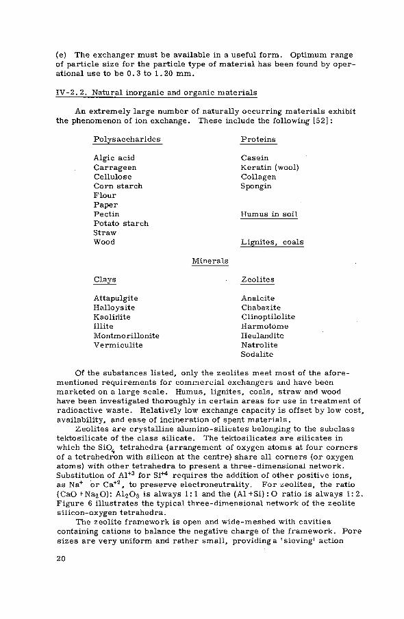
An extremely large number of naturally occurring materials exhibit the phenomenon of ion exchange. These include the following [52] :
Polysaccharides Proteins
Algic acid Carrageen Cellulose Corn starch Flour Paper Pectin Potato starch Straw Wood
Casein Keratin (wool) Collagen Spongin
Humus in soil
Lignites, coals
Minerals
Clays Zeolites
Attapulgite Halloysite Kaoliriite Illite Montmo rillonite Vermiculite
Analcite Chabazite Clinoptilolite Harmotome Heulandite Natrolite Sodalite
Of the substances listed, only the zeolites meet most of the afore-mentioned requirements for commercial exchangers and have been marketed on a large scale. Humus, lignites, coals, straw and wood have been investigated thoroughly in certain areas for use in treatment of radioactive waste. Relatively low exchange capacity is offset by low cost, availability, and ease of incineration of spent materials.
Zeolites are crystalline alumino-silicates belonging to the subclass tektosilicate of the class silicate. The tektosilicates are silicates in which the Si04 tetrahedra (arrangement of oxygen atoms at four corners of a tetrahedron with silicon at the centre) share all corners (or oxygen atoms) with other tetrahedra to present a three-dimensional network. Substitution of Al + 3 for Si+4 requires the addition of other positive ions, as Na+ or Ca + 2 , to preserve electroneutrality. For zeolites, the ratio ( C a 0 + N a 2 0 ) : A 1 2 0 3 is always 1 : 1 and the (Al +Si) : О ratio is always 1 : 2 . Figure 6 illustrates the typical three-dimensional network of the zeolite silicon-oxygen tetrahedra.
The zeolite framework is open and wide-meshed with cavities containing cations to balance the negative charge of the framework. Pore sizes are very uniform and rather small, providing a 'sieving' action
2 0

ANGSTROM UNITS
FIG.6. Types of linkage of silicon-oxygen tetrahedra. Three-dimensional network. (Reprinted from Berry, L.G., Mason, В., Mineralogy. Copyright © 1959 W.H. Freeman and Company, San Francisco, Cal., USA.)
as mobile ions are exchanged. L a r g e r ions are excluded from exchange, the maximum size being dependent upon the particular zeolite. The zeolite framework (Si, A1)0 2 is held together by strong bonds and is v e r y rigid. Water molecules can be removed without affecting the stability of the structure. The name 'zeolite ' , in fact, is derived from the Greek and means 'to boil ' , referring to the apparent boiling that occurs when these minerals are heated and the water is released.
Other natural ion-exchange minerals are those clay crystall ine aluminosilicates of the subclass 'phyllosi l icates ' , from the Greek meaning ' leaf ' o r ' s h e e t ' . In the lattice structure of these exchangers, three oxygens of each tetrahedron are shared with adjacent tetrahedra to form extended flat sheets. Si: О ratio is 2 : 5 . This type structure is common to all c lays and micas and one of the chief characterist ics of the type is the perfect basal cleavage parallel to the plane of the sheet. The sheet structure is illustrated in F i g . 7. The phyllosil icates c a r r y their mobile ions between the layers of the lattice.
The 'tetrahedral l a y e r ' , as the sheet formed by S i 0 4 tetrahedra is called, is commonly joined by other sheet- l ike groupings of cations (normally aluminium, magnesium or iron) in co-ordination with oxygen and hydroxyl ions. These other sheets are octahedral groupings of anions around a cation centre with anions shared by adjacent octahedra. When a mineral is composed of a tetrahedral l a y e r and an octahedral layer, it is c lassif ied as having a t w o - l a y e r structure, e . g . kaolinite, halloysite, antigorite. When an octahedral l a y e r is sandwiched between two tetrahedral l a y e r s , the structure is termed t h r e e - l a y e r , e . g . montmorillonite, muscovite, talc, vermicul i te . The phyllosil icates can swell m o r e than the tektosil icates but they are much l e s s resistant to mechanical b r e a k -down.
2 1

Many of the natural organic exchangers must be treated chemically to improve stability before they are of much value as ion exchangers. Treatment with solutions of certain metal salts, sodium hydroxide or hydrochloric acid has been used to stabilize coals.
7.15 д
AXIS
Ь AXIS
FIG. 7. Structure of kaolinite, Al4Si4O10(OH)8 . A tetrahedtal sheet Si4Ol0 linked to octahedral A1404(OH)8. (Reprinted from Berry. L .G. , Mason, B., Mineralogy. Copyright @ 1959 W.H. Freeman and Company, San Francisco, Cal. , USA.)
Sulphonation, however, has been found to be the most commercially im-portant treatment. Exchangers of sulphonated coal have been marketed for many years. The sulphonation treatment works well with many sub-stances, and in fact, almost any materials which will not dissolve in sulphuric acid can be made into cation exchangers.
Tables XIa and Xlb list a number of natural exchangers with some of their properties.
I V - 2 . 3 . Synthetic inorganic and organic materials
Among the f irst synthetic inorganic ion exchangers were those which resembled the zeolites. These were improved through the years until the present when the synthetic zeolites are exact counterparts of the natural minerals. Due to their ability to exclude larger molecules from their uniform pore structures, they have been termed 'molecular s i e v e s ' . Adjustment of pore size can to a certain extent be accomplished by converting the exchanger to other ionic forms. Some of the sieves avail-able commercially include:
Linde AW 400 Linde AW 500 Linde AW 300 Linde 13X Linde 4A Norton Zeolon
synthetic erionite synthetic chabazite synthetic mordenite synthetic faujasite (no natural counterpart) synthetic mordenite
22

The structure of the zeolites con-sists of a rigid three-dimensional framework of SiO, and AlO, tetrahedra.
The Type A Molecular Sieve has a framework composed of trun-cated octahedra joined in a cubic array.
This produces a central truncated cube octahedron with an internal cavity of 11 Â in diameter. Each central cavity, termed the a cage, is entered through 6 circu-lar apertures formed by a nearly regular ring of eight oxygen atoms with a free diameter of 4.2Â. The cavities are thus ar-ranged in a continuous three-dimensional pattern forming a system of unduloid-like channels with a maximum diameter of 11Â and a minimum of 4.2Â. The truncated octrahedra them-selves enclose a second set of smaller cavities 6.6Â in internal diameter (/3 cages) and con-nected to the larger cavities by means of a distorted ring oí six oxygen atoms of 2.2Â free diam-eter.
TRUNCATED OCTAHEDRON FACE OF CUBIC ARRAY
OF TRUNCATED OCTAHEDRA
Model of the s t r u c t u r e of zeolite
t y p e A based oil skeletal te trahedra.
FIG.8. Molecular sieve structure. (From Linde Molecular Sieves brochure. Reprinted by permission of Union Carbide Corp., Linde Div., New York, USA.)
23

Figure 8 illustrates the structure of the Linde sieves. In com-mercial form, they are available as micro crystalline powders, as pellets and as beads. The pellet form utilizes the microcrystals with porous clay binder material.
Many very promising ion exchangers have been prepared from zirconium phosphates. Tin, titanium and thorium compounds have shown similar promise. They are extremely insoluble, have high exchange capacities and high rates of exchange. Probable structure of a zirconium phosphate is [53]3:
O P O g = 0 P 0 3 -
I I Z r - О - Z r - О
I I O P O g = O P O g =
Materials of this type prepared to date have varied from granular precipi-tates of small particle size to dried gels of much larger particle size.
The largest group of exchangers available commercially today are the synthetic organic resins. The framework of the resins is a flexible random network of hydrocarbon chains. This framework, or matrix as it is known, carries fixed ionic charges, as -SO", -COO" in cation ex-changers and -NH3+, in anion exchangers. The resins are made in-soluble by crosslinks which interconnect the various hydrocarbon chains. Degree of crosslinking determines mesh width of the framework or matrix, swelling ability, movement of the mobile ions, hardness, and resistance to attrition and mechanical break-down. Highly crosslinked resins are harder, more resistant to attrition and break-down, less porous and swell less in solvents. Addition polymerization in the formation of the vinyl group which is included in many starting materials for present-day plastics can be shown as
C H = C H 2 C H
+ Peroxide heat
Sty rene Linear polystyrene
Copolymerization with divinylbenzene (DVB) creates the crosslinked matrix and degree of crosslinking is adjusted by varying the DVB content.
3 From HELFFERICH, F.,Ion Exchange, copyright (c) 1962 McGraw-Hill, Inc. Used by permission of McGraw-Hill Book Co.
24
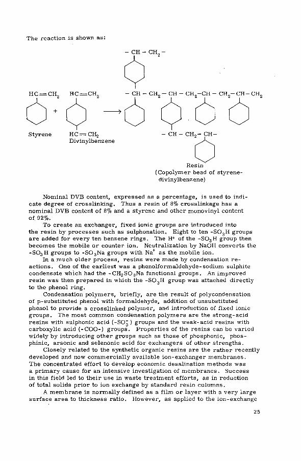
The reaction is shown as:
н е — с н 2 н с = с н 2
+
Styrene H C = C H 2
Divinylbenz ene CH - C H 9 - CH-
Resin (Copolymer bead of styrene-
divinylbenz ene)
Nominal DVB content, expressed as a percentage, is used to indi-cate degree of crosslinking. Thus a resin of 8% crosslinkage has a nominal DVB content of 8% and a styrene and other monovinyl content of 92%.
To create an exchanger, fixed ionic groups are introduced into the resin by processes such as sulphonation. Eight to ten - S 0 3 H groups are added for every ten benzene rings. The H+ of the - S 0 3 H group then becomes the mobile or counter ion. Neutralization by NaOH converts the -SO3H groups to - S 0 3 N a groups with Na+ as the mobile ion.
In a much older process, resins were made by condensation re-actions. One of the earliest was a phenolformaldehyde-sodium sulphite condensate which had the - C H 2 S 0 3 N a functional groups. An improved resin was then prepared in which the -SOgH group was attached directly to the phenol ring.
Condensation polymers, briefly, are the result of polycondensation of p-substituted phenol with formaldehyde, addition of unsubstituted phenol to provide a crosslinked polymer, and introduction of fixed ionic groups. The most common condensation polymers are the strong-acid resins with sulphonic acid (-SO3 ) groups and the weak-acid resins with carboxylic acid ( - C O O - ) groups. Properties of the resins can be varied widely by introducing other groups such as those of phosphonic, phos-phinic, arsonic and selenonic acid for exchangers of other strengths.
Closely related to the synthetic organic resins are the rather recently developed and now commercially available ion-exchanger membranes. The concentrated effort to develop economic desalination methods was a primary cause for an intensive investigation of membranes. Success in this field led to their use in waste treatment efforts, as in reduction of total solids prior to ion exchange by standard resin columns.
A membrane is normally defined as a film or layer with a very large surface area to thickness ratio. However, as applied to the ion-exchange
25

membrane, a much broader definition has been accepted. Geometrical configuration has been deleted from the definition with the remaining requirement being ion-exchange material which is used as a separation wall between two solutions. Materials including cylindrical plugs, ribbons and ion-exchange beads imbedded in binder are all used as membranes.
Ion-exchange membranes are classified as heterogeneous or homo-geneous. The heterogeneous are those consisting of colloidal ion-exchanger particles embedded in an inert organic such as polyethylene, polystyrene, polyvinyl chloride, rubber, wax, etc. Homogeneous membranes, usually in the form of discs, ribbons or sheets, are coherent ion-exchanger gels made by condensation processes. Most of the commercial membranes available are the homogeneous materials in sheet form varying in thickness from 0.09 to 0.75 mm. Cation-exchange membranes are usually in the Na+ form while the anion-exchange membranes are most often in the Cl~ form.
A new membrane which seems to fit both heterogeneous and homo-geneous classifications is the graft-copolymer type. Gamma irradiation (cobalt-60 source) of polyethylene films impregnated with styrene or styrene-DVB causes a grafting to the polyethylene base. Sulphonation or chloromethylation followed by amination produce strong-acid cation exchangers or weak-base anion exchangers.
Membranes marketed by National Aluminate Corporation are termed 'interpolymer' since they are obtained by evaporation of a solution con-taining a linear inert polymer and a linear polyelectrolyte. The film formed is insoluble in aqueous solutions even though crosslinking has not occurred.
The structure of miscellaneous other organic exchangers, as celluloses, ion-exchange papers and liquid exchangers will not be dis-cussed due to their very limited application to waste treatment.
IV-3. SYNTHESIS OF ION EXCHANGERS
The preparation or synthesis of inorganic and organic ion exchangers will be discussed very briefly since in most cases commercially avail-able materials would be used in a waste treatment facility.
I V - 3 . 1 . Inorganic ion exchangers
Many synthetic aluminosilicates have been prepared in the laboratory by crystallization at relatively high temperatures from solutions con-taining silica, alumina and alkali. Clinoptilolite-like materials have been prepared from silica, alumina and lithium hydroxide with mole ratios varying from ( S i 0 2 / A l 2 0 3 / L i 0 2 / H 2 0 ) 8/1/0. 6/8. 5 to 1 0 / 1 / 1 / 8 . 5 [54] . Temperatures ranged from 280°C to 300°C and pressures varied from 625 to 1200 lb/in2 . Zeolites analcite and mordenite are prepared with Si: Al ratios of 2:1 for analcite and 6: 1 for mordenite, both at 275°C for a period of two to three days [55] . As stated previously, synthetic zeolites of very regular crystalline structure are available commercially.
The high-capacity exchangers of the phosphate, arsenate, molybdate and tungstate salts of zirconium, titanium, tin and thorium have been pre-pared by precipitation from the chloride form. A ferrocyanide molybdate,
26

prepared by precipitation from a mixture of sodium molybdates (in HC1 solution) and H4Fe(CN)6 has a high selectivity for caesium [62] . Cerium (IV) exchangers, with properties similar to those of the zirconium salts, were prepared from a gel formed by the mixing of cerium (IV) in sulphuric acid and dilute phosphoric acid [56] . Com-mercial compounds of this type are now available from Bio-Rad Laboratories, USA, and most recently SERAI, Belgium. A number of these exchangers and their properties are listed in Table X.
I V - 3 . 2 . Organic ion exchangers
Strong-acid cation exchangers have for many years been prepared by sulphonation of coals with fuming sulphuric acid. Treatment with nitric or phosphoric acid has also been used to 'activate' the material. The coal is 'gelified' and carboxylic acid groups are formed.
Sulphonation or phosphorylation are used to convert such unlikely materials as olive pits, nut shells and spent coffee grounds to ion exchangers.
Sulphonated coals are available commercially from IMACTI, Netherlands and Jos. Crosfield, UK.
Synthesis of ion-exchange resins can be generally subdivided into condensation polymerizations and addition polymerizations. The synthesis must produce a three-dimensional crosslinked matrix of hydrocarbon chains with fixed ionic groups. The fixed ionic groups can be introduced while the polymerization is in progress or added later to the completed matrix. The finished resin must be insoluble but capable of swelling to a certain extent. This is controlled by establishing the degree of c r o s s -linking. With crosslinking varying from minimum to maximum, solubility ranges from soluble with extreme swelling to insoluble with no swelling capability.
Condensation polymerizations are those in which molecules of several different compounds combine to form a larger molecule, elimi-nating a small molecule such as H 2 0 . The phenol-formaldehyde reaction is an example. Addition polymerizations are those in which several molecules of the same or similar compounds combine to form a large molecule. These reactions also differ in that no small molecules are eliminated in the addition polymerization and the total weight of the product is the sum of the weight of all molecules used in the polymeri-zation. The unsaturated organic compounds, those containing double or triple bonds between carbon atoms, are polymerizable.
In the following discussion, synthesis of cation- and anion-exchange resins by condensation and addition reactions will be covered separately.
Tables Xa-c list commercially available cation-exchange resins and Tables XIIa-d list the anion exchangers.
I V - 3 . 2 . 1 . Condensation polymers
Cation-exchange resins. The phenol-formaldehyde condensation products, with the phenolic OH groups as the fixed ionic groups, have a very low acid strength. The simplest method to improve acid strength
27

is to introduce groups of higher acid strength as in sulphonation of the phenol prior to polymerization. Phenolsulphonic acid resins are bi-functional - both strong-acid, -S0 3 "H + , groups and weak-acid, OH, groups, are included.
When carboxylic groups, COOH, are the fixed ionic groups, weak-acid resins are formed. Synthesis involves reaction of monomers as salicylic acid and 1, 3, 5-resorcyl ic acid. The resin has the form:
When the fixed ionic groups are attached directly to aromatic rings, as in the sulphonation of phenol with H 2 S 0 4 and addition of formaldehyde, nuclear sulphonic resins were prepared. A similar resin results from the alkaline condensation of phenolate, sodium sulphite and formaldehyde. In the first case, the fixed ionic group is the "SOgNa while in the latter case, the fixed group is the methylene sulphonic acid, ( - C H S03~Na+). The CH 2 S0 3 Na resins have a slightly weaker acidity but higher thermal stability than the phenolsulphonic type.
As a general rule with condensation polymers, unsubstituted phenol or materials as resorcinol are added to enhance polymerization. A resin of the latter type is the Lewatit CNO.
Medium-acid strength condensation polymers with phosphonic acid and arsonic acid groups have recently become available. Other vari-ations include the use of the aldehyde rather than the phenolic component as the carrier, introduction of ionic groups after polymerization, pre-paration of bifunctional resins (S03H and COOH groups), and preparation of condensation polymers with a silicone framework.
Anion-exchange resins. Though several minerals (apatite, hydroxylapatite) act as anion exchangers, their use is very limited due to iow resistance to acidity. The first satisfactory materials for anion exchange were the synthetic organic resins.
As with the cation-exchange resins, condensation polymers are rapidly being replaced by the more stable addition polymers. Ionic groups on the anion exchangers are less stable than those in use in cation resins and the best anion-addition polymer does not compare well with the best cation exchanger.
Among the first anion exchangers prepared by condensation polymeri-zation was the product of condensing phenol, formaldehyde and triethylene
O H O H
2 8

tetramine whose structure is: O H
н 2 с с н 2
Н з С - С ~ С Н з
II 2 C C i l ,
- с н 2 - О - CH, "2
O H N11
C H 2 - C H 2 - NH - C H 2 - C H 2 - NH - C H 2 - C H , , - NH,¿
The resin is relatively low in cost and high in capacity.- It is a weak-base exchanger, the functional groups being the secondary ( -NH-) and the p r i m a r y (-NH 2 ) amine groups.
Another of the early resins was prepared by a condensation reaction of m-phenylenediamine with formaldehyde. The relative amount of formaldehyde used determines both degree of crosslinking and base strength. B a s e strength can be increased by condensing aliphatic polyamines rather than the aromatic amines with aldehydes. Halo-epoxides are v e r y strong condensing agents, and used with or instead of the aldehydes, provide resins with strong-base quaternary ammonium groups. A l l such resins are polyfunctional.
Condensation polymers have been prepared with ammonia or ammonium salts, and recently resins with quaternary phosphonium and tert iary sulphonium groups, of high base strengths, have been synthesized.
I V - 3 . 2. 2. Addition polymers
Cation-exchange resins. Most of the cation-exchange resins commonly used in waste treatment are addition polymers made by sulphonation of a styrene-divinylbenzene copolymer. Sulphonic acid groups are introduced after polymerization by heating with concentrated sulphuric acid or chlorosulphonic acid. C o m m e r c i a l divinylbenzene (DVB) is generally used as the crosslinking agent. Ratio of D V B to styrene is e a s i l y adjusted in the reaction and therefore control of degree of crosslinking, which in turn determines porosity, is simple. Reproduc-ible results are achieved with relative e a s e .
Nominal DVB content, as mentioned in manufacturers' l iterature, r e f e r s to mole percent of pure divinylbenzene. Commonly used resins contain 8 to 12% DVB, but for special purposes, 0.25 to 25% D V B resins have been made available. Increasing D V B content d e c r e a s e s swelling and porosity and increases toughness and mechanical stability. The opposite happens as D V B content d e c r e a s e s . Low D V B content resins swell strongly and are soft and gelatinous. Table IX demonstrates variation of moisture content and capacity with percent D V B .
2 9

This type resin, with sulphonic (SOgH) or methylene sulphonic (CH2S03H) functional groups, is of high capacity, has relatively high thermal, chemical and mechanical stability, a rapid rate of exchange and a 'salt-splitting1 ability when operating in the hydrogen cycle. By salt-splitting is meant the ability of the hydrogen form of a resin to remove cations from neutral salt solutions.
A weak-acid ion-exchange resin, with weakly ionized carboxylic acid groups, is prepared by suspension copolymerization of acrylic or methacrylic acid with DVB. The -COOH groups have little or no salt-splitting capacity but in alkaline solutions, these resins will remove cations equivalent to the alkalinity present. The resins have a strong affinity for Ca+ + and regeneration with Na+ directly is very difficult.
Intermediate-acid resins with phosphonic acid (-PO|~), functional groups, phosphonous acid ( - P 0 3 3 ) , phosphinic acid ( -HP0 2 ) and arsonic acid (-AsO|~) groups have proven of value and some, as Duolite ES-63 (phosphonic acid) are available commercially.
New resins have been prepared with very wide pores which permit access to the interior even when nonpolar solvents are used. Pores in the spherical beads provide openings several hundred  units in width. These 'macroreticular' resins are prepared by a variation of one of the addition polymerization techniques. An organic monomer solvent which will not affect the polymers is added to the polymerization mixture and as the polymerization proceeds, the growing copolymer areas emit the solvent. Rohm and Haas 'amberlyst' resins are of this type.
Anion-exchange resins. Synthesis of anion-exchange resins by the addition reaction is very similar, to a point, to preparation of the cation exchangers. Beads formed by suspension copolymerization of styrene and DVB are treated with chloromethyl ether catalyzed by aluminium chloride or zinc chloride. - C H 2 C 1 groups are introduced on the benzene rings. This product is then áminated with trimethylamine to provide a highly ionized functional group of quaternary ammonium
CH3
I - C H 2 - N+— CHg
I
C H 3
The resin is a strong-base anion exchanger and in the OH" form has the basicity of NaOH. Methylstyrene, vinylanisole and other styrene deri-vatives can be used with crosslinking agents other than DVB, such as vinylacrylate.
Strong-base resins are commercially available as Type I or Type II. When the four substituents on the nitrogen atom include a polymeric benzyl and three methyl groups, the resin is termed a Type-I resin. When one of the methyl groups is replaced by another group, as the ethanol group, the resin is termed Type II. Types I and II differ slightly in chemical stability and in affinity for the hydroxide ion relative to other anions. The Type-I resins are more chemically stable, par-ticularly in the hydroxide form, but the Type-II resins are more ef-ficiently converted to the hydroxide form.
3 0

When the chloromethylated copolymer of styrene and DVB is reacted with ammonia or with primary or secondary amines, weak-base anion exchangers with primary, secondary, and tertiary amine functional groups result.
I V - 3 . 3 . Ion-exchange membranes
Ion-exchange membranes are of two principal types, the. heterogeneous and the homogeneous. The heterogeneous, though capable of being made from almost any ion exchanger, have limitations such as lower electric conductivity and higher permeability for electrolytes. They are being replaced by homogeneous membranes as physical strength problems are resolved.
Heterogeneous membranes are prepared by dispensing colloidal or finely ground ion-exchange materials throughout a thermoplastic inert binder such as polyethylene, polystyrene or synthetic rubber. Ion-exchange particles must be in contact with one another within the binder but not to the complete exclusion of the binder and loss of mechanical strength. They therefore comprise 50 to 75% by volume of the hetero-geneous membrane. Mixtures of resin and binder are rolled, compressed or extruded to form thin ribbons, discs or film.
Homogeneous membranes are condensation products of sulphonated phenol and formaldehyde or nitrogen-containing compounds and formaldehyde. These strong-acid or strong-base condensates are laid out in thin sheets on mercury or acid-resistant plates. They can also be prepared by heating a precondensed, viscous reaction mixture between glass plates. The membranes formed are translucent. If additional mechanical strength is required, membranes are prepared by polymerization on supporting wide-mesh plastic screen or tissue.
Commercial membranes have also been prepared by 'interpolymer' and 'graft-polymerization' techniques. The interpolymer films are ob-tained by evaporation of a solution of linear polyelectrolyte and linear inert polymer. The membranes are insoluble in aqueous solutions though no crosslinking has been achieved. In the graft polymerization method, cobalt-60 gamma radiation is used to graft styrene or styrene-DVB mixtures impregnated in polyethylene film to the polyethylene base. Sulphonation of the graft copolymer produces a strong-acid cation-exchange membrane while chloromethylation and quaternization or amination provide strong-base and weak-base anion-exchange membranes. Optimum styrene content of the film ranges from 30 to 50 mole percent. Tables XlVa and XlVb list commercially available membranes.
31

V. LIMITATIONS OF ION EXCHANGERS
V - l . LIMITATIONS A P P L I C A B L E TO A L L ION EXCHANGERS
In solving chemical processing problems, existing methods are investigated and evaluated. The problem is normally well defined and the processing method providing the desired product at the lowest unit cost is selected. To evaluate the use of ion exchange for removal of radionuclides from waste solutions, the capabilities and limitations of the process must be recognized and understood. In this section, some of the limitations in the use of ion exchange will be discussed.
Certain characteristics of ion-exchange materials and the process itself limit its applicability and efficiency. These include:
(1) Leakage. Whether column, batch, or moving bed systems are used, complete removal of a specific radionuclide is not normally possible due to leakage. In a properly designed system, leakage may be very low, but improved removals would require a considerable effort at high cost per unit improvement. This leakage may be due to:
(a) radionuclides in colloidal size particulate form; (b) a portion of the radionuclide concentration, though in solution, may be in non-exchangeable or non-electrolyte form; (c) mechanical difficulties, e . g . channelling in columnar operation, which are difficult to detect and prevent.
In most cases, the amount of leakage from a well-designed system will be within acceptable limits.
(2) Radionuclides in the waste must be in an exchangeable, electrolyte form. Radioelements of some of the heavy metals have hydroxide forms of low solubility. In other instances, radionuclides in solution may be sorbed by suspended matter in the waste and thereby become non-exchangeable.
(3) The concentration of suspended solids in the waste solution must be very low. For most efficient and economical operation, the exchanger beds cannot be used for filtration as during column operation. In most cases, prefiltration will extend the length of ion-exchange cycles, extend the life of the exchanger, permit closer control of the operation, reduce leakage and permit more efficient backwashing and regeneration.
(4) The concentration of total solids in the waste solution must be rela-tively low. As reported in section III-2. 4, at high concentrations exchange potentials of ions of different valences diminish. Exchange potentials of ions of similar valence become similar or decrease with increasing atomic number. Competition for exchange sites is much greater and exchange efficiency of a specific nuclide is impaired.
32

2500 mg/l is generally accepted as a maximum total solids concentration. F o r most efficient resin use, however, total solids should be less than 1000 mg/l .
(5) Certain radioelements, as ruthenium, are very difficult to remove from solution by ion exchange because of their chemical complexity.
(6) Radionuclides which are monovalent or of low atomic number are difficult to remove by ion exchange except when exchangers specific for the element are used.
(7) In certain cases, costs may be a limiting factor in consideration of the ion-exchange process. Synthetic ion-exchange resins are relatively expensive. The cation-exchange process is normally operated in an acid phase, requiring the use of more costly acid-resistant piping and equipment.
V- 2. LIMITATIONS A P P L I C A B L E TO N A T U R A L ORGANIC EXCHANGERS
This group includes lignitic and bituminous coals and anthracites, woods, cotton, tar, nut shells, olive pits, and other materials. They are seldom used in their natural state because of instability. They will swell excessively, many will decompose in alkali, and many are mechanically weak. The coals are often stabilized with metal salts and almost all materials are sulphonated or phosphorylated to improve exchange capacity. Limitations in the use of these materials for treatment of radioactive wastes include:
(1) Low exchange capacities as compared to other available exchange materials
(2) Excessive swelling with a tendency to peptize (3) Limited radiation stability (4) Weak physical structures (5) Non-uniform structure (6) May be subject to decomposition by alkalis.
Several exchangers of this type are available commercially. They have been 'stabilized1, however, and treated chemically to overcome many of these limitations. They are normally used where close control of the electrolyte solution can be maintained. Dusarit S (IMACTI N . V . , Amsterdam), a sulphonated coal, for example, is recommended for water treatment, but is particularly suitable for purification of glucose syrups since it has properties of activated carbon.
V-3. LIMITATIONS A P P L I C A B L E TO NATURAL INORGANIC EXCHANGERS
These materials, as stated in section I, were the first to be used for ion-exchange separations. The clay minerals and the zeolites, though replaced to a large extent by synthetic exchangers, continue to be used and have been applied extensively to treatment of radioactive waste solutions. Limitations in their use include:
33

(1) Relatively low exchange capacities (2) Relatively low abrasion resistance of the zeolites (3) Relatively limited swelling of zeolites with restricted mobility of
the exchangeable ions (4) Clay minerals tend to peptize (5) The zeolites are difficult to size mechanically (6) These materials are partially decomposed by acids and alkalis (7) Many of the clays and zeolites have only limited stability in solutions
of very low silica or salt content.
Several of the naturally occurring inorganic exchange materials are treated by stabilization techniques and are available commercially, e . g . Neopermutit and Superneopermutit. With these, of course, the treatment is designed to preserve the desirable characteristics of the natural material and overcome limitations as listed above.
V - 4 . LIMITATIONS A P P L I C A B L E TO SYNTHETIC ORGANIC EXCHANGERS
Synthetic resins are the most widely used and highly developed ex-changers available. Research and development continue on a relatively large scale and new materials, new applications and new capabilities are presented at an increasing rate. Advantages in the use of resins for applicable chemical processing problems are many. However, there are limitations which include:
(1) Limited radiation stability. The effects of large doses of radiation on exchange materials have been rather thoroughly investigated. In an extensive study at Vanderbilt University, USA, Fisher and Threadgill [58] reported capacity reductions in resins subjected to a total of 109 roentgens (2X 10⁶ R/min) of X - r a y s as:
Colour, particle size and shape are also adversely affected. Similar studies by Nater at JENER, Kjeller, Norway [59], by Hall, Streat and associates of the Imperial College, London, UK, and by a number of workers at Oak Ridge, USA, have agreed on the limited stability of resins to radiation. Figures 9 and 10 illustrate several of the adverse effects. (2) Comparatively high cost. This limitation is concerned with original capital costs of resins since attrition rates are low and little resin re-placement is required. A properly operated regenerated system is rela-tively long-lived. It is also concerned with the cost of régénérant chemicals and the cost of treating the régénérant waste. Regeneration costs must be weighed against costs of resin replacement.
Resins Capacity loss (%)
Strong-acid Weak-acid Strong-base Weak-base
10 100
40 20
34
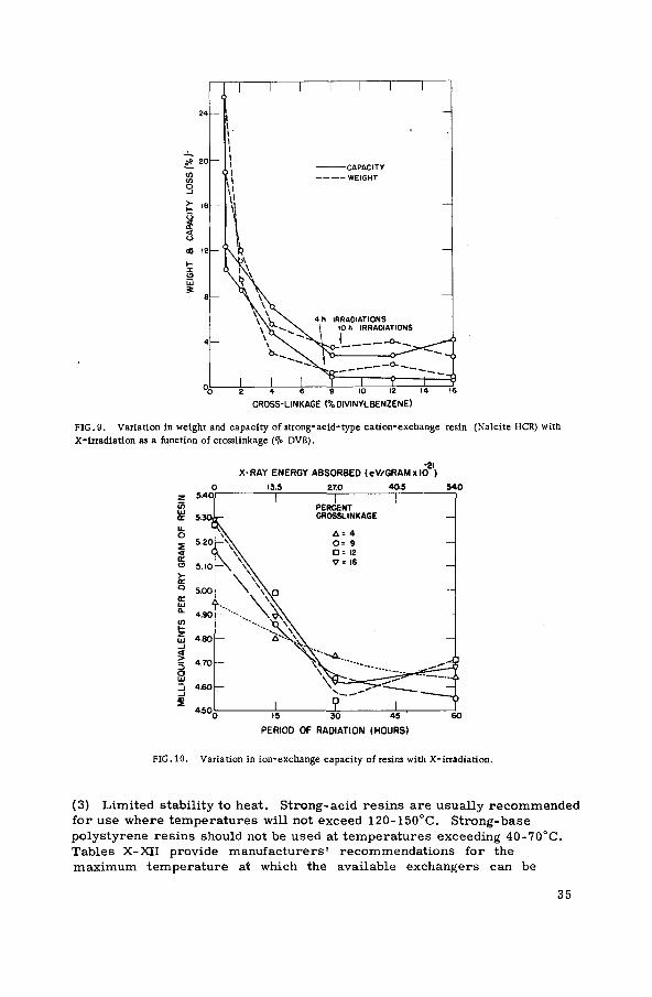
FIG. 9. Variation in weight and capacity of strong-acid-type cation-exchange resin (Nalcite HCR) with X-irradiation as a function of crosslinkage (°¡o DVB).
•21 X-RAY ENERGY ABSORBED <eV/GRAM*IO )
0 13.5 27.0 40.5 540
PERIOD OF RADIATION (HOURS)
FIG. 10. Variation in ion-exchange capacity of resins with X-irradiation.
(3) Limited stability to heat. Strong-acid resins are usually recommended for use where temperatures will not exceed 120-150°C. Strong-base polystyrene resins should not be used at temperatures exceeding 40-70°C. Tables X-XII provide manufacturers' recommendations for the maximum temperature at which the available exchangers can be
3 5

used. This limitation has restricted use of resins to treatment of low- and intermediate-level radioactive waste. Generally, wastes of these activity levels are at much lower temperatures or can be cooled below the recommended limits before treatment. (4) Increased equipment costs. Where strong-acid resins are operated in the H + cycle, acid conditions will require use of more costly materials of construction for tanks, piping, valves, etc.
V - 5 . LIMITATIONS A P P L I C A B L E TO SYNTHETIC INORGANIC EXCHANGERS
Two groups of distinctly different materials, physically and chemically, comprise this category. These are the synthetic zeolites and the inorganic chemical compounds such as the exchangers prepared by combining group-IV oxides with the more acidic oxides of groups V and VI. They will therefore be discussed separately.
V - 5 . 1 . Limitations: synthetic zeolites
The synthetic zeolites, of which a number are commercially available, are highly specific sorbents rather than ion exchangers. They act as 'molecular sieves' by excluding particles larger than the openings in the crystalline structure. The openings are adjustable for size by converting the exchanger to other ionic forms. Limitations include:
(1) Relatively high cost as compared to natural zeolites (2) Limited chemical stability in acids and bases (3) The presence of potassium in the waste solution seriously interferes with caesium removals. Studies at Hanford and Brookhaven, USA [60] demonstrated the high selectivity of the molecular sieves for caesium and strontium and their application to particular wastes. (4) Limited mechanical stability. The synthetic zeolites are exact counterparts of the natural materials with some improvement in capacity and stability.
The material Decalso (Permutit), a synthetic alumino-silicate gel and not a molecular sieve, should be included in this classification be-cause of the similar chemical composition. Its limitations, other than mechanical stability, are similar to those mentioned above.
V-5. 2. Limitations: inorganic chemical compounds
Few of these materials are presently available commercially (see Table X) due to their rather recent development. However, their out-standing characteristics - high capacity, insolubility, thermal and radi-ation stability - will hasten their development and result in wide com-mercial availability. At this stage in their acceptance, they exhibit several limitations which include:
.(1) They lose fixed ionic groups due to hydrolysis at high pH. (2) They are difficult to prepare in mechanically stable convenient size.
36

The earliest reported work with these materials was from laboratories at Oak Ridge, USA (Kraus et al.) and Harwell, UK (Amphlett et al .) . In-vestigations at the Boris Kidric Institute, Yugoslavia (Gal and Gal) and at the University of Strasbourg, France (Hure et al .) confirmed and expanded the information on them: zirconium phosphate, tungstate, molybdate; titanium phosphate, etc. In a very recent work at SERAI, Brussels, Belgium, Balon et al. [61] described the use of ABEDEM TiA (a titanium phosphate) for the separation of caesium from high-level radioactive wastes.
A number of synthetic inorganic compounds with somewhat similar properties as ion exchangers, though not utilizing the group-IV oxides, have also been studied. These include ferrocyanide molybdate as re-ported by Baetsle e t a l . [62], from work at Mol, Belgium; ammonium-12-molydophosphate as described by Smit [63], Harwell, UK, and others; potassium hexacyanocobalt II ferrate II as reported by Prout et al. [64], Savannah River, USA, and many others. These compounds, though highly selective and thermally stable, do not have the high capacity ex-hibited by the exchangers of the group-IV oxides.
V - 6 . LIMITATIONS A P P L I C A B L E TO ION-EXCHANGE MEMBRANES
Electrodialysis, the use of permselective ion-exchange membranes, is an operational process (as a pre-treatment step to conventional ion exchange) at only one waste treatment facility, the Tokai Research E s -tablishment, JAERI, Japan [65] . Use of the membranes for removal of ruthenium from waste solutions, as investigated at Battelle Northwest Laboratories, USA, has shown great promise. Limitations to the process include:
(1) Relatively high operating costs (2) In certain solutions, back-diffusion of ions may be excessive (3) Increasing concentrations of calcium and iron ions decrease cycle
length (time that a membrane system can be used before remedial action, as cleaning or replacement, is necessary)
(4) Limited mechanical stability (5) Precipitation of compounds on and in the membrane reduces cycle
length (6) High electric resistance at low electrolyte concentrations (7) Osmotic and electro-osmotic water transport.
37

VI. APPLICATION OF ION EXCHANGE
TO WASTE PROCESSING
V I - 1 . GENERAL
With the development of new ion exchangers and the advances in ion-exchange technology, the field of application of these materials in waste treatment continues to grow. Alone or in conjunction with other processes as chemical precipitation, prefiltration, electrodialysis or evaporation, ion exchange is presently in use in facilities in all parts of the world for the removal of radioactivity. The earlier serious limitations of relatively low thermal and radiation stabilities are being overcome by the new synthetic inorganic materials. A temperature of 150°C (see tables of resins) and a total of 10® R [35] will no longer restrict exchange operations as the synthetic groups-IV, - V and -VI oxides become commercially available.
Very pure nuclear grades of organic resins are manufactured for use in demineralization of reactor coolant or process water. The resins can be regenerated by remote methods, if necessary, and reused a large number of times. In many cases, storage of the spent régénérant for relatively brief periods, a matter of a few months, will permit decay of activity to levels below ICRP (International Committee on Radiological Protection) drinking water standards.
In many instances, the high selectivity of the inorganic exchangers, both natural and synthetic, is adapted to the effective processing of specific wastes. Several of these facilities successfully remove the monovalent 1 3 7 C s from waste streams, though according to the ion-exchange rules listed in section III-2. 4, this should be very difficult.
Use of the natural zeolite or clay minerals in exchange applications is possible after mechanical sizing and in some cases stabilization treat-ments, providing a relatively low-cost material. In such cases, regene-ration is unnecessary and the exhausted exchanger is treated for disposal as a contaminated solid.
Decontamination factors achieved in ion-exchange treatment of waste solutions vary in accordance with the type and composition of the waste stream, the radionuclides in the solution, type of exchanger, regeneration methods, and operational procedures. With synthetic organic resins, D F s have been reported as low as 2 and as high as 105, with the higher values in systems using dual or mixed bed (monobed) multiple stage arrangements.
Volume reduction factors (ratio of volume of solution processed to volume of residue into which the activity has been concentrated) reported vary with regard to the factors mentioned above as controlling the DF. Final disposal of the resin, the spent régénérant or the spent régénérant residues have a decided effect upon the V R F . Incineration of an exhausted organic resin enhances the VRF while neutralization of a spent régénérant solution and solidification of the mass with cement increases the volume for final disposal and causes a reduced V R F . Evaporation or distillation of the spent régénérant decreases the volume of waste for final disposal.
3 8

In this section the application of ion exchange to the removal of radioactivity from waters and principal considerations in the design of such systems will be discussed.
VI-2. PROCESSING OF REACTOR WATERS
Many of the reactors in operation today or planned for future con-struction are water cooled or water moderated. In a number of these instances, the water also serves as a shield. F o r the water to be of maximum value, it must be noncorrosive toward materials it will contact and must be free of neutron absorbing ions. This latter requirement is essential not only from the standpoint of unwanted and uncontrolled neutron capture and removal, but also from the attitude of increasing radioactivity of the system. The requirements are ideally suited to the capabilities of ion exchange, both cationic and anionic, which [66]:
(1) Can provide demineralized, neutral make-up water; (2) Can provide on-stream removal of radioactive contaminants, such as
activated corrosion products; (3) Can remove oxygen from coolant in reactor systems as necessary; (4) Can control concentration of additives such as corrosion inhibitors
and neutron poisons.
Mixed bed, dual bed and series column operation with strong-acid and strong-base organic resins are the most common methods of applying ion exchange to the problems. A number of the earliest research reactors employing ion exchange for demineralization are listed in Table II. In Table XV, some later USA power reactors and their methods of maintaining coolant purity are presented.
Make-up water for both primary and secondary loops of the Indian Point reactor originates from a municipal supply. To make it suitable for use in the reactor, it is first softened by treatment through cation-exchange resins, then treated for removal of carbon dioxide. After realkylization with caustic soda, it is evaporated and the condensate is demineralized in mixed bed exchangers. The product contains about 0.01 mg/l silica and <0.05 mg/l ionizable solids.
A s of 1962, seventeen USA, two Canadian, one Belgian, one German, one Japanese, one Puerto Rican, and one Swedish power reactor utilized ion exchange for coolant purification. In most cases, treatment on a continuous basis of only a small portion of the primary coolant of a reactor is sufficient to maintain the level of corrosion-fission products within a tolerable range. Usually this percentage can be varied within certain limits. The fission products, from recoil nuclei or from diffusion through or defects in the cladding, must be continually removed to maintain a low radiation level in external components of the reactor.
The Vallecitos Boiling Water Reactor, USA, utilizes ion exchange in the condensate return line from the turbine hot well and the Canadian NRX and NRU reactors employ mixed bed units in processing fuel rod bay water.
Reactor installations generally produce other liquid wastes, such as laboratory solutions, gas scrubber effluent, etc. and often provide separate treatment facilities. Of the reactors listed in Table XV, three
3 9

provide waste processing facilities including mixed bed ion exchangers and the fourth, at Rowe, is designed to permit use of the coolant purifi-cation resins for waste treatment.
VI-3. PROCESSING OF RADIOACTIVE WASTES
VI- 3 . 1 . General
When radioactive wastes are produced which are amenable to treat-ment by ion exchange or can readily and economically be so converted, the many diverse materials and methods of application of the process must be reviewed to determine the most suitable combination. Guidelines which emerge after a study of the exchangers available as summarized in section IV and the limitations of the process as discussed in section V include the following:
(1) Waste solutions to be processed by ion exchange should have a very low suspended solids concentration, less than 4 ppm [68], since this material will interfere with the process by coating exchanger surface and by sorbing radionuclides. Ion exchangers are too valuable to be used as filter media, and, in most cases, it will prove economical to pretreat the waste mechanically or chemically. Exceptions might include instances where low-cost natural exchangers, as the zeolites or clays, perform filtration and ion exchange on a once-through or batch treatment basis.
(2) Generally, the waste solutions should contain less than 2500 mg/1 total solids. Most of the dissolved solids would be ionized and would compete with the radionuclides for the exchange sites. Length of runs or cycles before exhaustion is therefore directly, and adversely, affected by increasing dissolved solids concentrations.
Non-ionic dissolved solids normally have little effect on synthetic organic exchangers. However, with materials which adsorb rather than exchange ions, such as the 'molecular sieves' , much of the capacity can be wasted on solutes which would be removed more economically by other means.
Exceptions would again include those cases where cost advantage would lie in the use of exchanger capacity rather than separate pretreat-ment means for removing the non-active ions. In most instances, this would involve the use of the less expensive materials, such as the natural zeolites and clays.
(3) Radioactivity associated with non-electrolytes and colloids should be very low. Most active non-electrolytes would be unaffected by the exchanger while the colloids would be filtered out, would coat the ex-changer or would also be unaffected. In any event, they would interfere with removal of the radioactive electrolyte. With this problem, an in-vestigation of pretreatment by chemical means or mechanical filtration should be made. Use of commercial or natural adsorbers or adsorbent resins should be investigated. Colloidal activity can be separated through use of adsorbers or by electrodialysis.
4 0

V I - 3 . 2 . Treatment methods: batch operation
In the event waste solutions are amenable to or can be readily con-verted to meet these specifications, two principle techniques, with variations, are available for contacting waste solution and exchanger (excluding electrodialysis). These are: (1) batch operation and (2) column operation.
The batch operation system consists of placing a given quantity of waste solution and a predetermined amount of exchanger in a vessel , mixing the components well, and permitting them to remain in contact until equilibrium is reached. The solution is then filtered off. The extent of the exchange is limited by the selectivity of the resin under the equilibrium conditions. Therefore, unless the selectivity for the radio-active ion is very favourable, the efficiency of removal will be low. Use of the batch system of operation for treatment of radioactive wastes in a currently functioning facility is unknown. An interesting application of the batch method, to illustrate its value, is the small scale sea-water-desalting units furnished in survival kits. The silver form of a strong-acid resin reacts with the sea water to remove the sodium and precipitate silver chloride, as:
RS03 Ag + Na" Cl" > RSO3 Na + Ag Cl + potable water
resin sea water resin
V I - 3 . 3 . Treatment methods: column operation
The system of column operation has a number of variations. These include:
( 1) Single column, fixed bed (a) Cation exchange only (b) Anion exchange only (c) Monobed or mixed bed
(2) Series columns, fixed bed (a) Cation-exchange columns in series (b) Anion-exchange columns in series (c) Mixed bed columns in series
(3) Dual columns, fixed bed (a) Cation-exchange column followed by anion-exchange column (b) Series columns of (a)
(4) Moving bed, continuous counter-current exchanger or pulsed bed contactor (a) Cation-exchange columns (b) Anion-exchange columns
(5) Centrifuge lined with exchanger (a) Cation exchanger (b) Anion exchanger
4 1

C o l u m n o p e r a t i o n is e s s e n t i a l l y a l a r g e n u m b e r of b a t c h o p e r a t i o n s
in s e r i e s . It is m u c h l e s s d e p e n d e n t u p o n selectivity t h a n t h e b a t c h m e t h o d
a n d t h e o r e t i c a l l y c a n b e effective r e g a r d l e s s of t h e selectivity coefficient
if sufficient r e s i n is a v a i l a b l e . C o l u m n o p e r a t i o n b e c o m e s m o r e p r a c t i c a l ,
h o w e v e r , a s t h e selectivity f o r t h e r a d i o n u c l i d e s b e c o m e s m o r e f a v o u r a b l e .
F i g u r e 11 is a s i m p l e s c h e m a t i c of a fixed b e d c o l u m n .
WASTE REGENERANT SOLUTION
ALTERNATE
EXCHANGE
AND
REGENERATION
TREATED WASTE
SPENT REGENERANT
FIG.ll. Fixed bed ion exchange, single column.
ALKALINE REGENERANT INFLUENT RINSE WATER INFLUENT BACKWASH WATER EFFLUENT RAW WATER INFLUENT
SPENT REGENERANT EFFLUENT RINSE WATER EFFLUENT
^ -t» * i
ACID REGENERANT INFLUENT RINSE WATER INFLUENT BACKWASH WATER INFLUENT DEIONIZED WATER EFFLUENT
FIG. 12. Mixed bed (monobed) i on -exchange co lumn (showing resins segregated for regeneration).
42

In many waste solutions, the radioactive ions are cations and a single column or s e r i e s of columns of cation exchanger will provide sufficient decontamination. High-capacity organic resins are often used because of their good flow rate c h a r a c t e r i s t i c s , rapid rate of exchange, stability and ease of regeneration. Other exchange materials are in use where conditions dictate their p r e f e r e n c e . Mineral exchange columns remove cations where waste volumes are low and it is m o r e economical to dis-pose of exhausted exchanger than to regenerate. The high selectivity of the synthetic inorganic materials has resulted in their selection for use where waste is predominant in a specif ic nuclide.
U s e of single or s e r i e s anion-exchange columns is v e r y limited. A c t i v i t y must be present solely in anionic f o r m . Though this is possible with elements a s iodine, sulphur, phosphorus, e t c . , it is relat ively un-usual to find waste solutions with anionic activity in the absence of the cationic.
Monobed or mixed bed columns contain both the cation and anion exchangers in the same v e s s e l as shown in F i g . 12. Synthetic organic resins of the strong-acid and strong-base type are normally used, but all combinations of strong-acid, w e a k - a c i d with s t r o n g - b a s e , w e a k - b a s e resins can be found in industrial applications. Use of m a t e r i a l s other than synthetic resins is unknown. During operation of mixed bed columns, cation and anion exchangers are intimately mixed to ensure that the acid solution formed after contact with the H + - f o r m cation resin is immediately neutralized by the O H ' - f o r m anion resin. The waste solution is therefore maintained at a neutral pH and special materials of construction are not required. This action can be shown graphically as in F i g . 13. The monobed or mixed bed s y s t e m is normally more economical for deminerali -zation of waters of low solids content than distillation. The s y s t e m yields a product extremely low in si l ica content with a specif ic resistance as high a s 20 000 000 ohm. (See Table XIII f o r c o m m e r c i a l mixed bed resins. )
CATION EXCHANGER ANION EXCHANGER
FIG. 13. Equilibria in monobed or mixed bed ion exchangers.
The principal application of the mixed bed s y s t e m in f ie lds related to the atomic energy industry is in the purification of reactor coolant as discussed previously. In many c a s e s , duplicate monobed columns are provided so that one unit is always available for s e r v i c e . General
4 3

practice is to regenerate exhausted resin, store the radioactive régénérant to permit decay of the short-lived nuclides, and discharge the very low-level waste with or into a non-active stream of dilution water.
Mixed bed systems are in use for treatment of the general radioactive waste solutions produced at atomic energy installations. In intermittent use, they have an advantage over the multiple bed systems in that ionic leakage following shutdown periods is much lower. For treatment of wastes containing mixed fission products, efficiencies obtained by the mixed bed system will be higher than those obtainable with cation-exchange resins alone due to removal of the active anions.
Dual columns, as the name implies, are merely separate columns of cation- and anion-exchange resins which are operated in series. They have an advantage over the monobed system in that regeneration is much simpler. Operation of the cation-exchange column with resin in the H+
form, however, will require use of acid-resistant materials of construction since the effluent of the column will be a dilute acid. If the anion-exchange resin is then in the OH" form, final effluent will be deionized water. Dual columns are presently in use for treatment of radioactive wastes as dis-cussed in section VII. In a number of instances, improved decontami-nation factors are obtained by serial use of the dual units. In all cases reviewed, resins have been regenerated and reused rather than destroyed.
Use of the moving bed, continuous counter-current exchanger or pulsed bed contactor system for treatment of wastes on a plant-scale basis is presently unknown. Higgins Contactors, sold by Chemical Separations Corporation, USA, are in use, however, in the Purex and Redox systems at Hanford, USA, in separation of uranium ores and other industrial applications. Figure 14 shows one of the larger industrial models. Pilot plant scale treatment of wastes by Higgins units at Oak Ridge has success-fully demonstrated the advantages of the moving bed system, which include:
(1) Constant effluent of uniform quality; (2) Smaller space requirements than other ion-exchange techniques; (3) Smaller capital investment required as compared to ion-exchange
systems of equal capacity; (4) Lower labour requirements as compared to the other ion-exchange
systems; (5) Capability of treating wastes of higher solids content.
In the moving bed system, the resin as well as the waste solution and régénérant is circulated. Wastes are treated by cation exchange, the resins are continuously regenerated and spent régénérant is continuously withdrawn. The moving bed systems are not governed by flow rate and pressure drop limitations to the degree that the fixed bed systems are. Figure 15 is a simple schematic diagram of the process.
There are at least eight variations of the continuous counter-current system which have been developed in the USA, primarily for specific industrial applications. A number are not actually continuous in that the resin does not move at all times but rather at regular short fixed intervals. The methods used to move the resin comprise one of the main areas of difference among the present systems because they are results of one of the most complex design problems in this operation (maintaining counter-current flows when resin and solution densities are only slightly different).
44

APPLICATION: HYDROGEN CYCLE WATER SOFTENING (Removal of cations. Input hardness 320 ppm Sodium: 141 ppm (expressed as CaC0}). Iron: 1.6 ppm
DIMENSIONS: Overall 10* X 10* X 30' Loading Section 84" diameter Regeneration Section 42" diameter
MATERIALS: Rubber lined Carbon Steel
CAPACITY: 2850 Gallons per minute (over 4 million gallons per day.)
FIG. 14 . C h e m i c a l Separations C o r p . m o v i n g bed c o n t a c t o r . (Reprinted by permission of C h e m i c a l Separations C o r p . , Oak Ridge, T e n n . , U S A . )
45

ELUANT
WASTE
FIG. 15. Continuous counter-current exchanger [69] .
It is l ikely that the many advantages of the moving bed will result in its much wider application in radioactive waste treatment.
A modified fixed bed column method employing the use of a centrifuge has been practiced at s e v e r a l installations. Exchanger material and type of centrifuge vary, but in the c a s e s known, exhausted exchanger is re-moved for disposal. These s y s t e m s , at Harwell, UK and Mol, Belgium, will be discussed at length in section VII.
Application of membrane electrodialysis to treatment of radioactive wastes is also in the early stage of development. It would appear from its use in desalination that it was best adapted to treatment of wastes high in dissolved or colloidal solids. In this event, its application would usually be as a pretreatment method since decontamination down to permissible levels of the lower solids waste could be accomplished by more economical means. The JAERI facil i ty, Japan, has such a system in operation. Membrane dialyzer effluents at this installation are polished to low activity levels by further treatment through mixed bed ion exchange.
Certain studies [30, 70] have concluded that the use of electrode-ionization for concentration of dilute ionic constituents, as in low-level wastes, appears feasible. No such applications are known, but the method should be considered when waste treatment s y s t e m s are contemplated.
VI-4. DESIGN CONSID ERA TIONS IN T R E A T M E N T OF RICA С TOR W A T E R S
A s discussed in section II, reactor water used as coolant, moderator and/or shielding material must be of very low ion content to minimize shielding problems from induced radioactivity. It must be noncorrosive to metals used in the reactor and it must deposit a minimum of scale in the system. The method adopted almost universally, with variations, is
4 6

demineralization by mixed bed or monobed synthetic organic ion-exchange resins. The resins used should be low in fines, with a minimum of sodium in the cation and chloride in the anion exchangers. The content of soluble organic matter in the resin must be at a very low level since it will be leached out and eventually decomposed by radiation. The products of the decomposition contribute to the attack on metal surfaces and are therefore highly objectionable. Depending upon the metals used in the reactor, the optimum pH of the water may be other than 7. 0 for minimum corrosivity. Adjustment of the pH can be accomplished through additives or through selection of the proper type of ion exchanger. Though sodium is objectionable since its unstable isotopes will create shielding problems, lithium- or ammonium-form cation exchange resins will provide basic solutions without affecting the activity of the water. If slightly acid conditions are required, a hydrogen-form cation-exchange column can be operated in parallel with the hydrogen-hydroxide mixed bed. The effluents can be blended to achieve the desired pH.
Many commercial mixed bed nuclear grade resins are available. They are specially prepared for service in reactor water treatment. They are very low in fines, and are specially treated for removal of soluble organics and inorganic impurities. The cation exchanger is available in the hydrogen, lithium, 7 L i and ammonium forms which are particularly low in sodium. The anion exchangers are available in the hydroxide form and are particularly low in chloride.
In the treatment of make-up water, mixed bed columns are used alone or in connection with other methods for ensuring a high degree of demineralization depending upon the quality of the raw water. It is generally advisable, in any case, to filter the exchanger influent and effluent.
Primary coolant water is usually demineralized in a by-pass stream. Treatment of as little as 0. 2% of the total volume being recirculated is often adequate to maintain low conductivity water. Here again, pre- and post-filtration through cartridge-type replaceable filters is recommended. In all instances, cooling of the by-pass stream is necessary if the tem-peratures exceed about 60°C, the recommended maximum for synthetic anion-exchange resins.
The ion-exchange columns can be shielded by wrapping them in lead or locating them behind shielding barriers and providing remote operation.
Several methods are in use for determining exhaustion or end of run. These include column activity, decrease of decontamination factor to a given level, and resistance or conductivity. In many cases, a combi-nation of these control methods is necessary. For service in a reactor, water must have a resistance of fifteen to twenty million ohms. Metering devices can be installed in several parts of the system (loop water, pool water, exchanger effluent) and resistance data can be transmitted to indi-cators in a remote central control area. When it has been determined that resin performance has declined to a point where fresh resin is desirable or necessary, the operating units are valved out of service and reloaded or regenerated columns function in their stead. Length of the cycle between regeneration or resin replacement is based on the design of the system and the accuracy of estimates of corrosion rates. Varying the resin volume directly varies the length of the operating cycle. Columns in the water purification system of the OWR Reactor at Los Alamos are regenerated every six weeks to three months.
47
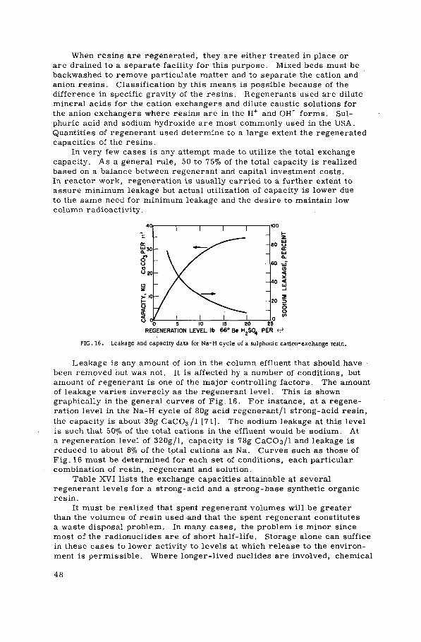
When resins are regenerated, they are either treated in place or are drained to a separate facility for this purpose. Mixed beds must be backwashed to remove particulate matter and to separate the cation and anion resins. Classif ication by this means is possible because of the difference in specific gravity of the resins. Régénérants used are dilute mineral acids for the cation exchangers and dilute caustic solutions for the anion exchangers where resins are in the H+ and OH" f o r m s . Sul-phuric acid and sodium hydroxide are most commonly used in the USA. Quantities of régénérant used determine to a large extent the regenerated capacities of the resins.
In v e r y few c a s e s is any attempt made to utilize the total exchange capacity. A s a general rule, 50 to 75% of the total capacity is realized based on a balance between régénérant and capital investment costs. In reactor work, regeneration is usually carried to a further extent to assure minimum leakage but actual utilization of capacity is lower due to the same need for minimum leakage and the desire to maintain low column radioactivity.
REGENERATION LEVEL lb 66° Be H2S0„ PER ft3
FIG. 16. Leakage and capacity data fot Na-H cycle of a sulphonic cation-exchange resin.
Leakage is any amount of ion in the column effluent that should have been removed but was not. It is affected by a number of conditions, but amount of régénérant is one of the m a j o r controlling factors. The amount of leakage v a r i e s inversely as the régénérant level . This is shown graphically in the general curves of F i g . 16. F o r instance, at a regene-ration level in the Na-H cycle of 80g acid regenerant/1 strong-acid resin, the capacity is about 39g C a C 0 3 / 1 [71]. The sodium leakage at this level is such that 50% of the total cations in the effluent would be sodium. At a regeneration level of 320g/l, capacity is 78g С а С О з / l and ieakage is reduced to about 8% of the total cations as Na. C u r v e s such as those of F i g . 16 must be determined for each set of conditions, each particular combination of resin, régénérant and solution.
Table XVI l ists the exchange capacities attainable at several régénérant l e v e l s for a strong-acid and a strong-base synthetic organic resin.
It must be realized that spent régénérant volumes will be greater than the volumes of resin used-and that the spent régénérant constitutes a waste disposal problem. In many c a s e s , the problem is minor since most of the radionuclides are of short h a l f - l i f e . Storage alone can suffice in these c a s e s to lower activity to l e v e l s at which release to the environ-ment is permissible . Where longer-l ived nuclides are involved, chemical
4 8

treatment can be used to contain the activity in a sludge which can be fixed in cement or asphalt. The spent régénérant, in other instances, is evaporated and the residues are insolubilized.
Since regeneration produces wastes of greater volume than the ex-hausted resins, it has often been found more economical to dispose of the resin rather than regenerate it. This is particularly true where the spent régénérant will not decay to low levels in a reasonable length of time and will, therefore, require treatment. Exhausted resins can be drained from specially designed columns or, if originally packaged in cartridge-type containers, can be removed and replaced as a unit. Final disposal is effected by insolutilizing the resins in cement or asphalt and packaging them l'or ground burial or sea disposal. Whore quantities and activities are low, the insolubilization step may not be required. A sig-nificant volume reduction can be achieved by incinerating the resins prior to final disposal measures.
Before discussing design of an ion-exchange column, the theory of column operation should be considered briefly. For an example, assume that it is desired to remove 1 3 7 Cs from a solution and that 1 3 7 С s is present as the electrolyte 1 3 7 C s C l . A cation exchanger in the H+ form will be used. It would seem that the exchange could be accomplished by batch methods by placing the solution in an adequate amount of exchanger and permitting sufficient contact time for equilibrium to be attained. At equilibrium, however, the 1 3 7 C s + has not been completely replaced by H . To accomplish complete replacement, an extremely large excess of ex-changer must be used or the solution must be permitted to attain equi-librium repeatedly with fresh batches of exchanger. This latter alter-native is provided in column operation. In passing through a bed of ex-changer, the solution repeatedly contacts layers of fresh exchanger. With proper flow rates and exchange depth, the 1 3 7 Cs + of the example would be completely replaced by H+ before the solution appeared at the column effluent.
When the solution is first fed to the column, replacement of 1 3 7 Cs +
by H+ takes place with the first exchanger contacted. A small zone at the influent end of the column will contain exchanger in the 1 3 7 Сs + form. A s more solution is applied, this zone expands or enlarges until it reaches the effluent end. 1 3 7 С s + is then found in the column effluent and the unit is termed 'exhausted1. At breakthrough of the 1 3 7 Cs + , the column would normally be regenerated to return the exchanger to the H+ form. This breakthrough capacity of the exchanger, the amount of 1 3 7 C s ions re-moved from solution prior to being determined in the effluent, is not the total capacity. The bottom zone of exchanger has not been completely converted to the 1 3 1 C s form. The total or overall capacity is, of course, the product of volume capacity and volume of exchanger. The ratio of breakthrough capacity to overall capacity, termed the 'degree of utili-zation', defines the fraction of exchanger volume which is effective. The following conditions or factors enhance column utilization [72]:
(a) The exchanger is highly selective for the solution counter ion; (b) The exchanger is of small and uniform particle size; (c) The exchanger has a high volume capacity; (d) The exchanger has a low degree of crosslinking; (e) The solution is at an elevated temperature;
4 9

(f ) The solution flow rate is low; (g) The concentration of counter ions in the feed solution is low; (h) The ratio of column length to diameter is high.
Certain disadvantages are inherent in a number of these conditions and they must be applied with understanding. Resins cannot withstand very high temperatures. Decrease in particle size increases resistance to flow. Low degrees of crosslinking enhance resin swelling with proba-bility of channelling. Increasing height to diameter ratios also result in increasing resistance to flow.
The regeneration phase of column operation, when adsorbed ions are eluted, must also be considered. A s the régénérant solution flows through the column, the adsorbed ions are repeatedly released from and sorbed by the resin. The concentration of these ions in the column effluent gradually increases from zero to a maximum, then decreases to zero again in an almost symmetrical pattern. The form of this curve, concentration of eluted ion vs. bed volumes of spent régénérant, is a graphic representation of regeneration conditions. Favourable conditions of flow rate and selectivity yield a relatively short, steep curve while unfavourable conditions yield a wide, squat representation.
The column may be considered as a stacked series of very short columns or 'plates'. These theoretical plates may be defined as any part of the column such that the solution leaving one end will be of the same composition as a solution which is in equilibrium with the resin of the other end. Theoretically, it is possible that minimum plate thickness would amount to the diameter of the resin particles. Actual thickness, however, due to time required to attain equilibrium, usually varies from a few millimetres to several centimetres. As time to attain equilibrium is decreased, plate thickness decreases and the number of plates per unit column length increases. Column efficiency varies directly as the number of theoretical plates per unit length.
In the mathematical approach, the number of theoretical plates re-quired to produce effluent of a desired quality is calculated on the basis of the distribution coefficient of the ion to be removed and the Gaussian curve with a maximum ordinate based on the distribution coefficient. The number of theoretical plates is directly proportional to the column height. With knowledge of the number of theoretical plates, therefore, column height can be defined.
In the application of commercial synthetic resins, it is unnecessary in most cases to calculate theoretical plate thicknesses. Loading, leakage and capacity curves are among the studies of the resins which are available from the manufacturer. A sample calculation would be as follows:
Example (1):
Problem: Removal of all ions from 1% of the primary loop coolant water.
Basic data:
(a) Coolant water circulation — 15 000 litres/min.
(b) Coolant water was originally demineralized.
5 0

(c) Cations and anions will be accumulated in the water from corrosion of metal surfaces. There will also be some suspended matter, such as insoluble hydroxides. Assume that cation concentration will be in the order of 6X 10"5 equivalents per litre in a system such as this (metals, temperatures, flow rates, pH, etc.),
(d) Temperature of loop water will exceed the maximum temperatures recommended for synthetic organic resins.
Solution:
(a) Cool the loop by-pass water to 20-25°C.
(b) Filter the cooled loop by-pass water removing all particles larger than 20 цin.
(c) Provide duplicate mixed bed ion-exchange columns with one unit for service and one unit for stand-by,
(d) Use strong-acid and strong-base synthetic organic resins, nuclear grade, with approximate total capacities of:
Cation resin — 2.0 equiv/litre Anion resin — 1.4 equiv/litre
(e) Assume the columns will be regenerated and that it is planned to utilize 85% of the total cation-resin capacity and 55% of the total anion-resin capacity.
(f) Calculate the volume of resin required:
Volume to be treated = 1% of 15 000 litres/min = 150 litres/min or (150X1440) = 216 000 litres/d
Cations removed per day = 0.00006X216 000 = .12. 96 equiv
Actual exchanger capacity = 85%X2.0 = 1 . 7 equiv/litre
L i t r e s of cation resin required for one day's operation = 12. 96/1. 7 = 7 .6
The column can be sized for any desired service (exhaustion) cycle. Assume a 20-day period is selected.
Total cation resin required = 20X7. 6 = 152 litres. In order that the mixed resins contain an equivalent of hydroxide ions for each equi-valent of hydrogen ions, the volume of anion resin required will be
1 7 , _ - - ' , , — 7 7 X 152 or 336 litres. (The cation resin has 2. 21 times (0.55X1.4) the capacity of the anion resin). Each column will therefore contain 152 litres cation resin and 336 litres anion resin.
51
(g) Check:
Optimum flow rate for columns is 0.27 litres per litre per minute (flow volume per resin volume per minute) with a normal range of 0. 2 to 0. 3. In this case, flow of 150 litres per minute into a column
150 containing 488 (152+ 336) litres of resin amounts to — — or 488
0. 31 litres per litre per minute. To satisfy the maximum value of 150 0. 3, -Q—g or 500 litres of resin would be required. It is recommended,
therefore, that total resin volume, for longer contact time and im-proved hydraulic performance, be increased to 500 litres, with 156 litres cation resin and 344 litres of anion resin. The service or exhaustion cycle will be extended to:
156 litres cation resin 7 .6 litres cation resin req'd/day
or 20.5 days.
(h) L i f e expectancy of the resins is affected by chemical degradation, physical degradation and fouling due to irreversible binding of certain ions. Many contributing factors or influences are involved, some of which can be controlled only to a limited extent. A 'rule of thumb1
value where conditions are not obviously aggressive is based on the total volume of liquid which has been treated. These values are, for
Cation-exchange resins > 667 000 litres per litre of resin
Anion-exchange resins 133 400 to 266 800 litres per litre of resin.
In the example, therefore, the cation resin should serve for pro-cessing more than (667 OOOX 156) or 104 052 000 litres, while the anion-exchange resin should treat (266 800X344) or 91 779 000 litres. With the high-purity waters involved in reactor coolant service, practice has shown that these values can. be increased by more than a factor of 10, so that the question of regeneration must be considered. If the capital investment required for the equipment necessary for pre-paring and feeding régénérant chemicals and for treating the spent régénérant solutions cannot be justified as opposed to replacing the resin, some satisfaction may be realized in being aware that the resins had served a number of normal lifetimes. In the example, it will be assumed that considerations in favour of regenerating outweighed those opposed.
(j) Consider the physical plant and operating conditions:
In addition to knowledge of the 150-litre per minute feed rate and the resin volumes, certain other basic data must be at hand to select column size. These include (a) variation in head loss with varying feed rate and solution temperature, (b) minimum resin depth and (c) space required for bed expansion in backwashing.
52

Table XVII shows variation in pressure drop per 30.48 cm of depth in a column of the sulphonic acid cation exchanger Amberlite IR-120 as the feed rate is increased.
Prior to demineralization, the primary coolant by-pass will be cooled to about 30°C. Pressure drop will be less than that indicated under 23. 9°C. Before selecting the feed rate, it would be advisable to consider the effect of minimum depth recommendations.
Where a mixed bed of strong-acid and strong-base resins is used, bed depth may be as shallow as 30 cm. Whenever one of the resins is weakly acid or weakly basic, the bed depth must be a minimum of 60 cm or only a portion of the realizable capacity will be utilized. Table XVIII lists possible bed depths.
Backwashing requires at least 50 - 75% freeboard for expansion of cation-exchange resins and 75 — 100% freeboard for expansion of anion-exchange resins. In the mixed bed systems, this amount of expansion permits separation of the resins by difference in specific gravity. The separation is necessary prior to regeneration. Mini-mum difference in specific gravity of the cation and anion resins should be 0. 1 for satisfactory separation.
Any of the columns of Table XVIII would provide satisfactory removals with the strong acid-strong liase resins of the problem. The 100-cm resin depth will be selected, however, on the bafeis of a balance of feed rate per unit area (distribution problems) vs. in-creased depth with increased pressure drop. In some cases, pressure drop will be the decisive factor if minimum depth is ob-tained. In our case, referring to Table XVII and using the figures for 23. 9°C, pressure drop will be approximately 51 g/cm 2 per 30.48 cm or a total of 167 g / c m 2 .
Provide excess space of 120%. Straight side height will therefore be 100 cm plus (1. 2X100) 120 cm or a total of 220 cm. The column will, of course, be a pressure vessel with dished heads both ends.
(k) The column should be fabricated of special stainless steel, hastelloy steel or lined boiler plate to keep corrosion products to a minimum. Linings may be plastic or rubber of such type and quality that they will be unaffected by the acid and alkali régénérant solutions. Piping and valves must also be resistant to corrosion. For this application, the resin bed should be supported by a screen of resistant metal, glass or plastic rather than gravel and sand.
(i) Operation:
(1) Carefully condition new resins as recommended by the manufacturer.
(2) Operate in the service or exhaustion cycle at 0. 2-0. 3 volumes solution per volume resin (150 1/min in example).
(3) Switch operation to the stand-by column when resistance of the water from the operating column decreases to 1 - 5 megohm-cm.
(4) Backwash the resins with deionized water to obtain 100% bed ex-pansion. The resins will separate with the heavier cation-exchange resins settling to the bottom. Drain the tank till the solution level just covers the resin.
53

, (5) Regenerate: Régénérants used will be 4% sodium hydroxide and 10% sulphuric acid. Quantities used are based on the original decision to obtain 85% of the total cation-exchange capacity. From the manu-facturers' literature, it is found that (0. 85X2) or 1 . 7 equiv/litre capacity will require 240 g of 66° Bé sulphuric acid per litre of resin or (240X152) 36.48 kg. The 0. 77 equiv/litre capacity of the anion-exchange resin will require 160 g of sodium hydroxide per litre of resin or (160X344) 55 kg. Total régénérant volumes are:
(i) A 10% solution of 66° Bé sulphuric acid contains approximately
111 g/l itre. Therefore, a total volume of 329 litres is
required. (ii) A 4% solution of NaOH contains 41. 8 g/1. Therefore, a total /55 000 \ 1 0 1 c l . t . , I ^ g lor 1316 litres is required.
Two methods of regenerating mixed beds are in use. These are the 'two-step' method in which each type exchanger is regenerated sepa-rately and the 'simultaneous' method in which both resins are regenerated at the same time. The simultaneous method sacrifices a certain amount of close control in exchange for a saving in time. In the two-step method, anion resin is regenerated first with the régénérant either permitted to pass through the cation bed or diverted through the control distributor by an upflow of deionized water through the cation resin. Rates of flow of régénérants are critical and should not exceed 0. 067 ml of régénérant per millilitre of resin per minute (67 ml per litre per minute) or (67X156) 10.45 litres per minute for the cation-exchange resin and (67X344) 23. 05 litres per minute for the anion-exchange resin.
A point to consider in establishing the regeneration technique is that upflow of régénérant in a column where service or exhaustion is downflow will minimize leakage. A band of unregenerated resin will normally be found at the downstream end of the régénérant passage, the thickness of the band depending upon the amount of régénérant used. Regenerating in a direction opposite service flow places this band at the head of the column and requires any leakage to pass through the more completely regenerated resin.
{6) Rinse: To remove excess régénérant from the column, it is rinsed with deionized water at a rate equal to the regeneration rate. When the volume of displaced solution equals one-half the volume of the resin being rinsed, the rate is doubled until one column volume of displaced rinse water has been obtained. Following rinsing of both resins, the column is drained to within 2-5 cm of the resin surface.
(7) A i r mixing: It is now necessary to remix the resins before returning the column to service. Low-pressure air, approximately 350 g / c m 2 , is introduced at the bottom of the column. Mixing is continued until thorough intermingling of cation and anion resins can be assured. This should require about 15 minutes, though a longer period would not be harmful. A note of caution should be injected here regarding
54

the air. Equipment should be provided to assure air which is oil-free ánd very low in solids.
Following air mixing, the resins should be given a final brief rinse to remove the last traces of régénérant. The column is then again ready for service.
The above is one solution to the problem. There are many more. Nuclear grade resins are relatively new and many mixed bed columns presently in service have not taken advantage of them. Generally, the problem is complicated by pH requirements, silicates, etc. and volumes for treatment are greater. Some solutions to the problem at existing operating facilities are described in section VII.
VI-5. DESIGN CONSIDERATIONS IN T R E A T M E N T OF G E N E R A L L A B O R A T O R Y AND P L A N T WASTES
Application of ion exchange and adsorption to treatment of general low- and intermediate-level radioactive waste solutions varies widely as compared to application to demineralization of reactor waters. The solutions involved differ considerably in chemical and physical character-istics between sites. Though approaches to the problems may be similar, influences such as economics, availability, site location, etc. will guide system designs to solutions which are different but yet best suited to the particular installations. Where in one instance synthetic organic resins are used, natural zeolites or clays may be found most appropriate in another locale for somewhat similar wastes.
Two primary conditions for the successful use of ion exchange, as discussed previously, are (1) low suspended solids and (2) low dissolved solids. In only exceptional cases would it be economical to use ion-exchange materials as a filter since much cheaper substances are avail-able for this purpose. Plugging by solids would also deny use of some of the exchange capacity. Dissolved solids must be low to allow use of the exchange capacity for removal of the trace amounts of radioactive ions. Where the exchange sites are occupied by the non-active ions of the sol-ution, decontamination factors will be low and the use of this method may become uneconomical. Exceptions, of course, are those cases where exchangers are readily available at low cost.
A s an illustration of the almost unlimited capacity available for treat-ment of low- and intermediate-level wastes by strong-acid synthetic organic cation exchangers, when no competing ions are present, Example (2) is presented below.
Example (2):
Assume a waste consisting of l X 1 0 _ 2 ^ C i / m l of 90Sr in otherwise demineralized water. This solution will be treated by 50 litres of a strong-acid synthetic organic resin with a breakthrough capacity of 1. 6 meq/ml of wet resin.
Total resin capacity = 1 . 6X50X10 3
= 8 X 10⁴ meq = 80 eq
55

ft 7 fi 9 80 eq of 90Sr = 80 X — ^ = 3505 g 90Sr. At 144 C i 90Sr per gram, the
50 l i tres of resin would be capable of removing (144X3505) or 504 720 C i of 90Sr before exhaustion, if it had not suffered radiation damage.
Two important considerations indicated in Table XIX are (1) the long-half - l i fe of many of these nuclides and (2) the very low permissible drinking water tolerances. Due to the slow decay, temporary storage of exhausted resins or régénérant solutions cannot be considered. The collected activity is either further concentrated by incineration of the resin, evaporation of the spent régénérant, or chemical treatment of the spent régénérant, or the exhausted resins are fixed in a slow-leaching matrix. Concentrated activity from the incineration, evaporation or chemical treatment is also insolubilized before final ground or sea disposal.
The low permissible drinking water tolerances establish the necessity for a very high degree of treatment which can be provided by ion exchange for the nuclides listed. If the waste contains only one or two or the radio-nuclides, it is possible to use an exchanger with a high selectivity for them; for example, vermiculite has been found to have a high specificity for caesium and strontium. In some instances, a cation exchanger alone will provide the required decontamination factor while in others, com-plexed ions will require treatment by both cation and anion exchange for satisfactory removal. Mixed fission product wastes of course are most successfully decontaminated by dual bed or mixed bed types of treatment. Table XX lists exchangers found to be successful in removal of specific radionuclides.
Since the waste contains 10'2 /nCi/ml or 10 mC í/1, the number of l i tres treated before exhaustion is
504 720 X 1 0 6 ^ C i = 5 0 4 7 2 0 x l 0 5 l
10 AiCi/1
= 5047X10 7 m3
In many instances pre-treatment by chemical means is justified prior to a polishing by ion exchange. In one instance, electrodeionization by membrane is the preliminary step to final treatment by ion exchange. It is often necessary to adjust the pH of the waste solution since the exchanger may not be compatible with the acid or alkaline condition of the solution or the capacity, rate of exchange, etc. may be optimum at a specific pH. The degree of treatment necessary is controlled by local conditions. The degree furnished by ion exchange can be adjusted by use of more extensive treat-ment. Single cation-or anion-exchange columns can be used in certain cases. A higher degree of treatment is afforded if the single column is replaced by similar serial columns. The dual bed and mixed bed systems afford the largest decontamination factors.
Table XIX l ists a number of the principal nuclides of concern in general waste solutions.
F o r the synthetic organic resins, operating conditions are similar to those described in discussing treatment of reactor cooling waters. Maximum temperatures and pH ranges are specified by the manufacturer. For removal of radionuclides by resin cation exchange, certain authorities [86, 87] recommend operation at a pH of 2. 5 to assure that all fission
56

products are ionized. Service flow rates are again optimum at 0. 27 litres per litre of resin per minute, but rates five times as great have been used. Resin bed depth should not be less than 60 cm. The recom-mended backwash rate is based on bed expansion which is dependent upon the resin specific gravity and régénérant temperature. F o r a 50% ex-pansion of a strong-acid polystyrene resin bed, a rate of about 4. 0 l itres per second per square metre of bed area is required. Regeneration of resins operated in the H4 cycle is accomplished with 10% HC1, 1 - 5% H2SO4 or 6N HNO3. Regeneration flow rates and rinse rates are as mentioned previously. In many cases, quantity of régénérant used is decreased by saving all but the first portion of spent régénérant for use as first régénérant in the following cycle.
The wastes at each installation must be examined individually and a laboratory study of the application of ion exchange to the treatment and disposal problems must be undertaken. It is likely that ion exchange in some form could be a major part of any waste processing installation. It is necessary to determine in which form it will be most practical and economical. Where in one case electrodeionization may be the optimum method of reducing solids in a waste, in another instance use of additional ion-exchange columns or other preliminary treatment may be more economical. Basic design computations for an ion-exchange waste treat-ment facility are identical to those shown in Example (1). Total hardness, however, would be used to determine volume of resin required. In the case of general wastes, there are more instances of resin regeneration since cycles are usually of much shorter duration.
In the treatment of the general wastes, there has been a much wider application of natural materials on a once-through basis. Capacities of the natural materials are only a fraction of those of the synthetic organic, but advantages in original cost prescribe use of the minerals, coals, etc.
Equipment requirements are fixed by the particular process selected. If alkaline conditions will prevail, iron or steel piping, valves and tanks will be adequate. Under acid conditions and for storage of acid régénérants, specific materials are necessary as follows [88]:
(a) From very dilute to 70% HNO3:
(1) 304, 316, 430 stainless steel - excellent (2) Cobalt base superalloy — no penetration at room temperature (3) Titanium — satisfactory (4) Zirconium — satisfactory (5) C F E fluorocarbon — excellent (6) Polyvinylchloride — resistant to 10, 30 and 68% acid solutions (7) Nitrile elastomer — excellent for solutions to 20% at room
temperature (8) Glass — excellent.
(b) From very dilute to 66° Bé (96%) sulphuric acid:
(1) Aluminium — satisfactory for very dilute solutions at room temperature
(2) Carbon steels — satisfactory for solutions of 90-100% acid provided there is no agitation

Cast iron (grey) — satisfactory for solutions >65% (wt) acid Cast iron (high silicon) — resistant to all conditions and tempera-tures up to the boiling point Cobalt-base superalloy — satisfactory at room temperature Copper, copper-silicon, copper-nickel — satisfactory Lead — resistant to 96% solution at room temperature Phosphor bronze — satisfactory Red brass — satisfactory Wrought iron — satisfactory at concentrations above 85% Zirconium — satisfactory Chlorinated polyether — excellent to 80% to 1 2 1 ° C , do not use for solutions > 98% Polycarbonates — no attack to 75% solution Styrene-acrylonitile — satisfactory to 30% concentration Vinylidene fluoride — satisfactory Butyl rubber — satisfactory to 50% concentration Neoprene — satisfactory to 50% concentration Nitrile elastomer — good to excellent for 17-56% at room temperature to 70°C Stoneware — excellent to 135°C Polyester coatings — no effects.
(c) From dilute to concentrated HC1:
(1) High silicon cast iron (chromium added) — resistant to dilute to 79°C; to intermediate concentrations to 66°C; to high concen-trations to 52°C Hastelloy С — resistant to all concentrations to 49°С Red brass — fair Phosphor bronze — fair Tantalum — good C F E fluorocarbon — excellent Chlorinated polyether — excellent to 50% concentration to 121 °C Ethyl cellulose — good Polyvinylchloride — resistant to concentrations to 35% Reinforced epoxy — excellent in cold Vinylid fluoride — good Butyl rubber — excellent Nitrile — excellent to 20% concentration at room temperature Polysulphide rubber — good Silicon rubber — good at dilute concentrations Glass — excellent Stoneware — resistant Glass lining — excellent at room temperatures Furane coating — no attack.
In the majority of applications of ion exchange to waste treatment, the fixed bed vertical column systems are used. The columns are com-monly operated downflow at a rate of 16 bed volumes per hour (0. 27 waste volumes per resin volume per minute) during service or exhaustion. This rate can be higher for the smaller ionic sizes, for operation at somewhat elevated temperatures, for operation of columns in series or for mixed bed systems.
5 8

Backwash is carried out upflow just prior to regeneration and at other times as it may become necessary. Backwash is used to (1) remove collected matter which may have been filtered Out during downflow, (2) eliminate any gases collected in the resin, (3) break up compressed clumps of resin caused by resin expansion and (4) reclassify resin particles as to size and position. Rate of flow during backwash must be sufficient to expand the exchanger bed a minimum of 50%. Necessary rates depend upon the exchanger density. With resins, cation exchangers are more dense than anion-exchange resins and require a higher backwash flow rate. The proper rate should be determined by laboratory methods and checked periodically to prevent washing resins to waste. Backwash waters are usually taken from stored, treated wastes, which, following the washing operation, are returned as raw waste for future treatment or are collected separately for treatment by other means.
When resins are exhausted, regeneration will immediately follow backwashing. In treatment of radioactive wastes, acids are normally used to regenerate cation exchangers and alkalis are used for anion exchangers. Optimum concentrations of régénérant solutions are obtained from the manu-facturers of commercial resins, but must be determined by laboratory methods for the non-commercial types. Quantity of régénérant used, as discussed previously, determines the capacity of the resin. The value selected is a balance of the desired capacity and length of cycles with the cost of the régénérants. With strong-acid and strong-base resins, for instance, a large excess over theoretical quantities is required to obtain a high percentage of total resin capacity. Weak-acid and weak-base resins are regenerated to hydrogen and free-base forms with little more than stoichiometric quantities of régénérants. Régénérant solutions are usually fed downflow through columns at a rate of 4-12 bed volumes per hour (0. 06-0. 2 litres per litre of resin per minute). The lower rates provide a longer period of contact, thereby allowing more complete dif-fusion of régénérant into the resin and migration of the largest ions out of the resin.
Upflow regeneration is practiced in some cases and is desirable in that leakage of strongly adsorbed ions is minimized. These ions tend to be retained in the bottom resins during the exhaustion cycle. With upflow regeneration, they are contacted first and tend to be displaced upward. The most thoroughly regenerated portion of the bed is then at the bottom of the column and leakage during the exhaustion cycle is reduced.
Use of auxiliary régénérants is sometimes necessary when organic compounds in the waste reduce efficiency of standard regeneration tech-niques. This is often combatted by washing cation exchangers with alkalis prior to acid regeneration and anion exchangers with acid solutions prior to alkaline regeneration.
Following regeneration, the ion exchangers are rinsed to remove any excess régénérant or eluted matter. Rinsing is continued until activity levels in the rinse water indicate that the exchangers are clean. Use of deionized water for rinsing is preferable since no exchange capacity will be lost to rinse water ions. However, this is not practical or economical in many cases. To compromise, a softened water can be used for rinsing cation exchangers and a 'decationized' water can serve for the anion exchangers. Minerals in rinse waters would form insoluble salts when contacting excess régénérant or ions released from alkali-regenerated
5 9

strong-base resins. Insoluble hydroxides of calcium and magnesium, for example, would coat the resins and reduce eff ic iency.
Rinsing is actually conducted in two c y c l e s . The f irst cycle at 0. 06 - 0 . 2 l i t r e s per litre of exchanger per minute s e r v e s to displace e x c e s s régénérant which is drained to the spent régénérant holding v e s s e l . The second cycle is conducted at a flow rate twice that of the f irst and the effluent rinse water is drained to waste.
Spent régénérant and f irst cycle rinse water, containing all the a c -tivity eluted f r o m the exchangers, are collected in a separate v e s s e l for further treatment. Generally used treatment methods are those which attempt to further reduce volumes. Evaporation provides maximum volume reduction, but is the most costly. Chemical treatment is possible in many c a s e s and activities are concentrated in sludges which amount to 1 - 1 0 % of original régénérant volume. In either c a s e , residues or sludges must usually be insolubilized before final disposal.
V I - 6 . SHIELDING R E Q U I R E M E N T S
The radioactivity collected in ion-exchange columns c r e a t e s a hazard to operators in the area. To permit a c c e s s to control mechanisms, the basic principles for radiation protection — time, distance and shielding — must be carefully considered in design and location of tanks, piping, controls, and appurtenances. The distance principle can be employed by locating m e t e r s , when possible, in separate rooms away from the equip-ment. F o r operating personnel, extended valve handles can be used or remote control devices can be incorporated in the design. The importance of distance cannot be overemphasized. It is usually the most easily applied principle and it is very effective. The inverse square law governs radiation intensity from point sources of gamma radiation. This law states that radiation intensity from a point varies inversely as the square of the distance f r o m the source, or:
Il_ ( D 2 )2
I 2 = ф г ) 2
where I i is the radiation intensity at distance D j and I2 is the radiation intensity at distance D2 from the source. F o r example, if gamma radiation intensity were 100 R / h at 1 m, it would be only 4R/h at 5 m.
I i d 0 0 ) _ ( P 2 )2 ( 5 2 ) 25
Ч ~ (Di) ( l 2 ) ~ 1
or I 2 = 4. Controlling exposure time is also an easily applied principle in most
c a s e s . T i m e requirements for operational functions can be minimized by proper equipment selection. Where work must be performed in high dose rate a r e a s , it can usually be completed by increasing the number of per-sonnel and limiting exposure time of each.
To reduce dose rates in working a r e a s , the principle of shielding is applied. With proper shielding materials , X - and gamma radiation are
6 0
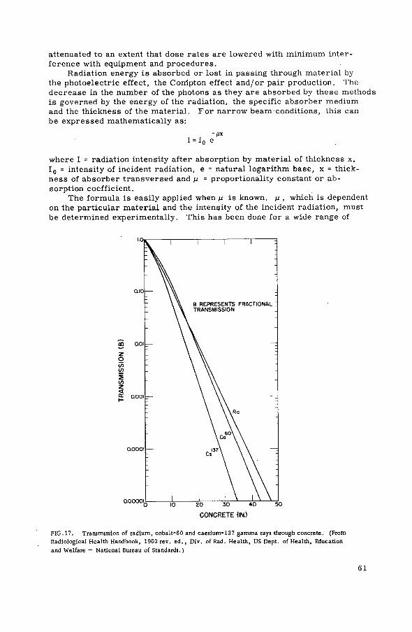
attenuated to an extent that dose rates are lowered with minimum inter-ference with equipment and procedures.
Radiation energy is absorbed or lost in passing through material by the photoelectric effect, the Corripton effect and/or pair production. The decrease in the number of the photons as they are absorbed by these methods is governed by the energy of the radiation, the specific absorber medium and the thickness of the material. For narrow beam conditions, this can be expressed mathematically as:
-ЦХ I = I 0 e
where I = radiation intensity after absorption by material of thickness x, I 0 = intensity of incident radiation, e = natural logarithm base, x = thick-ness of absorber transversed and ц = proportionality constant or ab-sorption coefficient.
The formula is easily applied when pt is known, ц , which is dependent on the particular material and the intensity of the incident radiation, must be determined experimentally. This has been done for a wide range of
FIG. 17. Transmission of radium, cobalt-60 and caesium-137 gamma rays through concrete. (From Radiological Health Handbook, 1960 rev. ed. , Div. of Rad. Health, US Dept. of Health, Education and Welfare — National Bureau of Standards.)
6 1
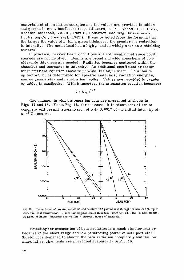
materials at all radiation energies and the values are provided in tables and graphs in many handbooks (e. g. Blizzard, E . P . , Abbott, L . S . (Eds), Reactor Handbook, Vol. Ill, Part B, Radiation Shielding, Interscience Publishing Co., New York (1962)). It can be noted from the formula that the larger the value of ц for a given thickness, the greater the reduction in intensity. The metal lead has a high ц and is widely used as a shielding material.
In practice, narrow beam conditions are not usually met since point sources are not involved. Beams are broad and wide absorbers of con-siderable thickness are needed. Radiation becomes scattered within the absorber and increases in intensity. An additional coefficient or factor must enter the equation above to provide this adjustment. This 'build-up factor', b, is determined for specific materials, radiation energies, source geometries and penetration depths. Values are provided in graphs or tables in handbooks. With b inserted, the attenuation equation becomes:
One manner in which attenuation data are presented is shown in F i g s 17 and 18. From Fig. 18, for instance, it is shown that 51 cm of concrete will permit transmission of only 0. 0017 of the initial intensity of a 1 3 7 C s source.
FIG,IS. Transmission of radium, cobalt-60 and caesium-131 gamma rays through ion and lead (B repre-sents fractional transmission.) (From Radiological Health Handbook, 1960 rev. ed . , Div. of Rad. Health, US Dept. of Health, Education and Welfare — National Bureau of Standards.)
Shielding for attenuation of beta radiation is a much simpler matter because of the short range and low penetrating power of beta particles. Shielding is designed to absorb the beta radiation completely and the low material requirements are presented graphically in Fig . 19.
6 2

FIG. 19. Penetration ability of beta radiation. (From The industrial uses of radioactive fission products, USAEC, Stanford Research Institute Report No.361.)
Where great intensities of beta radiation are absorbed, the electro-magnetic bremsstrahlung radiation is produced by the deceleration of the beta particles. The bremsstrahlung are effectively X-radiation and as such are much more penetrating than beta radiation. Shielding must be calculated using methods as for X- or gamma radiation.
Where only alpha emitters are involved, shielding as such is not usually considered. Alpha particle range is very limited. The expression R„ = 0. 312 E 3 / 2 where R а = range in cm air at 1 atm and 15°C, and E = energy in MeV demonstrates the very short range in air. Materials as paper, sheet plastic or even a coat of paint will render alpha-contami-nated surfaces harmless. The greatest cause for concern is that wind drafts over alpha-contaminated surfaces will carry the particles so that they may be inhaled. A s long as alpha contamination is controlled at the no-swipe level, dangers are minimal.
A s applied to ion-exchange practices, shielding for protection from gamma radiation is usually accomplished by wrapping units in lead sheet, by providing lead barriers or by using concrete walls of sufficient density and thickness. The distance principle is easily employed since little continuous surveillance is necessary during operation. Remotely read meters and gauges provide adequate functional control.
6 3

VII. OPERATIONAL PROCEDURES AND EXPERIENCES
VII-1. ' G E N E R A L
The many types oí ion-exchange materials and the wide variety of systems developed for using them have been discussed in the previous sections. Principal effort in this section will be directed at reviewing the known waste treatment facilities which incorporate ion exchange in any form.
Here again, demineralization of reactor coolant and radioactivity removal from general laboratory and plant waste solutions will be con-sidered separately. Treatment of reactor waters is a very specific problem which has been solved in the majority of cases in a very similar manner. Laboratory and plant waste solutions differ widely and the many problems which have been solved in whole or part by ion exchange have utilized almost the entire range of materials and methods known.
VII-2. OPERATIONAL PROCEDURES AND EXPERIENCES : T R E A T M E N T OF REACTOR WATERS
The problems in the deionization of reactor waters have been faced many times in many parts of the world. Solutions reached are the results of laboratory appraisal of the particular problems and cannot be applied at random to similar problems. However, there is much to be learned from these operating facilities in regard to design criteria. Descriptions of a number of installations follow.
(a) Consolidated Edison Thorium Reactor (CETR), Indian Point, N . Y . , USA
Type: Pressurized water power reactor
Primary coolant flow rate: 24X106 kg/h
% of total demineralized: -
Activated corrosion products: 56Mn, 5 9Fe, 1 8 2Ta, 6 0 Co, 187W
Treatment of make-up water: Raw water is softened by cation exchange, treated for removal of carbon dioxide, realkalized with caustic soda, evaporated and finally demineralized through four rubber-lined mixed bed units. The make-up water averages 0. 01 mg silica per litre and less than 0. 05 mg ionizable solids per litre.
(b) NRX and NRU Reactors, Chalk River, Ont., Canada [89]
Type: Natural uranium, heavy water moderated
Total rod bay volume: 12 000 m3
Total make-up: 850 m3/week
Make-up water: Deionized steam condensate
64

Treatment of recirculating rod bay water: Filtration and deionization through mixed bed exchangers
Type resins: Strong acid, strong base
Volume resin/col.: 0.85 m3
3 Service (exhaustion) rate: 27 0 litres per min per m . Regenerate with 6% wt HN03 and 4% wt NaOH. Evaporate spent régénérant and store residue
Controls: Conductivity maintained at 2-3 fimho-cm 1 ; beta activity <5000 disintegrations per minute per millilitre
Materials of construction: 304 stainless steel
Figure 20 is a schematic of the circulating system. The operation requires approximately 2200 man-hours of service annually.
FIG.20. Flow sheet of rod bay deionization system for Atomic Energy of Canada Ltd., NRX and NRU Reactors, Chalk River, Canada.
(c) Karlsruhe Research Reactor F R - 2
Type: Tank type, natural uranium, heavy water moderated and cooled research reactor
Coolant mass flow rate: 397 kg/s
Make-up water: Well water is filtered and deionized
Emergency cooling system: Settling tank, filter, ion-exchange columns and storage tank.
65

(d) Belgium Thermal Reactor BR-3
Type: Slightly enriched uranium, two regions, light water moderated and cooled, pressurized water type
Coolant mass flow rate: 630 kg/s
Primary coolant by-pass flow rate: 1360 kg/h Treatment by mixed bed demineralization, degasification, injection of H2 and boric acid.
Table XXI lists a number of research reactors, by country, which use ion exchange to purify reactor coolant waters. In Table XXII, water treatment systems for several of the larger power reactors are set forth.
VII-3. EXPERIENCES IN T R E A T M E N T OF G E N E R A L P L A N T AND L A B O R A T O R Y WASTES
Many operational facilities over the world use ion exchange in their processing of general plant and laboratory radioactive wastes. In most cases, it is a small part of their total capability and in many, it is merely a polishing operation. Table XXIII lists several of the major laboratories of the world with some general data regarding their utilization of ion exchange in waste processing. To cover the individual characteristics of a number of installations, they are discussed below under separate headings.
Hahn-Meitner-Institut für Kernforschung (HMI), Berlin, Federal Republic of Germany [92]
For polishing of chemically treated low-level wastes when certain nuclides, particularly 1 3 7Cs, have not been removed to satisfactory levels, ion exchange is provided. The chemical waste treatment plant effluent can be treated through cation-exchange resins, anion-exchange resins, mixed bed resins or through the three columns in series. Figure 21 is a schematic diagram of the plant.
Influent waste averages 250 mg/1 (as C a C 0 3 ) in total hardness and 400 to 500 mg/1 in total solids. Beta emitters are less than 5X 10~4 juCi/ml.
Exchangers used in the columns are strong-acid and strong-base synthetic organic resins in the Na+ and NO¿ forms. The resins are regenerated upon exhaustion and the spent régénérant is treated by evaporation. It has been possible to treat approximately 8 m3 of waste with 25 litres of cation resin and obtain decontamination factors of 102 t o l O 3 .
Materials of construction in the system include plexiglass (acrylic),-polyvinylchloride and stainless steel.
In a recent innovation, columns of a natural inorganic exchanger have been added. The columns will accept waste either prior or subsequent to chemical treatment. The low-cost material, sold commercially as 'Filtrolit', is highly selective for 1 3 7 Cs for which it has a total capacity of 22 meq/100 g. The material is heterogeneous, containing several silicate minerals. Prior to use for 1 3 7 Cs removal, it is given a NaCl
66

CHEMICAL FEED
WASTE- П WATER и v
WASTE • — SLUDGE
х -
F , T J j g T . . .
Дг j
flrtt ([ l« D г \ / / г r>
.ТО CITY " SEWERS
О 9
I. GREASE TRAP 2 HOLDING TANK 1 STORAGE TANK 4 CHEMICAL PRECIPITATION TANK й PRESSURE FILTER
6. ION-EXCHANGE COLUMNS 7 STORAGE TANK FOR ION-EXCHANGE
COLUMN RINSE WATER 8. FINAL EFFLUENT HOLDING TANK 9. WASTE PUMP 10. SLUDGE PUMP
FIG.21. Waste treatment, Hahn-Meitner Institute, Berlin.
treatment which significantly increases its capacity. Preliminary studies indicate that it will be possible to treat 40-50 m3 of waste with a column containing 25 1 of exchanger. Exhausted media will be collected in drums for final disposal as solids.
Atomic Energy Research Establishment, Harwell, Berks, UK [94]
Ion exchange for waste treatment at Harwell is still somewhat experimental. In one application, effluent of a chemical treatment plant for medium-level waste is given a final polishing through v e r m i -culite. Total dissolved solids in the feed to the exchanger vary from 500 to 200 mg/l and activity in the form of mixed fission products averages 10-1 to 10"3 /jCi/ml.
The inorganic mineral vermiculité with a specificity for 1 3 7 Cs and 90Sr is used as a lining in a vertical centrifuge. Figure 22 is a schematic of the process and Fig. 23 shows the actual equipment being used. E x -haustion is determined by breakthrough of radioactivity and exhausted mineral is discharged directly into the disposal container. Decontamina-tion factors for the exchanger are approximately 10 for alpha emitters and 20 for beta emitters. Materials of construction for the system are generally mild steel or rubber-lined mild steel.
In another application at Harwell, filtered medium-level radioactive waste is demineralized in a series of cation-anion exchange columns. Suspended solids in the column feed are <4 mg/l and dissolved solids vary from 500 to 1500 mg/l. Activity due to mixed fission products ranges from 1 to 10~3 juCi/ml.
Resins used in the cation-exchange columns are strong-acid sulphonated polystyrene and resins of the anion-exchange columns are weak-base polystyrene. Each of the four columns contains 0.38 m3 of
67
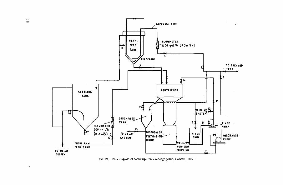
FIG.22. Flow diagram of centrifuge ion-exchange plant, Harwell, UK.

F I G . 2 3 . Centri fuge i o n - e x c h a n g e plant , Harwell , UK.
resin. Figure 24 is a schematic diagram of the facility and Fig. 25 shows the actual plant.
The plant is operated with an average feed rate of 97.2 litres min"1
m"3 through the serial cation-anion resin columns. Exhaustion is de-termined by increase in conductivity in the effluent of the fourth column. The first pair of columns is then regenerated and used as the second pair in the following run. Nitric acid, 4.4N, is used to regenerate the cation-exchange resin and 3N sodium hydroxide is used to regenerate the anion exchanger. Two bed volumes of régénérant are used, with the first bed volume being the second bed volume of régénérant from the previous cycle. The method is very effective in reducing régénérant volumes requiring further processing. After the used régénérant from the previous cycle has served for the second time, it is absorbed by exfoliated vermiculite for storage or sea disposal.
Materials of construction used include rubber-lined mild steel for the major portion of the plant and stainless steel for those units in contact with nitric acid.
69

Los Alamos Sc ien t i f ic L a b o r a t o r y , Los A lamos , N. M . , USA
The n o r m a l was te s t r e a m at Los A lamos i s p r o c e s s e d by c h e m i c a l t r e a t m e n t m e t h o d s fo r r e m o v a l of the a lpha e m i t t e r s p lu tonium and u r a n i u m . C e r t a i n of the w a s t e - c o n t r i b u t i n g f a c i l i t i e s , however , on an i r r e g u l a r schedu le , d i s c a r d so lu t ions containing r e l a t i v e l y l a r g e amoun t s of mixed f i s s ion p r o d u c t s . The r ad ionuc l ide of m a j o r c o n c e r n due to i ts c o n c e n t r a t i o n in the w a s t e s and i ts v e r y low dr inking w a t e r t o l e r a n c e i s 9 0Sr. To r e d u c e i ts l eve l in the was t e , two ion-exchange c o l u m n s have been p rov ided at the e f f luen t end of the c h e m i c a l t r e a t m e n t f ac i l i t y . P ip ing a r r a n g e m e n t s a r e such that e i t h e r u n t r e a t e d o r c h e m i c a l l y t r e a t e d was t e m a y be fed to the c o l u m n s . The uni ts a r e 1.98 m in d i a m . and conta in 4.15 m 3 of s t r o n g - a c i d p o l y s t y r e n e ca t i on -exchange r e s i n e a c h . pH of the feed solut ion i s a d j u s t e d to 2 .5 -3 .0 with n i t r i c acid and the feed r a t e i s ma in ta ined at 0.23 1 / m i n / l of r e s i n . Exhaus t ion i s d e t e r m i n e d by 90Sr b r e a k t h r o u g h .
Piping at the co lumn is a r r a n g e d to p e r m i t s e r i e s o r p a r a l l e l ope ra t i on e i t h e r upflow or downflow. Regene ra t i on , however , i s e s t a b l i s h e d a s downflow only. All piping, v a l v e s and t anks a r e s t a i n l e s s s t e e l to the point of n e u t r a l i z a t i o n of the co lumn e f f luen t .
The r e s i n s a r e r e g e n e r a t e d with 6N n i t r i c ac id upon exhaus t ion and spent r é g é n é r a n t i s co l l ec t ed in a s e p a r a t e t r e a t m e n t tank . C h e m i c a l t r e a t m e n t of the r é g é n é r a n t solut ion with s t r o n t i u m n i t r a t e , l i m e , f e r r i c su lpha te and soda a sh r e s u l t s in a s ludge containing over 99.9% of the 9 0 S r . The s ludge , a p p r o x i m a t e l y 15% of the r é g é n é r a n t vo lume, i s d r a ined to a s t o r a g e tank fo r even tua l d i s p o s a l in c e m e n t - v e r m i c u l i t e in 200-1 d r u m s . A d i a g r a m of the e n t i r e fac i l i ty i s shown in F ig . 26.
COAGULANT AID
FLOCCULATOR CLARIFIER
GRIT DRUMS TO BURIAL-
VACUUM PUMP
DEWATEREO SLUDGE TO BURIAL
CHEMICALS- SrlNO,), .nojCO, NaOH.CotOH^.FepfSlVj
GRIT CHAMBER 8 BUCKET ELEVATOR
RAW WASTE HOLDING TANKS
TREATED WASTE-HOLDING TANKS
CANYON -SLUDGE
STORAGE TANK SPENT
REGENERANT-TANK
CEMENT 8 VERMICULITE
DRUM TUMBLER:
; SLUDGE-I CEMENT DRUMS I TO BURIAL
-SPENT REGENERANT SLUDGE HOLDING TANKS
F I G . 2 6 . W a s t e t r e a t m e n t f a c i l i t y , Los A l a m o s S c i e n t i f i c L a b o r a t o r y , Los A l a m o s , N . M . , U S A .
BelgoNuc léa i r e , Mol, Belgium [96]
Ve ry s t r i ngen t r e q u i r e m e n t s l imi t ing eff luent ac t iv i ty concen t r a t i on f r o m r e s e a r c h c e n t r e s n e c e s s i t a t e the use of ion -exchange pol i sh ing of

chemical treatment plant effluent. The waste to the columns contains 500 to 1000 mg/1 total dissolved solids, beta-gamma activity of 10~5 ¿iCi/ml and alpha activity of 10"7 /uCi/ml. The very soft water, hardness 12.5 mg/1, has a pH of about 9.0.
Two columns are used in series, both containing 1 m3 of resin. The dual bed system uses a strong-acid synthetic organic resin in the Na+ form in the first column and a strong-base organic resin in the Cl" form in the second. Feed to the columns is at the rate of 0.5 litres min"1 litre of resin. Exhaustion is determined by radioactivity and hardness break-through. When this occurs, the resins are regenerated with 10% sodium chloride and the spent régénérant is directed to the low-level radioactive waste treatment plant. Decontamination factors achieved are 2 to 5 for beta-gamma emitters, 10 for 9(ÎSr and 2 to 5 for alpha emitters.
With the waste maintained at a pH of about 9.0, mild steel construction for plant equipment has proven satisfactory.
Reactor Centrum Nederland, Petten, Netherlands [97]
The ion-exchange facility included in the treatment plant at RCN is used only occasionally. When effluent of the chemical flocculation plant has over-tolerance amounts of 1 3 7 Cs, it is directed to cation-exchange columns. The two units, operating in parallel, are 64 cm in diam. and are constructed of hard-rubber lined mild steel. Exchangers are highly crosslinked strong-acid synthetic organic resins in the H* form. E x -haustion is determined by increase in column effluent beta activity. Exhausted resins are regenerated with 8% nitric acid and the spent régénérant is stored in plastic-lined 200-litre drums for future mixing with cement- vermiculite and seal burial. The decontamination factor for beta activity has averaged 100. Figure 27 is a view of the columns.
Savannah River Plant, Aiken, S . C . , USA [98]
To process evaporator overheads and miscellaneous wastes with 1 3 7 Cs concentrations at 0.05 to 0.10 /uCi/ml, the Savannah River Plant utilizes a synthetic chabazite, Linde AW-500. The material is highly selective for 1 3 7 Cs and has a total cation-exchange capacity of 2.2 meq/g.
Total dissolved solids in the overheads are usually less than 100 mg/1 but solids in the miscellaneous wastes reach 10 000 mg/1. Feed rate to the column varies from 0.13 to 0.16 litres m i n - 1 l itre" 1 of exchanger for the miscellaneous waste.
The stainless-steel columns contain 265 litres of exchanger which is utilized until 1 3 7 C s activity in the effluent reaches 1500 disintegrations per minute per millilitre. The material is then discharged to a storage tank and the column is refilled with fresh zeolite. The decontamination factor for 1 3 7Cs is usually between 100 and 200 but a maximum of 350 has been attained. A column of exchanger will adequately treat 3000 to 10 000 bed volumes of overheads or 1000 to 1500 bed volumes of the miscellaneous waste before breakthrough.
Tokai Research Establishment, JAERI, Tokai-Mura, Japan [99]
Wastes containing 640 mg/1 total solids, 500 mg/1 dissolved solids and 1.8 X10" 4 ^Ci/ml radioactivity are treated by sand filtration in the
73

F I G . 2 7 . I o n - e x c h a n g e c o l u m n s , rad ioact ive waste treatment f a c i l i t y , RCN, Petten, Netherlands.
FLOWMETER M TO
EVAPORATOR
MEASURING TANKS
i ^ J — D I S C H A R G E
F I G . 2 8 . Flow d i a g r a m o f l o w - l e v e l was te t r e a t m e n t , JAERI , T o k a i - M u r a , J a p a n .
74

first step of the low-level waste treatment process. Dissolved solids concentration is then reduced by passage through a Selemion ion-exchange membrane of 700 l/h capacity. Membrane effluent is demineralized by mixed bed ion-exchange resins to provide an overall decontamination factor of 450.
The mixed bed resins are strong-acid and strong-base synthetic organic materials operating in the H+ and Cl" forms. Feed rate to the columns is maintained at about 0.128 litres min" 1 litre" 1 resin. Figure 28 is a schematic view of the installation.
FIG.29. Ion-exchange columns (evaporator in background), JAERI, Tokai -Mura , Japan.
Exhaustion is indicated by an increase in resistivity to 1 X 10⁶ ohm-cm. Resins are regenerated with 2N HC1 for the cation and 2N NaOH for the anion; spent régénérant solutions are collected and treated by evaporation. The plant, as shown in Fig. 29, has removed 180 mCi of activity from low-level waste in a recent six-year period.
Rubber-lined mild steel is used where acid conditions require additional protection.
75

VII-4. T R A N S P O R T OF RADIOACTIVE MATERIALS
In treatment of radioactive wastes by ion exchange, it may become necessary to transport contaminated materials to other locations for further processing or for final disposal. These materials might include:
Exhausted exchangers Spent régénérant solutions Spent régénérant sludges Incinerated resin ash Evaporator spent régénérant residue.
Locally and nationally established regulations for the safe transport of these materials on land, water or in the air must be known and complied with. Internationally, the problems involved have been taken under consideration by Member States of the International Atomic Energy Agency and a set of regulations has been published. The text. Safety Series No. 6, is entitled "Regulations for the Safe Transport of Radio-active Materials". Much of what follows has been excerpted from this text.
For purposes of control, radionuclides are classified into eight groups. Table XXIV lists groups into which the main nuclides of concern in waste treatment are placed.
The regulations define large sources as those single packages containing activities greater than:
Group I 20 Ci Group II 20 Ci Group III 200 Ci Group IV - 200 Ci
Low specific activity material is that in which activity is uniformly distributed and estimated per gram concentration does not exceed:
Group I - 0.001 mCi Group II - 0.005 mCi Group III - 0.3 mCi Group IV - 0.3 mCi
Packaging design is divided into Types A and B, with Type В used for higher activity levels in certain cases and also where there is danger of submersion in water to depths to 15 m. Packages are to be coloured, labelled and marked. Category I, white packaging, is to be used when radiation from the package does not exceed 0.5 mR/h or equivalent at any point on the external surface at any time during transport. Categories II, yellow, and III, yellow, are for increasing levels of external radiation with the maximum for Category III as 200 mR/h on the external surface and 10 mR/h at 1 m from the centre of the package.
A large number of special regulations govern transport of fissile materials. Packages of these materials are further classified as Fissile Class I, Fissi le Class II and Fissile Class III. Fissi le C l a s s - I packages are nuclearly safe in any number or arrangement; Fissile
76

Class II are nuclearly safe in limited number in any arrangement; and Fissi le Class III are nuclearly safe in special arrangements.
The regulations clearly set forth testing procedures for the various types of packages. Tests listed include:
Water spray test with impact The free drop test Compression test Penetration test Thermal test Immersion test Contents leakage test Radiation leakage test.
The test name implies the conditions to which the package is subjected. Packages must be designed to prevent loss or dispersal of contents
and to retain the efficiency of their radiation shielding properties under varying conditions of handling.
The above summary is only of sufficient length to indicate the complexity of transport control. The pertinent detailed regulations -international, national and/or local - must be consulted when considering removal of radioactive materials from one area to any other.
77

VIII. COSTS OF TREATMENT BY ION EXCHANGE
VIII-1. G E N E R A L
A large number of variables are involved in comparing costs of use of ion exchange for waste treatment among various sites. In addition to the normal variables such as differences in wage rates and costs of materials, few facilities are identical in their manner of employing ion exchange, the extent to which it is employed or the type of solution being processed. In many facilities ion exchange is established as a polishing operation to be used when effluent activities have not been reduced suf-ficiently by other means. Separate accounting of ion-exchange costs in a number of these instances is not maintained and figures listed are estimates.
In this section, costs as provided by operating facilities will be reported with an attempt made to break the costs down into components as determined by a recent IAEA panel. Briefly, the operating cost estimate for ion exchange should include the following:
(a) Labour - Actual cost including benefits (b) Chemicals — Cost of exchanger and régénérant chemicals (c) Utilities, services - Costs of steam, gas, electricity, plus the
costs of services specifically assigned to the ion-exchange operation (d) Current maintenance - Cost of maintaining the ion-exchange
facility in good repair (e) Direct or operating overheads - Costs of supervisor, secretarial
and clerical staff, insurance, travel, etc. (f) Depreciation - The annual charge for amortization based on 20-yr
building life and 7|-yr equipment life (g) Total costs - The sum of the above. This total will not include
cost of general overheads or applied research.
In the case of ion exchange demineralization of reactor waters, costs of materials, services, utilities, maintenance, etc. are fairly well defined. Total costs include the expenses involved in deminerali-zation plus the expense of regeneration, if used. Where resins are not regenerated, total costs will include disposal of spent resins.
In treatment of general radioactive wastes, allocation of costs is often complicated by use of extensive pretreatment methods such as chemical coagulation. It is questionable whether any of the pretreatment cost should be charged against the ion-exchange facility. A question also exists where spent régénérant is treated by evaporation in a unit for which the régénérant is but a small fraction of its feed. In the case of pretreatment, the argument for costing the additional process sepa-rately may be justified due to activity removals obtained. Spent régéné-rant treatment, however, is related directly to the ion-exchange process and provides no additonal activity removal. Where the spent régénérant is a major portion of the feed of an evaporator, the proportional part of the cost of the subsequent process must be charged against ion exchange.
7 8

VIII-2. C A P I T A L COSTS
In the capital cost items are included building and equipment costs. As a guide in the selection of construction materials for process equip-ment, Table XXV presents current (October 1966, USA) costs of some of the metals, plastics and elastomers which might be used in an ion-exchange facility.
In Fig. 30, the comparative costs of vertical storage tanks constructed of a number of these materials are presented. The curves indicate the increase in cost for increasing capacity. Though most ion-exchange columns are pressure vessels in size ranges under 30 m 3 , the compara-tive costs shown would be similar.
i г 3 4 5 ю CAMCITY-THOUSAND GALS
1. CARBON S T E E L 2. RUBBER L INES 3. ALUMINUM 4. LEAD L INED 5. 304 STA INLESS 6. 316 STAINLESS
7. GLASS L INED 8. M 0 N E L 9. INCONEL 10 F IBERGLASS, ERECTED I I. F IBERGLASS, J O B S ITE
F I G . 3 0 . Comparative costs of vertical storage tanks.
The variables are extremely numerous but mention of the range of investments in existing ion-exchange facilities may prove of assistance in preliminary estimating for contemplated installations.
Example (1) [92]:
The installed equipment cost of the 25-1 mineral exchanger column at the Hahn-Meitner Institute, Berlin, was US$5 000. Equipment for the synthetic organic resins columns, dual bed units with 25 and 50 1 of resin in cation-anion units respectively, had an installed cost of US $6 000.
Example (2) [94]:
The dual bed columns of synthetic organic resins at Harwell, four separate columns with0.38m3 resin in each, had an installed cost of £13 500 (about US$37 800). The 149-m2 building housing the ion-exchange
79

and filtration plant cost £3200(about US $8960). Equipment for pre-filtration of waste solutions was obtained and installed for £2200 (about US $6160).
To treat the chemical plant effluent with 0.051 m3 vermiculite in the vertical centrifuge, building and equipment were provided at a cost of £8000 (about US$22 400).
Example (3) [99]:
At the Tokai Research Establishment, JAERI, electrodialysis pre-treatment followed by mixed bed ion exchange with 130 litres of strong-acid synthetic resins is accomplished in a facility for which building and installed equipment costs totalled US $79 300.
Example (4):
Two cation-resin-exchange columns, each containing 4.15 m 3 of strong-acid synthetic organic resin, and all appurtenant equipment were provided at the Los Alamos Scientific Laboratory for a cost of about US$72 000. This figure does not include any of the cost of the building housing the ion-exchange material.
Example (5) [98]:
Cation-exchange columns at the Savannah River plant, containing 265 litres of synthetic inorganic exchanger, were provided for a total building and installed equipment cost of US$75 000.
VIII-3. OPERATING COSTS
Among the many variables affecting the operating cost of ion-exchange treatment per unit volume of waste is the extent of the use of the facility. Columns at the Hahn-Meitner Institute and at the Los Alamos Scientific Laboratory are in use less than 5% of the time. It is estimated that the Harwell vermiculite-lined centrifuge will be in operation about 15% of the normal working hours. Many of the utility costs, service charges, the overhead and the depreciation are charged against a facility whether or not it is in use. To obtain reasonably accurate information on ope-rating costs, large numbers of installations operating at varying percen-tages of total capacity and utilizing the various ion-exchange methods must provide their cost data. Existing sites using ion exchange for general waste treatment are yet very limited and in many, charges to ion exchange are not separated from overall waste treatment expenses. Table XXVI lists unit cost data for several sites which vary widely in their application of ion exchange to waste processing.
In a paper presented at the Symposium on Practices in the Treatment of Low- and Intermediate-Level Radioactive Wastes, IAEA, Vienna(1965), B. Gaudernack and J. E. Lundby of Kjeller, Norway, reported a cost of US$17/m3 of low-level waste. The cost, however, ,included régénérant evaporation and solidification. In this system, strong-acid and strong-base resins were used to treat approximately 360 m3 of waste per year.
8 0

Table XXVII provides an itemized list of operating expenses at several installations.
An engineering study by Hiester et al. [100], published in 1954, provided calculated costs for full-time usage of ion-exchange processes in which radioactive materials are handled. Using an estimated 36% increase to bring costs to levels of today, their paper determined costs of US $1.07 to US $11. 50/m3 depending upon the volume processed. This range agrees well with the reported costs. It would be extended upward in cases of part-time usage of the facility.
In a recent article by Downing [101], an equation is presented for calculating total operating cost. By solving the equation with a number of assumed values for the variables, the size of an ion-exchange unit which will provide the most economical operation can be determined. Optimum regeneration levels and resin volumes can also be obtained by use of the equation. The terms used, after conversion to the metric system, are4:
A c * • Resin cost, US $/litre A d * • Resin depreciation cost, US$/yr A r - Resin depreciation time, yr A v - Resin volume, litres
A x - Resin capacity, average overall life of resin in equivalents l i t r e - 1 c y c l e - 1
E c * - Equipment cost, US $
Ed • - Equipment depreciation cost, US $/yr E t • - Equipment depreciation time, yr
Ik " - Influent ion concentration, equivalents per litre
In • - Volume water treated per cycle, litres
Iv * - Effluent requirements, litres/day L c • - Labour cost, US $ / y r Lr • - Labour rate, US $/h
ч • Labour time, h/cycle N - Number of cycles/yr R 1 * - Regeneration level, kg l i tre" 1 c y c l e " !
R c • - Regeneration cost per year, US $
r p • - Regeneration requirements/yr, kg
Rr • - Régénérant cost, US $/kg o c • - Total operating cost, US$/yr
The total cost, O c , comprises four major items — regeneration cost, resin depreciation cost, equipment depreciation cost and labour cost. In equation form, then:
O c = R c + A d + Ed + L c
4 Equations and Fig. 31 reprinted with permission from Chemical Engineering,Dec. 6,1965. Copyright (c) 1965, McGraw-Hill, Inc.

Values for each of these t e r m s are derived as follows:
l i t r e s ^ _ . f equiv \ A " (litres) М т ^ г ) X Ik fequiv^ 11 V cycle / x V litre cycle J V l't e У
T = A X A v
Ik
/ l U r e s \ Х 3 6 5 ^ Х 1 V y r / V day ) y r j / l i tres\
n\ cycle /
_ 365 Iv = 365 I v
N = 3 6 5 4 h A x A v
- ( ш ^ Г е ) X Av (Htres) X N
= R! A v N
„ _ 365 Ri I v Ik R p = r x
R c ( ^ > RP ( f ) = R p R l
(a) r = 365 R r R, Iv I„
(c)
A x
(b) A¿ m -
A T ( l l t reB)XA c( jgÍ) A y A c
A r (yr) A t
E Л ® $ \ E . ( U S $ ) „ E ^
\ У r j ~ E r (yr) " E t
US$
Уг = Gssr) x ( T ) L c = N L t L ,
(d) L c = 365 Iy Ik Lt L r
A x A v
8 2

Thus, total cost is obtained by combining (a), (b), (c) and (d) above to obtain:
O c = R c + Ad + Ed + L, с
365 R r R , I v I w A v A r + Ер + 365 I v I k L t L :r
= 365 I v I k
X
E
For comparing installations with identical equipment, the equipment depreciation term can be omitted and the equation is simplified to:
In many cases, values for Iv and Ik will be known. Values for Rr
L t and L r will be known or can be estimated to a fair degree of accuracy. Through use of the formula, operating costs can then be calculated for several selected values of:
Rr - regeneration level
Ay and A c - resin volume and resin cost
A t - assumed resin life
A x - average resin capacity
940
920
TOO, 0 2 4 6 8 10 12 14 16 1в 20 22 BED VOLUME, «Э (Atf)
FIG. 31. Operating cost vs. bed volume at various regeneration levels.
Plotting cost vs. volume curves, with a separate curve for each regeneration level, will yield a graphical representation of conditions providing minimum total operating cost. Typical curves from solution of the equation for a particular problem are shown in Fig. 31. It can be seen that optimum volume for the unit is 6 f t 3 , regenerated at 8 lb/ft 3 .
84

APPENDIX II
PRODUCERS OF EXCHANGE MATERIALS
American Machine & Foundry C o . , USA Asahi Chemical Industry Co. Ltd., Japan Asahi Glass Co. Ltd., Japan Bio-Rad Laboratories, Richmond, Calif . , USA Chem. Fabrik Budenheim, Federal Republic of Germany Chemické závody ustin labem, CSSR Chemicky kombinát záluáíu mostu, CSSR Crosfield, Jos., and Sons Ltd., London, UK Davison Chemical Div., W.R. Grace & Co. , Baltimore, Md., USA Diamond Alkali Company, Redwood City, Calif. , USA Dow Chemical Company, Midland, Mich., USA Farbenfabriken Bayer AG, Leverkusen, Federal Republic of Germany Gosud. Institut Prikladnoi Khimii, USSR Industrieele Maatschappij Activit N. V. (IMACTI), Amsterdam, Netherlands Institut vysokomol. soedin. AN, USSR Ionac Chemical Company (Division of Pfaudler Permutit, Inc.), Birmingham, N. J . , USA Ionics Inc., Cambridge, Mass., USA Japan Organo Co. Ltd., Tokyo, Japan Linde Division, Union Carbide Corp., New York, N . Y . , USA Mitsubishi Chemical Industries Ltd., Tokyo, Japan Montecatini, Milan, Italy Moskovsk. chem. technol. inst. im. Mendeleeva, USSR MUKY, Budapest, Hungary Nalco Chemical Company, Chicago, 111.. USA Nauchno-issled. inst. plast, mass., USSR Norton Company, Worcester, Mass., USA Permutit Co. (Div. of Pfaudler Permutit),Paramus, N . J . , USA Prosim, France Rohm and Haas Company, Philadelphia, Penn., USA Société d'études, de recherches et d'applications pour l'industrie (SERAI), Brussels, Belgium Spolek pro chemickou a hutnf vyrobu ustf n. labem, CSSR VEB Farbenfabrik Wolfen, German Democratic Republic VJfzkumny ústav synthetickych pryskyfic a lakû, Pardubice, CSSR Zerolit Ltd.. UK

APPENDIX II
CONVERSIONS
(a) CONVERSION TABLES
To convert from
ÂngstrBm units AngstrBm units Angstr'dm units
To
Centimetres Inches Microns
Multiply by
1X10"8
3 . 9 3 7 X 1 0 " 9
0. 0001
Atmospheres Atmospheres Atmospheres Atmospheres Atmospheres
Centimetres of Hg (0°C) Centimetres of H 2 0 (4°C) Feet of H 2 0 (39. 2°F) Grams per square centimetre Pounds per square inch
76 1033.26 33. 8995 1033.23 14. 696
Bed volumes per hour Bed volumes per minute
Gallons per minute per cubic foot Gallons per minute per cubic foot
0.1247 7.481
Centimetres Centimetres Centimetres Centimetres
Angstrbm units Inches Microns Mils
1 x 1 0 e
0. 3937 10 000 393. 7
Centimetres per second Feet per second 0.032808
Cubic centimetres Cubic centimetres Cubic centimetres Cubic centimetres
Cubic inches Gallons (Brit. ) Gallons (US, liq. ) Millilitres
0,01Л024 0.000220
0. 000264 0.999972
Cubic feet Cubic feet Cubic feet
Gallons (Brit. ) Gallons (US, liq. ) Litres
6. 22884 7.48052 28.31605
Cubic metres Cubic metres Cubic metres Cubic metres Cubic metres
Cubic feet (US) Cubic yards (US) Gallons (Brit. ) Gallons (US, l i q . ) Litres
35. 3147 1. 3080 219.9694 264.1721 999.972
Curie Disintegrations per second 3 . 7 Х Ю 1 0
Equivalents per litre
86
Kilograins per cubic foot as C a C 0 3 21.85

To convert from T o Multiply by
Feet (US) Centimetres 30 .48 Feet (US) Inches 12 Feet (US) Metres 0 .3048
Gallons (Brit. ) Gallons (Brit, ) Gallons (Brit. )
Cubic feet Gallons (US, liq. ) Litres
0 .16054 1 .20095 4 .54596
Gallons (US, liq. ) Gallons (US, liq. ) Gallons (US, liq. )
Cubic feet Gallons (Brit.) Litres
0 .13368 0. 83267 3. 7853
Gallons (Brit. ) per minute Cubic centimetres per second 75.76812
Gallons (US) per minute Gallons (US) per minute Gallons (US) per minute
Cubic centimetres per second Cubic feet per second Litres per second
63.090197 0.002228
0. 063088
Gallons per minute per cubic foot Bed volumes per hour 8. 02 Gallons per minute per cubic foot Litres per hour per litre 8. 02 Gallons per minute per cubic foot Bed volumes per minute 0. 1336 Gallons per minute per cubic foot Litres per minute per litre 0. 1336
Gallons per minute per square foot Millilitres per minute per square centimetre 4. 074
Grains Grains
Grams Pounds (avoirdupois)
0. 064799 0. 0022857
Grains per cubic foot as CaCOs Equivalent per litre 4 . 5 7 3 x 1 0 "
Grains per gallon (Brit. ) Grains per gallon (Brit.)
Grams per litre Parts per million
0 .014254 14.25418
Grains per gallon (US) Grains per gallon (US)
Grams per litre Parts per million
0.017118 17.1185
Grains per gallon as C a C 0 3 Normality 3 . 4 2 X 1 0 "
Grams Grams
Grains Pounds (avoirdupois)
15. 43236 0. 002205
Grams per cubic centimetre Grams per cubic centimetrc Grams per cubic ccntiinctre
Pounds per cubic foot Pounds per gallon (Brit. ) Pounds per gallon (US)
42.42796 10. 02241 8. 34540
8 7

To convert from To Multiply by
Grams per litre Grains per gallon (US) 58.41620 Grams per litre Parts per million 1000 Grams per litre Pounds per cubic foot 0 .06243
Grams per square centimetre Centimetres of Hg (°0C) 0 .07356 Grams per square centimetre Centimetres of H гО (4°C) 1.00003 Grams per square centimetre Feet of H 2 0 (60°F) 0 .03284 Grams per square centimetre Inches of Hg (32°F) 0.02896 Grams per square centimetre Pounds per square foot 2.04816 Grams per square centimetre Pounds per square inch 0.01422
Inches (US) Centimetres 2 . 5 4 Inches (US) Feet 0.08333 Inches (US) Mils 1000
Kilograins per cubic foot as CaC0 3 Equivalents/litre 0 .0458
Kilograms Grains 15432. 35Í Kilograms Grams 1000 Kilograms Ounces (avoirdupois) 35.27396 Kilograms Pounds (avoirdupois) 2 .20462
Kilograms per cubic metre Gram per cubic centimetre 0 .001 Kilograms per cubic metre Pounds per cubic foot 0. 06243 Kilograms per cubic metre Pounds per gallon (US, l i q . ) 0.008345
Kilograms per square centimetre Atmospheres 0 .96784 Kilograms per square centimetre Centimetres of Hg (0°C) 73.5559 Kilograms per square centimetre Pounds per square foot 2048 .161 '
Kilolitres Kilolitres Kilolitres Kilolitres Kilolitres
Cubic feet Cubic inches Cubic yards Gallons (Brit.) Gallons (US, liq. )
35.31566 61.02545 1.30799 219.9755 264.1794
Litres Litres Litres Litres Litres
Cubic centimetres Cubic feet Cubic inches Gallons (Brit. ) Gallons (US, l i q . )
1000.028 0.03532 61.02545 0.21998 0 .26418
Litres per hour Litres pet hour per litre
Gallons (US) per hour Gallons per minute per cubic foot
0.26418 0.1247
litres per minute Litres per minute
Cubic feet per minute Gallons (US, liq. ) per minute
0 .03532 0.26418
8 8
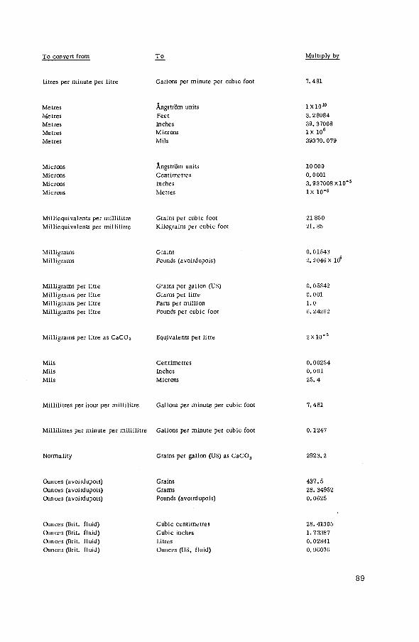
To convert from To Multiply by
Litres per minute per litre Gallons per minute per cubic foot 7 .481
Metres Metres Metres Metres Metres
Ângstrûm units Feet Inches Microns Mils
1X10 1 0
3.28084
39. 37008
I X 1 06
39370.079
Microns Microns Microns Microns
Angstrom units Centimetres Inches Metres
10 000 0.0001 3.937008 X10"5
IX 10"6
Milliequivalents per millilitre Milliequivalents per millilitre
Grains per cubic foot Kilograins per cubic foot
21 850
21. 85
Milligrams Milligrams
Grains Pounds (avoirdupois)
0.01543
2.2 046 x 106
Milligrams per litre Milligrams per litre Milligrams per litre Milligrams per litre
Grains per gallon (US) Grams per litre Parts per million Pounds per cubic foot
0 .05842 0.001 1.0 6.24262
Milligrams per litre as СаСОз Equivalents per litre 2 X 1 0 "
Mils Mils Mils
Centimetres Inches Microns
0.00254
0.001 25.4
Millilitres per hour per millilitre Gallons per minute per cubic foot 7.481
Millilitres per minute per millilitre Gallons per minute per cubic foot 0.1247
Normality Grains per gallon (US) as CaCOa 2923.2
Ounces (avoirdupois) Ounces (avoirdupois) Ounces (avoirdupois)
Grains Grams Pounds (avoirdupois)
437.5
28. 34952
0.0625
Ounces (Brit, fluid) Ouiiocs (Brit, fluid) Ounces (Brit, fluid) Ounces (Brit, fluid)
Cubic centimetres Cubic inches Litres Ounces (US, fluid)
28. 41305
1.73387
0.02H41
0. 96076
8 9

To concert from To Multiply by
Ounces (US fluid) Cubic centimetres 29. 57373 Ounces (US fluid) Cubic inches 1.80469 Ounces (US fluid) Gallons (US, liq. ) 0.00781 Ounces (US fluid) Litres 0.02957 Ounces (US fluid) Ounces (Brit, fluid) 1. 04084
Parts per million Grains per gallon (Brit. ) 0.07015 Parts per million Grains per gallon (US) 0. 05842 Parts per million Milligrams per litre 1 .0 Parts per million Parts per million as CaCOs 50/equiv. wt. Parts per million Pounds per million gallons (US) 8.34517
Pounds (avoirdupois) Grains 7000 Pounds (avoirdupois) Grams 453.59237 Pounds (avoirdupois) Ounces (avoirdupois) 16
Pounds per cubic foot Grams per cubic centimetres 0.01602 Pounds per cubic foot Grams per litre 16.01891 Pounds per cubic foot Pounds per gallon (US, l iq.) 0.13368
Pounds per gallon (Brit. ) Kilograms per cubic foot 2. 82535 Pounds per gallon (Brit. ) Kilograms per kilolitre 99.77923
Pounds per gallon (US, l iq.) Grams per cubic centimetre 0.11983 Pounds per gallon (US, l iq . ) Kilograms per cubic foot 3.39311 Pounds per gallon (US, liq. ) Kilograms per kilolitre 119.8298
Pounds per square inch Atmospheres 0.06805 Pounds per square inch Centimetres of Hg (0°C) 5.17149 Pounds per square inch Centimetres of H 2 0 (4°C) 70.3089 Pounds per square inch Feet of H 2 0 (32°F) 2.30894 Pounds per square inch Kilograms per square centimetre 0.07031
Square centimetres Square feet 0. 00108 Square centimetres Square inches 0.15500
Square feet Square centimetres 929.0304 Square feet Square inches 144 Square feet Square metres 0. 09290
Square inches Square centimetres 6.4516 Square inches Square feet 0. 00694
9 0

( b) DOLLAR EQUIVALENTS: Local currency approximately equivalent to one US dollar ($1.00) (early 1966)
Australia Austria Belgium Bolivia Brazil Bulgaria Burma Cambodia Canada Chile China, Republic of Columbia Czechoslovak Socialist Republic Denmark Ecuador Finland France German Democratic Republic Germany, Federal Republic of Greece Guatemala Hungary India Indonesia Iran Iraq Israel Italy Japan Jordan Korea, Republic of Lebanon Mexico Morocco Netherlands New Zealand Nicaragua Norway Pakistan Panama Paraguay Peru Philippines Poland Portugal Romania Saudi Arabia South Africa Spain Sweden Switzerland Syrian Arab Republic Thailand Turkey Union of Soviet Socialist Republics United Arab Republic
8 shillings, 11 pence (0.46 pounds) 25. 86 schillings 49.62 francs 11. 88 pesos 1850 cruzeiros (free rate) 1 .17 levas (official rate) 4 .800 kyats 35.00 riels (1955) «1.083 (fluctuates daily) 3 .84 escudos (official exchange rate) 40.10 NT dollars 19. 5 pesos 14.36 koruna (official) 6 .94 kroner 18.18 sucres (official selling rate) 3 .22 markka 4. 90 francs 2 .22 MDN (official) 4 .00 Deutsche Mark 30 drachmae I . 00 quetzals I I . 74 forints (official) 4.795 rupees 315-349 rupiahs (prin. export rate 1963) 75. 75 rials 0.3571 dinars 3 pounds 624.76 liras 362 yens 0.3571 dinars 271 wons 3 .06 pounds 12. 5 pesos 5.060 dirhams 3 .60 guilders 0.3627 pounds 7.05 córdobas 7.16 kroner 4.802 rupees 1. 00 balboas 126.00 guaranis 26. 82 sols 3 .91 pesos 4 .00 zlotys (official) 28. 94 escudos 6 .00 lei (official) 4 .50 riyals 0.7189 rands 60.01 pesetas 5.178 kronor 4.334 francs 3 .82 pounds 20. 83 bahts 9 .08 liras 0 .90 rubles (official) 0.4348 pounds
9 1

United Kingdom of Great Britain and Northern Ireland
United States of America Uruguay Venezuela Vietnam Yugoslavia
- 7 shillings, 2 pence (0.357 pounds) - 11.00 - 24. 00 pesos - 4 .50 bolivars - 60. 00 piastres - 750 dinars
92

SIEVE SYSTEMS
US Standard British Standard
Sieve no.
Opening (mm)
Meshes/in. Opening
(mm)
5 4 . 0 0 5 3 . 3 5 3 6 3 .36 6 2 . 8 1 2 7 2 .83 7 2 . 4 1 1 8 2 . 3 8 8 2 .057
10 2 .00 10 1 .676 12 1 .68 12 1 . 4 0 5 14 1 . 4 1 14 1 . 2 0 4 16 1 . 1 9 16 1.003 18 1 .00 18 0. 853 20 0 . 8 4 22 0 .699 25 0. 71 25 1 0 . 599 30 0 .59 30 0 . 5 0 0 35 0 .50 36 0 .422 40 0 .42 44 0 .353 45 0 .35 52 0 .295 50 0 .297 60 0. 251 60 0 .250 72 0 . 2 1 1 70 0 .210 85 0 .178 80 0 .177 - -
100 0 .149 100 0 .152 200 0 .074 200 0 .076 325 0 .044 240 0 .066 400 0 .037 300 0 .053
Tyler Standard German DIN
Meshes/in. ^ ^ S i e V e Mesh/cm2 (mm) no. (mm)
5 3 .962 1 1 6 .000 6 3 . 3 2 7 2 4 3. 000 7 2 . 794 2i 5 .25 2 .400 8 2 .362 3 9 2. 000 9 1 . 9 8 1 4 16 1 .500
10 1 . 6 5 1 5 25 1 .200 12 1 .397 6 36 1 .020 14 1 . 1 6 8 8 64 0. 750 16 0 . 9 9 1 10 100 0. 600 20 0. 833 11 121 0 .540 24 0. 701 12 144 0 . 4 9 0 28 0 . 5 8 9 14 196 0 .430 32 0 . 4 9 5 16 256 0 .385 35 0 .417 20 400 0 .300 42 0. 351 24 576 0 . 2 5 0 48 0 . 2 9 5 30 900 0. 200 60 0 .246 40 1600 0 . 1 5 0 65 0 . 2 0 8 50 2500 0 . 1 2 0 80 0 . 1 7 5 60 3600 0 .102
100 0 .147 70 4900 0 . 0 8 8 200 0 . 0 7 4 80 6400 0. 075 325 0 . 0 4 3 100 10 000 0 . 0 6 0 400 0 . 0 3 8

(d) SPECIFIC CONDUCTANCE - RESISTANCE
Sp. cond. resist Approximate electrolyte content (ppm)
microtnhos 111 ° h m S NaCl HC1 NaOH
0. 1 10 000 000 0. 04 0. 01 - -
0. 2 5 000 000 0. 08 0. 02 0. .03 -
1 1000 000 0. 4 0. 13 0. ,2 0. ,8 2 500 000 0. 8 0. 26 0. 4 2. .5 4 250000 1. 6 0. 55 0. 8 9. ,5 6 166 000 2. 5 0. 9 1. ,0 20 8 125 000 3. 2 1. 2 1. ,5 40
10 100 000 4. 0 1. 5 2. 0 70 20 50 000 8. 0 2. 0 4. ,0 320 30 ' 33 333 14. 0 3. 0 5. ,0 730 40 25000 19. 0 4. 0 6. ,0 1400 50 20000 24. 0 4. 5 7. ,0 2200 60 16 666 28. 0 5. 5 - -
70 14286 33. 0 6. 5 - -
80 12 500 38. 0 7. 5 11. ,0 -
90 11111 43. 0 8. 0 - -
100 10000 50. 0 9. 0 14. ,0 -
200 5 000 100. 0 18. 0 27. ,0 -
94

APPENDIX Ш
REGENERATION DATA: SPECIFIC G R A V I T Y - CONCENTRATION
A. Sulphuric acid
Grams Specific %H,SO, , , „ _ „ . Normality . Baume
2 4 H 2 S 0 4 / l i t r e ' gravity
1 10 .05 0 .205 1 .0051 0 .7 2 2 0 . 2 4 0 .413 1 .0118 1 . 7 3 30 .55 0 .623 1 .0184 2 . 6 4 41 .00 0. 836 1 .0250 3 . 5 5 51 .59 1 .05 1 .0317 4 . 5 6 62 .31 1. 27 1 .0385 5 . 4 8 84 .18 1 .72 1 .0522 7 . 2
10 106.6 2 .17 1 .0661 9 . 0 12 129 .6 2 . 6 4 1 .0802 10 .8 15 165 .3 3 .37 1 .1020 1 3 . 4 20 227 .9 4 . 6 5 1 .1394 17 .7 50 697.6 14 .2 1 .3951 4 1 . 1 96 1762.0 3 5 . 9 1. 8355 66 .0
100 1831.0 3 7 . 3 1 .8305 6 5 . 8
B. Hydrochloric acid
Grams „ , . Specific „_ № C 1 HC1/litre N O r m a U t y gravity B a u m e
1 10 .03 0 .275 1 .0032 0 . 5 2 20 .16 0 .553 1 .0082 1 . 2 4 40 .72 1 .12 1 .0181 2 . 6 6 61 .67 1 . 6 9 1. 0279 3 . 9 8 83 .01 2 . 2 8 1 .0376 5 . 3
10 104 .7 2 . 87 1 .0474 6 .6 12 126 .9 3 .48 1 .0574 7 . 9 16 1 7 2 . 4 4 . 7 3 1 .0776 1 0 . 4 20 219 .6 6 . 0 2 1. 0980 1 2 . 9 30 344 .8 9 . 4 6 1 .1492 18 .8 40 479 .2 1 3 . 1 1 .1980 2 4 . 0
С. Nitric acid
Grams , . Specific „„ № N ° 3 HNO3 / l i tre N O t m a U t y gravity B a U m e
1 1 0 . 0 0 .159 1 .0054 0 . 8 2 2 0 . 2 0 .320 1 .0109 1 . 6 4 4 0 . 8 0. 647 1 .0219 3 . 1 6 6 1 . 9 0 .982 1 .0329 4 . 6 8 8 3 . 4 1 .324 1.0446 6 . 2
10 1 0 5 . 4 1. 673 1. 0563 7 .7 12 1 2 7 . 9 2 . 030 1 .0681 9 . 2 16 1 7 4 . 4 2 . 768 1 .0921 12 .2 20 2 2 3 . 0 3 .538 1 .1169 15 .2 30 354 .0 5 .618 1 .1822 22 .3 40 4 9 8 . 6 7 .911 1 .2486 2 8 . 9

D. Ammonia
Grams v t Specific 70NH3 „„, ... Normality r Baume
NH3/litre gravity
1 9 . 9 4 0. 58 0 .9939 10 .9 2 1 9 . 7 9 1 .16 0 .9895 11 .5 4 3 9 . 2 4 2 . 3 1 0 .9811 12.7 6 58 .38 3 .43 0 .9730 1 3 . 9 8 77 .21 4 .53 0 .9651 1 5 . 1
10 95. 75 5 .62 0 .9575 16 .2 12 1 1 4 . 0 6 .70 0 .9501 17 .3 16 1 4 9 . 8 8. 79 0. 9362 19 .5 20 184 .6 10. 8 0. 9229 21 . 7 30 267 .6 17 .0 0. 8920 2 7 . 0
E . Sodium chloride
%NaCl Grams
NaCl/litre Normality Specific
gravity "Baume
1 10 .05 0 .17 1 .0053 0 . 8 2 2 0 . 2 5 0 .35 1. 0125 1 . 8 4 41 .07 0. 70 1 .0268 3 . 8 6 62 .48 1 .07 1 .0413 5 . 8 8 84 .47 1 . 4 5 1 .0559 7 . 7
10 1 0 7 . 1 1. 83 1 .0707 9 . 6 12 1 3 0 . 3 2 . 2 3 1 .0857 11 .5 16 178. 6 3 . 06 1 .1162 1 5 . 1 20 2 2 9 . 6 3 .93 1 .1478 18 .7 26 311 .3 5 . 3 3 1 .1972 2 3 . 9
F . Sodium hydroxide
%NaOH Grams
NaOH/litre Normality
Specific gravity 'Baumé
1 1 0 . 1 1 0. 25 1 .012 1 . 7 2 2 2 0 . 4 4 0. 51 1 .023 3 . 2 6 3 30 .99 0. 77 1 . 0 3 4 4 . 77 4 41. 77 1 . 0 4 1 .045 6 . 2 5 5 52. 77 1 .32 1 .056 7 .69 6 63 .99 1 .62 1 .067 9 . 1 0 8 87 .10 2 . 1 8 1. 090 11 .97
10 1 1 1 . 1 2. 78 1 .112 14 .60 12 135. 9 3 . 4 0 1 . 1 3 4 17 .13 Hi 188. 4 4. 71 1 .178 2 1 . 9 1 •20 244. :i 6 . 1 1 1 .223 2 6 . 4 5 50 764. 5 19 .11 1 .530 50 .23
9 6
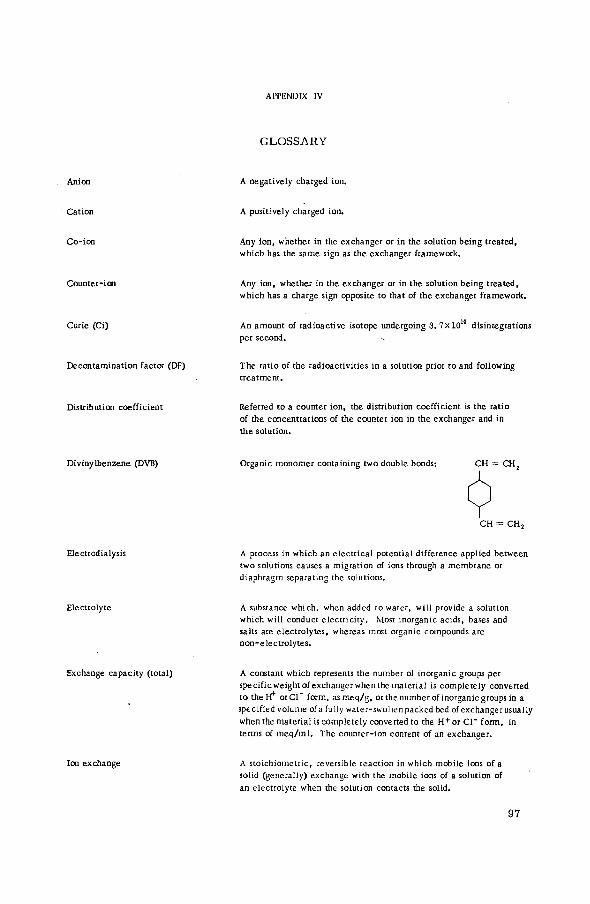
APPENDIX IV
GLOSSARY
Anion
Cation
A negatively charged ion.
A positively charged ion.
Co-ion Any ion, whether in the exchanger or in the solution being treated, which has the same sign as the exchanger framework.
Counter-i от Any ion, whether in the exchanger or in the solution being treated, which has a charge sign opposite to that of the exchanger framework.
Curie (Ci) An amount of radioactive isotope undergoing 3. 7 x 1 0 disintegrations per second.
Decontamination factor (DF) The ratio of the radioactivities in a solution prior to and following treatment.
Distribution coefficient Referred to a counter ion, the distribution coefficient is the ratio of the concentrations of the counter ion in the exchanger and in the solution.
Divinylbenzene (DVB) Organic monomer containing two double bonds: CH = CH,
CH = CH,
Electcodialysis A process in which an electrical potential difference applied between two solutions causes a migration of ions through a membrane or diaphragm separating the solutions.
Electrolyte A substance which, when added to water, will provide a solution which will conduct electricity. Most inorganic acids, bases and salts are electrolytes, whereas most organic compounds are non-electrolytes.
Exchange capacity (total) A constant which represents the number of inorganic groups per specific weight of exchanger when the material is completely converted to the H+ orCl" form, asmeq/g, or the number of inorganic groups in a specified volume ofa fully water-swollenpacked bed of exchangerusually when the materialis completely converted to the H + o r C l " f o r m , in terms of meq/ml. The counter-ion content of an exchanger.
Ion exchange A stoichiometric, reversible reaction in which mobile ions of a solid (generally) exchange with the mobile ions of a solution of an electrolyte when the solution contacts the solid.
97
Macroreticular resins Highly porous resins. (From 'macro' meaning 'large* and 'reticular* meaning 'netlike* or 'sievelike*).
Molecular sieves Materials with rigid, uniform pore structure which can sorb small molecules but completely exclude molecules larger than the structure pore openings.
MPC The maximum permissible concentration. This refers to maximum levels of radioactivity in water or in air as established by national or international commissions.
Nuclide
Permselectivity
A species of atom characterized by its nucleus.
From permeable-selective. Refers to that property of a membrane which permits certain species of ions to pass through the membrane while excluding other species.
Radioactivity The spontaneous disintegration of an unstable nuclide with emission of a particle or photon to form a different nuclide.
Regeneration With reference to ion-exchange materials, regeneration is defined as the process of removing those counter ions from the exchanger which had been absorbed during treatment of a solution and re-placing them with an appropriate ionic form for subsequent treat-ment of additional solution.
Roentgen An exposure dose of X- or gamma radiation such that associated corpuscular emission per 0 .001293 g of air produces in air ions carrying one electrostatic unit (esu) of quantity of electricity of either sign.
Selectivity (ion exchange) The preference of an exchanger for one species of counter ion over another.
A general term which includes absorption, an engulfing, and adsorption, an interface or surface attraction.
Volume reduction factor. The ratio of the volumes of radioactive waste prior to and following treatment. In concentration processes, the VRF > 1 ; in dilution systems, the VRF <1.
9 8
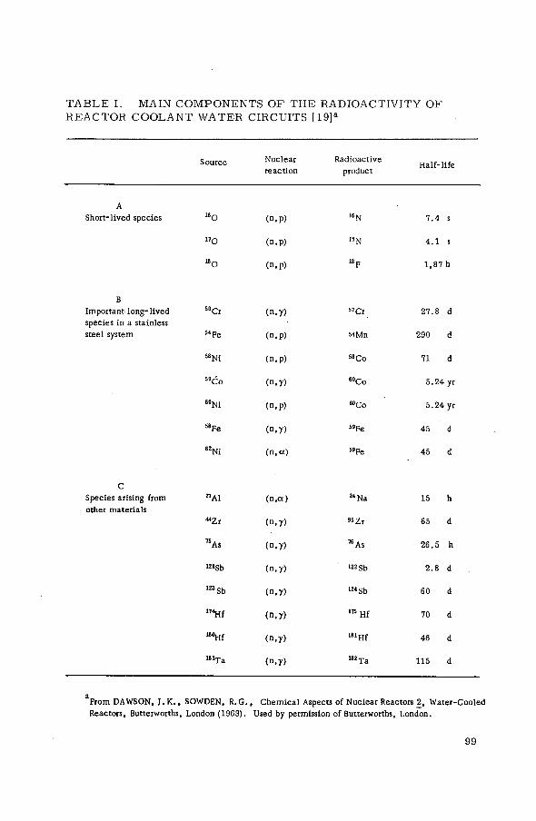
T A B L E I. MAIN COMPONENTS O F T H E RADIOACTIVITY O F R E A C T O R COOLANT W A T E R CIRCUITS [19] a
Source Nuclear reaction
Radioactive product
Half-life
A Short-lived species 16 О ( n . p ) 16 N 7 . 4 s
" О (n.p) 17 N 4 . 1 s
I B 0 ( n . p ) " F 1 , 8 7 h
В Important long-lived species in a stainless steel system
5°Cr
5 4 Fe
( n . y )
( n . p )
" C r
54мп
2 7 . 8 d
290 d
s 8 n í ( n . p ) 5 8 Co 71 d
5 9 Co ( n . y ) 6 0Co 5 . 2 4 yr
60Ni ( n . p ) «Со 5 . 2 4 yr
58 Fe ( n . y ) 59Fe 45 d
" N i (n.ot) 59Fe 45 d
С Species arising from other materials
" A l
« Z r
(n.Ot)
( n , y )
24 Na
« Zr
15 h
65 d
" A s ( n . y ) 76 As 2 6 . 5 h
I21Sb (n ,y ) 122 Sb 2 . 8 d
1 2 3 Sb ( n . y ) 124 Sb 60 d
1 T 4 Hf ( n , y ) ITS H f 70 d
1 8 °Hf ( n . y ) 181Hf 46 d
181T a ( n . y )
182 T a 115 d
aFrom DAWSON, J . K . , SOWDEN, R . G . , Chemical Aspects of Nuclear Reactors 2, Water-Cooled Reactors, Butterworths, London (1963). Used by permission of Butterworths, London.
9 9

S T A B L E II . E A R L Y R E A C T O R S U T I L I Z I N G I O N - E X C H A N G E D E M I N E R A L I Z A T I O N [20] о
Designation Location Moderator Reactor crit ical
Nominal power
Ion exchange {°h treated )
NRX
EL-1 (ZOE)
LITR
BSR-1
sura
JEEP
MTR
EL-2
SP
CP-5
WWR-C
R - l
BORAX-3
Chalk River, Ont . , Canada
Châtillon, Fontenay--aux-Roses, France
Oak Ridge, Tenn . , USA
Oak Ridge, Tenn . , USA
Los Alamos, N . M . , USA
Kjeller, Norway
Idaho Falls, Idaho, USA
Saclay, France
Aiken, S . C . , USA
Argonne, 111., USA
Moscow, USSR
Stockholm, Sweden
Idaho Falls, Idaho, USA
Heavy water
Heavy water
Light water
Light water
Light water in He solution
Heavy water
Light water
Heavy water
Light water
Heavy water
Light water
Heavy water
Light water
Jul. 1947
Dec . 1948
Feb. 1950
Dec. 1950
(as HYPO, 1944) Mar. 1951
Jun. 1951
Mar. 1952
Oct . 1952
Jul. 1953
Feb. 1954
1954
Jul. 1954
Jun. 1955
50 MW
150 kW
3 MW
1 MW
25 kW
450 kW
40 MW
2 MW
10 kW
5 MW
2 MW
600 kW
12 MW
20
2.1
3 1 /3
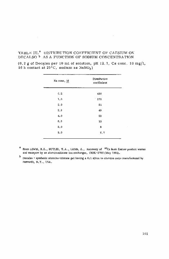
TABLE III.a DISTRIBUTION COEFFICIENT OF CAESIUM ON DECALSO b ASA FUNCTION OF SODIUM CONCENTRATION
(0. 2 g of Decalso per 10 ml of solution, pH 12. 7, Cs conc. 10 mg/1, 16 h contact at 25°C, sodium as NaNOs)
Na conc, M Distribution
Na conc, M coefficient coefficient
0 . 2 430
1 . 0 170
2 . 0 85
2 . 8 49
4 . 0 22
6 . 0 13
8 . 0 8
9 . 0 6 . 7
a From LEWIS, R . E . , BUTLER, T . A . , LAMB, E . , Recovery of 137Cs from fission-product wastes and transport by an aluminosilicate ion exchanger, ORNL-3765 (May 1965) .
k Decalso = synthetic alumino-silicate gel having a 6 : 1 silica to alumina ratio manufactured by Permutit, N . Y . , USA.
101

T A B L E IV. A P P R O X I M A T E ION-EXCHANGE S E L E C T I V I T Y C O E F F I C I E N T S [43] a
Ion Ex
Ion El
к * Ex
(50% sat'd) Ion-exchange material
Ion Ex
Ion El
к * Ex
(50% sat'd)
Cation Sulphonated styrene- h Li 0 . 8 divinylbenzene (DVB) (8%)
h Na 2 . 0
h к 3
h n h 4 3
h Ag 18
h Tl. 24
Na к 1 . 8
h Ca 42
Ni Ca 2 . 5
Sulph. styrene-DVB (5%) h Na 1 . 4
Sulph. styrene-DVB (25%) h Na 2 . 5
Chabazite Na к 1 4 . 4
Sodalite Na к 0 .06
Anion Quaternary ammonium Cl F 0 . 1 (strongly basic, styrene-DVB)
Cl Br 2 . 5
Cl I 18
Cl N0 3 3
Cl ОН 0 . 5
C104 SCN 0 . 6
a From KUNIN, R . , Elements of Ion Exchange. Reinhold Publishing Corporation, New York, 1960. Used by permission of Reinhold Publishing Corporation, New York.
1 0 2

T A B L E V . R E L A T I V E A F F I N I T I E S OF IONS F O R A STRONG-ACID R E S I N WITH VARYING P E R C E N T A G E S O F CROSSLINKING [44] a
Monovalent cat ions X - 4 b X - 8 X - 1 2 X - 1 6
H 1 . 0 1 . 0 1 . 0 1 . 0
Li 0 . 9 0 0 . 8 5 0 . 8 1 0 . 7 4
Na 1 . 3 1 . 5 1 . 7 1 . 9
Rb 1 . 9 2 . 6 3 . 1 3 . 4
Cs 2 . 0 2 . 7 3 . 2 3 . 4 5
Ag 6 . 0 7 . 6 12 17
Divalent cat ions
Mn 2 . 2 2 . 3 5 3 . 5 2 . 7
Zn 2 . 6 2 . 7 2 . 8 3 . 0
Co 2 . 6 5 2 . 8 2 . 9 3 . 0 5
Cd 2 . 8 2 . 9 5 3 . 3 3 . 9 5
• Ni 2 . 8 5 3 . 0 3 . 1 3 . 2 5
C a 3 . 4 3 . 9 4 . 6 5 . 8
Sr 3 . 8 5 4 . 9 5 6 . 2 5 8 . 1
Hg 5 . 1 7 . 2 9 . 7 14
Pb 5 . 4 7 . 5 1 0 . 1 1 4 . 5
Ba 6 . 1 5 8 . 7 1 1 . 6 1 6 . 5
a Reproduced by permission of Duoli te Resins, Diamond Alkal i Company, Western Divis ion, Redwood C i t y , C a l i f .
b X - no. = degree o f crosslinking in °¡o DVB, as X-4 - DVB.
1 0 3

T A B L E VI . a COMPARISON O F O B S E R V E D S E L E C T I V I T Y C O E F F I C I E N T S WITH V A L U E S C A L C U L A T E D B Y M Y E R S & BOYD [46]
Ion exchange Ь
Degree of crosslinking
№ DVB)
Ionic composition
{<% Na +)
Selectivity coefficient
calculated observed
N a + / L i + 2 0 1 . 2 5 1 . 1 2 i 0 . 0 3
50 1 . 2 4 1 . 1 0 ± 0 . 0 3
100 1 . 2 1 1 . 0 8 i 0 . 0 2
0 2 . 0 0 1 .72 à 0 . 0 3
N a + / L i + 8 50 1 .88 1 . 8 0 ± 0 . 0 4
100 1 . 7 2 1 . 8 9 ± 0 . 0 4
0 3 . 3 4 3 . 2 5 ± 0 . 0 7
24 50 2 . 9 2 2 . 4 0 ± 0 . 0 5
100 2 . 8 0 1 . 8 0 ± 0 . 0 4
0 0 . 9 9 1 . 0 2 i 0 . 02
2 50 1 . 0 8 1 . 0 7 ± 0 . 0 2
100 1 . 2 5 1 . 1 2 ± 0 . 0 3
0 1 . 3 5 1 . 3 8 i 0 . 0 3
N a + / H + ' 8 50 1 .66 1 . 5 2 i 0 . 0 3
100 2 . 2 4 1 . 2 0 ± 0 . 0 3
0 9 .36 6 . 3 8 t 0 . 1 3
24 50 3 . 7 9 2 . 3 2 ± 0 . 0 5
100 3 . 0 6 0 . 6 9 ± 0 .02
aReprinted from Journal of Physical Chemistry 60 (1956) 521, by permission of American Chemical Society, Easton, P a . , USA.
''ion exchangers: sulphonated polystyrenes of various degrees of crosslinking.
1 0 4

T A B L E VII . D E P E N D E N C E O F ION-EXCHANGE R A T E ON E X -P E R I M E N T A L C O N T R O L [ 5 0 ] a
Solid diffusion control
F i lm diffusion control
Counter- ion mobi l i ty
In solid phase
In aqueous phase
C o - i o n mobi l i ty
Part ic le size
Capac i ty o f ion exchanger
Nature o f f ixed ionic groups
Degree of crosslinking
Se lec t iv i ty o f ion exchanger
Concentrat ion of solution
Solution volume
Temperature
Rate of agi tat ion or flow
oc D No e f f e c t
No e f f e c t D
No e f f e c t No e f f e c t
cc 1 / r 2 oc 1 / r о о
No e f f e c t cc 1 / x
Slow when fixed No e f f e c t ionic groups associate with mobi le ions
Decreases with No e f f e c t increasing crosslinking
Preferred counter ion is taken up at a higher rate and released at a lower ra te , e x c e p t under cer ta in special (boundary) conditions
No e f f e c t ocC
Decreases with increasing solution volume
Increases with temperature , approx. 4 - 8 % / d e g С
N o effect
Increases with temperature , approx. 3-37o/deg С
Increases with agi ta t ion rate
D = interdiffusion c o e f f i c i e n t in the ion e x c h a n g e r .
D = interdiffusion c o e f f i c i e n t in the f i l m .
r 0 = bead radius.
x = concentrat ion o f f ixed ionic groups.
a F r o m HELFFERICH, F . , Ion Exchange , M c G r a w - H i l l . I n c . , New York ( 1 9 6 2 ) . Used by permission of M c G r a w - H i l l Book C o .
1 0 5

T A B L E VII I . R E L A T I V E ION-EXCHANGE R A T E S [49] a
Time Resin (50% equilibrium attainment)
(hydrogen form of resin)
Sulphonated polystyrene- DVB (8%)
Na+ 1 . 5 min ++
Ba 3 . 0 min +++
Al 5 . 5 min , ++++ Th 6 0 . 0 min
Organic dyes Days-months
Sulphonated polystyrene- DVB (20%)
+ Na 5 min
a From KUNIN, R . , Elements of Ion Exchange, Reinhold Publishing Corporation, New York, 1960. Used by permission of Reinhold Publishing Corporation, New York.
1 0 6
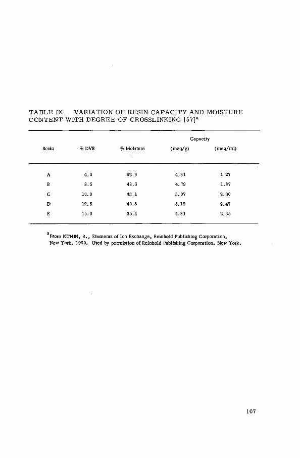
T A B L E I X . VARIATION O F R E S I N C A P A C I T Y AND M O I S T U R E C O N T E N T WITH D E G R E E O F CROSSLINKING [57] a
Capacity
Resin "¡o DVB % Moisture (meq/g) (meq/ml)
A 4 . 0 6 2 . 6 4 . 8 1 1 .27
В 8 . 5 4 8 . 6 4 . 7 9 1 . 8 7
С 1 0 . 0 4 3 . 1 5 . 0 7 2 . 3 0
D 1 2 . 5 4 0 . 8 5 . 1 2 2 . 4 7
E 1 5 . 0 3 5 . 4 4 . 8 1 2 . 6 5
a From KUNIN, R . , Elements of Ion Exchange, Reinhold Publishing Corporation, New York, 1960. Used by permission of Reinhold Publishing Corporation, New York.

о TABLE X. SYNTHETIC CATION EXCHANGERS oo
a. Polystyrene base, bead form addition polymers
Exchange capacity Physical characteristics Operational controls
Trade name Manufacturer a Functional
Ion form (meq/g) (meq/ml) Moisture Size Max.oper. pH Remarks group
(dry) (wet) (wt .») (mm) temp. ("С) range
Allasion CS Prosim, France - s o ; ь 0 . 3 - 0 . 6 110 1 - 1 4
Amberlite IRN- 77 Rohm & Haas C o . , - s o ; H 4 . 7 55 0 . 3 - 1 . 2 Nuclear grade XE-100 USA -SOj" Na 4 . 5 1 . 5 5 6 - 6 0 120 0 - 1 4 ~57° DVB
IRN-163 distributed by - s o ; Li 4 . 6 55 0 . 3 - 1 . 2 150 Nuclear grade IRN-169 MalUnckrodt, USA - s o ; NH< 4 . 4 55 0 . 3 - 1 . 2 150 Nuclear grade IRN-218 and - s o ; Li 4 . 6 55 0 . 3 - 1 . 2 150 Nuclear grade
IR-120 Tokyo Organic - s o ; Na 4 . 3 - 5 1 . 9 4 4 - 4 8 0 . 3 - 1 . 2 120 0 - 1 4 ~ 8% DVB IR-122 Chemical Industry - s o ; Na 4 . 3 - 5 2 . 1 3 9 - 4 3 0 . 3 - 1 . 2 120 0 - 1 4 ~ 107° DVB IR-124 Ltd., Japan - s o ; Na 4 . 3 - 5 2 . 2 3 7 - 4 1 0 . 3 - 1 . 2 120 0 - 1 4 ~ 12% DVB
200 - s o ; Na 4 . 3 1 .75 4 6 - 5 1 0 . 3 - 1 . 2 120 0 - 14 'Macroreticular' resins 200C - s o ; Na 4 . 3 1 .75 4 6 - 5 1 120 0 - 1 4 'Macroreticular' resins
Amberlyst 15 - s o ; 4 . 9 1 . 2 6 0 - 6 6 120 0 - 1 4 'Macroreticular' resins (Amberlyst resins are designed for non-aqueous applications)
Diaion SK 1A Mitsubishi Chemical - s o ; Na - 1 . 9 4 3 - 5 0 0 . 3 - 1 . 2 120 0 - 1 4 ~ 87° DVB SK IB Industries Ltd., - s o ; Na - 1 . 9 4 3 - 5 0 0 . 3 - 1 . 2 120 0 - 1 4 ~ 8% DVB SK-102 Japan -SOi Na - 0 . 6 7 2 - 82 0 . 3 - 1 . 2 120 0 - 1 4 ~ 27» DVB SK-103 -SOi Na - 0 . 9 6 4 - 7 4 0 . 3 - 1 . 2 120 0 - 1 4 ~ 3% DVB SK-104 - s o ; Na - 1.2 5 7 - 6 7 0 . 3 - 1 . 2 120 0 - 14 ~ 47" DVB SK-106 - s o ; Na - 1 . 6 4 7 - 5 7 0 . 3 - 1 . 2 120 0 - 14 ~ 6% DVB SK-110 - s o ; Na - 2 . 0 3 5 - 4 5 0 . 3 - 1 . 2 120 0 - 14 ~ 107> DVB SK-112 - s o s Na - 2 . 1 3 2 - 4 2 0 . 3 - 1 . 2 120 0 - 1 4 ~ 121o DVB SK-116 - s o ; Na 2 . 1 2 7 - 3 7 0 . 3 - 1 . 2 120 0 - 1 4 ~ 167° DVB
Dowex 50-X8 Dow Chemical C o . , - s o ; H 5 . 0 1 .7 53 0 . 3 - 0 . 8 150 ~ 87° DVB 50W -X4 USA - s o ; H 5 . 0 1 .7 53 0 . 3 - 0 . 8 150 ~ 47° DVB; replace Dowex
marketed by 50 resins 50W-X8 Nalco Chemical C o . , - s o ; Na 4 . 8 1 . 9 4 2 - 4 8 0 . 3 - 0 . 8 150 ~ 87) DVB 50W-X10 USA -so; H - 1 . 9 4 6 - 5 2 0 . 3 - 0 . 8 150 ~ 10% DVB 50W-X12 - s o ; H - 2 . 1 4 2 - 4 8 0 . 3 - 0 . 8 150 ~ 127° DVB 50W-X16 - s o ; H - 2 . 3 3 6 - 4 2 0 . 3 - 0 . 8 150 ~ 167° DVB MPC-1 - s o ; H 4 . 5 - 4 . 9 1 . 6 - 1 . 8 0 . 4 - 1 . 2 300 Macro porous

Duolire C-20 Diamond Alkali - s o ; Na 5 . 1 2 . 2 45 -•51 0 . 3 - 1.2 ISO ~ 8% DVB C-25 -so', Na 5 . 1 1 . 7 55 - 62 0 . 3 - 1 . 2 120 Porous resin ~ DVB
ES-63 -Po; H 6 . 6 3 . 3 0 . 3 - 1 . 2 100 4 - 14 Intermediate acid
Imac C-12 IMACTI, Netherlands - s o ; Na 2 . 0 0 . 3 - 1 . 2 120 0 - 14 " C-16P - s o ; Na - 2 . 1 0 . 3 - 1 . 2 120 0 - 14
Ionac C-240 Permutit Q, marketed by Ionac C o . , USA
Kastel C-300 Montecatini, Italy - s o ; Na 4 . 2 5 - 45 0 . 3 - 1 . 2 120 0 - 14 ~ 87» DVB " C-300 AGR - s o ; Na 4 . 5 - 4 . 7 - 45 0 . 3 - 1 . 2 120 0 - 14 ~ 12% DVB " C-300 P - s o ; Na - 1 . 7 53 0 . 3 - 1 . 2 120 0 - 14 Highly porous
KF-1 NIIP, USSR - p o p - 5 . 0 - - Intermediate acid
KF-2 -CH,PO|" 7 . 0 - - Intermediate acid & -POf-
KU-2-8 - s o ; Na, H 4 . 7 - 60 0 . 3 - 1 . 5 120 ~ 87» DVB; 2 , 8 , 1 2 , 167» also available
KU-2-8-CHS .. - s o ; H 4 . 7 4 5 - 65 0 . 4 - 1 . 5 - Special purity
Lewatit S-100 Farbenfabriken - s o ; - 4 . 7 5 2 . 5 4 0 - 45 0 . 5 - 1 . 0 120 0 - 14 ~8ToDVB S-115 Bayer A . G . , - s o ; 4 . 6 2 . 4 4 0 - 45 0 . 3 - 2 . 0 120 0 - 14 Higher resistance to oxidizing
Fed. Rep. of Germany agents " SP-100 - s o ; - 4 . 7 5 1 . 3 0 . 3 - 1 . 4 120 0 - 14 Macroporous
Mykion PS MUKY, Hungary - s o ; 4 . 0 1 .57 - - -
PSM - s o ; 4 . 0 1 .0 -
Nalcite HCR Dowex 50-X8 marketed by Nalco Chemical C o . , USA HGR " 50-X10 .. „
HDR " 50-X12
Permutit Q Permutir Co. , - s o ; Na, H 4 . 6 1 . 9 4 5 - 55 0 . 3 - 1 . 2 120 0 - 13 - 107o DVB ~ QB USA - s o ; Na, H 5 . 0 - 4 . 6 2 . 1 - 1 . 9 4 5 - 55 0 . 3 - 1 . 2 120 0 - 13 ~ 12% DVB " QC - s o ; Na 5 . 0 2 . 1 4 5 - 55 0 . 3 - 1 . 2 120 0 - 13 ~ 157» DVB
QR - s o ; Na 3 . 9 1.7 4 5 - 55 0 . 3 - 1 . 2 120 1 - 14 High stability to oxidizing conditions
NQ (H, NH,, Li) - s o ; H, NHj. Li 4 . 6 1 . 8 4 5 - 55 0 . 3 - 1 . 2 120 0 - 13 Nuclear grade NQ 'Li - s o ; ' L i 4 . 6 1 . 8 4 5 - 55 0 . 3 - 1 . 2 150 - Nuclear grade
а See Appendix I for full паше of manufacturers. О ^ - S O j group resins are strong-acid resins. CO

T A B L E X. (cont.)
Trade паше Manufacturer a Functional
group Ion form
Exchange capacity
(meq/g) (meq/ml) (dry) (wet)
Physical characteristics
Moisture Size (wc.%) (mm)
Operational controls
Max. oper. pH temp. ( 'C) range
Remarks
Permutit RS Permutit A. G . , Fed. Rep. of Germany
-so; b Na 5 . 2 2 . 2 - 0 . 3 - 1 . 2 150 - Nuclear grade
Resex P Jos. Crosfield, UK -so; Na 4 . 8 2 . 0 - 0 . 3 - 1 . 2 120 -
S-katex VyzkumnJ iistav synthetick^ch pryskyfic a 1акб, Pardubice, CSSR
-so; H 4 . 9 0 . 5 0 . 3 - 1 . 2 120 0 - 14
SDV Moskovsk Chem. Technol. Inst. , USSR
-so; - 4 . 2 - - 0 . 3 - 1 . 4 - - Fine ground
Wolfatit KPS R(H, L, K, N)
VEB Farbenfabrik Wolfen, German Democratic Rep.
-so; -so;
Na H, Li, К and NH4
4 . 5 1 . 8 1 . 8
4 5 - 5 3 0 . 3 - 1 . 2 0 . 3 - 1 . 2
115 115
3 - 1 4 3 - 1 4 Nuclear grade
Zerolit 225 Zerolit Ltd., UK -so ; Na 4 . 8 2 . 1 4 5 - 5 0 0 . 3 - 1 . 2 120 0 - 14 Standard resin 8% DVB* also available with 1, 2 , 4 .5 , 12 & 20?o DVB
b. Vinyl addition polymers (acrylic, methacrylic)
Trade name Type of
acid Manufacturera Functional
group Ion
form
Exchange capacity
(meq/g) (meq/ml) (dry) (wet)
Physical characteristics
Moisture Size (wt.%) (mm)
Operational controls
Max. oper. pH temp.( 'C) range
Remarks
Amber lite IRC-50 IRC-84
Weak Rohm & Haas C o . , USA
-coo" -COO"
H H
1 0 . 0 - 1 0 . 2 10 .0
3 . 5 3 . 5
4 3 - 5 3 4 3 - 5 0
0 . 3 - 1 . 2 0 . 3 - 1 . 2
120 150
5 - 1 4 4 - 1 4
Capacities - in alkaline médiat spherical beads
CFB-P Strong Chem. Fabrik Budenheim, Fed. Rep. of Germany
-oso; - - 100
Duolite CS-101 Weak Diamond Alkali C o . , USA
-COO" H 10 .0 3 . 5 0 . 3 - 1 .2 100 ~ l0<7o DVB; beads

Ionac С - 2 7 0
Imac Z5
Kastel C-100
Karboxylovy
KB-1 KB-2 KB-3 KB-4P-2
Kn
KF-3
KF-4
KU-3
Mykion KMK - CP
Petmutit С
H-70
Wolfatit CP
Permutit H-70 marketed by Ionac Co. ,
Weak
Weak
Weak
Weak
Weak
Intermed.
Intermed.
Strong
Weak
Weak
1МАСП, Netherlands
Montecatini, Italy
Spolek pro chemlckou vyrobu, CSSR
NIIP, USSR
Moskovsk Chem. Technol. Inst . , USSR
NIIP, USSR
MUKY, Hungary
Permutit A . G . , Fed. Rep. of Germany Permurit C o . , USA
VEB Farbenfabrik Wolfen, German Democratic Republic
USA
-COO"
-COO"
-COO"
-COO" -coo" -COO" -coo"
-COO"
-PO,
CH¡POÍ"
-soi
-coo"
-COO" •
-coo"
-COO"
-coo"
H
H
Na
Zerolit Ltd., UK
a See Appendix I for full name of manufacturers. Ь -SOs group resins are strong-acid resins.
3 . 0 - 0 . 3 - 1 . 2
3 . 0 4 5 - 5 0 0 . 3 - 1 .2
10 .0 3 . 5 - 0 . 3 - 1 . 2
10 .0 - - 0 . 3 - 1 . 5 1 0 - 1 1 - - 0 . 3 - 1 . 0
6 - 7 - - 0 . 3 - 1 . 5 9 . 5 - 0 . 2 5 - 1 . 0
6 . 0 - - 0 . 2 5 - 1 . 5
3 . 5
5. 5
5 . 5 - - -
8.6 1.2 8.0 2.8
1 0 . 0 4 . 0
6 . 5 2 . 4 4 0 - 50 0 . 3 - 1 . 2
1 0 . 0 3 . 5 4 3 - 5 3 0 . 5 - 2 . 0
1 0 . 0 3 . 5 - 0 . 3 - 1 . 2
100 4 - 14 Beads
110 0 - 1 4 Beads; ~ 10% DVB
120 5 - 14 Beads
Beads Beads Beads; acrylonitrlle- DVB Beads
Fine ground
Fine ground
100 6 - 1 4 Beads
120 5 - 14 Beads
100 7 ~ ffb DVB, beads
100 - Beads; 2 .5 & 4.5% DVB available

T A B L E X . ( cont . )
с . Pheno l i c r e s i n s
Trade паше Type of
acid Manufacturer
Functional group
Ion form
Exchange capacity
(meq/g) (meq/ m 1) (dry) (wet)
Physical characteristics
Moisture Size (wt.Vo) (mm)
Operational controls
Max.oper. pH t e m p . f C ) range
Remarks
Dorolit FK-22 Strong MUKT. Hungary -SO3, OH" - 2 . 7 0 . 6 - - Fine ground
Dowex CCR-1 Weak Dow Chemical C o . , -COO" H - 1 . 4 0 . 3 - 0 . 8 100 Marketed by Nalco Chem. USA -OH C o . , USA, granular
Duolite C - 3 Strong Diamond Alkali -so ; H 2 . 9 1 .2 0 . 3 - 2 . 0 60 0 - 9 Beads; -CHzSO¿ groups C o . , USA
" C - 1 0 -so; H 2 . 9 0 . 6 0 . 3 - 2 . 0 40 0 - 9 Beads; -CH2SO3 groups
Lewatit KSN Strong Farbenfabriken -so ; - 4 . 0 1 . 6 4 5 - 5 0 0 . 3 - 1 . 5 30 0 - 8 Granular Bayer A. G . . Fed. Rep. of Germany
CNS Strong П -SOS. - 5 . 0 2 . 5 3 6 - 4 3 0 . 3 - 1 . 6 40 0 - 10 Granular & weak - coo" H
CNO Weak " -coo" - 4 . 0 2 . 4 3 0 - 35 0 . 3 - 1 .6 40 0 - 10 Granular
MSF-3 Weak Moskovsk Chem, - s o ; . - 4 . 3 - 0 . 3 - 2 . 0 - Fine ground Tech. Inst . , USSR -OH
Mykion FG Strong MUKY, Hungary -CH¡SO¡ , -OH - 2 . 8 0 . 9 - -
P « » -OH - 2 . 2 0 . 6 5 - -
NSF Strong Moskovsk Chem. -so ; - 3 . 0 - 0 . 3 - 1 . 5 - Fine ground Tech. Inst., USSR
Permutit H Weak Permutit C o . , USA -coo" 5.0 1 . 9 - 65 Granular Permutit A . G . , -coo" 4 . 0 - - 40 Granular Fed. Rep. oí Germany
Resex W Weak Jos. Crosfield, UK -coo" - 2 . 5 - 3 . 0 - - - Granular
RF Intermed. Moskovsk Chem. -PO|" 4 . 3 - - -
Tech. Inst. , USSR

Strong Institut vysokomol. USSR
-so;. •OH
SNF
FN-katex
KB-5
KU-I
KU-1G
KRFU
Strong
Strong
Weak
Strong
Strong
Weak
Chemicky kombinat záluZT, CSSR
Institut vysokomol., USSR
-so;, -OH
-so;
-ch2coo",oh
-so;, -он
-SOj", -OH
-coo"
KU-5 KU-6
KU-6F KU-7 KU-8 KU-9 KU-21
Staionit F-extra
P C\' CV
Strong Strong
& weak
Strong
Strong
Strong
NIIP, USSR
Chemicky kombinát záluZT, CSSR
veb Farbenfabrik Wolfen, German Democratic Republic
-so; -SQ>", -coo" -coo" -COO" -sc5 ,-coo" -s05.-0h -so;
-ch2so; -он
•so,"
-so; -coo" -coo"
Na Na
Zerolit 215 " 216
Strong Weak
Zerolit Ltd., UK -SO,, OH -COO", OH
Na h
5 . 2 - - 0 . 3 - 1 . 5
5 . 2 - - 0 . 3 - 1 . 5
0 . 5 4 - 0 . 3 - 1 . 5
7 . 5 - - 0 . 2 5 - 1 . 5
4 . 0 - 50 0 . 3 - 3 . 0
4 . 5 - 50 0 . 3 - 2 . 0
4 . 0 - - 0 . 2 5 - 1 . 5
5 . 0 - - 0 . 3 - 2 . 0 5 . 5
5. 6 5. 5 6. 0
6 . 0 . . . 5 . 5
0 .2 - 0 . 5 - 2 . 5
2 . 9 - - 0 . 3 - 1 . 5
1 . 9 - - 0 . 3 - 1 . 5 2 . 0 - - 0 . 3 - 1 . 5 4 . 0 l .C 4 0 - 5 0 0 . 3 - 1 . 5
0 .92 - 0 . 3 - 1 . 2 2 . 5 1 . 1 - 0 . 3 - 1 . 2
Fine ground
Fine ground
1 - 9 . 5 Beads, fine ground
Dark brown grains
Beads, black or brown
Fine ground
Beads, fine ground
Fine ground Fine ground
1 - 9 . 5 Fine ground
50 - Granular
50 - Granular 30 - Granular 40 0 - 8 Granular
40 0 - 9 Granular 30 0 - 9 Granular

£ T A B L E X . (cont.)
d . Inorganic e x c h a n g e r s (synthetic zeolites)
Matrix Chemical or trade name
Manufacturer Functional
group
Exchange capacity
(meq/g) (meq/ml) (dry) (wet)
Operational controls
Max. oper. pH t e m p . ( ' C ) range
Physical form Remarks
Alum inosilicates Decalso Permutit C o . , USA AlOjNa 1 . 4 0 . 5 3 40 6 . 9 - 8 . 0 Granules Na form; intermediate capacity
Doucil Jos. Crosfield, UK - 1 .2 - - Granules
Molecular Davison Chemical Div., - - 590 - Powder, pellets, sieve ЗА W.R. Grace Co. , USA granules
Molecular - - 590 - Powder, pellets, sieve 4A granules
Molecular - - 590 - Powder, pellets, sieve 5 A granules
Molecular Powder, pellets sieve 10 A
H - - 590 - granules
Molecular Linde C o . , USA - 5 . 3 400 - Pellets Synthetic zeolites; nominal sieve 4A pore diameter 4 Д
Molecular - - 400 - Pellets Synthetic zeolites; nominal sieve 5A pore diameter 5 Â
Molecular - 4 . 8 400 - Pellets Synthetic zeolites; nominal sieve 13X pore diameter 10 A
AW300 - 1 .7 - - Nominal pore diameter 4 A AW400 - 2 . 0 - -
AW500 2 . 0 - - Nominal pore diameter 5 A
Zeolon Norton, USA - 1 . 9 538 Pellets or . Synthetic mordenite (Na form) powder
Ammonium-molybdoarsenate Kd (Cs) = 400 to 4000 (method of prep. )
Ammonium-12-molybdophosphate Bio-Rad AMP-1 Bio-Rad Labs, USA 0 . 7 (Cs) K d (Cs) = 6000
Ammonium-tungstophosphate K(] (Cs) = 3300 to 3500 (method of prep.)

Matrix Chemical or trade name Manufacturer Exchange capacity
(ftieq/g) (dry) Remarks
Arsenates Ferric arsenate Zirconium arsenate
At pH 3 . 5 5 - 1 0 . 9 5 : 1 . 1 8 - 5 . 7 3 (Sr) At pH 3 .12 - 10 .68 : 2 . 87 - 6 . 1 5 (Sr)
Cerium (IV) compounds Ceric phosphate, H*form; eerie phosphate, NH4 form; ceric oxide. AH not available commercially
At pH 0 . 1 0 - 1 1 . 7 : 0 . 0 7 - 3 . 2 4 Na+ ion-exchange capacity
Ferrocyanide-molybdate Not available commercially FEM
Hydrous oxides Not ávailable commercially CO (OH) s Sn(OH)4
Al (OH)s
Ni (OH)s Fe(OH)3
Lead sulphate (tribasic)
At pH 7 - 1 0 : 0 . 2 5 - 0 . 7 8 At pH 4 - 11: 0 . 7 3 - 1 . 7 8 At pH 7 - 1 0 : 0 . 1 0 - 1 . 2 4 At pH 6 . 5 - 10: 0 . 0 2 - 2 . 2 5 At pH 6 - 1 0 : 0 . 1 1 - 2 . 1 9 (Sr) At pH 1 - 6 . 7 : 8 . 5 - 0 . 8 (anion exch.) At pH 7 . 2 - 1 2 . 5 : 0 . 1 - 7 . 5 (cation exch.)
Blue particles White particles White particles Green particles
Phosphates ABEDEM Sn ABEDEM TiA ABEDEM TiB ABEDEM Zr
SERAI, Belgium 3 .70 (H) 7 . 5 0 (H) 9 . 5 0 (H) 5 . 2 0 (H)
Potassium hexacyanocobalt (II) ferrate (III) Not available commercially 6 . 0 (Cs)
Quinoline- moly bdophosphate Kd (Cs) = 1500 ml/q
Silicates А Ь О з - Х S i0 2
SN0 2 • X SiOj AnO • X S i0 2
(X = varying number of silicates)
Thorium-base Thorium phosphate At pH 3 . 0 - 1 1 . 0 : 0 . 3 0 - 1 . 1
Titanium-base Titanium phosphate At pH 2 . 5 - 3 . 1 . 5 : 0 . 2 0 - 3 . 5
Zirconium-base Zirconium arsenate Zirconium oxide Zirconium phosphate (ZP) Zirconium phosphate with citrate (Z CP) Zirconium tungstate Bio-Rad ZP-1
Z T - 1 ZM-1
Bio-Rad Labs, USA
At pH 2 . 5 - 1 , 3 0 : 0 . 3 0 - 3 . 0
At pH 3 , 5 - 1 1 . 5 : 0 . 1 0 - 5 . 5
At pH 2 . 5 - 1 2 . 0 : 0 . 3 - 1 . 5
1 . 0

T A B L E XI. N A T U R A L C A T I O N E X C H A N G E R S
a. O r g a n i c
Matrix Mineral or trade name
Manufacturer Functional group
Exchange capacity
(meq/g) (meq/ml) (dry) (wet)
Operational controls
Max. oper. pH temp. ( 'C ) range
Physical form Remarks
Coals Dusarit S M ACTI, Netherlands -S03 -COONa
0.7 (strong) 0.35 (weak)
80 0 - 14 Granules Polyfunctional
Imac С 19 " -so; -COOH
0.3 (strong) 1.0 (weak)
80 4 - 1 4 Granules Polyfunctional
Soucol los. Crosfield, UK -so; 1 .8 0 .6 30 Granules
Zeokarb-H Permutit C o . , USA -so; -COOH
1.6 0.56 70 0 - 8.5 Granules Intermediate acidity
Brown coal (lignite)
Local - Mol, Belgium Idaho, USA
-COOH 0.45 At pH 4 .1 : 0 . 0 2 - 1 . 0 8
Peat Local - Poland 0 . 0 5 - 0 . 4
b. Inorganic
Greensand (stabilized)
Zero lit Zerolit Ltd., UK
Greensand (stabilized)
Zeodur Permutit C o . , USA AlOjNa 0.11 0.14 60 6.2 - 8.0 Granules Na form
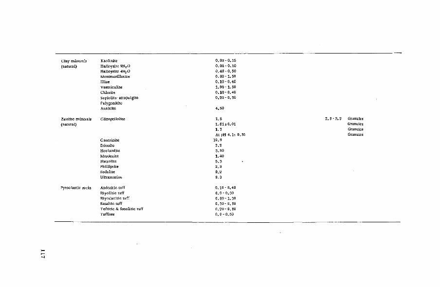
Clay minerals Kaolinite (natural) Halloysite 2НгО
Halloysite 4H2 О Montmorillonite
Zeolite minerals (natural)
Illite Vermiculite Chlorite Sepiolite- attapulgite Palygorskite Analcite
Clinoptilolite
Cancrinite Erionite Heulandite Mordenite Natrolite Phillipsite Sodalite Ultramarine
Pyroclastic rocks Andesitic tuff Rhyolitic tuff Rhyodacitic tuff Basaltic tuff Tefritic & fonolitic tuff Tuffites
0 . 0 3 - 0 . 1 5 0 . 0 5 - 0 . 1 0 0 . 4 0 - 0 . 5 0 0. 8 0 - 1 . 5 0 0 . 1 0 - 0 . 4 0 1 . 0 0 - 1 . 5 0 0 . 1 0 - 0 . 4 0 0 . 2 0 - 0 . 3 0
4.50
1 .5 2 .8 - 3 .2 Granules 1.61 ±0.01 Granules 1 .7 Granules At pH 4 .1 : 0.35 Granules
10.9 .2.2 3.30 1.40 5 .3 2 . 3 9 .2 8 .3
0.10 - 0.40 0 . 0 - 0 . 3 0 0 . 8 0 - 1 . 3 0 0 . 3 0 - 0.80 0 . 2 0 - 0 . 8 0 0 . 0 - 0 . 5 0

T A B L E XII. SYNTHETIC ANION EXCHANGERS
a. Strong base polystyrene addition polymers
Type I [functional group - N (CH 3) 3]
Exchange capacity Physical characteristics Operational controls
Trade name Manufacturer Ion form (meq/g) (meq/ml) Moisture Size Max.oper. pH Remarks (dry) (wet) (wt.%) (mm) temp. CC) range
Amberllte IRA-400 Rohm & Haas C o . , USA CI 3 . 7 1 . 4 42-• 88 0. . 3 - 0 . 0 8 60 (OH) 0 - 1 4 Beads, ca . 8% DVB: avail , in larger particle distributed by size as 400 С
IRA-401 Tokyo Organic Chemical CI 3 . 5 1 .0 53-•58 0. . 3 - 0. 8 60 (OH) 0 - 1 4 Beads, porous IRA-401S Industry Ltd., CI 3 . 4 0 . 8 59-•65 0. . 3 - 0. 8 60 (OH) 0 - 1 4 Beads, porous ЮА-402 Japan CI 4 . 4 1 .25 50-•57 0. , 3 - 1 .2 80 (CI) 0 - 14 Beads, porous
бо(он) IRA-900 CI 4 . 4 1 . 0 60-•64 0, . 3 - 1 .2 60 (OH) 0 - 1 4 Beads, porous, mean pore size 250 'A* IRA-904 CI 2 . 6 0 . 7 56-•62 0, , 3 - 1 . 2 60 (OH) 0 - 1 4 Beads, porous, mean pore size 645 'A' IRN-78 OH 3 . 5 - 60 0, . 3 - 1 . 2 60 (OH) - Reactor grade
AV-15 NIIP, USSR - 3 . 0 - - - Beads AV-17-6 CI 4 . 3 - 40-•60 0. 35 - 1 .2 50 - Beads; 6% DVB AV-17-8 CI 3 . 8 - 4 . 5 - 40 -•60 0. 3 5 - 1 . 2 50 - Beads; 8% DVB A V - 1 7 - 8 - 3 . 4 - 0. 4 - 1 . 2 - - Beads, special porosity
Diaion SA 10A Mitsubishi Chemical CI - 1 .2 43 -•47 0. 3 - 1 . 2 60 (OH) 0 - 12 Beads; 8% DVB " SA 101 Industries Ltd., CI - 0 .85 50- 65 0. . 3 - 1 . 2 60 (OH) 0 - 1 2 Beads, porous, low crosslinking " SA 11A Japan CI - 0 .85 55-•65 0. 3 - 1 . 2 60 (OH) 0 - 1 2 Beads, porous, 4°¡o DVB " SA 100 CI - 1 . 0 - 1 . 3 50-•60 0. 0 7 - 0 . 1 5 - 0 - 1 2 Beads, analytical uses
Dowex 1 Dow Chemical CI 3 . 5 1 .33 43 0. 3 - 0 . 8 50 0 - 1 4 Beads, ca . 8% DVB: 1, 2 , 4 t % DVB C o . , USA also available
" 21K CI 4 . 5 1 .25 57 0. 3 - 0 . 8 50 0 - 1 4 Beads; improved mech. stability " 11 CI 4 . 0 1 .24 57 0. 3 - 0 . 8 50 0 - 1 4 Beads: uranium recovery
Duolite A-101D Diamond Alkali CI 4 . 2 1 .4 50- 55 0. 3 - 1 . 2 60 (OH) 0 - 1 4 Beads " ES-111 C o . , USA CI 4 . 7 1 .0 45 -•50 0. 3 - 1 . 2 40 (OH) 0 - 1 4 Limited quantities; beads
Imac S 5 -40 1MACTI, Netherlands CI - 1 .0 55 0. 4 - 0 . 8 5 50 (OH) 0 - 1 4 Beads " S 5 - 50 CI - 1 . 2 0. 4 - 0 . 8 5 50 (OH) 0 - 1 4 Beads
Ionac A-540 (Permutit S - l , marketed by Ionac C o . , USA)

Kastel A-500 Montecatini, Italy CI 3 . 0 0 . 3 - 1 .0 60 (OH) 0 - 14 Beads A-500P CI 3 . 3 0 . 3 - 1 .0 60 (OH) 0 - 14 Beads, porous
Lewatit M-500 Farbenfabriken CI 4 . 0 1 . 6 0 . 3 - 1 .2 70 0 - 14 Beads " MP-500 Bayer A. G . , CI 4 . 0 1 .2 0 . 3 - 1 .6 70 0- 14 Beads, porous " M-600 Fed. Rep. of Germany 3 .7 1 .6 0 . 3 - 1 .2 40 0 - 14 Beads, porous
MP- 600 3 . 7 1 . 1 0 . 3 - 1 . 5 40 0 - 14 Beads, porous
Nalcite SBR (Dowex 1, marketed by Nalco Chemical Co . . USA) SBR-P Porous
Permutir ESB Permutit A. G. , CI 3 . 2 1 .2 70 Beads ESB-26 Fed. Rep. of Germany CI 3 . 3 1 . 3 - 70 Beads
Permutit s - 1 Permutit C o . , CI 3 . 6 1 . 0 50 - 60 0 . 3 - 1 .2 100 0 - 14 Beads NSI USA OH 3 . 5 1 .0 50-• 60 0 . 3 - 1 .2 60 0 - 14 Beads, nuclear grade
Resenex HBL Jos, Crosfield, 3 . 5 1 . 5 60 Beads
HBT UK - 3 . 5 - 60 Beads
3 -S -TM anex Vyzkumny ústav CI 3 .45 1 .35 0 . 3 - 0 . 8 40 (OH) 0 - 12 synthetickych pryskyrïc a lakb. Pardubice, CSSR
Wolfatit ES VEB Farbenfabrik CI 3 . 5 0 . 5 65-•75 0 . 5 - 2 . 0 60 (OH) 2 - 10
SBT Wolfen, CI 3 .0 0 . 9 53-• 63 0 . 6 - 2 . 0 - 0 - 14 Uranium recovery, beads SBW German Democratic Rep. CI 3 . 5 0 . 9 58-• 68 0 . 3 - 1 . 5 60 0 - 11 Beads RO OH 0 . 9 0 . 3 - 1 . 5 60 0 - 14 Beads, nuclear grade
Zerolit FF-1P Zerolit Ltd., CI 4 . 0 1 .2 0 . 3 - 1 .2 60 Beads, 7 - 9% DVB K-MP UK CI - - - Beads, macro porous
b. Strong base polystyrène addition polymers Type II [functional group - N(CH2OH) ( C H 3 ) J
Amberlite IRA-410 Rohm & Haas C o . , USA Cl IRA-910 distributed by Cl IRA-911 Tokyo Organic Chem. Cl
Ind, Ltd., Japan
3 . 3
2 . 7
1 .40 1.10
0 . 9
4 0 - 4 5 0 . 3 - 0 . 8 5 5 - 6 0 0 . 3 - 0 . 8 4 2 - 4 4 0. 3 - 1 .2
40 (OH) 40 (OH) 40 (OH)
0 - 1 4 Approx. 8% DVB, beads 0 - 1 4 Beads; macroreticular 0 - 1 4 Beads; macroreticular
Diaion SA 20A - SA 21A
Mitsubishi Chemical Ind. Ltd., Japan
Cl Cl
1 . 3 0.8
4 0 - 4 5 5 5 - 6 5
0 . 3 - 1 . 2 0 . 3 - 1 . 2
40 (OH) 40 (OH)
0 - 1 2 Bead s 0 - 1 2 Beads, porous

^ T A B L E XII. ( cont . ) to о
Exchange capacity Physical characteristics Operational controls
Tradename Manufacturer Ion form (meq/g) (meq/ml) Moisture Size Max.oper. pH Remarks (dry) (wet) (wt.%) (mm) temp. (°C) range
Dowex 2
Duolite A-102D
Imac S5-52
Ionac A-550
Kastel A-300
Nalcite SAR
Permutit ES ES-26
Permutit S - 2
Dow Chemical C o . , USA
Diamond Alkali C o . , USA
Cl
Cl
3 . 5
4 . 2
IMACTI, Netherlands Cl
(Permutit S - 2 . marketed by Ionac C o . , USA)
Montecatini, Italy Cl 3 . 2
(Dowex 2 , marketed by Nalco Chemical C o . , USA)
Zerolit N-1P " P-1P
Permutit A . G . , Fed. Rep. of Germany
Permutit C o . , USA
Vyzkumny ústav synthetickych pryskyric a lakfi, Pardubice, CSSR
VEB Farbenfabrik Wolfen, German Democratic Republic
Zerolit Ltd., UK
Cl Cl
Cl, OH, SO,
3 .2 3 . 3
3 . 5 (Cl) 3 . 5 (OH, SOj)
1 .33
1 . 4
1.2
1 .2 1 .3
Cl Cl
1.10 1.14
4 5 - 50 0 . 3 - 1 . 2
4 5 - 5 5 0 . 3 - 1 . 2
35 - 45 0 . 3 - 1 . 5
0 . 3 - 1 .2 0 . 3 - 1 . 2
30 (OH)
40 (OH)
40 (OH)
40 (OH)
40 40
100 (Cl) 60 (OH, SO3 )
40 (OH)
40 (OH)
40 40
0 - 1 4 Beads, ca . 8% DVB; 4% DVB also available
0 - 14 Beads
0 - 1 6 Beads
Beads Beads
0 - 14 Beads
0 - 1 2 Beads
0 - 1 0 . 5 Beads, 6 - 8 % DVB
0 - 1 4 Beads; isoporous 0 - 1 4 Beads; isoporous

с. Medium and weak base polystyrene addition polymers
Exchange capacity Physical characteristics Operational controls
Trade name Manufacturer Functional
Ion form (meq/g) (meq/ml) Moisture Size Max.oper. pH Remarks group
(dry) (wet) (wt.%) (mm) temp.( e C) range
Amberllte IR-45 Rohm & Haas C o . , USA Weak base Freebase 5 . 0 1 . 9 4 0 - 4 5 0 . 3 - 0 . 8 4 100 (OH) 0 - 9 Beads IR-68 -ЩЮг - - 1 .60 5 7 - 6 3 0 . 3 - 1 . 2 60 0 - 9 Acrylic resin - beads 1R-93 4 . 8 1 . 4 4 6 - 5 4 0 . 3 - 1 . 2 100 (OH) 0 - 9 Beads; macroreticular
AN-18-6 NIIP, USSR Amino groups CI 3 . 5 - 4 0 - 6 0 0 . 3 5 - 1 . 2 - Beads AN-23 CI 5 .0 - 30 0 . 2 5 - 1 . 0 - Beads AN-25 „ CI 5 . 0 - 30 0 . 2 5 - 1 . 0 - Beads AV-20 " Pyridine base CI 3 . 5 - 60 0 . 2 5 - 1 . 0 130 Beads AV-23 CI 3 . 5 60 0 . 2 5 - 1 . 0 130 Beads
Dowex 3 Dow Chemical Weak base OH 5 . 5 2 . 5 35 0 . 3 - 0 . 8 4 65 Beads C o . . USA amino groups
Duolite A-14 Diamond Alkali Weak base OH 8 .0 2 . 5 - 0 . 3 - 1 . 2 - - Beads C o . . USA amino groups
Imac A20 IMACTI, Weak base OH - - 0 . 4 - 0 . 8 5 100 0 - 8 Beads; prim.. sec. & Netherlands amino groups tertiary aminos
" A21 OH - 0 . 4 - 0 . 8 5 100 0 - 8 Beads; tertiary amino groups only
lonac A-315 (Permutit W, marketed by Ionac C o . , USA)
Lewatit MP-60 Farbenfabriken Weak base - 6 . 3 2 . 2 4 0 - 5 0 0 . 3 - 1 . 5 100 0 - 1 4 Beads; macroporous Bayer A . G . , amino groups Fed.Rep.of Germany
Nalcite WBR (Dowex 3, marketed by Nalco Chemical Co. . USA)
Permutit W Permutit Co. , Weak base CI 4 . 5 1 . 3 45 - 55 0 . 3 - 2 . 0 95 - Beads USA amino groups
Wolfatit Y13 VEB Farbenfabrik Weak base OH - 1 .25 - 0 . 3 - 1 . 2 - 0 - 14 Beads Wolfen, German amino groups Democratic Rep.
Zerolit G Zerolit Ltd., UK Amino groups Ci 3 . 5 1 .6 0 . 3 - 1 .2 100 - -N(C 2 H S ) 2 groups only; beads M " Cl 5 . 5 1 . 9 0 . 3 - 1 .2 60 - Beads H .. Weak & strong - 3 . 8 1 .28 0 . 3 - 1 . 2 10 - Beads: ¡soporous
base groups

£ T A B L E XII. (cont.) isa
d. Condensation polymers
Exchange capacity Physical characteristics Operational controls
Trade name Type of Manufacturer Functional
Matrix ion form (meq/g) (meq/ml) Moisture Size Max.oper. pH Remarks base group
(dry) (wet) (wt.%) (mm) t e m p . ( ' C ) range
AN-1 Weak NIIP, USSR Amino groups SO, 4 . 2 50 0 . 3 - 2 . 0 40 _ Fine particles AN-2FN Weak - - Cl 9 . 0 15 0 . 3 - 2 . 0 50 Fine particles
AN-9 Weak - - 4 . 5 - - 0 . 3 - 2 . 0 - Beads AV-16G Strong „ - Cl 9 . 8 - 1 0 . 5 - 60 0 . 4 - 2 . 0 60 Beads AN-31 Weak Cl 9 . 0 - 15 0 . 3 - 2 . 0 Irregular grains
Dowex WGR Intermed. Dow Chemical C o . , Epoxy-amine Free - - 5 0 - 5 4 0 . 4 - 0 . 8 93 0 - 7 Marketed by USA amine Nalco C o . , USA
Duolite A-2 Weak Diamond Alkali Sec. amine Phenolic SO, 8 . 4 2 . 3 5 8 - 6 4 0 . 3 - 1 .2 40 0 - 4 Granules, porous C o . , USA
A-6 Weak » Tert. amine Phenolic Cl 7 . 6 2 . 4 4 8 - 54 0 . 3 - 1 . 2 60 0 - 5 Granules, porous A-7 Weak Sec. amine Phenolic S 0 4 9 . 1 2 . 4 5 5 - 6 2 0 . 3 - 1 .2 40 0 - 4 Granules, porous ES-15 Weak Tert. amine Aliphatic Salt 6 .2 2 . 4 3 8 - 4 2 0 . 3 - 1 .2 80 0 - 5 Beads А-ЗОВ Intermed. H Tert. amine Epoxy- OH 8.7 2 . 6 5 8 - 6 2 0 . 3 - 1 .2 80 0 - 9 Beads, high
Quat. NHj polyamine stability ES-57 Intermed. " Tert. amine Epoxy- Salt 9 . 2 2 . 2 6 0 - 6 6 0 . 3 - 1 .2 80 0 - 9 Beads, porous
Quat. NH3 polyamine stability
EDE-LOP Strong NIIP, USSR Quat. NH3, sec. - Cl, OH 9 - 10 (Cl) - 10 0 . 4 - 1. 8 (Cl) OH form is of & weak & tert. amine 8 (OH) - 0 . 5 - 2 . 0 (OH) special purity
Imac A-27 Strong IMACTI, Amino groups Poly- Free- - - 0 . 3 - 2 . 0 35 0 - 8 Beads, & weak Netherlands alky lene base polyfunctional
lonac A-300 (Peimutit A, marketed by Ionac Co. , , USA)
Kastel A-100 latermed. Montecatini, Quat. NH4 Epoxy-amine Cl 7 . 5 - 8 . 0 - 60 0 . 3 - 1 . 25 4 . 5 0 - 5 Italy & amino (partial)
L-anex - Chemické závody = N - SO, 2 . 6 0 . 8 - 0 . 5 - 1 . 5 50 (OH) 0 - 12 Beads usti n. labem, CSSR о

Lewatit MIH 59 Weak " MN Strong
Farbenfabriken Bayer A . G . , Fed. Rep. of Germany
Moskovsk Chem. Technol. Inst . , USSR
Amino -N (alky 1)|
= NH, S N
Mykion G MUKY, Hungary
N NO
РЕК
Permutit E - 3
E-7P
Weak Weak
Strong & weak
Weak
Weak
Moskovsk Chem. = NH, = N Technol . Inst . . USSR = N H , = N , - N R 3
s N H 2 , = N Gosud. Institut Prikl. K . . USSR
Permutit A . G . , Fed.Rep. of Germany
Amino groups
Permutit A Intermed. Permutit C o . , USA NR3, NR4
CCG Deacidite Weak
Resanex
Wolfatit N
Weak
Weak
Jos. Crosfield, UK
VEB Farbenfabrik Wolfen, German Democratic Rep.
NRJ, NR4
NR3
NHR2, NR3
Amino groups
Amino groups
Aliphatic polyamine
Phenolic Aliphatic polyamine
CI-SO4
C I - S 0 4
C1-S0 4
CI-SO4
Zerolit E Medium Zerolit Ltd. , UK Amino groups Phenol Free-formaldehyde base
6 . 0 2 . 4 4 0 - 50 2 . 3 0 . 9 4 6 - 5 4
4 . 1
4 . 6 1 . 2 5
4 . 1 4 . 1
6.0
6.0
6.0
5 . 5 1 . 8 1 - 5
5 . 5 1 . 8 1 - 5 5 . 5 1 . 6 2 - 7 5 . 5 1 . 8 1 - 5
9 . 0 3 . 0
' 4 . 3
0 . 3 - 1 . 2 30 0 - 14 0 . 3 - 2 . 0 30 0 - 14
0 . 3 - 2 . 0
0 . 3 - 2 . 0 0 . 3 - 2 . 5
0 . 3 - 1 . 0
0 . 3 - 1 . 0
- 40
0 . 3 - 1 . 2 40 0 - 12
0.3- 1.2 40 0 - 1 2 0 . 3 - 1 . 2 60 0 - 12 0 . 3 - 1 . 2 40 0 - 12
80 0-9
0 . 3 - 1 . 5 30
Granular Granular
Fine particles
Guanidine, formaldehyde
Fine particles Fine particles
Fine particles
Granules, -NR 2
groups only Granules, highly porous
Granules
Beads Granules Granules
Granules
Granules
Granules


T A B L E XIII. MIXED B E D ION-EXCHANGE RESINS
Cation Anion Approx. vo l . ratios „ , Trade n a m e Manufacturer , , . Remarks
e x c h a n g e resin exchange resin ca t ion : anion
Amber l i te M B - 1 MB-2 MB-3 M B - 4 M B - 5 M B - 6
IRN-217 IRN-150 IRN-154 IRN-170
B i o - D e m i n r o l i t
Rohm & Haas C o . , USA
Zerol i t L t d . , UK
I R - 1 2 0 I R - 1 2 0 I R - 1 2 0 I R - 1 2 0 IRC-50 IRC-50
IRN-218 ( 7 L i ) +
IRN-77 ( H + ) IRN-163 ( U + ) IRN-169 (NH+)
Zerol i t 2 2 5
IRA 4 0 0 or 4 0 1 IRA 4 1 0 IRA 4 1 0
IR-45 IRA 4 1 0 I R - 4 5 IRN-78 IRN-78 IRN-78 IRN-78
Z e r o l i t F F - I P
1 . 5 1 . 5 1 . 5 1 1 . 5
Exhaustion colour indicator
Nuclear grade Nuclear grade Nuclear grade Nuclear grade Nuclear grade
Also a v a i l a b l e with indicator
Nalc i te M R - 1 " M R - 2 " M R - 3 " M R - 5 " M R - 6 " M R - 7
Wolfat i t MBW ROH ROL ROK RON
Dow C h e m i c a l C o . , USA
distributed by Nalco C h e m i c a l C o . , USA
HCR-W HCR HCR-W HCR-W ( K + ) HCR-W ( L i + ) HCR-W ( N H j )
KPS RH RK RK RN
S BR SBR SBR SBR SBR SBR
SBW RO RO RO RO
T e c h n i c a l grade; indicator Nuclear grade Nuclear grade Nuclear grade Nuclear grade Nuclear grade
Nuclear grade Nuclear grade (LiOH) N u c l e a r grade (KOH) Nuclear grade (NH4OH)

О! T A B L E XIV. ION-EXCHANGE M E M B R A N E S
a. Cation exchangers
Trade name Manufacturer Matrix Functional
groups
Exchange capacity
(meq/g) dry membrane
Transport number (solution used)
Moisture content (wt.io)
Thickness (mm)
Electric resistance
(ohm-cm 2 ) (ion form)
Remarks
AMF ion С-60 American Machine Polyethylene- - so ; 1 . 5 1 0 . 3 0 .92 1 0 . 0 3 35 0 . 2 8 - 0 . 3 3 5 1 2 (K) 9 1 . 5 and 112 cm (Series 60) &. Foundry, USA styrene (0 .2N/0 .1N KC1) wide roll
copolymers AMF ion С-100 " - so ; 1 . 3 1 0 . 3 0 . 9 8 1 0 . 1 15 0 . 2 0 7 1 2 (K) Roll (Series 100) ( 0 .2N/0 . IN KC1) AMF ion C-310 Polymeric - so ; 0 . 6 1 0 . 2 0 . 8 6 1 0 . 5 - 0 . 2 8 4 . 5 4 2 Roll
fluorocarbon (0 .5N/1 . ON KC1) AMF ion C - 3 1 3 -so" . 0 . 6 1 0 . 2 0 . 9 0 1 0 . 0 0 3 12 0 . 1 7 4 . 5 1 2 (K) 112 cm wide roll (Series 300) (0 .2N/0 .1N KC1)
CK-1 Asahi Chem. Industry Polystyrene -so ; 2 . 6 0 .99 36 0 . 2 3 4 . 2 Co. Ltd., Japan (0.5N NaCl)
MC-3142 Permutit C o . , USA, • - 1 .06 0 . 9 4 1 - 0 . 1 5 3 . 4 Heterogeneous distributed by (0.5N/1N NaCl) (1 .0N NaCl)
MC-3235 Ionac Chemical C o . , - - 1 . 2 6 0 .953 - 0 . 3 0 11 Heterogeneous USA (0 .5N/1N NaCl) (1 .0N NaCl)
MC-3470 XL - - 1 .05 0 .962 - 0 . 3 0 4 . 8 Heterogeneous (0 .5N/1N NaCl) (1 .0N NaCl)
MK-40N NIIP, USSR Polystyrene 2 . 3 0 . 9 3 41 0 . 7 - 0 . 8 Spec, resist. Heterogeneous, (KU-2) -so ; (0 .01N/0 .2N NaCl) 250 ohm-cm 500 X500 mm sheets
Nal film 1 Nalco Chem. C o . , USA -so; 0 . 9 1 20 0 . 0 9 10 - 1 5 (K) 9 6 . 5 cm wide (0.15N KC1)
Nepton CR-61 Ionics Inc . , USA Polystyrene -so; 2 . 8 0 . 9 - 0 . 9 5 4 5 - 5 0 0 . 5 8 5 . 3 (Na) Porous; (0 .5N NaCl) Dynel reinforced
Scrion C - 1 0 0 Japan Organo Co. - -so ; - 0 . 9 - 0 . 2 0 - 0 . 2 2 4 - 5 90 cm wide roll Ltd., Japan (0 .SN/2 .5N NaCl) * (0.5N NaCl)
Selemion CMG-10 Asahi Glass Co. - -so; 1 . 0 5 0 . 9 1 - 0 . 2 0 - 0 . 2 5 5 . 5 - 8 . 5 (Na) 9 8 x 9 8 cm Ltd., Japan (0.5N NaCl)
CMG-20 - - 0 . 8 0 - 0 . 2 3 - 0 . 25 1 . 5 (Na) 9 8 x 9 8 cm, porous (0 .5N/1 .0N NaCl) (0 .5N NaCl)
9 8 x 9 8 cm, porous

C M V - 1 0
CSG
Zerolit Ltd. , UK
-SO",
-so",
-so",
0 . 9 1 ( 0 . 5 N / 1 . 0 N NaCl) 0 . 9 2
( 0 . 5 N / 1 . 0 N NaCl)
0 . 9 4 (1 . ON NaCl)
6.0-8.0 ( 0 . 5 N NaCl) 10 - 14 (Na) ( 0 . 5 N NaCl)
1 0 . 3 (K) (0 . IN KC1)
f x98 c m
¡ x 9 8 c m
1 5 2 X 1 5 2 mm to 7 6 0 X 3 0 4 mm
b. Anion exchangers
AMF ion A-60
" A-104B
MA-3148
MA-3236
MA-3475XL MA-40N
American Machine & Foundry C o . , USA
Permutit C o . , USA distributed by Ionac Chemical C o . , USA
Polyethylene & styrene graft-copolymer
- N R ,
- N R .
NIIP, USSR
Nalco Chemical Co. USA
Nepton A R - l l l - A Ionics I n c . . USA
Permutit Co. L td . , UK
Serion A - 1 0 0
Selemion A M T - 1 0
AMT-20
AST
DMT
Japan Organo C o . L td . , Japan
Asahi Glass C o . , Ltd. , Japan
Zerolit Ltd. , UK
Heterogeneous- Amino EDE- OP resin groups
Polystyrene - N R j
Polystyrene -NR 3
Polystyrene -NR 3
-NR,
- N R j
weakly basic
-NR,
0 . 9 6
0 . 7 6 5
0 . 7 4 3 3 . 0
1 . 2 5
0 . 93 ± 0 . 0 3 ( 0 . 2 N / 0 . IN KC1) 0 . 9 8 1 0 . 0 1 ( 0 . 2 N / 0 . IN KC1)
0 . 8 9 9 ( 0 . 5 N / 1 . 0 N NaCl) 0 . 9 3 3 ( 0 , 5 N / 1 . ON NaCl) 0 . 9 4 1 0 . 8 4
( 0 . 0 1 N / 1 0 . 2 N NaCl)
0 . 9 6 ( 0 . 2 N / 0 . IN KC1)
0 . 9 0 - 0 . 9 5 ( 0 . 6 N NaCl)
0 . 9 3
( IN NaCl)
> 0 . 9
( 0 . 5 N / 2 . 5 N NaCl)
0 . 9 2
( 0 . 5 N / 1 . 0 N NaCl) 0 . 7 8 ( 0 . 5 N / 1 . 0 N NaCl) 0 . 9 5 ( 0 . 5 N / 1 . 0 N NaCl) 0 . 9 3 ~
( 0 . 5 N / 1 . 0 N NaCl)
0 . 9 3 ( IN NaCl)
2 2 1 5 0 . 3 1
1 5 1 3 0 . 1 5
0 . 3 0
0 . 3 0
0 . 3 0 38 0 , 7 - 0.
0 . 1 0
0 . 5 8
0 . 7 5
0.10-0.12
0 . 1 8 - 0 . 2
0 . 3 4 - 0 . 36
0 . 2 1 - 0 . 2 3
0.10-0.12
0 . 7 5
6 1 2 (CI) ( 0 . 6 N KC1) 9 1 3 (CI) ( 0 . 6 N KC1)
1 . 7 (1 , ON NaCl) 20 (1 . ON NaCl) 5 . 3 Spec, resist.
2 0 - 2 5 (CI) ( 0 .15N KC1)
5 . 9 (CI) ( 0 . 5 N NaCl)
8 . 1 (CI) (0 . IN KC1)
4 - 6 (CI) ( 0 . 5 N NaCl)
2 . 0 - 4 . 0 (CI) ( 0 . 5 N NaCl) 2 . 4 (CI) ( 0 . 5 N NaCl) 6 . 0 - ~ 9 . 0 (CI) ( 0 . 5 N NaCl) 1 . 5 (CI) ( 0 . 5 N NaCl)
8 . 1 (CI) ( 0 . 1 N KC1)
9 1 . 5 X 1 1 2 cm wide roll
5 1 x 112 cm wide roll*, high selectivity
Density 196 g / m 1
heterogeneous Density 358 g / m 2
heterogeneous Density 358 g / m 2
1500 x 500 mm sheets
Dynel hacking-, porous
90 cm wide
98 x 98 c m
9 8 x 9 8 c m
98 x 9 8 c m
88 x 88 c m
1 5 2 X 1 5 2 mm to 760 X 304 mm

T A B L E X V . COOLANT PURIFICATION IN CERTAIN E A R L Y USA POWER REACTORS [67]
Shipping-Port Rowe Indian Point Dresden
Status Full power
D e c . 1 9 5 7
Critical late
1 9 6 0
Critical
early 1961
Critical
Oct . 1 9 5 9
Type
Net electric capacity
Pressurized water
6 0 M W electric
Pressurized water
1 3 4 M W electric
Pressurized water
2 5 5 M W electric
Boiling water
1 8 0 M W electric
Coolant Light water Light water Light water Light water
Additives to coolant
during operation
Morphaline, N a O H and
sodium phosphate
Additives to coolant
during cold shutdown
Soluble boron Soluble boron
Coolant purification Full pressure by- Low pressure by- Low pressure by-pass By-pass demineralization
pass filtration pass ion exchange filtration, ion exchange , (primary feed gets full-flow
and ion exchange ; degasification, cation, demineralization)
mixed bed mixed bed , dual bed
columns columns
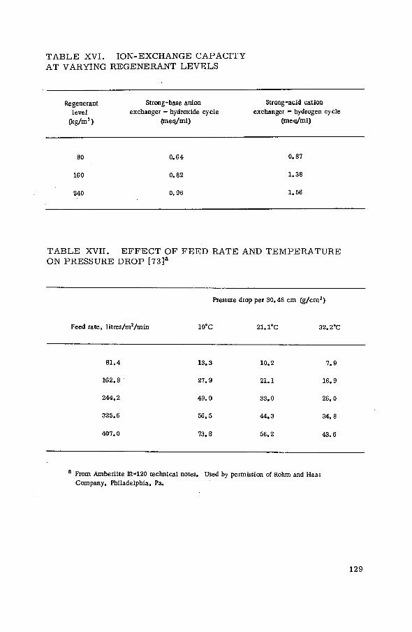
T A B L E XVI. ION-EXCHANGE CAPACITY AT VARYING REGENERANT LEVELS
Régénérant Strong-base anion Strong-acid cation level exchanger - hydroxide cycle exchanger - hydrogen cycle
(kg/m 3 ) (meq/ml) (meq/ml)
80 0 . 6 4 0 . 8 7
160 0 . 8 2 1 . 3 8
240 0 . 9 6 1 .56
TABLE XVII. E F F E C T OF F E E D RATE AND TEMPERATURE ON PRESSURE DROP [73]a
Pressure drop per 30.4Í Î cm ( g / c m 2 )
Feed rate, litres/m 2 /min 10°C 21.1°C 32.2°C
8 1 . 4 1 3 . 3 1 0 . 2 7 . 9
1 6 2 . 8 2 7 . 9 2 1 . 1 1 6 . 9
2 4 4 . 2 4 9 . 0 3 3 . 0 2 6 . 0
3 2 5 . 6 5 6 . 5 4 4 , 3 3 4 . 8
4 0 7 . 0 7 3 . 8 5 6 . 2 4 3 . 6
a From Amberlite Ж-120 technical notes. Used by permission of Rohm and Haas Company, Philadelphia, Pa.
129
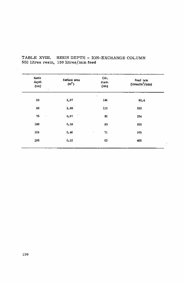
T A B L E XVIII. RESIN DEPTH - ION-EXCHANGE COLUMN 500 l i t res resin, 150 l i t r e s / m i n feed
Resin . , Col. „ , . . Surface area Feed rate
depth , 2 . diam. , , , . . (cm) <Ш > (cm) (litres/m /min)
3 0 1 . 6 7 146 9 0 . 4
5 0 1 . 0 0 113 150
75 0 . 6 7 92 2 2 4
100 0 . 5 0 8 0 3 0 0
125 0 . 4 0 71 375
150 0 . 3 3 62 4 6 5
130
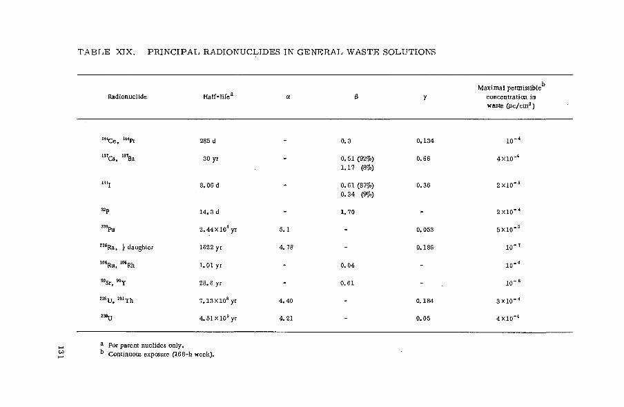
T A B L E XIX. PRINCIPAL RADIONUCLIDES IN G E N E R A L WASTE SOLUTIONS
Radionuclide H a l f - l i f e a a e У
M a x i m a l permissible1 5
concentrat ion in waste ( j J c / c m 3 )
1 4 4 C e , 1 4 4 Pr 285 d - 0 . 3 0 . 1 3 4 io-4
I 3 7 Cs, 137Ba 30 yr - 0. 51 (92%) 1 . 1 7 ( Щ
0 . 6 6 4 X 1 0 " 4
13 lj 8 . 0 6 d - 0 . 6 1 (87%) 0 . 3 4 (9%)
0 . 3 6 2 X 1 0 " 5
32p 1 4 . 3 d - 1 . 7 0 - 2 X l O " 4
2 3 9Pu 2 . 4 4 X 1 0 4 yr 5 . 1 - 0 . 0 5 3 5 X 1 0 " 5
2 2 6 Ra, 1 daughter 1622 yr 4 . 7 8 - 0 . 1 8 6 1 0 " 7
1 0 6 Ru, 1 0 6 Rh 1 . 0 1 yr - 0. 0 4 - 1 0 - 4
9 0Sr, 9 0 Y 2 8 . 6 yr - 0 . 6 1 • - 1 0 " 6
235 y 231 Xh 7 . 1 3 Х 1 0 8 yr 4 . 4 0 - 0 . 1 8 4 3 X 1 0 - 4
238ц 4 . 5 1 X 1 0 9 yr 4 . 2 1 - 0 . 0 5 4 X 1 0 ' 4
a For parent nuclides only , k Continuous exposure ( 1 6 8 - h week) .

T A B L E X X . EXCHANGERS IN USE F O R SEPARATION O F S P E C I F I C RADIONUCLIDES
Radionuclide Exchanger T o t a l capac i ty Remarks
1 3 7Cs, 1 3 7 Ba Cl inopt i lo l i te 1 . 5 - 1 . 7 m e q / g [ 7 4 - 7 6 ] Potassium h e x a c y a n o - 6 . 0 m e q / g [ 7 7 ] cobal t (II) ferrate II
V e r m i c u l i t e 1 . 0 0 - 1 . 5 0 m e q / g [ 6 4 , 7 8 , 7 9 ]
Strong acid -weak base synthetic resins
A c i d - 2 . 5 m e q / m l [ 8 0 ] Cols .
Base 1 . 9 m e q / m l Operated in series
Fi l trol i t 0 . 2 5 m e q / m l
Synthet ic zeol i tes 1 . 0 - 2 . 0 m e q / g
[ 8 1 ] C o m m e r c i a l s i l i ca te minera l
[82]
P h e n o l i c - c a r b a x y l i c cat ion resins
1 . 2 - 2 . 4 m e q / m l [ 7 0 ]
T i tan ium phosphate (Abeden T i - A )
7 . 5 m e q / g [61 , 8 3 ]
Ammonium m o l y b d o - 0 . 7 m e q / g phosphate
[ 6 3 ]
Tuf f 3 6 - 1 3 2 m e q / 1 0 0 g [ 8 4 ]
Mixed fission Synthet ic resins; S e e T a b l e s X a - c , products strong and weak cat ion Х П а - d
and anion
[ 8 5 ]
°Sr , M Y Synthet ic strong acid
c a t i o n - e x c h a n g e resins See T a b l e s X a - c [25 , 8 5 ]
Synthet ic zeol i tes Cl inopt i lo l i te
1 . 0 - 2 . 0 m e q / g [82]
[74 , 7 5 ]
132

T A B L E X X I . R E S E A R C H R E A C T O R S U S I N G I O N - E X C H A N G E W A T E R T R E A T M E N T [20]
Nominal Water treatment
power
MOATA Australia (Lucas Heights) 10 kW MB&10 |im filter
BR-2 Belgium (Mol) 50 MW Demineralizer 11SNR Belgium (Ghent) 150 kW MB
IRT-Sofia Bulgaria (Sofia) 2 MW Ion exchange
NRU Canada (Chalk River) 200 MW MB, filters NRX Canada (Chalk River) 40 MW MB, filters
WWR-C-Prague CSSR (Rez) 2 MW
DR-1 Denmark (Risif) 500 MW DR-1 Denmark (Risii) 5 MW
Aquilon France (Saclay) 1-100 W Ion exchange EL-1 (ZOE) France (Fontenay-aux-Roses) 150 kW Ion exchange
FR-2 Federal Republic of Germany (Karlsruhe) 12 MW Ion exchange, filters FRM Federal Republic of Germany (Munich) 1 MW
GRR Greece (Athens) 1 MW
WWR-C-Budapest Hungary (Budapest) 2 MW MB
APS ARA India (Trombay) 1 MW Ion exchange ZERLINA India (Trombaу) 100 W Ion exchange, filter
IRR Israel (Rehovot) 5 MW
AVOGADRO. RSI Italy (Sáluggia) 2 MW ISPRA-1 Italy (Ispra) 5 MW
UTRR Iran (Teheran) 1 MW
JRR-1 Japan (Tokai-Mura) 50 kW
HFR Netherlands (Petten) 20 MW Cation exchange, MB, i HOR Netherlands (Delft) 100 kW
JEEP Norway (Kjeller) 450 kW Ion exchange, filters NORA Norway (Kjeller) 100 W
PARR Pakistan (Rawalpindi) 5 MW
PRR-1 Philippines (Diliman) 1 MW
WWR-C-Warsaw Poland (Swierk) 2 MW
JEN Portugal (Lisbon) 1 MW
WWR-C-Bucharest Romania (Bucharest) 2 MW
SAFARI South Africa (Pelindaba) 20 MW Demineralizer, filters
R-O Sweden (Studsvik) 50 W R - l Sweden (Stockholm) 600 kW MB
DIORIT Switzerland (Wiirenlingen) 20 MW MB, filters SAPHIR Switzerland (Würenlingen) 1 MW
TRR-1 Thailand (Bangkok) 1 MW MB, filters
TR-1 Turkey (K. Cekmece) 1 MW
WWR-C-Cairo UAR (Inshas) 2 MW
MERLIN UK (Aldermaston) 5 MW MB, filters
DIDO UK (Harwell) 15 MW Ion exchange
OWR USA (Los Alamos) 5 MW MB, filters HFIR USA (Oak Ridge) 100 MW Demineralizer, filters
ЮТ USSR (Moscow) 2 MW Ion exchange
WWR-M USSR (Leningrad) 10 MW Ion exchange, filter
Notes: MB = mixed bed ion exchanger; Demin. = demineralizer.
133

T A B L E XXII . ION-EXCHANGE T R E A T M E N T O F POWER REACTOR WATERS [90, 91]
Name Location Gross heat
output (MW) Water treatment
CANDU Canada (Douglas Point)
NPD Canada (Des Joachims)
KAHL/MAIN Federal Republic of Germany (Kahl /Main)
JPDR
EBWR
Japan (Tokai-Mura)
R - 3 / A D A M Sweden (Stockholm)
USA (Argonne)
693
60
45
65
100
Filters and ion exchangers
3 litres/s to one of two mixed bed ion exchangers Mixed bed demineralizers in by-pass lines
Purification by condensate demineralizer and c lean-up demineralizer
4 kg/s through 3 mixed bed exchangers
Prefilters, afterfilters, anion-exchange columns, mixed bed units (one with borate ions)
DRESDEN USA (Grundy County, 111.) 626 Mixed bed ion exchangers
134

T A B L E XXIII . ION E X C H A N G E IN WASTE T R E A T M E N T A T N U C L E A R E N E R G Y ESTABLISHMENTS [93]
Site Nation Type of waste Waste
nuclides Type of system
Type exchanger
Regen, or
disposal
Decon. factor (DF)
Volume reduction
factor (VRF)
Argonne USA laboratory MFP Single column, cation Syn. org. R 3 0 - 1 0 . Argonne USA Laboratory MFP One cat ion, one mixed bed Syn. org. R -
Hahn-Meitner Federal Republic of Germany Laboratory 1 3 1 Cs Single column, cation Nat. inorg. D 10 5 1600
Hahn-Meitner Federal Republic of Germany Laboratory MFP Cation, anion & mixed bed column Syn. org. R - •
Harwell UK General MFP Lining of centrifuge Vermiculite D 1 0 - 2 0
Harwell UK General MFP Cols: Cat ion-* Anion-»Cation-Anion Syn. org. R 1 0 0 - 5 0 0
Idaho Falls USA Chemical 9 0 Sr and Four parallel columns of Nat. inorg. D 9°Sr-200 800
processing 137 Cs 2 cols in series
JEN Spain General MFP Cation, anion columns Syn. org. R - -
K j e l l e r Norway General MFP Cation, anion columns Syn. org. R 10 3 2 0 - 1 0 0
Lawrence USA General MFP Columns - vary Syn. org. D - -
Los Alamos USA General MSr 2 cation cols in series Syn. org. R 3 0 - 6 0 1 0 s
Mol Belgium General MFP Cation, anion col Syn. org. R 2 - 1 0 -
Mol Belgium General MFP Lining of centrifuge Syn. org. D -
Moscow USSR General MFP Serial cat ion, anion cols Syn. Org. R - • -
Pelindaba South Africa General MFP Mixed bed column Syn. org. D - • -
Pelindaba South Africa General MFP Mixed bed column Syn. org. - -
Fetten Netherlands General mC$ 2 cation cols R 100 -
Savannah River USA Evaporator 1 3 7 Cs , Cation-exchange column Syn. zeolites D 200 ( o t C J ) 4000
overheads
Savannah River USA Reactor tube MFP Mixed bed column Syn. org. R - -
Disassembly basin
Takai -Mura Japan General MFP Membrane - * mixed bed column Syn. org. R 450 -
Notes: M F P = mixed fission products; Syn. org. = synthetic organic resins; Nat. inorg. - natural inorganic resins.

T A B L E XXIV. CLASSIFICATION OF NUCLIDES F O R TRANSPORT PURPOSES
Nuclide Group Nuclide Group
1 4 4 C e and ш Р г IV 239Pu I
1 3 7Cs I V Z2fca I
131 j Ш 106 Ru III
M i x e d fission products I I 9 0 Si 11
32p I V
238ц III
90y IV
136

TABLE XXV. AVERAGE PRICES OF COMMON ENGINEERING MATERIALS, OCTOBER 1966, USA
Mater ia l Cost /kg (US J )
Acry l i c 1 . 01 Aluminium 1 . 0 1 Aluminium alloys 0 . 6 2
Austinitic stainless 0 . 8 4 - 1 . 3 2
Butadiene - a c r y l i c rubber 1 . 0 1 - 1 . 5 0 Butadiene - styrene rubber 0 . 3 1 - 0 . 7 7 Butyl rubber 0 . 5 1 - 0 . 6 6 Carbon steel 0 . 084 CFE-fluorocarbon 1 5 . 40 - 1 8 . 70
Chromium 2 . 88
C o m m e r c i a l bronze 1 . 2 1
Epoxy, liquid resins 1 . 0 6
Epoxy, solid resins 1 . 1 7
Ferri t ic stainless 0 . 68 - 0 . 9 0 Hastelloy F 7 . 4 3 Hastelloy X 7 . 4 3 High-density polyethylene 0. 55
K e l F rubber 3 5 . 20
Lead 0 . 33
Low-density polyethylene 0 . 35 - 0 . 4 8
Manganese bronze 1 . 2 8
Martensi t ic stainless 0 . 59 - 0 . 7 9
Natural rubber 0 . 5 3 - 0 . 5 7
Neoprene rubber 0 . 81 - 1 . 6 5
Nickel 1 . 6 9
Pig iron 0 . 066
Polypropylene 0 . 53
Polystyrene 0 . 3 2
Polysulphide rubber 1 . 3 2 - 2 . 7 5
Polyvinyl chloride 0 . 5 5 - 0 . 6 8
S i l i cone bronze 1 . 3 6
S i l i cone plast ic 5 . 0 6 - 7 . 8 1
S i l i cone rubber 5 . 5 0 - 8 . 8 0
TFE-f luorocarbon 7 . 1 5 - 1 1 . 0 0
Urethane rubber 2 . 5 3 -• 3 . 6 3 Vinyls 0 . 5 3 - 1 . 0 1
Viton rubber 22 •28.60
Z i n c 0 . 31
137

T A B L E XXVI. UNIT OPERATING COST: WASTE TREATMENT BY ION EXCHANGE
°\o of t i m e Vol . treated Operating cost
in use annually ( m 3 ) per m 3 (US S)
Savannah River 90 1 5 1 4 0 0 . 7 9 a
3 785 2 . 1 2
Harwell 100 8 597 4 . 6 1 15 6 0 0 7 . 9 3
JAERI 2 0 4 0 0 3 6 . 5 0
a Does not include depreciat ion.
138

T A B L E XXVII. ANNUAL OPERATING COSTS: WASTE T R E A T M E N T B Y ION EXCHANGE
Harwell Savannah River 3 JAERI
Columns
( U S $ ) Centrifuge
( u s s )
Overheads (US 8)
Miscel laneous (US 8 )
Tokai -Mura (US 8)
C h e m i c a l s and supplies
4 3 6 8 . 0 0 1 4 6 . 0 0 7 0 0 0 . 0 0 10 0 0 0 . 0 0 8 3 0 . 0 0
Labour 16 6 1 0 . 0 0 4 2 0 . 0 0 5 0 0 . 0 0 8 0 0 . 0 0 1 4 6 0 . 0 0
Maintenance 1 5 8 8 . 0 0 1 1 2 0 . 0 0 5 0 0 . 0 0 8 0 0 . 0 0 1 4 0 . 0 0
Overhead 10 2 9 6 . 0 0 2 6 0 . 0 0 2 0 0 0 . 0 0 2 0 0 0 . 0 0 5 6 0 . 0 0
Uti l i t ies 4 6 2 . 0 0 - - - -
Depreciat ion 6 2 9 4 . 0 0 - - - -
T o t a l costs 39 6 1 8 . 00 4 7 6 0 . 0 0 11 0 0 0 . o o b 1 4 0 0 0 . 0 0 1 4 6 0 0 . 0 0
Vol . treated 8 597 m 3 600 m 3 1 5 1 4 0 m 3 3 785 m 3 4 0 0 m 3
a S a m e exchange columns for 2 main uses, k Does not include depreciat ion.


REFERENCES
[1] MILLER, D. , Power 99 (1965) 73-77. [2] WAY, J . T . , J .R . agrie. Soc. , Lond. 11 (1850) 313; 13 (1852) 123. [31 von LIEBIG, J . , Am. Chem. Pharm. 94 (1855) 373. [4] THOMPSON, H . S . , On the absorbent power of soils, J .R. agrie. Soc. , Lond. U_ (1850) 68. [5] KUNIN, R., Ion Exchange Resins, 2nd Ed., John Wiley and Sons, Inc., New York (1958). [6] LEMBERG, J . , Z . dt. geol. Ges. 22 (1870) 355; 28 (1876) 519. [7] WIEGNER, G. . J . Landwirt. 60 (1912) 111, 197. [8] HARM, F . , RÜMPLER, A., 5th Intern. Congr. Pure Appl. Chem., 1903. [9] PAULING, L. , The sizes of ions and structure of ionic crystals, J. Am. chem. Soc. 49 (1927) 765-90.
PAULING, L. , Proc. natn. Acad. Sci. USA 16 (1930) 123. [10] KELLEY, W.P. , Cation Exchange in Soils, Reinhold Publishing Corp., New York (1949). [11] HENDRICKS, S . В . , Lattice structure of clay minerals and some properties of clays, J . Geol. 50
(1942) 276-90. [12] GRIM, R. E., Modern concepts of clay materials, J . Geol. 50 (1942) 225-75. [13] FAVEJEE. J . c . L . , Z. Krist. 101 (1939) 259. [14] BACON, R.C. , A study of the laws governing the cation-exchanging properties of a precipitated
aluminum silicate, J . phys. Chem. 40 (1936) 747-61. [15] ADAMS, B.A-., HOLMES, E.L. , J . Soc. chem. Ind., Lond. 54 I T (1935). [16] D'ALELIO, G. , U.S. Patents 2, 366007 (Dec. 1944); 2, 366008 (Dec. 1944). [17] JUDA, W., McRAE, W.A., J . Am. chem. Soc. 72 (1950) 1044; U.S . Patent 2, 636851-52 (1953).
KRESSMAN, T . R . E . , Nature, Lond. 165 (1950) 568. [18] KUNIN, R., McGARVEY, F . X . , Ind. Engng Chem. £7^(1955) 565. [19] DAWSON, J . K . , SOWDEN, R.G. , Chemical Aspects of Nuclear Reactors, Vol.2, Water-Cooled
Reactors, Butterworths, London (1963). [20] INTERNATIONAL ATOMIC ENERGY AGENCY, Directory of Nuclear Reactors, Vols 2, 3, 5, 1959,
1960, 1964, respectively. [21] AYERS, J . A . , Treatment of radioactive waste by ion exchange, Ind. Engng Chem. 43 (1951)
1526-31. [22] RODGER, W.A. , FINEMAN, P. , A complete waste disposal system for a radiochemical laboratory.
Nucleonics 9 (1951) 50-61. [23] SWOPE, H.G. , ANDERSON, E.. Cation exchange removal of radioactivity from wastes. Ind. Engng
Chem. 47 (1955) 58. [24] RODGER, W.A. , FINEMAN, P. , SWOPE, H.G. , "Disposal of radioactive wastes at Argonne National
Laboratory", Proc. 8th Ind. Waste Conf.,Purdue Univ., USA (1953) 474-91. [25] HUTCHINSON, J . P . , CHRISTENSON, C . W . , Treatment of radioactive wastes by chemical precipitation
and ion exchange at Los Alamos, New Mexico, TID-11048 (1960). [26] EMELITY, L .A. , CHRISTENSON, C .W. , Program and procedures for control of radioactive wastes at
Los Alamos, LADC-7711 (1966). [27] BOLSHAKOV, K .A. , AVDONIN, A . T . , BORCHEV, V . T . , RAUZEN, F .U. . "Pilot plant for
decontaminating laboratory liquid wastes", 2nd Conf. peaceful Uses atom. Energy (Proc. Conf. Geneva, 1958) 18 UN, New York (1958) 127-32.
[28] YAMAMOTO, Y . , ITO, M . F . , ISH1HARA, T . , MITSUISHI, N.. SAKATA, S . , "Treatment of radio-active waste at Japan's Atomic Energy Research Institute", Proc. Scient. Conf. on the Disposal of Radioactive Wastes, Monaco J1 (1959) 525-33.
[29] DEJONGHE, P. , BAETSLE, L . , MOSSELMANS, G., "Treatment of radioactive effluents at the Mol Laboratories", 2nd Conf. peaceful Uses atom. Energy (Proc. Conf. Geneva, 1958) 18 UN, New York (1958) 68-75.
[30] BURNS, R.H., GLUECKAUF, E., "Development of a self-contained scheme for low-activity wastes", 2nd Conf. peaceful Uses atom. Energy (Proc. Conf. Geneva, 1958) 18 UN, New York (1958) 150-60.
[31] ROBERTS, J . T . , HOLCOMB, R.R., A phenolic resin ion exchange process for decontaminating low-radioactivity-level process water wastes, USAEC Rep. ORNL-3036 (Jun. 1961).
141

[32] ROBERTS, J . T . , Developments in continuous ion exchange for ЛЕС applications, USAEC Rep. ORNL-2504 (Jun. 1958). HIGGINS, I .R . , MESSING, A.R., Development of a continuous ion exchange process for the removal of high-purity cesium from alkaline water, USAEC Rep. ORNL-2491 (Oct. 1958).
[33] AMPHLETT, C . B . , McDONALD, L .A. , REDMAN, J . A . , Chemy Ind. (1956) 1314. [34] AMPHLETT, C . B . , McDONALD, L .A. , REDMAN, J . A. , J . inorg. nucl. Chem. 6 (1958) 220. [35] AMPHLETT, C . B . , 2nd Conf. peaceful Uses atom. Energy (Proc. Conf. Geneva, 1958) 28 UN,
New York (1958) 17. [36] KRAUS, K.A. , PHILLIPS, H.O., J . Am. chem. Soc. 78 (1956) 249, 694. [37] KRAUS, K.A. , CARLSON, T . A . , JOHNSON, J . S . . Nature, Lond. 177 (1956) 1128. [38] KRAUS, K.A. , 2nd Conf. peaceful Uses atom. Energy (Proc. Conf. Geneva, 1958) 28 UN,
New York (1958) 3 . [39] GLUECKAUF, E., Atomic Energy Waste, Butterworths, London and Interscience Pub. Inc. , New York
(1961). [40] SEAL, M . S . , PECSOK, D.A. , Preliminary laboratory evaluation of an electrodialytic method for the
treatment of radioactive waters, CF-55-5-171 (1955). [41] ITO, M. , NISHIDOI, M. , Treatment of radioactive waste with ion exchange membrane electrodialyzer,
JAERI-1012 and AEC-tr-5079 (1962). [42] KUNIN, R., Ion Exchange Resins, 2nd Edn, John Wiley & Sons, Inc. New York (1958). [43] KUNIN, R., Elements of Ion Exchange, Reinhold Pub. Corp.. New York (1960) 12. [44] DIAMOND ALKALI CO., Western Div., Duolite Ion-Exchange Manual (1960) 19. [45] HELFFERICH, F . . Ion Exchange, Ch. 5, McGraw-Hill Book Co., New York (1962). [46] MYERS, G.E. , BOYD, G.E. , J . phys. Chem. 60 (1956) 521. [47] KUNIN, R., Elements of Ion Exchange, Reinhold Pub. Corp., New York (1960) 12-13. [48] DOW CHEMICAL CO., Dowex: Ion Exchange (1964) 22. [49] KUNIN, R., Elements of Ion Exchange, Reinhold Pub. Corp., New York (1960) 16, 17. [50] HELFF ERICH, F . . Ion Exchange, McGraw-Hill Book Co., New York (1962) 285. [51] HELFF ERICH, F . , Ion Exchange, McGraw-Hill Book Co. , New York (1962) 103, 104. [52] KUNIN, R., Elements of Ion Exchange, Reinhold Pub. Corp., New York (1960) 22-24. [53] HELFF ERICH, F. , Ion Exchange, McGraw-Hill Book Co., New York (1962) 14. [54] AMES, L .L . , Jr . , Synthesis of a clinoptilolite-like zeolite, HW-SA-2940 (1963). [55] HADEN, W.H., Jr., The use of inorganic exchange materials for radioactive waste treatment,
TID-7644 (1962). [56] ROCCO, G. G. , WEINER, J . R . , CAL, J . P. , The ion exchange properties of cerium (IV) compounds,
AF CRL-64-1018 (1964). [57] KUNIN, R., Elements of Ion Exchange, Reinhold Pub. Corp., New York (1960) 34. [58] FISHER, G . T . , THREADGILL, W.D., Radiation stability and inorganic radiochemistry, ТЮ-21385
(1964). [59] NATER, K.A. , Irradiation damage in ion exchange materials, NP-9805 (1959). [60] KATZ, H., ROTHBART, M. . Decontamination of Savannah River waste supernate by ion exchange,
BNL-853 (1964). [61] BALON, G., BEADET, C . A . , PIRET, J . , A new inorganic ion exchanger for the separation of
cesium from high level radioactive wastes, Euro Nuclear, 2 (1966). [62] BAETSLE, L. , VANDEYCK, D., HUYS, D. , GUERY. A., The use of inorganic ion exchangers in
acid medium for the recovery of Cs.and Sr from reprocessing solutions, 3rd int. Conf. peaceful Uses atom. Energy (Proc. Conf. Geneva, 1964) 10 UN, New York (1964) 580.
[63] SMIT, J . van R., The AMP process for caesium separation. 1. Adsorption of caesium on ammonium-12-molybdophosphate, AERE-R-3884 (1961).
[64] PROUT, W.E., RUSSELL, E.R., GROH, H. J . , Ion exchange adsorption of cesium by potassium hexacyanocobalt II ferrate III, CONF-179-1 (1963).
[65] SUGIMOTO, S . , ISHIHARA, T . , "Treatment practices of low and intermediate level radioactive wastes at the Japan Atomic Energy Research Institute", Practices in the Treatment of Low- and Intermediate-Level Radioactive Wastes (Proc. IAEA-ENEA Symp. Vienna, 1965) IAEA, Vienna (1966)' 207-22.
[66] STRAUB, C. P., Low-Level Radioactive Wastes: Their Treatment, Handling and Disposal, USAEC, Div. of Tech. Inf. (1964).
[67] EDISON ELECTRIC INSTITUTE, Radioactive Waste Handling in the Nuclear Power Industry (1960). [68] INTERNATIONAL ATOMIC ENERGY AGENCY, Technology of Radioactive Waste Management Avoiding
Environmental Disposal, Technical Reports Series No.27, IAEA, Vienna (1964).
142

[69] ROBERTS. J. T . , Development in continuous ion exchange equipment for AEC applications, ORNL-2504 '(1958).
[70] BLANCO, R.E., e t a l . , "Recent developments in treating low-and intermediate-level radioactive waste in the United States of America", Practices in the Treatment of Low- and Intermediate-Level Radioactive Wastes (Proc. IAEA-ENEA Symp. Vienna, 1965) IAEA, Vienna (1966) 793-839.
[71] KUNIN, R., Applications of Ion Exchange 2, Introductory Remarks (continued). Amber Hi-Lites, Rohm & Haas Co. (1966).
[72] HELFFERICH, F . , Ion Exchange, McGraw-Hill Book Co . , New York (1962) 427. [73] ROHM & HAAS Co., Amberlite IR-120, Amberlite Ion Exchange Resins, IE-54-60 (1966) (Converted to
metric system).
[74] POPOVICH, R.P. , Ion exchange recovery of cesium from alkaline supernatant waste - Scale-up studies, HW-83461 (1964).
[75] MATHERS, W.G., WATSON, L .C . , A waste disposal experiment using mineral exchange on clinoptilolite, CRCE-1080 (1962).
[76] AMBERSON, C . B . , RHODES, D.W., "Treatment of intermediate- and low-level radioactive wastes at the National Reactor Testing Station", Practices in the Treatment of Low- and Intermediate-Level Radioactive Wastes, (Proc. IAEA-ENEA Symp. Vienna, 1965), IAEA, Vienna (1966) 419-37.
[77] KVAM, D. J . , "Waste management practices at Lawrence Radiation Laboratory, Livermore", ibid., 3 -16 .
[78] BURNS, R.H., CLARKE, J .H . , WRIGHT, T . D . , MYATT, J .H. , "Present practices in the treatment of liquid wastes at the Atomic Energy Research Establishment, Harwell", ibid., 17-29.
[79] GRIM. R.E. , Clay Mineralogy, McGraw-Hill Book Co.. Inc., New York (1953). [80] BURNS, R.H., CLARKE, J .H . , WRIGHT, T . D . , "Filtration and ion-exchange plants in use at the
Atomic Energy Research Establishment, Harwell", Practices in the Treatment of Low- and Intermediate-Level Radioactive Wastes (Proc. IAEA-ENEA Symp. Vienna, 1965), IAEA, Vienna (1966) 223-54.
[81] LEVI, H.W., MELZER, H., "Some recent improvements in the low-level liquid effluent treatment process", ibid., 355-70.
[82] GIRDLER, Ч.М., "Handling of low- and medium-level liquid waste at the Savannah River Plant", ibid., 477-96.
[83] LOP EZ-M ENCUERO, E., "Research and development work on the treatment of low- and medium-level wastes in.the ENEA countries", ibid., 869-900.
[84] DLOUHY, Z. , Classification of the properties of pyroclastic rocks for uptake of fission products, UJV-951-63 (1963).
[85] EMELITY,, L .A. , CHRISTEN SON, C .W. , KLINE, W.H., "Operational practicesin the treatment of low-and intermediate-level radioactive wastes: Argonne and Los Alamos Laboratories, United States of America", Practices in the Treatment of Low- and Intermediate-Level Radioactive Wastes (Proc. IAEA-ENEA Symp. Vienna. 1965), IAEA, Vienna (1966) 187-205.
[86] SWOPE, H.G., "Treatment of radioactive wastes", Ch. 17, Ion Exchange Technology, Academic Press, Inc . . New York (1956).
[87] ROHDE, K. , Argonne National Laboratory, ANL-4820 (1952) 118. [88] MATER. DES. ENGNG, Materials Selector Issue (1966). [89] MAWSON, C . A . , personal communication, 15 Aug. 1966. [90] INTERNATIONAL ATOMIC ENERGY AGENCY, Directory of Nuclear Reactors 1_ (1959) ; 4 (1962). [91] INTERNATIONAL ATOMIC ENERGY AGENCY. Operating Experience with Power Reactors 1. (1963). [92] LEVI, H.W., personal communications, 16 Aug. 1966 and 30 Sept. 1966. [93] INTERNATIONAL ATOMIC ENERGY AGENCY, Practices in the Treatment of Low- and Intermediate-
Level Radioactive Wastes (Proc. Conf. Vienna, 1965) IAEA, Vienna (1966). [94] BURNS, R.H., personal communication, 25 Aug. 1966. [95] RHODES, D.W. , WILDING, M.W., Decontamination of radioactive effluent with clinoptilolite,
IDO-14657 (1965). [96] VANDEVOORDE, N., personal communication, 31 July 1966. [97] VERKERK, В. , SMEETS, L., personal communication, Aug. 1966. [98] GIRDLER, R.M. , personal communication, 26 Sept.1966. [99] ISHIHARA, T . , personal communication, Aug. 1966.
[100] HIESTER, N.K. , COHEN, R.K. , PHILLIPS, R .C. , Chem. Engng Prog. Symp. Ser. 50 14 (1954) 23. [101] DOWNING, D.G. , Calculating minimum-cost ion-exchange units, Chem. Engng 72 25 (1965) 170-176.
143

BIBLIOGRAPHY
AMES, L .L . , Jr . , Zeolitic extraction of cesium from aqueous solutions, USAEC Rep. HW-62607 (1959).
AMES, L. L., Jr . , Strontium and cesium loading characteristics of Decalso, Linde 4A and clinoptilolite columns, USAEC Rep. HW-70768 (1961).
AMES, L .L . , Jr . , Synthesis of a clinoptilolite-like zeolite, USAEC Rep. HW-SA-2940 (1963).
AMES, L .L . , Jr . , KNOLL, K .C . , Loading and elution characteristics of some natural and synthetic zeolites. USAEC Rep. HW-74609 (1962).
AMPHLETT, C . B . , Inorganic Ion Exchangers, Elsevier Pub. Co. , Amsterdam (1964).
BAERTSCHI, P. , et a l . . The methods and equipment for the treatment of liquid waste in the hot laboratory at Wiirenlingen (Switzerland), Rep. EIR-24 (1962).
BAETSLE, L. , Study of the fixation and migration of radioactive cations in a natural ion exchanger, USAEC Transi. AEC-TR-3949 (1959).
BAKER, B .L . , WILSON, Т . Н . , Inorganic sorbents, USAEC Rep. TID-20980, Part I (1964).
BENSON, D.W., Mineral adsorption of radionuclides in reactor effluent, USAEC Rep. HW-69225 (1961).
BERRY, L . G . , MASON, В., Mineralogy, W.H. Freeman and Co. , San Francisco (1959).
Bettis Atomic Power Lab., Reactor technology, USAEC Rep. WAPD-BT-23 (1961).
BRANDT, H.L. , Development in continuous ion exchange contactors - a progress report, USAEC Rep. HW-77805 (1963).
CRAVEN, F . J . , Investigation of methods for radioactive resin, disposal, USAEC Rep. AECU-4171 (1959).
CLARKE, J .H . , WRIGHT, T . D . , BERRYMAN, R.J. , Investigations into the use of a centrifuged bed of vermiculite for the decontamination of radioactive effluent, UKAEA Rep. AERE-R-4314 (1963).
CLARKE, J . H . , et a l . . Investigations into the use of ion exchange resins for the decontamination of radio-active effluent, UKAEA Rep. AERE-R- 4905 (1965).
DAVIS, T . F . , Radioactive waste processing and disposal - A literature search, USAEC Rep. TID-3555 (1960) and TID-3555 (Suppl. 1) (1962).
DAWSON, J . K . , SOWDEN, R.G., Chemical Aspects of Nuclear Reactors, Butterworths, London (1963).
DEJONGHE, P. , BAETSLE. L., Ion exchange and adsorption on ligneous material, TID-7621 (1959).
DÉMIER, W.V. , Dehydration of inorganic ion exchange media, USAEC Rep. HW-78893 (1963).
DEMIER, W.V. , Fixation of radioactive fission products on inorganic ion exchange media, USAEC Rep. HW-SA-3233 (1963).
DESROSIERS, P .E . , Water demineralization and decontamination studies utilizing electrodialysis, USAEC Rep. ERDL-1671-Tr (1961).
DIAMOND ALKALI CO., Duolite Ion Exchange Manual (1960).
DOW CHEMICAL CO., Dowex: Ion Exchange (1964).
FROST, C .R . , The fixation of caesium on Australian minerals. P a r t i . Vermiculite minerals (AAEC-TM-205); Part 2. Zeolite minerais (AAEC-TM-206) (1963).
GRIM. R.E., Clay Mineralogy, McGraw-Hill Book Co., Inc., New York (1953).
GRIMMETT, E .S . , DENEVERS, N.. Solids flow control for a pulsed solids-liquid contactor, USAEC Rep. IDO-14648 (1965).
HANCHER, C.W. , A comparison of fixed and moving bed ion-exchange, USAEC Rep. CF-58-8-53 (1958).
144

HELFF ERICH, F . , Ion Exchange, McGraw-Hill Book Co., Inc., New York (1962).
HIGGINS, I .R . , PHILLIPPI, C . G . , JONES, J . D . , Development of a process for continuous phenolic ion exchange treatment of alkaline intermediate radioactive-level waste, USAEC Rep. ORO-604 (1963).
HOLCOMB, R.R., ROBERTS, J . T . , Low-level waste treatment by ion exchange. II. Use of a weak-acid, carboxylic-phenolic ion-exchange resin, USAEC Rep. ORNL-TM-5 (1961).
HOLCOMB, R.R., ROBERTS, J . T . , A phenolic resin ion exchange process for decont. low-radioactive-level process water wastes, USAEC Rep. ORNL-3036 (1961).
INTERNATIONAL ATOMIC ENERGY AGENCY. Directory of Nuclear Reactors 1. (1959), 2 (1959), 3 (1960), 4 (1962), 5 (1964).
INTERNATIONAL ATOMIC ENERGY AGENCY, Disposal of Radioactive Wastes 1, IAEA, Vienna (1959).
INTERNATIONAL ATOMIC ENERGY AGENCY, The Management of Radioactive Wastes Produced by Radioisotope Users, Safety Series No. 12, IAEA, Vienna (1965).
INTERNATIONAL ATOMIC ENERGY AGENCY, Operating Experience with Power Reactors 1 (Proc. Conf. Vienna, 1963) IAEA, Vienna (1963).
INTERNATIONAL ATOMIC ENERGY AGENCY, Practices in the Treatment of Low- and Intermediate-Level Radioactive Wastes (Proc. IAEA-ENEA Symp. Vienna, 1965) IAEA, Vienna (1966).
INTERNATIONAL ATOMIC ENERGY AGENCY, Radioactive Waste Disposal into the Ground, Safety Series No. 15, IAEA, Vienna (1965).
INTERNATIONAL ATOMIC ENERGY AGENCY, Regulations for the Safe Transport of Radioactive Materials, 1964 Rev. Ed., Safety Series No. 6, IAEA, Vienna (1965).
JACOBS, D . G . , Cesium exchange by vermiculite, USAEC Rep. CF-61-9-31 (1961).
JAMISON, D . K . , et a l . . The use of inorganic exchange materials for radioactive waste treatment, USAEC Rep. TID-7644 (1963).
KADOYA, S . , HORIOKA, M. , "Decontamination of Radioactive Water with Domestic Clay Minerals", 2nd Rad. Res. Mtg in Science and Engng (1965).
KAHN, M. , LAWSON, K., JONES, K . J . , Ion-exchange resins (A bibliography of unclassified references), USAEC Rep. TID-4500 (1957).
/
KING, L . J . , ICHIKAWA, M., Pilot plant demonstration of the decontamination of low-level process wastes a recycle scavenging-precipitation ion-exchange process, USAEC Rep. TID-4500 (46th Ed.) (ORNL-3863) (1965).
KRAWCZYNSKI, S . , Studies on the deactivation of radioactive effluents by electrodialysis, USAEC Transi. NP-TR-863 (1961).
KUNIN, R., Ion Exchange Resins, John Wiley & Sons, Inc. , New York (1958).
KUNIN, R., Elements of Ion Exchange, Reinhold Pub. Corp., New York (1960).
LARSEN, E .M. , VISSERS, D.R. , J . phys. Chem. 64 (1960) 1732.
LEWIS, R.E. , BUTLER, T . A. . LAMB, E„ Recovery of 137Cs from fission-product wastes and transport by an aluminosilicate ion exchanger, USAEC Rep. ORNL-3765 (1965).
LINDSAY, W. T . , ABRAMS, C . S . , Ion exchange removal of fission products from high purity water. Develop ment work associated with the PWR radioactive waste disposal system, USAEC Rep. WAPD-PWR-CP-2636 (1957).
MANDERSLOOT, W.G.B . , "The limitations of electrodialytic water desalting with permselective membranes and the requirements for electrodialytic equipment", 1st Int. Symp. on Water Desalination, Washington, D.C (1965).
MARHOL, M . , Ion exchangers. A survey of their characteristic properties, Chem. Listy 56 (1962) 728-762.
Materials in Design Engineering 64 5 (Mid-October 1966-67).
MATHERS, W.G. , Some properties of hydrogen-based clinoptilolite, AECL Rep. AECL-1670 (CRL-76) (1963).
145

MERCER, В. W., Adsorption of trace ions from intermediate level radioactive wastes by ion exchange, USAEC Rep. BNWL-180 (1966).
MERCER, B. W., Storage of long-lived fission products on alumino-silicate zeolites, USAEC Rep. RL-SA-58 (1965).
MICHAEL, N.. BELL, M., Evaluation of ion exchange resins for use in the Yankee Reactor, USAEC Rep. YAEC-115 (1959).
MINTZ, M.S . , Ind. Engng Chem. 12 6 (1963).
MURRAY, N.F. . Radioactive liquid waste handling and disposal at Chalk River, AECL Rep. CRIO-1194 (AECL-1975) (1964).
NACHOD, F . C . , SCHUBERT. J . . Ion Exchange Technology, Academic Press, Inc., New York (1956).
NANCOLLAS, G.H., Synthetic inorganic ion exchange materials, UKAEA Rep. AERE C/R 2755 (1959).
NELSON, J . L . , MERCER, B. W., Ion exchange separation of Cs from alkaline waste supernatant solutions, USAEC Rep. HW-76449 (1963).
NELSON, J . L . , ALK3RE, G . J . , MERCER, B.W., Inorganic ion exchange separation of Cs from Purex-type high-level radioactive wastes, USAEC Rep. HW-SA-2920 (1963).
NELSON, J . L . , AMES, L .L . , MERCER, B.W., Characterization and Application of zeolites for radioactive waste treatment, USAEC Rep. HW-SA-3333 (1964).
NICHOLSON, G.A. , Continuous ion-exchange development, USAEC Rep. HW-62689 (1959).
OSBORN, G.H., Synthetic Ion-Exchangers, Chapman & Hall Ltd., London (1955).
PERMUTIT CO. LTD., Investigations into the use of ion exchange resins for the decontamination of radioactive effluent. Parti . Laboratory trials, UKAEA Rep. AERE-R-3496 (1960).
PERRY, R.H., CHILTON, C.H. , MRKPATRICK, S .D. , Chemical Engineers' Handbook, McGraw-Hill Book Co., New York (1963).
RHODES, D.W., WILDING, M.W., Decontamination of radioactive effluent with clinoptilolite, USAEC Rep. IDO-14657 (1965).
R1MSHAW, S . J . . WINKLEY, D.C. , Removal of I31Cs, 90Sr, and 106Ru from ORNL plant wastes by sorption of various minerals, USAEC Rep. CF-60-4-17 (1960).
ROHM & HAAS Co., Amber Hi-Lites.
SAMMON, D . C . , WATTS, R.E., An experimental study of electrodeionization and its application to the treatment of radioactive wastes. UKAEA Rep. AERE-R-3137 (1960).
SCHOENFELD, I . , Preparation and properties of some synthetic inorganic anion exchangers, USAEC Rep. 1A-720 (1962).
SKARPELOS, J . M . , Progress in treatment of radioactive condensate waste, USAEC Rep. HW-79174 (1963).
SOCIETY OF CHEMICAL INDUSTRY, Proc Conf.. on Ion Exchange and its Applications, London Univ., 1954, Soc. of chem. Ind. (1955).
SONNEN. M.B. , RAY, A.D. . A Report on Small-Scale Decontamination of Radioactive Waters by Ion Exchange, Vanderbilt Univ., USA (1963).
TAMURA, T . , Development and application of mineials in radioactive waste disposal, USAEC Rep. ORNL-P-1811 (1966).
THOMAS, K . T . , JACOBS, D.G. , TAMURA, T . , STRUXNESS, E.G., Strontium sorption studies using naturally occurring ion exchange materials, USAEC Rep. CF-60-10-35 (1960).
UNITED NATIONS, 2nd Conf. peaceful Uses atorn. Energy (Proc. Conf. Geneva, 1958) ji, 9, 15, 18. 28, UN, New York (1958).
UNITED STATES ATOMIC ENERGY COMMISSION, Oak Ridge National Laboratory Chem. Div. annual progress rep. for period ending May 20, 1965, USAEC Rep. TID-4500 (43rd Edn) (ORNL-3832).
UNITED STATES ATOMIC ENERGY COMMISSION, Oak Ridge National Laboratory Chem. Tech. Div. annual progress rep. for period ending May 31, 1963, USAEC Rep. ORNL-3452 (1963).
146
UNITED STATES ATOMIC ENERGY COMMISSION, Oak Ridge National Laboratory Health Physics Div. annual progress rep. for period ending July 31, 1961, USAEC Rep. ORNL-2994 {i960). •
UNITED STATES ATOMIC ENERGY COMMISSION, Oak Ridge National Laboratory Health Physics Div. annual progress rep. for period ending July 31, 1961, USAEC Rep. TID-4500 (16th Edn, rev.) (ORNL-3189).
UNITED STATES ATOMIC ENERGY COMMISSION, Proc. Conf. on Ground Disposal of Radioactive Wastes, Berkeley, Cal . , 1959, USAEC Rep. TID-7621 (1961).
UNITED STATES ATOMIC ENERGY COMMISSION, Univ. of South Carolina Dept. of Chem. Engng Prog. Rep. No. 1„ Feb. 1, 1957 - Oct. 31, 1958. Part I. Adsorption of Ca and Sr on hydrous ferric oxide and limonite, USAEC Rep. TID-19164 (1958).
UNITED STATES GEOLOGICAL SURVEY, Water Supply Paper 1616, Ion Exchange Minerals and Disposal of Radioactive Wastes - A Survey of Literature (1962).
VAN ANTWERPEN, F . J . , Ion exchange, Chem. Engng Prog. Symp. Ser. 50 14 (1954) Am. Inst. Chem. Engng, New York (1954).
VORESS, H.E. , DAVIS, T . F . , HUBBARD, T . N . , J r . , Radioactive waste processing and disposal, a bibli-ography of selected report literature, USAEC Rep. TID-3311 (1958) and TID-3311.
WEBB, W.H., The separation of some of the radioactive fission products by electrodialysis, USAEC Rep. COO-770-12 (1964).
WHITNEY, D . C . , DIAMOND, R.M. , Ion exchange studies in concentrated solutions. 1. The alkali cations with sulfonic acid resin, USAEC Rep. UCRL-10595 (1962).
WILDING, M . W . , RHODES, D. W., Removal of radioisotopes from solution by earth materials from eastern Idaho, USAEC Rep. IDO-14624 (1963).
WILSON, J . R . , Demineralization by Electrodialysis, Butterworths, London (1960).
YAMAMOTO, Y . , Inter-Regional Advanced Training Seminar on Radioactive Waste Management, Session IX (b). Liquid Treatment (Ion Exchange) (1965).
ZARNOWIECKI, K. , KOSTYRKO, A., Study on removal of some radionuclides by sorption on peat, Instit. of Nucl. Res., Swierck, Otwock, Poland (NP-14662, 14668) (1963).
147

I A E A S A L E S A G E N T S
Orders for Agency publications can be placed with your bookseller or any of our sales
agents listed below :
A R G E N T I N A Comision Nacional de
Energía Atómica
Avenida del Libertador
General San Martin 8250
Buenos Aires • Suc. 29
A U S T R A L I A
Hunter Publications,
23 McKillop Street
Melbourne, C. l
A U S T R I A
Georg Fromme & Co.
Spengergasse 39
A-1050. Vienna V
B E L G I U M
Office international de librairie
30, avenue Marnix
Brussels 5
B R A Z I L
Livraria Kosmos Editora Rua do Rosario, 135-137
Rio de Janeiro
Agencia Expoente Oscar M. Silva
Rua Xavier de Toledo, 140-1® Andar
(Caixa Postal No. 5.614)
Sao Paulo
BYELORUSSIAN SOVIET SOCIALIST
REPUBLIC
See under USSR
CANADA
The Queen's Printer
Ottawa, Ontario
C H I N A (Taiwan)
Books and Scientific Supplies
Service, Ltd.,
P.O. Box 83
Taipei
CZECHOSLOVAK SOCIALIST REPUBLIC
S.N.T.L.
Spolena 51 Nove Mesto Prague 1
D E N M A R K
Ejnar Munksgaard Ltd.
6 Norregade
Copenhagen К
F I N L A N D
Akateeminen Kirjakauppa
Keskuskatu 2
Helsinki
F R A N C E
Office international de
documentation et librairie
48, rue Gay-Lussac
F-75, Paris 5 e
G E R M A N Y , Federal Republic of
R, Oldenbourg
Rosenheimer Strasse 145
8 Munich 8
H U N G A R Y
Kultura
Hungarian Trading Co, for Books
and Newspapers
P.O.B. 149
Budapest 62
I S R A E L
Heiliger and Co,
3 Nathan Strauss Street
Jerusalem
I T A L Y
Agenzia Editoriale Internazionale
Organizzazioni Universal» (A.E.I.O.U.)
Via Meravigli 16
Milan
J A P A N
Maruzen Company Ltd.
6, Tori Nichome
Nihonbashi
(P.O. Box 605)
Tokyo Central
M E X I C O
Librería Internacional
Av. Sonora 206
Mexico 11, D.F.
N E T H E R L A N D S
N.V. Martinus Nijhoff
Lange Voorhout 9
The Hague
NEW Z E A L A N D
Whitcombe & Tombs, Ltd.
G.P.O. Box 1894
Wellington, C. l

N O R W A Y . * ' . Johan .Grundt Tanum * 'Karl Johans gate 43 »•«
/ Oslo ' ' „
P A K I S T A N ' • _ • Karachi Education Society H ar oon» Chambers
, South Napier Road (P.O. Box No. 4866) Karachi 2 . • . .
.POLAND Osrodek Rozpowszechniana
* . Wydawnictw Naukowych ' vPo lska Akademia Nauk *
Paíac Kultury i Nauki ' * Warsaw
R O M A N I A ' Cartimex Rue A. Briand 14-18 • * Bucarest
SOUTH AFRICA* Van Schaik's Bookstore (Pty) Ltd. Libri Building
% Church Street , (P .O. Box 72U) . Pretoria
S P A I N Librería Bosch •Ronda de la ^Universidad 11 Barcelona
SWEDEN* C.E. Fritzes Kungl. Hovbokha'ndel Fredsgatan 2 Stockholm 16
S W I T Z E R L A N D Libra'irie Payot * * ,
4* Rue Grenus 6 w ь
,1211 Geneva 11
t u r k e y " ' Librairie Hachette * 469¿ Istiklâl Caddesi
« Beyoglu , Istanbul -, «»
UKRAINIAN SOVIET SOCIALIST REPUBLIC " •
-See under USSR
UNION OF SOVIET SOCIALIST * , REPUBLICS' . , ' \ Л
Mezhdunarodnaya Kniga Smolenskaya-Sennaya 32-34 Moscow G-200
UNITED KINGDOM OF GREAT BRITAIN AND NORTHERN IRELAND
Her Majesty 's Stationery Off ice P .O. Box 569 ( • * London, S .E.I
UNITED STATES OF AMERICA National Agency for, International Publ icat ions , Inc. 317 East 34th Street New Y o r k / N . Y . Í0016
V E N E Z U E L A -Sr. Braulio Gabriel Chacares' Gobernador a Candilito 37 ' Santa Rosalia . (Apartado Postal 8092) Caracas D ,F , , -
Y U G O S L A V I A * Jugoslovenska Knjiga . » Terazi je 27 * Belgrade
IAEA publications can also be purchased retail at the United Nations Bookshop at United Nations Headquarters, New York, at the news-stand at-the Agency ' s Head-quarters, Vienna, and 'at most conferences , symposia and seminars organized ,by the Agency . ' « *
In order to facilitate the distribution of its publ icat ions, the Agency is prepared Lo accept payment in UNESCO coupons or in l oca l currencies . ' - *
Orders and inquiries' from countries where sale's agents have not yet been appointed may be sent to :
• J Distribution and Sales Group, International AtomicvEnergy Agency , Karntner Ring 11, A-1010, Vienna I, Austria „

I N T E R N A T I O N A L A T O M I C E N E R G Y A G E N C Y V I E N N A . 1 9 6 7
P R I C E : U S $ 3 . 0 0 A u s t r i a n S c h i l l i n g s 7 8 . • ( £ 1 . 1 . 2 : F .Fr . 1 4 . 7 0 ; D M 1 2 . )