technical seminar for cathodic protection to gogc …. general_lightningprot_technical... ·...
TRANSCRIPT

Technical Seminar for Cathodic Protection
to GOGC Design Unit Specialists
Dr. Nick Kioupis, Cathodic & Lightning Protection
Section Head, DESFA

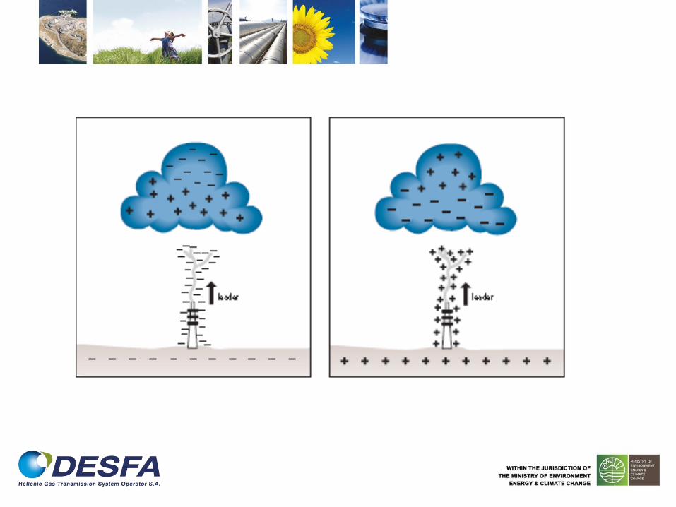
Downward Flash (cloud-to-earth lightning flash)

Upward Flash (earth-to-cloud lightning flash)

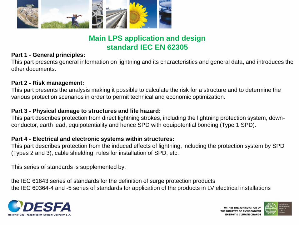
Part 1 - General principles:
This part presents general information on lightning and its characteristics and general data, and introduces the
other documents.
Part 2 - Risk management:
This part presents the analysis making it possible to calculate the risk for a structure and to determine the
various protection scenarios in order to permit technical and economic optimization.
Part 3 - Physical damage to structures and life hazard:
This part describes protection from direct lightning strokes, including the lightning protection system, down-
conductor, earth lead, equipotentiality and hence SPD with equipotential bonding (Type 1 SPD).
Part 4 - Electrical and electronic systems within structures:
This part describes protection from the induced effects of lightning, including the protection system by SPD
(Types 2 and 3), cable shielding, rules for installation of SPD, etc.
This series of standards is supplemented by:
the IEC 61643 series of standards for the definition of surge protection products
the IEC 60364-4 and -5 series of standards for application of the products in LV electrical installations
Main LPS application and design
standard IEC EN 62305
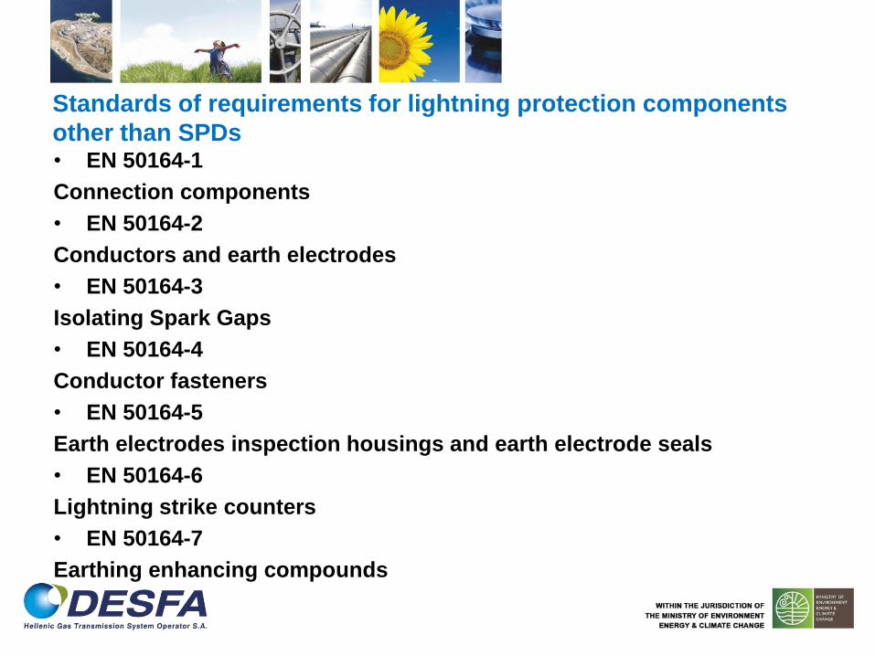
Standards of requirements for lightning protection components
other than SPDs
• EN 50164-1
Connection components
• EN 50164-2
Conductors and earth electrodes
• EN 50164-3
Isolating Spark Gaps
• EN 50164-4
Conductor fasteners
• EN 50164-5
Earth electrodes inspection housings and earth electrode seals
• EN 50164-6
Lightning strike counters
• EN 50164-7
Earthing enhancing compounds
Standards for testing SPDs
• SPDs for power lines
– EN IEC 61643-1 (2005)
– EN IEC 61643-11 (2002)
• SPDs for telecommunications/ signaling networks
– EN IEC 61643-21 (2001)
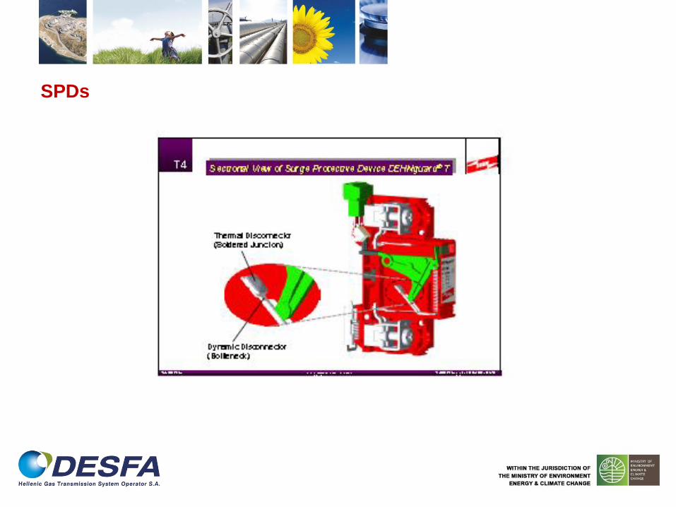
SPDs

SPDs

Standards for selection and installation of SPDs
• SPDs for power lines
– EN IEC 61643-12 (2006)
• SPDs for telecommunications/ signaling networks
– EN IEC 61643-22 (2006)

Inductance
V=l*L*di/dt
L (mH)=.2*l*(.5+loge(2*l/w+h))+.11*(w+h/l) for a flat conductor. l,w&h are measured in metres
L (mH) = .2*l*(loge(2*l/r –1) for a round conductor
.1mH/m
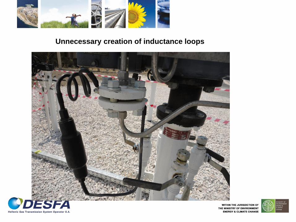
Unnecessary creation of inductance loops

Correct installation of spark gap
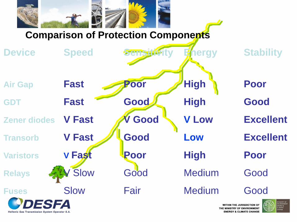
Device Speed Sensitivity Energy Stability
Air Gap Fast Poor High Poor
GDT Fast Good High Good
Zener diodes V Fast V Good V Low Excellent
Transorb V Fast Good Low Excellent
Varistors V Fast Poor High Poor
Relays V Slow Good Medium Good
Fuses Slow Fair Medium Good
Comparison of Protection Components
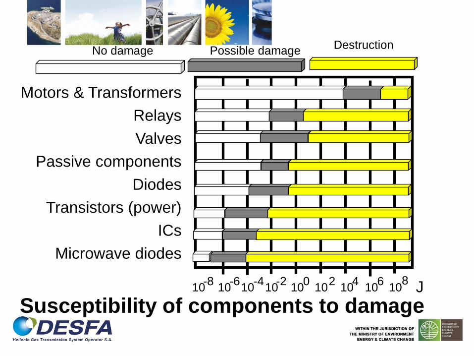
Susceptibility of components to damage
Motors & Transformers
Relays
Valves
Passive components
Diodes
Transistors (power)
ICs
Microwave diodes
10 10 10 10 10 10 10 10 10 -8 -6 -4 -2 0 2 4 6 8
J
No damage Possible damage Destruction

TV
Telephone Lines
400/230 V
Power Plant
110 kV
ABC Company
GSM phones lines
Τelecommunication line
Distance of damage by a lightning strike

Bldg. “A” Bldg. “B”
Data Line
200kV
Distance
15kV
100m
V = 12kV
3kV
500m
Voltage
Communication port damage

Direct strike to building
Bldg. “A” Bldg. “B”
Data Line
50%
50%
100kA
IEC61024
IEC61312
11kV
415v
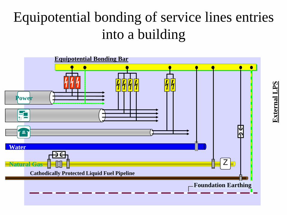
Equipotential bonding of service lines entries
into a building
Cathodically Protected Liquid Fuel Pipeline
Equipotential Bonding Bar
Water
Natural Gas
Power
Exte
rn
al
LP
S
Foundation Earthing
Z
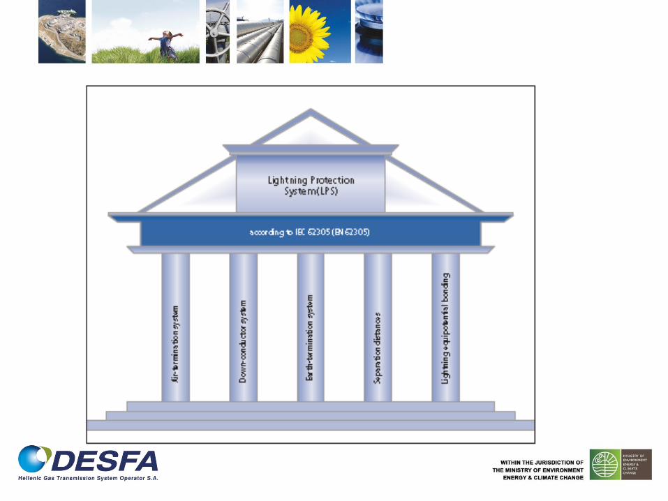
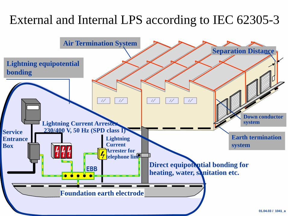
Air Termination System
01.04.03 / 1041_a
External and Internal LPS according to IEC 62305-3
Foundation earth electrode
EBB
Service Entrance Box
Direct equipotential bonding for heating, water, sanitation etc.
Lightning equipotential
bonding
Separation Distance
Down conductor system
Earth termination
system
Lightning Current Arrester 230/400 V, 50 Hz (SPD class I)
Lightning Current Arrester for telephone line
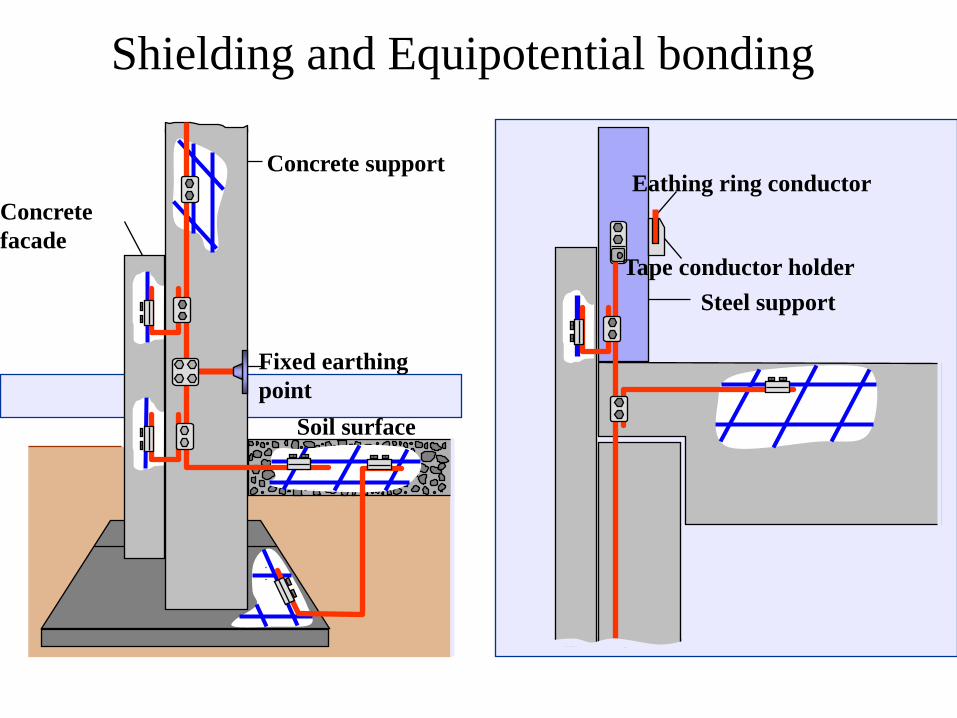
Concrete support
Concrete
facade
Fixed earthing
point
Soil surface
Eathing ring conductor
Steel support
Tape conductor holder
Shielding and Equipotential bonding
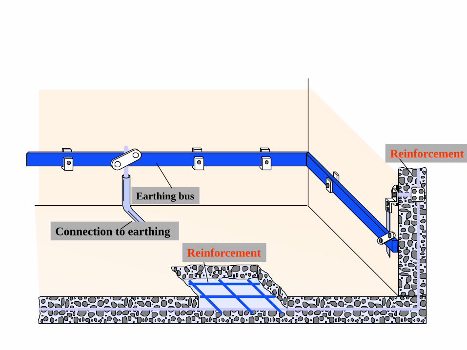
Earthing bus
Reinforcement
Reinforcement
Connection to earthing

Common earthing system
Incoming Surge SPD DC Power
To
distribution
earth
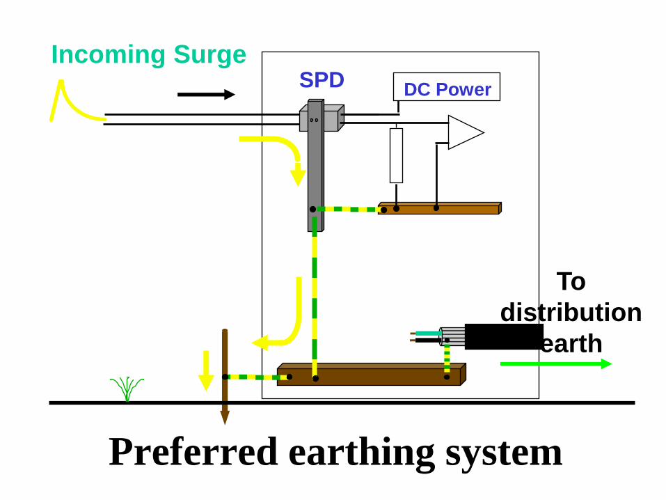
Preferred earthing system
Incoming Surge SPD DC Power
To
distribution
earth
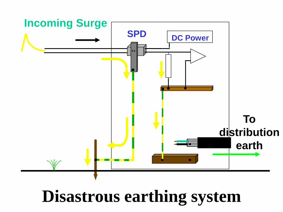
Disastrous earthing system
Incoming Surge SPD DC Power
To
distribution
earth
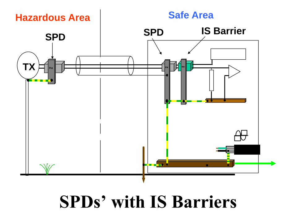
SPDs’ with IS Barriers
Hazardous Area
SPD IS Barrier
Safe Area
TX
SPD
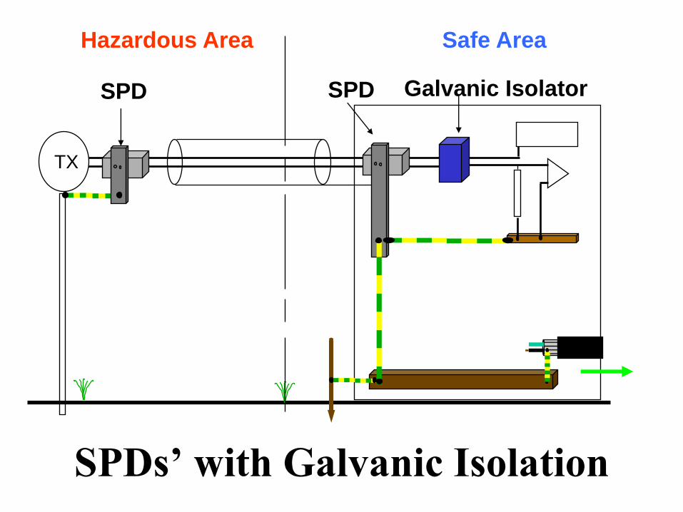
SPDs’ with Galvanic Isolation
Galvanic Isolator
Hazardous Area Safe Area
TX
SPD SPD