technical specifcation - manipur state power distribution ... · technical specifcation for 3-phase...
TRANSCRIPT

ANNEXURE-A
TECHNICAL SPECIFCATION
FOR
3-PHASE 4-WIRE CT OPERATED FULLY STATIC AMR COMPATIBLE TRI-VECTOR ENERGY METERS
FOR
DISTRIBUTION TRANSFORMERS

TECHNICAL SPECIFICATION FOR 3-PHASE 4-WIRE CT OPERATED FULLY STATIC AMR COMPATIBLE TRI-VECTOR ENERGY METERS
1.0 SCOPE
Design, manufacturing, testing, supply and delivery of AC, 3 Phase, 4 Wire, CT / PT (if
necessary) operated fully Static and AMR compatible Tri-Vector lag only Energy Meters for
measurement of different electrical parameters listed elsewhere in the document including
Active Energy (KWH), Reactive Energy (KVARH), Apparent Energy (KVAH) etc. The detail
scope is given below.
2.0 APPLICATION
On Distribution Transformers
3.0 STANDARDS TO WHICH METERS SHALL COMPLY Guidelines on “Data Exchange for Electricity Meter Reading, Tariff and Load Control – Companion Specification” enclosed with this document as annexure.
IEC 62056-21 Electricity metering: Data exchange for meter reading, tariff and load control-Part 21: Direct local data exchange
IEC 62056-31 Electricity metering: Data exchange for meter reading, tariff and load control - Part 31: Local Area Network data exchange
IEC 62056-61 Electricity metering: Data exchange for meter reading, tariff and load control-Part 61: Object identification system (OBIS)
IS-14697 Specification for AC Static Transformer operated Watt Hour & VAR-Hour meters (class 0.5S);
IS – 15959:2011 Data Exchange For Electricity Meter Reading, Tariff And Load Control – Companion Specification.
IEC 62052-11 Electricity metering equipment (AC) –General requirements, tests and test conditions -Part 11: Metering equipment;
IEC 62053-22 Electricity metering equipment (AC) –Particular requirements - Part-22: Static Meters for Active Energy (Class 0.5S);
IS-15707 Specification for Testing, evaluation, installation & maintenance of AC Electricity Meters-Code of Practice
The equipment meeting with the requirements of other authoritative standards, which ensure
equal or better quality than the standard mentioned above, also shall be considered; in case of
conflict the Guidelines on “Data Exchange for Electricity Meter Reading, Tariff and Load
Control – Companion Specification” enclosed with this document as annexure shall prevail
upon.
4.0 GENERAL TECHNICAL REQUIREMENTS
1 TYPE AMR Compatible Static, 3 Ph, 4 Wire Tri-Vector Energy Meter for Distribution Transformer
1

2 FREQUENCY 50 Hz ±5% 3 ACCURACY 0.5S
CLASS
4 SECONDARY Suitable for operation from 415 Volt Ph-Ph /or 240 Volt Ph-N
VOLTAGE
5 BASIC CURRENT -/5 Amps.
(Ib)
6 MAXIMUM 2.0 Ib; Starting and Short time current shall be as per IS-14697
CONTINUOUS
CURRENT
7 POWER The active and apparent power consumption, in each voltage
CONSUMPTION circuit, at reference voltage, reference temperature and
reference frequency shall not exceed 1. 5 W and 8 VA.
The apparent power taken by each current circuit, at basic
current, reference frequency and reference temperature shall
not exceed 1.0 VA
8 POWER FACTOR 0.0 Lag -Unity- 0.0 Lead
9 DESIGN Meter shall be designed with application specific integrated
circuit (ASIC) or micro controller; shall have no moving part;
electronic components shall be assembled on printed circuit
board using surface mounting technology; factory calibration
using high accuracy (0.05 class) software based test bench.
Assembly of electronic components shall be as per ANSI/IPC-
A-610 standard.
5.0 CONSTRUCTIONAL REQUIREMENT/ METER COVER & SEALING ARRANGEMENT
Wherever poly carbonate cover is specified, it shall conform to IS 11731 (FH-1category) besides
meeting the test requirement of heat deflection test as per ISO 75, glow wire test as per the
IS:11000 (part 2/SEC-1) 1984 OR IEC PUB,60695-2-12, Ball pressure test as per IEC-- 60695-
10-2 and Flammability Test As per UL 94 or As per IS 11731(Part-2) 1986.
5.1 CONSTRUCTION
The case, winding, voltage circuit, sealing arrangements, registers, terminal block, terminal
cover & name plate etc. shall be in accordance with the relevant standards. The meter should be
compact & reliable in design, easy to transport & immune to vibration & shock involved in the
transportation & handling. The construction of the meter should ensure consistence performance
under all conditions especially during heavy rains / very hot weathers. The insulating materials 2

used in the meter should be non-hygroscopic, non-ageing & have tested quality. The meter
should be sealed in such a way that the internal parts of the meter becomes inaccessible and
attempts to open the meter shall result in viable damage to the meter cover. This is to be
achieved by using continuous Ultrasonic welding on the Meter body or any other technology
which is either equally or more efficacious.
The meter should comply latest technology such as Microcircuit or Application Specific
Integrated Circuit (ASIC) to ensure reliable performance. The mounting of the components on
the PCB should compulsorily be Surface Mounted Technology (SMT) type. Power supply
component may be of PTH type. The electronic components used in the meter should be of high
quality and there should be no drift in the accuracy of the meter for at least ten years. The
circuitry of the meter should be compatible with 16 Bit (or better) ASIC with compatible
processor and meter should be based on Digital measuring and sampling technique.
The meter should be housed in a safe, high grade, unbreakable, fire resistant, UV stabilized, virgin
Polycarbonate casing of projection mounting type. The meter cover should be transparent, for easy
reading of displayed parameters, and observation of operation indicators. The meter base may or may
not be transparent, but it should not be black in colour. The meter casing should not change shape,
colour, size, dimensions when subjected to 200 hrs on UV test as per ASTMD 53. It should withstand
650 deg. C. glow wire test and heat deflection test as per ISO 75. The meter cover should be sealable to the meter base with at least 2 nos. seals.
The bidder shall submit relevant documents regarding the procurement of polycarbonate material. The polycarbonate material of only the following manufacturers shall be used.
a) G.E. Plastics : LEXAN 943A or equivalent for cover & Terminal cover/
LEXAN 503R or equivalent base.
b) BAYER : Grade corresponding to above
c) DOW Chemicals : -Do-
d) MITSUBISHI : -Do-
e) TEJIN : -Do-
f) DUPONT : -Do-
5.2 METER CASE AND COVER The meter should have a case, which can be sealed in such a way that the internal parts of
the meter are accessible only after breaking the seal and cover. This is to be achieved by
used of Ultrasonic Welding (Ultrasonically continuously welded at three sides so that the
cover cannot be separated from the basic without breaking/damaging the case & cover) or
any other technology which is either equally or more efficacious. In case, ultrasonic
welding using plate / strip is used the material of plate / strip should be same as that of
cover and base and the strip. The manufacturer’s logo should be embossed on the strip /
plate. The material of the meter body (case and cover) shall be of Engineering Plastic.
The meter cover should be fixed to the meter base (case) with Unidirectional Screws, so
that the same cannot be opened by use of screwdrivers. These unidirectional screws should
be covered with transparent caps, ultrasonically welded with the meter body and the screw
covers should be embedded in the meter body in a groove. 3

The meter shall withstand external magnetic influence as per latest amendments of CBIP Technical Report No.88.
5.3 TERMINAL BLOCK AND COVER : The terminals may be grouped in a terminal block having adequate insulating properties
and mechanical strength. The terminal block should be made from best quality non-
hygroscopic, flame retardant material (capable of passing the flammability tests) with
nickel plated brass inserts / alloy inserts for connecting terminals.
The terminals in the terminal block shall be of adequate length in order to have proper grip
of conductor with the help of screw adjustable metal plates to increase the surface of
contact and reduce the contact resistance. The screws shall have thread size not less than
M4 and head having 4-6mm. Diameters.
The screws shall not have pointed ends at the end of threads. All terminals and connecting screws and washers should be of tinned / nickel plated brass material.
The internal diameter of terminal hole should be minimum 5.5 mm. The holes in the insulating material shall be of sufficient size to accommodate the insulation of conductor
also.
The terminal cover shall be transparent re-inforced Polycarbonate, Engineering Plastic with
minimum thickness 2.0 mm and the terminal cover shall be of extended type completely
covering the terminal block and fixing holes. The space inside the terminal cover should be
sufficient to accommodate adequate length of external cables.
6.0 WORKING ENVIRONMENT
As per IS 14697-1999 (reaffirmed 2004). Meter to perform satisfactorily under Non-Air Conditioned environment (within stipulations of IS)
Meter body will conform to IP51 degree of protection. For outdoor use meter shall be installed in sealed in sealed enclosure conforming to IP55 degree of protection.
The meter shall be suitable designed for satisfactory operation under the hot and hazardous tropical climate conditions and shall be dust and vermin proof. All the parts and surface, which are subject to corrosion, shall either be made of such material or shall be provided with such protective finish, which provided suitable protection to them from any injurious effect of excessive humidity.
7.0 MANUFACTURING PROCESS, ASSEMBLY AND TESTING
Meters shall be manufactured using latest and ‘state of the art’ technology and methods prevalent in electronics industry. The meter shall be made from high accuracy and reliable surface mount technology (SMT) components. All inward flow of major components and sub assembly parts (CT, PT, RTCs/Crystal, LCDs, LEDs, power circuit electronic components etc.) shall have batch and source identification. Multilayer ‘PCB’ assembly with ‘PTH’ (Plated through Hole) using surface mounted component shall have adequate track clearance for power circuits. SMT component shall be assembled using automatic ‘pick -and-place’ machines, Reflow Soldering oven, for stabilized sett ing of the components on ‘PCB’. For soldered PCBs, cleaning and washing of cards, after wave soldering process is to be carried
4

out as a standard practice. Assembly line of the manufacturing system shall have provision for testing of sub-assembled cards. Manual placing of components and soldering, to be minimized to items, which cannot be handled by automatic machine. Handling of ‘PCB’ with ICs/C-MOS components, to be restricted to bare minimum and precautions to prevent ‘ESD’ failure to be provided. Complete assembled and soldered PCB should undergo functional testing using computerized Automatic Test Equipment.
Fully assembled and finished meter shall under go ‘burn-in’ test process for 24 Hours at
55 degree Celsius (Max. temperature to not exceed 60 degree Celsius) under base current (Ib) load condition.
Test points should be provided to check the performance of each block/stage of the meter circuitry.
RTC shall be synchronized with NPL time at the time of manufacture. Meters testing at intermediate and final stage shall be carried out with testing instruments, duly calibrated with reference standard, with traceability of source and date.
8.0 DISPLAYS
The meter shall have 7 digits (with ±indication), parameter identifier, backlit Liquid Crystal Display (LCD) of minimum 10 mm height, wide viewing angle. Auto display cycling push button required with persistence time of 10 Seconds. LCD shall be suitable for temperature withstand of 70 deg C; Sequence of display of various instantaneous electrical parameters are enclosed here. Manufactures must maintain the sequence in their sample meters. Only quadrant type legend are not accepted.
The data stored in the meters shall not be lost in the event of power failure. The meter shall have Non Volatile Memory (NVM), which does not need any battery backup. The NVM shall have a minimum retention period of 10 years.
Auto Display Mode: 1. All Segment Display 2. Meter Serial Number 3. Date and Day 4. Real Time 5. Rising demand with elapsed time with KW 6. Rising demand with elapsed time with KVA (with 2 decimal) 7. History 1 Total Active Energy Register 8. History 1 TOD Total Active Energy Register(Reg 1) 9. History 1 TOD Total Active Energy Register(Reg 2) 10. History 1 TOD Total Active Energy Register(Reg 3) 11. History 1 Reactive Lag Energy Register 12. History 1 Reactive Lead Energy Register 13. History 1 Apparent Energy Register 14. History 1 TOD Apparent Energy Register(Reg 1) 15. History 1 TOD Apparent Energy Register(Reg 2) 16. History 1 TOD Apparent Energy Register(Reg 3) 17. History 1 TOD Total Active MD Register(0-24 hrs) KW 18. History 1 TOD Total Active MD Register(0-24 hrs) KVA (with 2 decimal) 19. History 1 TOD Total Active MD Register(Reg 1) 20. History 1 TOD Total Active MD Register(Reg 2) 21. History 1 TOD Total Active MD Register(Reg 3)
5

22. History 1 TOD Apparent MD Register(Reg 1) 23. History 1 TOD Apparent MD Register(Reg 2) 24. History 1 TOD Apparent MD Register(Reg 3) 25. MD Reset or Bil l ing Count 26. Last MD Reset Date and Time 27. Cumulative Tamper Count 28. History 1 Cumulative Power OFF Duration(Day - HH-MM) 29. Cover open Information with date and time. 30. Total Active Forward Energy Register
Push Button Mode of Display: Along with all auto display parameters the following parameters should be scrolled in push button mode of display.
31. TOD Total Active Energy Register(Reg 1) 32. TOD Total Active Energy Register(Reg 2) 33. TOD Total Active Energy Register(Reg 3) 34. Reactive Lag Energy Register 35. Reactive Lead Energy Register 36. Apparent Energy Register 37. TOD Apparent Energy Register(Reg 1) 38. TOD Apparent Energy Register(Reg 2) 39. TOD Apparent Energy Register(Reg 3) 40. TOD total Active Forward MD register(0 – 24 hrs) with Date & Time 41. TOD total Apparent Forward MD Register(0 – 24 hrs) with Date & Time 42. Total Active Forward Cumulative MD Register 43. Total Apparent Forward MD Register 44. Phase to Neutral Voltage ( R ) 45. Phase to Neutral Voltage ( Y ) 46. Phase to Neutral Voltage ( B ) 47. R Phase Line Current 48. Y Phase Line Current 49. B Phase Line Current 50. Neutral Current 51. Instantaneous Net power Factor 52. Instantaneous R phase power factor 53. InstantaneousY phase power factor 54. InstantaneousB phase power factor 55. Average Power Factor for Current Month 56. History 1 Bil led Average Power Factor 57. History 1 Total Active Load Factor 58. History 1 Apparent Load Factor 59. Total Active Load Factor 60. Apparent Load Factor 61. Instantaneous Load(Active) 62. Instantaneous Load (Apparent) 63. Supply Frequency 64. Present Tamper Status(Voltage, Current and Others) 65. First Tamper Occurrence with Date and Time 66. Last Tamper Occurrence with Date and Time 67. Last Tamper Restoration with Date and Time 68. History 2 Total Active Energy Register
6

69. History 3 Total Active Energy Register 70. History 2 Apparent Energy Register 71. History 3 Apparent Energy Register 72. History 2 TOD wise Apparent MD Register(0-24 hrs) with date and time 73. History 3TOD wise Apparent MD Register(0-24 hrs) with date and time 74. Cumulative Power OFF duration in (DAY-HH-MM) 75. Power OFF hours since Last Bil l ing 76. High Resolution Total Active Energy 77. High Resolution Fund. Reactive Lag Energy 78. High Resolution Fund. Reactive Lead Energy 79. High Resolution Apparent Energy 80. Phase Sequence Status 81. Connection Check 82. Self Diagnostic Flags
Power OFF Condition Display: 1. Total Active Energy Register 2. History 1 Active Energy Register 3. Apparent Energy Register 4. History 1 Apparent Energy Register 5. Cumulative Tamper Count 6. History 1 Cumulative Tamper Count
9.0 PERFORMANCE UNDER INFLUENCE QUANTITIES
The meters performance under influence quantities shall be governed by IS 14697-1999 (reaffirmed 2004). The accuracy of meter shall not exceed the permissible limits of accuracy as per standard IS: 14697 (latest version).
10.0 OUTPUT DEVICE
Energy Meter shall have test output, accessible from the front, and be capable of being monitored with suitable testing equipment while in operation at site. The operation indicator must be visible from the front and test output device shall be provided in the form of LED.
Resolution of the test output device shall be sufficient to enable the starting current test in less than 10 minutes.
11.0 REAL TIME INTERNAL CLOCK (RTC)
RTC shall be pre-programmed for 30 Years Day/date without any necessity for correction. The maximum drift shall not exceed +/- 300 Seconds per year.
The clock day/date setting and synchronization shall only be possible through password/Key code command from one of the following:
a) Hand Held Unit (HHU) or Meter testing work bench and this shall need password
enabling for meter;
b) From remote server through suitable communication network or Sub-station data logger ‘PC’.
12.0 QUANTITIES TO BE MEASURED & DISPLAYED
7

The meter shall be capable of measuring and displaying the following electrical quantities within specified accuracy limits for polyphase balanced or unbalanced loads:
a) Instantaneous Parameters such as phase and line voltages, currents, power factors, overall kVA, kW, kVAr, power factor, frequency etc as per details given in the table 22 of IS 15959.
b) Block Load Survey Parameters such as kVAh, kWh, kVArh (lag, lead), phase voltages,
currents etc as per details given in the table 23 of IS 15959.Minimum Load survey days should be 60 days.
In addition to above the meter shall also record the Name plate details, programmable parameters (readable as profile), occurrence and restoration of tamper events along with the parameters (Table 30 to 39 as per IS 15959)
12.1 Measurement of Energy
The meter should be capable of measuring fundamental energy as well harmonics energy i.e. total energy. Total energy shall be made available on meter-display and the same only shall be used for billing purpose.
The total energy shall be logged in the meter memory and be capable of downloading to the BCS through the HHU and be available for viewing at the BCS end.
13.0 DEMAND INTEGRATION PERIOD As per enclosed guidelines document.
14.0 MD RESET It should be possible to reset MD by any of the following options:
Auto MD Reset, generally 00:00 Hours of 1st day of the month. Local MD Reset for manually triggered at site. Remote MD Reset / MD reset by HHU through Authenticated command.
15.0 MARKING OF METERS
The marking of meters shall be in accordance with IS: 14697 /1999 (reaffirmed 2004).
The meter shall also store name plate details as given in the table A5.1 of annexure. These shall be readable as a profile as and when required.
16.0 COMMUNICATION CAPABILITY
The meter shall be provided with two ports for communication of the measured/collected data as per document enclosed in the annexure, i.e. a hardware port compatible with RS 232 or RS 485 specifications which shall be used for remote access through suitable Modem (GPRS/GSM/EDGE/CDMA/ PSTN/LPR) and an Optical port complying with hardware specifications detailed in IEC-62056-21. This shall be used for local data downloading through a DLMS compliant HHU.
The RS 485 port shall be used at Substations suitable for multi-drop connections of the meter for exporting data to sub-station data logger/DCU/Computer and the remote end server. The RS 232 port shall be used at boundary points meters and Distribution Transformer meters capable to transfer and export data to the remote end server through suitable communication
8

mediums (GPRS/GSM/EDGE/CDMA/ PSTN/LPR). Both ports shall support the default and minimum baud rate of 9600 bps.
17.0 HAND HELD UNIT (HHU)
To enable local reading of meters data a DLMS compliant HHU shall be used. The HHU shall be as per specification given in the enclosed guidelines document. It shall be compatible to the DLMS compliant energy meters that are to be procured/ supplied on the basis of this specification.
18.0 TAMPER & FRAUD MONITORING FEATURES
The meter shall work satisfactorily under presence of various influencing conditions like External Magnetic Field, Electromagnetic Field, Radio Frequency Interference, Vibrations, harmonic Distortion, Voltage/Frequency Fluctuations, and electromagnetic High Frequency Fields etc. The meter shall be immune to abnormal voltage/frequency generating devices and shall record the occurrence and restoration of such tamper events along with parameters such as current, voltages, kWh, power factor, event code, date & time etc. (listed in Table 32 to Table 39 of IS 15959).
Tamper details shall be stored in internal memory for retrieval by authorized personnel through either of the following: i) HHU. ii) Remote access through suitable communication network.
Minimum 200 numbers of events (occurrences & restoration with date & time) should be available in the meter memory.
Final Tamper logic and thresh hold value will be supplied along with Purchase order which must be maintain during supply of the Meter.
19.0 TYPE TESTS
The meter offered should have successfully passed all type tests described in the IS 14697 and the meter Data Transfer and Communication capability as per enclosed guidelines document. Type test certificate shall be submitted along with the offer and the same shall not be more than 36 months old at the time of bid submission. Make & type of major components used in the type-tested meter shall be indicated in the QAP. The condition are to be relaxed by the purchasers (utilities) for the bids to be issued in next six months to accommodate design, development and testing of the new standard meters, conforming to the guidelines document enclosed as annexure, by manufacturers. The bidder shall have to submit the required type test certificate along with tested energy meters (as per bid requirement)to the purchaser (utility) at the time of meters delivery.
Further Purchaser shall reserve the right to pick up energy meters at random from the lots offered and get the meter tested at third party lab i.e. CPRI / agencies listed at Appendix-C of CBIP 88 / NPL / CQAL/ ERTL / ERDA at the sole discretion of the Purchaser. The supplier has no right to contest the test results of the third party lab or for additional test and has to replace/take corrective action at the cost of the supplier.
It shall be the responsibility of the supplier to arrange such tests and Purchaser shall be informed of the date and time of conduction of tests well in advance to enable him to witness such tests. Test charges of the testing authority, for such successful repeat type tests, shall be reimbursed at actual by the Purchaser.
9

Manufacturer shall have to submit a certificate confirming that as the basic design of the meter as per IEC 62056 protocol & IS 15959 DLMS compliant has not been changed & only firmware has been modified, no fresh type test for such type of meter is required.
Conformity test certificates with DLMS logo issued by CPRI, Bangalore i.r.o. additional features/tests should be submitted with the bid as per guideline of CEA dt. 25.01.2010.
20.0 ACCEPTANCE & ROUTINE TESTS
Criteria for selection for such tests and performance requirements shall be as per IS 14697-1999 (reaffirmed 2004)
Additional acceptance shall include Surge withstand (SWC) for 6 kVp as per IEC 62052-11, Lightning impulse and HF disturbance as per IS 14697. One sample meter per order from one of the offered lot shall be subjected to these specified tests. Meters subjected to these tests shall not be used after tests.
Accuracy tests shall be performed at the beginning and at the end of the acceptance tests specified.
20.1 INSPECTION
The inspection shall be carried out at any stage of manufacture, by the MSPDCL’s authorised
representatives, with 15 days prior intimation to the supplier. The manufacturer shall grant all
reasonable facilities free of charge for inspection and testing to satisfy the purchaser that the
materials to be supplied are in accordance with their specification.
The supplier shall keep the MSPDCL informed in advance, about the manufacturing programme so that the arrangement can be made for inspection. The representative / Engineer of the MSPDCL attending the above testing shall carry out testing as per relevant standards and issue test certificate approval to the manufacturer and give clearance for dispatch. All Inspection will be carried out in Auto Test Bench. No manual intervention will be allowed during testing of Meter at Auto Test Bench.
21.0 QUALITY ASSURANCE
The manufacturer shall have a comprehensive quality assurance program at all stages of manufacture for ensuring products giving reliable, trouble free performance. Details of the bidder’s quality assurance and test set up shall be furnished with the bid. A detailed quality assurance program shall be finalized with the successful bidder during the award stage. Bidder shall furnish following information along with his bid :
i) Organization structure of the manufacturer and his main sub-suppliers (PCBs, SMT cards, CT/PT) with details of ‘QA’ setup, overall workflow;
ii) Copy of system manual showing ‘QAP’ (Quality Assurance Plan) as actually practiced
during manufacturing and final testing. iii) List of raw materials and critical components (ASIC chip, crystal clock, memory register
Chip, transformers, optical ports etc.) with their suppliers; 10

iv) Stage inspection of product before final testing;
v) Procedure adopted for ‘In-situ’ testing of PCBs, after placement of surface mounted component, for quantitative parametric variation of tolerance by self or sub-contractor.
vi) Testing and calibration facility, date of calibration of Auto Test Bench / Reference meter
of Auto Test Bench, manpower data of bench operators; vii) Sample copies of test certificate of bought out components.
22.0 QUALIFYING REQUIREMENTS
i) Bidder should be a manufacturer;
ii) He should have all the facility in his works for design, assembly, quality assurance, burn-
in test (Fully assembled Energy Meter), testing (all routine and acceptance tests), automatic calibration of Energy Meter on software based test bench, qualified team of technical and software engineers;
iii) The average annual turnover of the manufacturer for Energy meters for the three (3) best
financial years out of last five (5) years, should be at least Rs 6.0 Crore.
iv) Notwithstanding anything stated herein under, the Purchaser reserves the right to assess the capacity and capability of the bidder to execute the work, should the circumstances warrant such assessment in the overall interest of the Purchaser.
23.0 GUARANTEE
Equipment (Meter) supplied shall be guaranteed for a period of 66 months from the date of supply or 60 months from the date of installation & commissioning, whichever ends later. Bidders shall guarantee to repair or replace the meters and meter boxes free of cost which are found to be defective/ inoperative at the time of installation, or become inoperative/ defective during guarantee period. Replacements shall be effected within 1 month from the date of intimation.
The bidder shall extend the guarantee period for another 5 years for the replaced meters.
24.0 FIXING & CONNECTION ARRANGEMENT
Manufacturer shall ensure following technical points :
i) Meter shall be suitable for mounting on Simplex type vertical panel with front door; CAT-M4 disconnecting type TBs to be used for Current circuit; Panel wiring to be properly dressed and harnessed; External cables to enter panel from bottom gland plate using double compression glands.
ii) Energy Meter terminals block shall be adequately sized with regard to maximum
conductor dimension, commensurate with current rating of Energy Meter.
25.0 SUPPLY OF POWER PACK & HHU
For every 100 meters and part thereof one power pack unit for external use (not
applicable for separate internal battery back up unit) and one HHU of 8MB RAM size,
should be supplied free of cost. Power pack unit & HHU shall be guaranteed for a
period of 66 months from the date of supply. Bidders shall guarantee to repair or
replace Power pack unit & HHU (if supplied), which are found to be defective/
inoperative at the time of installation, or become inoperative/ defective during guarantee
period. Replacements shall be effected within 1 month from the date of intimation. 11

26.0 SUBMISSION OF SAMPLE & DOCUMENTS
Tender paper will be submitted to the office of the General Manager(O&M), MSPDCL,
Secure Office Complex, 3rd Floor, A.T . Line, North A.O.C, Imphal West-795001 on any
working day, from 11.00 Hrs to 16.00 Hrs. on week days within the specified period of
submission of the tender document.
The bidder will submit his sample Meters in sealed casing / cartoon along with relevant
documents as per Schedule - D, on any working day, from 11.00 Hrs to 16.00 Hrs. on
weeks days within the specified period of submission of tender documents latest by 16.00
Hrs. on the last day of submission of bid to the Office of the General Manager(O&M),
MSPDCL, Secure Office Complex, 3rd Floor, A.T . Line, North A.O.C, Imphal West-
795001.
a) While submitting the samples and required documents as per Schedule D, the bidder has to submit two numbers of sealed meters as per the specifications stated herein before, without the welding of the meter base and cover and body screw caps.
b) They should also submit one prototype of meter base and cover (with body
screw caps) properly welded.
c) On the date of testing of sample meters of a particular bidder, he shall come
prepared with the following :
BCS (as per specification)
HHU compatible with BCS and loaded with HHU software and laptop compatible with BCS.
Any other accessories required for observing the performance and capabilities of the meters.
Hard Copy and Soft copy of Display parameter List.
Operating/threshold value at which the meter will record energy as per specified limits of errors and also logic at which meter log tamper at different tamper conditions both in Soft and Hard copy..
Modem with SIM Card.
A small Junction Box with 5 points terminal to be fixed at suitable places of right side of PPMB with strong adhesive. In this case Modems will be energized with 415/230 V supply. During testing it will be checked.
During such testing, other bidders will also be allowed to witness the testing.
12

27.0 DOCUMENTATION
Sets of operating manuals shall be supplied to the General Manager(O&M), MSPDCL, Secure Office Complex, 3rd Floor, A.T . Line, North A.O.C, Imphal West-795001 and to different consignees at the time of delivery of meters.
One set of routine test certificates shall accompany each dispatch consignment.
28.0 PACKING & FORWARDING
The equipment shall be packed in cartons / crates suitable for vertical / horizontal transport as the case may be, and suitable to withstand handling during transport and outdoor storage during transit. The supplier shall be responsible for any damage to the equipment during transit, due to improper and inadequate packing. The easily damageable material shall be carefully packed and marked with the appropriate caution symbol. Wherever necessary, proper arrangement for lifting, such as lifting hooks etc., shall be provided. Supplier without any extra cost shall supply any material found short inside the packing cases immediately.
The packing shall be done as per the standard practice as mentioned in IS 15707 : 2006. Each package shall clearly indicate the marking details (for e.g., manufacturer’s name, Sl. Nos. of meters in the package, quantity of meter, and other details as per supply order). However, he should ensure the packing is such that, the material should not get damaged during transit by Rail / Road.
SCHEDULES:
The Bidder shall submit the following schedules, which is part and parcel of the Specification.
Schedule A Guaranteed Technical Particulars (as per enclosed Standard Format)
Schedule B List of Raw Materials (as per enclosed Standard Format)
Schedule C Pre-qualification Conditions.
Schedule D List of Documents to be submitted during sample submission.
Schedule E Deviations from Specified Standards (as per standard format of the bidder).
Schedule F Deviations from Specified test Requirements (as per standard format of the bidder).
Schedule G Deviations from Technical Specification
(as per Annexure-IV – Deviation Sheet of GCC)
Schedule H Bidder’s experience (as per standard format of the bidder and also
Copies of orders executed along with GTP of the supplied meters)
********************* 13

SCHEDULE A
GUARANTEED TECHNICAL PARTICULARS
Sl.No. Description To be specified by Manufacturer
1 Maker’s name and country
2 Type of meter/model
3 Standards Applicable
4 Accuracy/Interface class
5 Parameters displayed
6 P.F. Range
7 Basic Current (Ib) (-/5A)
8 Maximum Current (Imax)
9 Minimum starting current
10 Rated Voltage
11 Meter constant
12 Variation of voltage at which meter functions
normally
13 Rated Frequency
14 Power Loss in Voltage circuit (VA & watt) &
Current circuits (VA)
15 Dynamic range
16 MD reset Provisions
17 Display :
a) Type of Register
b) No. of digits of display and height of
character
c) Auto display mode & scroll mode
d) Type of push button for scroll mode
18 Non volatile memory
14

19 Details of provision for taking reading during
power off condition
20 Principle of operation
21 MD Integration period
22 Weight of meter
23 Dimensions
24 Warranty
25 Outline drawings & Leaflets
26 a) Remote meter-readout facility
b) Communication protocol used.
c) Sealing provision for meter & optical port.
d) Baud rate of data transmission
e) Required software to be resident in HHU
and BCS.
f) Ultrasonic welding of body
g) Manufacturers Seal provided
27 Base Computer Software
28 Type Test Certificates
29 Time of Day Zones (Selectable)
30 Whether meter measures both fundamental &
Harmonic Energy
31 Real Time Clock Accuracy
32 Battery for Real Time Clock
33 Anti Tamper Features
34 Effect of accuracy under tamper conditions
35 Drift in accuracy of measurement with time
36 Name plate details
37 Type of calibration
15

38 Type of mounting
39 Testing facility
40 Data retention by NVM without battery
back up and un-powered condition
41 Type of material used
42 Base
43 Cover
44 Terminal Block
45 Terminal cover
46 Screw
(i) Material
(ii) Size
47 Internal diameter of Terminal Hole
48 Centre to Centre clearances between
adjacent terminals
49 Security Profiles
a) Basic Security
b) Advance Security
50 Past experience Copies of order executed in last
3 (three) years along with GTP of the
supplied meters to be enclosed. Past
experience to be considered for
manufacturing meter as per IS: 14697
& CBIP-88/304
16

SCHEDULE B
LIST OF RAW MATERIALS & CRITICAL COMPONENTS
Sl.
Raw Materials / Component Make / Origin no.
1. Current Element
2. Measurement / Computing chips
3. Memory chips
4. Display modules
5. Communication modules
6. Optical port
7. Power Supply
8. Electronic components
9. Mechanical parts
10. Battery
11. RTC / Micro controller
Our recommended Component Specifications as follows:
The meters shall be designed and manufactured using SMT (Surface Mount Technology) components, except for power supply components, LCD etc., which are PTH type.
All the material and electronic power components used in the manufacture of the meter shall be of
highest quality and reputed makes so as to ensure higher reliability, longer life and sustained
accuracy.
SL.
no. Component
Make / origin Function / Feature Requirement
17

1. Current Element E1-beam /spot welded shunts shall be Any make or origin
provided in the phase element and C.T.
conforming to IS-2705
in the neutral. Alternatively, both the
current elements (phase & neutral) shall
have Shunts with proper isolation.
2. Measurement / The Measurement / computing chips used in USA:Analog Devices,
computing chips
AMS, Cyrus Logic, the meter should be with the Surface mount Atmel, SAMES, Texas
Instruments,Teridian, type along with the ASICs. Japan: NEC,Freescale,
Renesas,
Holland: Phillps
3. Memory chips The memory computing chips should not be USA: National Semi
Conductor, Atmel,
affected by the external parameters l ike SAMES, Texas
Instruments,Teridian, ST sparking, high voltage spikes or electrostatic Japan: Hitachi, OKI,
discharges.
Freescale, Renesas,
Holland / Korea: Phillps
4. Display modules The display modules should be well Singapore: Bonafied protected from the external UV Technologies, radiations. The display should be clearly Korea: Advantek, visible over an angle of at least a cone of Japan : Hitachi, SONY,
70o.The construction of the modules Hijing,Truly
Semiconductor. should be such that the displayed
quantity should not disturbed with the life
of display. The display component
should be S TN type industrial grade with
extended temperature range.
5. Communication Communication modules should be USA: National
modules Semiconductors, HP, ST, compatible for the RS 232 ports Texas Instruments, Agilent, USA / Korea: Fairchild
Holland/ Korea: Philips, Japan: Ligitek, Hitachi, Germany: Siemens,
Tiwan: Everlight,
18

6. Optical port Optical port should be used to transfer the USA: National
meter data to meter reading instrument. The Semiconductors,
mechanical construction of the port should be Texas Instruments,
such to facilitate the data transfer easily. HP, Agilent,
Infrared communication port is not
Japan: Hitachi, , Germany:Siemens,
acceptable. Holland /
Korea:Philips,
Tiwan:Everlight,
7. Power Supply The power supply should be with the SMPS type or better capabilities as per the relevant standards. as specified.
The power supply unit of the meter should not
be affected in case the maximum voltage of the system appears to the terminals due to
faults or due to wrong connections.
8. Electronic The active & passive components should be USA: National components of the surface mount type & are to be Semiconductors,
handled & soldered by the state of art Atmel, Phillips, Texas assembly processes. Instruments, ST,
Onsemi.
Japan: Hitachi, Oki,
Toshiba. Freescale
Korea: Samsung.
9. Mechanical parts The internal electrical components should be
of electrolytic copper & should be protected
from corrosion, rust etc.
The other mechanical components should be protected from rust, corrosion etc. by suitable plating / painting methods.
10. Battery Lithium / Lithium-ion with guaranteed life of Renata, Panasonic, 10 years Varta, Tedrium, Sanyo, National,
Tadiran, Duracell,
Tekcell
11. RTC / Micro The accuracy of RTC shall be as per relevant USA: Dallas, Atmel, controller IEC / IS standards Motorola, NEC, Renesas, Texas
Instruments, ST, Micro chips
Holland / Korea:
Philips,
Japan: NEC,
OKI,Hitachi, Mitsubishi,
Freescale,
19

SCHEDULE C
PRE-QUALIFICATION CONDITIONS
Sl. No. Particulars Remarks
1 Bidder should certify that as the basic design of the meter Yes / No as per IEC 62056 protocol & DLMS compliant has not
been changed & only firmwire has been modified, no
fresh type test for such type of meter is required.
2 Bidder should submit Conformity Test Certificates with Yes / No DLMS logo issued by CPRI, Bangalore i.r.o. additional
features/tests should be submitted with the bid as per
guideline of CEA dt. 25.01.2010.
3 Bidder has Type Test certificate for the type of offered Yes / No meter not more than 3 (three) years old.
4 Bidder preferably posses ISO 9001 certification. Yes / No
5 Bidder should be manufacturers of static meters having Yes / No supplied Static 1-ph or 3-phase meters with memory and LCD display to Electricity Boards / Utilities in the past
3 (three) years.
6 Bidders should have dust free, static protected Yes / No environment for manufacture, assembly and Testing.
7 Bidder should have automatic computerized test bench Yes / No for lot testing of meters.
8 Bidder has facilities of Oven for ageing test. Yes / No
20

SCHEDULE D
LIST OF DOCUMENTS TO BE SUBMITTED DURING SAMPLE SUBMISSION
Sl. No. DOCUMENTS TO BE SUBMITTED
Attested copy of type test reports from 1
NABL accredited laboratory
Attested copy of type test certificates as
2 regards material used for meter case, cover & terminal block.
3 Tender Documents under Schedule B
4 Tender Documents under Schedule C
Operating manual & tamper logic of the 5
sample meter submitted
21

TECHNICAL SPACIFICATION FOR LT RESIN CAST RING TYPE CURRENT TRANSFORMER FOR OUTDOOR APPLICATION
1. SCOPE:
The specification covers supply and delivery of Resin cast Ring Type LT Current
transformer (CT), of accuracy class 0.5 for Distribution transformer Metering. CT’s should be outdoor type and suitable to be mounted on the bushing of LT side of transformer. Suitable fixing arrangement to mount the CT on the transformer’s
bushing shall be provided with each CT. Current Transformers are required for 63 KVA TO 1000 KVA’s distribution transformers.
2. APPLICABLE STANDARDS:
LT CTs shall comply with the Indian Standard Specification IS: 2705/1992 (Part- I
& II) and the latest version thereof.
3. TYPE AND RATING OF L.T.CURRENT RANSFORMERS:
LT CTs shall be of the following type and ratings:
Sr. no Characteristics Values
1. Nominal system voltage 415 Volts
2. Highest system voltage 660 Volts
3. Insulation level (HVPF test voltage
for 1 minute) 3 KV
4. Frequency 50 Hz
5. Transformation ratios 200/5, 400/5A,600/5A,800/5A, 1200/5A,
2000/5A
6. Type Ring type
7. Rated output 5 VA for 200/5A and above current rating
8. Class of accuracy 0.5
9. Short time thermal current Minimum 5 K Amp. For one second
10. Rated continuous thermal current 120% of the rated
11. Instrument security factor Shall not exceed 5.
12. Ratio (current) error max. Shall not exceed the values prescribed in IS:
2705/1992.
13. Phase angle error max. Shall not exceed the values prescribed in IS:
2705/1992.
14.
Temperature rise over values ambient temperature 55 deg C at
rated continuous thermal current (1.2 Ip).
Shall not exceed the values prescribed in IS:
2705/1992.

4. GENERAL TECHNICAL SPECIFICATION OF RESIN CAST RING TYPE L.T. CURRENT TRANSFORMERS:
i) Current transformer shall have an opening in the center to accommodate a primary conductor that may be cable (with the lugs) / bus-bar / Secondary terminal of Distribution transformer. The
current transformers shall have rated burden as 5 VA .
ii) Current transformers shall be of Resin cast type, suitable for
outdoor installation, insulation class of insulation shall be “F” as specified in IS:2705 made of cyclo elephatic resin should be used for manufacturing these CTs. The material of CT may be verified at
material lab / Details of material shall be provided.
iii) Internal diameter of LT CT shall be suitable to pass the cable of
120% current rating of CT and fit on bushing of Transformer of specified ratings above. Minimum for 200/5A CT 30 mm, shall be increase as per current rating of CTs..
iv) The polarity marking on the offered CT primary & secondary side should be embossed.
v) A three core (2.5sq. mm, as per relevant IS ) HR FR PVC insulated flexible multi strand copper cable shall come out directly from the CT as secondary terminal. The length of the wire shall be around 3
Mtrs for 200/5, 400/5 & 600/5A,800/5A, 4 Mtrs for 1000/5A & above current ratings. Secondary wire shall directly connect to the
energy meter’s terminals. Pin type lugs shall be required on open end of cable.
vi) Metallic clamp should be provide to hold the LT CT with bushing,
clamp should be made of brass.
vii) LT CTs shall be of Brick red colour.
viii) Type test report of same design and out door type LT CTs shall be submitted.
ix) CT shall be of similar design as shown in drawing attached.
5. TESTS:
a) Current Transformer shall comply with and shall be subjected to all routine tests prescribed in relevant IS: 2705/1992.
b) Acceptance & Routine Tests:
All routine tests as stipulated in the relevant standards shall be carried out
and routine tests certificates shall be submitted before inspection.
c) Current transformer shall be type tested for the following tests as per IS: 2705 from reputed and Govt. approved Laboratory. The type test reports of similar design of CTs may be submitted along with bid. Type test shall be
not earlier than 5 years from the date of bid opening.
a) Verification of terminal markings and polarity. b) High Voltages power frequency test on primary &
secondary windings. c) Over Voltage inter turn test.

d) Determination of error according to the requirements of appropriate accuracy class.
e) Temperature rise test
f) Measurement of instrument security factor
6. NAMEPLATE AND MARKING:
The ratio, VA burden, class of accuracy, name of manufacturer / year of manufacturing shall be printed on metallic nameplate of CT. The ratio & polarity should be marked on the body of the LT CTs.
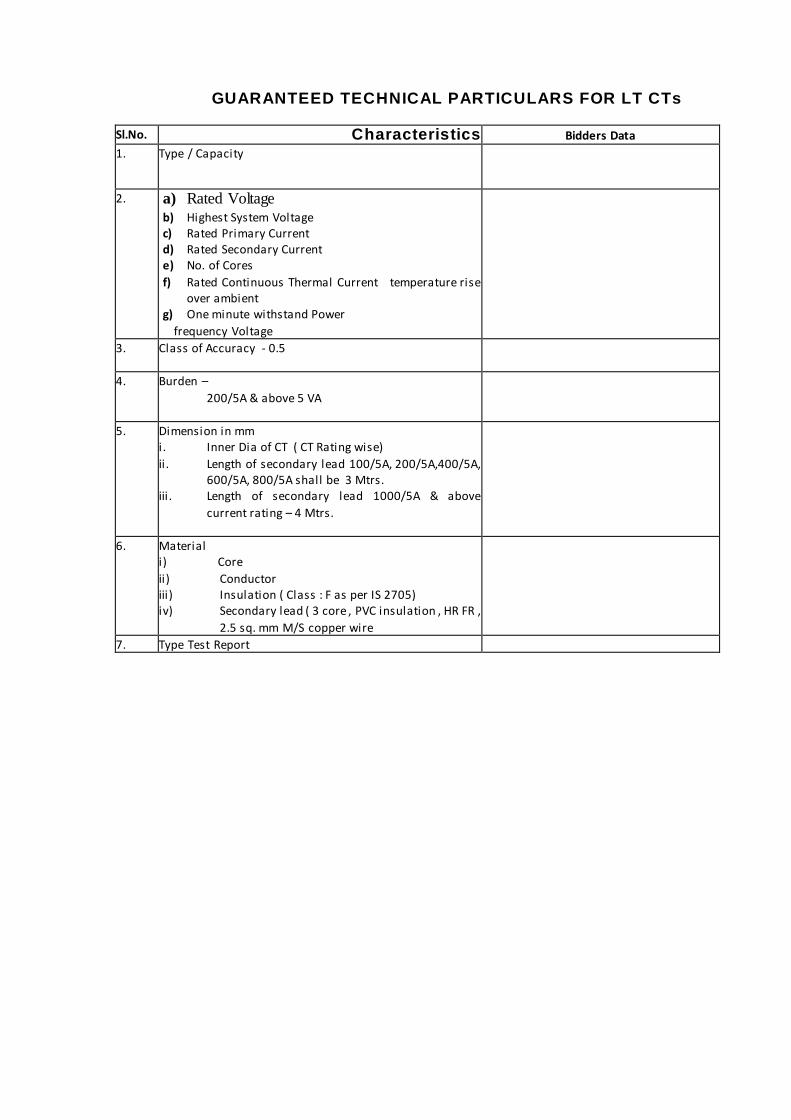
GUARANTEED TECHNICAL PARTICULARS FOR LT CTs
Sl.No. Characteristics Bidders Data
1. Type / Capacity
2. a) Rated Voltage b) Highest System Voltage c) Rated Primary Current d) Rated Secondary Current e) No. of Cores
f) Rated Continuous Thermal Current temperature rise over ambient
g) One minute withstand Power
frequency Voltage
3. Class of Accuracy - 0.5
4. Burden –
200/5A & above 5 VA
5. Dimension in mm i. Inner Dia of CT ( CT Rating wise)
ii . Length of secondary lead 100/5A, 200/5A,400/5A, 600/5A, 800/5A shall be 3 Mtrs.
iii . Length of secondary lead 1000/5A & above
current rating – 4 Mtrs.
6. Material i) Core
ii) Conductor iii) Insulation ( Class : F as per IS 2705) iv) Secondary lead ( 3 core , PVC insulation , HR FR ,
2.5 sq. mm M/S copper wire
7. Type Test Report

Technical specification of GSM/GPRS modem 1. Modem specifications:
The modem shall be suitable for communication with electronic energy meter. The modem shall be used for remote meter reading of electronic energy meters via GPRS infrastructure. Various features of intelligent GPRS modem are described as below:
(i) Power Supply Section:
a. The modem shall have three phase AC input supply and should be capable of proper functioning within the power supply range of 50 to 540V AC, 50 Hz.
b. Withstand capacity against surges should be upto 6.0 kV.
(ii) Communication Interface: a. The RS232 output shall be provided on a 9-pin female connector for connection
to electronic energy meter’s optical/ serial communication port through suitable communication cable.
b. Communication to external world using GPRS.
(iii) GSM / GPRS Section: a. The modem shall operate in Dual Band GSM 900/1800MHz. b. The modem shall be compliant with ETSI Phase 2 Standard.
o Class4 (2W) @ 900 MHz o Class 1 (1W) @1800 MHz
c. Circuit switch data transmission rate up to 14.4 Kbit/Sec. d. GPRS class B and Multi slot class 10 support e. Packet Channel Support: PBCCH f. Coding Schemes: CS1 to CS4
(iv) RF section:
a. SMA (F) interface shall be provided on the enclosure for Antenna connection. b. Gain of Antenna should be of 5 dbi.
(v) SIM Card Section:
a. For placing the SIM Card, a SIM card holder shall be provided on the modem and shall be accessible from outside without opening the modem enclosure.
b. The SIM Card supported shall be of 3V Interface. c. SIM card holder shall be provided with suitable sealing provision on the device
cover.
(vi) Network Identification Section: a. The modem shall perform auto network registration at power up. b. Three different coloured LEDs shall be provided on the modem which shall depict
the current functioning status. o Power / Network Registration / Signal strength - RED colour o Data transfer between Meter and Modem - Yellow colour o Data transfer on GSM / GPRS - Green Colour
(vii) IS/IEC Specifications:
The modem shall meet the following IS/IEC specifications:

1 Impulse voltage test IEC61000-4-5(95-03)
2 AC voltage test IS13779:1999 3 Insulation resistance test IS13779:1999
3 Electrostatic Discharge (ESD) IEC61000-4-2(1995-02)
4 Electromagnetic radiated HF susceptibility IEC61000-4-3(1995-02) 5 Fast transient Burst test IEC61000-4-4(1995-02)
6 Radio Interface Measurement (CS) IS6842 7 Surge Immunity test IEC61000-4-6
9 Dry Heat Test IS-13779:1999 10 Cold Test IS-13779:1999
11 Damp Heat Cyclic Test IS-13779:1999
12 Vibration test IS-13779:1999 13 Shock test IS-13779:1999
14 Spring Hammer test IS-13779:1999
(viii) Environmental specifications:
a. Operating temperature range : -10 degrees to +55 degree b. Humidity : 95% RH (non – condensing)
(ix) Mechanical Specifications:
a. Mounting Arrangement: A suitable wall mounting arrangement shall be provided.
b. The modem shall comply with IP54 rating. c. Sealing Arrangement: The base and top cover shall have a suitable sealing
arrangement d. The modem shall be housed in an enclosure of engineering plastic.
(x) Memory:
a. The modem shall have minimum memory of 256 KB.
(xi) Functional specifications (Communication device (Modem) proposed for DT): Modem shall be suitable for communication with electronic energy meter. The modem shall be used for remote meter reading of electronic energy meters via GSM/ GPRS infrastructure with suitable AMR Software.
Various features of intelligent GSM/ GPRS modem (to be installed with electronic energy meter) are described as below:
a. Health Check and diagnostics
i. Signal Strength measurement
Modem shall log minimum Signal Strength within an interval of 30 minute period this measurement is done on a continuous basis and logging take place at the end of 30 minute interval. Maximum 48 logs shall be available for minimum signal strength.
ii. Logs for Connection Counts The modem shall maintain logs of connection counts for:

Total connections attempted Connections failed at PPP
Connections failed at TCP Backend software should read these counts maintained in modem with date
and time stamp.
iii. Log for long communication break Modem shall log for failure in communication (with backend software) for a continuous 24 hours working duration excluding power outages. This shall also be possible to send on SMS.
iv. Log for Critical operating temperature Modem engine shall intelligently log/monitor Critical operating temperatures.
v. RF Reset The modem RF shall automatically reset in event of communication failure with backend software after exhausting all fixed retry counts in scheduled attempts.
vi. Battery status monitoring Modem shall monitor the Battery Status (Voltage level) on continuous basis.
vii. NSP (National Service Provider) related information Modem shall be able to provide following information for the diagnostic
purposes:
MNC ((Mobile Network Code) BTS registration info
IMEI (International Mobile Equipment Identity) Number IMSI (International Mobile Subscriber Identity) Number
The information above shall be made available on query from users using backend software or any mobile device through SMS.
b. Auto Registration Feature
GPRS modem shall have a special feature that whenever it shall connect to the meter and get power up, it will automatically connect to the AMR software at data centre and registered itself. Installer can validate the registration of modem at GPRS network by blinking rate of LEDs provided in modem. This feature helps utility to reduce the failure cases and occurrence of site visits due to wrong installation.
c. Outage Notification (optional with battery variant) Modem shall also send the SMS to pre-defined nos. through limited battery availability as soon as power is gone and similar message is sent on recovery of power in meter.

d. Modem reset feature
Modem shall intelligently reset the engine periodically when deregistered in the network so to ensure it could not hang up in any circumstances.
Guaranteed Technical Particulars for GSM/GPRS modem
Sr. No. Item Bidder’s Particular
1. Operating Band - Dual Band EGSM 900/1800 MHz
2. GPRS class B and Multislot class 10 support 3. Interface with electronic energy meter- RS232 D type 9F
connector
4. Dual band external antenna of 5dBi gain with SMA connector
5. Three phase power supply input (50 V to 540 Volts AC, 50 Hz)
6. Surge withstand capacity - 6 kV 7. Enclosure material- Engineering plastic
8. Sealing- The modem base and top cover shall have suitable arrangement for sealing.
9. Modem should be provided with three different coloured LED’s indicating its functioning status; LED’s should be visible externally.
10. SIM card holder– to be accessible from outside without opening the modem enclosure
11. Internal Memory– 256 KB
12. IP-54 13. SMS on power off and power on condition

Central Data Centre Hardware at MSPDCL end
Sr. No.
Item Unit Qty. Remarks
1. AMR Application Servers H/W with OS
No. 1 Processor :Intel Xeon Quadcore Memory :8GB Internal Storage: 2X146GB OS : Windows2012 or Equivalent
2. Database Servers H/W No. 1 Processor: Intel Xeon Quadcore Memory: 8GB Internal Storage: 6X146GB in RAID 0+1 OS : Windows2012 or Equivalent
3. Database license- Standard Edition
No. 1 Standard Version (Oracle/ SQL / or as per requirement
4. Software for Data collection, and conversion to CSV/XML format specified by SI
No. 1
5. Client PCs with keyboard and optical mouse & 18" TFT
No. 4 Processor: Intel Xeon Quadcore RAM: 8 GB Internal Storage : 300GB OS: Windows 8 or higher
6. GSM/GPRS Modem No. 4 For GPRS modem configuration and on-demand reading
7. UPS- 5KVA with 60 min back up Nos. 1
8. GPS clock Nos. 1
9. Printer B/W , A4 size , heavy Duty
Nos. 2
10. Antivirus & MS office for 5 years
Nos. 6 License for Servers & Client PCs as per requirement.
11. Firewall Nos. 1 As per requirement
12. Ethernet Switch - managed (16 Port)
Nos. 1
13. Rack for Servers No. 1

INSTALLATION TERMS AND CONDITIONS
1.0 INSTALLATION TERMS & CONDITIONS:-
Complete List with details of all DT metering points, where installation has to be carried out shall be furnished to successful bidder along with order.
All the available relevant data & existing database at Utility end in soft & hard copy shall be provided.
MSPDCL shall appoint a project coordinator / nodal officer for day to day activities.
Prior to commencement of work, MSPDCL shall issue necessary Identity Card to Bidder’s / contractor’s staff enabling access of Distribution Transformers during project execution period.
Necessary shut downs as & when required shall be arranged by MSPDCL as per work schedule and advance intimation also provide to effected consumers.
The required seals should be provided by the bidder, meter cover – 1 No., Meter Box one each.
The modem shall be powered from the same PT supply from where the meter is connected.
Installation of external GPRS Modem with Antenna will be carried out in meter box.
After maintenance work functional testing of the meter & modem will be carried out. During installation period MSPDCL or its concern agency shall depute their staff to read the meter through RMR from their central station on the receipt of any information from installation teams. On the completion of meter reading MSPDCL or its agency’s staff shall inform to concern team for successful reading.
If any civil work required at any site during installation or maintenance that including proper earthing, shall be carried out by the MSPDCL.
Supervisor with adequate academic qualification and experience shall be made available by bidder for a group of teams for on-site technical assistance and conflict resolution.
Contractor should submit Signals related issue with SIM card on weekly basis to further inform to service provider for necessary action on priority basis.
Contractor should submit a work completion report considering the details of material consumed in line with DT identification.
Items not covered under the scope of work to be arranged by Discom.

2.0 Inputs from utility:
The following shall be facilitated by util ity for carrying out the above requirements:
Permission to the agency to visit DTM locations for survey and subsequent inspection/ installation of metering systems as required
Local assistance for gathering details of meter details etc. Local shutdown for installation of metering systems and modems etc. as
required.
A concerned circle officer will be assigned by utility for following requirements:
a. At the time of field visit, availability of manpower at site
Monthly feedback of meters installed & commissioned at utility end, with date of commissioning.
Details of all DTM locations together with details of which Circle/ Division it belongs to.
Changes in network configuration/ short duration changes (with date/time) from substations for the reporting month will be provided on a weekly/ monthly basis.
Changes of DTs switched from one feeder to the other (with date/time) as logged in control rooms for the reporting month will be provided on a weekly/ monthly basis.
Details of new DTs connected to feeders with date of connection & date of metering the DT
DTs permanently disconnected from any feeder with date of disconnection.
DTs upgraded in any feeder with date (when a DT is replaced by another DT of higher/ lower capacity).
Soft copy of consumer database with their connectivity to each DT with DT name/code, address, K No., category, sanctioned demand, meter details (make, serial no, no. of digits & MF), and last 2 meter readings with meter reading dates. Master Data/ HT and LT consumer billing transaction data will be required as per attached format below.
Complete single line diagram of the LT network from DT with details of Consumers connected to each pole.
Utility will have a SLA agreement with NSP (Network service provider) for all desired GPRS related parameters (Signal strength, GPRS channel allocation, GPRS data rate etc.) for making successful AMR.
Any rework due to change in NSP/ SIM replacement shall be taken care by utility.